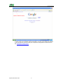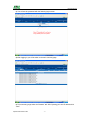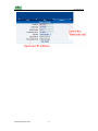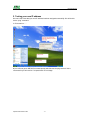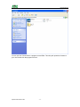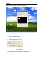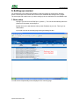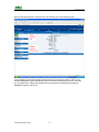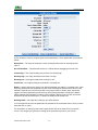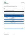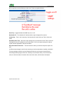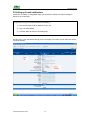
1
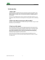
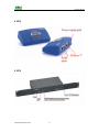
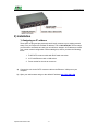
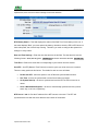
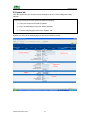
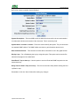
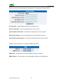
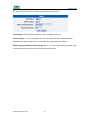
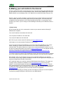
EP2 EP8 User Manual Copyright © 2007,ATAL EP2 EP8 Manual 1) Introduction 1. What is EP? 2. What’s the difference between the EP2 and the EP8? 3. How to use this manual 4. EP2 5. EP8 2) Installation 1. Assigning an IP address 2. Testing your new IP address 3. Upgrading the firmware 3) Setting up a sensor 1. Basic Setup 4) Notifications 1. Setting up a trap 2. Setting up Email notifications 5) System Settings 1. Network Settings 2. System tab 6) Making your unit visible to the internet Updated until firmware 382L -2- EP2 EP8 Manual 1) Introduction 1. What is EP? The EP2 and EP8 are intelligent devices for monitoring environmental variables, power, physical threats and security. The units come with an embedded, proprietary, Linux like operating system. Included in this is a TCP/IP stack, Web server, full SNMP support, Email and SMS. Any of our ATAL intelligent sensors can be connected via the RJ45 connections, or you can add dry contact connection for monitoring UPS, security systems and air conditioning status. 2. What’s the difference between the EP2 and EP8? The EP2 is a small unit with facility for 2 RJ45 sensor inputs. The EP8 is a larger unit with the facility for up to 8 RJ45 inputs. 3. How to use this manual This manual aims to provide the user with a step by step guide on how to get your unit set up and functioning. It will introduce the primary features of the unit by way of tutorials. You can either go through the whole procedure from start to finish, or, if you wish, use each tutorial as a standalone lesson. The start of each lesson gives an “entry point profile” which details how to get to the start point of the lesson and assumes previous knowledge through completion of previous tutorials. At the end you find a FAQ that covers common questions and problems you may encounter. If however you need any further assistance please don’t hesitate to contact our support team. Updated until firmware 382L -3- EP2 EP8 Manual 4. EP2 5. EP8 Updated until firmware 382L -4- EP2 EP8 Manual 2) Installation 1. Assigning an IP address These units are plug and play devices that will easily connect to your existing network setup. Every unit ships with a default IP address. This is 192.168.0.100. The first steps you will need to undertake to install your unit will be to assign it an IP address to match your current network configuration. Before starting this, ensure you have the following items:1. RJ45 CAT5 crossover cable with RJ45 male connection 2. A PC with Ethernet card or LAN socket. 3. Power socket for the unit to connect to a) Connect the unit via the CAT5 crossover cable to the Ethernet / LAN port on your computer. b) Open your web browser and go to the default IP address http://192.168.0.100 Updated until firmware 382L -5- EP2 EP8 Manual In some cases your computer might not be able to connect to this default IP address. In this situation you need to set up your computers routing table to allow access to this. See here for this process. Updated until firmware 382L -6- EP2 EP8 Manual c) You will now be presented with the following login screen. d) After logging in you will be taken to the main summary page. e) From summary page select the “Network” tab. After inputting your new IP address click “save” Updated until firmware 382L -7- EP2 EP8 Manual Updated until firmware 382L -8- EP2 EP8 Manual 2. Testing your new IP address We now need to test that your new IP address has been assigned successfully. We will do this via the “ping” command. 1. Click start/run…… 2) You will now get an MS DOS command prompt which shows the ping results. If this is unsuccessful you will receive a “request timed out” message. Updated until firmware 382L -9- EP2 EP8 Manual 3. Upgrading the firmware As we are constantly releasing new firmware with added capabilities it is recommended you upgrade to the latest firmware. Please contact us for the latest firmware update file 1) When you download your firmware it will come in a zip package. Extract this to your desktop into a folder named firmware. When you open this folder you will see something like the following:- Updated until firmware 382L - 10 - EP2 EP8 Manual You can see one of these files is a program named IPSet. This utility will upload the firmware to your unit. Double click the program to boot it. Updated until firmware 382L - 11 - EP2 EP8 Manual 2) When IPSet loads you will be met with a screen similar to this:- 1) Select firmware upgrade 2) Type in the IP address of your unit 3) Type in your administrator password 4) Click browse, a new window will pop up 5) Select the zipped firmware file, click open. 6) When complete the message “upgrade complete” will be displayed Updated until firmware 382L - 12 - EP2 EP8 Manual 3) Setting up a sensor For the purposes of this manual and tutorials we will cover setting up a dual temp / humidity sensor. The first part of the tutorial will cover the basic installation and settings for the sensor. The second part will explain how to go about setting up various notifications such as SNMP traps. 1. Basic setup a) Plug in your sensor to the RJ45 port 1 (sensor 1). The unit will automatically detect the presence of the sensor and configure it. b) Now return to the web browser and input the IP address of your unit. Then log in as administrator. c) You will now see the summary page looking something like this:- You will see the temp/humidity sensor displayed in the summary page. Updated until firmware 382L - 13 - EP2 EP8 Manual d) From this page select the “Sensors” tab. This will bring you to the following page:- In this example we have selected the humidity sensor from the sensor menu on the left. The sensors highlighted in green indicate that they are currently connected to the unit. In this case you can see there is a temp and humidity sensor connected (dual sensor) and so they are highlighted in green in the menu. Updated until firmware 382L - 14 - EP2 EP8 Manual e) This window is used for configuring the sensors parameters. These parameters are explained below :Description :- The name of the sensor. Use a meaningful name such as “humidity sensor office1” Go Online/Offline :- This takes the sensor on or offline without unplugging it from the unit Critical high :- The %age humidity level at which it is critically high Warning high :- the %age humidity level at which it is high Warning low :- the %age humidity level at which it is low Critical low :- the %age humidity level at which it is critically low Rearm :- Used to prevent the sensor from flickering between two states. For example if the “High Warning” threshold for the temperature sensor is set to 80 degrees and the sensor were to vary between 79 and 80 you could be faced with a very large number of emails, traps, and events logged. The Rearm parameter prevents this by forcing the temperature to drop by the Rearm before changing the state back to normal. In this example if Rearm is set to 2 then, the sensor would have to drop from 80 down to 77 before the status would change from Reading offset :- will adjust the reading by your offset amount. In our example we have set the parameters as indicated in the screenshot above. Once you have done this click on “save”. For information on setting up other sensor types please refer to the manual for your specific sensor. This will give you guidance in setting up the parameters specific to your sensor. Updated until firmware 382L - 15 - EP2 EP8 Manual 4) Notifications 1. Setting up a trap The EP2 and EP8 can send an SNMP trap message to two different hosts. Whenever the status changes for a sensor that is online, a trap message can be sent. To get to the entry point of this tutorial, complete the following:1) log into the web interface as administrator 2) from summary page select the Traps tab a) After going to the “traps” tab you can see the two traps (“Trap 1”, “Trap 2”) Updated until firmware 382L - 16 - EP2 EP8 Manual b) The traps have various fields you need to set. These are explained below. Send Trap :- toggles whether the SNMP trap is on or off Destination IP :- The destination IP address that the trap message will be sent too. Community :- This is the Community of the host that will receive this trap. This is often set to public Send Keep Alive Trap :- Will send a trap message at your preset time interval. This is useful for informing the user as to whether the unit is still online, or for if you require collection of data at regular intervals regardless of the sensors status. Keep Alive Resend Intervals :- The time interval in which you want the keep alive traps to be sent. A different trap message is sent for each sensor type such as temperature, humidity, and switch. The trap messages include 6 var bind fields that include the current sensor status (Normal, Critical High, Warning High, Critical Low, Warning Low, and sensor Error), the current sensor value, the level exceeded, the sensor index, the sensor name, and the sensor description. Updated until firmware 382L - 17 - EP2 EP8 Manual 2) Setting up E-mail notifications As well as, or instead of, using SNMP traps you can also be notified of a sensors change in status by an e-mail report. To get to the entry point of this tutorial do the following :1) point your browser to the IP address of your unit 2) Log in as administrator 3) Click the “Mail” tab from the summary page. a) Click on the “mail” tab and this brings you to a new page. From here you can setup the various e-mail parameters. Updated until firmware 382L - 18 - EP2 EP8 Manual b) You can now set up the individual Email options from the fields shown below. Send Mail :- This toggles whether the send Email option is on or off. SMTP Server :- The address of your SMTP server SMTP Authentication :- check this option if your SMTP server requires authentication SMTP Server Login Name :- The user name to login to your SMTP server SMTP Server Password :- The password used to login to your SMPT server E-mail subject :- The subject you wish to have for the e-mail. Eg. “EP notification” Timeout :- You can increase the timeout for SMTP servers that have poor connectivity. It is best to leave this number as low as possible while still allowing for communication with the SMTP server to continue. Resend Intervals :- The time between which the e-mails will be sent Maximum Times To Resend :- Set the number of times you wish for the notification e-mails to be resent. Send Keep Alive Email :- This option will tell the unit to send a heartbeat e-mail. This is useful to tell if the unit is still online or not. It is also used when you require collection of data at regular intervals. Keep Alive Email Resend Interval :- The amount of time between which the keep alive emails are sent. After setting your parameters click the save button. Updated until firmware 382L - 19 - EP2 EP8 Manual c) Below this you will see there is anther section. This is for configuring who the e-mails are to be sent too. Mail From :- The email address which you would like the e-mail to appear from. Due to anti-spam features of some SMTP servers this address must be authorized on the SMTP server otherwise the server may deny the email. Mail Recipient :- The email address of the person you wish for the email to be sent to. Mail Cc1-5 :- Up to five additional e-mail addresses may be added. When you have filled in your required fields remember to click “Save”. d) At the bottom of the page you have two further options. Status of most recent Mail :- This can be either “No Status” “Success” or “Failure” Last Error Message :- This is a debugging aid. If the email is not successfully sent, you may find the reason for the problem here. Test Email :- Useful when you first set up the SMTP settings to ensure they are working, or anytime thereafter. Before a test mail can be generated ensure the previous fields described have been completed. Updated until firmware 382L - 20 - EP2 EP8 Manual 5) System settings 1) Network settings The networks settings page allows you to change network settings for your unit such as the IP address etc. To get to the entry point of this tutorial complete the following :1) Point your web browser to the IP address of your unit 2) Log in as administrator 3) From the settings page, select the network tab. a) After clicking the “Network” tab you will be taken to this page :- Updated until firmware 382L - 21 - EP2 EP8 Manual b) Once on this page you can setup the network settings as indicated below :- IP Address :- Use this to change the IP address of your unit Subnet Mask :- Use this to assign the subnet mask of your unit Default Gateway :- Assign the default gateway of your device Domain Name Server :- IP address of your DNS. Used if you wish to use a DNS address for your unit instead of accessing via the IP address. Use DHCP :- The unit can use DHCP to assign its IP address, or it can use a statically assigned IP address. To use DHCP choose “Use DHCP” from the list box and press set. To stop using DHCP choose “Do Not Use DHCP” from the list box and press set. Statically assigning an IP address also turns off DHCP. You can force the EP2 and EP8 to voluntarily give up its IP lease and request a new IP lease by choosing Use DHCP from the list box and pressing “set”. Ethernet MAC ID :- This is the MAC address of your unit. This is a read only field Ethernet Duplex Mode :- The duplex mode and speed of your unit. This is a read only field also. Ensure you apply your new settings by clicking on the “save” button. Updated until firmware 382L - 22 - EP2 EP8 Manual c) Below this, there are some further settings for the time and date. RTC Battery Status :- This field displays the status of the Real Time Clock battery on the unit. If the status displays “Bad”, you must replace the battery; otherwise, when the EP2 or EP8 does not have main power, the clock will stop running. Therefore, you must re-configure the system time settings on every reboot. Date and Time Settings :- Enter the new date and time in this field. The date and time use the following format : date/month/year (dd/mm/yy) and hour:minute:second (hh:mm:ss) Time Zone :- Select time zone that is corresponding to your location from this list box. Use NTP :- An NTP (Network Time Protocol) is used to synch your units clock over a network. There are many options in this list box. The details for each one are as follows: Do Not Use NTP - select this option to turn off the time synchronization feature. One Time - the time is synchronized once the Save button is pressed. On System Start Up - the time is synchronized once the EP2 or EP8 is turned on or reboot. Once a Month/Week/Day/Hour - the time is automatically synchronized every month, week, day, or an hour, respectively. NTP Server 1 and 2 :- Set the IP address of the NTP servers to be used. The NTP will synchronize the time with the server that has less number of the stratum. Updated until firmware 382L - 23 - EP2 EP8 Manual 2) System tab From the systems tab you can input various settings for the unit. These settings are mostly optional. To get to the entry point of this tutorial complete the following :1) Point your browser to the units IP address 2) Log in as administrator using your admin password 3) From the summary page click on the “System” tab a) When you arrive at the settings page you will see the following screen :- Updated until firmware 382L - 24 - EP2 EP8 Manual b) The first section is entitled “System Settings” System Description :- This is an MIB II value set when the microcode for the unit was installed. It includes the build time and version of the microcode. This is a read only field. System Name / Location / Contact :- These are used to identify the system. They are accessed via standard SNMP utilities. The SNMP utilities use these to get information about the unit. Data Collection Period :- This controls how often data is collected for use in the graph function. Display Logo : Turn off displaying the logo by using this option. This option can be turned off to allow the web pages to be loaded faster. Send Email / Trap on boot up :- Use this option to send an Email and SNMP trap each time the system boots up. Delay Time for Email / Trap on boot up :- The time in seconds to delay before sending the boot up Email or trap. Remember to click the “Save” button after making any changes. Updated until firmware 382L - 25 - EP2 EP8 Manual c) The next section is used for setting a user password, or changing the admin password. Use Password :- toggle whether the password is required or not New User Password :- Type in the password for the user account Confirm New User Password :- Confirm the new password for the user account New Admin Password :- Type in the password you wish for the admin account Confirm New Admin Password :- Confirm the new password for the admin account d) Next you have the options for resetting the SNMP trap settings SNMP Port :- Use this option to reset the SNMP port setting to its default SNMP Trap Port :- Use this option to reset the SNMP Trap Port to its default setting Updated until firmware 382L - 26 - EP2 EP8 Manual e) Finally you have the option for setting up the system log parameters. Clear Syslog :- Used to clear the system log of the messages for the unit Remote Syslog :- You can set up the unit to send its syslog message in a standard format acceptable to a remote syslog server. For example, the Logalot system from Somix. Remote Syslog IP Address, Remote Syslog Port :- You can set the IP address and port of the remote syslog server to which the unit will send the log messages. Updated until firmware 382L - 27 - EP2 EP8 Manual 6) Making your unit visible to the internet So far the manual has simply covered the basic set up. The setup we have just created will allow you to access your unit on a Local Area Network (LAN). We have setup SNMP traps so that your SNMP software, such as Whatsup Gold, or HP Openview can collate information from your unit. However, what if you wish to be able to remotely access your unit from anywhere in the world? This is possible; however, the following steps are only an outline guide. Your exact setup and configuration will often depend on your network equipment and setup. You are going to need access to your router, if you are using one and knowledge of whether your IP address is static or dynamic. 1) Simple setup a) Lets imagine that your unit is connected to a router on your network, and the following IP addresses are assigned. Your units IP address is the default 192.168.0.100. Your computers IP address is 192.168.0.200 Your routers IP address is 192.168.0.300 b) To find out your routers external IP address go to www.whatsmyip.com Lets imagine your routers external IP address is 278.67.04.09 c) You now need to setup port forwarding on your router. This varies depdning on your routers model. Generaly you need to point your browser to your routers IP address (in this case 192.168.0.300). This will then allow you to log into your routers administration interface. You can find how to go about doing this for your router on www.portforward.com For an example of how to do this for a commonly used router follow this link :http://www.portforward.com/english/routers/port_forwarding/Linksys/WRT54G/HTTP.htm You need to setup your routers HTTP forwarding to port 80. This will then mean when you access your router using the external IP address you will be forwarded to your units internal IP address. d) To test this, open your web browser, and go to your external IP address (in our example 278.67.04.09). If your using a dynamic IP address, its best to check it again before doing this as it may have changed since the start of this tutorial. e) To make this easier you could use a dynamic DNS (Dynamic Name Server). This means you no longer need to remember IP address’s or use www.whatsmyip.com to find out your IP address. You will instead register a domain name (for example my EP2.homeip.com). This will then automatically point your routers external IP address (e.g. 278.67.04.09). This will require you to register the domain name and open an account with a DNS server provider. We recommend www.dyndns.com as they allow up to 5 free domain names to be registered. f) If you have set everything up correctly you will now be able to access your unit from anywhere in the world by simply pointing your web browser to your DNS address. Updated until firmware 382L - 28 - EP2 EP8 Manual 7) Setting up your PC’s routing table *To set up the routing table, open a DOS window (start, run type command press enter) and at the command prompt enter. >route add 192.168.0.100 10.1.1.20 Where 10.1.1.20 is the IP address of the Ethernet interface on the PC that the unit is plugged into with the crossover cable. Now ping* 192.168.0.100 to see if the connection was successful. Updated until firmware 382L - 29 -