1
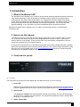
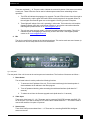
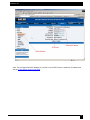
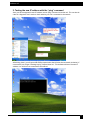
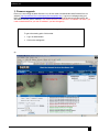
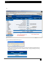
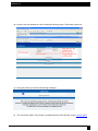
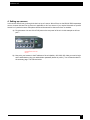
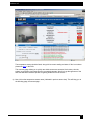
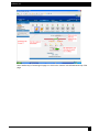
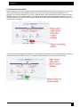
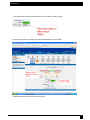
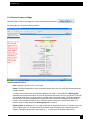
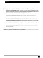
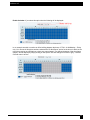
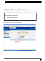
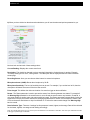
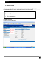
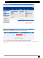
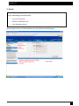
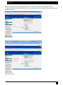
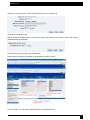
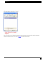
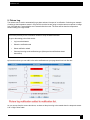
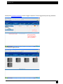
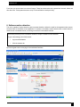
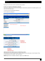
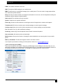
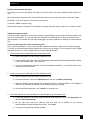
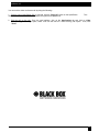
November 2007
EME124A – EME128A
EME129A-20, EME129A-60
ServSensor V4P
User Manual
ServSensor V4P
ServSensor V4P.................................................................................................................................................... 1
1) Introduction ....................................................................................................................................................... 4
1.
What is ServSensor V4P? .......................................................................................................................... 4
2.
How to use this manual .............................................................................................................................. 4
3.
Front and rear panels ................................................................................................................................. 4
1.
Reset button. ........................................................................................................................................... 5
2.
Video input. ............................................................................................................................................. 5
3.
Sensor ports............................................................................................................................................ 5
4.
USB port ................................................................................................................................................. 6
5.
Mic Out.................................................................................................................................................... 6
6.
Audio in / out ........................................................................................................................................... 6
7.
Serial port (RS232).................................................................................................................................. 6
8.
Ethernet port ........................................................................................................................................... 6
9.
RS485 port .............................................................................................................................................. 6
10.
Power connector................................................................................................................................... 6
11.
External ground .................................................................................................................................... 6
2) Installation......................................................................................................................................................... 7
1. Setting up the IP address ............................................................................................................................. 7
2. Testing the new IP address with the “ping” command................................................................................. 11
3. Firmware upgrade...................................................................................................................................... 12
4. Setting up a sensor .................................................................................................................................... 15
1. Using internal Mic as a sound detection sensor .......................................................................................... 23
3) Notifications .................................................................................................................................................... 25
1. Adding a notification................................................................................................................................... 25
2. SNMP trap ................................................................................................................................................. 27
3. E-mail ........................................................................................................................................................ 31
4. SMS notification......................................................................................................................................... 35
4) Camera ........................................................................................................................................................... 40
2
ServSensor V4P
1. Basic setup ................................................................................................................................................ 40
2. Pan / tilt functions of the camera. ............................................................................................................... 42
3. Automating camera movements................................................................................................................. 44
4. Recording from the camera........................................................................................................................ 47
5. Picture Log ................................................................................................................................................ 51
6. Software motion detection.......................................................................................................................... 53
5) Mapping .......................................................................................................................................................... 56
1. Adding a map............................................................................................................................................. 56
2. Monitoring via the map interface................................................................................................................. 61
6) Making my unit visible on the internet .............................................................................................................. 63
FAQ .................................................................................................................................................................... 64
a) I can not see the temperature sensor displayed on summary page............................................................. 65
b) I can not access my units web interface ..................................................................................................... 65
c) What do my LED lights mean? ................................................................................................................... 66
d) I have forgotten my units IP address .......................................................................................................... 68
e) I have forgotten the password for my unit. .................................................................................................. 69
f) Can I use DHCP to assign my units IP address? ......................................................................................... 69
g) How do I set up my routing table? .............................................................................................................. 69
h) How can I change my administrator password?.......................................................................................... 70
i) What function do the different types of notifications provide?....................................................................... 70
j) Can I connect my unit via WiFi? .................................................................................................................. 71
k) What is the Heartbeat message? ............................................................................................................... 72
l) What is the network sniffer .......................................................................................................................... 72
j) Can I use the camera for a video conferencing call?.................................................................................... 72
3
ServSensor V4P
1) Introduction
1. What is ServSensor V4P?
The ServSensor V4P integrates over 10 years of environmental monitoring experience with the latest solid
state camera technology to push the boundaries of disaster protection. Now you can sense and see
problems before they lead to business disruptions. It is a high speed, accurate, intelligent monitoring
device, featuring a completely embedded host and Linux Operating System. The design is based on our
successful sensorProbe8L and cameraProbe8, but with improved hardware. This unit includes video
digitizing capability, so you can connect your own cameras through the rear panel connectors.
Black Box has prided itself on bringing a low cost, easy to use monitoring solution to market with the
ServSensor V4P.
2. How to use this manual
This manual is meant to provide the user with a step by step guide on how to configure and set up their
unit. It utilizes screen shots in an effort to make things simpler for the user to follow. It is split up into
sections that form “mini tutorials”. These cover the basic set up and common configurations of the unit,
and give an introduction to its most useful features.
At the end of the manual there is a FAQ section that provides some further in-depth information regarding
specific set ups and answers some commonly asked questions. If you need any further information or help
with using your unit then please contact us on [email protected] and one of our technical support
staff will be only too pleased to help you with any information you require.
3. Front and rear panels
Fig 1. Front panel
The front panel has several LEDs which display the units status and notify you as to its activity.
1. Power LED
When the unit is powered up the power LED will be lit continuously. If the power LED is flashing then it
indicates a problem with the CPU. If you notice this then please contact us on [email protected]
2. Ethernet LED
The activity and Link100 LEDs indicate network connectivity and activity. The Link100 LED will light
up when there is a network connection present. The activity LED will flash when there is network traffic
being sent or received by the unit.
3. Status / Online LEDs
4
ServSensor V4P
These are numbered 1 – 8. They are used to indicate the connectivity status of the sensors connected
to each port. These LEDs also can be used to indicate system status when undertaking various
operations.
1. The LEDs will indicate the progress of an upgrade. The red LEDs will move from left to right to
indicate activity, and the green LEDs will indicate overall progress of the upgrade. When all
the red lights are off and all green are on the upgrade / recovery process is complete.
2. These lights will indicate if the unit is operating in safe mode. This is when the unit loads the
Operating System (OS) with a minimal set of drivers. If your device enters safe mode after
rebooting then please contact us on [email protected]
3. The unit may enter recovery mode if a firmware upgrade has been incomplete. This will be
indicated by the unit displaying a continuously lit row of red LEDs. If this happens please
contact us on [email protected]
4. Mic
The mic is a small hole for access to the internal microphone. This can be used as a sound sensor (or
an external mic can be used) See here for more information
Fig 2. Rear panel.
The rear panel of the unit is home to the various ports and connections. The functions of these are as follows :1. Reset button.
The red reset button is used to perform the following functions
1. To announce the IP address of the unit. This is announced through the internal speaker. It
also broadcasts the IP address to the IPset program.
2. Turns off password checking when accessing the web based interface (hold down for 7
seconds)
3. To reboot the unit into the firmware upgrade mode (hold down for 12 seconds)
2. Video input.
There are 4 video inputs (V1 - V4). These are used to connect a PAL/NTSC camera using BNC 750
hm 30 Au jack. If you wish to connect a PTZ camera the 4 RS485 labeled PT1 – PT4 can be used to
connect the cameras via a pelco –D protocol.
3. Sensor ports
There are 8 RJ45 ports numbered from 1 – 8. These are for connecting BLACK BOX intelligent
sensors to the unit.
5
ServSensor V4P
4. USB port
The unit is equipped with a single USB 1.1 port. This can be used, for example, to connect a USB
GPRS/GSM compatible modem, a USB WiFi dongle or USB Bluetooth dongle.
5. Mic Out
This is used to connect an external microphone for voice modem applications.
6. Audio in / out
The in is used to connect an external microphone, the output for external speakers.
7. Serial port (RS232)
Used to attach a serial voice modem, or mobile phone.
8. Ethernet port
This RJ45 port is used to connect your unit to the network.
9. RS485 port
Used for Modbus slave support.
10. Power connector
This is a 7.5V DC plug. We recommend you using a 7.0 – 9 V, 2.5 A power supply.
11. External ground
The EXT. GND can be used to external ground the unit.
6
ServSensor V4P
2) Installation
1. Setting up the IP address
Every unit is shipped with the default IP address of 192.168.0.100 First we will go through the process of
changing this IP address to fit your own network configuration.
Ensure the following items are available to you before starting:1. RJ45 CAT5 crossover cable with RJ45 male connection
2. A PC with Ethernet card or LAN socket.
3. Power socket for the unit to connect to
a) Connect the unit via the Ethernet port of the unit to your computers LAN or Ethernet port with a CAT5
crossover cable.
b) Open a web browser and type the default IP address, hit enter.
In some cases your computer might not be able to connect to this default IP address. In this situation
you need to set up your computers routing table to allow access to this. See here for this process.
7
ServSensor V4P
c) You will now be presented with the following screen. The default password for Admin is “public”. To
make your unit secure and change the password, see here.
d) Next the home page will be displayed. It will look similar to this.
8
ServSensor V4P
e) Click on “Ethernet network” from the list on the left frame of the page.
9
ServSensor V4P
Note. The unit ships with DHCP disabled. If you wish to use a DHCP server to obtain the IP address then
see the “Using DHCP” section of the FAQ.
10
ServSensor V4P
2. Testing the new IP address with the “ping” command
Once you have assigned the new IP address use the “ping” command to test the unit. This can also be
used as a diagnostic tool in order to check whether your unit is connected to the network.
After hitting “enter” you will get an MS DOS prompt window that will show the test results (as below). If
unsuccessful you will get a message saying “request timed out”. This indicates either an incorrect IP
address or a unit that is not connected to the network.
11
ServSensor V4P
3. Firmware upgrade
Ensure you are running the latest firmware. You will also need to download the latest firmware from our
website ( http://www.Black Box.com/company/firmwareupdate.htm ). Log into our webpage using your
MAC address, this is found on a sticker on the base of the unit. After the download navigate back to the
web based interface (units IP address. This manual will refer to the DEFAULT IP address, 192.168.0.1 you
need to substitute this for your own IP address if you have changed it)
This tutorial provides you the information needed to upgrade the firmware.
To get to the starting point of this tutorial:
Log in as administrator
Click on the settings tab
a)
12
ServSensor V4P
b)
c) You will then be presented with this pop up :-
Click OK. The unit will then reboot in safe mode. You will then be redirected to the safe mode web
based interface. This can take some time, so please be patient. The page will display the following
message while rebooting
13
ServSensor V4P
d) Once the unit has rebooted you will be viewing the following page. Follow these instructions.
e) during the process you will see the following messages :-
f)
The unit will then reboot. The process is complete when the LED’s are back to their “normal” status.
14
ServSensor V4P
4. Setting up a sensor
In this section we will now go through the basic set up of a sensor. We will focus on the BLACK BOX temperature
sensor; however this basic set up process is applicable to all of our sensors. If you require information on specific
functions of a particular sensor then please download the manual for that sensor from our website.
a) Plug the sensor into one of the RJ45 ports on the rear panel of the unit. In this example we will use
port 1.
b) Now point your browser to the IP address of the unit (default, 192.168.0.100). Next you need to login
as the administrator using your administrator password (default is “public”). You will then be taken to
the summary page. This is shown below.
15
ServSensor V4P
The temperature sensor should be listed, along with its current reading and status. If this is not shown
please see here in the FAQ.
This summary page allows you to quickly see which sensors are connected, their status, view the
system log, and also view footage from any connected cameras. We will now go through some of the
tools the web based interface provides for getting feedback from the sensors.
c) Now click on the temperature sensors name (indicated in previous screen shot). This will bring you to
the following page, the sensors page:-
16
ServSensor V4P
Note: another way of accessing this page is to click on the “sensors” tab indicated at the top of the
page.
17
ServSensor V4P
i) Notification thresholds
From this page you can carry out various operations as indicated above. Also view the current status (normal, low
critical, high critical etc). In the screen shot above you can see the sensor is indicating a temperature of 79
degrees F, and a status of Normal. If you click on the blue marker arrow indicated above by the “Set the required
threshold” label you can drag this marker to re-configure the thresholds. After dragging the marker click “save” In
the next screen shot you can see that this marker has been moved to make a new threshold, and along with it the
sensor status has changed.
If the marker is then dragged back to above the current reading temperature you should see the status returns to a
normal condition again. Note: If this does not happen straight away press your browsers refresh button.
18
ServSensor V4P
If you wish to take a sensor offline then click on the “sensor currently” button.
Now your page will look something like below after taking the sensor offline.
Repeat this process to put the sensor back online.
19
ServSensor V4P
ii) Advanced sensor settings
Near the bottom of the sensors page you will see the advanced mode button
By clicking this you will get the following options :-
Advanced mode functions
Units: changes units from C to F or vice versa
Rearm: The Rearm parameter is useful for sensors whose values can vary such as the temperature and
humidity sensors.
It is used to prevent the sensor from flickering between two states. For example if the Warning High
threshold for the temperature sensor is set to 80 degrees and the sensor were to vary between 79 and 80
you could be faced with a very large number of emails, traps, and events logged. The Rearm parameter
prevents this by forcing the temperature to drop by the Rearm value before changing the state back to
normal. In this example, if Rearm is set to 2 then the sensor would have to drop from 80 down to 77
before the status would change from Warning High back to normal.
Reading offset: A calibration tool. If you wish to calibrate the temperature sensor, for example, you could
enter an offset value of 5. This would mean if the sensor reads 20 degrees then it would record as 25
degrees. This figure can also be a minus figure (e.g. -5 would show 15 degrees instead of 20)
20
ServSensor V4P
The following advanced functions are for setting the time frame in which the system should delay a notification
being triggered when a sensor gives a reading that exceeds the thresholds (high warning, normal, etc).
Continuous Time to Report High Critical: This helps to eliminate unnecessary messages during minor
fluctuations. You can set the amount of time to delay a notification of a status change from high warning to
high critical. Enter the time in seconds and press the “Save” button. The amount of time that can be
entered is between 0 and 65535 seconds which equals approximately 18 hours
Continuous Time to Report High Warning: As above but delays notification for “High Warning”
Continuous Time to Report for Normal: As above but delays notification for return to “Normal” state
Continuous Time to Report for Low Warning: As above, but delays notification for “Low Warning” state.
Continuous Time to Report for Low Critical: As above but delays notification for “Low Critical” state.
Continuous Time to Report for Sensor Error: As above, but delays notification being sent for sensor
going into an error state.
Example: An airflow sensor or water detector may have temporary drops in readings which are normal operating
characteristics; a logical time limit is set to show abnormal conditions.
21
ServSensor V4P
Enable Calendar: If you select this option then the following will be displayed:-
In our example we wish to monitor an office building between the hours of 7 PM – 9 AM Monday – Friday
only. You can see in this picture we have selected the “Do Not Report” option for the hours in which we do
not wish to receive any notifications or have any events logged. You change the status of that time frame
(Report / Do Not Report) by simply clicking on the square. This will change it from blue to grey, a second
click will return it to blue.
22
ServSensor V4P
1. Using internal Mic as a sound detection sensor
The internal microphone (or an external plugged into the line in jack) can be used as a sound detector.
This tutorial provides you the information needed to setup the internal Mic as a sound detection
sensor.
To get to the starting point of this tutorial:
Log into the web based interface
Click on the sensors tab
a) First navigate to the correct page in the web interface.
23
ServSensor V4P
b) When you have clicked on the advanced mode button you will see the advanced options presented to you.
Now lets look at what each of these settings does:Current Reading: Displays the current sound level.
Description: This should be changed to give a meaningful description of what the port is sensing. Example,
"Currently sensing server room", "Wiring closet". This description will be displayed under the motion detection
sensor page.
Recording Source: Here you can choose either internal or external microphone.
Microphone boost (+20dB): Boosts the microphone by 20 dB
Microphone Sensitivity: The level of sensitivity that can be set. For example, if you set the level to 80, then the
microphone will detect more sound if the level was set a 20.
Pulse Length: This defines the minimum duration of a sound to trigger an alert notification.
Rearm: The Rearm parameter is used to prevent the sensor from flickering between two states. For example if
the Warning High threshold for the sound sensor is set to 80 and the sensor was to vary between 79 and 80, a
very large number of emails, traps, and events would be logged. The Rearm parameter prevents this by forcing the
signal level to drop by the Rearm value before changing the state back to normal. In this example, if Rearm is set
to 2 then the sensor would have to drop from 80 down to 77 before the status would change from Warning High
back to normal.
Data Collection Type: There are 3 settings for this parameter: lowest, highest, and average. Data will be collected
for the lowest, highest, or average sound reading accordingly.
Note: As for all the other sensors you can now set up the sound detector to be attached to a notification. Then when your thresholds are broken
it will trigger a specified type of notification.
24
ServSensor V4P
3) Notifications
If you setup a notification you can define the action to take when the sensor gives a reading beyond your
previously set thresholds. This allows you to determine how you will be notified that a sensors reading has reached
the specified parameters (high warning, critical etc) that we looked at in the previous section.
This tutorial provides you the information needed to setup a notification.
To get to the starting point of this tutorial:
Login as administrator
Click the “Notifications” tab
1. Adding a notification
a) First click on the “notification wizard”
25
ServSensor V4P
b) You will now have the notification wizard page displayed, like below.
We will now go through setting up a few different ways of notification step by step. To learn what the other
types of notifications do, see here.
26
ServSensor V4P
2. SNMP trap
First we will set up a notification via SNMP trap, so that when your sensor reaches a certain threshold it will send a
notification to your SNMP server.
This tutorial provides you the information needed to setup an SNMP trap.
To get to the starting point of this tutorial:
Log in as administrator
Click the “Notifications” tab
Choose “Notifications wizard”
Choose SNMP trap
a) After selecting to add an SNMP trap you will need to fill in the following information
b) Once this information is correct you can press the “Add Trap Destination” button. After clicking this you have the
option of inputting another trap, or clicking on “Next”. Now you can enter the following parameters:-
These parameters set the maximum number of times to send the trap notification and the time interval between
each notification.
27
ServSensor V4P
c) After clicking next you will be presented with the following screen:-
On this screen you can select the parameters for when to send the SNMP trap notification. In our example we
have selected to bind the SNMP trap to the temperature sensor we have connected on port 1. The trap will be sent
when the sensor reads a “High Critical” and we bind this to the SNMP trap we just created and named “SNMP
Trap 7”
d) Once we have created the parameters for the SNMP trap, we need to make it active. To do this go back to the
notifications tab and it should look like the following:-
28
ServSensor V4P
e) Select the sensor and SNMP trap parameters as before
29
ServSensor V4P
f) Now you will see the SNMP trap has been added to our notifications page:-
Note: To remove this trap and make it inactive, highlight the notification and click remove.
You can repeat this process to set up multiple SNMP traps for different sensors, or for multiple SNMP
servers etc.
30
ServSensor V4P
3. E-mail
This tutorial provides you the information needed to setup an MMS Notification.
To get to the starting point of this tutorial:
Log in as administrator
Select the “Notifications” tab
Click “Notification Wizard”
a) If you select to set up an E-mail notification you will be shown the following page
31
ServSensor V4P
b) After clicking “Next” you will get a page where you can input the e-mail name and message. Press the
“Customize” button and the fields will re-write in a format that will allow for an automated e-mail that will display the
sensor information.
After this click “Next”
32
ServSensor V4P
c) Now you need to input your SMTP server address for your e-mail account.
Once this is correct, click next.
d) Now, as with the SNMP trap you can select how many times to attempt to resend the e-mail, and the time
elapsed between each attempt.
Click next when you have filled in your parameters.
e) Now link the e-mail we just created to the temperature sensor on port 1.
Click on “Finish”. You will now be taken back to the main Notification tab.
33
ServSensor V4P
f) Click on create
g) Create the notification link as before. Then click finish
h) You will now be back at the main notification page. You should now see listed our two notifications, the SNMP
trap and the e-mail.
34
ServSensor V4P
As you can see from this page, we now have an SNMP trap set up not give us notification of a “High Critical”, and
an E-mail notification that will activate on a “High Warning”
4. SMS notification
Now, we will set up a notification so that you will be sent an SMS message. This message can be sent via a
GSM/GPRS mobile phone connected via a Bluetooth connection or the serial port.
This tutorial provides you the information needed to setup a SMS notification.
To get to the starting point of this tutorial:
Log in as administrator
Select the “Notifications” tab
Click “Notification Wizard”
a) From the list of notification types select SMS and click next. You will then be presented with this :-
b) You can now either add multiple numbers, or click next. In our case we will click next.
35
ServSensor V4P
c) Now we will set up the message that will be sent to the phone. You will see the following screen.
Note: A macro is a script that returns specific data collected by the unit. In our example here the macro will tell the
notification to contain the “description” (sensor name), the value (current sensor reading) and the status (high/low
warning etc) these macros are common to all sensor notifications.
d) You will now see that the SMS message has changed its format to include the Macro script.
e) Next we will choose to set up the type of connection. This will depend on the type of modem you are
connecting. For the purpose of this tutorial we will assume you are connecting a GSM/GPRS enabled modem to
the serial port. Therefore we will select COM1 from the list.
36
ServSensor V4P
f) You will now be able to select the number of times you wish the SMS to be resent and the interval between
sending them.
g) Again we now select the sensor to which to bind this notification too.
As before, select the Temperature sensor on port 1. This time we will use this notification for a low critical. Then
select the notification name we assigned, in this case we chose “Tutorial SMS notification”. Click Finish to finalize
this.
37
ServSensor V4P
h) You will now be back at the main notification page. You should now see listed our two notifications, the SNMP
trap and the e-mail.
i) Now we will add the SMS notification to our active list. This is the same process as for the others, simply click on
create and then select the appropriate parameters.
j) You will now be back at the main notification page. Now the page should display three types of notifications, the
SNMP trap, E-mail and SMS.
38
ServSensor V4P
For the purposes of this tutorial we will not cover the set up of every type of notification. However, with this
information you should be able to follow the procedure for the other types of notifications easily, as they all follow a
similar format. For information as to what some of the other notifications do see here. If you still encounter
difficulties with this then please contact us on [email protected].
39
ServSensor V4P
4) Camera
1. Basic setup
The unit will allow for connection of up to 4 cameras through the video inputs (V1 – V4). In this tutorial we are
going to assume you are connecting a BLACK BOX pan/tilt camera, and we are connecting it to port number V4.
This tutorial provides you the information needed to setup the camera functions.
To get to the starting point of this tutorial:
Connect camera to a video (“V”) port
Log into web based interface as administrator
a) Once you are logged in you will be taken to the default “summary page”.
40
ServSensor V4P
b) You may, or may not see the live image from the camera already. If not then click on options and follow the
instructions below.
41
ServSensor V4P
2. Pan / tilt functions of the camera.
This tutorial provides you the information needed to setup an MMS Notification.
To get to the starting point of this tutorial:
Log in as administrator
From summary page select options
a) First, click on the “PTZ Control” button.
42
ServSensor V4P
b) Now we can pan and tilt the camera by way of the pan / tilt arrows.
1)
3)
2)
4)
43
ServSensor V4P
3. Automating camera movements
This tutorial provides you the information needed to setup automated camera movements.
To get to the starting point of this tutorial:
Log in as administrator
Select options from the summary page
Click PTZ control
We will now look at creating an automated camera movement. This will make the camera automatically pan or tilt
at preset intervals.
a) Ensure that the PTDC’s checkbox is selected. This will bring up a blank table.
44
ServSensor V4P
b) After clicking on the add button you will be met with the following pages
.
45
ServSensor V4P
Repeat this process as many times as you wish to automate the cameras movement so that it covers the area you
require too monitor. In this example we have added three different positions.
After clicking “Save Action”, click on “Run Continuous”. This will start the script running. You should then see
instant feedback from the live stream in the camera window as the camera pans through these positions.
46
ServSensor V4P
4. Recording from the camera
To record from the camera you first need to have active x controls installed on your PC. The web interface will
direct you on how to do this. For this tutorial we will assume this is done.
This tutorial provides you the information needed to setup the recording from the camera.
To get to the starting point of this tutorial:
Log in as administrator
From summary page select options
a) Select ActiveX as the mode of display. (Some users may need to install active x. If so follow the on-screen
instructions)
47
ServSensor V4P
b) Click “Record” and the camera record window will now open.
48
ServSensor V4P
c) Now we need to set up the capture parameters. Click on “Setup Record”
1)
2)
49
ServSensor V4P
d) To begin capture, simply click on “Record”.
Note: If you wish to record, and run the automated camera movements at the same time, start the automated
camera movements from the “PTZ Control” (see here) and then start recording.
50
ServSensor V4P
5. Picture Log
The camera can be used to automatically log a photo and send it as part of a notification. Continuing our example
of setting up the temperature sensor in this part of the tutorial we are going to use the camera to capture an image
from 2 seconds and 1 second before and 2 seconds after the event. The event will be when the temperature
sensor reading is at “High Critical”.
This tutorial provides you the information needed to setup an MMS Notification.
To get to the starting point of this tutorial:
Log in as administrator
Select the notifications tab
Select notification wizard
Choose picture log as the notification type (follow previous notifications wizard
instructions)
a) Once this is done you can add it to the active notifications so your page should now look like this:-
As you can see from the screen shot above, we have set the picture log to be created when the temperate sensor
is at a “High Critical” state.
51
ServSensor V4P
b) Adjust the notification thresholds in order to trigger a response. This has triggered the picture log notification.
c) Viewing the logged pictures.
52
ServSensor V4P
Form here you can see there is a series of images. These have been taken at the preset time intervals, before and
after the event. These parameters were set up in the notification wizard previously.
6. Software motion detection
The unit is capable of motion detection via the cameras interface, without the need for the separate motion sensor.
However there are limitations to its capabilities. For instance, the software motion detection will not work when the
camera is set in automated mode, or is being moved via the web based interface.
This tutorial provides you the information needed to setup the software motion detection.
To get to the starting point of this tutorial:
Log in as administrator
Click the sensors tab
a) First navigate to the correct page in the web based interface
53
ServSensor V4P
b) Once on this page you need to select the camera connected to the relevant port. In our example our camera is
on port 4.
c) After selecting the camera your window will display the following :-
54
ServSensor V4P
d) From here now by clicking on the grid over the picture you can select which areas are to be ignored by the
motion detection. This is useful if for example you are monitoring the view from a window and there is a tree in the
top left corner. You can ignore this area and monitor the rest.
55
ServSensor V4P
5) Mapping
The mapping feature allows for an instant visual feedback as to a sensors position, and status. It is a useful
monitoring tool for a set up with several sensors in different positions.
This tutorial provides you the information needed to setup the mapping feature.
To get to the starting point of this tutorial:
Log in as administrator
Click the “map” tab
1. Adding a map
a) First we need to add a picture file to be used as the map. This can be a blueprint of your office, a 3D picture of
your office/site being monitored, or a photo of the wiring closet you are monitoring.
56
ServSensor V4P
b) Now you can browse to the file on your HDD you wish to use.
c) In this tutorial we are going to use a 3D map of a campus site we are monitoring.
d) Choose to have the map as a top level map.
57
ServSensor V4P
e) You will now have the option to finish or to continue adding your sensors to the map. For this tutorial, click next.
f) You will now be taken to the map page where it will display your map. To continue adding the sensors click next.
58
ServSensor V4P
g) After clicking next you will be directed to click the “Unlock” button.
h) You can now drag sensor icons and position them on the map
59
ServSensor V4P
i) After you have positioned the sensors in the correct location of your map click on “lock”
j) Finally you click on the “Finish: button to save your changes
60
ServSensor V4P
2. Monitoring via the map interface
Now we are going to look at how to monitor the sensor status and use the map interface.
a) To see further information regarding a sensor you can click on its icon. First you must click on the “Lock Icons”
button.
If you connect other sensors, these too can be dragged and positioned on the map.
d) If you click on “Show Graph” you can view a graph of the sensors collected data.
61
ServSensor V4P
1)
2)
62
ServSensor V4P
6) Making my unit visible on the internet
So far the manual has simply covered the basic set up. The setup we have just created will allow you to access
your unit on a Local Area Network (LAN), monitor via the web based interface or with SNMP traps.
However, what if you wish to be able to remotely access your unit from anywhere in the world? This is possible;
however, the following steps are only an outline guide. Your exact setup and configuration will often depend on
your network equipment. You are going to need access to your router, if you are using one, and knowledge of
whether your IP address is static or dynamic.
1) Simple setup
a) Lets imagine that your unit is connected to a router on your network, and the following IP addresses are
assigned.
Your units IP address is the default 192.168.0.100.
Your computers IP address is 192.168.0.200
Your routers IP address is 192.168.0.300
b) To find out your routers external IP address go to www.whatsmyip.com
Lets imagine your routers external IP address is 278.67.04.09
c) You now need to setup port forwarding on your router. This varies depdning on your routers model. Generaly
you need to point your browser to your routers IP address (in this case 192.168.0.300). This will then allow you to
log into your routers administration interface. You can find how to go about doing this for your router on
www.portforward.com For an example of how to do this for a commonly used router follow this link :http://www.portforward.com/english/routers/port_forwarding/Linksys/WRT54G/HTTP.htm
You need to setup your routers HTTP forwarding to port 80. This will then mean when you access your router
using the external IP address you will be forwarded to your units internal IP address.
d) To test this, open your web browser, and go to your external IP address (in our example 278.67.04.09). If your
using a dynamic IP address, its best to check it again before doing this as it may have changed since the start of
this tutorial.
e) To make this easier you could use a dynamic DNS (Dynamic Name Server). This means you no longer need to
remember IP address’s or use www.whatsmyip.com to find out your IP address. You will instead register a domain
name (for example mysensorProbe2.homeip.com). This will then automatically point your routers external IP
address (e.g. 278.67.04.09). This will require you to register the domain name and open an account with a DNS
server provider. We recommend www.dyndns.com as they allow up to 5 free domain names to be registered.
f) If you have set everything up correctly you will now be able to access your unit from anywhere in the world by
simply pointing your web browser to your DNS address.
63
ServSensor V4P
FAQ
a) I can not see the temperature sensor displayed on summary page
b) I can not access my units web based interface
c) What do my LED lights mean?
d) I have forgotten my units IP address
e) I have forgotten the password for my unit
f) Can I use DHCP to assign my units IP address?
g) How do I set up my routing table?
h) How can I change my administrator password?
i) What functions do different types of notifications provide?
j) Can I connect my unit via WiFi?
k) What is the heartbeat message?
l) What is the Network Sniffer?
j) Can I use the unit to make video conferencing calls?
64
ServSensor V4P
a) I can not see the temperature sensor displayed on summary page
If after logging in for the first time with the temperature sensor connected, you may need to do the following:-
Next click on apply filter. The temperature sensor should then be displayed in the list of connected sensors.
b) I can not access my units web interface
If you’re having issues with network connectivity, first ensure that the link100 LED is lit on the front display of the
unit. If this is not lit then you have no network connection present. If this is the case then ensure the following :1. If connected directly to a PC ensure a good quality crossover cable is being used
2. Ensure a standard CAT5 Ethernet cable is being used to connect to your network
65
ServSensor V4P
c) What do my LED lights mean?
The following diagrams show what the various LED displays mean.
LED patterns in Normal mode
then
66
ServSensor V4P
LED patterns in Safe mode
then
67
ServSensor V4P
LED patterns in Recovery mode
then
LEDs run clockwise after the power is connected.
From left to right each LED indicates
1st LED: U-Boot init
2nd LED: Kernel loaded with good CRC
3rd LED: Board init
4th LED: Serial port
5th LED: Ethernet
6th LED: NOR Flash
7th LED: NAND Flash
8th LED: Root file-system mounted. Starting init process
After the root file-system is mounted, all green LEDs will be flashing, and red LEDs light increasingly from left to
right. The onboard web-server can be accessed during this time and shows a splash screen with boot details. After
the boot process is finished the LEDs show the status of the online sensors.
d) I have forgotten my units IP address
If you have forgotten the IP address of your unit then you can simply press the rest button on the back of the unit.
This will then announce the IP address through the units internal speaker.
68
ServSensor V4P
e) I have forgotten the password for my unit.
Hold down the reset button for 7 seconds. This will turn off the use password feature for the web based interface.
This will remain turned off until you hold the button down for a further 7 seconds, or the unit announces “Now
turning off password checking”.
Note: This will turn off the password checking for accessing the web interface only; you still have to enter the
password when access the system via telnet.
f) Can I use DHCP to assign my units IP address?
Yes, you can use DHCP to assign the IP address. The unit ships with this disabled. Therefore to turn it on you
need to log into the web interface and navigate to the Ethernet settings by way of clicking the “security” tab,
“Ethernet Network” and then clicking on the YES button for “Use DHCP”.
Note: If the unit has a static IP address assigned it will no longer send out DHCP requests. If you later wish to turn
DHCP back on you can do that using the Web based interface.
g) How do I set up my routing table?
*To set up the routing table, open a DOS window (start, run type command press enter) and at the command
prompt enter.
>route add 192.168.0.100 10.1.1.20
Where 10.1.1.20 is the IP address of the Ethernet interface on the PC that the unit is plugged into with the
crossover cable.
69
ServSensor V4P
Now ping 192.168.0.100 to see if the connection was successful.
h) How can I change my administrator password?
If you wish to make your unit more secure and change the administrator password from the default (public) to your
own choice follow these steps :1) Log into your unit using the default password.
2) Point towards the settings tab.
3) Change the password
i) What function do the different types of notifications provide?
The notifications are used to notify you when a sensor reading has hit a certain preset “critical” threshold. There
are many ways you can be notified. They are as follows :SNMP Trap: This form of notification sends out a signal to your SNMP server.
70
ServSensor V4P
E-Mail: This sends a notification via e-mail.
SMS: This sends an SMS message to your mobile phone.
MMS: This will send you a multimedia message to your mobile phone. This can include an image captured from
one of the sensor probes cameras.
Relay: The relay is used as a switch, for example it could switch on an air con unit if the temperature reading of a
temperature sensor reaches a certain threshold.
Alarm sound: This notification will sound an alarm.
Speech: Creates a text to speech notification.
Picture log: Creates an action where the camera logs a series of images when a certain event happens.
Telephone call: Will call you and play a pre recorded message or a text to speech message.
Custom script: Allows you to load a custom script that runs on a sensor reading a pre set parameter.
Fax: Will send a Fax to you with a notification message.
Sound log: creates a log of sound captured with the internal / external microphone.
Siren and strobe: will activate a siren and strobe light.
Mobile access: Gives you the function of viewing the camera attached to your security probe via your mobile
phone.
Wake up / Shutdown: This will send a signal to wake or shut down a server.
If you require any assistance in setting up of these please contact us on [email protected]
j) Can I connect my unit via WiFi?
Yes you can connect the unit via WiFi. Simply plug a USB dongle into the USB port on the rear of the unit. You
then need to configure your connection type, and encryption key etc. You do this from the web based interface in
the settings tab and the connectivity option. The dialogue for configuring the WiFi is shown below.
71
ServSensor V4P
k) What is the Heartbeat message?
This setting is to have the ServSensor V4P notify you it is still running. You can be notified by either traps or by email:
Alive Trap settings: Send Keep Alive Traps (Default Off): Select on if you want the system to send Alive Traps.
Destination: enter the IP address of the server to send traps to.
Community: SNMP community string.
Resend Interval (mins): The period of time between each keep-alive trap. Values range from 1 to 65535 minutes.
l) What is the network sniffer
The Network Sniffer application can be used to capture network packets running to and from the ServSensor V4P,
and all the network traffic. You can then import the captured file into Ethereal or TCP dump for details of these
network packets. The network trace will help in debugging any network problems; for example, if e-mail cannot be
sent.
j) Can I use the camera for a video conferencing call?
Ye sit is perfectly possible to use the camera and the integrated microphone to make a video conferencing calls.
To do this you need the software called “OpenPhone” running on your computer. This is included on the CD ROM
that came with your unit. (Look for OpenPhone.exe). Next follow these steps:1. Initiate connection from OpenPhone (PC) to ServSensor V4P.
a) Open the program by double clicking "openphone.exe"
b) Click the "Make Call" button, enter the IP address of the sensorProbe8Linux/cameraProbe8 to initiate
a call in the "Address" field. Then, click "Ok"
c) The unit will automatically respond to a call and establish the connection. You will then see the video,
and hear sound from the unit.
2. Initiate connection from a ServSensor V4P to OpenPhone (PC)
a) Open the program by double clicking "openphone.exe"
b) On the web interface, click on the Applications tab, and click on Video Conferencing.
c) select the "Call to" option and enter the IP address of the PC running OpenPhone. Click "Save". to
discover your computers IP address in the command prompt type “ipconfig”
d) On the OpenPhone application, click "Answer" to accept the call.
3. Connection between two sensorProbe8Linux/cameraProbe8 (only voice conference).
a) On the web interface of the calling sensorProbe8Linux/cameraProbe8, click on the Applications tab,
and click Video Conferencing.
b) On the right pane, select the "Call to" field and enter the IP address of the receiving
sensorProbe8Linux/cameraProbe8 into this field. Click "Save"
c) The connection should automatically establish.
72
ServSensor V4P
You can end the video conference call by doing the following:1. End the call on OpenPhone (PC): to end call, click the "Hang Up" button on the OpenPhone.
method can be used to end the call between the system and OpenPhone.
This
2. End the call on the unit: From the web interface, click on the Applications tab and click on Video
Conferencing. On the right pane, select "End call and wait for a new incoming call" option. Then, click
"Save"
73