1
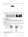
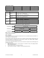
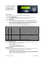
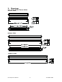
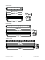
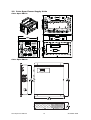
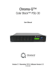
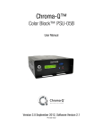
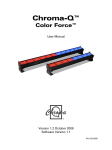
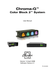
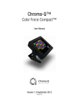
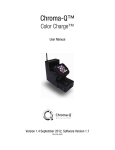
Chroma-Q™
Color Span™
User Manual
Version 2.0 March 2009
Software Version 1.6
PN: 617-0500
Disclaimer
The information contained herein is offered in good faith and is believed to be accurate.
However, because conditions and methods of use of our products are beyond our control, this
information should not be used in substitution for customer's tests to ensure that Chroma-Q
products are safe, effective, and fully satisfactory for the intended end use. Suggestions of use
shall not be taken as inducements to infringe any patent. Chroma-Q sole warranty is that the
product will meet the sales specifications in effect at the time of shipment. Your exclusive
remedy for breach of such warranty is limited to refund of purchase price or replacement of any
product shown to be other than as warranted.
The colour of the extrusion and the colour of the end plates and feet might be slightly different
because of the difference in the alloy material and the grain finish of the metal of the extrusion
and the metal end plates and feet. This is valid for any colour including clear anodising/silver.
Chroma-Q reserves the right to change or make alteration to devices and their functionality
without notice due to our on going research and development.
The Chroma-Q Color Span system has been designed specifically for the architectural lighting
industry. Regular maintenance should be performed to ensure that the products perform well in
the architectural environment.
If you experience any difficulties with any Chroma-Q products please contact your selling
dealer. If your selling dealer is unable to help please contact [email protected]. If the
selling dealer is unable to satisfy your servicing needs, please contact the following, for full
factory service:
Outside North America:
Tel: +44 (0)1494 446000
Fax: +44 (0)1494 461024
[email protected]
North America:
Tel: 416-255-9494
Fax: 416-255-3514
[email protected]
For further information please visit the Chroma-Q website at www.chroma-q.com.
Chroma-Q is a trademark, for more information on this visit www.chroma-q.com/trademarks.
The rights and ownership of all trademarks are recognised.
Color Span User Manual
1
V2.0 March 2009
Table of Contents
1.
2.
3.
Product overview …………………………………………………………………….. 3
1.1
Color Span IP20 fixture unit ………………………………………………… 3
1.2
Color Span IP67 fixture unit ………………………………………………… 4
1.3
Color Span power supply units …………………………………………….. 4
Operation ……………………………………………………………………………… 5
2.1
Unpacking the units ………………………………………………………….. 5
2.2
Cabling …………………………………………………………………………. 5
2.3
Control ………………………………………………………………………….. 6
2.4
Technical specifications ……………………………………………………… 9
2.5
Maintenance …………………………………………………………………. 10
Drawings …………………………………………………………………………….. 11
3.1
Color Span Fixture Units …………………………………………………… 11
3.2
Color Span Power Supply Units ………………………………………….. 13
Color Span PSU 2 …………………………………………………………… 13
Color Span PSU 6 …………………………………………………………… 13
Color Span User Manual
2
V2.0 March 2009
1.
Product overview
The Color Span is a configurable low profile, ultra bright LED cove lighting and wall wash
system for wide ranging applications. The fixture gives lighting designers, specifiers and end
users the flexibility to specify many aspects of its design to meet their particular application
needs, including:
IP rating:
Body length:
Body colour:
LED colours:
Optics:
Indoor (IP20) or outdoor (IP67) rated use
400mm / 16", 800mm / 32" or 1200mm / 48"
10 colours, including stock Black, White or Silver
RGBA, single colour Red, Green, Blue, Amber, Cool White, Warm White, or any
colour combination
Narrow, medium or wide beam angles
This vast range of configurations, combined with a very powerful 1500 lumens output per 1.2m
/ 4 foot and ultra slim design, makes the Color Span suitable for a wide range of wall wash,
cove, effects and feature lighting applications in the architectural and entertainment sectors.
As well as benefiting from the same high quality components and innovative LED technologies
found in other leading Chroma-Q LED products, the fixture's highly efficient solid-state
technology requires less power and maintenance compared to conventional luminaires,
enabling it to wash a 21.6m / 72 foot long wall from just a single wall outlet.
•
•
•
•
•
•
Configure the IP rating, body length, body colour, LED
colours (4 circuits) and optics
Low profile LED cove lighting and wall wash system
Ultra bright - 1500 lumens per 1.2m / 4ft
Choice of 6 & 18 way power supplies
Smooth, linear dimming curve
Optional RGBA *Magic Amber™ configuration
* Magic Amber is the term used for the unit's ability to bring in Amber when mixing
colours that require it
1.1 Color Span IP20 fixture unit
The Color Span IP20 fixtures come in lengths of 400mm / 16” with 16 high power LED, 800mm /
32” with 32 high power LED and 1200mm / 48” with 48 high power LED. Each fixture regardless
of length and number of LED shall have a total of 4 channels all the time. (See illustration below)
A fixture unit can be built to have a variety of LED colours for each of the 4 channels. The fixture
enclosure units come in custom colours and are suitable for interior applications. The highstrength extruded and anodised aluminium construction offers complete protection and houses
a discreet cable management.
Color Span User Manual
3
V2.0 March 2009
1.2 Color Span IP67 fixture unit
The Color Span IP67 fixture is a sealed enclosure made of a heavier gauge anodised aluminium
extrusion that is suitable for external applications. The units are available in custom colours, and
come in lengths of 400mm / 16” with 16 high power LEDs, 800mm / 32” with 32 high power
LEDs and 1200mm / 48” with 48 high power LEDs. Each fixture regardless of length and number
of LED shall have a total of 4 channels all the time. (See illustration below). A fixture unit can be
built to have a variety of LED colours for each of the 4 channels. (See illustration below) The
cable system for a Color Span IP67 fixture shall be customised to suit the application
requirements.
1.3 Color Span power supply units
A range of DMX controlled power supplies are available to accommodate most applications.
Each Color Span power supply features outputs via RJ45. The unit can be controlled remotely
via ANSI E1.11 USITT DMX 512-A (XLR-5 pin).
The control options incorporate the latest HSI (Hue, Saturation and Intensity), RGB(A) (Red,
Green, Blue with Magic Amber*), RGBA (Red, Green, Blue and Amber) control modes and a
dynamic variable effects engine integrated in the software which gives the lighting designer full
control over colour and effects combinations.
* Magic Amber is the term used for the unit's ability to bring in amber when mixing colours that require it
The RJ45 output connectors of the Color Span PSU units are colour coded to indicate the
appropriate Color Span fixture units.
Output Colour Coding:
Output Colour Code
Brown
Orange
Yellow
Number of LED
16
32
48
Fixture Length (in)
16
32
48
Fixture Length (mm)
400
800
1200
The Color Span PSU 2 is a power supply with 2 outputs which can be configured for up to 2 full
size (1200mm) 48 LED Colour Span fixture units, or 2 (800mm) 32 LED Color Span fixture units,
or 2 (400mm) 16 LED Color Span fixture units.
Color Span User Manual
4
V2.0 March 2009
The Color Span PSU 6 is a power supply with 6 outputs suitable for up to 6 full size (1200mm)
48 LED Color Span fixture units.
The Color Span PSU 18 is a power supply with 18 outputs suitable for up to 18 full size
(1200mm) 48 LED Color Span fixture units and fits 2U 19” rack space.
2.
Operation
2.1 Unpacking the units
The Color Span fixture package includes 1 unit Color Span and 1 pair feet support.
The Color Span PSU 2 package includes 1 unit Color Span PSU 2 and an IEC power cord.
The Color Span PSU 6 package includes 1 unit Color Span PSU 6 and an IEC power cord.
The Color Span PSU 18 package includes 1 unit Color Span PSU 18 with a 1 metre trailing lead.
2.2 Cabling
The Color Span system utilises a CAT5 cable system with an RJ45 plug to supply power and
data from the PSU to the LED fixtures. Each of the RJ45 outputs MUST supply power and data
to a total of 48 LED. Each output supports a maximum distance of 60m / 200’.
RJ45 (Pin to Pin) Wiring Diagram:
Output and Cabling Configurations
The RJ45 output connectors of the Color Span PSU units are colour coded to indicate the
appropriate Color Span fixture units.
Color Span User Manual
5
V2.0 March 2009
Output Colour Coding:
Output Colour
Brown
Orange
Yellow
Number of LED
16
32
48
Output Configurations:
PSU
Output Colour
Yellow
PSU 2
Orange
Brown
PSU 6
Yellow
PSU 18
Yellow
Fixture Length (in)
16
32
48
Fixture Length (mm)
400
800
1200
Configuration
2 outputs x (48 LED fixture)
2 outputs x (32 + 16 LED fixture)
2 outputs x (16 + 16 + 16 LED fixture)
2 outputs x (32 LED fixture)
2 outputs x (16 + 16 LED fixtures)
2 outputs x (16 LED fixtures)
6 outputs x (48 LED fixture)
6 outputs x (32 LED + 16 LED fixture)
6 outputs x (16 LED + 16 LED + 16 LED fixture)
18 outputs x (48 LED fixture)
18 outputs x (32 LED + 16 LED fixture)
18 outputs x (16 LED + 16 LED + 16 LED fixture)
Each of the RJ45 outlets of the PSU 6 and PSU 18 MUST supply 48 LEDs.
1 PSU Output
1 PSU Output
1 PSU Output
48 LED Fixture
32 LED Fixture
16 LED Fixture
16 LED Fixture
16 LED Fixture
16 LED Fixture
Note: Damage may occur to the fixture unit if it is not the appropriate size as indicated on each
output connector of the PSU.
2.3 Control
The Color Span system can operate as a stand alone unit or controlled remotely via ANSI E1.11
USITT DMX 512-A signal protocol.
The Color Span power supply units can be set to operate in various modes. Single output, and
all-grouped outputs are available with 5 control options: HSIFX, HSI, RGB(A), RGBA, RGB(A)I,
pre-programmed looks and stand-alone effects.
The Color Span PSU 2/PSU 6/PSU 18 control menu items are accessed via the LCD display and
the following controls:
•
Right hand button (Arrow) = Enter (hold for 2 seconds to save). The display flashes
before saving/recording.
•
Left hand button (Exit) = Exit without saving
•
Centre pressure slide pad = adjusts or scrolls through menu items
Color Span User Manual
6
V2.0 March 2009
The LCD Screen shown to the
right currently at the Home
position displays: Product
Name, Software Version,
current DMX Address, current
Control Mode and Time
Control menu
Use the pressure slide pad to scroll through the control menu positions:
Home / DMX Address
To set the DMX start address of the PSU 2/PSU 6/PSU 18, press Enter, scroll to
adjust DMX start address, press Enter for 2 seconds to save.
Control Mode
The PSU 2/PSU 6/PSU 18 can be set to operate in various DMX controlled modes.
The control options are HSIFx (Hue, Saturation, Intensity and Effects), HSI (Hue,
Saturation and Intensity), RGB(A) (Red, Green, Blue with *Magic Amber), RGBA (Red,
Green, Blue and Amber), RGB(A)I (Red, Green, Blue with *Magic Amber and
Intensity), pre-programmed looks and standalone effects.
Press Enter, scroll to select control mode, press Enter for 2 seconds to save.
Color Span PSU 2, PSU 6 and PSU 18 Power Supply Unit
Mode
Ch
Grouping
Description
1
61
Variable
7FX + 18 x HSI
2
54
Single
18 x HSI
3
54
Single
18 x RGB (with *Magic Amber)
4
9
All grouped
6FX + HSI
5
3
All grouped
HSI
6
3
All grouped
RGB (with *Magic Amber)
7
72
Single
18 x RGBA
8
72
Single
18 x RGBI (with *Magic Amber)
9
4
All grouped
RGBA
10
4
All grouped
RGBI (with *Magic Amber)
11
1
Any
Selection of pre-programmed looks
12
Stand-alone effects sequence
* Magic Amber is the term used for the unit's ability to bring in amber when mixing colours that require it
When DMX is Lost
If DMX is not detected various output options can be selected: Press Enter, scroll to
selection, press Enter for 2 seconds to save.
Off - will snap to off
Hold - will hold last valid DMX state
Trig - will default to Time Trigger operation
Look 1-42 - will snap to the Look of your choice
Look Store
The PSU2/PSU6/PSU18 has 42 internal FX Looks for standalone operation, 1-9 are
preset. To replay a Look, press Enter and scroll through the Looks.
Note: DMX has priority over internal Looks.
Looks can be recorded to the internal flash memory by users and will be preserved
on power down. However, looks will be returned to default setting if menu 8 Reset is
performed. There are two ways to record a look:
Color Span User Manual
7
V2.0 March 2009
1. Simple, with DMX console.
Set the PSU6/PSU18 to Control Mode 1. Use a DMX console to adjust the internal FX
engine to create the desired effect. Scroll to Look Store and press Enter, scroll to
desired Look and press Enter. Press Enter again for 2 seconds to save Look.
2. Advanced, stand alone. Set the PSU 2/PSU 6/PSU 18 to Control Mode 1.
Scroll to Look Store and press Enter, scroll to desired Look and press Enter to access
the memory data. The data is presented as two numbers separated by a letter “c”.
The number to the left of the c is the channel number and to the right is the channel
level. Scrolling the wheel will select the channel number. To edit the channel level,
press Enter to toggle to the alternate number and use the scroll wheel to adjust the
level (shown as 0-255). Press Enter to toggle back to the channel number. When the
desired effect is created press Enter for 2 seconds to save Look.
Time Triggers
The PSU2/PSU6/PSU18 has real time triggering of the internal Looks. Press Enter and
scroll to desired Time Trigger and press Enter. Press Enter to toggle between Day,
Hour (24), Minutes and Look to be triggered, adjusting the setting with the scroll
wheel as desired. Press Enter for 2 seconds to save settings. By default Time
Triggers will occur on all 7 days unless specified. The triggers will only be activated
when the feature “When DMX is Lost” is set to Trig.
Set Day and Time
Press Enter. Press Enter to toggle between Day, Hour (24) and Minutes, adjusting the
setting with the scroll wheel as desired. When the Day and Time is set correctly
press Enter for 2 seconds to save settings.
Display Backlight (Displ. Backlight)
The LCD backlight can be set to go off after 5 seconds of no activity. Press Enter,
scroll wheel to On (permanently) or Off (after 5 seconds) and press Enter for 2
seconds to save setting.
Reset to Default
Press Enter for 2 seconds to reset all menu items to factory defaults. Factory defaults
are: DMX address = 001, Control Mode = 1 (61 channels HSI+FX), DMX Lost =
Hold, Looks = default, Time Triggers deleted, Display = On.
Control options
3 channel HSI (Hue, Saturation and Intensity) gives 2 colour channels for hue and saturation and
a separate intensity channel. A separate definable intensity channel is particularly useful when
creating intensity chases or when the grand master is used. The hue channel has 255 different
colours available and the saturation channel specifies the saturation level of that colour. The
saturation channel is fully saturated at full. White is achieved with the intensity channel to full
and the saturation channel at zero.
3 channel RGB(A) (Red, Green, Blue with *Magic Amber) is the more traditional way of
controlling colour changing LED fixtures. Each of the three control channels directly affects the
intensity of the corresponding LED. Colour is mixed by adjusting the levels of the three primary
colours. White is achieved with all channels at full.
3 channel RGB(A) + 1 intensity channel (Red, Green, Blue with *Magic Amber and Intensity)
gives 3 control channels directly affecting the intensity of the corresponding LED – Red, Green,
Blue with *Magic Amber, and 1 channel affecting the intensity of all RGB(A) channels.
4 channel RGBA (Red, Green, Blue and Amber) gives 4 control channels directly affecting the
intensity of the corresponding LED – Red, Green, Blue and Amber. Colour is mixed by adjusting
the levels of each of the four colours. White is achieved with all channels at full.
Internal FX engine: modes 1 and 4 incorporate a comprehensive internal FX engine with seven
variable parameters to create an unlimited amount of unique lighting effects.
Color Span User Manual
8
V2.0 March 2009
Descriptions for the effects channels included in the following modes:
Mode 1:
Ch1 – Grouping, variable grouping facility to run FX / within groups
Ch2 – Colour Speed, variable speed of colour scrolling
Ch3 – Colour Fan, variable fan of colour between / within groups
Ch4 – Colour Range, variable limit of spectrum range for colour scrolling
Ch5 – Colour Step, variable control of smoothness of colour scrolling
Ch6 – Intensity Effects, wide selection of intensity fading and snapping effects
Ch7 – Intensity Fan, variable fan of intensity effects
Mode 4:
Ch1 – Colour Speed, variable speed of colour scrolling
Ch2 – Colour Fan, variable fan of colour between / within groups
Ch3 – Colour Range, variable limit of spectrum range for colour scrolling
Ch4 – Colour Step, variable control of smoothness of colour scrolling
Ch5 – Intensity Effects, wide selection of intensity fading and snapping effects
Ch6 – Intensity Fan, variable fan of intensity effects
* Magic Amber is the term used for the unit's ability to bring in Amber when mixing colours that require it
2.4
Technical specifications
Color Span Fixture Unit (IP20 Version)
1200mm fixture unit
800mm fixture unit
1258mm x 96mm x 54mm
852mm x 96mm x 54mm
49.6” x 3.8” x 2.1”
33.5” x 3.8” x 2.1”
Weight:
2.77kg / 6.1lbs
2kg / 4.5lbs
DMX protocol: ANSI E1.11 USITT DMX 512-A
Connectors:
RJ45
Body material: Aluminium extrusion
Body colour:
Custom
LED Heads:
48
32
Beam Angle:
12°, 18°, 40° (approx)
Lamp life:
Up to 25,000 hours
IP rating:
IP20
Operating
0ºC to 40ºC
temperature:
Approvals:
EN55103-1, EN55103-2, ICES-003/FCC PART 15
Dimensions:
400mm fixture unit
446mm x 96mm x 54mm
17.6” x 3.8” x 2.1”
1.1kg / 2.45 lbs
16
Color Span Fixture Unit (IP67 Version)
48” fixture unit
32” fixture unit
1269mm x 101mm x 62mm
862mm x 101mm x 62mm
49.9” x 4.0” x 2.5”
33.9” x 4.0” x 2.5”
Weight:
6.26kg / 13.8 lbs
4.7kg / 10.4 lbs
DMX protocol: ANSI E1.11 USITT DMX 512-A
Connectors: RJ45
Body material: Aluminium extrusion
Body colour: Custom
LED Heads:
48
32
Beam Angle: 12°, 18°, 40° (approx)
Lamp Life:
Up to 25,000 hours
IP Rating:
IP67
Operating
0ºC to 40ºC
Temperature:
Approvals:
EN55103-1, EN55103-2, ICES-003/FCC PART 15
Dimensions:
Color Span User Manual
9
16” fixture unit
456mm x 101mm x 62mm
17.9” x 4.0” x 2.5”
3.18kg / 7 lbs
16
V2.0 March 2009
Color Span Power Supply Units
Color Span PSU 2
194mm x 140mm x 127mm
7.6” x 5.5” x 5”
Weight:
2.8kg/6.2lbs
Power:
100-240V AC 50/60Hz autoswitching
Power
2.5A @ 110V AC;
consumption:
1.75A @ 230V AC
Connector in/out: RJ45
Power
IEC power cord
connector:
Control:
ANSI E1.11 USITT DMX 512-A
IP rating:
IP20
Fuses:
250V - 3A 5 x 20mm
spare included
Dimensions:
Cooling:
Approvals:
Color Span PSU 6
405mm x 362mm x 91mm
16” x 14.3” x 3.6”
9.4kg/20.6lbs
100-240V AC 50/60Hz autoswitching
7A @ 120V AC;
3.5A @ 230V AC
RJ45
IEC power cord
Color Span PSU 18
660mm x 483mm x 88mm
26” x 19” x 3.5”
22.3kg/49 lbs
100-240V AC 50/60Hz autoswitching
20A @120V AC:
10A @ 230V AC
RJ45
Trailing lead
ANSI E1.11 USITT DMX 512-A ANSI E1.11 USITT DMX 512-A
IP20
IP20
6A 20mm spare included
Both live and neutral are fused
110V - 2 x 20A 1.25” ceramic
220V - 2 x 10A 1.25” ceramic
Ventilation required front,
1 x top mounted fan,
5 x rear and 1 x side mounted
sides and top
ventilation required front and fans, ventilation required front
rear
and rear
EN55103-1, EN55103-2, ICES-003/FCC PART 15
CAN/CSA-C22.2 No.60950-1-07, UL 60950-1
2.5 Maintenance
With care, the Color Span system will require little maintenance. However, as the unit is likely
to be used in a stage environment we recommend periodical internal inspection and cleaning
of any resulting dust and cracked oil residue.
Do not spray liquids on the front or rear panel. If the front enclosure requires cleaning, wipe
with a mild detergent on a damp cloth.
Color Span User Manual
10
V2.0 March 2009
3.
Drawings
3.1 Color Span Fixture Units
400mm IP20
800mm IP20
1200mm IP20
Color Span User Manual
11
V2.0 March 2009
400mm IP67
800mm IP67
1200mm IP67
Color Span User Manual
12
V2.0 March 2009
3.2 Color Span Power Supply Units
Color Span PSU 2
MODEL: CHSPPS02
SERIAL#
AC
IN
INPUT: 100-240VAC,
50-60Hz, 3A
OUTPUT: 48VDC, 2A
USE ONLY WITH
COLOR SPAN
Replace fuse with
same type and size
!
RoHS
IN
THRU
XXXXXXX
1
2
conforms to
UL STD 60950-1
Certified to
CAN/CSA-C22.2
No.60950-1
Color Span PSU 6
Color Span User Manual
13
V2.0 March 2009
Color Span PSU 18
Color Span User Manual
14
V2.0 March 2009