1
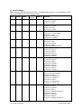
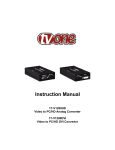
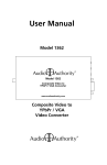
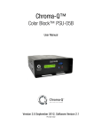
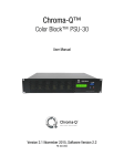
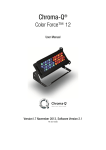
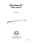
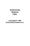
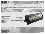
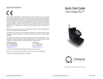
Chroma-Q™
Color Split™
User Manual
Version 1.3 September 2007
Software Version 4.0
PN: 609-0500
Disclaimer
The information contained herein is offered in good faith and is believed to be accurate.
However, because conditions and methods of use of our products are beyond our control, this
information should not be used in substitution for customer's tests to ensure that Chroma-Q
products are safe, effective, and fully satisfactory for the intended end use. Suggestions of use
shall not be taken as inducements to infringe any patent. Chroma-Q sole warranty is that the
product will meet the sales specifications in effect at the time of shipment. Your exclusive
remedy for breach of such warranty is limited to refund of purchase price or replacement of any
product shown to be other than as warranted.
Chroma-Q reserves the right to change or make alteration to devices and their functionality
without notice due to our on going research and development.
The Chroma-Q Color Split has been designed specifically for the professional entertainment
lighting industry. Regular maintenance should be performed to ensure that the products
perform well in the entertainment environment.
If you experience any difficulties with any Chroma-Q products please contact your selling
dealer. If your selling dealer is unable to help please contact [email protected]. If the
selling dealer is unable to satisfy your servicing needs, please contact the following, for full
factory service:
Outside North America:
Tel: +44 (0)1494 446000
Fax: +44 (0)1494 461024
[email protected]
North America:
Tel: 416-255-9494
Fax: 416-255-3514
[email protected]
For further information please visit the Chroma-Q website at www.chroma-q.com.
Chroma-Q is a trademark, for more information on this visit www.chroma-q.com/trademarks.
The rights and ownership of all trademarks are recognised.
Color Split User Manual
1
V1.3 September 2007
Table of Contents
1.
Product Overview ……………………..………………..…………….………........... 3
2.
Operation ……………...…………………………………..…………………….…….. 3
2.1
Unpacking the unit ………………………………..………..………………… 3
2.2
Control and power cables ………………………..………..………………… 4
2.3
Diffusion Film ………………………………………………………………….. 5
2.4
Fixing ………………………………………..…………………………………. 5
2.5
Operating the unit ………………………………………..………………….. 6
2.6
Modes of operation ………………………………………………………….. 7
2.7
Technical specifications ………………………………………………….… 10
2.8
Maintenance …………………………………………………………………. 10
2.9
Accessories ………………………………………………………………….. 11
3.
3.1
Drawings …………………………………………………………………………….. 11
Outside dimensions ………………….…………………………………………….. 11
Color Split User Manual
2
V1.3 September 2007
1.
Product overview
The Chroma-Q Color Split lighting fixture is designed specifically for professional entertainment
lighting. The fixture’s modular design shall be suitable for creating a wide range of fixture
configurations, including battens, blinders, footlights, side fills, cyclorama floods, truss toners,
discreet set piece lighting and interior architectural lighting.
Each Color Split fixture features 32 high power LEDs split into two cells which produce intense,
powerful light and vibrant colours across the across the spectrum. A 5 degree diffusion film is
integrated into one cell and a 20 degree diffusion film is integrated into the other cell.
A range of optical accessories are available to increase the flexibility of the fixture. Various
diffusers can be utilised to adjust projected beam angles and create stunning visual effects.
Designed to be intelligent both inside and out, the modular blocks incorporate the latest Hue,
Saturation and Intensity (HSI), RGB(A) with Magic amber, RGBA control modes. Variable Effects
Engine is integrated in the software which gives the lighting designer full control over colour
and effects combinations.
The products lightweight yet robust, heavy gauge aluminium extruded construction houses a
discreet cable management system and additional protection is built around the LED lenses for
a truly road proof fixture.
The Color Split has a built-in power supply with power input and through via PowerCon. The
unit can be controlled remotely through ANSI E1.11 USITT DMX 512-A.
2.
2.1
2.2
2.3
2.4
2.5
2.6
2.7
2.8
2.9
Operation
Unpacking the Unit
Control and Power Cables
Diffusion Film
Fixing
Operating the Unit
Modes of Operation
Technical Specifications
Maintenance
Accessories
2.1 Unpacking the unit
The Color Split package includes 1 unit Color Split fixture, 1 unit yoke, 2 pieces M10 x 16 knobs,
2 pieces fibre flat washers and 1 piece M10 flat washer.
Color Split User Manual
3
V1.3 September 2007
2.2 Control and Power Cables
The Color Split utilises a PowerCon cable system for power input and through and the XLR 5pin cable system for ANSI E1.11 USITT DMX 512-A data signal input and through. The XLR 5pin cables are wired pin to pin in the format shown in the table below. The chassis are ground
bonded.
XLR 5-pin cable:
Pin #
1
2
3
4
5
Power cable:
International
Colour Code
Green and Yellow
Blue
Brown
Function
Ground (-ve)
Control data minus (-)
Control data plus (+)
Spare data minus
Spare data plus
North American
Colour Code
Green
White
Black
Minimum Cable size
Screen
0.35mm² (22 AWG)
0.35mm² (22 AWG)
0.35mm² (22 AWG)
0.35mm² (22 AWG)
Connections
Earth (E)
Neutral (N)
Live (L)
Ground (Green)
Neutral (Silver)
Hot (Gold)
Important Notice: The use of an opto-splitter for DMX signal distribution is highly
recommended when several fixture units are not plugged into the same power source.
It is recommended that a maximum of 10 Color Split fixtures can be linked together utilising the
power input and through connections; data input and through connections as shown in the
illustration below.
Data Input
Data Through
Power Input
Power Through
Important Notice: The use of an opto-splitter for DMX signal distribution is highly
recommended when several fixture units are not plugged into the same power source.
Color Split User Manual
4
V1.3 September 2007
2.3 Diffusion Film
The Color Split has a 5 degree diffusion film integrated into one cell and a 20 degree diffusion
film integrated into the other cell.
Printed at the bottom plate are “chevrons” that indicate the side with the 20 degree diffusion
film.
5° Diffusion Film on this side
20° Diffusion Film on this side
2.4 Fixing
The Color Split is supplied with a detachable yoke for a single fixture which can be used for
floor mounting, direct wall mounting and truss mounting.
The Color Split features an integral connection system to enable up to 3 units locked together
as a batten or strip. Integral M10 clinch nuts are built into each end of the fixture which can be
used to attach the fixture to a standard hook clamp or the wide range of Color Split mounting
accessories.
Note:
• For the M10 nuts, ensure that the bolt is not too long to avoid damage.
• Secure each fixture with the safety bond. Provision for a fixing hold is built into the end
plate of each fixture for secondary fixings.
• Ensure adequate ventilation to the rear of all Color Split fixtures. Avoid placing the fixtures
directly on the floor pointing upwards which leaves very little space for ventilation.
Integrated Connection System
One end plate of the Color Split fixture features two protruding locating pins and a catch plate,
and the other end plate of each fixture has two keyhole slots and a butterfly latch.
1.
To connect two fixtures together, firstly mate the four protruding pins from one fixture
into the keyhole slots of the other fixture.
2.
Then slide the fixtures together so that they are aligned correctly, taking care to get past
the extended catch plate.
Note: This will be stiff on new fixtures and a twisting action may ease assembly.
Color Split User Manual
5
V1.3 September 2007
3.
Finally, use the butterfly latch to secure the fixtures together tightly (maximum of 3 units
together).
Yoke Kit
The Color Split fixture is supplied with a detachable yoke kit for a single fixture with fibre
washers and thumb wheels. An M10 flat washer is provided as a spacer for the side with
protruding pins. The yoke kit can be used for floor mounting, direct wall mounting and truss
mounting when used with hook clamps or half couplers.
Note: See Drawing on page 12.
2.5 Operating the Unit
The Color Split is controlled via a built-in addressable ANSI E1.11 USITT DMX 512-A power
supply. Control functions are accessed through the LCD display at the rear plate with 3 pushbutton switches.
Push button operation:
Control
Red Button
Black Button
Blue Button
3 digit display
Function
Mode access, enter and record
Down - Decreases (-) the mode level or value
Up - Increases (+) the mode level or value
Displays mode, monitor or blank display
Display operation:
Power-Up Display
On power-up, the display shows the software version ‘u04’ and the DMX address.
Monitor Display
If control buttons are left undisturbed for 5-7 seconds, the display will revert to ‘Monitor Mode’
The first vertical bar indicates that there is DC power unit.
The second vertical bar indicates that there is Data (DMX).
The horizontal bars indicate the Data Signal Level of first
DMX channel:
0 - 24%
No bars
25 – 49% 1 Bar
50 – 74% 2 Bars
75 – 100% 3 Bars
Display Mode
The display can be set to auto-blackout 5 seconds after it goes to ‘Monitor Mode’. Press ENTER
(red) and UP (blue) or DOWN (black) buttons to select ‘dP’ mode, then select ‘dp1’ to turn ON
the auto-blackout or ‘dP0’ to turn OFF the auto-blackout.
Default Settings:
'Factory' default settings
Reset
Press and hold for 1 second, the UP (blue) and DOWN (black) buttons to reset the unit to the
factory default settings. The display will show ‘rSt’ when UP and DOWN buttons are pressed
and after 1 second it changes to ‘don’.
Color Split User Manual
6
V1.3 September 2007
The Factory default settings put the unit in its normal operating mode.
DMX Address = 001
Display = dP0
Mode = oP1
Effects = F05, c26
'User' default settings
Each time the RED record button is pressed, the unit will save that change and these 'user
defaults' will take precedence on the next power cycle.
2.6 Modes of operation
The Color Split fixture features 32 high power LEDs divided into 2 separate cells of 16 LEDs
each. The LEDs in both cells can be controlled together as one (single control) and individually
as two separate cells (dual control).
Note: *Magic Amber is the term used for the unit's ability to be controlled with 3 channels and
include Amber when mixing the colours.
a. Control Modes
Mode 1 ‘oP1’: Single control (for 2 cells x 16 LEDs) in 3 channel RGB(A) (with *Magic Amber) is
the traditional way of controlling intensity channels of the fixture. Each of the 3 control channels
directly affects the intensity of the corresponding LED – Red, Green and Blue (with Magic
amber). Colour is mixed by adjusting the levels of the three primary colours. White is achieved
with all channels at full.
Mode 2 ‘oP2’: Single control (for 2 cells x 16 LEDs) in 4 channel RGBA: gives 4 control channels
directly affecting the intensity of the corresponding LED – Red, Green, Blue and Amber. Colour
is mixed by adjusting the levels of each of the four colours. White is achieved with all channels
at full.
Mode 3 ‘oP3’: Single control (for 2 cells x 16 LEDs) in 3 channel HSI (Hue, Saturation and
Intensity) and 2 channels for Effects: gives 2 colour channels for hue and saturation, 1 separate
intensity channel, 1 channel for colour roll speed and 1 channel for colour range. A separate
definable intensity channel is particularly useful when creating intensity chases or when the
grand master is used. The hue channel has 255 different colours available and the saturation
channel specifies the saturation level of that colour. The saturation channel is fully saturated at
full. White is achieved with the intensity channel to full and the saturation channel at zero.
Colour Roll Speed: 0% - Off; 100% - Fastest
Colour Range: 0% - Full Colour Spectrum; 67% - 1/3 Colour Spectrum
Mode 4 ‘oP4’: Single control (for 2 cells x 16 LEDs) in 3 channel RGB(A) (with *Magic Amber), 1
channel for Master Intensity and 1 channels for Effects: gives 3 control channels directly
affecting the intensity of the corresponding LED – Red, Green, Blue (with Magic Amber), 1
channel for intensity effects and 1 channel for master intensity control.
The first channel sets intensity effect and speed:
0-24%
fade on/fade off
25-49% fade on/snap off
50-74% snap on/fade off
75-100% strobe
Mode 5 ‘oP5’: Dual control (for 2 cells x 16 LEDs) in 6 channel RGB(A) (with *Magic Amber):
gives 2 sets of the 3 control channels for each cell directly affecting the intensity of the
corresponding LEDs – Red, Green and Blue (with Magic amber). Colour is mixed by adjusting
the levels of the three primary colours. White is achieved with all channels at full.
Mode 6 ‘oP6’: Dual control (for 2 cells x 16 LEDs) in 8 channel RGBA: gives 2 sets of 4 control
channels for each cell directly affecting the intensity of the corresponding LED – Red, Green,
Blue and Amber. Colour is mixed by adjusting the levels of each of the four colours. White is
achieved with all channels at full.
Color Split User Manual
7
V1.3 September 2007
Mode 7 ‘oP7’: Dual control (for 2 cells x 16 LEDs) in 6 channel HSI and 2 channel for Effects:
gives 2 sets of 2 colour channels for hue and saturation, 2 sets of separate intensity channels, 1
channel for colour roll speed and 1 channel for colour range.
Colour Roll Speed: 0% - Off; 100% - Fastest
Colour Range: 0% - Full Colour Spectrum; 67% - 1/3 Colour Spectrum
In this mode, various split colour wave effects can be created within a selected range of colours.
Set DMX-Ch2 @ any value greater than 0, and set DMX-Ch3 @ 0 or greater than DMX-Ch6 to
create two cells rolling in the opposite direction and therefore creating colour waves in the
assigned range of colours.
Example:
To create a blue to green wave effect: set DMX-Ch2 @ 67%, DMX-Ch3 @ 0%, and DMX-Ch6 @
33%, set desired speed on DMX-Ch1 and set DMX-Ch4, Ch5, Ch6, Ch7,Ch8 @ 100%.
Mode 8 ‘oP8’: Dual control (for 2 cells x 16 LEDs) in 6 channel RGB(A) (with ∗Magic Amber), 2
channel for Master Intensity and 1 channels for effects: gives 2 sets of 3 control channels
directly affecting the intensity of the corresponding LED – Red, Green, Blue (with Magic amber),
1 channel for intensity effects and 2 channels for master intensity control.
The first channel sets intensity effect and speed:
0-24%
fade on/fade off
25-49% fade on/snap off
50-74% snap on/fade off
75-100% strobe and speed
Mode 9 ‘oP9’: Stand-alone provides ‘F00 –F99’ steps for variable selection of pre-programmed
effects. The ‘F’ setting is accessible only in ‘oP9’.
‘F00-F09’ 10 speeds full colour roll
‘F10-F19’ 10 speeds cold colour roll
‘F20-F29’ 10 speeds warm colour roll
‘F30-F39’ 10 speeds magenta colour roll
‘F40-F45’ 6 fixed split colours
‘F46-F69’ 24 fixed solid colours, 4 levels of saturation for each colour: blue, cyan, green,
yellow, red and magenta
‘F70-F79’ 10 fixed white colours: 2600K, 3200K, 3600K, 4100K, 5000K, 5600K, 6500K, 7000K,
7500K, 8000K
‘F80-F84’ 5 speeds fade on/fade off
‘F85-F89’ 5 speeds fade on/snap off
‘F90-F94’ 5 speeds snap on/fade off
‘F95-F99’ 5 speeds strobe
Colour Selection of intensity effects ‘c00 to c29’ is accessed when value is between F80 – F99.
Note: In this mode, the DMX level indicator stays off.
Demo Mode ‘oP-’: is a pre-programmed sequence of the following (5 seconds for each
interval):
Start with 3 solid colours: cyan, yellow and magenta;
3 split colours are added;
Partial colour rolls start from the split colours;
Full colour roll;
Cold colour roll;
Warm colour roll;
Fade on/fade off;
Fade on/snap off;
Medium strobe;
Fast strobe.
Note: In this mode, the DMX level indicator stays off.
Color Split User Manual
8
V1.3 September 2007
b. Control Menu
Note: Press the ENTER (red) and UP (blue) or DOWN (black) button to move between modes
and press ENTER to record any changes made.
Mode
Display
Name
1
oP1
RGBhA
Cell
Control
Single
2
oP2
RGBA
Single
4
3
oP3
HSIfx
Single
5
4
oP4
RGBhAI
Single
5
5
oP5
RGBhA
Dual
6
6
oP6
RGBA
Dual
8
7
oP7
HSIfx
Dual
8
8
oP8
RGBhAI
Dual
9
Color Split User Manual
DMX Ch
3
9
Channels
Channel 1 = Red
Channel 2 = Green
Channel 3 = Blue
Channel 1 = Red
Channel 2 = Green
Channel 3 = Blue
Channel 4 = Amber
Channel 1 = Colour Roll Speed
Channel 2 = Colour Range
Channel 3 = Hue
Channel 4 = Saturation
Channel 5 = Intensity
Channel 1 = Intensity Effects and Speed
Channel 2 = Red
Channel 3 = Green
Channel 4 = Blue
Channel 5 = Master Intensity
Channel 1 = Red 1
Channel 2 = Green 1
Channel 3 = Blue 1
Channel 4 = Red 2
Channel 5 = Green 2
Channel 6 = Blue 2
Channel 1 = Red 1
Channel 2 = Green 1
Channel 3 = Blue 1
Channel 4 = Amber 1
Channel 5 = Red 2
Channel 6 = Green 2
Channel 7 = Blue 2
Channel 8 = Amber 2
Channel 1 = Colour Roll Speed
Channel 2 = Colour Range
Channel 3 = Hue 1
Channel 4 = Saturation 1
Channel 5 = Intensity 1
Channel 6 = Hue 2
Channel 7 = Saturation 2
Channel 8 = Intensity 2
Channel 1 = Intensity Effects and Speed
Channel 2 = Red 1
Channel 3 = Green 1
Channel 4 = Blue 1
Channel 5 = Master Intensity 1
Channel 6 = Red 2
Channel 7 = Green 2
Channel 8 = Blue 2
Channel 9 = Master Intensity 2
V1.3 September 2007
9
oP9
10
oP-
Stand-Alone
Press ENTER to access ‘F00-F99’ steps; press UP (blue) or DOWN (black)
button to move between steps and press Enter to record any changes
made.
The F setting is accessible only in ‘oP9’.
‘F00-F09’ 10 speeds full colour roll
‘F10-F19’ 10 speeds cold colour roll
‘F20-F29’ 10 speeds warm colour roll
‘F30-F39’ 10 speeds magenta colour roll
‘F40-F45’ 6 fixed split colours
‘F46-F69’ 24 fixed solid colours, 4 levels of saturation for each colour: blue,
cyan, green, yellow, red and magenta
‘F70-F79’ 10 fixed white colours: 2600K, 3200K, 3600K, 4100K, 5000K,
5600K, 6500K, 7000K, 7500K, 8000K
‘F80-F84’ 5 speeds fade on/fade off
‘F85-F89’ 5 speeds fade on/snap off
‘F90-F94’ 5 speeds snap on/fade off
‘F95-F99’ 5 speeds strobe
Press ENTER when in between values F80-F99 to access Colour Selection of
intensity effects ‘c00 to c29’; and UP (blue) or DOWN (black) button to move
between colours and press Enter to record any changes made.
Demo Mode
Note: The DMX level indicator stays off in modes ‘oP9’ and ‘oP-’.
2.7 Technical specifications
Dimensions:
250mm x 136mm x 125mm
9.8” x 5.3” x 4.9”
Weight:
2.38kg / 5.25 lbs
DMX protocol:
ANSI E1.11 USITT DMX 512-A
Working Voltage:
90 – 240V AC
Power consumption:
60W
Connectors:
XLR5 in/thru, PowerCon in/thru
Body material:
Aluminum extrusion
Body colour:
Black anodised
Cooling:
1 x fan
European approvals:
Pending
North American approvals:
Pending
2.8 Maintenance
With care, the Color Split fixture will require little maintenance. However, as the unit is likely to
be used in a stage environment we recommend periodical internal inspection and cleaning of
any resulting dust and cracked oil residue.
Do not spray liquids on the front or rear panel. If the front enclosure requires cleaning, wipe
with a mild detergent on a damp cloth.
Color Split User Manual
10
V1.3 September 2007
2.9 Accessories
CHCBBK20
CHCBBK30
CHCBBK3005
CHCBBK6010
3.
20 degree beam kit for Color Block/Split
30 degree beam kit for Color Block/Split
30 x 5 degree beam kit for Color Block/Split
60 x 10 degree beam kit for Color Block/Split
Drawings
3.1 Outside dimensions
250mm / 9.8”
125mm / 4.9”
136mm / 5.3”
Color Split User Manual
11
V1.3 September 2007