1
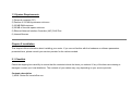
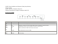
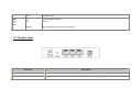
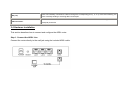
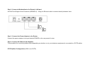
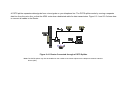
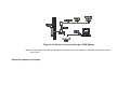
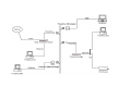
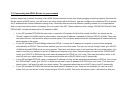
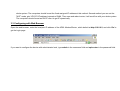
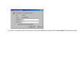
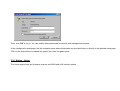
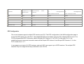
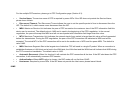
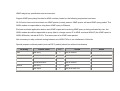
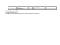
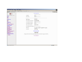
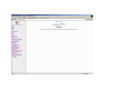
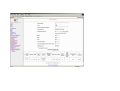
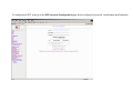
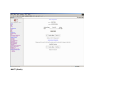
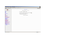
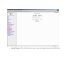
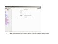
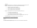
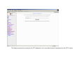
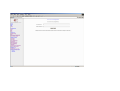
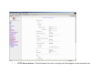
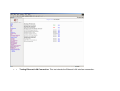
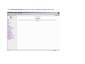
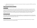
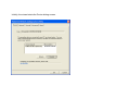
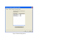
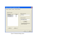
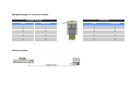
User’s Manual
for ADSL Powerline Router
Table of Contents:
FCC Part 68
FCC Part 15
Chapter 1. Introduction
Chapter 1.1 Overview
Chapter 1.2 Features
Chapter 1.3 System Requirements
Chapter 2. Installation
Chapter 2.1 Checklist
Chapter 2.2 The Front LEDs
Chapter 2.3 The Rear Ports
Chapter 2.4 Hardware Installation
Chapter 3. ADSL Configuration
Chapter 3.1 Determine your connection setting
Chapter 3.2 Connecting the ADSL Router to your network
Chapter 3.3 Configuring with Web Browser
Chapter 3.3.1 Status - Home
Chapter 3.3.2 Status - ADSL
Chapter 3.3.3 Status - LAN
Chapter 3.3.4 Status - PPP
Chapter 3.3.5 Configuration - WAN
Chapter 3.3.6 Configuration - LAN
Chapter 3.3.7 Configuration - PPP
Chapter 3.3.8 Configuration - NAT
Chapter 3.3.9 Configuration - Virtual Server
Chapter 3.3.10 Configuration - DNS
Chapter 3.3.11 Configuration - Bridge Filtering
Chapter 3.3.12 Configuration - Save Settings
Chapter 3.3.13 Configuration - Reboot Without Saving
Chapter 3.3.14 Admin Privilege - WAN Status
Chapter 3.3.15 Admin Privilege - ATM Status
Chapter 3.3.16 Admin Privilege - TCP Status
Chapter 3.3.17 Admin Privilege - Route Table
Chapter 3.3.18 Admin Privilege - Learned (Bridge) MAC Table
Chapter 3.3.19 Admin Privilege - ADSL Configuration
Chapter 3.3.20 Admin Privilege - RIP Configuration
Chapter 3.3.21 Admin Privilege - Password Configuration
Chapter 3.3.22 Miscellaneous Configuration
Chapter 3.3.23 Reset to Factory Default
Chapter 3.3.24 Diagnostic Test
Chapter 3.3.25 Code Image Update
Chapter 3.3.26 System Log
Chapter 4. Powerline Configuration
Chapter 4.1 Introduction
Chapter 4.2 Running the utility
Chapter 4.3 Device dialog screen
Chapter 4.4 Network dialog screen
Chapter 4.5 Security dialog screen
Chapter 4.6 Advanced dialog screen
Appendix A Glossary
Appendix B Cabling / Connection
Declaration of CE
FCC Part 68
This equipment complies with Part 68 of the FCC Rules. On the bottom of this equipment is a label that contains the FCC Registration
Number and Ringer Equivalence Number (REN) for this equipment. You must provide this information to the telephone company upon
request.
The REN is useful to determine the quantity of devices you may connect to the telephone line and still have all of those devices ring
when your number is called. In most, but not all areas, the sum of the REN of all devices connected to one line should not exceed five
(5.0). To be certain of the number of devices you may connect to your line, as determined by the REN, you should contact your local
telephone company to determine the maximum REN for your calling area.
If the modem causes harm to the telephone network, the telephone company may discontinue your service temporarily. If possible, they
will notify you in advance. But if advance notice isn't practical, you will be notified as soon as possible. You will be advised of your right
to file a complaint with the FCC.
The telephone company may make changes in its facilities, equipment, operations, or procedures that could affect the proper operation
of your equipment. If they do, you will be notified in advance to give you an opportunity to maintain uninterrupted telephone service.
If you experience trouble with this modem, please contact your dealer for repair/warranty information. The telephone company may ask
you to disconnect this equipment from the network until the problem has been corrected or you are sure that the equipment is not
malfunctioning.
This equipment may not be used on coin service provided by the telephone company. Connection to party lines is subject to state tariffs.
Installation
This device is equipped with a USOC RJ11C connector.
FCC Part 15
The modem generates and uses radio frequency energy. If it is not installed and used properly in strict accordance with the user's
manual, it may cause interference with radio and television reception. The modem has been tested and found to comply with the
limits for Class B computing devices in accordance with the specifications in Subpart B, Part 15 of the FCC regulations. These
specifications are designed to provide reasonable protection against such interference in a residential installation. However, there is
no guarantee that interference will not occur in a particular installation. FCC regulations require that shielded interface cables be
used with your modem.
If interference does occur, we suggest the following measures be taken to rectify the problem:
1) Move the receiving antenna.
2) Move the modem away from the radio or TV.
3) Plug the modem into a different electrical outlet.
4) Discuss the problem with a qualified radio / TV technician.
CAUTION :
Changes or modifications not expressly approved by the party responsible for compliance to the FCC Rules could void the user's
authority to operate this equipment.
Cable connections:
All equipment connected to this modem must use shielded cable as the interconnection means.
Notes:
Operation is subject to the following two conditions:
1) This device may not cause harmful interference, and
2) This device must accept any interference received including interference that may cause undesired operation.
Chapter1 Introduction
The ADSL Wireless Powerline Router can be used to bridge any Ethernet device to your wired, wireless, powerline network.
Powerline and wireless no need to spend time and money professionally installing expensive Ethernet cabling to share your Ethernet
network.
ADSL:
The ADSL Router provides home connectivity to an ADSL service provider network over an ADSL/Asynchronous Transfer Mode
(ATM) physical layer. The router can run upstream maximum transmission rates of 1Mbps and downstream maximum transmission
rates of 8Mbps. The actual rate depends on the copper category of your telephone wire, distance from the central office and the type
of ADSL service subscribed. 10/100 Base-T Ethernet Switch provided for connection to an Ethernet LAN or Ethernet-equipped PC,
and this router is easy to install and to configure.
Powerline:
The Powerline of the ADSL router fully compliant with powerline network standard . The Powerline lets you turn the existing
powerlines in your home or office into a high-speed network.
1.1 Overview
The Conexant AccessRunner CX82310 Single-Chip ADSL Router is optimised to address the growing demand for high-speed
Internet access, and it does so as a single, highly-integrated and cost-effective solution.
The CX82310 is built upon a scalable architecture and is fully compliant with full-rate ADSL (T1.413 Issue 2 and G.dmt standards)
and the splitterless ITU G.Lite (G.992.2) standards, including Annex A (ADSL over POTS) and Annex B (ADSL over ISDN). This
broad level of compliance ensures that products based on the AccessRunner can address the existing installed base and continued
deployment of ADSL lines. Telephone companies, for example, can deploy full-rate, splitterless full-rate as well as G.lite to the
consumer.
A single-chip router, the CX82310 allows an "always-on" high-speed broadband connection to the Internet. It uses existing
twisted-pair telephone lines to deliver data rates at more than 100 times the speed of conventional dial-up modems, and without the
interruptions that can plague telephone service. Data transfer rates of up to 8 Mbps downstream and 1 Mbps upstream make it the
ideal solution for high-bandwidth applications for corporate networks, Internet and video delivery.
Networking support includes both bridge and router modes. The router mode includes advanced features such as Network Address
Translation (NAT), Dynamic Host Protocol (DCHP) and Routing Information Protocol (RIPv2) processor, ADSL DMT Engine,
Analogue Front End (AFE) and Line Driver.
Through the use of a flash file system, firmware upgrades are easily managed. This allows for simple, reliable product updates or
feature enhancements.
1.2 Features
•
•
ADSL Compliance
- Compliant with ADSL standards
Full-rate ANSI.413 Issue 2 and ITU G.dmt (G.992.1) standards
Splitter less ITU G.lite (G.992.2) specification
Annex A (ADSL over POTS) and Annex B (ADSL over ISDN)
- DMT modulation and demodulation
- Full-rate adaptive modem
Maximum downstream rate of 8 Mbps
Maximum upstream rate of 1 Mbps
- Tone detection for low power mode
- Supports splitter less ADSL implementation
- Supports Dying Gasp
- Interoperable with all major DSLAM equipment
ATM Protocols
- WAN mode support: PPP over ATM (RFC 2364) and PPP over Ethernet
•
•
•
(RFC 2516)
- LAN mode support: bridged/routed Ethernet over ATM (RFC 1483) and
classical IP over ATM (RFC 1577)
- ATM Forum UNI 3.1/4.0 PVC
- Up to 8 VCs (virtual circuits)
- ATM SAR (segmentation and reassembly)
- ATM AALC (adaption layer type 5)
- OAM F4/F5
Bridge Mode
- Ethernet to ADSL self learning Transparent Bridging (IEEE 802.1D)
- Supports up to 128 MAC learning addresses
Router Mode
- IP routing-RIPv2
- Static routing
- DNS Proxy
- Port Forwarding
- DHCP (dynamic host configuration protocol) server and client
- NAT (network address translation)
- MAPT (network address and port translation)
- ICMP (Internet control message protocol)
- Simultaneous USB and Ethernet operation
Powerline Features
- Orthogonal Frequency Division Multiplexing (OFDM) with patented signal
•
•
•
processing techniques for high data reliability in noisy media conditions
- Intelligent channel adaptation maximizes throughput under harsh channel
conditions
- 56-bit DES link encryption with key management for secure
powerline communications
Security
- User authentication for PPP
- PAP (password authentication protocol)
- CHAP (challenge authentication protocol)
- Password protected system management
Ethernet Interface
- Compliant with IEEE 802.3 and 802.3u 10/100 Mbps
HTTP Web-Based Management
- Firmware upgrade via FTP
- Customizable Web pages
- WAN and LAN side connection statistics
- Configuration of static routes and routing table
- Password protected access
- Selection of bridge or router mode
- PPP user ID and password
- Configuration of VCs (virtual circuits)
1.3 System Requirements
1) Personal computer (PC)
2) Pentium II 233 MHz processor minimum
3) 32 MB RAM minimum
4) 20 MB of free disk space minimum
5) Ethernet Network Interface Controller (NIC) RJ45 Port
6) Internet Browser
Chapter 2 Installation
This chapter offers information about installing your router. If you are not familiar with the hardware or software parameters
presented here, please consult your service provider for the values needed.
2.1 Checklist
Check the shipping box carefully to ensure that the contents include the items you ordered. If any of the items are missing or
damaged, contact your local distributor. The contents of your carton may vary depending on your service provider.
Contents description
1) ADSL Router for home/office use.
2) ADSL Router Installation and Operation Guide (this publication)
3) Power adapter
4) ADSL cable RJ-11 telephone cable (6 ft)
5) Ethernet cable Ethernet category 5 twisted pair cable (6 ft)
2.2 The Front LEDs
LED
State
Description
flashing
When the router is working properly
ON
"Showtime"-successful connection between ADSL modem and telephone company's network
Flashing
"Handshaking"-modem is trying to establish a connection to telco's network
OFF
Modem is powered OFF ADSL Carrier Detect if LED is flash
Flashing
When data transmit or receive on ADSL
TP1~TP3:
ON
Ethernet link
(LAN)
Flashing
Tx or Rx activity
RDY:
ADSL:
(WAN)
ACT:
OFF
Ethernet no link
LNK:
ON
Link to powerline network
(PLC)
OFF
No link
Flashing
When data transmit or receive on powerline
ACT:
2.3 The Rear Ports
Connector
Description
POWER:
Power connector
Reset Switch
The reset button, when pressed, resets the modem without the need to unplug the power cord
LAN (1-3):
ADSL Connector:
Router is successfully connected to a device through the corresponding port (1, 2, or 3). If the LED is flashing, the
Router is actively sending or receiving data over that port.
The RJ-11 connector allows data communication between the modem and the ADSL network through a
twisted-pair phone wire
2.4 Hardware installation
This section describes how to connect and configure the ADSL router.
Step 1. Connect the ADSL Line
Connect the router directly to the wall jack using the included ADSL cable.
Step 2. Connect a Workstation to the Router's LAN port
All LAN Ports Support Auto-Crossover (MDI/MDI-X) . Using the Ethernet cable to connect directly between them.
Step 3. Connect the Power Adapter to the Router
Connect the power adapter to the port labeled POWER on the rear panel of router.
Step 4. Connect All Cables to the Network
The procedure for connecting cables differs depending on whether or not your telephone equipment is connected to a POTS splitter.
POTS Splitter Configuration (ADSL over POTS)
A POTS splitter separates data signals from voice signals on your telephone line. The POTS splitter works by running a separate
data line from the voice line, so that the ADSL router has a dedicated cable for data transmission. Figure 2-3.1 and 2-3.2 shows how
to connect all cables to the Router.
Figure 2-4.1 Router Connected through a POTS Splitter
Note: The POTS splitter may also be installed on the outside of the house adjacent to the telephone network interface
device (NID).
Figure 2-4.2 Router Connected through several micro-filters
ISDN Splitter Configuration (ADSL over ISDN)
A ISDN splitter separates ADSL signals from ISDN signals on your ISDN telephone line. The ISDN splitter works by running a separate ADSL line from the
ISDN line, so that the ADSL router has a dedicated cable for data transmission. Figure 2-3.3 shows how to connect all cables to the Router.
Figure 2-4.3 Router Connected through a ISDN Splitter
Note: The ISDN splitter may also be installed on the outside of the house adjacent to the telephone network interface
device (NID).
Powerline network connection:
Figure 2-4.4 Powerline network connection example
Chapter 3 ADSL Configuration
3.1 Determine your connection settings
Before you configure the router, you need to know the connection information supplied by your ADSL service provider.
Protocol Selection
1) PPPoE VC-Mux
2) PPPoE LLC
3) PPPoE None
4) PPPoA VC-Mux
5) PPPoA LLC
6) 1483 Bridged IP VC-Mux
7) 1483 Bridged IP LLC
8) 1483 Routed IP VC-Mux
9) 1483 Routed IP LLC
10) Classical IP over ATM
Gather the information as illustrated in the following table and keep it for reference.
PPPoE VC-Mux:
PPPoE LLC:
PPPoE None:
PPPoA VC-Mux:
PPPoA LLC:
VPI/VCI, Service Name, Username, Password, and Domain Name System
(DNS) IP address (it can be automatically assigned from ISP or be set fixed)
VPI/VCI, Service Name, Username, Password, and Domain Name System
(DNS) IP address (it can be automatically assigned from ISP or be set fixed)
VPI/VCI, Service Name, Username, Password, and Domain Name System
(DNS) IP address (it can be automatically assigned from ISP or be set fixed)
VPI/VCI, Username, Password, and Domain Name System (DNS) IP address
(it can be automatically assigned from ISP or be set fixed).
VPI/VCI, Username, Password, and Domain Name System (DNS) IP address
(it can be automatically assigned from ISP or be set fixed).
1483 Bridged IP
VC-Mux:
VPI/VCI
1483 Bridged IP LLC:
VPI/VCI
1483 Routed IP
VC-Mux:
VPI/VCI, IP address, Subnet mask, Gateway address, and Domain Name
1483 Routed IP LLC:
Classical IP over ATM:
System (DNS) IP address (it is fixed IP address).
VPI/VCI, IP address, Subnet mask, Gateway address, and Domain Name
System (DNS) IP address (it is fixed IP address).
VPI/VCI, IP address, Subnet mask, Gateway address, and Domain Name
System (DNS) IP address (it is fixed IP address).
3.2 Connecting the ADSL Router to your network
Unlike a simple hub or switch, the setup of the ADSL Router consists of more than simply plugging everything together. Because the
Router acts as a DHCP server, you will have to set some values within the Router, and also configure your networked PCs to accept
the IP Addresses the Router chooses to assign them. Generally there are several different operating modes for your applications.
And you can know which mode is necessary for your system from ISP. These modes are router, bridge, PPPoE+NAT and NAT and
PPPoA+NAT. Actually all these are for IP address of WAN.
•
•
•
•
If your ISP provides RFC1483 Routed mode, it means the IP address of LAN will be routed via WAN. You should set the
"Router" mode in the ADSL router for this situation, also set the IP address / netmask of LAN and VPI/VCI of WAN. Then save
and reboot Router, it will work fine with your whole system. The computer should be set the fixed assigned IP address with the
same domain at this mode.
If your ISP provides RFC1483 Bridge mode plus PPPoE, it means the IP address of computer or router will be assigned
automatically via PPPoE. There are two methods you can use at this mode. First you can set the "bridge" mode, give VPI/VCI
of WAN and install PPPoE driver on your computer. Then save and reboot router, it will work fine with your whole system. You
need to use Dial_Up_Network to get the IP address of computer every time. Second method you can set the "PPPoE+NAT"
mode, give VPI/VCI of WAN and set user's name & password for PPPoE on your router. Then save and reboot router, it will
work fine with your whole system. The computers should be set as DHCP client to get IP dynamically.
If your ISP provides RFC2364 mode, it means the IP address of router will be assigned automatically via PPPoA. You can set
the "PPPoA+NAT" mode, give VPI/VCI of WAN and set user's name & password for PPPoA on your router. Then save and
reboot router, it will work fine with your whole system. The computers should be set as DHCP client to get IP dynamically.
If your ISP provides RFC1483 Routed and the serial static IP address for you, there are two methods you can use at this
mode. First you can set the "router" mode and give VPI/VCI of WAN. Then save and reboot router, it will work fine with your
whole system. The computers should be set the fixed assigned IP address at this method. Second method you can set the
"NAT" mode, give VPI/VCI/ IP address /netmask of WAN. Then save and reboot router, it will work fine with your whole system.
The computers should be set as DHCP client to get IP dynamically.
3.3 Configuring with Web Browser
Open the web browser, enter the local port IP address of the ADSL Modem/Router, which default at http://10.0.0.2, and click 'Go' to
get the login page.
If you want to configure the device with administrator level, type admin in the username field and epicrouter in the password field.
If you want to configure the device with the user level, type user in the username field and password in the password field.
Then, click 'OK' to log in. You can modify these passwords for security and management purpose.
At the configuration homepage, the left navigation pane where bookmarks are provided links you directly to the desired setup page.
Click on the desired item to expand the page in the main navigation pane.
3.3.1 Status - Home
The Home page shows the firmware versions and WAN and LAN interface status.
•
Firmware Version: This field display the Conexant firm ware (vxworks.z) version number.
•
•
•
•
•
Customer Software Version: This field displays the customer' sown firmware version number and it is based on revision.txt.
WAN: These fields display the IP address, Subnet Mask and MAC address for the WAN ADSL) interface.
LAN: These fields display the IP address, Subnet Mask and MAC address for the LAN interface.
Total Number of LAN Interfaces: This field displays the total number of available interfaces for the LAN interface.
Number of Ethernet Devices Connected to the DHCP Server: These fields display the DHCP client table with the assigned
IP addresses.
3.3.2 Status - ADSL
The ADSL Status page shows the ADSL physical layer status.
•
•
Showtime Firmware Version: This field displays the Conexant ADSL data pump firmware version number.
•
•
•
•
•
•
•
•
•
ADSL Line Status: This field displays the ADSL connection process and status.
•
ADSL Modulation: This field displays the ADSL modulation status for G.dmt or T1.413.
•
ADSL Annex Mode: This field displays the ADSL annex modes for Annex A or Annex B.
•
ADSL Startup Attempts: This field displays the ADSL connection attempts after loss of showtime.
ADSL Max Tx Power: This field displays the transmit output power level of the CPE.
ADSL CO Vendor: This field displays the Central Office DSLAM vendor name, if available.
•
Elapsed Time: This field displays the time of the modem has been in operation.
•
SNR Margin: Amount of increased noise that can be tolerated while maintaining the designed BER (bit error rate). The
SNR Margin is set by Central Office DSLAM. If the SNR Margin is increased, bit error rate performance will improve, but the
data rate will decrease. Conversely, if the SNR Margin is decreased, bit error rate performance will decrease, but the data
rate will increase.
•
•
•
•
Errored Seconds: The error during Showtime, whenever, a given sec contains CRC error, that second will be declared
error second.
•
•
•
•
•
•
•
•
•
•
Line Attenuation: Attenuation is the decrease in magnitude of the ADSL line signal between the transmitter (Central
Office DSLAM) and the receiver (Client ADSL Modem), measured in dB. It is measured by calculating the difference in dB
between the signal power level received at the Client ADSL modem and the reference signal power level transmitted from the
Central Office DSLAM.
Loss of Signal: This field displays the count of event of ADSL signal loss.
Loss of Frame: This field displays the count of event of ADSL frame loss.
CRC Errors: This field displays the number of transmit data frames containing CRC errors.
Data Rate: This field displays the ADSL data rate.
Latency: This field displays the latency modes for fast or interleave.
3.3.3 Status - LAN
The LAN page shows the information and status of LAN port, DHCP client table,Ethernet link
•
LAN: These fields display the IP address, Subnet Mask and MAC address for the LAN interface.
•
•
Total Number of LAN Interfaces: This field displays the total number of available interfaces for the LAN interface.
•
Number of Ethernet Devices Connected to the DHCP Server: These fields display the DHCP client table with the
assigned IP addresses and MAC addresses.
•
•
Ethernet Link Status: This field displays the link up or down for the Ethernet.
•
3.3.4 Status - PPP
The PPP Status page shows the status of PPP for each PPP interface.
•
•
PPP: These fields display the Connection Name (user defined), Interface (PVC), Mode (PPPoE or PPPoA), Status
(Connected or Not Connected), Packets Sent, Packets Received, Bytes Sent and Byte Received.
•
•
Connect and Disconnect: This field allows the user to manually connect/disconnect the PPP connection for each PPP
interface. In another word, each PPP session can be connected and disconnected individually.
3.3.5 Configuration - WAN
The WAN configuration page allows the user to set the configuration for the WAN/ADSL ports.
Per VC Settings
•
Under Per VC Setting, it provides the configurations for VPI/VCI, Static IP Address Subnet Mask, and Gateway. The Static IP
Address, Subnet Mask and Gateway are used for Static IP configuration. Current Conexant firmware supports eight PVCs.
To switch between the PVCs, please choose the options of virtual circuit and click on the Submit button to switch over.
MAC Spoofing
•
•
The MAC Spoofing is developed to solve the scenario when the ISP only recognizes one MAC address. Copy the
ISP-recognized MAC address here.
ATM
•
•
Service Category: UBR and CBR are supported from the ATM.
Bandwidth: Bandwidth setting takes effect only when the CBR is selected. The maximum available bandwidth is from the
upstream data rate of ADSL status page (see Section 3.2, ADSL ).
Encapsulation, Bridge, PPP, and DHCP Client
WAN Configuration
Bridge Mode
Router Mode (PPPoA/PPPoE)
Router Mode
(Dynamic IP)
Router Mode (Static IP)
IP address
N/A
Automatically assigned by ISP
Automatically assigned by ISP
Provided by ISP
Subnet Mask
N/A
Automatically assigned by ISP
Automatically assigned by ISP
Provided by ISP
1483 Bridged/Routed IP
1483 Bridged IP LLC, 1483 PPPoA LLC/VC-Mux,
LLC,
Encapsulation
Bridged IP VC-Mux
1483 Bridged/Routed IP
PPPoE
1483 Bridged/Routed LLC,
1483 Bridged/Routed
LLC/VC-Mux,
VC-Mux, Classical IP over ATM
VC-Mux, Classical IP over ATM
Bridge
Enabled
Disabled
Disabled
Disabled
PPP Service
N/A
Provided by ISP
N/A
N/A
PPP User name
N/A
Provided by ISP
N/A
N/A
PPP Password
N/A
Provided by ISP
N/A
N/A
DHCP Client enable
Unchecked
Unchecked
Checked
Unchecked
PPP Configuration
The current release supports multiple PPP sessions per PVC. The PPP configuration in the WAN configuration page is
for the first PPP session for each PVC. The predefined PPP Account Name (Account ID) is Simple PPP Account 0¨ for
PVC0 and predefined PPP Connection Name is Simple PPP Session 0¡¨ for PVC0. For the other PVC X, the
predefined account name and connection name will be Simple PPP Account X and Simple PPP Session X. X is the
PVC number from 1 to 7.
It can support up to total of 16 PPP sessions, and each PVC can support up to 8 PPP sessions. The multiple PPP
sessions may be configured with any combination over 8 PVCs.
For the multiple PPP sessions, please go to PPP Configuration page (Section 6.3).
•
Service Name: The service name of PPP is required by some ISPs. If the ISP does not provide the Service Name,
please leave it blank.
•
•
Disconnect Timeout: The Disconnect Timeout allows the user to set the specific period of time to disconnect from the
ISP. The default is 0, which means never disconnect from the ISP.
•
•
•
•
MTU: Maximum Transmission Unit indicates the network stack of any packet is larger than this value will be fragmented
before the transmission. During the PPP negotiation, the peer of the PPP connection will indicates its MRU and will be
accepted. The actual MTU of the PPP connection will be set to the smaller one of MTU and the peers MRU. The default is
value 1492.
•
•
•
•
Automatic Reconnect: When it is checked, it will maintain the PPP connection all the time. If the ISP shut down the PPP
connection, it will automatically reconnect PPP session.
•
•
•
•
IGMP
•
MRU: Maximum Receive Unit indicates the peer of PPP connection the maximum size of the PPP information field this
device can be received. The default value is 1492 and is used in the beginning of the PPP negotiation. In the normal
negotiation, the peer will accept this MRU and will not send packet with information field larger than this value.
MSS: Maximum Segment Size is the largest size of data that TCP will send in a single IP packet. When a connection is
established between a LAN client and a host in the WAN side, the LAN client and the WAN host will indicate their MSS during
the TCP connection handshake. The default value is 1432.
Authentication: When AUTO option is chosen, the PAP mode will run first then CHAP.
Host name: Required by some ISPs. If the ISP does not provide the Host name, please leave it blank.
IGMP relay/proxy specification and environment:
Support IGMP proxy/relay function for ADSL modem, based on the following requirement and case:
On CO side, there must be at least one IGMP querier (router) present. IGMP querier will send IGMP query packet. The
ADSL modem is responsible to relay these IGMP query to Ethernet.
End-user multicast application device send IGMP report while receiving IGMP query or being activated by user, the
ADSL modem should be responsible to proxy (that is, change source IP to ADSL modems WAN IP) the IGMP report to
ADSL WAN side, include all PVCs. The same case is for IGMP leave packet.
Not necessary to relay multicast routing between two ADSL PVCs or two interfaces in LAN side.
Special purpose multicast packet (such as RIP 2 packet) should run without interference.
Rx Entity
ADSL
Ethernet
Packet Class
TTL
Action
IGMP query
1
Relay to Ethernet
IGMP report
1
Ignore
IGMP leave
1
Ignore
General Multicast IP
-
Relay to Ethernet
IGMP query
1
Ignore
IGMP report
1
Relay to all ADSL PVC
Notes
IGMP leave
1
Relay to all ADSL PVC
General Multicast IP
-
Ignore
3.3.6 Configuration - LAN
The LAN configuration page allows the user to set the configuration for the LAN port.
•
•
LAN IP Address & Subnet Mask: The default is 10.0.0.2 and 255.0.0.0. User can change it to other private IP address,
such as 192.168.1.2, and 255.255.255.0.
DHCP Server
•
•
System Allocated: The DHCP address pool is based on LAN port IP address plus 12 IP addresses. For example, the
LAN IP address is 10.0.0.2; the DHCP address pool is at the range of 10.0.0.3 to 10.0.0.14.
•
•
User Defined: The DHCP address pool is at the range of User Defined Start Address and User Defined End Address.
The maximum pool size can be 253 IP addresses: 255 total IP addresses V 1 broadcast address V 1 LAN port IP address.
•
DHCP Gateway Selection: The default setting for the DHCP Gateway Selection is Automatic¨. The user can select the User
Defined¨ to specify ¡§User Defined Gateway Address¡¨. The DHCP server will issue the User Defined Gateway Address¡¨ to
the LAN DHCP clients.
•
•
Lease time: The Lease time is the amount of time of a network user will be allowed to connect with DHCP server. If all
fields are 0, the allocated IP addresses will be effective forever.
•
•
User mode: Under the Single User mode, the DHCP server only allocates one IP address to local PC. Under the
Multiple User mode, the DHCP server allocates the IP addresses specified bye the DHCP address pool.
Ethernet Mode Setting
•
•
The Ethernet Mode configuration page allows the user to set the LAN port into Auto Sense, 100 Mbps Full Duplex, 100
Mbps Half Duplex, 10 Mbps Full Duplex or 10 Mbps Half Duplex.
3.3.7 Configuration - PPP
The PPP Configuration page allows the user to configure multiple PPP sessions for each PVC. It can support up to total of 16 PPP
sessions, and each PVC can support up to 8 PPP sessions. The multiple PPP sessions may be configured with any combination
over 8 PVCs.
•
•
Session Name: This field allows the user to enter his/her own session Name to distinguish different session for different
PPP accounts and different PVCs.
•
•
•
PVC: This field allows the user to choose the specific PVC for PPP session.
•
Service Name: The service name of PPP is required by some ISPs. If the ISP does not provide the Service Name,
please leave it blank.
•
•
Disconnect Timeout: The Disconnect Timeout allows the user to set the specific period of time to disconnect from the
ISP. The default is 0, which means never disconnect from the ISP.
•
•
•
•
MTU: Maximum Transmission Unit indicates the network stack of any packet is larger than this value will be fragmented
before the transmission. During the PPP negotiation, the peer of the PPP connection will indicates its MRU and will be
accepted. The actual MTU of the PPP connection will be set to the smaller one of MTU and the peers MRU. The default is
value 1492.
•
•
•
•
Automatic Reconnect: When it is checked, it will maintain the PPP connection all the time. If the ISP shut down the PPP
connection, it will automatically reconnect PPP session.
•
•
•
MRU: Maximum Receive Unit indicates the peer of PPP connection the maximum size of the PPP information field this
device can be received. The default value is 1492 and is used in the beginning of the PPP negotiation. In the normal
negotiation, the peer will accept this MRU and will not send packet with information field larger than this value.
MSS: Maximum Segment Size is the largest size of data that TCP will send in a single IP packet. When a connection is
established between a LAN client and a host in the WAN side, the LAN client and the WAN host will indicate their MSS during
the TCP connection handshake. The default value is 1432.
Authentication: When AUTO option is chosen, the PAP mode will run first then CHAP.
•
PPP Configuration Status will be displayed at the bottom of this page to show all the Session Names with its Adapter
(PVC number), Mode (PPPoA or PPPoE), Service Name, Account to Use (PPP Account ID), Disconnect Timeout
configuration, MRU, MTU, MSS, Authentication Mode (Auto, CHAP or PAP), and Auto Reconnect configuration.
To configure the PPP, must go to the PPP Account Configuration page first to configure Account ID, Users Name and Password.
•
•
•
•
•
•
Account ID: This field allows the user to enter his/her own account ID to distinguish different accounts.
•
User Name: Enter the PPP user name (usually provided buy the ISP).
•
Password: Enter the PPP password (usually provided buy the ISP).
•
PPP Account Configuration Status will be displayed at the bottom of this page to show all the accounts with its Account
Name and User Name. (It does not show the password.)
•
The Number of PPP Accounts: This field displays the total number of PPP Accounts is entered.
3.3.8 Configuration - NAT
The NAT Configuration page allows the user to set the configuration for the Network
Address Translation. The default setting is Dynamic NAPT. It provides dynamic
Network Address Translation capability between LAN and multiple WAN connections, and the LAN traffic is routed to appropriate
WAN connections based on the destination IP addresses and Route Table. This eliminates the need for the static NAT session
configuration between multiple LAN clients and multiple WAN connections.
When the Dynamic NAPT is chosen, there is no need to configure the NAT Session and
NAT Session Name Configuration.
NAPT (Static)
The NAPT option maps the single WAN IP addresses to many local PCs IP addresses.(1xN). It is the multiple-mapping
mechanism. For each WAN Interface, more than one local PCs can be associated with one WAN Interface. Click the
link Session Name Configuration to add the session name for WAN interface.
•
•
•
Session Name: This field allows the user to select the session from the configured NAT Session Name Configuration.
Users IP: This filed allows the user to assign the IP address to map the corresponding NAT/NAPT sessions.
Session Name Status will be displayed at the middle of this page to show the corresponding Session Name with its IP
address.
•
Number of NAT Configurations: This filed displays the total number of NAT Sessions is entered.
•
Available Sessions Status will be displayed at the end of this page to show all the Session Names with its WAN Interface.
Number of Session: This filed displays the total number of NAT Sessions Name is entered.
•
NAT (Static)
The NAT option only maps single WAN IP address to the local PC IP address. It is peer-to-peer mapping. (1x1) For
each WAN interface, only one local PC IP address can be associated with each WAN interface. Click the link Session
Name Configuration to add the session name for WAN interface.
•
•
Session Name: This field allows the user to enter his/her own session Name to distinguish different NAT session for
different interfaces among different PPP sessions and different PVCs.
•
•
•
Interface: This field allows the user to choose specific WAN Interface (PVC or PPP Session) for NAT Session.
NAT Session Name Status: This table displays at the bottom of this page to show all the NAT Session Names with its WAN
Interface.
•
Number of NAT Configurations: This filed displays the total number of NAT Sessions Name is entered.
Click the link Go back to NAT Configuration to the NAT configuration page. Select the NAT option. Select the
Session Name and assign the PC IP address, and choose the Add action. Click the Submit button and go to the Save
Settings to save this configuration.
NAT allows only one entry (User IP) per session.
NAPT allows many entries (User IPs) per session.
3.3.9 Configuration - Virtual Server
The Virtual Server Configuration page allows the user to set the configuration of Virtual Server. The Conexant firmware includes
the Free BSD version firewall. All UDP/TCP ports are protected from intrusion. If any specific local PCs need to be mapped to the
UDP/TCP port on WAN side, please input the mappings here.
•
•
Public Port: This field allows the user to enter the port number of the Public Network.
•
•
Private Port: This field allows the user to enter the port number of the Private Network. In most cases, the private port
number is same as public port number.
•
•
Host IP Address: This field allows the user to enter the private network IP address for the particular sever.
3.3.10 Configuration - DNS
The DNS Configuration page allows the user to set the configuration of DNS proxy. The Conexant firmware supports the DNS
proxy function. For the DHCP requests from local PCs, the DHCP server will set the LAN port IP as the default DNS server. Thus, all
DNS query messages will come into LAN port first. The DNS proxy on the ADSL modem recorded the available DNS servers, and
forward DNS query messages to one of DNS server.
•
•
Disable DNS Proxy: The LAN port does not process the DNS query message. For the DHCP requests from local PCs,
the DHCP server will set the user-configured preferred DNS sever or alternate DNS server whichever is available as the DNS
server. Then all DNS query messages will be directly sent to the DNS servers.
•
•
Use Auto Discovered DNS Servers Only: The DNS proxy will store the DNS server IP addresses obtained from DHCP
client or PPP into the table. And all DNS query messages will be sent to one of the dynamically obtained DNS servers.
•
•
Use User Configured DNS Servers Only: The DNS proxy will use the user-configured preferred DNS server and
alternate DNS server. And all DNS query message will be sent to one of DNS servers. Enter the DNS IP in the Preferred DNS
Server and Alternate DNS Server fields.
•
•
Auto Discovery + User Configured: The DNS proxys table has all the IP addresses of dynamically obtained and user
configured DNS servers.
3.3.11 Configuration - Bridge Filtering
The Bridge Filtering configuration page allows the user to set the configuration of IP filtering.
•
•
•
•
•
Source MAC: When the bridge filtering is enabled, enter the Source MAC address,select Block and click Add. Then all
incoming WAN and LAN Ethernet packets matched with this source MAC address will be filtered out. If the Forward is
selected, then the packets will be forwarded to the destination PC.
Destination MAC: When the bridge filtering is enabled, enter the Destination MAC address, select Block and click
Add. Then all incoming WAN and LAN Ethernet packets matched with this destination MAC address will be filtered out. If the
Forward is selected, then the packets will be forwarded to the destination PC.
•
Type: Enter the hexadecimal number for the Ethernet type field in Ethernet_II packets. For example, 0800 is for IP
protocol.
3.3.12 Configuration - Save Settings
The Save Settings page allows the user to save the new configuration to the flash and reboot the system.
When the configurations are changes via the Web pages, the new settings need to be saved into the flash, so it is
necessary to go to this Save Settings page to save and reboot the system for the changes to be taken effect.
During the Save and Reboot, the following Web page will be displayed is Your setting are being saved and the modem
is being rebooted. Please wait...
After the Save and Reboot, the following Web page will be displayed is Your setting have been saved and the modem
has rebooted.¡¨
3.3.13 Configuration - Reboot Without Saving
The Reboot Without Saving page allows the user to reboot the system without save the new configuration to the flash.
During the Reboot, the following Web page will be displayed. The modem is being rebooted. Please waiting. After the
Reboot, the following Web page will be displayed. The modem has rebooted.
3.3.14 Admin Privilege - WAN Status
The WAN Status page shows the information and status of WAN PVCs.
•
•
WAN: These fields display the IP address, Subnet Mask and MAC address for the WAN (ADSL) interface.
•
•
DHCP Release and Renew: This field allows the user to release and renew the WAN IP address in the WAN DHCP
Client Enabled (dynamic) mode.
3.3.15 Admin Privilege - ATM Status
The ATM Status page shows all the statistics information of ATM cells.
•
Reset Counters: This button allows user to reset the ATM Status counter.
3.3.16 Admin Privilege - TCP Status
The TCP Status page shows the statistics for all TCP connections.
•
Reset Counters: This button allows user to reset the TCP Status counter.
3.3.17 Admin Privilege - Route Table
The Route Table page displays routing table and allows the user to manually enter the routing entry. The routing table will display
the routing status of Destination, Netmask, Gateway, and Interface. The interface br0 means the USB interface; lo0 means the
loopback interface; and ppp1 means the PPP interface. The Gateway is the learned Gateway
Routing Table
•
•
•
•
•
•
The Gateway field of the static route entry allows users to either enter a Gateway IP address or select a Network Interface.
All user-defined routes retained in the CPE memory, regardless if they are already in the Routing Table, are displayed on the
same Route Table page.
All user defined route entries kept in the CPE memory during run time are saved to flash when the user chooses to save and
reboot the CPE. When CPE restarts, it reloads all saved user-defined routes to the CPE memory and tries to apply to the
system.
A user-defined route entry is added to the Routing Table whenever the system provides an environment that makes the route
entry applicable. It is removed from the Routing Table whenever the route entry becomes not applicable. e.g. If the route entry
Gateway is associated with a dynamic Network Interface but the connection is not established, then the route entry does not
appear in the Routing Table. When that interface comes up later, the route entry is then added.
If the selected Network Interface is static or is dynamic and the connection is already up, then the route entry appears in the
Routing Table immediately. If there is a Gateway associated with the selected Network Interface, then that Gateway IP
address appears in the Gateway field of the route entry
If the selected Network Interface is dynamic but the connection is not established, then the route entry does not appear in the
Routing Table. When the interface comes up later, the route entry is then added.
System Default Gateway Configuration
The system-wide Default Gateway now provides three options: Auto, User-selected Network Interface, and None.
•
•
•
None: This field allows the user to choose to have no Default Gateway in the CPE
Auto: This field allows the user to select the CPE to automatically decide the Default Gateway. (System Default)
User-selected Network Interface: This field allows user to select a Network Interface from a list (PVCs, PPP Sessions, USB
and LAN). This option lets the user to associate the system-wide Default Gateway to a Network Interface, static or dynamic,
and provides a way to fix the Default Gateway to a dynamic Network Interface before the interface is established.
Route Configuration
•
•
•
•
Destination: This field allows the user to enter the remote network or host IP address for the static routing.
Netmask: This field allows the user to enter the Subnet Mask for the static routing.
Gateway: This field allows the user to enter the IP address of the gateway device that allows the router to contact the remote
network or the host for Specified IP or select an Interface for the Gateway.
Manually Configured Routes: This field displays the static route entries entered by the user.
3.3.18 Admin Privilege - Learned (Bridge) MAC Table
The Learned MAC Table page shows the current learned Bridge MAC table.
•
Aging Timeout: This field allows the user to enter the update period for the MAC table.
3.3.19 Admin Privilege - ADSL Configuration
The ADSL Configuration page allows the user to set the configuration for ADSL protocols.
•
•
Trellis: This field allows the user to enable or disable the Trellis Code. By default, it is always enabled.
•
•
•
Handshake Protocol: This field allows the user to select the ADSL handshake protocol.
•
Wiring Selection: This field allows the user to enter the wiring selection for the RJ-11. Tip/Rip is the default for the board
without the inner/outer pair relay
•
•
Bit Swapping: This field allows the user to enable or disable the upstream bit swapping.
3.3.20 Admin Privilege - RIP Configuration
The RIP Configuration page allows the user to set the configuration for the system wide configuration of RIP. The actual RIP
configuration is in the RIP Per Interface Configuration.
•
•
RIP: This field allows the user to Enable or Disable the RIP session. The resulting RIP session will monitor all network
interfaces that are currently available for messages from other RIP routers.
•
•
Supplier Interval: This field allows the user to enter the Supplier Interval timer in second. This timer specifies how often RIP
sends announcements as a RIP Supplier. (Default = 30 seconds)
Expire Timeout: This field allows the user to enter the Expire timer in second. This timer specifies the expiration time of a
route. When a route has not been updated for more than ¡§expire¡¨ period of time, it is removed from the Route Table. This
route is invalidated and remains in the internal RIP Route Table. It will be included in the RIP announcements to let other
•
routers know the changes. (Default = 180 seconds)
Garbage Timeout: This field allows the user to enter the Garbage timer in second. This timer specifies how long the expired
and invalidated routes are kept in the Internal RIP Route Table before it is removed from it. (Default = 120 seconds)
RIP Per Interface Configuration
The RIP Per Interface Configuration page allows the user to set the configuration for each Interface (PVCs, PPP Sessions, USB and
LAN).
•
Interface: This field allows the user to choose the Interface (PVCs, PPP Sessions, USB and LAN), for the RIP to be
configured.
•
•
•
•
Enable: This field allows the user to Enable (Yes) or Disable (No) the specified interface for RIP.
Supplier: This field allows the user to select the Supplier Mode (RIP Transmit).
•
•
•
•
•
•
•
•
Disabled: The supplier transmit is disabled.
V1 BC: The supplier transmits in RIPv1 Broadcast.
V2 BC: The supplier transmits in RIPv2 Broadcast.
V2 MC: The supplier transmits in RIPv2 Multicast.
Listener: This field allows the user to select the Listener Mode (RIP Receive)
•
•
•
•
•
•
•
•
V1: The listener receives the RIPv1 only.
V2: The listener receives the RIPv2 only.
V1+V2: This listener receives the both RIPv1 and RIPv2.
Supplier and Listener are based on section 4.1 Compatibility Switch¨ in RFC 1723.
Current RIP Settings: This field displays the each interfaces RIP status.
3.3.21 Admin Privilege - Password Configuration
1.Admin
The Admin Password Configuration page allows the user to set the password for administrator.
The Admin password is same pas the FTP password, so it must has at least 8-characters for the FTP to work.
2.User
The User Password Configuration page allows the user to set the password for the user.
3.3.22 Miscellaneous Configuration
The Miscellaneous Configuration allows the user to set all the miscellaneous configurations.
•
•
HTTP Server Access: This field allows the user to configure the Web pages can be accessed from.
•
•
•
•
•
•
•
•
•
•
•
All: When this field is checked, it allows both WAN and LAN access to the Web pages.
•
Restricted LAN: This field allows the Web pages access from LAN side.
•
Restricted WAN Specified IP & Subnet Mask: This field allows the Web access from WAN side with a specify IP and
subnet mask.
•
HTTP Server Port: This field allows the user to specify the port of the Web access. . For example, when it is changed to
1001, the HTTP server address for the LAN side is http://10.0.0.2:1001.
•
FTP server: This field allows the user to enable or disable the FTP connection.
•
TFTP server: This field allows the user to enable or disable the TFTP connection.
•
DMZ: A DMZ (De-Militarized Zone) is added between a protected network and an external network, in order to provide an
additional layer of security. When there is a suspected packet coming from WAN, the firewall will forward this packet to the
DMZ host.
•
DMZ Host IP: The IP address of the DMZ host at LAN side.
•
DHCP Relay: If it is enabled, the DHCP requests from local PCs will forward to the DHCP server runs on WAN side. To
have this function working properly, please disable the NAT to run on router mode only, disable the DHCP server on the LAN
port, and make sure the routing table has the correct routing entry.
•
•
DHCP Target IP: The DHCP server runs on WAN side.
•
IGMP Proxy: Here is the global setting for IGMP Proxy. If it is enabled, then the enabled IGMP Proxy on WAN PVCs will
be working. Otherwise, no WAN PVC can have IGMP Proxy working on it.
•
•
PPP connect on WAN access: If it is enabled, the PPP session will be automatically established when there is a packet
wants to go out the WAN.
•
•
PPP Half Bridge: When the PPP Half Bridge is enabled, only one PC is able to access the Internet, and the DHCP
server will duplicate the WAN IP address from the ISP to the local client PC. Only the PC with the WAN IP address can
access the Internet.
3.3.23 Reset to Factory Default
The Reset to Factory Default page allows the user the reset the modem to original factory default configuration (factory.reg).
3.3.24 Diagnostic Test
The Diagnostic Test page shows the test results for the connectivity of the physical layer and protocol layer for both LAN and WAN
sides.
•
•
Testing Ethernet LAN Connection: This test checks the Ethernet LAN interface connection.
•
Testing ADSL Synchronization: This test checks the ADSL showtime. If this test returns FAIL, all other tests will be
skipped.
•
•
Test ATM OAM Segment Loop Back: This test sends ATM OAM F5 Segment loop back request cells to the CO. This
test will pass if response cell is received. Since some service providers might not support this test, it could still work even if
this test fails. If this test fails consistently and the ADSL modem seems not working, make sure the VPI and VCI are
configured correctly.
•
•
Test ATM OAM End-to-End Loop Back: This test sends ATM OAM F5 End to End loop back request cells to the CO.
This test will pass if response cell is received. Since some r service providers might not support this test, it could still work
even if this test fails. If this test return FAIL consistently and the ADSL modem seems not working, make sure the VPI and VCI
are configured correctly.
•
•
•
•
•
•
•
•
•
Test Ethernet Connect to ATM: This test checks the ATM AAL5 module is loaded correctly.
•
Test PPPoE Connection: This test checks the PPPOE connection.
•
Test PPP Layer Connection: This test checks the PPP authentication.
•
Test IP Connect to PPP: This test checks a valid IP address assigned from the service provider.
•
Ping Primary DNS: This test checks the primary DNS can be reached through ping request.
•
Query DNS for www.conexant.com: This test checks the host name can be resolved to IP address though domain
name servers
•
Ping www.conexant.com: This test checks the specified host can be reached through ping request.
3.3.25 Code Image Update
The Code Image Update page allows the user to upgrade the image code locally.
Browse the location of file, firmware.dlf or boorom.dlf file, and click the Upload to start the update.
3.3.26 System Log
The System Log page shows the events triggered by the system.
•
•
Clear Log: This field allows the user to clear the current contents of the System Log.
•
•
Save Log: This field allows the user to save the current contents of the System Log by right click HERE and select Save
Target As¡¨ to save it into a text file.
Chapter 4 Powerline Network Configuration
4.1 Introduction
The Powerline Network Configuration Utility for powerline networking enables the user to find devices on the powerline network,
measure data rate performance and ensure privacy by setting a user defined network private password.This utility gives you the
capability to set up a network password on the local device.Connected to the computer where the utility is running. It gives you as
well, through the advanced option, the capability to set up a network password remotely on other devices through the power
line.Before running this utility, make sure that a powerline device is properly installed and connected to your computer.
4.2 Running the utility
To run the utility, double click the Powerline Network Configuration Utility icon on your desktop.The wizard has five different dialog
screens options accessible through the following tabs: Device, Network, Security, Advanced and About. In the coming sections, we
will explain the purpose and the functionality of each of them.
4.3 Device dialog screen
The Device dialog screen provides a list of your powerline devices connected to the computer where the utility is running and
average data rate performance of your powerline network.
Initially, the wizard starts the Device dialog screen.
Figure 1 Initial screen when wizard is started
Once the analysis is done, a screen similar to Figure 2 appears.
In the text list box, it reports back all powerline devices found that are locally connected to the computer where the utility is running.In
most cases, one device only is listed.In case you have more, click on one of them and hit Connect. Make sure that the state box
indicates that your PC is connected to the same device. Now you are ready to manage the powerline network connected to this
device, ensure its privacy and measure its data rate performance.Press Refresh button to refresh the search of the powerline
devices connected to your computer.The progress bar will change into a status bar indicating the network average data rate.
Figure 2 Device dialog screen
4.4 Network dialog screen
The Network dialog screen provides detailed information about your powerline network. The test list box shows all powerline devices
found on your powerline network identified by their MAC addresss. A second column indicates their date rate measurements in
Mbps.
Press Scan Powerline Network button to refresh the listed information.
Figure 3 Network dialog screen
4.5 Security dialog screen
Note:
In case a powerline device in your home is not listed in the screen above, make sure that its network password has not been made
private previously with a different password than your current private network password.You can always reset a powerline network
password to a universal on by running the Configuration utility on the PC attached to this device and choose HomePlug as the
network password.
All powerline devices are shipped using HomePlug as a network password. The Security dialog screen allows you to change this
network password and set your own private password and apply it to the powerline device connected to the computer where the
utility running.Hit Restore default button to restore the original network password HomePlug and apply it locally.
Hit Set Local button to change the network password locally.
Figure 4 Security dialog screen
4.6 Advanced dialog screen
Note:
Your private network password must have between 4 and 24 characters. The password is case sensitive. The password can include
any letters of the alphabet, number or punctuation marks. Remember this password as it will be needed when adding other devices
to the network later.
The Advanced dialog screen allows you to set up a network password remotely on other powerline devices through the
powerline.Type your private network password into the Network Password text box.The other devices on the network with powerline
capabilities will have a different password printed on either the box itself. Find the passwords for all devices you want to manage and
type them one by one into the Device Password text box and hit Add. This will add the passwords to Remote Passwords text list box
and set them to the currently defined Network Password.
Note: The device must be present on the powerline in order for the password to be confirmed and added to the Remote Passwords
list.The Status indicates whether each device is successfully set to the Network Password.OK indicates success while Fail indicates
a failure.Hit Set All to apply your private network password to all devices that are listed in the Remote Passwords text list box and to
your local device connected to the computer where the utility is running as well.
Select a password and hit Remove to remove it from the list.
Figure 5 Advanced dialog screen
Appendix A Glossary
Address mask
A bit mask used to select bits from an Internet address for subnet addressing. The mask is 32 bits long and selects the network
portion of the Internet address and one or more bits of the local portion. Sometimes called subnet mask.
AAL5
ATM Adaptation Layer - This layer maps higher layer user data into ATM cells, making the data suitable for transport through the
ATM network.
ADSL
Asymmetric digital subscriber line
ATM
Asynchronous Transfer Mode - A cell-based data transfer technique in which channel demand determines packet allocation. ATM
offers fast packet technology, real time, demand led switching for efficient use of network resources.
AWG
American Wire Gauge - The measurement of thickness of a wire
Bridge
A device connects two or more physical networks and forwards packets between them. Bridges can usually be made to filter packets,
that is, to forward only certain traffic. Related devices are: repeaters which simply forward electrical signals from one cable to the
other, and full-fledged routers which make routing decisions based on several criteria.
Broadband
Characteristic of any network multiplexes independent network carriers onto a single cable. Broadband technology allows several
networks to coexist on one single cable; traffic from one network does not interfere with traffic from another. Broadcast A packet
delivery system where a copy of a given packet is given to all hosts attached to the network. Example: Ethernet.
CO
Central Office. Refers to equipment located at a Telco or service provider's office.
CPE
Customer Premises Equipment located in a user's premises
DHCP (Dynamic Host Configuration Protocol)
DHCP is software that automatically assigns IP addresses to client stations logging onto a TCP/IP network. DHCP eliminates having
to manually assign permanent IP addresses to every device on your network. DHCP software typically runs in servers and is also
found in network devices such as Routers.
DMT
Discrete Multi-Tone frequency signal modulation
Downstream rate
The line rate for return messages or data transfers from the network machine to the user's premises machine.
DSLAM
Digital Subscriber Line Access Multiplex
Dynamic IP Addresses
A dynamic IP address is an IP address that is automatically assigned to a client station (computer, printer, etc.) in a TCP/IP network.
Dynamic IP addresses are typically assigned by a DHCP server, which can be a computer on the network or another piece of
hardware, such as the Router. A dynamic IP address may change every time your computer connects to the network.
Encapsulation
The technique used by layered protocols in which a layer adds header information to the protocol data unit (PDU) from the layer
above. As an example, in Internet terminology, a packet would contain a header from the physical layer, followed by a header from
the network layer (IP), followed by a header from the transport layer (TCP), followed by the application protocol data.
Ethernet
One of the most common local area network (LAN) wiring schemes, Ethernet has a transmission rate of 10 Mbps.
FTP
File Transfer Protocol. The Internet protocol (and program) used to transfer files between hosts.
Hop count
A measure of distance between two points on the Internet. It is equivalent to the number of gateways that separate the source and
destination.
HTML
Hypertext Markup Language - The page-coding language for the World Wide Web.
HTML browser
A browser used to traverse the Internet, such as Netscape or Microsoft Internet Explorer.
http
Hypertext Transfer Protocol - The protocol used to carry world-wide-web (www) traffic between a www browser computer and the
www server being accessed.
ICMP
Internet Control Message Protocol - The protocol used to handle errors and control messages at the IP layer. ICMP is actually part of
the IP protocol.
Internet address
An IP address is assigned in blocks of numbers to user organizations accessing the Internet. These addresses are established by
the United States Department of Defense's Network Information Center. Duplicate addresses can cause major problems on the
network, but the NIC trusts organizations to use individual addresses responsibly. Each address is a 32-bit address in the form of
x.x.x.x where x is an eight- bit number from 0 to 255. There are three classes: A, B and C, depending on how many computers on the
site are likely to be connected.
Internet Protocol (IP)
The network layer protocol for the Internet protocol suite
IP address
The 32-bit address assigned to hosts that want to participate in a TCP/IP Internet.
ISP
Internet service provider - A company allows home and corporate users to connect to the Internet.
MAC
Media Access Control Layer - A sub-layer of the Data Link Layer (Layer 2) of the ISO OSI Model responsible for media control.
MIB
Management Information Base - A collection of objects can be accessed via a network management protocol, such as SNMP and
CMIP (Common Management Information Protocol).
NAT
Network Address Translation - A proposal for IP address reuse, where the local IP address is mapped to a globally unique address.
NVT
Network Virtual Terminal
PAP
Password Authentication Protocol
PORT
The abstraction used by Internet transport protocols to distinguish among multiple simultaneous connections to a single destination
host.
POTS
Plain Old Telephone Service - This is the term used to describe basic telephone service.
PPP
Point-to-Point-Protocol - The successor to SLIP, PPP provides router-to-router and host-to-network connections over both
synchronous and asynchronous circuits.
PPPoE
PPP over Ethernet is a protocol for connecting remote hosts to the Internet over an always-on connection by simulating a dial-up
connection.
Remote server
A network computer allows a user to log on to the network from a distant location.
RFC
Request for Comments - Refers to documents published by the Internet Engineering Task Force (IETF) proposing standard
protocols and procedures for the Internet. RFCs can be found at www.ietf.org..
Route
The path that network traffic takes from its source to its destination. The route a datagram may follow can include many gateways
and many physical networks. In the Internet, each datagram is routed separately.
Router
A system responsible for making decisions about which of several paths network (or Internet) traffic will follow. To do this, it uses a
routing protocol to gain information about the network and algorithms to choose the best route based on several criteria known as
"routing metrics".
routing table
Information stored within a router that contains network path and status information. It is used to select the most appropriate route to
forward information along.
Routing Information Protocol
Routers periodically exchange information with one another so that they can determine minimum distance paths between sources
and destinations.
SNMP
Simple Network Management Protocol - The network management protocol of choice for TCP/IP-based Internet.
SOCKET
(1) The Berkeley UNIX mechanism for creating a virtual connection between processes.
(2) IBM term for software interfaces that allow two UNIX application programs to talk via TCP/IP protocols.
Spanning-Tree Bridge Protocol (STP)
Spanning-Tree Bridge Protocol (STP) - Part of an IEEE standard. A mechanism for detecting and preventing loops from occurring in
a multi-bridged environment. When three or more LAN's segments are connected via bridges, a loop can occur. Because a bridge
forwards all packets that are not recognized as being local, some packets can circulate for long periods of time, eventually degrading
system performance. This algorithm ensures only one path connects any pair of stations, selecting one bridge as the 'root' bridge,
with the highest priority one as identifier, from which all paths should radiate.
Spoofing
A method of fooling network end stations into believing that keep alive signals have come from and returned to the host. Polls are
received and returned locally at either end
Static IP Addresses
A static IP address is an IP address permanently assigned to computer in a TCP/IP network. Static IP addresses are usually
assigned to networked devices that are consistently accessed by multiple users, such as Server PCs, or printers. If you are using
your Router to share your cable or DSL Internet connection, contact your ISP to see if they have assigned your home a static IP
address. You will need that address during your Router's configuration.
Subnet
For routing purposes, IP networks can be divided into logical subnets by using a subnet mask. Values below those of the mask are
valid addresses on the subnet.
TCP
Transmission Control Protocol - The major transport protocol in the Internet suite of protocols provides reliable, connection-oriented
full-duplex streams.
TFTP
Trivial File Transfer Protocol - A simple file transfer protocol (a simplified version of FTP) that is often used to boot diskless
workstations and other network devices such as routers over a network (typically a LAN).
Telnet
The virtual terminal protocol in the Internet suite of protocols - Allows users of one host to log into a remote host and act as normal
terminal users of that host.
Transparent bridging
So named because the intelligence necessary to make relaying decisions exists in the bridge itself and is thus transparent to the
communicating workstations. It involves frame forwarding, learning workstation addresses and ensuring no topology loops exist (in
conjunction with the Spanning-Tree algorithm).
UDP
User Datagram Protocol - A connectionless transport protocol that runs on top of TCP/IP's IP. UDP, like TCP, uses IP for delivery;
however, unlike TCP, UDP provides for exchange of datagrams without acknowledgments or guaranteed delivery. Best suited for
small, independent requests, such as requesting a MIB value from an SNMP agent, in which first setting up a connection would take
more time than sending the data.
UNI signaling
User Network Interface signaling for ATM communications.
Virtual Connection (VC)
A link that seems and behaves like a dedicated point-to-point line or a system that delivers packets in sequence, as happens on an
actual point-to-point network. In reality, the data is delivered across a network via the most appropriate route. The sending and
receiving devices do not have to be aware of the options and the route is chosen only when a message is sent. There is no
pre-arrangement, so each virtual connection exists only for the duration of that one transmission.
WAN
Wide area network - A data communications network that spans any distance and is usually provided by a public carrier (such as a
telephone company or service provider).
Appendix B Cabling / Connection
Network cables connect PCs in an Ethernet network Category 5, called "Cat5" for short is commonly used type of network cable
today.
Cat 5 cables are tipped with RJ-45 connectors, which fit into RJ-45 port.
Straight-through vs. Crossover Cables:
Straight-through
Crossover
Wire
Becomes
Wire
Becomes
1
1
1
3
2
2
2
6
3
3
3
1
6
6
6
2
LAN Connection:
To check LEDs light up when you finish connecting two pieces of hardware.