1
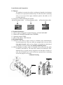
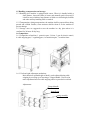
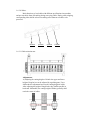
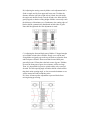
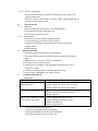
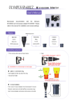
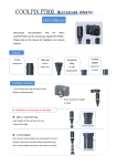
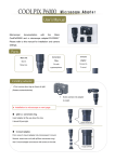
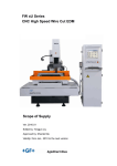
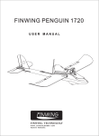
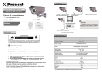
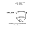
(BWS-BX30A Wire Stripper)
User Manual
Contents
Part 1: Specification and Composition……………………………………………1-7
Part 2: Operation………………………………………………………………...…..7
Part 3: Elimination and Maintenance of Common Faults………………………...…7
Part 4: Introduction to Safety……………………………………………………..…8
I. Specification and Composition:
1.1 Purposes:
The machine is extensively used for recycling used materials, the functions
of which are to separate the insulation layer of cables from their conducting
wires, so as to recycle the copper, aluminum, plastics and rubber, etc for
recycling and reuse.
1.2 Categories of cables handled by the machine
Φ13mm aluminum cables φ15mm aluminum cables
φ25mm aluminum cables
1.3 Technical Parameters:
1.3.1 Power supply voltage/power of motor/frequency: AC240V/3KW/50HZ
1.3.2 Dimension: 860mm※720mm※1150mm (L※W※H)
1.3.3 Operating weight: 220KG
1.3.4 Processing capacity: MAX 30m/min
1.4 Working principles:
1.4.1 Shaft (1) and shaft (2) rotate reversely in clockwise and counterclockwise
direction respectively. These two shafts are equipped with conveyor rollers
(four pairs in total), while two long blades are installed on both sides of
each group of conveyor rollers (see partially amplified picture).
1.4.2 While opening the machine, cables are manually conveyed between the cables
on shaft (1) and shaft (2). The rollers drive cables to be transferred. Then,
aluminum layer is ripped open by long knives on both sides of rollers, in
order that aluminum layer can be effectively separated from conducting
wire for the purpose of recycling.
Schematic Drawing
long blades
shaft (1)
shaft (2)
1.5 Handling, transportation and storage:
1.5.1 Handling: this machine is equipped with casters. When it is handled within a
short distance, loosen the brake of casters and manually push it forward. If
it shall be moved within a long distance or lifted to a certain height, forklifts
and other auxiliary handling tools are needed.
1.5.2 Transportation: during transportation, the machine shall be protected from being
pressed and collided. Besides, some measures shall be taken to fix the machine to
prevent damage.
1.5.3 Storage: users are suggested to store the machine in a dry place where it is
ventilated for 24 hours all day long.
1.6 Composition:
1.6.1 Composition of machine: 1. protective part; 2. inlets; 3. part for electric control;
4. cable stripping part; 5. regulating part; 6. transmission part; 7. machine frame
1.6.2.3 Left and right adjustment mechanism:
Main functions: uplifted height of shaft 1 can be adjusted during cable
stripping by screwing up or loosening a T-shaped handle. Users need to
make adjustment based on cable stripping effects expected to be realized.
Adjustments:
T-shaped handle
butterfly nut
spring assembly
1.6.2.10 Inlets:
Main functions: to lead cables with different specifications into machine
and prevent cables from off tracking during conveying cables. During cable stripping,
corresponding inlet shall be selected according to the diameter of cables to be
processed.
Φ13mm
φ15mm
φ25mm
φ30mm
1.6.2.11 Cable stripping part:
Adjustments:
A) Adjusting the cutting height of a blade: the upper and lower
height of long knives can be adjusted by regulating nuts. Users
shall make the adjustment based on the cutting height of cables.
After adjusting the height of long blades, they shall be parallel at
both ends. Meanwhile, the cutting height of blades generally shall
reach the center of cables.
B): Adjusting the cutting center by blades: each adjustment bolt is
fixed on angle steel by four upper and lower nuts. To adjust the
distance from the left side to right side of a blade, the nuts inside
the angle steel shall be firstly screwed off and screw bolts shall be
gently tapped, so that the cutting height of blades can exactly reach
the thickness of aluminum cover. Furthermore, the cutting edges of
blades shall be symmetrically distributed on both sides of gears.
Nuts shall be tightened after the adjustment is made.
C): Adjusting the front and back parts of blades: U-shaped troughs
are available on both sides of blades. Slowly screw off the nuts
fixing blades and gently tap on the top of blades to adjust the front
and back parts of blades. Please note that front and back parts
generally locate 0.55mm above the back center of gears. If blades
are near the front parts of gears, the resistance will be too large.
Then, it is impossible for gears to occlude cables to be conveyed
forward. The inlet opening angle of blades shall be a little smaller
than their outlet opening angle, or else too much aluminum covers
will be intertwined with conducting wires.
D): Screw all nuts up after adjustment to prevent blades from
moving during processing.
1.6.2.12 Electric control part:
The electric control part was made of electromotor, switch, power line,
plug and other parts.
The power supply of this machine: AC220V / 50Hz, use the middle line N.
User must use the guard wire PE.
1.7
Notes of test run
1.7.1 Inspection
1. Check whether the fastening piece was installed fixed.
2. The transmission part is loosened or not.
3. The electrical part is OK or not.
1.7.2 Start machine
1. Switch on power and start the stripper machine.
2. Test the stripping to select the proper feed port.
3. Adjust the up and down adjustment device to achieve the proper
stripping effect.
4. Batch stripping.
2.
Machine operation
1. Read this manual in detail before use the machine.
2. The power of this machine is AC240V; the power should be connected
right.
3. After the power is on, press “ON” to start machine.
4. Select the proper feed port to strip.
5. In the process of stripping, if the emergency happened, press “OFF”
to stop the machine.
6. Clean the remaining residue of machine after processing.
7. Place it in the ventilated dry site within 24 hours.
3.
Common fault removal
Maintenance:
Common fault
Removal method
The stripper machine didn’t 1. Check whether power was connected.
work after started.
2. Check whether the electric wire was good.
3. Check whether the motor was damaged.
The motor belt dropped.
1. Check whether the belt was OK.
2. Renew to adjust the position of motor.
3. Replace the belt.
There was abnormal sound 1. Check whether each part was OK.
after machine was started.
2. Check whether the bearing was OK.
3. Chain was OK or not.
4. Add the lubrication oil.
2.1 Clean the machine up after use it.
2.2 The bearing should be coated lubrication.
2.3 The gear and blade should be coated antirust oil.
2.4 The gear should be placed in the dry site.
4.
Security declaration
4.1
Unsafe factors:
1. There was equipped with sharp blade in this machine. In the process of
operation, if there was material blocking or unprosperous outgoing, use
hand to pick the material under the condition of running (meanwhile, the
blade was running), the body of worker would be injured.
2. The used power of this machine was 240V; it’s demanded that operator
operated according to the rules so as not to be shocked by electricity.
3. Man-made removal to protective cover and repair at the moment when the
machine was running.
4.2
Safety rules
1. The machine can’t be started arbitrarily without person who was familiar
with the performance and operation rules of this machine, it’s suggested that
the operator should read this manual carefully again and again.
2. Prohibit arbitrary dismantling the protective parts what’s related with the
machine’s safety. Before use every time, check carefully the tightness of
each part. Check whether electric part was connected well and the switch
could carry out the relevant action.
3. Prohibit arbitrary maintenance when the machine was running, if the
emergency happened, the “OFF” switch should be pressed and the
operation should be done after the power was cut off.
4. If material was blocked, shut down the machine, wear the protective gloves
and pick up the relevant assistant tools.
5. When use, note the warning mark, avoid the accident.