1
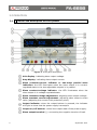
FA-665B
ADJUSTABLE DC REGULATED POWER
SUPPLY
- 0 MI2066 -
SAFETY NOTES
Read the user’s manual before using the equipment, mainly "SAFETY RULES"
paragraph.
on the equipment means "SEE USER’S MANUAL". In this manual
The symbol
may also appear as a Caution or Warning symbol.
WARNING AND CAUTION statements may appear in this manual to avoid injury
hazard or damage to this product or other property.
USER'S MANUAL VERSION
Version
1.0
Date
September 2015
SAFETY RULES
* These instruments fulfill the regulations of CE-LVD (EN-61010:2001) and CE-EMC
(EN-55022:1998/+A1:2000; EN 55024:1998; EN61000-3-2:2000; EN61000-33:1995).
* To ensure safe operation of the equipment and eliminate the danger of serious injury
due to short-circuit (arcing), the following safety precautions must be observed.
* Damages resulting from failure to observe these safety precautions are exempt
from any legal claims whatever.
* Prior to connection of the equipment to the mains outlet, check that the available
mains voltage corresponds to the voltage setting of the equipment.
* Connect the mains plug of the equipment only to a mains outlet with earth
connection.
* Do not place the equipment on damp or wet surfaces.
* Do not subject the equipment to direct sunlight or extreme temperatures.
* Do not subject the equipment to extreme humidity or dampness.
* Replace a defective fuse only with a fuse of the original rating. Never short circuit
fuse or fuse housing.
* Do not exceed the maximum permissible input rating.
* Conduct measuring works only in dry clothing and in rubber shoes, i.e. on isolating
mats.
* Comply with the warning labels and other info on the equipment.
* Do not insert metal objects into the equipment by way of the ventilation slots.
* Do not place water-filled containers on the equipment (danger of short-circuit in
case of knock over of the container).
* Do not operate the equipment near strong magnetic fields (motors, transformer
etc.).
* Do not subject the equipment to shocks or strong vibrations.
* Keep hot soldering iron or guns away from the equipment.
* Allow the equipment to stabilize at room temperature before taking up
measurement (important for exact measurement).
* Do not modify the equipment in any way.
* Do not place the equipment face-down on any table or work bench to prevent
damaging the controls at the front.
September 2015
* Opening the equipment and any service and repair work must be performed by
qualified service personal. Repair work should be performed in the presence of a
second person trained to ad minister first aid, if needed.
* Power supplies do not belong to children hands.
* Symbols related with safety:
Descriptive Examples of Over-Voltage Categories
Cat I
Low voltage installations isolated from the mains.
Cat II
Portable domestic installations.
Cat III
Fixed domestic installations.
Cat IV
Industrial installations.
September 2015
TABLE OF CONTENTS
1 INTRODUCTION ........................................................................................
1.1 Description .......................................................................................
2 OPERATION ..............................................................................................
2.1 Control and description of front pannel .................................................
2.2 Operating method..............................................................................
2.2.1 Independence use of two adjustable output .......................................
2.2.2 Series using of the two adjustable outputs ........................................
2.2.3 Parallel using of the two adjustable outputs .......................................
3 SPECIFICATIONS ......................................................................................
4 MAINTENANCE ..........................................................................................
4.1 Cleaning Recommendations ................................................................
September 2015
1
1
2
2
4
4
4
5
7
8
8
ADJUSTABLE DC REGULATED POWER SUPPLY
FA-665B
1 INTRODUCTION
1.1
Description
The model FA-665B high-precision DC regulated power supply has three ways
output. Of which, two ways are adjustable and one way is fixed.
The two adjustable outputs can also be selected for constant voltage or constant
current, designed in high stability and performance circuit. In constant voltage
state, the output voltage can be arbitrarily adjusted from 0 V on in the nominal
range; and in the state of constant current, the output current can be adjustable
from 0 A on in the nominal range. The two outputs can be connected in parallel
or in series, while the master used for voltage or current adjustment. The
maximum output voltage in series is double of independent's, and the maximum
output current in parallel is double too.
There are volt and Amp meters (LED) for indicating each of the two outputs with
high accuracy.
The one fixed way outputs 5 V voltage. Due to the single chip integrated
regulator, this output has good stability and ripple factor, and has reliable
overload protection to protect the unit against being damaged whenever
overload or short circuit.
The unit features in small size, good performance, novel appearance and etc, it is
the ideal power supply unit for science investigation, college, factory, electronic
appliance maintenance and etc.
September 2015
1
2 OPERATION
2.1
Control and description of front pannel
Figure 1. Front panel description.
Volt display: indicating slave output voltage.
Amp display: indicating slave output current.
Slave constant-current indicator or two-ways parallel state
indication: the LED illuminates when the slave output is in currentregulated state or the two adjustable outputs is in parallel.
Slave constant-voltage indicator: the LED illuminates when the
slave output is in voltage-regulated state.
Slave constant voltage adjustment: adjusting slave output voltage.
Slave constant current adjustment: adjusting slave output current
value (adjusting the current-limit protection point).
Output indicator: when the output buttom is pressed, the indicator
will light to show that the power supply has output.
Output on/off buttom: control the output state of the power supply.
Slave output terminal (-): connecting the negative termina of load.
2
September 2015
Case ground: connecting the case to ground.
Slave output terminal (+): connecting the positive terminal of load.
Master output terminal (-): connecting the negative terminal of load.
Case ground: connecting the case to ground.
Master output terminal (+): connecting the positive terminal of load.
Control switch: for selecting the two adjustable outputs independent,
series, parallel.
Fixed 5V output terminal (-): connecting the negative terminal of
load.
Fixed 5V output terminal (+): connecting the positive terminal of
load.
Power switch: the unit is ON when this button switch is depressed,
while CV LED (4) (22) or CC LED (3) (23) illuminating.
Fixed output over current indicator: the indicator will light if the
fixed output is over current.
Master constant voltage adjustment: adjusting master output
voltage.
Master constant current adjustment: adjusting master output
current value (adjusting the current-limit protection point).
Master constant-voltage indicator: the LED illuminates when the
master output is in voltage-regulated state.
Master constant-current indicator: the LED illuminates when the
master output is in current- regulated state.
Volt display: indicating master output voltage.
Amp display: indicating master output current.
September 2015
3
2.2
2.2.1
Operating method
Independence use of two adjustable output
Set switchs (15) to spring out position.
When the adjustable output is used as CV output, first should rotate
clockwise the CC adjustment (6) and (21) to maximum, then turn on
power switch (18), adjust CV adjustment (5) and (20) till output voltage
reach required voltage value. At this time, the CC state indicator (3) and
(23) go out and the CV state indicator (4) and (22) light on.
Used as CC output, after turning on power switch (18), first rotate
clockwise the CV adjustment (5) and (20) to maximum, while rotate
counterclockwise the CC adjustment (6) and (21) to minimum, then
connect the required load, again adjust clockwise adjustment (6) and
(21) till output current reach the required current value. At this time, the
CV state indicator (4) and (22) go out and the CC state indicator (3) and
(23) light on.
Used as the CV output, in general the CC adjustment (6) and (21) should
be set to maximum, but for this unit, the current-limiting protection point
can also be set arbitrarily.
Setting procedure: turn on power, rotate counterclockwise the CC
adjustment (6) and (21) to minimum, then make the positive and
negative output terminal in short connection and rotate clockwise the CC
adjustment (6) and (21) till output current equal to the required currentlimiting protection point, so the current-limiting protection point is well
set.
2.2.2
Series using of the two adjustable outputs
Set Switchs (15) in series mode according to the front panel. At this
time, turn the master voltage adjustment (20) and the slave out voltage
tracks strictly the master output voltage, and the output voltage can be
up to double of independent's maximum voltage (voltage between
terminal (14) and (9)).
Before the series connecting, it must be examined if the negative
terminal of both master and slave output are connected to case grounded
terminal, if they are, must be disconnect, otherwise, short-circuit will be
caused in the slave output when the two outputs are connected is series.
4
September 2015
When the two outputs are in series, the voltage is controlled by master
output, but current adjustment of two outputs is still independent.
Therefore, attention should be paid to the position of the CC adjustment
(6). For example, knob (6) is at the position of counterclockwise to end
or current of slave output excesses current-limiting protection point, at
this time, the voltage of slave output will not track the voltage of master.
So knob (6) should be rotated clockwise to maximum then the two
outputs are in series.
By series connection, if there is power output, proper leads corresponding
to output power should be used to short connect the negative terminal of
master output with positive terminal of slave output reliably. Since it is
shorted by a switchinside the unit, current will pass on the shorted
switch when there is power output. This will affect the reliability of the
unit.
2.2.3
Parallel using of the two adjustable outputs
Press in switchs (15) , at this time, the two output are in parallel, adjust
voltage adjustment (20) of master output, the voltage of two ways keep
same, and slave output CC indicator (3) lights on.
When the two outputs are in parallel, the CC adjustment (6) of slave
output does not work. When used as CC supply, simply adjust the CC
adjustment (21) of master output, at this time, output current of both
master and slave are controlled by it and are same, output current is up
to double of independent's maximum current.
While the two outputs in parallel, proper leads corresponding to output
power should be used to short reliably the two positive terminal and the
Two negative terminals of master, slave output separately, so as to make
load connected reliably with the two parallel outputs. If the load is only
connected to one of the output terminals, unbalance may be caused to
current of the two outputs, this may also damage the series/ parallel
switchs (15).
NOTE:
The LED display is in three digits. To get more accurate measuring value, you
should calibrate by external circuit with precision measuring instrument.
September 2015
5
CAUTION: This unit has excellent protection function, 5V output has
reliable protection for current-limit and short. The two
adjustable outputs have current-limit protection. As there is
controlling circuit for regulating transistor's power loss in
the circuit, when short-circuit occurs, the power loss on
large power transistors is not very high, it can't cause any
damage to the unit. But there is still power loss when
short-circuit, in order to reduce aging and energy
consumption, so this situation should be found as soon as
possible and turn off power, then exclude the faults.
When operating is finished, put it in a dry place of good
ventilation, and keep it clean. If it is not in use for a long
period, pull off the power supply plug for storage.
For maintenance, input voltage must be cut off.
6
September 2015
3 SPECIFICATIONS
Specifications
Input voltage
Output voltage
Output current
Line regulation
Two adjustable output
Fixed output
Load regulation
Two adjustable outputs
Fixed output
Ripple and noise
Two adjustable output
Fixed output
Protection
Display accuracy
Volt-indication
Amp-indication
Mechanical features
Dimensions W. x H. x D.
Weight
110 VAC~127 VAC x 10 % / 60 Hz
220 VAC~240 VAC x 10 % / 50 Hz (switchable)
2 x 0 to 30 V
0 to 5 A
CV = 1 x 10 -4 + 3 mV
CC = 2 x 10 -3 + 3 mA
10 mV
CV = 1
CV = 1
CC = 2
CC = 2
10 mV
x
x
x
x
10-4
10-4
10-3
10-3
+
+
+
+
2
5
3
5
mV
mV
mA
mA
CV = 0.5 mV rms
CV = 1.0 mV rms
CC < 3mA rms
10 mV rms
Current-limit
(0.2%Rdg+2 digits), 2.5% Full Scale
(1.0%Rdg+2 digits), 2.5% Full Scale
260 x 160 x 340
10 kg
Accesories
1 x Quick Reference Guide
2 x Fuses
Note: Equipment specifications are set in these environmental operating conditions. Operation
outside these specifications are also possible. Please check with us if you have specific
requirements.
RECOMMENDATIONS ABOUT THE PACKING
It is recommended to keep all the packing material in order to return the equipment, if
necessary, to the Technical Service.
September 2015
7
4 MAINTENANCE
4.1
8
Cleaning Recommendations
CAUTION:
To clean the cover, take care the instrument is disconnected.
CAUTION:
Do not use scented hydrocarbons or chlorized solvents. The
cover should be cleaned by means of a light solution of
detergent and water applied with a soft cloth. Dry thoroughly
before using the system again.
CAUTION:
Do not use for the cleaning alcohol or its derivatives, these
products can attack the mechanical properties of the materials
and diminish their useful time of life.
September 2015
PROMAX ELECTRONICA, S. L.
Francesc Moragas, 71-75
08907 L’HOSPITALET DE LLOBREGAT (Barcelona)
SPAIN
Tel. : 93 184 77 00 * Tel. Intl. : (+34) 93 184 77 02
Fax : 93 338 11 26 * Fax Intl. : (+34) 93 338 11 26
http://www.promaxelectronics.com
e-mail: [email protected]