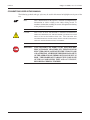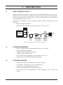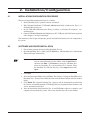
1
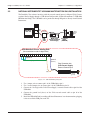
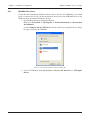
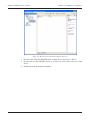
Durability Test 1.0
Software
User’s Manual
Purchase Record
Please record all model numbers and serial numbers of your
Magtrol equipment, along with the general purchase information.
The model number and serial number can be found on either
a silver identification plate or white label affixed to each unit.
Refer to these numbers whenever you communicate with a
Magtrol representative about this equipment.
Model Number:
_____________________________
Serial Number:
_____________________________
Purchase Date:
_____________________________
Purchased From:
_____________________________
While every precaution has been exercised in the compilation of this document to
ensure the accuracy of its contents, Magtrol, Inc. assumes no responsibility for errors or
omissions. Additionally, no liability is assumed for any damages that may result from the
use of the information contained within this publication.
COPYRIGHT
Copyright ©2007 Magtrol, Inc. All rights reserved.
Copying or reproduction of all or any part of the contents of this manual without the
express permission of Magtrol is strictly prohibited.
TRADEMARKS
National Instruments™ and NI-DAQ™mx are trademarks of National Instruments
Corporation.
Microsoft® and Windows® are registered trademarks of Microsoft Corporation.
Pentium® is a registered trademark of Intel Corporation.
First Edition – December 2007
Safety Precautions
1. Make sure that all Magtrol brakes and electronic products are earth-grounded, to ensure personal
safety and proper operation.
2. Check line voltage before operating electronic equipment.
3. Make sure that brakes and motors under test are equipped with appropriate safety guards.
i
Revisions To This Manual
The contents of this manual are subject to change without prior notice. Should revisions be necessary, updates to all
Magtrol User’s Manuals can be found at Magtrol’s web site at www.magtrol.com/support/manuals.htm.
Please compare the date of this manual with the revision date on the web site, then refer to the manual’s Table of
Revisions for any changes/updates that have been made since this edition.
REVISION DATE
First Edition – December 2007. Corresponds to revision 7.12.4 and later versions of Durability Test Software.
TABLE OF REVISIONS
Date
12/21/07
Edition
1st Edition
Change
New "dual" program option allows user to control two test
setups from one PC.
ii
Section(s)
1.3, 2.3.1, 4.1,
4.6
Table of Contents
SAFETY PRECAUTIONS.......................................................................................................................... I
REVISIONS TO THIS MANUAL................................................................................................................ II
REVISION DATE.................................................................................................................................................................. II
TABLE OF REVISIONS....................................................................................................................................................... II
TABLE OF CONTENTS........................................................................................................................... III
TABLE OF FIGURES..........................................................................................................................................................IV
PREFACE.................................................................................................................................................. V
PURPOSE OF THIS MANUAL........................................................................................................................................... V
WHO SHOULD USE THIS MANUAL................................................................................................................................ V
MANUAL ORGANIZATION............................................................................................................................................... V
CONVENTIONS USED IN THIS MANUAL.....................................................................................................................VI
1. INTRODUCTION.................................................................................................................................. 1
1.1
1.2
1.3
ABOUT DURABILITY TEST 1.0.............................................................................................................................. 1
SYSTEM REQUIREMENTS...................................................................................................................................... 1
SOFTWARE FEATURES............................................................................................................................................ 1
2. INSTALLATION/CONFIGURATION..................................................................................................... 2
2.1
2.2
2.3
INSTALLATION/CONFIGURATION PROCEDURE............................................................................................... 2
SOFTWARE AND DRIVER INSTALLATION.......................................................................................................... 2
NATIONAL INSTRUMENTS™ USB-6008 MULTIFUNCTION DAQ INSTALLATION................................................3
2.3.1 NI-DAQmx Device Setup.............................................................................................................................. 4
3. SOFTWARE INTERFACE.................................................................................................................... 6
3.1
3.2
STARTUP.................................................................................................................................................................... 6
DURABILITY TEST WINDOWS.............................................................................................................................. 6
3.2.1 Setup.............................................................................................................................................................. 6
3.2.2 Run................................................................................................................................................................ 6
3.2.3 Results........................................................................................................................................................... 6
4. TEST SETUP........................................................................................................................................ 7
4.1
4.2
4.3
4.4
4.5
4.6
4.7
4.8
4.9
TEST SETUP WINDOW............................................................................................................................................ 7
LOAD PROFILE......................................................................................................................................................... 7
NUMBER OF PROFILE CYCLES............................................................................................................................. 7
CURRENT SUPPLY................................................................................................................................................... 8
CALIBRATE CURRENT SUPPLY............................................................................................................................ 8
CURRENT SUPPLY CONTROL INTERFACE DEVICE......................................................................................... 9
4.6.1 View Wiring Setup Diagram.......................................................................................................................... 9
PROFILE DEFINITION............................................................................................................................................ 10
SAVE PROFILE......................................................................................................................................................... 10
RUN TEST................................................................................................................................................................. 10
5. TEST RUN.......................................................................................................................................... 11
5.1
5.2
5.3
CURRENT VS. TIME GRAPH................................................................................................................................. 11
PROFILE CYCLE..................................................................................................................................................... 11
CURRENT LEVEL................................................................................................................................................... 11
iii
Table of Contents
Magtrol Durability Test 1.0 Software
6. TEST RESULTS................................................................................................................................. 12
6.1
6.2
6.3
TEST RESULT.......................................................................................................................................................... 12
RUN ANOTHER TEST............................................................................................................................................. 12
EXIT PROGRAM...................................................................................................................................................... 12
SERVICE INFORMATION....................................................................................................................... 13
RETURNING MAGTROL EQUIPMENT FOR REPAIR AND/OR CALIBRATION....................................................... 13
Returning Equipment to Magtrol, Inc. (United States).............................................................................................. 13
Returning Equipment to Magtrol SA (Switzerland).................................................................................................. 13
TABLE OF FIGURES
1. INTRODUCTION
Figure 1–1 Durability Test 1.0 System Configuration..................................................................................................1
2. INSTALLATION/CONFIGURATION
Figure 2–1 USB-6008 Wiring Diagram.......................................................................................................................3
Figure 2–2 New Data Acquisition Device Dialog Box................................................................................................4
Figure 2–3 Measurement & Automation Explorer Interface.......................................................................................5
4. TEST SETUP
Figure 4–1
Figure 4–2
Figure 4–3
Figure 4–4
Figure 4–5
Setup Window(s)........................................................................................................................................7
Current Range Window..............................................................................................................................8
Calibration Window...................................................................................................................................8
Wiring Setup Diagram...............................................................................................................................9
Save Profile Dialog Box..........................................................................................................................10
5. TEST RUN
Figure 5–1 Run Window.............................................................................................................................................11
6. TEST RESULTS
Figure 6–1 Results Window........................................................................................................................................12
iv
Preface
PURPOSE OF THIS MANUAL
This manual contains information required for installation and general use of Magtrol’s Durability
Test 1.0 Software. To achieve maximum capability and ensure proper use, please read this manual
in its entirety before operating. Keep the manual in a safe place for quick reference whenever a
question should arise.
WHO SHOULD USE THIS MANUAL
This manual is intended for those operators in need of a software program to complement their
Magtrol test equipment setup. The setup may include the following Magtrol products:
• HB or AHB Series Hysteresis Brakes
• Model 5210 Current-regulated Power Supply
MANUAL ORGANIZATION
This section gives an overview of the structure of the manual and the information contained within it.
Some information has been deliberately repeated in different sections of the document to minimize
cross-referencing and to facilitate understanding through reiteration.
The structure of the manual is as follows:
Chapter 1:
INTRODUCTION – Provides a description of Durability Test 1.0, system
requirements and software features.
Chapter 2:
INSTALLATION/CONFIGURATION – Provides general installation instructions for
Durability Test 1.0 software and the National Instruments USB-6008 Multifunction
DAQ.
Chapter 3:
SOFTWARE INTERFACE – Provides instruction for Durability Test 1.0 startup.
Includes a brief overview of the software capabilities.
Chapter 4:
TEST SETUP – Contains the information needed to load, configure and save a test
profile.
Chapter 5:
TEST RUN – Contains information about the Run program area/window.
Chapter 6:
TEST RESULTS – Contains information about the Results program area/window.
Appendix A:
SOFTWARE REVISION HISTORY – Displays timeline of all Durability Test 1.0
releases, including brief descriptions of changes involved with each revision.
v
Preface
Magtrol Durability Test 1.0 Software
CONVENTIONS USED IN THIS MANUAL
The following symbols and type styles may be used in this manual to highlight certain parts of the
text:
Note:
This is intended to draw the operator’s attention to complementary
information or advice relating to the subject being treated. It
introduces information enabling the correct and optimal functioning
of the product to be obtained.
Caution:This
is used to draw the operator’s attention to information,
directives, procedures, etc. which, if ignored, may result in damage
being caused to the material being used.
The
associated text
describes the necessary precautions to take and the consequences
that may arise if the precautions are ignored.
WARNING!
THIS INTRODUCES DIRECTIVES, PROCEDURES,
PRECAUTIONARY MEASURES, ETC. WHICH MUST BE
EXECUTED OR FOLLOWED WITH THE UTMOST CARE
AND ATTENTION, OTHERWISE THE PERSONAL SAFETY
OF THE OPERATOR OR THIRD PARTY MAY BE PUT AT
RISK. THE READER MUST ABSOLUTELY TAKE NOTE
OF THE ACCOMPANYING TEXT, AND ACT UPON IT,
BEFORE PROCEEDING FURTHER.
vi
1. Introduction
1.1
ABOUT DURABILITY TEST 1.0
Magtrol’s Durability Test software is designed for use with Windows®2000/XP operating systems.
In conjunction with a calibrated Magtrol Hysteresis Brake, the software applies a user-programmable
profile of torque load values to a motor under test. The torque load profile can be saved for future
use, and/or run through repeated cycles.
Durability Test is equipped to work in conjunction with the following Magtrol motor testing
instruments:
• Hysteresis Brakes (HB, AHB)
• Model 5210 Current-Regulated Power Supply (5210-1, 5210-2, 5210-3)
PC
Durability
Test 1.0
USB
Cable
EXTERNAL CONTROL
Motor
Under
Test
BRAKE
0 - 5 VDC
USB6008
DAQ
Model 5210
Current-regulated
Power Supply
Hysteresis
Brake
(HB/AHB)
Figure 1–1 Durability Test 1.0 System Configuration
1.2
SYSTEM REQUIREMENTS
•
•
•
•
•
•
1.3
Personal computer with Intel® Pentium® IV processor (or equivalent)
Microsoft® Windows® 2000/XP
128 MB of RAM (256 MB recommended)
1 GB of available hard drive space
VGA color monitor with minimum screen resolution of 1024 × 768
National Instruments™ USB-6008 Multifunction DAQ
SOFTWARE FEATURES
•
•
•
•
•
Graphical user interface with tabbed pages for quick navigation
Customizable, 25-point profiles can be saved for future use
Ability to cycle user-defined profiles repeatedly
Calibration for individual current supply range settings
Two test setups can be controled from one PC by running the “dual” version of the
software.
1
2. Installation/Configuration
2.1
INSTALLATION/CONFIGURATION PROCEDURE
The general installation/configuration order is as follows.
1. Install Durability Test 1.0 product software and drivers.
2. Wire National Instruments™ USB-6008 Multifunction DAQ as indicated in Figure 2–1
USB-6008 Wiring Diagram.
3. Install USB-6008 Multifunction DAQ according to National Instruments’ user
documentation.
4. Connect USB-6008 Multifunction DAQ between PC’s USB port and 5210 Current-regulated
Power Supply’s external control input.
The remainder of this chapter will provide specific installation instructions for each component of
the system.
2.2
SOFTWARE AND DRIVER INSTALLATION
1. Exit all other programs before installing Durability Test 1.0.
2. Insert the Durability Test 1.0 CD in your CD-ROM drive. The Durability Test 1.0 Installation
Wizard will begin automatically.
Note:
If AutoRun is disabled on your computer, the installation process
must be started manually. On the taskbar, click the Start button,
and then click Run. Click Browse to locate the CD-Rom drive
where the Durability Test 1.0 installation CD is inserted. From
the Durability Test CD root directory, select setup.exe then click
Open.
3. Click Next.
4. Select the Destination Folder then click Next. The default is C:\Program Files\Hydro Gear
Durability Test\. To install into a different folder, click the Browse button and select another
folder.
5. Click Finish. The required Durability Test 1.0 drivers will be automatically installed with
the software. National Instruments™ NI-DAQ™mx Data Acquisition Driver Software will
also be automatically installed.
6. After the installation of the Durability Test 1.0 and NI-DAQmx software is complete, your
computer will automatically re-boot. Please note that this may take several minutes.
2
Chapter 2 – Installation/Configuration
Magtrol Durability Test 1.0 Software
2.3
NATIONAL INSTRUMENTS™ USB-6008 MULTIFUNCTION DAQ INSTALLATION
The Durability Test software interfaces with the external control input of a Magtrol 5210 Currentregulated Power Supply through a USB-driven DAQ module (National Instruments™ USB-6008
Multifunction DAQ). The USB-6008 can be purchased through Magtrol or directly from National
Instruments.
PC
Durability
Test 1.0
USB
Cable
Pinout
(analog side)
EXTERNAL CONTROL
Motor
Under
Test
BRAKE
0 - 5 VDC
USB6008
DAQ
Model 5210
Current-regulated
Power Supply
Hysteresis
Brake
(HB/AHB)
USB-6008 DAQ Pinout, Analog Side
(No connections made on digital side)
1 2 3 4 5 6 7 8 9 10 11 12 13 14 15 16
jumper #1
ground
jumper #2
(sleeve)
Plug Connector into
5210 Current Supply
External Control Input
+
(tip)
sleeve
(ground)
tip
(+)
Figure 2–1 USB-6008 Wiring Diagram
1. Use a jumper wire to connect pin 1 of the USB-6008 to pin 3.
2. Use a second jumper wire to connect pin 2 of the USB-6008 to pin 14.
3. Connect the + lead (tip) of the 5210 Current Supply’s external control cable to pin 14 of the
USB-6008.
4. Connect the ground lead (sleeve) of the 5210 external control cable to pin 16 of the
USB‑6008.
5. Install the USB-6008 DAQ according to National Instruments’ user documentation, plugging
it into an available USB port on the PC.
3
Chapter 2 – Installation/Configuration
2.3.1
Magtrol Durability Test 1.0 Software
NI-DAQmx Device Setup
If other National Instruments DAQmx hardware devices (besides the USB-6008) are installed
inside, or connected to, the PC you must determine the name given to the USB-6008 Device in the
NI Measurement & Automation Explorer interface.
1. Open NI Measurement & Automation Explorer
Either go to: Start Menu >> All Programs >> National Instruments >> Measurement
& Automation
or click Configure and Test This Device when the New Data Acquisition Device dialog
box opens, detecting the USB-6008.
Figure 2–2 New Data Acquisition Device Dialog Box
2. Locate NI USB-6008 under My System >> Devices and Interfaces >> NI-DAQmx
Devices.
4
Chapter 2 – Installation/Configuration
Magtrol Durability Test 1.0 Software
Figure 2–3 Measurement & Automation Explorer Interface
3. Note the name of the NI USB-6008: In the example above it is Device 2 (“Dev2”).
4. If more than one NI USB-6008 device is attached, for dual testing, note the second
device.
5. Exit Measurement & Automation Explorer.
5
3. Software Interface
3.1
STARTUP
From the taskbar, click Start, point to Programs >> Durability Test, then click Durability Test.
3.2
DURABILITY TEST WINDOWS
The following outline is a representation of how Durability Test 1.0 is organized and shows, at a
quick glance, where all the main features are located within the program. The three navigation tabs
displayed at the top of the Durability Test 1.0 screen are purposely in the same order (sequentially
from left to right) as a standard test procedure.
3.2.1
3.2.2
3.2.3
Note:
For detailed explanations of every button and control of each window
(program area), please refer that window’s corresponding chapter
in this manual.
Setup
•
•
•
•
Select hardware.
Select number of cycles and current/time load points.
Load or save an existing test profile.
Run test.
Run
•
Graphically displays live test data.
Results
• Displays test status.
6
4. Test Setup
4.1
TEST SETUP WINDOW
In the Start menu, under All Programs >> Durability Test, select Durability Test. If two test setups
are to be controled from one PC, select Durability Test - Dual.
The Setup window is the first window that appears when Durability Test 1.0 is launched. Two
identical setup windows will appear if Dual mode is selected (as shown in Figure 4–1).
Figure 4–1 Setup Window(s)
4.2
LOAD PROFILE
To load a previously saved profile, click the Load Profile button and select the appropriate file in
the Load Profile dialog box. If no profile is loaded, a new one will begin.
4.3
NUMBER OF PROFILE CYCLES
Select desired number of cycles for this test profile.
7
Chapter 4 – Test Setup
4.4
Magtrol Durability Test 1.0 Software
CURRENT SUPPLY
Select the Magtrol current-regulated power supply to be used. The default is 5210-2 (24V).
4.5
CALIBRATE CURRENT SUPPLY
1. Select the desired Range then click the Calibrate Current Supply button. The Current
Range window will appear:
Figure 4–2 Current Range Window
2. Set the 5210 Current-regulated Power Supply to the range indicated on the screen and click
OK. The Calibration window will appear.
Enter here
Figure 4–3 Calibration Window
3. Enter the measured current value (in mA) in the lower text box. The current value can be
read from the 5210 display or be measured by an external device.
The upper box shows the approximate anticipated current level. This value is given to alert
the user to potential setup errors.
8
Chapter 4 – Test Setup
Magtrol Durability Test 1.0 Software
4. Click OK. After calibration is complete, the Calibration window closes and the calibration
data is saved. Durability Test 1.0 is now ready to run a test using the selected current
scale.
4.6
Note:
The software will not run a test until calibration has been performed.
A reminder message will be displayed if a test is attempted without
the current supply being calibrated.
CURRENT SUPPLY CONTROL INTERFACE DEVICE
Select the analog output device for the Model 5210 Current-regulated Power Supply selected under
Current Supply. The selected device must be a USB-6008 DAQ. If multiple tests are being controled
from one PC, a different USB-6008 must be selected for each test setup.
4.6.1
Note:
To determine which device is named “Dev 1”, “Dev 2”, etc., first
locate the USB-6008 Device in the NI Measurement & Automation
Explorer interface. See Section 2.3.1 – NI-DAQmx Device Setup.
View Wiring Setup Diagram
Click to display a diagram illustrating the pinout and wiring information of the selected interface.
Figure 4–4 Wiring Setup Diagram
9
Chapter 4 – Test Setup
4.7
Magtrol Durability Test 1.0 Software
PROFILE DEFINITION
1. Enter From and To current values (in mA) for each load point.
Note: From and To values may be the same for a given point.
2. Enter Time values (in seconds) for each load point.
4.8
Note: For an immediate step to the next load value, enter “0” for the Time.
SAVE PROFILE
The current profile including current supply, number of cycles, and profile definition can be saved
by clicking the Save Profile button. The Save Profile dialog box will appear.
Figure 4–5 Save Profile Dialog Box
Enter a filename and click OK. The profile is saved as an .xls file in the directory: C:\Magtrol\
Durability Test\Profiles\ (where “C” is the default drive for the software installation).
4.9
RUN TEST
Click the Run Test button when ready to begin the test. The Run window will open
automatically.
10
5. Test Run
After the Run Test button on the Setup window is pressed, the test begins and the Run window
opens.
Figure 5–1 Run Window
5.1
CURRENT VS. TIME GRAPH
Displays a graphical representation of the test cycle in progress, plotting the brake current (in mA)
against the time (in seconds).
5.2
PROFILE CYCLE
Displays cycle number in progress in addition to total number of cycles to be run.
5.3
CURRENT LEVEL
Indicates which load point is currently being tested by displaying the “To” current value, as designated
in the Profile Definition in the Setup window.
11
6. Test Results
After the test is complete, the Results window will open automatically.
Figure 6–1 Results Window
6.1
TEST RESULT
Indicates whether or not the test was completed successfully.
6.2
RUN ANOTHER TEST
Returns to Setup window with option to re-run the same test again or load/set up a new test.
6.3
EXIT PROGRAM
To save the existing profile, if not already done so, return to the Setup window and click the Save
Profile button.
Note:
No test data is saved.
12
Service Information
RETURNING MAGTROL EQUIPMENT FOR REPAIR AND/OR CALIBRATION
Before returning equipment to Magtrol for repair and/or calibration, please visit Magtrol’s Web site at
http://www.magtrol.com/support/rma.htm to begin the Return Material Authorization (RMA) process. Depending on
where the equipment is located and which unit(s) will be returned, you will be directed to either ship your equipment
back to Magtrol, Inc. in the United States or Magtrol SA in Switzerland.
Returning Equipment to Magtrol, Inc. (United States)
When returning equipment to Magtrol, Inc.’s factory in the United States for repair and/or calibration, a completed
Return Material Authorization (RMA) form is required.
1.
Visit Magtrol’s Web site at http://www.magtrol.com/support/rma.htm to begin the RMA process.
2.
Complete the RMA form online and submit.
3.
An RMA number will be issued to you via e-mail. Include this number on all return documentation.
4.
Ship your equipment to:
MAGTROL, INC.
70 Gardenville Parkway
Buffalo, NY 14224
Attn: Repair Department
5.
After Magtrol’s Repair Department receives and analyzes your equipment, a quotation listing all the necessary
parts and labor costs, if any, will be faxed or e-mailed to you.
6.
After receiving your repair estimate, provide Magtrol with a P.O. number as soon as possible. A purchase
order confirming the cost quoted is required before your equipment can be returned.
Returning Equipment to Magtrol SA (Switzerland)
If you are directed to ship your equipment to Switzerland, no RMA form/number is required. Just send your equipment
directly to Magtrol SA in Switzerland and follow these shipment instructions:
1.
Ship your equipment to:
MAGTROL SA
After Sales Service
Route de Montena 77
1728 Rossens / Fribourg
Switzerland
VAT No: 485 572
2.
3.
4.
Please use our forwarder : TNT • 1-800-558-5555 • Account No 154033
Only ship ECONOMIC way (3 days max. within Europe)
Include the following documents with your equipment:
• Delivery note with Magtrol SA’s address (as listed above)
• Three pro forma invoices with:
• Your VAT number
• Value - for customs purposes only • Description of returned goods • Origin of the goods (in general, Switzerland)
• Noticed failures
A cost estimate for repair will be sent to you as soon as the goods have been analyzed. If the repair charges
do not exceed 25% the price of a new unit, the repair or calibration will be completed without requiring prior
customer authorization.
13
Testing, Measurement and Control of Torque-Speed-Power • Load-Force-Weight • Tension • Displacement
MAGTROL INC
70 Gardenville Parkway
Buffalo, New York 14224 USA
Phone: +1 716 668 5555
Fax: +1 716 668 8705
E-mail: [email protected]
MAGTROL SA
Route de Montena 77
1728 Rossens / Fribourg, Switzerland
Phone: +41 (0)26 407 3000
Fax: +41 (0)26 407 3001
E-mail: [email protected]
www.magtrol.com
Subsidiaries in:
Germany • France
China • India
Worldwide Network
of Sales Agents