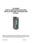
1
PWR-16 16-CHANNEL MULTIZONE AUDIO POWER AMPLIFIER User Manual miniDSP Ltd, Hong Kong / www.minidsp.com / Features and specifications subject to change without prior notice 1 Revision history Revision 0.1 0.2 1.0 1.1 1.2 Description First draft Second draft First release version Updates for control switches Corrected Phoenix connections Date 22 June 2015 20 July 2015 6 October 2015 7 October 2015 7 October 2015 miniDSP Ltd, Hong Kong / www.minidsp.com / Features and specifications subject to change without prior notice 2 TABLE OF CONTENTS Important Information......................................................................................................................................... 4 Disclaimer/Warning ......................................................................................................................................... 4 Warranty Terms ............................................................................................................................................... 4 FCC Class B Statement...................................................................................................................................... 4 Safety & EMC standards ................................................................................................................................... 5 A Note on this Manual ..................................................................................................................................... 5 Safety Instructions ............................................................................................................................................... 6 1 Product Overview .......................................................................................................................................... 9 1.1 Key Features and Benefits .................................................................................................................... 9 1.2 Maximum power capabilities................................................................................................................ 9 1.3 Typical applications ............................................................................................................................ 10 1.3.1 Home theater ............................................................................................................................. 10 1.3.2 Multizone audio.......................................................................................................................... 10 2 Installation and connectivity ........................................................................................................................ 11 2.1 Power................................................................................................................................................. 11 2.2 Signal ................................................................................................................................................. 11 2.2.1 Inputs ......................................................................................................................................... 11 2.2.2 Outputs ...................................................................................................................................... 11 2.2.3 Single-ended mode ..................................................................................................................... 12 2.2.4 BTL mode ................................................................................................................................... 12 3 Status and control ....................................................................................................................................... 13 3.1 Status LEDs ......................................................................................................................................... 13 3.2 Control I/O ......................................................................................................................................... 14 3.2.1 Zone enable/disable ................................................................................................................... 14 3.2.2 Control I/O connector ................................................................................................................. 14 3.2.3 Turning on the PWR-16 ............................................................................................................... 15 3.2.4 Status outputs ............................................................................................................................ 17 3.2.5 Delayed 12V output trigger ......................................................................................................... 17 4 Additional information ................................................................................................................................ 18 4.1 Specifications ..................................................................................................................................... 18 4.2 Obtaining support .............................................................................................................................. 18 miniDSP Ltd, Hong Kong / www.minidsp.com / Features and specifications subject to change without prior notice 3 IMPORTANT INFORMATION Please read the following information before use. In case of any questions, please contact miniDSP via the support portal at minidsp.desk.com. DISCLAIMER/WARNING miniDSP cannot be held responsible for any damage that may result from the improper use or incorrect configuration of this product. Please read this manual carefully to ensure that you fully understand how to operate and use this product, as incorrect use or use beyond the parameters and ways recommended in this manual have the potential to cause damage to your audio system. Please also note that many of the questions we receive at the technical support department are already answered in this User Manual and in the online application notes on the miniDSP.com website. So please take the time to carefully read this user manual and the online technical documentation. Thank you for your understanding! WARRANTY TERMS miniDSP Ltd warrants this product to be free from defects in materials and workmanship for a period of one year from the invoice date. Our warranty does not cover failure of the product due to incorrect connection or installation, improper or undocumented use, unauthorized servicing, modification or alteration of the unit in any way, or any usage outside of that recommended in this manual. If in doubt, contact miniDSP prior to use. FCC CLASS B STATEMENT This device complies with Part 15 of the FCC Rules. Operation is subject to the following two conditions: This device may not cause harmful interference. This device must accept any interference received, including interference that may cause undesired operation. Warning: This equipment has been tested and found to comply with the limits for a Class B digital device, pursuant to Part 15 of the FCC Rules. These limits are designed to provide reasonable protection. This equipment generates, uses and can radiate radio frequency energy and, if not installed and used in accordance with the instructions, may cause interference to radio communications. However, there is no guarantee that interference will not occur in a particular installation. If this equipment does cause harmful interference to radio or television reception, which can be determined by turning the equipment off and on, the user is encouraged to try to correct the interference by one or more of the following measures: Reorient or relocate the receiving antenna. Increase the separation between the equipment and receiver. Connect the equipment into an outlet on a circuit different from that to which the receiver is connected. Consult the dealer or an experienced radio/TV technician for help. Notice: Shielded interface cable must be used in order to comply with emission limits. miniDSP Ltd, Hong Kong / www.minidsp.com / Features and specifications subject to change without prior notice 4 Notice: Changes or modification not expressly approved by the party responsible for compliance could void the user’s authority to operate the equipment. SAFETY & EMC STANDARDS Safety & EMC standards covered: UL 60065, 7th edition, 2013-07-24 CAN/CSA-C22.2 No. 60065-03, 1st Edition + A1: 2006 + A2: 2012 IEC 60065:2001 (Seventh Edition) + A1: 2005 + A2: 2010 EN 60065:2002 / A1: 2006 / A11: 2008 / A2: 2010 / A12: 2011 EMC standards covered are: EN 55013: 2001 + A1: 2003 + A2: 2006 CISPR 13: 2001 + A1: 2003 + A2: 2006 EN 61000-3-2: 2006 + A1:2009 + A2: 2009 IEC 61000-3-2: 2005 + A1:2009 + A2: 2009 EN 61000-3-3: 2013 IEC 61000-3-3: 2013 EN 55020: 2007 + A11: 2011 CISPR 20: 2006 IEC 61000-4-2: 2008 IEC 61000-4-4: 2012 FCC 47 CFR Part 15 Subpart B ICES-003 Issue 5-2012 ANSI C63.4-2009 A NOTE ON THIS MANUAL This User Manual is designed for reading in both print and on the computer. If printing the manual, please print double-sided. The embedded page size is 8 ½” x 11”. Printing on A4 paper will result in a slightly reduced size. For reading on the computer, we have included hyperlinked cross-references throughout the manual. In addition, a table of contents is embedded in the PDF file. Displaying this table of contents will make navigation much easier: In Adobe Reader on Windows, click on the “bookmarks” icon at the left. The table of contents will appear on the left and can be unfolded at each level by clicking on the “+” icons. In Preview on the Mac, click on the View menu and select Table of Contents. The table of contents will appear on the left and can be unfolded at each level by clicking on the triangle icons. miniDSP Ltd, Hong Kong / www.minidsp.com / Features and specifications subject to change without prior notice 5 SAFETY INSTRUCTIONS Read all information for installation, connection, and usage. Keep this user manual in a safe place during the lifetime of the product. The user manual forms an integral part of the product. Reselling of the product is only possible if the user manual is available. Any changes made to the product have to be documented in writing and passed on to the buyer in the event of resale. Heed all warnings. Follow all instructions. Do not use this product near water (for example, in damp rooms or near a swimming pool). Clean only with a dry cloth. Do not cover the heat sink. Install in accordance with the user manual. Do not install near any heat sources such as radiators, heat registers, stoves, or other apparatus that produce heat. Protect the power cord from being walked on, pinched or damaged in any way. Pay particular attention to plugs and the point where they exit from the Amplifier Unit. The product may only be used in accordance with the information provided in the user manual. Before and during the usage of the amplifier please ensure that all recommendations, especially the safety recommendations as detailed in the user manual, are adhered to. The Amplifier Unit is designed for the amplification of pulsed audio signals and the Amplifier Unit should only be connected to speakers with average impedance that is not lower than the impedances specified in the User's Manual. Do not place the product on an unstable cart, stand, tripod, bracket, or table. The device may fall, causing serious injury, and serious damage to the device itself. The Amplifier Unit can only be disconnected from the power supply by removing the plug, which must be freely accessible at all times. Unplug this Amplifier Unit during lightning storms or when unused for long periods of time. Refer all servicing to qualified service personnel. Damage that requires service Unplug the Amplifier Unit from the mains supply and refer to your dealer/distributor or other authorized repair workshop. Servicing is required when: 1. The power-supply cord or plug has been damaged, 2. Liquid has been spilled or objects have fallen into the amplifier, 3. The amplifier has been exposed to rain or moisture, 4. The amplifier has been dropped or suffered damage in any way, 5. The amplifier exhibits a distinct change from its normal function or performance. miniDSP Ltd, Hong Kong / www.minidsp.com / Features and specifications subject to change without prior notice 6 Servicing Do not attempt to service this product yourself. As opening or removing covers may expose you to dangerous voltage or other hazards, the amplifier may only be opened by qualified personnel. Please refer to your dealer/distributor. Servicing and Replacement Parts All service and repair work must be carried out by an authorized dealer/distributor. When replacement parts are required, please ensure that the dealer/distributor only uses replacement parts specified by the manufacturer. The use of unauthorized replacement parts may result in injury and/or damage through fire or electric shock or other electricity-related hazards. Safety Check Upon completion of any service or repairs to this product, ask the dealer/distributor to perform safety checks to determine that the amplifier is in proper operating condition. Read the information for use (user manual) When shipping the product, always use the original shipping carton and packing materials. For maximum protection, repack the unit as it was originally packed at the factory. Environments Use this product only in E1, E2, E3 or E4 environments according to EN55103-2 “Electromagnetic compatibility – Product family standard for audio, video and audio-visual and entertainment lighting control apparatus for professional use – Part 2: Immunity” Ventilation and heat sink The heat sink and ventliation slots are provided to ensure reliable operation of the Amplifier Unit and to protect it from overheating. The heat sink and ventilation slots must not be blocked or covered. This product should not be installed unless proper ventilation is provided and manufacturer’s instructions have been adhered to. Water And Moisture Do not use this product near water (for example, in damp rooms or near a swimming pool). Cleaning Unplug the Amplifier Unit from the wall outlet before cleaning. Do not use liquid or aerosol cleaners. Power-cord Protection Power supply cords should be routed so that they are not likely to be walked on or pinched by items placed upon them or against them, paying particular attention to cords and plugs, and the point where they exit from the Amplifier Unit. Lightning For added protection of the product during lightning storms, or when it is left unattended and unused for long periods of time, unplug it from the wall outlet. This will prevent damage to the product due to lightning and power-line surges. Disconnection from the mains power supply can only be achieved by removing the plug from the mains socket and by external disconnection of all poles from the mains. miniDSP Ltd, Hong Kong / www.minidsp.com / Features and specifications subject to change without prior notice 7 Interference of external objects and/or liquids with the appliance Never push objects of any kind into this product through openings as they may touch dangerous voltage points or short out parts that could result in a fire or electric shock. Never spill liquid of any kind on the amplifier. Accessories Do not place this product on an unstable cart, stand, tripod, bracket, or table. The product may fall, causing serious injury, and serious damage to the product. Any mounting of the product should follow the manufacturer’s instructions, and should use a mounting accessory recommended by the manufacturer. Connecting When you connect the Amplifier Unit to other equipment, turn off the power and unplug all of the equipment from the supply source. Failure to do so may cause an electric shock and serious personal injury. Read the user's manual of the other equipment carefully and follow the instructions when making the connections. Sound Volume Reduce the volume to minimum before you turn on the amplifier to prevent sudden high levels of noise which may cause hearing or speaker damage. Output connectors WARNING: Output connectors marked with the lightning flashes indicate high voltages that are potentially life threatening. Wiring to these terminals requires installation by an instructed person and the use of ready-made leads or cords. Custom wiring should only be carried out by qualified personnel. To prevent electric shock, do not operate the product with any of the conductor portion of the speaker wire exposed. NOTE: For reasons of safety and performance, use only high-quality fully insulated speaker cables of stranded copper wire. Use the largest wire size that is economically and physically practical, and make sure the cables are no longer than necessary. Precautions when connecting to MAINS IN When mounting or connecting the product always disconnect it from mains. Only connect the product to an appropriate AC circuit and outlet, according to the requirements indicated on the rating plate. If a power cut occurs while the amplifier is switched on, it will restart automatically once the power supply has been restored. All settings prior to the loss of power will be maintained. IMPORTANT: Always connect the Product to mains through the MAINS IN connector on the Amplifier Unit. IMPORTANT: Always use ready-made mains cables with original connectors when connecting the product to mains. IMPORTANT: When disconnecting the Product from the mains, always disconnect at the mains end first, before disconnecting the connector at the Product end. DO NOT REMOVE MAINS CONNECTOR GROUND, IT IS ILLEGAL AND DANGEROUS. miniDSP Ltd, Hong Kong / www.minidsp.com / Features and specifications subject to change without prior notice 8 1 PRODUCT OVERVIEW The miniDSP PWR-16 is a 400 Watt ultra-compact, highly-efficient audio power amplifier intended for multizone custom installations in modern homes, hotels, restaurants, bars, theatres, auditoriums, amusement parks, shopping malls etc. This amplifier is one of the lightest and most compact of its kind and excels with its impressive power-to-size ratio and its incredible power efficiency. The PWR-16 features 16 channels of amplification by ICEpower® in eight zones. Each amplification channel can deliver peak power of 80W into a 4 ohm speaker. The two channels in a zone can be switched to BTL (bridge-tied load) mode to deliver peak power of 160W into an 8 ohm speaker. The result is an extremely flexible amplifier that can be used in many configurations. A comprehensive set of control and protection features make the amplifier extremely flexible and robust. Remote enable, signal detection, and individual disabling of zones ensure minimum power consumption. 1.1 KEY FEATURES AND BENEFITS • Ultra-compact 1U rack enclosure • Extremely low weight • 400 Watts of audiophile sound quality in eight separate zones for exceptional installation convenience • Amplification by ICEpower® • Low power consumption and heat dissipation • Comprehensive protection keeps the music playing and your quality costs down • Removable rack ears and feet • High construction quality for professional use 1.2 MAXIMUM POWER CAPABILITIES The PWR-16 is designed for use in applications where individual amplification channels are capable of output power well in excess of the total power divided by the number of channels. This includes applications such as multizone applications (where not all zones are typically being used simultaneously) and immersive audio applications (where only a subset of speakers are playing substantial output at one time). For example, the PWR-16 has a total output power capability of 400 Watts. Dividing this by 16 results in 25 Watts per channel. However, each channel of the PWR-16 is capable of 80 Watts of power output. The PWR-16 can be used in applications other than those mentioned above. However, it is important to keep in mind and to not exceed the total power output of the amplifier. For example, in an multichannel active system, some drivers (tweeter and midrange) will use substantially less power than the woofers. miniDSP Ltd, Hong Kong / www.minidsp.com / Features and specifications subject to change without prior notice 9 1.3 TYPICAL APPLICATIONS 1.3.1 Home theater The figure below shows a typical home theater application. In this system, the DDRC-88A is used to perform Dirac Live® room correction and the PWR-16 is used for amplification. In the scenario shown, each speaker can be driven by one channel (4 ohm load, single-ended mode) or by a zone in BTL mode (minimum load 6 ohms). Please observe the maximum power capability across all channels. 1.3.2 Multizone audio The figure below shows a multi-zone audio connection, as described in our app note Multi-zone DRC with the DDRC-88A Dirac Live® processor. In the case where more than one speaker is driven from each input channel, use "Y"-splitters on the PWR-16 inputs to utilize more channels. miniDSP Ltd, Hong Kong / www.minidsp.com / Features and specifications subject to change without prior notice 10 2 INSTALLATION AND CONNECTIVITY The PWR-16 amplifier should be mounted in an audio/video rack or on a solid flat surface. Be sure to keep a minimum of 2 inches of clearance on each side of the case, to ensure proper air ventilation for the two fans mounted in the side panels. The case also includes removable rack ears and removable feet for proper mounting. 2.1 POWER The PWR-16 accepts any voltage from 85 to 264 VAC, at cycle rates from 45 to 65 Hz. AC power is connected via a IEC 320 C13 power connector on the rear panel. Power is turned on and off with the AC mains switch on the rear panel. 2.2 SIGNAL The PWR-16 has 16 amplification channels, grouped into eight zones. By convention, each zone is spoken of as a stereo pair (left and right channels), but in actual usage, the channels can be used in any manner suited to the application. Each zone can be used as two independent channels, or switched into BTL mode, which delivers twice the power into a single loudspeaker. The setting for each zone is independent, allowing a large number of different configurations. 2.2.1 Inputs Inputs are connected directly to the relevant RCA jack on the rear panel. Caution: Please be sure to turn the amplifier off before you make changes to the input connections. 2.2.2 Outputs Speaker outputs are provided via a set of eight removable 4-way Phoenix terminal blocks. Each terminal block connects one zone. These terminal blocks accept bare wire terminations. To make connections, remove a terminal block or blocks from the rear of the amplifier. Connect individual wires from the speaker cables to each set of screw terminals as shown below. After all connections to the terminal block are secure, firmly re-insert the terminal blocks. Caution: Please be sure to turn the amplifier off before you make changes to the loudspeaker connections. miniDSP Ltd, Hong Kong / www.minidsp.com / Features and specifications subject to change without prior notice 11 2.2.3 Single-ended mode In single-ended mode, both channels of the zone are independent, and can drive up to 80 Watts peak power into a nominal 4 ohm (minimum) loudspeaker. The mode switch must be set to the "SE" position, as illustrated in the following diagram. 2.2.4 BTL mode In BTL (bridge-tied load) mode, both channels in a zone are used to drive one loudspeaker. Combined, the two channels in a zone can deliver up to 160 Watts peak power into a nominal loudspeaker load of 6 to 8 ohms1. The mode switch must be set to the "BTL" position, as illustrated in the following diagram. The input signal is connected to the odd-numbered input only. The output signal to the loudspeaker is taken from the "hot" outputs of both amplification channels, as illustrated. 1 The PWR-16 is stable into a 4 ohm load when in BTL mode. However, an impedance this low places additional thermal stress on the amplifier (in other words, it will heat up more quickly). We therefore recommend that a minimum 6 ohm load be used for zones in BTL mode. miniDSP Ltd, Hong Kong / www.minidsp.com / Features and specifications subject to change without prior notice 12 3 STATUS AND CONTROL 3.1 STATUS LEDS Power LED The POWER LED indicates that the AC mains power is connected to the amplifier and that the power switch is turned on. This LED is red if the amplifier is in standby mode and green when it is powered on. Over-current/clipping LED The CLIP LED indicates an overload state in the amplifier. If this LED lights yellow, it indicates that the amplifier has shut down because of excessive current draw on one or more outputs. This can occur in the event of a short-circuit on the outputs or excessive current draw from the speaker load. If this LED lights red, it indicates that the power supply has either exceeded its thermal limits, or there has been excessive current draw from the power supply. The power supply will limit its output power to safe limits, but the amplifier will not shut down. Thermal protection LED The PROTECT LED indicates that one or more zones has gone into thermal protection mode. The temperature of each zone is continuously monitored. If a zone reaches its thermal limit (105 ̊C) then that zone will shut down and go into soft start mode. The thermal protection LED will turn red at this time. Other zones that are within thermal limits will continue to be active. When the temperature has dropped below the thermal threshold, the respective zone(s) will resume normal operation. miniDSP Ltd, Hong Kong / www.minidsp.com / Features and specifications subject to change without prior notice 13 3.2 CONTROL I/O The rear panel contains a set of control switches and I/O terminals: 3.2.1 Zone enable/disable Each zone can be disabled by moving the corresponding DIP switch to the "down" position. It is recommended that zones that are not in use are disabled to reduce power consumption and heat dissipation. 3.2.2 Control I/O connector The 10-pin Phoenix connector on the rear panel carries a comprehensive set of control signal inputs and outputs. The pinout is shown in Table 1. Pin 1 2 3 4 5 6 7 8 9 10 Type Input Ground Input Output Ground Input Output Output Output Ground Name Signal Sense IN Signal Sense Ground 12V Trigger IN 12V Trigger OUT Logic/Trigger Ground 3−5V Trigger IN Thermal Overload Overcurrent Monitor Amplifier On Status Ground Table 1. Control I/O pins miniDSP Ltd, Hong Kong / www.minidsp.com / Features and specifications subject to change without prior notice 14 3.2.3 3.2.3.1 Turning on the PWR-16 Power on/off switch The power switch on the rear panel turns power to the complete amplifier on and off. For this switch to always put the amplifier into normal operation mode: Set the 3−5V Trigger switch to High. Set the External Signal Sense switch to Off. Leave Pin 3, 12V Trigger IN disconnected. Leave Pin 6, 3−5V Trigger IN disconnected. 3.2.3.2 Signal Sense The PWR-16 can be turned on by sensing an audio signal. The signal sense input is connected to Pin 1, with Pin 2 used as ground reference. Typically, a "Y" connection is made from one of the amplifier input channels, as shown in the diagram below. To use signal sense switching: Set the 3−5V Trigger switch to Off. Set the External Signal Sense switch to On. Leave Pin 3, 12V Trigger IN disconnected. Leave Pin 6, 3−5V Trigger IN disconnected. Connect the sense signal to Pin 1, Signal Sense IN with Pin 2, Signal Sense Ground as ground reference. miniDSP Ltd, Hong Kong / www.minidsp.com / Features and specifications subject to change without prior notice 15 3.2.3.3 12V Trigger The PWR-16 can be turned on with an external 12V trigger signal. This is applied to Pin 3, with Pin 5 used as ground reference. The amplifier will be turned on when the trigger signal is at 12V and off when it is at 0 V. Pin 4 is hard-wired to Pin 3, and is intended for use as a 12V trigger output. To use an external 12V trigger: Set the 3−5V Trigger switch to Off. Set the External Signal Sense switch to Off. Leave Pin 6, 3−5V Trigger IN disconnected. Connect the trigger signal to Pin 3, 12V Trigger IN, using Pin 5, Logic/Trigger ground as ground reference. miniDSP Ltd, Hong Kong / www.minidsp.com / Features and specifications subject to change without prior notice 16 3.2.3.4 3−5V Trigger The PWR-16 can be turned on with an external logic-level trigger signal, of 3 to 5 V. This is applied to Pin 6, with Pin 5 used as ground reference. The amplifier will be turned on when the trigger signal is high at 3 to 5 V and off when it is at 0 V. To use an external logic-level trigger: Set the 3−5V Trigger switch to Off. Set the External Signal Sense switch to Off. Leave Pin 3, 12V Trigger IN disconnected. Connect the logic-level trigger signal to Pin 6, 3−5V Trigger IN, using Pin 5, Logic/Trigger ground as ground reference. 3.2.4 Status outputs Pins 7 and 8 provide logic-level status output of thermal overload and overcurrent detected. These outputs reflect the status of the front panel LEDs. 3.2.5 Delayed 12V output trigger The PWR-16 amplifier has a 12 V output trigger signal which can turn be used to turn on other amplifiers or electronics. Pin 9, Amplifer On goes high about a second after the amplifier is turned on, and returns low when the amplifier goes into standby mode. Note that this pin is not the same as Pin 4. Pin 4 is the same as the input on Pin 3, whereas Pin 9 reflects the amplifier's state regardless of how it is turned on. For example, it can be used to set one PWR-16 as the master unit for multiple units. miniDSP Ltd, Hong Kong / www.minidsp.com / Features and specifications subject to change without prior notice 17 4 ADDITIONAL INFORMATION 4.1 SPECIFICATIONS Channel count 16 single-ended channels, or 8 BTL channels, or any combination of SE and BTL Total power output 400 Watts (Up to 80 seconds) Total continuous power output 80 Watts Per-channel peak power output, SE mode Up to five channels driven: 80W per channel All 16 channels driven: 25W per channel (4 ohms, SE, continuous long-term power output across all channels without thermal shutdown, Ta = 25 OC) (4 ohms, 0.1% THD+N, 20Hz < f < 20kHz, up to 80 seconds) Per-channel peak power output, BTL mode Two zones driven: 160W per zone All zones driven: 50W per zone (8 ohms, 0.1% THD+N, 20Hz < f < 20kHz, up to 80 seconds) THD + N 0.003%, 4Ω, SE, f=100Hz, Po=1W Dynamic range 110dBA SE, 115dBA BTL Frequency response ±0.4 dB, 10Hz- 20kHz, all loads Input sensitivity 0.92 VRMS (for 80W output in SE mode, 160W output in BTL mode) Input impedance 47 kΩ Certification FCC / CE / IEC / PSE / C-TICK AC mains supply 85-264 V AC, 45-65 Hz Fuse rating 6.3A Dimensions (H x W x D) 44 x 424 x 314 mm (1RU height, width 482 mm with rack ears) Weight 7.7 lbs/3.5 kg 4.2 OBTAINING SUPPORT 1. Check the forums on miniDSP.com to see if this issue has already been raised and a solution or solutions provided. 2. Contact miniDSP via the support portal at minidsp.desk.com with: a. The product information. b. A clear explanation of the symptoms you are seeing. c. A description of the troubleshooting steps you performed and the results obtained. miniDSP Ltd, Hong Kong / www.minidsp.com / Features and specifications subject to change without prior notice 18