1
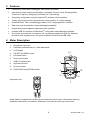
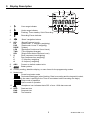
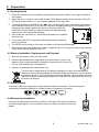
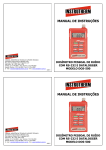
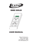
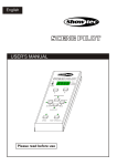
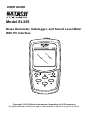
USER GUIDE Model SL355 Noise Dosimeter, Datalogger, and Sound Level Meter With PC Interface Copyright © 2012 Extech Instruments Corporation (a FLIR company) All rights reserved including the right of reproduction in whole or in part in any form. 1. Table of Contents 1. Table of Contents ……………………………………………………………….…….. 2 2. Introduction …………………………………………….………………………….…… 3 3. Features …………………………………………………………………………….….. 4 4. Meter Description ……………………………………………………………………... 4 5. Display Description ……………………………………………………………….…… 5 6. Preparation ………………………………………………………………………….…. 6 6.1 Getting Started ……….……………………………………………..……............ 6 6.2 Battery Installation, Replacement, and Disposal ……………………………… 6 6.3 Batter Status Symbols …………………………………………………........…… 6 6.4 Microphone Installation …………………………………………..……….……… 6 7. Calibration Procedure ……………………………………………………….………... 7 8. Dose Testing and Datalogging …………………………………………….………… 8 8.1 Overview of Dose Testing and Datalogging ……………………..………...….. 8 8.2 Running Dose Tests and Datalogger ……………………………………..……. 8 8.3 Reviewing Dose Test Setups and Measurement results ………….........…… 9 8.4 Review Stored Datalogger Data ……………………………………..........……. 9 8.5 Data Mode - Menu Table ………………………….………………………..…… 10 8.6 Data Mode - Meter Screen Shots ………………………………………..…….. 11 8.6.1 Select Dose Meter Setup from Memory ……………..………….………. 9. 10. 11. 11 8.6.2 Measure and Store Dose Data ……………………...………….………… 11 8.6.3 Screen Shots for Recalling and Reviewing Dose Data …..…….……… 14 Sound Level Meter (SLM) Mode ……………………………………………….……. 15 9.1 SLM Menu Table ……………………...……………………………………..….... 15 9.2 SLM Screen Shots ……………………..………………………………..……..… 16 Meter Setup - Software Method ……………..………………………...…….………. 18 Meter Setup - Manually ………………………..……………………………………… 18 11.1 SETUP Mode ……………………………….…………………...……....………. 18 11.2 SETUP Mode - Menu Table …………………………..………………….…….. 18 11.3 SETUP Mode - Screen Shots ……………………...……………………...…… 19 11.4 OPTION Mode ……….…..……………………………………………..……….. 21 11.5 OPTION Mode - Menu Table ……………………………….……...….………. 21 11.6 OPTION Mode - Basic Screen Shots …………………..………….………….. 23 11.7 OPTION Mode - Set the Time and Date ………...……..…...………….…….. 24 11.8 OPTION Mode - Editing ……………...………………………………….……… 25 12. Clear the Meter’s Memory ……………………………………………….…………… 27 13. Specifications ………………………………………………………….………………. 28 14. Maintenance …………………………………………………………………….……... 31 15. Software Installation and Operation …………………………………….…………... 31 16. Glossary of Terms ……………………………………………………….……………. 32 2 SL355-EU-EN-V1.4 2. Introduction Congratulations on the purchase of the Model SL355. The SL355 is a combination Noise Dosimeter, Datalogger, and Sound Level Meter (SLM). The SL355 can be configured manually via push-button navigation of the menu system or through the PC interface using the supplied software (recommended for ease of use). Refer to the dedicated software User Guide on the supplied CDROM for detailed instructions on using the software program for downloading data, configuring the SL355 meter, and remotely controlling the meter. The SL355 Noise Dosimeter is designed to test noise exposure and provide noise surveys for compliance with OSHA, MSHA, DOD, ACGIH, and ISO standards. The SL355 monitors accumulated noise exposure and measures frequency weighted noise exposure and peak sound 2 level simultaneously for % dose and TWA (time weighted average or sound exposure in Pa h). Up to twenty (20) noise surveys can be recorded and up to five (5) automated dose tests can be programmed up to 30 days in advance. Each test includes a ‘repeat’ feature where tests can be rerun a pre-programmed number of times. Criterion Level, Threshold, Exchange rate and other parameters are user-programmable. Noise Survey results can be viewed on the meter’s display and downloaded using the supplied PC software. The SL355 Sound Level Meter (SLM) displays real-time sound pressure level (SPL) readings along with LEQ, SEL, and elapsed time as a typical type 2 SLM would. The SLM has selectable measurement ranges: 60 to 130 & 70 to 140dB, ‘A’ and ‘C’ frequency weightings, Linear ‘Z’, and ‘C’ Peak weightings, Fast & Slow response time settings, and an adjustable energy exchange rate (Q). The SL355 Datalogger has a built-in real-time clock for date/time stamped data records. The datalogger can store up to 14,400 readings in the meter’s memory. Sampling time (rate) is programmable from 1 second per reading up to 1 hour per reading. Logged readings are downloaded using the supplied PC software. This device has been calibrated and tested before shipment. With proper care, years of reliable service can be expected. Conventions of this User Guide The SL355 is a sophisticated device with a variety of features. This User Guide is intended to optimize the user experience with regard to ease of use and convenience. To accomplish this, most sections of this User Guide include instructional text, a Menu table, and a section that illustrates the actual “Screen shots” seen by the user while programming the meter. Be sure to review all three of these approaches (instructional text, menu tables, and screen shots) and determine if one, or a combination of the three, work best for the application at hand. If questions arise please contact our technical support staff. 3 SL355-EU-EN-V1.4 3. Features Combination Dose Meter, Datalogger, and Sound Level Meter. User-defined measurement configurations. Selectable Criterion Level, Exchange Rate, Threshold, Frequency Weighting, and Response Time settings. Completely configurable using the supplied PC software (recommended). Twenty (20) internal memory locations with a total capacity of 14,400 readings. Download Dose, TWA, and Datalogger data to a PC using supplied PC software. Real-time clock and date/time stamp datalogging capability. Keypad lock protects against inadvertent meter operation. Included USB PC interface and Windows Kit includes a microphone, microphone clip, microphone windscreen, belt clip, batteries, protective case, keypad cover, user guide, software CD-ROM, and USB cable. TM configuration and datalogging software. 4. Meter Description 1. Microphone input jack 2. Calibration potentiometer for 114db adjustment 3. LCD Display 4. ON-OFF and MENU button 5. Left arrow button 6. Down arrow button 7. USB PC interface jack 8. Right arrow button 9. Up arrow button 21 3 10. RUN/PAUSE and RETURN button 4 6 9 5 10 8 Keyboard cover: 7 Notes: Battery compartment and belt clip are located on rear of meter. Microphone lapel clip, calibration screwdriver, microphone, windscreen, and other kit items are not pictured. 4 SL355-EU-EN-V1.4 5. Display Description 6 7 12 13 8 10 1. Over range indicator 2. 3. 9 1 2 Under range indicator REC 4. Flashing: Timer standby; Solid: Recording 3 4 11 5 Recording Pause indicator ‘Smart’ navigation buttons 5. 6. SPL PK PKZ DOSE LEQ TWA SEL (Sound Pressure Level) (Peak mode: ‘C’ frequency weighting) (Peak mode: Linear ‘Z’ weighting) (%dose) (Equivalent Continuous Sound Level) (Time Weighted Average) (Single Event Noise Exposure Level) 7. S F C A Slow (response time weighting) Fast (response time weighting) ‘C’ frequency weighting ‘A’ frequency weighting 8. dB% Percent or decibel readout units 9. Battery status 10. Primary reading, date/time display, or menu items for the programming modes 11. Mode Icons: SLM Sound level meter mode DATA Dosimeter/Datalogger (when flashing, Data is recording and the keypad is locked; when solid, the meter is waiting for the Timer to countdown before recording can begin) SET UP Setup mode of operation OPTION Option mode of operation 12. Headphone icon indicates that a SPL of over 115db has occurred 13. BEG END DUR Start test time Stop test time Test duration 5 SL355-EU-EN-V1.4 6. Preparation 6.1 Getting Started 1. Power the instrument by momentarily pressing the power/menu button at the upper left side of the keypad. 2. When the unit is turned on, the model number (355) appears briefly on the left side of the LCD and the firmware version (1.1, for example) appears on the right side. 3. The meter defaults to the SLM mode (SLM icon is shown) where the main display indicates the sound pressure level (SPL) in db, the A/C frequency weighting setting, the F/S response time setting, and the battery status icon (an up or down arrow will be visible if the current reading is above or below the selected range respectively). See screen shot diagram. 4. If the meter will not switch on, check that the batteries are installed and are fresh. 5. To turn the meter OFF, press and hold the power/menu button for three (3) seconds. 6. The SL355 can be used as a Sound Level Meter or a Dosimeter/Datalogger. 7. Note that the four arrow buttons are ‘smart’ navigation keys. For any given meter mode only the active arrow buttons appear on the LCD. 6.2 Battery Installation, Replacement, and Disposal 1. Slide the rear battery cover off of the meter. 2. Remove the old batteries (if applicable) and insert three (3) ‘AAA’ 1.5V batteries. Ensure that the battery orientation and polarity are correct. Do not mix fresh and partially used batteries. 3. Carefully re-assemble the meter before use. The end user is legally bound (EU Battery ordinance) to return all used batteries, disposal in the household garbage is prohibited! Bring used batteries / accumulators to collection points in your community or wherever batteries / accumulators are sold! Disposal: Follow the valid legal stipulations in respect of the disposal of the device at the end of its lifecycle 6.3 Battery Status The battery status icon appears as empty when the battery is depleted. The battery symbol indicates the remaining capacity in numbers of bars or segments, as follows: >84% >65% >25% >11% 0% 6.4 Microphone installation Insert the microphone plug into the connector on the top of the meter as shown in accompanying diagram. Turn clockwise to secure in place; be careful not to overtighten. 6 SL355-EU-EN-V1.4 7. Calibration Procedure 1. A standard 114db acoustic calibrator is required (as shown in diagram below). 2. Insert the meter’s microphone carefully into the insertion hole of the calibrator (as shown). 3. Switch the calibrator ON and set its output amplitude to 114 db. 4. Switch the meter ON. 5. Access the Calibration mode (CL) by repeatedly pressing the MENU button until the CL XX.X display is shown and the SLM, DATA, SETUP, and OPTION mode icons are all switched off (refer to accompanying screen shot illustration). 6. Adjust the meter’s potentiometer (recessed at top of meter) using the supplied adjustment tool until the display reads 114db, matching the 114db output level of the calibrator. 7. Press the RUN/PAUSE/RETURN button to save the calibration. 7 SL355-EU-EN-V1.4 8. Dose Testing and Datalogging 8.1 Overview The dosimeter noise survey and datalogging functions operate at the same time. For example, while the %dose and TWA (time weighted average) values are being calculated and displayed (for the dose meter’s noise survey) individual SPL readings are being stored by the datalogger. Noise surveys and logged data are stored in ‘RUNS’ which are memory locations (1 to 20). Note that the meter can collect up to 14,400 readings total, spread out over the 20 RUN memory locations. The ‘RUN’ parameter is located in the DATA menu. The DATA Mode Menu table and a Screen-Shot section are provided directly after the instructional text below: 8.2 Running the Dose Meter Noise Survey and Datalogger 1. Use the supplied software program (recommended) to configure the meter’s noise survey and datalogging parameters (a software User Guide is provided on the supplied CD-ROM), or manually configure the meter following the instructions provided in the SETUP and OPTION mode sections of this guide. For compliance, the noise survey parameters must match the requirements of the regulation/standard in question. 2. In the SETUP mode (or using the supplied software) set the Criterion Level, Exchange Rate, Threshold, Frequency Weighting, Response time, Range, and Peak parameters. Note that if a configuration has already been stored, it can be recalled in the SETUP mode. Reference Section 11.3 for SETUP Mode details. 3. In the OPTION mode (or using supplied software) set the Date/Time, Test Duration, Test Begin (BEG) time, Test End time, Sample rate (logging period), Repeat, Pair, and Timer functions. Reference Section 11.5 for OPTION Mode details. 4. For the entirety of the test, the microphone should be clipped to the test person’s lapel and the meter should be clipped to the test person’s belt. 5. To run the dosimeter/datalogger the meter must be in the DATA Mode of operation. Press the Menu button to select the DATA Mode (if not already selected). TIMER Notes: The Timer setting is critical for determining whether the test begins immediately (Timer OFF) or at a programmed time (Timer ON). With the TIMER set to OFF, recording can begin immediately by pressing the RUN/PAUSE button. When the meter is recording, the REC icon will appear solid and the DATA icon will flash. With the TIMER set to ON, and with the Beginning and End times programmed, after RUN/PAUSE is pressed recording will NOT start until the programmed Begin (BEG) time is reached. The REC icon will be flashing (indicating that the meter is in “standby” waiting for the Begin time); the DATA icon will be on solid. Up to 5 Begin/End times can be pre-set and tests can be programmed up to 30 days in advance. 8 SL355-EU-EN-V1.4 DUR (DURATION) Notes: DUR allows the user to select a specific RUN Duration time. When a duration period is set by the user to anything other than OFF, it takes precedence over the Timer setting so that any preset Begin and End times will be ignored. DUR is available in the OPTION mode menu. 6. While testing, the meter’s DATA menu can be navigated (see DATA Menu table and Screen Shots below) as long as the keypad is unlocked. This allows the user to view the current setup, % dose, and TWA while the test is running. 7. The arrow keys are locked automatically when recording begins. Press ◄ and ▼ simultaneously to unlock the keypad. The DATA icon will cease flashing, indicating that the keypad is unlocked and ready for navigation. To re-lock the keypad, press ▲and ► simultaneously. 8. To pause a recording, press RUN/PAUSE. The pause icon || will appear. Press again to resume. 9. To stop the recording if the END time has not been automatically set, first unlock the keypad by pressing ◄ and ▼ simultaneously and then press the MENU key. The display will show STOP and will count down from 3 to zero; press the RUN/PAUSE button before zero is reached to successfully stop the recording. 10. Switch the meter off to conserve battery power. To switch the meter off, press and hold the menu button until the unit switches off. 11. %Dose and TWA calculations are viewable using the PC interface or by navigating the DATA mode (refer to the DATA Menu table and Screen Shots below). Individually logged readings are retrievable via the PC interface only. Follow the directions in the Software User Guide supplied on the enclosed CD-ROM. Testing notes: Do not shout into the microphone or strike the microphone as this will affect the test. To obtain reliable data, the user’s activities must reflect a typical workday. 8.3 Reviewing Noise Survey Setups and Measurement Results 1. Note that the PC interface can be used to review setups and measurement results. Refer to the Software User Guide on the supplied CD-ROM for instructions. To work manually, follow the steps below. 2. Switch the meter ON; the meter will be in the SLM mode. Press MENU to access the DATA mode. 3. Use ► to scroll to the ‘RUN’ display. Now use▼▲ to select the desired RUN (memory location). 4. When the desired RUN is selected, use ◄ ► to scroll the setup data and noise survey results as shown in the DATA Menu table and Screen Shots below. 8.4 Reviewing Stored Datalogger Data The stored datalogger readings can only be viewed by downloading the data to a PC using the supplied cable and PC software program. Refer to the Software User Guide on the supplied CDROM for detailed instructions. 9 SL355-EU-EN-V1.4 8.5 DATA Mode Menu Table Display Description Display Description Current Time HH:MM:SS (Use ► to scroll items below) Current Time DD:MM:YY Current Date BEG SPL Sound Pressure Level HH:MM:SS (Use ▼ to scroll items below) Datalogger Begin Time Current memory location (01-20) † rUN DUR Test Duration USr (selected setup) View %DOSE and TWA using ▲ and ▼buttons 60 to 130db 70 to 140db Measurement Ranges Er Exchange rate (Q) in db tHr Threshold in db CrIt Criterion level in db LP Logging Period (mm:ss) from 1 sec. to 1 hour † Scroll the RUN parameter list using the ▼ ▲ buttons to locate the EPty XX parameter which indicates the number of empty memory locations or runs remaining (00 to 20); if recording is attempted with all memory locations full, the meter will display ‘EPty00’ indicating that there are no (zero) empty storage locations remaining (data must then be cleared from the meter before continuing; use the OPTION menu to clear data). 10 SL355-EU-EN-V1.4 8.6 SCREEN SHOTS for Dose Meter Operation 8.6.1 Select a Dose Meter Setup from Memory Operation Press Display Shows Change the MENU Mode of Operation repeatedly to SETUP Comments Select SET UP to choose a stored setup configuration. The first display always shows the currently loaded setup, (for example USr, as in the screen shot at left). If no user setups are stored, the up/down arrow buttons will not appear on the LCD. 8.6.2 Measure and Store Dose Data Operation 1. Change Operating Mode 2. Start Run Press Display Shows Comments The first screen shows the time. Time format is hh:mm:ss. Date format is dd-mm-yy ( ) SPL display ( ) MENU repeatedly When the run TIMER is ON with Beginning and End times set, the meter waits, showing the REC icon flashing, and the time remaining before the run is set to begin. When the run TIMER is ON, the meter waits until the next whole clock minute, then starts the run. When the run TIMER is OFF, the meter waits until the next whole clock second, then starts the run. RUN / PAUSE 3. Test is Running REC icon indicates that the meter is now storing dose data in the first available data storage location. 11 SL355-EU-EN-V1.4 Operation 4. Inspect the setup for the current RUN Press Display Shows Comments To Scroll RUN Begin Time (ddhh:mm) Storage Location for RUN (04) Logging Period (mm:ss) RUN Duration (hh:mm:ss) Criterion Level 90db Selected user setup (for example, ISO with 90db Criterion Level) Threshold 70db Measurement Range Exchange Rate 3db 12 SL355-EU-EN-V1.4 5. Inspect data several from the times current RUN User Setup (for example, ISO with 90db Criterion Level) Percent Dose (Dose %) 2 Sound Exposure (Pa h) Some displays offer the use of the and keys to show other parameters. The display updates while the RUN is in progress. 6. Pause RUN / PAUSE The pause icon ( ) is shown. Press this key again to resume the RUN. 7. Lock Keypad and at the same time 8. Unlock Keypad and at the same time To unlock the keys and display to restore normal operation. 9. Stop the RUN MENU A 3 second countdown will start. This command must be confirmed immediately (before the counter reaches zero) by pressing the RETURN button. To lock the keys to prevent unauthorized tampering, The DATA icon will be flashing. The keys and display cannot be locked while the meter is paused. 10. Confirm Stop The RUN is now complete. 13 SL355-EU-EN-V1.4 8.6.3 Screen Shots for Recalling and Reviewing Dose Data Note that stored data is identified by date (day) and measurement start time (hh:mm) and that up to 20 RUNS can be stored simultaneously. Operation Press Display Shows Comments The meter always powers up in the Sound Level Meter mode. 1. Switch the meter ON Selecting DATA mode. 2. Change the Operating Mode MENU 3. Enable Data Recall Display the Start Date & Time for the most recently stored RUN (dd-hh:mm). Select RUN by Start Date & Time. 4. Review Stored RUNS repeatedly 5. Review Stored RUN Shows where data from the selected run is stored 6. Review Stored Data The stored data can be reviewed as described in steps 4 and 5 of section 8.6.2 above. 14 SL355-EU-EN-V1.4 9. Sound Level Meter (SLM) Mode Use the MENU button to access the SLM mode; the SLM icon will appear on the meter’s LCD when the SLM mode is accessed. The Elapsed Timer will start automatically and the meter will begin displaying the sound pressure level (SPL) measurements in db (decibels); use the RUN/PAUSE button to pause and resume the timer. In SLM mode the meter operates as a standard ‘type 2’ sound level meter, measuring and displaying sound pressure levels from 60 to 130db or 70 to 140dB (the range is selectable as described later in this procedure). Read the measured Sound Pressure Level (SPL) on the LCD. For Sound Level measurements that fall below the specified range, a down arrow icon will appear on the display; for readings above the specified range, an up arrow icon will appear on the LCD. For readings > 115dBA, the headphone icon appears. For readings > 140dBA, the Peak Detector (PK icon) appears along with the ‘C’ or ‘Z’ icon depending on the selected Peak weighting mode (‘C’ for ‘C’ frequency weighting and ‘Z’ for flat or linear response where no frequency weighting is applied). In SLM mode the user can also view SEL (Single Event noise exposure Level) and Leq (Equivalent continuous sound pressure Level) readings (refer to the SLM menu for navigation). Refer to the Menu table and Screen Shots provided below illustrative instructions. In the Menu table below, the user can edit the parameters shown on the right side of the thick black vertical line. When a parameter is displayed, press and hold RUN/PAUSE until the parameter’s setting flashes. Press ▲ or ▼ to change the setting and then press RUN/PAUSE again to save the change. 9.1 SOUND LEVEL METER (SLM) Menu Table Display Description Display Description SPL (Use ▼ to scroll items below) Sound Pressure Level in db SPL (Use ► to scroll items below) Sound Pressure Level in db DUR Test Duration 60 to 130db or 70 to 140db Measurement Range LEQ Equivalent Continuous Noise Level F or S Time Weighting Fast/Slow SEL Sound Exposure Level Er (3, 4, 5 or 6 db) Exchange rate (Q) PK Peak SPL for C or Z weighting A or C Frequency weighting Clr N Clear (Erase data); Use PAUSE/RUN button to erase RUN data (‘Y’ for Yes or ‘N’ for No) PK-C or PK-Z ‘Z’ (linear) or ‘C’ frequency weighting for Peak SPL 15 SL355-EU-EN-V1.4 9.2 Screen Shots for SOUND LEVEL METER Mode As mentioned, in SLM mode the meter operates as a Type 2 sound level meter. Note that data cannot be logged while the meter is in the SLM mode. Operation Press Display Shows 1. Switch meter ON 2. Review SLM Measurement Comments Start from the Sound Level Meter mode. To Scroll Sound Pressure Level A-Frequency Weighting Fast Time Weighting Measurement Duration Time Press RETURN (RUN/PAUSE) button to Equivalent Continuous Sound Level (Leq) Max. Peak (LLPK or LCPK) ‘Z’ for Linear ‘C’ for C-Weighting Single Event Noise Exposure Level (LE or SEL) 16 SL355-EU-EN-V1.4 Operation 3. Inspect and edit the settings Press Display Shows Comments To scroll Press to edit Press Return (RUN/PAUSE) to edit the Range ▲ To change setting Press to confirm Press Return Press Return (RUN/PAUSE) to (RUN/PAUSE) to edit edit Fast/Slow Response Time Max. Peak Press Return (RUN/PAUSE) to Press Return (RUN/PAUSE) edit A/C Frequency weighting to dit th E h R t 4. Editing example Current range is flashing Store the range setting 5. Switch OFF Selected range is flashing Meter display switches OFF press 3 seconds 17 SL355-EU-EN-V1.4 10. Meter setup using supplied software (Preferred Method) To configure the meter using the supplied software: 1. Install the supplied software onto a PC. 2. Connect the meter to the PC using the supplied USB cable. 3. Run the software program. 4. Refer to the Software User Guide provided on the supplied CD-ROM for detailed instructions on the use of the software program. 11. Configuring the Meter Manually 11.1 SETUP MODE In SETUP mode, the parameters listed in the SETUP Mode Menu table and screen shot section below can be configured. The first display in the SETUP mode is always the currently selected setup configuration as shown in the accompanying diagram. 1. Switch the meter ON using the power button at the upper left side of the keypad. 2. Note that the four arrow buttons are ‘smart’ navigation keys. For any given meter mode only the active arrow buttons appear on the LCD. 3. Switch to the Set Up mode using the MENU button until SET UP is displayed. 4. Press ◄ or ► to step through the parameters shown in the menu table below. 5. To change a setting of a parameter in the menu below: Press and Hold the RUN/PAUSE button when the desired parameter is shown (the setting value will begin flashing indicating that it is ready to be edited). Press ▲ or ▼ to select the desired value. When the desired value is selected, momentarily press the RUN/PAUSE button again to save the setting (the value will stop flashing): 11.2 SETUP Mode - Menu Table Icon Description Use ◄ or ► to scroll items below. Press and hold the RUN/PAUSE to edit a parameter. 60 to 130db or 70 to 140db Measurement Ranges F or S Fast or Slow Response Time Er Exchange rate (3, 4, 5, or 6 db) also known as ‘Q’ A or C Frequency weighting PK-C or PK-Z Peak SPL for C-weighting or Z-weighting (linear) tHr Threshold level in db (70 to 90dB in 1 dB steps) CrIt Criterion level in db (80, 84, 85 or 90dB) 18 SL355-EU-EN-V1.4 11.3 SETUP Mode – Screen Shots Operation Press Display Shows 1. Switch the meter ON Comments The meter powers up in the Sound Level Meter mode. 2. Change Mode MENU several times 3. Inspect and edit settings To scroll Press to edit Selecting SET UP mode. The first display shows the name of the currently loaded Setup. Press Return (RUN/PAUSE) to edit the Range Press Return (RUN/PAUSE) to edit Fast/Slow Response Time ▲ To change setting Current User Setup Main screen Press Return (RUN/PAUSE) Press to confirm Press Return (RUN/PAUSE) Press Return (RUN/PAUSE) Press Return (RUN/PAUSE) 19 Press Return (RUN/PAUSE) SL355-EU-EN-V1.4 4. Editing example Changing Criterion Level, for example The current Criterion Level will be flashing The stored Criterion Level The new, selected Criterion Level will be flashing 20 SL355-EU-EN-V1.4 11.4 OPTION MODE The OPTION menu below lists the parameters that can be viewed and/or configured. Instructions for navigation and use are provided in the menu table and screen shots below. 1. Switch the meter ON using the power/menu button. 2. Use the MENU button to access the OPTION mode. OPTION will be shown when the meter is in the OPTION mode and the current time of day will be displayed (hh:mm:ss). 3. Press ◄ or ► to scroll the parameters in the OPTION mode. Refer to the Option Menu table and Screen Shots below for further details. 11.5 OPTION Mode - Menu Table Display (Use ► to scroll items below) Description HH:MM:SS Current Time DD:MM:YY Current Date bAt Battery voltage level (new alkaline batteries ~4.6V) TIMER. Press RUN/PAUSE to toggle the Timer ON/OFF. Press ► to skip to the CLrxx parameter (Clear memory) discussed at the bottom of this menu table. With the TIMER set to ON only, use ▼ to scroll through the test setup items below: tImr Logging Period (mm:ss). Select a datalogging sampling rate from one second up to 60 minutes. LP Press and hold RUN/PAUSE for 3 seconds and the time display will flash. Press ▲ or ▼ to change the period and then press RUN/PAUSE again. Press ▼ to move to the next parameter. Test duration programmable in hh:mm format. Press and hold RUN/PAUSE for 3 seconds; the time display will flash. DUR Use ▲ or ▼ to change the time (or to select OFF). When the desired test duration is displayed, press RUN/PAUSE again. If the DUR is set to OFF, the following parameters will be available; press ▼ to access them. 21 SL355-EU-EN-V1.4 The REPT (Repeat) function allows the test to be repeated a pre-programmed number of times (OFF, 0 to 19). rEPt Press and hold RUN/PAUSE for 3 seconds; the display will flash. Use ▲ or ▼ to change the setting and then press RUN/PAUSE. Press ▼ to move to the next parameter. Tests ‘pairs’ are pairs of Start (BEG) and End times. When a test pair is active, a small ‘L’ appears next to the ‘P’ in ‘Pair’. PAIr To disable the test pair, press RUN/PAUSE and the ‘L’ will switch OFF. Press ▼ to move to the next parameter. Test Start (BEGIN) time (HH:MM:SS); If the TIMER is ON, tests will begin at the BEGIN time after the RUN/PAUSE button is pressed. BEG To change the Start time, press RUN/PAUSE, a pair of digits will flash; Press ▲or▼ to change the flashing digits. Press ◄ or ► to select another pair of digits. When done, press RUN/PAUSE to store the new Start time. Press ▼ to move to the next parameter. Test END time (HH:MM:SS) To change the Test END time, press RUN/PAUSE, a pair of digits will flash; Press ▲ or ▼ to change the flashing digits. END Press ◄ or ► to select another pair of digits. When done, press RUN/PAUSE to store the new End time. Use the MENU button to change mode of operation. Access this parameter from the TIMER parameter earlier in this menu. CLrxx Clear memory location (Run: 01-20); Press ▼ to access the parameter below or press ► to return to the current time display Are you sure? Press RUN/PAUSE to erase the current memory location. SUreXX Use the MENU button to change the mode of operation. 22 SL355-EU-EN-V1.4 11.6 OPTION Mode - Basic Screen Shots Operation Press Display Shows Start from the Sound Level Meter mode. 1. Switch the meter ON 2. Change Mode 3. Scroll options Comments MENU several times Current Time. To scroll The display cycles through the remaining options: Current Time–hh:mm:ss Current Date–dd:mm:yy Battery status: voltage Timer Status Data Clear – Use this option with caution – ALL DATA CAN BE DELETED! 23 SL355-EU-EN-V1.4 11.7 Set the Time & Date in OPTION Mode Operation Press Display Shows Comments 1. Time Option Continued from Step 2 in Section 11.6 2. Enable Time Change Cursors are enabled and the HOURS entry blinks to indicate that it can be edited. 3. Change the entry or Use and to highlight an entry. Use and to change the entry. The new time setting is stored. 4. Save the Changes Repeat this process to set the date. Note that the date format is dd-mm-yy. 24 SL355-EU-EN-V1.4 11.8 OPTION Mode - Editing Operation Press Display Shows Comments 1. Select Timer Option Continuing from Section 11.6 2. Switch Timer ON The TIMER is now ON, therefore the programmed Start and Stop times will be used (unless Duration DUR settings are enabled as shown in step 4 below). 3. Logging Period setting 4. DURATION setting 5. REPEAT setting LP allows the user to select a Logging Period (data sample rate) to enable, use and to Press select from the following Logging periods: 1, 2, 5, 10, 15, 20, 30 seconds, 1, 2, 5, 10, 15, 20, 30, 60 minutes. DUR allows the user to select a RUN Duration time. When a RUN duration period is shown here, it takes precedence over the Timer setting so that any preset start and stop times WILL NOT BE USED. to enable and then use Press and to select from the following durations: OFF, 5, 10, 15, 30 minutes, 1, 2, 4, 8, 10, 12, 24 hours; confirm . with Rept allows the user to select up to 49 repeats of the timer settings. to enable, use and to Press select the number of repeats and then . confirm with 25 SL355-EU-EN-V1.4 6. Logging Pairs of Start/End times 7. Begin (start) time 8. End time 9. Review other Start / End Times repeat This is the first logging time pair. to enable / disable each Press start/end time pair. When a pair is disabled, the L icon will switch off. This is the first Begin (start) time: ddhh:mm. The day setting is the day of the month. When day “ - - ” is indicated, measurement will start on the current day. to enable, use , , Press and to selecting the Beginning (start) time (dd-hh:mm), and then . confirm with This is the first END (stop) time: ddhh:mm. to enable, use , , Press and to select the End (stop) time (dd-hh:mm), and then confirm with . Start / End times The display steps through 16 sets of Start / End times. 26 SL355-EU-EN-V1.4 12. Clear the Meter’s Memory Use this option with care – ALL STORED DATA CAN BE DELETED! Operation Press Display Shows 1. Select the Clear Memory option 2. Enable Clear Memory Comments Continued from Section 11.6 Press to Clear all stored data while “SurE--” is displayed or press MENU to abort and select another mode of operation. To toggle steps 1 and 2 27 SL355-EU-EN-V1.4 13. Specifications Applicable Standards: IEC61252, ANSI S1.25 – 1992 for dose meter and sound exposure meters IEC 60651 – 1979 Type 2 for sound level meters IEC 60804 – 2000 Type 2 for integration sound level meters ANSI S1.4 – 1983 Type 2 for sound level meters ANSI S1.43 – 1997 for integrating sound level meters Microphone: 1/2-inch electret condenser microphone with 31-inch integral cable. Display: Liquid Crystal Display Measurement Ranges: Linearity and Indicator ranges at 4 KHz (IEC 60804): 60 – 130: 60 – 130dB (A and C) 70 – 140: 70 – 140dB (A and C) Peak Ranges: ‘C’ Frequency Weighted Peak or Linear (Z) Peak over the top 40dB of each range: 60 – 130db: 93 – 133dB Peak 70 – 140db: 103 – 143dB Peak Frequency Weighting: RMS Detector: ‘A’ or ‘C’; Peak Detector: ‘C’ or ‘Z’ (flat or linear). Response Time Weighting: Fast and Slow (RMS detector). Exchange Rate (Q): 3, 4, 5 or 6 db Stabilization Time: 10 seconds after the meter is switched on. Threshold and Criterion Levels: Threshold Level: 70 – 90dB in 1dB steps; Criterion Level: 80, 84, 85 or 90dB. Overload Indication ( ): 0.1dB above the selected measurement range. Under–Range Indication ( ): 1dB below the selected range. High Level Detector: 115dB Keypad Lock: and simultaneously to lock; and simultaneously to unlock. Clock: Real-time clock with calendar. Memory: 20 noise surveys can be stored. Measurement Control: Measurement Duration may be set to 5, 10, 15, or 30 minutes or 1, 2, 4, 8, 10, 12, or 24 hours. Timers: Up to 5 timers (automatic start and stop) can be set (maximum up to one month ahead of measurement time). Timer Controlled Start/Stop: Configured using PC software or meter keypad. Logging: All measurement parameters values can be logged, if the Logging Period is ≥ 1 minute. 28 SL355-EU-EN-V1.4 Logging Period (LP): Seconds: 1, 2, 5, 10, 15, 20, or 30; Minutes: 1, 2, 5, 10, 15, 20, 30, or 60. Logging Capacity: The meter can log 14400 total values spread over 20 memory locations (RUNS). User Setups: Note that one additional user-defined setup configuration can be stored in addition to the factory default configurations shown below. FACTORY DEFAULT SETTINGS Setup Measurement Range (dB) USr SLM 70 – 140 70 – 140 Fast Slow Time Weighting Frequency Weighting A A Peak Frequency Weighting C Lin (Z) Exchange Rate (db) 3 3 Threshold (dB) 80 N/A Criterion Level (dB) 90 N/A Allows User to Change Setup Yes Yes Measurement Parameters DOSE MODE SLM MODE DOSE% SPL TWA LEQ SEL PKZ PC Interface method: USB interface (meter-to-PC cable included in kit) Battery: Three (3) 1.5V ‘AAA’ batteries Battery life: Typically > 35 hours at room temperature. The instrument will automatically stop measuring and store its data before the battery voltage falls below the cut-off value. Battery Indicator: Battery voltage level is represented in 4 stages using a displayed battery symbol. Battery Backup: 3V lithium battery (CR1220) Operating Temperature & Humidity: 0 – 50ºC (32 to 122ºF); 10 – 90%RH Storage Temperature & Humidity: -10 – 60ºC (14 to 140ºF); 10 – 75%RH Dimensions: 97(L) × 51(W) × 35(H) mm (3.9 x 2.0 x 1.4”) Weight: Approx. 120g (3.8 oz.) including batteries 29 SL355-EU-EN-V1.4 CE Certification: CE-mark indicates compliance EMC Directive EMC Emission EN50081-1 (1992): Generic emission standard. Part 1: Residential, commercial and light industry EN50081-2 (1993): Generic emission standard. Part 2: Industrial environment CISPR22 (1993): Radio disturbance characteristics of information technology equipment. Class B Limits FCC Rules, Part 15: Complies with the Limits for a Class B digital device EMC Immunity EN50082-1 (1992): Generic immunity standard. Part 1: Residential, commercial and light industry RF immunity implies that sound level indications of 70dB or greater will be affected by no more than 1.5dB EN 50082-2 (1995): Generic immunity standard. Part 2: Industrial environment RF immunity implies that sound level indications of 70dB or greater will be affected by no more than 1.5dB 30 SL355-EU-EN-V1.4 14. Maintenance Care, Cleaning and Storage The SL355 is a delicate precision instrument; when handling, storing, or cleaning the instrument, please observe the following: (a) Storing the Instrument Keep the instrument in a dry place. For long-term storage, remove the batteries. Do not exceed the storage temperature limits: -10 to +60ºC (-14 to +140ºF ) (b) Cleaning the Instrument If the instrument casing becomes soiled, wipe it with a cloth that is lightly dampened with water. Do not use abrasive cleansers or solvents. Do not allow moisture to enter the microphone, connectors, or casing. (c) Handling the instrument Do not attempt to remove the microphone grid; the microphone can become easily damaged if it is opened. Do not attempt to open the instrument; there are no user-serviceable parts inside. If the instrument requires service, please contact the point of sale. Do not allow the instrument to come in contact with moisture. Never mix battery types. Never mix charged and discharged batteries. Do not allow fully discharged batteries to remain inside the instrument. Protect the instrument from impact. 15. Software Installation and Operation The supplied CD-ROM includes the SL355 Software program, driver, and the Software Help Guide. Please refer to the Software Help Guide for detailed instructions on the use of the supplied software. Visit the Extech web site (www.extech.com) to check the latest version of the software; download a newer version if necessary. 31 SL355-EU-EN-V1.4 16. Glossary of Terms % DOSE The unit of measure, % DOSE, is used to quantify noise exposure measured during a work shift. 100% dose is the maximum allowable noise exposure in accordance with OSHA, MSHA, DOD, ACGIH, and ISO standards. Most standards specify Criterion Level, Exchange Rate, Response Time, and Frequency weighting for the dosimeter. CRITERION LEVEL To take an on-site noise exposure survey in accordance with standards such as OSHA and MSHA, the dosimeter’s Criterion Level must first be set. The 100% DOSE parameter discussed above is determined by the following equation: 100% DOSE = Criterion Level for 8 hours. Each country has a unique Criterion Level (most countries, including the U.S., use 90dB). The Criterion level is selectable (80, 84, 85, or 90dB). EXCHANGE RATE Exchange rate is best illustrated by example, as follows: Since 100% DOSE = Criterion Level for 8 hours, a person would receive 50% DOSE in 4 hours if the noise level equals the Criterion Level setting. Now consider a Criterion Level of 90dB, a noise measurement of 95dB (5dBA higher than the Criterion Level), and an Exchange Rate of 5dB; in this example a 100% DOSE would be received in only 4 hours. This is because with a 5dB Exchange Rate, a 5dB increase in sound level is considered a doubling of the DOSE. Other Exchange Rates can be selected (3, 4, 5, or 6 db). Refer to the local regulations or standards for exchange rate, criterion level and threshold settings. FAST (F) SLOW (S) RESPONSE TIME Set the response time to Fast (F) to capture quick bursts of sound such as discharging firearms, fireworks, hammering, and other impulse noises. Use the Slow (S) setting if the noise under test is more of a continuous drone or background din. The Slow setting is typically specified by OSHA and MSHA standards for use in noise surveys. THRESHOLD LEVEL The threshold level is the sound level at which the meter begins to integrate noise into the exposure test. For example, if the threshold level is set to 85dB, the meter will integrate all noise that equals or exceeds 85 dB. Sound levels below this threshold would not be included in the dose calculation. TIME WEIGHTED AVERAGE (TWA) TWA is the 8-hour projected average sound level based on data collected from the start of the test 2 up to the time the TWA is checked. TWA sound exposure is displayed in Pa h on the SL355 PEAK When sound levels above 140dB are present, the meter displays the PK (and the ‘C’ or ‘Z’ weighting) symbols. The ‘C’ icon indicates ‘C’ frequency weighting and the ‘Z’ icon indicates flat (or linear) peak where no frequency weighting is applied. HIGH LEVEL INDICATOR When sound levels above 115dB are present the meter displays the headphone symbol. 32 SL355-EU-EN-V1.4