1
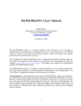
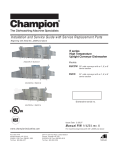
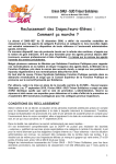
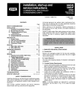
ANK INSTALLATION MANUAL NORTH AMERICAN REVISION Table of contents 1. INSTALLATION REQUIREMENTS…………………....….2 1.1. TOOLS AND PARTS…………………………………………………...…..2 1.2. SYSTEM REQUIRMENTS…………………………………………..……..2 1.3. LOCATION REQUIREMENTS………………………….………………..2 1.4 MINIMUM WATER VOLUME…………………………………………….2 1.5. MINIMUM CLEARANCE…………………………………………………2 1.6 ELECTRICAL REQUIREMENTS………………………………………….3 2. INSTALLATION INSTRUCTIONS………………….……...4 2.1 HYDRONIC CONNECTIONS………………………………………….4 2.2. ELECTRICAL CONNECTIONS………………………………………..5 2.2.1CABLE…………………………………………………………………..5 2.2.2. CONNECTING POWER SUPPLY…………………… ..……………5 3. TERMINAL BOARD CONNECTIONS…………………..6 4. CONTROLS AND COMMISSIONING…………………...6 4.1. PREPARATION FOR COMMISSIONING…………………………….6 4.2. MACHINE COMMISSIONING………………………….………...…....7 4.3. SEASON CHANGOVER……………………………..................................7 5. OPERATION 5.1. SET POINT IN COOLING MODE……………………………....7 5.2. SET POINT IN HEATING MODE……………………………....7 5.3. COMPRESSOR START-UP DELAY………………………...…....7 5.4. CIRCULATION PUMP…………………………………………...7 5.5.FAN SPEED CONTROL……………………………………….....7 5.6. ANTI-FREEZE ALARM……………………………........................7 5.7. WATER FLOW RATE ALARM……………………………...........8 6. MAINTENANCE…………………………………………....8 6.1. HYDRAULIC CIRCUIT…………………………….........................8 6.2. ELECTRICAL CIRCUIT CHECKS…………………………….....8 6.3. COOLING CIRCUIT CHECKS……………………………...........8 6.4. MECHANICAL CHECKS………………………………………...8 6.5.REFRIGERANT LOAD PROCEDURE………..………………....8 7. LIST OF CONTROLS……………………………….……………....9 8. TROUBLESHOOTING……………………………...…...11 WIRING DIAGRAM…………………………….........................12 WARRANTY……………………………...........................................13 GENERAL WARNING FOR THE INSTALLER The chiller must be installed by a qualified and trained technician. AERMEC will not assume any responsibility for damage due to failure to follow these instructions. Before beginning any operation, READ THESE INSTRUCTIONS CAREFULLY AND CARRY OUT THE SAFETY CHECKS TO REDUCE ALL RISK OF DANGER TO A MINIMUM. All the staff involved must have thorough knowledge of the operations and any dangers that may arise at the moment in which the installation operations are carried out. Vers. 1.1.15 1. INSTALLATION REQUIRMENTS These instructions are intended as a general guide only and do not supersede any national or local codes in any way. The installa‐ tion must comply with all state, and local codes as well as the National Electrical Code. The heat pump is designed and approved for outdoor use only. The heat pump must be installed with no duct work in the airstream. The outdoor fan is not designed to operate against any additional static pressure. 1.1. TOOLS AND PARTS Assemble the required tools before starting installation. Read and follow the instructions provided with any tools listed here. Tools Needed: Mechanical tools required by Plumbing or HVAC standards Wrenches, Screw Drivers, Hose, Glycol 1.3 LOCATION REQUIREMENTS This heat pump is designed to be located outdoors with sufficient clearance for free entrance to the inlet and discharge air openings. The location must also allow for adequate service access. See “Minimum Clearances.” Where possible, select a location for the heat pump which is shaded from the direct rays of the sun most of the time. North or east locations are usually most desirable. Position the heat pump to avoid direct contact with water, snow or ice from a roof line overhead. The heat pump must be installed on a solid, level mounting pad that will not settle or shift. Isolate the pad from the building structure to avoid possible transmission of sound or vibration from the heat pump into the conditioned space. The heat pump foundation should be raised to a minimum of 3 in. above finish grade. In areas which have prolonged periods of temperatures below freezing, and/or snowfall, the heat pump should be elevated above the average snow line. If heat pump is to be installed on a flat roof, it should be on a platform or other support which will raise the unit base pan 12 in. minimum above the surface of the flat roof. Parts Needed: Check local codes and HVAC supplier. Check existing electrical supply, and read “Electrical Requirements,” “Location Requirements,” “System Requirements” and “Connect Care should be taken to ensure free drainage of condensate Glycol Lines.” from defrost cycles. This will prevent ice accumulation. The heat pump should be located away from walkways to prevent 1.2 SYSTEM REQUIREMENTS: possible icing from defrost condensate. Aermec heat pump system are derived from actual laboratory Avoid placing the heat pump near areas such as sleeping testing of the equipment. It is recommended that all deisgn criteria quarters or study rooms. Normal operating sound levels may be met or exceeded to ensure proper operation and be objectionable if the heat pump is placed near certain efficient performance. rooms. A shift in sound type does occur during the defrost The designed system criteria are listed in the heat pump unit specification sheets and in the heat pump technical man‐ mode. The defrost mode generally lasts no longer than 5 ual minutes This heat pump has been factory charged with a quantity of refrigerant (R410A) 1.4 MINIMUM WATER VOLUME IMPORTANT: Refer to “Aermec System Water Volume Guide” (you can download it on aermec.us in tutorial books section) ANK heat pumps need a minimum volume of 35 gallons of water/glycol. If the version is an HA it has an internal 25 gallon tank so the system must contain a minimum of 10 additional gallons when all zones but the smallest are closed or not operating. (Only count the smallest zone volume along with the pipes to the manifold. If the heat pump does not have an internal buffer tank you must add 35 gallons in the system with a buffer tank or piping. 1.5 MINIMUM CLEARENCE 2 1.6 ELECTRICAL REQUIREMENTS IMPORTANT: Electrical wiring, disconnect means and over current protection are to be supplied by the installer. Refer to the rating plate for the maximum over current protection, minimum circuit ampacity, and operating voltage. See wiring diagram. Install an adequately sized branch circuit disconnect, per the NEC, within sight of and readily accessible from heat pump. The cable or conduit and fittings connected from the disconnect to the heat pump shall be rated for outdoor use. Check the heat pump rating plate and follow the appropriate instructions below. NOTE: All wiring must be suitable for outdoor use. Use copper conductors only. All field wiring must be done in accordance with National Electrical Code requirements, applicable requirements of UL, or local codes, where applicable. Electrical wiring, disconnect means and over current protection are to be supplied by the installer. Refer to the rating plate for the maximum over current protection, minimum circuit ampacity, and operating voltage. See wiring diagram. current 3 2 INSTALLATION INSTRUCTIONS This heat pump is shipped in one package, completely assembled and wired. The indoor controller is shipped in a separate carton when ordered. 1. Check the heat pump rating plate to confirm specifications are as ordered. 2. Upon receipt of equipment, carefully inspect it for possible shipping damage. Take special care to examine the unit inside the carton if the carton is damaged. If damage is found, it should be noted on the carrier’s freight bill. Damage claims should be filed with the carrier immediately. Claims of shortages should be filed with the seller within 5 days. NOTE: If any damages are discovered and reported to the carrier, do not install the unit because your claim may be denied. 2.1 HYDRONIC CONNECTIONS Water / glycol piping must be connected by a licensed, or certified technician using established procedures. IMPORTANT: Connecting water lines must be clean, properly sized (minimum 1 ¼ inch). Reducing fitting shall not be used Use care with the water / glycol lines during the installation process. If pex is used it can be cut by sharp objects. Do not remove the caps from the lines or system connection points until connections are ready to be completed. 1. Route the supply and return lines from the fittings on the indoor manifold or tank to the fittings on the heat pump. Run the lines in as direct a path as possible avoiding unnecessary turns and bends. 2. Ensure that both lines are insulated over the entire exposed length and that both supply and return lines are not in direct contact with floors, walls, duct work, floor joists, or other piping. 3. Flush the lines out with water 4.Pack insulating material around water/glycol lines where they penetrate the structure to protect the lines and to minimize vibration transmission. 5. Connect the supply and return lines, and tighten using two wrenches NOTE: Always use two wrenches when tightening any fittings. 4 ANK 030‐045‐050 H‐HP Air vent ANK 030‐045‐050 HA Air vent Air vent 2.2ELECTRICAL CONNECTIONS 2.2.1 CABLE The cable section shown in the table are recommended for maxi‐ mum lengths of 50m. For longer lengths or different cable laying, it is up to the designer to calculate the appropriate line switch, the power supply line as well as the connection to the earth wire and connection cables depending on: length type of cable absorption of the unit and the physical location ambient temperature. ATTENTION: The ANK heat pumps are completely wired at the factory a nd only require connection to the electrical mains, downstream from a unit switch, according to that envisioned by the Standards in force on this subject in the country of installation. It s also advised to check the following: The electrical mains features are suitable For the absorption values indicated in the electrical data table in technical manual. Also taking into consideration any other machines operating at the same time. The unit is only powered when installation has been completed (hydraulic and electric). Respect the connection indications of the phase, and ground wires. The power supply line must have a relevant protection mounted upstream against short circuits and dispersions to earth, which isolates the system with Respect to other utilities. The voltage must be within a tolerance of ±10% of the nominal power supply voltage of the machine (for unbalanced three‐phase unit max 3% between the phases). Whenever these parameters are not respected, contact the electric energy public body. For electric connections, use the cables with double isolation according to the Standards in force on this subject in the differentcountries. The use of an omnipolar magnet circuit breaker switch is mandatory, in compliance with the IEC‐EN Standards (contact opening at least 3 mm), with suitable cutoff power and differential protection on the basis of the electric data table shown below, installed as near as possible to the appliance. It is mandatory to make an effective earth connection. The manufacturer cannot be considered responsible for any damage caused by the lack of or ineffective appliance earth connection.For units with three‐phase power supply, check the correct connection of the phases. 5 Check the tightening of all power wire clamps on commissioning and after 30 days from start‐up. Subsequently, check the tightening of all the power clamps every six months. Loose terminals can cause overheating of the cables and components. 2.2.2 CONNECTING POWER SUPPLY Before connecting the unit to the power supply mains , en‐ sure that the switch is off Open the front panel Use the holes at the bottom on the framework for the main electric power supply cable and for the cables of the other external connections under the responsibility of the installer. It is forbidden to access with electric cables in positions not specifically envisioned in this manual. Avoid direct contact with not insulated copper piping and with compressor. Identify the clamps for the electric connection, always refer to the electric layout supplied with the unit. For the functional connection of the unit bring a power supply cable to the electric control board inside the unit and connect to the U‐N and PE clamps respecting (U) phase, (N) neutral, (PE) earth in case of single‐phase power supply (220V‐1~60Hz), Re‐position the inspection panels Ensure that all protections removed for the electric connec‐ tion have been restored before electrically powering the unit. Position the main system switch (external to the appliance) at “ON”. TO ACTIVATE TERMITAL BOARD 13POLE To activate terminal board set value of 9 PAN to 3. To get to this parameter enter password 030. SUMMER/WINTER REMOTE CONTROL (C/F) To prepare a summer/winter remote switch‐over device connect the device contact to the clamps 3 and 5 of the 13 POLE terminal board. ON/OFF CONTROL (IA) To prepare an ON/OFF remote switch‐over device connect the de‐ vice contact to clamps 4 and 5 of the 13 POLE terminal board. 3. TERMINAL BOARD CONNECTIONS Connections under the responsibility of the installer All connections to which reference is made in the following explanations are part of the 13 POLE removable terminal board situated inside the electric control panel and connected to the MODUCONTROL. There are two types of connections see wiring diagram at the end of the manual. REMOTE ALARM (AE) Remote indicator can acknowledge alarms, this is possible using clamps 6 and 7 of the 13 POLE terminal board, connect an acoustic or visual alarm signal device. REMOTE PANEL (TRA) To prepare a summer/winter switch‐over device, connect the de‐ vice contact to clamps 8 and 9 of the 13 POLE terminal board. CONTACTS FOR DOMESTIC HOT WATER DHW (TWS) To use a stand‐alone contacts for DHW device, connect to clamps 10 and 11 of the 13 POLE terminal board. CONTACT FOR BOILER CONTROL To prepare a boiler control, connect to contacts 12 and 13 of the 13 POLE terminal board. CONNECTION PR3 (ACCESSORY) If you should have the PR3 accessory, always connect it to the 13 POLE terminal board as shown below. Remember that the maxi‐ mum distance accepted is 150 mt. REMEMBER THAT THE PR3 AS WELL AS BEING CONNECTEDMUST BE ENABLED (see subsequent pages). 4. CONTROLS AND COMMISSIONING 4.1. PREPARATION FOR COMMISSIONING Before starting the unit make sure that: 1. All safety conditions have been respected 2. The unit is correctly fixed to the support surface 3. The minimum technical spaces have been respected; 4. The hydraulic connections have been made respecting the inlet and outlet 5. The hydraulic plant has been loaded and bled of the air. 6. The hydraulic circuit valves are open Commissioning must be performed with standard settings. Only when the inspection has been completed can the functioning Set Point values be changed. Before start‐up, power the unit for at least 12‐24 hours positioning the protection magnet circuit breaker switch and the door lock isolating switch at ON. Make sure that the control panel is off in order to allow the compressor sump oil to heat. 6 7. The electric connections have been made correctly 8. Check, that in models with three‐phase power supply, that the compressor noise level is not abnormal. If this is the case, invert a phase. 9. All electrical connections inside the unit have been checked 5. OPERATION 9. The voltage is within the tolerance of 10% of the unit nominal value 10. Earthing is correctly made. All electric and hydraulic connections are correctly tightened. 5.1. SET POINT IN COOLING MODE. PARAMETER 1STF (factory set)=7°C/44.9°F, ∆t=9°C. 4.2. MACHINE COMMISSIONING 5.2. SET POINT IN HEATING MODE. PARAMETER 3STC ‐ Close the electric control board hatch. (factory set) = 45C/113°F, ∆t = 9°C. ‐ Position the appliance master switch at ON. If the unit power supply is restored after a temporary interruption, the set mode will be kept in the memory. 5.3. COMPRESSOR START-UP DELAY Two functions have been prepared to prevent compressor start‐ups that are too close. ‐Make sure that the auxiliary switch contact (IA) (see wiring diagram) is open (if used, and the display LED (I)A must be off. ‐Press the ON key for 3 sec to switch the machine on. 4.3. SEASON CHANGEOVER, OPERATION PARAMETERS ‐ For every season change, check that the functioning limits lie within the proper limits. ‐ Check that the compressor input current is lower than the maximum indicated in the technical data table. ‐ Make sure that the voltage value lies within the pre‐fixed limits and that unbalance between the three phases (three‐phase power supply) is not above 3%. SEASON CHANGEOVER FROM PANEL ON MACHINE Access the USER SET list by touching the insert password key 000 (already displayed); just confirm by re‐pressing the key The parameter affected is the Sta, changing the value 0 and 1 will change the operation from cooling to heating accordingly. For further informa‐ tion refer to the USER MANUAL ‐ Minimum time from last switch‐off 180 seconds. ‐ Minimum time from last switch‐on 300 seconds. 5.4. CIRCULATION PUMP The circuit board delivers an output for pump management, which starts on commissioning and remains on for at least 150 seconds and controls the state of the probes. After the first 40 seconds of pump operation the water flow switch closes and the unit starts, when the water flow rate is in normal working conditions, the water flow rate alarm functions are acti‐ vated (differential pressure switch or flow meter). When the ma‐ chine enters stand‐by mode, the pump remains on for 30 sec and controls the flow meter or the pressure switch 5.5. FAN SPEED CONTROL DCPX ACCESSORY COOLING OPERATION AT LOW AMBIENT CONDITIONS AND HEATING OPERATION AT HIGH AMBIENT CONDITIONS. To allow correct functioning of the unit at different external tem‐ peratures, the MODUCONTROL by reading the pressure via the pressure probe, controls the rotation speed of the fans, thus allow‐ ing to increase and/or decrease heat exchange, keeping the con‐ densation or evaporation pressures more or less constant. The fan functions independently with respect to the compressor. Remem‐ ber that the DCPX is mandatory for the production of DHW. And cooling below 20°C/68°F. 5.6. ANTI-FREEZE ALARM The anti‐freeze alarm is never active if the machine is off or in stand ‐by mode. In order to prevent breakage of the plate heat exchanger SEASON CHANGEOVER FROM PR3 due to freezing of the water it contains, the MODUCONTROL stops Just act directly on the switch. The machine switches off automatically‐ the compressor if the temperature detected by the probe postioned and switches back‐on with the selected functioning mode. Advance based at the outlet of the heat exchanger and in inlet to the chiller is on the timeframe for the completion of works for the system. Prior to below +4°C/39°F. the work to be carried out by the AERMEC service personnel, all other THIS ANTI‐FREEZE SET TEMPERATURE CAN ONLY BE VARIED BY AN works (electrical and hydraulic hook‐ups, priming and bleeding of air AUTHORISED AFTER‐SALES CENTRE AND ONLY AFTER HAVING CHECKED from the system) must have been completed. THAT THERE IS ANTI‐FREEZE SOLUTION IN THE WATER SYSTEM. 7 The intervention of this alarm determines compressor stop and not pump block, which remains active along with the switch‐on of the resistance if installed. To restore normal functions the tem‐ perature of the outlet water must rise above +4°C/39°F. Rearm is man‐ ual. − Carry out the appropriate checks on the filter dryer to check effi‐ ciency WHENEVER THIS ALARM INTERVENES, WE ADVISE YOU CALL THE NEAR‐ EST AFTER‐SALES SERVICE IMMEDIATELY. 6.4. MECHANICAL CHECKS 5.7. WATER FLOW RATE ALARM The MODUCONTROL manages a water flow rate alarm controlled by the differential pressure switch installed in series on the machine. This type of safety device intervenes after the first 40 seconds of pump function‐ ing, if the water flow rate is not sufficient. The intervention of this alarm determines compressor and pump block. 6. MAINTENANCE Inspection, maintenance and eventual repair work must be carried out only by a legally qualified techni‐ cian. Lack of control/maintenance can cause damage to persons or things. All cleaning is prohibited until the unit has been disconnected from the electric power supply mains. Make sure there is no voltage present be‐ fore operating. Periodic maintenance is fundamental to keep the unit perfectly efficient under a functional and energetic point of view. It is therefore essential to carry out periodic yearly controls for the: 6.1. HYDRAULIC CIRCUIT − Refilling of water circuit − Check the ghtening of the screws the compressors and the elec‐ trical box, as well as the exterior panelling of the unit. Insufficient fastening can lead to undesired noise and undesired vibrations − Check the condi on of the structure. If there are any oxidised parts, treat with paint suitable to eliminate or reduce oxidation. 6.6. REFRIGERANT CHARGING PROCEDURE IT IS forbidden to CHARGE the circuit with a refrigerant gas different to the one indicated. Using a different refrigerant gas can cause serious damage to the compressor. The charging procedure is the following: − Empty and dry the en re cooling circuit using a vacuum pump connected to the low and high pressure socket until 10Pa/77 mi‐ crons is read on the vacuum meter. Wait a few minutes and check that this value does not rise above 50 Pa/362 microns. − Connect the refrigerant gas cylinder or a load cylinder to the ac‐ cess port on the low pressure line. − Charge the amount of refrigerant gas indicated on the appliance features plate. − Control of flow switch − A er a few hours of opera on, check that the liquid indicator indicates the dry circuit (dry‐green). In the case of partial loss, the circuit must be emptied completely before being re‐charged. − Bleed the air from the circuit. − The R410A refrigerant must only be charged in the liquid state. − Verify that the water flow rate to the evaporator is constant. − Func oning condi ons that are different to the nominal condi‐ tions can give rise to values that are greatly different. − Cleaning the water filter − Verify the thermal insula on of the hydraulic piping. − Check the percentage of glycol where necessary. 6.2. ELECTRIC CIRCUIT CHECKS − Safety efficiency − Electric supply voltage − Electrical Input − Connec on ghtness − Verify the opera on of the crankcase compressor heater 6.3. COOLING CIRCUIT CHECKS − State of compressor − Efficiency of the plate heat exchanger resistance if envisioned − Work pressure − Leak test for water ghtness control of the cooling circuit − Func oning of high and low pressure switches 8 − Leak tes ng must only be performed using R410A refrigerant gas, nitrogen and using a suitable leak detector. − In the refrigerant circuit it is prohibited to use oxygen or acetylene or other inflammable or poisonous gases because they are a cause of explosions or intoxication. 7. LIST OF CONTROLS FOR THE GUIDED PROCEDURE How to modify a parameter in the user menu: How to modify a parameter in the installer menu: To enter the USER menu press the key shown in (Fig.A). Once the key has been pressed the password must be inserted for access to the various menus. To access the user menu the password is 000 (which is the de‐ fault displayed); to modify the value of the password use the arrow keys. Once the correct password has been inserted, press the key shown in (Fig.A). The display shows the index of the USER parameter and a string of three characters that identify it. The string remains displayed for one second, after which it is replaced by the value relative to the parameter itself. To pass to the next parameter, use the arrow keys (Fig.B). To mod‐ ify a parameter, just select it, press the key shown in (Fig.A), modify the value using the arrow keys shown in (Fig.B). To confirm the modification press the key shown in (Fig.A) again. To enter the INSTALLER menu, press the key shown in (Fig.A).Once the key has been pressed the password must be insertedfor access to the various menus. To access the user menu the password is 030. To modify the value of the password use thearrow keys. Once the correct password has been inserted, press the key shown in (Fig.A). The dis‐ play shows the index of the INSTALLER parameter and a string of three characters that identify it. The string remains displayed for one sec‐ ond, after which it is replaced by the value relative to the parameter itself. To pass to the next parameter, use the arrow keys (Fig.B). To modify a parameter, just select it, press the key shown in (Fig.A), mod‐ ify the value using the arrow keys shown in (Fig.B). To confirm the modification press the key shown in (Fig.A) again. . 9 (1)What type of system terminals are used in the heating circuit? Reply Operations to be performed The unit is a cooling only model Go to question 2 Radiant panels (Floor, etc....) Set the parameter StC (index 3 USER menu) with the value of 35 C Fan coils or low temperature radiators Set the parameter StC (index 3 USER menu) with the value of 45°C(default value) Set the parameter StC (index 3 USER menu) with the value of 55 °C Other applications (2) Is the remote panel accessory installed (PR3) ? Reply Operations to be performed Not installed Go to question 3 Installed Set the parameter PAN (index 9 INSTALLER menu) with the appropriate value, selecting from: Value (1): • Season control piloted from the circuit board • ON/OFF control enabled from PR3 Value (2): • Season control enabled from PR3 • ON/OFF control from panel on machine Value (3): • Season control enabled from PR3 • ON/OFF control enabled from PR3 (3) Is the production of DHW envisioned? Reply Not envisioned Operations to be performed Go to question 5 Envisioned Set the parameter ASA (index A INSTALLER MENU) with the value (1) (4) Is a 3‐way diverter valve envisioned in the DHW production circuit? Reply Operations to be performed Not envisioned Go to question 5 Envisioned Set the parameter AAS (index C INSTALLER menu) with the appropriate value (in seconds). This parameter indicates the stand‐by tome for inversion of the 3‐way diverter valve on the DHW production system (5) Is a room thermostat installed? Reply Operations to be performed Not installed No operation Installed This parameter enables a digital clamp ID (indicated on the circuit board with the code TRA) to which a room thermostat must be connected, used to disable the compressors and the integrative resistances. Set the parameter trA (index D INSTALLER menu), with the appropriate value, selecting from: Value (1 or 2): Clamp ENABLED Value (0 or 3): Clamp DISABLED Remember that the OPEN state on the clamp represents: • the compressors and resistances block function if the parameter is set at 1 • the compressors, pumps and resistances block function if the parameter is set at 2 • represents the pump alarm (as in the previous software version), if the pa‐ rameter is set at the value 3 . 10 8. TROUBLESHOOTING ANOMALY . The chiller does not start‐up Insufficient yield Noisy compressor Noise and vibrations The compressor stops due to intervention of the safety controls High discharge pressure Low discharge pressure High intake pressure Low intake pressure Flow switch error 104 11 CAUSE No electric voltage Master switch at OFF Remote switch at OFF (if present) Control panel at OFF Main switch at OFF Compressor magnet circuit breaker at OFF SOLUTION Check the presence of voltage Check the safety systems upstream from the appliance Position at ON Power supply voltage too low Check power supply line Remote control switch coil broken Circuit board broken Peak condenser broken Compressor broken Replace the component No refrigerant Appliance dimensioning Functioning outside of operational limits Check Liquid refrigerant returns to the compressor Inadequate fixing of the piping connections Check Fastened properly Phase inverted, compressor moving backwards (in three‐phase versions only) Contacts between metal bodies Invert a phase Weak rest Restore Loose screws Tighten the screws High pressure Low pressure Low voltage Poor connections, relay contacts Functioning outside of operational limits Check Check Pressure switch dysfunction Replace the component Circuit breaker protection interruption Check power supply voltage Check electric isolation of the windings High external air temperature High water input temperature Check Insufficient air flow Insufficient water flow Check fan functioning Check pump functioning Fan regulation anomalous functioning Check Air in the hydraulic system Bleed Excessive gas load Check High external air temperature High water input temperature Check Insufficient air flow Insufficient water flow Empty and restore the gas load Fan regulation anomalous functioning Check Air in the hydraulic system Bleed Excessive gas load Check High external air temperature High water input temperature Thermostatic expansion valve too open or dam‐aged Check Low external air temperature Low water input temperature Thermostatic expansion valve damaged or blocked Water filter blocked Plate heat exchanger blocked Check Insufficient air flow Insufficient water flow Check fan functioning Check pump functioning Loose wire on the pump Clogged filter Air in the system, low pressure in the system loop Check the pump Clean filter Bleed the air A 2 2 3 C/F DISEGNATO ATTENTION! 4 3 DATA 6 DISEGN. IADATA 3 APPROV. AE De Togni 06/12/2012 Bovo 06/12/2012 MAX 1A 230V 7 Terminals 6 and 7 provide basic insulation opposed to main power supply line, all others give a reinforced insulation. REF. CEI EN 60335-2-40 5 VERIFICATO T 8 9 4 1 0 T 1 1 1 2 1 3 5 Boiler contact control MAX 1A 230V Boiler control 5 3.4 3.4 33 3.3 34 3.2 31 3.3 2.4 32 6 2.8 17 3.2 25 3.3 29 3.2 30 3.2 26 1.7 27 8 1.8 7 7 Contact between 10-11 opened = unit in normal function closed = unit in DHW mode Comando a distanza 6 Remote control 4336825 ANK 030 - 050 230V 60Hz 7 = + 8 8 30 DI FOGL. 5 4 In DHW mode using parameter E requires parameter F to b e set to 180 sec to allow the 3 way valve to open or close. T he maximum setting is 5 minuts. When the unit is in standard mode the setpoint is in menu u ser (cooling or heating). When the units is in DHW mode th e setpoint parameter E is in user menu. Th DHW is active if in password 30 parameter A os set to 1 28 M5S1-1 M5S1-2 M7S-7 M7S-5 M7S-8 M1S-8 M1-8 M7-5 M7-6 M7S-3 M7S-4 1RCR 2RCR 1 DATA 4 TERMINAL BOARD CONNECTIONS To enable these contacts p assword 30 parameter PAN settet to 3 Contact between 4-5 opened = unit off closed = unit on MODIFICA Contact between 3-5 opened = unit oin heating closed = unit on 1 RCR2 B REV. RCR1 C D E F NON E' PERMESSO CONSEGNARE A TERZI O RIPRODURRE QUESTO DOCUMENTO NE' UTILIZZARE IL CONTENUTO O RENDERLO COMUNQUE NOTO A TERZI SENZA LA NOSTRA AUTORIZZAZIONE ESPLICITA. OGNI INFRAZIONE COMPORTA IL RISARCIMENTO DEI DANNI SUBITI. E' FATTA RISERVA DI TUTTI I DIRITTI DERIVANTI DA BREVETTI O MODELLI PROGETTO: NOME FILE: 4336825_00.sch TIPICO: Elettrico A B C D E F Mits Airconditioning Inc Master Distributor in North America for Aermec S.P.A. Limited Warranty Information and Registration This warranty is extended by Mits Airconditioning Inc (hereafter referred to as MITS) to the final purchaser. MITS warrants it’s products to be free of defects in materials and workmanship at the time of original purchase and for subsequent periods of time as described below. Aermec Chiller and Heat Pumps parts are warranted to be free from manufacturing defects for up to 12 months from the date of installation. The compressor is warranted for 5 years from the date of installation for residential application and 1 year for commercial applications. Aermec Fan Coil parts are warranted to be free from manufacturing defects up to 12 months from date of installation. Aermec Accessories – valves, storage tank, expansion tank, and control are warranted to be free from defects for up to 12 months from the date of original installation. If, during the period of warranty, the products listed prove defective under normal use and service due to improper materials or workmanship as determined by MITS, the company will at its sole discretion replace the defective part or component. Conditions: In the event MITS replaces a part or component, the repaired or replaced product shall be warranted under the original limited warranty for the remainder of the original warranty period. The warranty does not cover any failure of components not supplied by MITS, nor does it cover failure of any part due to misuse (including neglect, improper installation, repair alteration, modification, or adjustment). Damage caused by freezing, corrosion, and fouling is not covered under this warranty. There are no other express warranties, whether written or oral other than this printed limited warranty. All implied warranties, including without limitation the implied warranties or merchantability or fitness for a particular purpose, are limited to the duration of this limited warranty. In no way shall the company be liable for incidental or consequential damages of any nature whatsoever, including but not limited to lost profits or commercial loss, to the full extent those damages can be disclaimed by law. 1608 Bonhill Road, Mississauga, On, L5T 1C7 Toll Free: 1-800-567-2221(Canada) Toll Free: 1-888-567-2227 (USA) www.aermec.ca www.aermec.us The technical data given on the following documentation are not binding. Aermec reserves the right to apply at any time all the modifications deemed necessary for improving the product. 1608 Bonhill Road | Mississauga | ON | CA | L5T 1C7 Phone 905.564.2221 Canada: www.aermec.ca | Toll Free 1.800.567.2221 US: www.aermec.us | Toll Free 1.888.567.2227