1
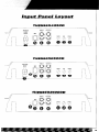
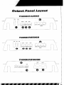
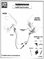
^“-ll”---^..“-.~~
_, ^, ,__^
i
CONGRATULATIONS
on your purchase of a new MTX
Thunder Amplifier! MTX has long
been the industry leader in mobile
enclosures and speakers, and we
have reached new heights with the
development of the new MTX Thunder
amplifiers. You couldn’t have chosen
a more reliable, powerful, or better
performing amplifier - In fact, we
back up every Thunder amplifier with
a three-year warranty if installed by
an authorized MTX retailer (see the
warranty statement on page 34).
Your new MTX Thunder amplifier was
designed, built and thoroughly tested at our
state-of-the-art electronics manufacturing
facility in Phoenix, Arizona. We manufacture
every amplifier using the latest intelligent
Surface Mount Technology. Some of the
advantages of the new design are its significant improvements to the amplifier’s electrical and mechanical properties. ISMT
devices feature substantially shorter internal
and external lead lengths. This reduces stray
capacitance and inductance, which results
in cleaner and more accurate musical reproduction with significantly less noise interference. The ISMT mounter produces amplifier
boards with smaller and lighter components,
which are more resistant to vibrations inherent in the automotive environment.
A word about power ratings.It is importantfor you
to know how they stack up. MTX has chosenthe
most honest, most conservativeway to rate our
amps.We show you the RMSpower,at 12.5volts,
and dynamicpower at 14.4volts. However,we go
above and beyondthe call of duty. We test each
amplifier. The technician recordsthe “actual”
power output, and records this number on your
Certified Performance Certificate. The amplifier
must meet or exceed the rated specification
beforewe’ll ship it. No questions.No exceptions.
We want to ensure you get continuous
high performance from your MTX Thunder
amplifier, so we recommend that you
have it professionally installed by your
authorized MTX dealer.
HOW TO USETHIS MANUAL
If you are installing this amplifier yourself, we
recommend that you read the manual coverto-cover before you install it. Familiarize
yourself with the features and details on the
input and output panels. Make sure you have
all the equipment you need. Sample installation diagrams may be found on our website:
WWW.MTXAUDIO.COM
If you have any questions, write or call us at:
MTX
4545E.BaselineRd.
Phoenix,AZ 85040
l-602-438-4545
P
I-800~CALL-MTX
technicalQmtxaudio.com
www.mtxaudio.com
Registeryour warranty online
Features
l
l
l
l
l
l
l
l
l
l
l
l
l
l
l
l
l
l
l
l
Intelligent Surface Mount Technology
Patented PWM MOSFET Switching Power Supply (#5,598,325)
Adaptive Class D Technology
High Powered Transformer
High Powered stacked inductor
Pure N-Channel Design
Doubles power into 2 ohms
Real lime Computerized Protection Circuit
Color-coded wire harness for speaker-level input installation on Thunder4250Dand 65000
Smart-EngageTMauto turn on for easy integration with factory head units Thunder4250Dand 6500D
Acoustically Seamless Turn-on/Turn-off (i.e. no noise)
Variable frequency low-pass crossover, 40Hz to 200Hz. 24dB/octave low pass
Defeatable compression circuit included on Thunder6500D and Thunder810000
Continuously adjustable and defeatable Bass EQ enhancement circuitry, centered at 40Hz
Low level inputs
EBC - External Bass Control Port with an additional 3dB of gain when used, and 23dB attenuation
Adjustable input sensitivity
Buffered RCA Outputs for daisy-chaining additional bass amplifiers
Nickel-plated, heavy duty terminal block type connectors
Unique rubber Insulated Iso-FeettM
Smecifications
THUNDER4250D
THUNDER81000D
RMS Power measuredat 12.5Volts DC:
125Watts x 1 into a 4 Ohmload with less than 1%ThdrN
250Watts x I into a 2 Ohmload with less than 1%ThdtN
DynamicPower measuredat 14.4Volts DC
200Watts x 1 into a 4 Ohmload
350Watts x 1 into a 2 Ohmload
S~goalto Noise Ratio: >lOOdBA-Welghted
DampingFactor:,200
FrequencyResponse:ZOHz-200Hz
MaximumInput: avrms
Thunder E(1:Variable Bass Boost IO-lad61centered at 40Hz
Crossover: Variable4OHzto 200Hz.24dBioctavelow pass
Dimensions:7” x 9 15” x 2” (17.8cmx 24.&m x 5.lcm)
9.9’ x 9.75” x 2.1” (23.6cmx 24&m x 5.3cm)Including lsoFe@
RMS Power measuredat 12.5Volts DC:
500Watts x I into a 4 Ohmload with less than 2% ThdtN
1000Watts x I into a 2 Ohmload with less than 2% ThdtN
OynamfcPower measuredat 14.4Volts DC
a50Watts x I into a 4 Ohmload
1500Watts x 1 into a 2 Ohmload
Signalto Noise Ratio: tlOOdB A-Welghted
DampIngFactor:>I00
FrequencyResponse:ZOHz-200Hz
MaxImumInput: BVrms
Thunder E(1:Variable Bass Boost IO-l8dB)centered at4OHz
Crossover: Variable40Hzto 2WHz.24dBioctavelow pass
0imenslons:lM” x 9.75” x 2”.(40.lcm x 24.8cmx 5.lcm)
17.K x 9.W x 2.1’ I45 2cm x 24.8cmx 5.3cm)Including IsoFeerM
RecommendedFuse= 150A
THUNDER6500D
RMS Power measuredat 12.5Volts DC:
250Watts x I into a 4 Ohmload with less than 1%ThdtN
500Watts x 1 mto a 2 Ohmload with less than I% ThdtN
DynamicPower measuredat 14.4Volts DC
450Watts x I mto a 4 Ohmload
775Watts x I mto a 2 Ohmload
Signalto Noise Ratio: >lOOdBA-Welghted
DampingFactor: ,200
FrequencyResponse:ZOHz-200Hz
MaximumInput: BVrms
Thunder EtI Variable Bass Boost IO-18dBlcentered at40Hz
Crossover: Variable40Hzto 2WHz.24dBloctavelow pass
Dimensions:11.5”x 9.75” x 2” (29.2cmx 24.8cmx 5.lcm)
13.9”x 9.75” x 2.1” (36.6cmx 24.8cmx 5.3cm)Including lsoFeeCM
1. Gain Controls -These controls are used to match the input sensitivity of the amplifier to the particular
source unit that you are using. The controls are factory set to IVrms.
2. Thunder EQ - This equalization circuit is used to enhance the low frequency response of the vehicle’s
interior. With up to 18 dB of boost and centered at 40Hz, the Bass EQ can be adjusted to meet your own
personal taste.
3. Frequency Control -This control is continuously adjustable from 40Hzthrough 200Hzat 24dB per octave.
Factory setting is at 40Hz.
4. RCA Input Jacks - RCAtype input jacks for use with source units that have RCA or Line Level Outputs.
A source unit with a minimum output level of 200mV is required for proper operation. However, this input
will accept levels up to 8Vrms.
5. EBC 2- The EBC, or Electronic Bass Control, allows a remote bass control to be adjusted from the driver’s seat, If the optional EBC is installed, the bass level will be able to be adjusted to overcome noise and
other interference. With EBC 2 multiple amplifiers can be controlled.
6. RCA-Output Jacks-These RCA outputs allow for a signal to be sent to other amplifiers in a daisy-chain
configuration. The RCAoutputs also allow for multiple bass amplifiers to be level controlled using one EBC.
7. Speaker level Inputs - This input will allow the Thunder425D and 6500Dto operate from source units
with speaker-level outputs. Output speaker leads from the source unit should be tied directly to the wire
harness provided with the amplifier.
Wire harness color codes:
Grey / Black = Source units right negative (-)
Solid Grey = Source units right positive (t)
White / Black = Source units left negative (-)
Solid White = Source units left positive (t)
With the Smart-EngageTMauto-turn circuit, a remote turn-on wire is not necessary when connecting the
speaker-level input wire harness to a high powered source unit. The amplifier will automatically turn on
when music is received.
8. Compression Circuit - This new circuit, found on the Thunder6500D and ThunderSlOOOD,
prevents the amplifier from going into clipping, even at high SPL levels. The compression circuit allows the
listener to play the amplifier at high volume levels, yet protects the speakers against the potential damage
that can occur during dynamic musical passages. The circuit is switchable on/off, for those SPL competitors who run their amplifiers into clipping on purpose. Warning; Damage to speakers may occur when the
compression circuit is in the off position.
1nm.d
Panel
Lavout
1. Fuses-Forconvenience,all amplifiersutilizeATCtype fuses. Forcontinuedprotectionin the eventthat a fuse blows,
replacethe fuse only with the samevalue.
Caution - The power fuses on the amp are for protecting the amp against overdrive. To protect the vehicle’s
electrical system,an additionalfuse is requiredwithin 18” of the battery on the 12Vt cable.
Thunder42500- 20Ax 2
Thunder65OOD
- 25Ax 3
Thunder81000D - 150Amps (not supplied)
2. Power Terminal -This terminal is where the power source of the vehicle is connected. The 12Vt must be connected directly to the positive battery post. It is highly recommendedthat you place an additionalfuse within 18”
of the battery connection, Be sure to use the correct gauge of power cable! If wire of insufficient size is used,
there will be a voltage drop and the amp will starve, causing poor performance. In an extreme case,the amp may
shut down due to the low battery voltage protection feature. The terminal closest to the fuse(s) is where the power
cable with connector should be installed. Be sure to makeyour connection clean to avoid any shortingto the other
terminals. Always double check all of the connectionsfor any discrepancies.08
Thunder42500 - 6-8 Gauge
Thunder6500D - 4-6 Gauge
Thunder81000D- l/O Gauge only
3. RemoteTerminal-This is the wire thatturns the amplifieron andoff. Thisterminal connectsto the ampturn-on lead
or the power antennalead comingfrom the source unit. If the source unit doesn’t have one of these wires, you can
either run a wire to the battery with a switch or use an ignition controlledwire to power up the amp. If you use the
ignition controlled wire, be aware that the amplifier will be on, as long as the car is on. When using the Smart
Engage” feature, a high poweredradio, and speakerlevel inputsit is not necessaryto connectthe RemoteTerminal.
4. GroundTerminal-The groundterminal connectsthe amplifierto the vehicle ground. Be sureto usethe same size
wire gaugeor larger as the t12V connection. A strong groundpoint is very important. A little screw throughthe body
is not acceptable. The cable should be as short as possibleand connectedto the chassisof the vehicle. The contact
point should be free of paint and debris for best results. All precautionsfor the 12Vt connectionapplyto this connection as well.
5.PowerLED(topoi heatsink)-A lighted LEDindicates that power has been applied to the amplifier. t12V from the
battery to the tBAll terminal (#lo) and t12V from a switched ignition or remote lead from a head unit. An
unlighted LEDindicates power has been removed or the amplifier has overheated. In the case of the overheat
condition, the amplifier will turn back on after it cools down.
P
6. 4 Term Block- The t and - terminals connect the speaker to the amplifier.
impedance is allowed.
2 ohm minimum
Outnut
Panel
Lavout
Adiustina
the?
Tvmical
Sneaker
Wirinq
Confiuurations
Gain
1. Turn the gain control on the amplifier all the way down.
Mono Amplifier
Impedance Requirement
2. Turn up the volume control on the source unit to
approximately 3/4 of maximum.
2 ohm minimum
3. Adjustthe gain control on the amplifier until audible distortion occurs.
4. Adjust the gain control down until audible distortion disappears.
5. The amplifier is now calibrated to the output of the
source unit.
Definitions
Common
of
Terms
The following list of terms with their definitions is offered as
help in understanding the set-up and operation of your
amplifier.
1. Crossover fxover) - an electrical filter with hrgh-pass or
low-pass characteristics that divides the frequency range
into playable bands for certain speakers. Subwoofers, midbass, midrange and tweeters are all designed to play different frequencies and should do so to avoid damage. The
xover point is where the playable frequencies cross from
one speaker to the next at -3dB below reference level.
2. Full-range - refers to signals which cover the entire audio
frequency span from 20Hzto 20kHz.
3. High-pass - simply put, this blocks lower frequencies
which damage smaller speakers, and passes the higher
frequencies for smaller speakers like the midrange and
tweeter.
4. Low-pass-You got it, this is the inverse of a high-pass. It
blocks higher frequencies and passes the playable lower
frequencies to the larger speakers, like subwoofers.
5. Impedance - the resistance to the flow of current in an
alternating current circuit (such as with music). Line level
circuits are typically a high impedance of several thousand
ohms, while speaker level circuits are usually a low impedance of a few ohms.
6. Line level - The tYpe of signal produced at the outputs of
tape decks, CD tuners, preamplifiers, etc., with a typical
value of a volt or less in a high impedance circuit.
7. Speaker level - The type of output that is meant to drive
speaker= These signals are sometimes called high level
and are usually connected by two conductor speaker wires.
8. Signal - The signal of an audio system is what is heard
from the speakers. These signals may be high pass, low
pass or full-range.
We don’t have enough space for Electronics 101,so if you
have a good, bad or amusing question, please call us TOLL
FREEat 800-CALL-MTX!(800-225-5689)
Troubleshooting
Guide
Readthis if youwannabe a do-it-yourselfer-- or give us a callat I-BOO-CALLMTX
&!A!&
No LEDindication
No t12V at remoteconnection
Not12V at Powerconnection
Supplyt12Vto terminal
Insufficientgroundconnection
Verifygroundconnection
Blownpowerfuse
LEDon, no output
Volumeon headunit off
Speakerconnectionsnot made
Gaincontrolon amplifieroff
Signalprocessingunitsoff
All speakersblown
Outputdistorted
Headunit volumesettoo high
Amplifiergainsettoo high
Balancereversed
Speakerswired L t R reversed
RCAinputsreversed
Somebalancereversed
&&jLo
Supplyt12Vto terminal
SomeSpeakerswired L t R
Replacefuse
Increasevolumeon headunit
Makespeakerconnections
Turnup gain
Applypowerto signalprocessor
Replacespeakers
Lowerheadunitvolume
Loweramplifiergain
Wire speakerswith correctorientation
ReverseRCAinputs
Wire speakerswith correctorientation
reversed
SomeRCAinputsreversed
ReverseappropriateRCAinputs
Bassis boomy
ThunderEQtoo high
Bassis weak
ThunderEQtoo low
Raisesetting
Speakerswired out
Wirewith correctphase
of phase
Not usingMTXwoofers
Blowingfuses
Excessiveoutputlevels
Amplifierdefective
Lowersetting
BuyMTXwoofers
Lowervolume
Returnfor service
Warranty
All MTX Thunder Amplifiers purchased in the USA are guaranteed against defects in
material and workmanship for a period of three years from the date purchased by the
end user, if the amplifier is installed by an authorized MTX dealer (one year, if
installed by the consumer). This warranty is limited to the original retail purchaser of
product. MTX disclaims any liability for the other incurred damages resulting from
product defects. Any expenses incurred in the removal and reinstallation of
amplifiers are not covered by this warranty. MTX’s total liability will not exceed the
purchase price of the amplifier. This warranty is valid only in the USA.
To ensure efficiency and full benefit on any warranty claim during the warranty
period stated above, MTX requests the return of the warranty registration card,
completed in full immediately following purchase. Proof of purchase must be
provided at time of warranty claim. If there is no proof of purchase provided with the
warranty claim, MTX reserves the right not to honor the warranty set forth above.
Therefore, labor and parts may be charged to you.
This warranty does not apply to product exterior and cosmetics. Misuse, abnormal
service or handling, improper alterations or modifications in design or construction
void this warranty.
No sales personnel of the seller, or any other person is authorized to make any
warranties other than those described above or to extend the duration of any
warranties on behalf of MTX beyond the time period described above.
For Warranty Inquiries, please call:
l-800-225-5689
l-602-438-4545
MTX
4545 E. Baseline Rd.
Phoenix, Arizona 85040
Register Warranty On-line:
www.mtxaudio.com
Please fold and seal with tape
WARRANTYREGlSTRATlON&CUSTOMERSURVEY
NAME
AGE
PHONE
ADDRESS
OCCUPATION
CITY
DEALERNAME
MTXMODELNO.
INSTALLED
BY
DATEPURCHASED
YEAR
VEHICLE
TYPE
1. WASTHISUNIT
MAKE
CI Purchased
for personaluse
MODEL
0
Received
as a gift
2. HOWDIDYOUFIRSTLEARNOFMTX?
m Newspaper
0 Catalog
0 TV
0 Dealer
D Radio
m Friend/Family 0 Storedisplay
CarandTrack RollingStone Lowrider
CI Magazine
(Circlethemagazine) MotorTrend
Truckin’ Autosound
andSecurity CarSound CarAudioandElectronics CarStereoReview
Q Other
3. ISTHIS:
D Yourfirstcarstereo CI Replacement/Upgrade
4. WHATWASTHEMAINREASON
YOUSELECTED
THISMTXPRODUCT?
Ll DealerrecommendationB MTXName/reputation
a Friend/family
recommendation
0 Price
D Other
U Sound
a Product
Appeal
5. WHATARETHREETHINGSYOULIKEMOSTABOUTTHISMTXPRODUCT?
m BassReproduction
It SoundQuality
U Powerhandling
It Styling
D Durability
0 Installation
Flexibility
6. HOWSATISFIED
AREYOUWITHTHISPRODUCT?
13 VerySatisfied a Satisfied c3 Neutral
7. WHEREDOYOUBUYYOURTAPESANDCD’S?
COMMENTS
CIINotSatisfied
TiiMW#f~E~~~OOOD
Amplifier Input Connections
AMPLIFIER
CAR STEREO
(SOURCE UNIT)
Remote/Power Antenna
Turn-On Wire
REQUIRED INSTALLATION
TOOLS:
Power Drill
Adjustible
For installation
options go to www.mtxauciio.com
Wrench
l
Crimpers
Utility Knife
l
Screw Driver
r
r,,~~~E~S10000
Amplifier Output Connections
AMPLIFIER
1
Connect to Car Stereo
Remote/Power Antenna
Turn-On Wire
Ground To Metal
Power: l/O AWG. Ground: l/O AWG.
Disconnect
Battery Negative (-) Cable
Prior to Installing Amplifier
CAUTION: This amplifier may draw in excess of 150 Amps of current.
Upgrading the vehicle’s factory battery and alternator is required.
(For specific details, contact your local authorized MTX dealer, or call l-800~CALL-MTX.)
For installation options go to mtxaudio.com
Remove Paint J
from Metal