1
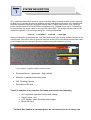
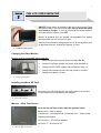
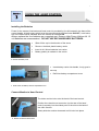
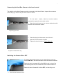
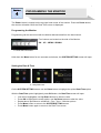
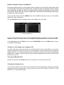
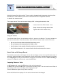
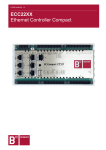
1
BRITE STAR
opto-electronics
90° LONGREACH INSPECTION CAMERA
WITH
VIDEO & IMAGE RECORDING
OPERATING MANUAL
November 2015
email: [email protected] Website: http:// www.starweb.com.au
Rev: 2H.
2
TABLE OF CONTENTS
Section
Description
Page
Section 1
System Description
3
Section 2
The LCD Video Monitor
4
Section 3
Using the Hand Control
5-6
Section 4
Programming the Monitor
7
Section 5
Using the Inspection Camera
8
Section 6
Discontinuing Use
9
Section 7
Trouble Shooting
11
Section 8
Notes
12
TABLE OF DIAGRAMS
No.
1
2
3
4
5
6
7
8
LongReach vs. Nest Box Camera
LCD wireless Monitor
Charging the Monitor
Installing the Micro SD Card
Monitor Real Time Screen
Monitor mounted on Hand Control
Remove battery cover
Hand Control battery carrier & cover
Page
3
4
4
4
6
5
5
5
No.
9
10
11
12
13
14
15
16
Align the camera detent
Tighten retainer ring
Camera ON/OFF & illuminator switch
Monitor control buttons
Setting Date & Time
Image & Video Playback
Rotating Camera tube
Page
6
6
6
7
7
8
9
3
Section
1
SYSTEM DESCRIPTION
90° LongReach Inspection Camera is a pole mountable video recording camera system designed
to allow you to navigate through tree foliage & access areas beyond the reach of our standard 90°
Nest Box Inspection Camera. LongReach camera tube is 700mm long has two Cree 1Wa high
power led illuminators & is LOOK DOWN configuration only. Suitable for use up to 7 metres high
or special order with longer cable for use up to 20 metres high. The orange camera head can be
rotated through 360° in its mount providing four viewing perspectives:Look up - Look down – Look left – Look right
Massive illumination provided by two Cree 1Wa high power light emitting diodes mounted on the
camera tube. Live colour video is viewed in real time on the LCD monitor which records either video
or still images to a micro sd card. Minimum nest box entry hole diameter is 27mm.
1. Size comparison -LongReach & Nest Box Inspection Cameras
Extended Reach – lightweight – high visibility
Attaches to standard extension poles
360° Rotating Camera
Records to µSD card
The kit is supplied in a protective field case and includes the following:
•
•
•
•
90° LongReach Inspection Camera with cabling
Hand Control Unit
LCD Monitor/ Video Recorder with charger
Micro SD Card
The Nest Box Camera is not waterproof - do not immerse or use in heavy rain
4
Section
2
THE LCD VIDEO MONITOR
ON/OFF Power button is located on the top of the monitor. Press
the button briefly to turn the monitor ON. Do not switch ON while
connected to charger. To turn off, hold down the power button 3
seconds until the monitor turns OFF.
Monitor is powered from an internal, rechargeable LiOn battery
which provides up to 2 hours of run time.
Video monitor should be charged prior to use & recharged as soon
as practical after use; charge time approx. 3 hours.
2.
LCD Wireless Video Monitor
Charging the Video Monitor
Monitor must be turned OFF before charging
Insert charger lead plug into socket marked “DC 5V”
Connect Plug Pack charger into power point & switch on
Charge until the “RED” charge light on Monitor goes out
Charge led located front left hand top corner on monitor
Charge time approx, 3 hours
3.
Charging the Monitor
Installing the Micro SD Card
Insert the micro SD Card into the slot on the side of the monitor.
Correct alignment is indicated by the diagram.
4.
Micro SD Card slot
Monitor – Real Time Screen
Icons on the real time screen indicate systems status.
Battery Icon - state of charge
Camera Icon - still image mode (Camcorder Icon – video mode)
Date time information
SD Card Icon – SD Card is installed
SD Card “F” – SD Card is full
5.
Monitor Real Time Screen
5
Section
3
USING THE HAND CONTROL
Installing the Batteries
Power for the camera, illuminator and hand control is provided by four AA located in the base of the
control handle. A black rotary switch turns the camera and the led illuminator ON/ OFF, a red led on
top of the hand control indicates when the camera is switched ON.
Always replace the four batteries as a complete set. Extreme High Power Lithium AA 1.5
volt batteries are recommended:- DO NOT USE RECHARGEABLE BATTERIES.
Slide off the cap in the direction of the arrow
Remove the black plastic battery carrier
Insert 4 AA lithium batteries into carrier
Battery polarity is marked on the carrier
6. Remove the battery cover
Insert battery carrier into handle, it only goes in
one way
Refit blue battery compartment cover
7. Hand Control, AA battery carrier & compartment cover
Connect Monitor to Hand Control
The video monitor locks onto the back of the hand control.
Position the raised mount connector (on the rear of the hand
control) squarely into the widest point of the slot on the back of
the video monitor.
Gently slide the monitor downward until it locks into place.
8. Monitor mounted on Hand Control
6
Connecting the Nest Box Camera to the hand control
The cable from the Nest Camera must be connected to the Hand Control. Inspect the connector
socket & plug to ensure they are clear of dirt or debris.
On the hand
control, slide the knurled retainer
rearward to expose the connector socket
Align the keyed tongue on the camera cable plug with
the slot in the connector socket
9. Align the plug & socket
Press the plug into the socket, do not force it
Slide the knurled retainer forward
Tighten the knurled retainer finger tight only
10. Tighten the knurled retainer ring
Switching the Camera ON or OFF
The black rotary trigger switch, on the Hand Control, turns the
camera ON/ OFF. The led illuminator comes ON with the camera.
Rotate the switch rearward till it clicks ON, the led on top of the
hand control glows red, the white leds on the camera will be lit.
Rotate the switch forward till it clicks OFF, red led will go out.
11. Camera ON/ OFF & illuminator Switch
7
Section
4
PROGRAMMING THE MONITOR
The Power button is located on the top right hand corner of the monitor. Press the Power button,
the monitor will switch ON & the Real Time screen is displayed.
Programming the Monitor
Programming can be carried out with the Monitor disconnected from the hand control.
Four buttons are located on the side of the Monitor.
OK – UP – MENU & DOWN.
12. Monitor side control buttons
Hold down the Menu button for two seconds and release, the SYSTEM SETTING screen will open.
Setting the Date & Time
13. Setting Date & Time
On the SYSTEM SETTING screen use the Down button to highlight the yellow Date/Time option
With the Date/Time option highlighted, press OK button, the Date/Time screen will open.
•
•
•
•
•
Year will be highlighted; use Up Down buttons to alter the value
Press OK to highlight the month option; use Up Down buttons to alter the value
Repeat above procedure to edit Month – Day – Hour – Minutes options
Press Menu button to return to the SYSTEM SETTING screen
Press Menu button again to return to the Real Time screen
8
Playback images/ video on the Monitor
Previously captured video or still images can be viewed on the monitor; the monitor does
not need to be connected to the hand control. Images & videos are stored in folders, folders
are identified by the date on which the images were recorded and displayed in year month
date format. Each folder will contain multiple files; individual files are identified by the time
at which they were recorded.
On the real-time screen press the MENU button; the PLAYBACK screen will open. A list of folders
identified by date is displayed.
Use the Up Down buttons to highlight a folder, press OK to open the folder.
14. Image & Video Playback
Images are identified by time stamp. Use the Up Down buttons to highlight an image press OK to
display the image. Press OK to return to the image list & Up Down buttons to select other image.
To exit playback mode, press Menu to return to the PLAYBACK screen, press Menu again to return
to the REAL TIME display.
Transfer or view images on a Laptop or PC
The Micro SD card can be read directly by computers with a built in card reader or by using a
separate USB SD card reader & the micro to sd card adapter provided. Windows will auto detect &
read the card when it is inserted; images can be viewed directly, video can be viewed using Windows
Media Player. Images or video files can be copied, drag & dropped directly from the micro SD card
to folders on your PC.
Turning the Monitor OFF
Depress & hold down the Power button for four seconds, the monitor will switch Off.
Cleaning the Camera Lens
The round lens, below the two leds, can be cleaned using a soft optical lens cleaning cloth lightly
moistened with lens cleaning fluid. Use light pressure & DO NOT SPRAY OR APPLY FLUID
DIRECTLY TO THE GLASS LENS.
9
Section
5
USING THE INSPECTION CAMERA SYSTEM
Hold the Camera firmly by the white T piece; position threaded end of extension pole into yellow
threaded port, rotate extension pole until it is well secured to the LongReach Camera.
To Rotate the Camera Head
The orange camera Tube can be rotated through 360° to change the camera’s view.
Loosen the white LOCK retainer 1 turn
Grasp & rotate the orange camera tube
Tighten white LOCK retainer firmly
15. Rotating Camera Tube
Using the Camera
Turn ON the Hand Control, its red indicator will be lit, power up the Monitor. The green indicator on
the video monitor will be lit with the real time video from the camera visible on the LCD screen.
Do not use in areas where electrical shock may occur
Do not immerse the camera head in fluid or mud
Avoid using in rain monitor & hand control are not waterproof
Avoid sharp impacts to the camera head- shock may damage the camera
Select Video or Still Image Record
The default record mode is still image. On the real time display an icon in the top left hand corner of
the screen, below the battery icon, displays the current record mode. A square camera icon is shown
when still image recording is selected and a rectangular camcorder icon when video recording is
selected. To toggle the record mode, press the UP button.
Capturing Photos or Video
In still image mode, press the OK button to take a single snapshot.
In video mode, press the OK button to commence recording video. The red record icon will flash &
the duration of the current recording will be displayed in red.
Press the OK button again to stop video recording.
When the SD Card icon displays “F” the card is full and should be changed.
10
Section
6
DISCONTINUING USE
On the Hand Control
Rotate the camera power switch to OFF - the red led will go out
Disconnect the Camera cable from the hand control unit
Remove AA batteries during extended periods of storage
On the VIDEO MONITOR
Depress & hold down the Monitor power button until the Monitor turns OFF
•
•
•
Carefully coil up the camera cabling to avoid it becoming tangled.
Unsure that the equipment is dry before packing the components into a suitable storage
container.
Recharge the LCD monitor as soon as practical following use to maximise its battery life
Avoid using the system if it is raining.
In the event that moisture does enter the case:
•
•
Remove all components from the storage container
Place in a warm dry environment allowing several days for it to fully dry
11
Section
7
TROUBLE SHOOTING
MOST PROBLEMS ARE BATTERY RELATED
Ensure that the LCD video monitor has been fully charged prior to use. Extreme High Power
Lithium AA 1.5 volt batteries are recommended for use in the hand control unit.
If the unit does not operate normally when you follow the instructions indicated in this manual,
please refer to the table below or contact Brite Star. Email [email protected]
We take care to make our products simple to operate and relatively “fool proof”.
This does not mean that they are “idiot proof”.
PROBLEM
CHECKLIST
White Led illuminator on Camera head is dull
• Flat AA batteries hand control
• Batteries installed incorrectly
No image visible on the monitor from the camera
• Is camera switched ON
• Is monitor switched ON
• Flat Monitor battery pack - recharge
Poor Image quality
• Camera lens is dirty – clean page 8
• Localised electrical interference
• Batteries flat or discharged
Poor image quality may also be due to insufficient light. Nest boxes & tree hollows with dark
interiors will absorb light reducing the effectiveness of the Led illuminator.
Supplementary light can be added by attaching a small white led torch to the camera head with
rubber bands. It should be positioned on the opposite side to the existing leds with its beam
facing forward; it does not need to face in the same direction as the lens.
•