1
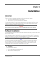
NeoFox Phase Fluorometer Installation and Operation Manual For Products: NeoFox-GT and NeoFox Sport Document: 013-20000-009-02-201510 AMERICAS & WORLD HEADQUARTERS Phone: +1 727-733-2447 Fax: +1 727-733-3962 Sales: Orders: Support: [email protected] [email protected] [email protected] Ocean Optics, Inc. 830 Douglas Ave. Dunedin, FL 34698 USA Manufacturing & Logistics 4301 Metric Dr. Winter Park, FL 32792 USA EUROPE, MIDDLE EAST & AFRICA Sales & Support Geograaf 24 6921 EW Duiven The Netherlands Phone: +31 26-319-0500 Fax: +31 26-319-0505 Email: [email protected] Germany : +49 711-341696-0 UK : +44 1865-811118 France : +33 442-386-588 Manufacturing & Logistics Maybachstrasse 11 73760 Ostfildern Germany ASIA Phone: +86 21-6295-6600 Fax: +86 21-6295-6708 Email: [email protected] Japan & Korea: +82 10-8514-3797 Ocean Optics Asia 666 Gubei Road Kirin Tower Suite 601B Changning District Shanghai PRC, 200336 www.oceanoptics.com Copyright © 2010 Ocean Optics, Inc. All rights reserved. Trademarks All trademarks within are the property of their respective owners. Limit of Liability Every effort has been made to make this manual as complete and as accurate as possible, but no warranty or fitness is implied. The information provided is on an “as is” basis. Ocean Optics, Inc. shall have neither liability nor responsibility to any person or entity with respect to any loss or damages arising from the information contained in this manual. Important Safety Notices WARNINGS 1. Intense UV radiation is emitted from the NeoFox LED. Do not look directly at the LED output with the naked eye once the SMA cap is removed. To verify there is power to the instrument, place a white piece of paper in front of LED 1. 2. Do not open the instrument case. High voltage is present. There are no serviceable parts inside. Return the instrument to the factory for service. 013-20000-009-02-201510 i Table of Contents About This Manual......................................................................................................... v Document Purpose and Intended Audience .............................................................................. v What’s New in this Document ................................................................................................... v Document Summary .................................................................................................................. v Product-Related Documentation ............................................................................................... v Safety and Compliance.................................................................................................. vi Chapter 1: Introduction ..................................................................... 1 NeoFox System Overview ............................................................................................. 1 NeoFox ...................................................................................................................................... 1 NeoFox Sport ............................................................................................................................ 2 Features..................................................................................................................................... 2 Oxygen Sensor Probes.................................................................................................. 2 Software ........................................................................................................................ 3 Applications ................................................................................................................... 3 Shipment Components .................................................................................................. 3 NeoFox ...................................................................................................................................... 3 NeoFox Sport ............................................................................................................................ 4 Additional Recommended Equipment ............................................................................ 4 Chapter 2: Installation ....................................................................... 5 Overview ....................................................................................................................... 5 Software Installation ...................................................................................................... 5 Hardware Installation ..................................................................................................... 8 Installing NeoFox Hardware Drivers .............................................................................. 10 Installing Hardware Drivers Using Windows Vista .................................................................... 10 Installing Hardware Drivers Using Windows XP........................................................................ 12 Chapter 3: Using NeoFox with NeoFox Viewer Software ................ 15 Overview ....................................................................................................................... 15 Entering a New Event .................................................................................................... 16 Data Logging ................................................................................................................. 16 Advanced Settings ..................................................................................................................... 17 Setup ......................................................................................................................................... 18 Status......................................................................................................................................... 19 013-20000-009-02-201510 ii Table of Contents Advanced Status ....................................................................................................................... 20 Advanced Settings ..................................................................................................................... 20 Sensor Type Selection................................................................................................... 22 APD Voltage .................................................................................................................. 22 Calibrating the Probe ..................................................................................................... 23 Multipoint Calibration ................................................................................................................. 23 Two-Point Calibration ................................................................................................................ 25 Saved Settings .............................................................................................................. 28 Saving Data ................................................................................................................... 30 NeoFox Communication Interfaces ................................................................................ 31 Saving/Restoring Chart Layouts .................................................................................... 31 Saving Settings .......................................................................................................................... 31 Resetting Saved Settings .......................................................................................................... 32 Chapter 4: Using NeoFox Sport ........................................................ 33 Overview ....................................................................................................................... 33 NeoFox Sport Features ................................................................................................. 33 NeoFox Sport Menu ...................................................................................................... 34 Setting Up the NeoFox Sport ......................................................................................... 36 Data Logging / Saving Data ........................................................................................... 37 Logging Data ............................................................................................................................. 37 Viewing the Data Log File Name ............................................................................................... 38 Setting the Data Logging Interval .............................................................................................. 38 Data Log File Format ................................................................................................................. 38 NeoFox Sport Saved Settings........................................................................................ 39 Low Battery Detector ..................................................................................................... 39 Appendix A: Specifications............................................................... 41 Appendix B: Maintenance ................................................................. 43 Updating Firmware ........................................................................................................ 43 Updating Software ......................................................................................................... 43 Troubleshooting ............................................................................................................. 43 Appendix C: Analog Output .............................................................. 47 Analog Output Connector .............................................................................................. 47 Configuring Analog Voltage Output Channel with NeoFox Viewer ........................................... 47 Configuring the Analog Current Output Channel with NeoFox Viewer ..................................... 48 Selecting a Data Source ............................................................................................................ 49 Selecting a Data Range ............................................................................................................. 50 Saving the Analog Output Settings ........................................................................................... 51 013-20000-009-02-201510 iii Table of Contents Analog Output Pinouts ................................................................................................... 51 Analog Output Parameters List ...................................................................................... 51 Analog Output Specifications ......................................................................................... 52 Interfacing to the 4-20mA Output ................................................................................... 52 4-20 mA Loop Voltage Supply ....................................................................................... 53 4-20 mA Isolation........................................................................................................... 54 Resistor / Volt Meter ...................................................................................................... 54 Appendix D: Calculating Drift Per Sensor........................................ 57 Index ................................................................................................... 59 iv 013-20000-009-02-201510 About This Manual Document Purpose and Intended Audience This document provides the users of the NeoFox and NeoFox Sport with instructions for setting up, calibrating and performing experiments with their equipment. What’s New in this Document This version of the NeoFox Installation and Operation Manual updates the operation instructions. Document Summary Chapter Description Chapter 1: Introduction Contains descriptive information about the NeoFox. It also provides a list of system requirements, interface options, and shipment components. Chapter 2: Installation Provides installation instructions. Chapter 3: Using NeoFox Contains steps to operate NeoFox Viewer software with the NeoFox hardware. Also contains steps for restoring screen defaults. Chapter 4: Using NeoFox Sport Contains the menu structure and operational information for the NeoFox Sport. Appendix A: Specifications Lists NeoFox specifications. Appendix B: Maintenance Contains information for updating firmware and software and a troubleshooting table. Appendix C: Analog Output Provides information about NeoFox’s analog output connector. Product-Related Documentation You can access documentation for Ocean Optics products by visiting our website at http://www.oceanoptics.com. Select Support→ Technical Documents, then choose the appropriate document from the available drop-down lists. Jaz Installation and Operation Manual NeoFox Calibration Engineering Note 013-20000-009-02-201510 v About This Manual NeoFox Communication Interfaces Engineering Note Safety and Compliance This equipment has been tested and found to comply with the limits for a Class A digital device, pursuant to Part 15 of the FCC Rules. These limits are designed to provide reasonable protection against harmful interference when the equipment is operated in a commercial environment. This equipment generates, uses, and can radiate radio frequency energy and, if not installed and used in accordance with the instruction manual, may cause harmful interference to radio communications. Operation of this equipment in a residential area is likely to cause harmful interference in which the user will be required to correct the interference at his own expense. WARNING: The authority to operate this equipment is conditioned by the requirement that no modifications will be made to the equipment unless the changes or modifications are expressly approved by the manufacturer. vi 013-20000-009-02-201510 Chapter 1 Introduction NeoFox System Overview The NeoFox is a device for measuring fluorescence lifetime, phase and intensity. It uses LED excitation and photodiode detection with filter-based wavelength selection for easy experimental set-up and control. Because the unit is self-contained, it is invariant to fiber bending and stray light, and has a wide dynamic range of optical intensity as well as low optical and electronic crosstalk, and low drift and phase noise. Therefore, the NeoFox is especially useful for oxygen sensing applications where stability and sensitivity to drift is important and where sample set-ups must be left undisturbed for long periods of time. NeoFox NeoFox is available as a compact, self-contained, benchtop unit. 013-20000-009-02-201510 1 1: Introduction NeoFox Sport NeoFox Sport is available as a handheld oxygensensing system with a phase fluorometer, an onboard microprocessor with OLED display and a battery module, or as part of the Jaz community of stackable, modular and autonomous component modules (limit of one sensor module per stack). Features NeoFox is a fluorescence-sensing detector for our optical sensors line and provides a viable alternative to traditional chemical sensing devices. Our optical sensors consist of transducer materials, applied to the tips of optical fibers or to substrates such as patches or cuvettes, which change optical properties in response to specific analytes in their immediate environment. Additional features that are available to NeoFox Sport users include: Battery-powered operation Real-time display of temperature and oxygen in various measurement units: Gaseous oxygen partial pressure as a percentage of 1 ATM. Gaseous oxygen partial pressure in Torr. Dissolved oxygen partial pressure in ppm (parts per million) Dissolved oxygen concentration in um/L (micromoles per liter) Data logging of temperature and oxygen readings in units listed above. In-field single point reset (also available on desktop NeoFox) Oxygen Sensor Probes The NeoFox is used with Ocean Optics’ NeoFox software and custom probes (priced separately). Ocean Optics oxygen sensor probes are low-power, portable devices that offer high sensitivity, reversibility, and stability. Their small size is useful for remote monitoring. What's more, the thin film used in the probe tips consumes no oxygen, allowing for continuous contact with the sample. Ocean Optics oxygen sensors offer other key advantages: they're ideal for viscous samples and are immune to interference caused by pH change or from changes in ionic strength, salinity, and biofouling. The NeoFox supports the following Ocean Optics sensors: 2 FOXY – Ocean Optics’ standard oxygen sensors designed for monitoring oxygen partial pressure in gas and aqueous solutions. FOXY is a fiber optic fluorescence probe with proprietary oxygensensing thin-film coating on the tip. 013-20000-009-02-201510 1: Introduction HIOXY – Designed for monitoring oxygen partial pressure in nonaqueous vapors and solutions. The sensor coating chemistry is compatible with oils, alcohols, and hydrocarbon-based vapors and liquids. FOSPOR – A new generation of highly sensitive sensor coating for monitoring traces of oxygen in gas and liquids. See http://oceanoptics.com/product-category/fibers-and-probes/ for more information on probes available from Ocean Optics. The NeoFox connects to a PC via USB connection and saves your data in an easy-to-use Microsoft Excel format. NeoFox can be configured with single-channel LED excitation and detection, and modulation frequencies to 100 kHz. The on-board pressure transducer measures atmospheric pressure. Software The NeoFox standalone module uses NeoFox Viewer software to display oxygen measurements on a connected Windows XP PC. The NeoFox Sport can also use NeoFox Viewer software when connected to a Windows XP PC, or it can be untethered from a computer and display some Oxygen measurements on its OLED screen. See Chapter 4: Using NeoFox Sport for more information on the functionality of the NeoFox Sport. Applications Typical applications include the following: Bioprocess monitoring Environmental applications (such as waste water management) Life science Modified Atmosphere Packaging (MAP) Shipment Components NeoFox The following equipment and information ships with the standalone NeoFox: NeoFox Unit 5V Power Adapter Mini USB Cable NeoFox CD This CD contains this manual and the NeoFox Viewer software. 013-20000-009-02-201510 3 1: Introduction Packing List The packing list is inside a plastic bag attached to the outside of the shipment box (the invoice arrives separately). It lists all items in the order, the shipping and billing addresses, and any items on back order. NeoFox Sport The following equipment and information ships with the NeoFox Sport: Jaz stack with the NeoFox Sport module(s) See your Jaz manual for more information about what ships with Jaz (refer to Product-Related Documentation). SD card containing the neofox.cal calibration file NeoFox CD Packing List Additional Recommended Equipment NeoFox Viewer Software Temperature Probe FOXY, HIOXY or FOSPOR Oxygen Sensor Probe RedEye® Patches (FOXY, HIOXY and FOSPOR) FOXY-CAL, HIOXY-CAL, FOSPOR-CAL This is an optional factory calibration service for environments from 0 to 80ºC. Bifurcated Fibers 21-02 SMA Splice Bushing This in-line adapter connects the probe to the fiber assembly. 4 013-20000-009-02-201510 Chapter 2 Installation Overview There are two steps to completely installing the NeoFox system onto your computer. First, you must install the NeoFox Viewer software. The second step is to properly install the NeoFox hardware. You must install the NeoFox Viewer software application prior to connecting the NeoFox unit to the computer to install the drivers required for the hardware. If you do not install the software first, the system will not properly recognize the NeoFox hardware. CAUTION Do not connect the NeoFox unit to the PC prior to installing the NeoFox Viewer software. Software Installation You can install the NeoFox Viewer software from either the CD that came with your NeoFox unit or from the Ocean Optics website. Use the following procedure to install NeoFox Viewer software on a Windows XP PC. The process on Windows Vista machines is very similar. The important thing to note is to make sure to install the driver from the specific location within the NeoFox Viewer\USB Driver directory. Note You may be prompted to install .NET runtime libraries if you do not already have them installed on your computer. You can select to install them from the Internet, or you can run the vc-redistsetup.exe program located on your NeoFox installation CD. However, this installation program will also need to connect to the Internet to download the necessary files. ► Procedure To install the NeoFox software, 1. Close all other applications running on the PC. 2. Start the software installation process. 013-20000-009-02-201510 5 2: Installation Installing from CD: a. Insert the CD containing the NeoFox Viewer software. b. Select the drive on your computer with the software CD. c. Double-click on the NeoFox-Viewer Setup.msi installer program for Windows XP or the NeoFox-Vista.msi installer for Vista computers. The installation wizard appears. Installing from the Web: d. Go to http://www.oceanoptics.com/technical/softwaredownloads.asp . e. Right-click on NeoFox Viewer Software and select Save Target As… to download the executable to your machine. f. Click Save. The installation begins. g. Click Run. The NeoFox Viewer Setup screen appears. 3. Click Next. The Select Installation Folder screen appears. The default location is C:\Program Files\Ocean Optics\NeoFox-Viewer\. 6 013-20000-009-02-201510 2: Installation 4. Click Next to select the default location, or browse to the desired location and click Next. You are now ready to install the software. 5. Click Install. The Neofox Viewer installs at the selected location. This process can take several minutes. When the software has successfully installed, the final Install Wizard screen appears. 013-20000-009-02-201510 7 2: Installation 6. Click Finish. Go to Hardware Installation. Hardware Installation WARNING Ensure that the plastic caps are covering the two SMA connectors on the front of the NeoFox unit. Intense UV radiation is emitted from the LEDS when the unit is powered-up. Do NOT look directly at the LED output with the naked eye. 8 013-20000-009-02-201510 2: Installation ► Procedure Note You must install the NeoFox Viewer operating software prior to connecting the NeoFox hardware to the computer. The NeoFox Viewer software installs the drivers required for the NeoFox hardware. See Software Installation. 1. Unpack the equipment and verify that you have all the necessary components (see Shipment Components and Additional Recommended Equipment). 2. Connect power cord from the power supply that came with your NeoFox unit from back of unit to an AC outlet. Do NOT look directly at the light being emitted with the naked eye. Caution Use only the power supply that came with your NeoFox unit. Using a different power supply could damage your equipment. Note On the NeoFox Sport hardware, there is a difference between the power connector on the DPU module and the power connector on the NeoFox module. The external power connector on the NeoFox module is the auxiliary power connector. It provides power only to the NeoFox module itself. It will not charge the battery or provide power to the DPU. Very few users will ever need to use the NeoFox module’s auxiliary power connector. 3. Connect the NeoFox unit to your computer using the USB cable. See Installing NeoFox Hardware Drivers. Note On the NeoFox Sport hardware, there is a difference between the USB connector on the DPU module and the USB connector on the NeoFox module. The USB connector on the NeoFox module is the NeoFox Sport’s primary USB connector. When the USB cable is attached to the NeoFox module and the stack power on, you can interact with the NeoFox module through the NeoFox Viewer software. The USB connector on the DPU is the unit’s auxiliary USB connector. You will not be able to interact with the device in NeoFox Viewer if you have plugged the USB cable into the DPU module. You will only want to use this USB port if you need to update the DPU firmware. 4. Connect the temperature probe (if you have one) to the rear panel of the NeoFox unit. 5. Locate the bifurcated fiber that came with the system. This optical fiber assembly has a “Y” shaped design. 6. Connect one arm (it doesn’t matter which one) of the bifurcated end of the probe fiber to LED connector and the other arm to the Detector connector on front of unit. 013-20000-009-02-201510 9 2: Installation 7. If you are using an Oxygen probe, locate the 21-02 SMA Splice Bushing that came with the probe. This item is a 0.75" screw with two female ends. Screw one end of the splice bushing into the SMA 905 connector on the end of the probe. If you are using the RedEye Patch, you don’t need the splice bushing. Installing NeoFox Hardware Drivers When you connect NeoFox to a computer for the first time using the USB cable, the hardware drivers should install automatically for Windows 7, 8, 8.1 and 10 if you installed the NeoFox Viewer software first. If you are using a Windows Vista or Windows XP computer, follow the appropriate instructions below to install the drivers. Installing Hardware Drivers Using Windows Vista The following Found New Hardware wizard appears when you first attach NeoFox to computers running the Vista operating system. 10 013-20000-009-02-201510 2: Installation ► Procedure 1. From the first Vista hardware wizard screen, select Locate and install driver software (recommended). The next hardware wizard screen appears. 2. Select Don’t search online. The next hardware wizard screen appears. 3. Select I don’t have the disc. Show me other options. The next hardware wizard screen appears. 4. Select Browse my computer for driver software (advanced). The next hardware wizard screen appears. 5. Highlight the driver_support directory (located beneath C:\Program Files\Ocean Optics\NeoFoxViewer) and click OK followed by Next. The next hardware wizard screen appears. 6. If the following screen appears, select Install this driver anyway. 7. When the hardware driver installation completes successfully, the following screen appears: 013-20000-009-02-201510 11 2: Installation Installing Hardware Drivers Using Windows XP The following Found New Hardware wizard appears when you first attach NeoFox to computers running the XP operating system. ► Procedure 1. From the first hardware wizard screen, select "No, not this time". Click Next. The next hardware wizard screen appears. 12 013-20000-009-02-201510 2: Installation 2. Select “Install the software Automatically (Recommended).” Click Next. The system installs the necessary driver software to operate your NeoFox device. The next hardware wizard screen appears. 3. When the hardware driver installation completes successfully, the following screen appears: 013-20000-009-02-201510 13 2: Installation 14 013-20000-009-02-201510 Chapter 3 Using NeoFox with NeoFox Viewer Software Overview When you first display the NeoFox Viewer software, the basic NeoFox Viewer screen appears. This screen’s controls enable you to perform the following actions: Insert comments into the exported data file using the Enter New Event textbox. See Entering a New Event for more information. Set scans to average Select the sensor type Select Automatic or Manual Gain Start/Stop Data Logging (see Data Logging) 013-20000-009-02-201510 15 3: Using NeoFox with NeoFox Viewer Software Entering a New Event The Enter New Event text box at the top of the screen enables you to insert your comments into a file containing exported data. Your comment will appear in the Events column at the far right end of each row of data. You may enter multiple comments. Each comment is time stamped with the instant you clicked on the Enter New Event field. When you create the export data file, your comment(s) will appear on the row of data that most closely corresponds to the time you created your comment. ► Procedure To enter a new comment: 1. Click the Enter New Event field at the top of the screen. 2. Enter your message into the text field. 3. Press the Enter key. Data Logging You can save a .csv file (useful for Microsoft Excel) via data logging. When you click the Start/Stop Data Logging button on the main NeoFox Viewer screen, the Data Logging Control Panel screen appears. When you click Start Logging, samples are exported from that point onward and continue until you click Stop Logging and then click Save Settings and Close Window. 16 013-20000-009-02-201510 3: Using NeoFox with NeoFox Viewer Software Note User-defined events entered in the Enter New Event field on the basic NeoFox Viewer screen are not written to the data logging export file. Field Description Start Logging Initiates data logging process. Actual data logging does not start until you click Save Settings and Close Window. Stop Logging Click this button to stop data logging. Data logging does not actually stop until you click Save Settings and Close Window. Specify Output File Click Choose to select the file to which the data will be exported. If the file already exists, you will be asked if you want to overwrite its contents. Specify Logging Interval Select how frequently you want data records to be written to the log file. Choose Columns to Export Select to export one of the following data types: Close Window Without Saving Changes Closes this window. None of the changes that you have made will take effect or be saved. Save Settings and Close Window All changes that you have made on this window are saved. If you have clicked Start Logging, data logging will start the moment you click Save Settings and Close Window. If you have clicked Stop Logging, data logging will stop the moment you click Save Settings and Close Window. All Columns: Exports all available types of data Standard: Exports a limited subset of the available data types (O 2%, Tau, temperature, pressure) Advanced Settings The NeoFox Viewer software provides a lot of information and features. However, most users will probably only use these functions: Oxygen reading: Use the pick list above the Oxygen Reading to select to display oxygen as O2%, P (torr), pO2 (torr), DO (ppm or mg/L), or DO (µmol/L). Sensor type selection: FOXY, HIOXY or FOSPOR Calibration Salinity Correction This screen is available from the View | Advanced Settings menu. 013-20000-009-02-201510 17 3: Using NeoFox with NeoFox Viewer Software NeoFox Viewer Advanced Settings Window Note If the controls on the right side of the screen seem to be disabled, stuck, or if they say Error even after clicking the Manual Gain button ( ), the problem is likely that the firmware and software versions are not compatible. You will then need to install the appropriate software version onto your computer to use NeoFox. See Software Installation and Appendix B: Maintenance for more information. The Advanced Settings window contains the following tabs (bottom right corner of screen): Setup Status Advanced Status Advanced Settings Setup Setup allows you to perform such functions as Sensor Type Selection, adjusting the APD Voltage (for firmware versions below 4.00), and Calibrating the Probe. 18 013-20000-009-02-201510 3: Using NeoFox with NeoFox Viewer Software Status Clicking on the Status tab displays the status information shown below. 013-20000-009-02-201510 19 3: Using NeoFox with NeoFox Viewer Software Advanced Status The Advanced Status tab displays the values of parameters such as Oxygen (base and converted), Tau, etc. as shown below. Advanced Settings This tab displays the advanced settings shown below for sensor waveform, decay waveform, FFT and salinity correction. 20 013-20000-009-02-201510 3: Using NeoFox with NeoFox Viewer Software Setting Salinity Correction NeoFox Viewer provides you with the capability to change the salinity correction setting from its default setting of 0. Salinity correction applies to dissolved oxygen for PPM and µM/L; it does not apply to percentage. ► Procedure To change the salinity setting: 1. Double-click on the Salinity Calibration value (default is 0). 2. Type the new salinity value. 3. Press Enter. 013-20000-009-02-201510 21 3: Using NeoFox with NeoFox Viewer Software Sensor Type Selection Before using the software, you must select the appropriate sensor type from the three buttons in the Sensor field on the right side of the screen. Choose FOXY, HIOXY, or FOSPOR. APD Voltage APD voltage is the voltage applied to the APD detector, which determines the detector’s sensitivity towards converting photons to electrical signal. This can be manually adjusted for firmware versions below 4.0 if the signal level of the sensor appears to be low. For firmware versions 4.00 or above, this parameter is set at the factory and cannot be changed. ► Procedure To manually adjust the signal level: 1. From the Basic View screen, select View | Advanced Settings to display the Advanced View screen. Make sure that the Setup tab (lower right corner) is selected. 22 013-20000-009-02-201510 3: Using NeoFox with NeoFox Viewer Software 2. Click the 3. button in the Gain field. Slide the APD Voltage selector to the desired level. 4. Click the button in the Gain field. Calibrating the Probe When you access the software for the first time, the Oxygen field will be blank. To see an oxygen value, you must first enter calibration information for the probe. This calibration information is unique for each oxygen sensor probe itself, but is independent of the NeoFox hardware unit. Therefore, a new calibration must be loaded each time a new sensor is added or before first use. You have the option of purchasing a factory calibration for your Oxygen Sensor Probe (FOXY-CAL, HIOXY-CAL, FOSPOR-CAL). If you have a factory calibration, follow the instructions for Multipoint Calibration. If you do not have a factory calibration, follow the instructions for a Two-Point Calibration. Multipoint Calibration Follow these instructions if you purchased a factory calibration file for your sensor. This file can be found on the NeoFox CD. To retrieve it, select Calibration from the Options menu. ► Procedure 1. From the Main screen, select Options | Calibration. 013-20000-009-02-201510 23 3: Using NeoFox with NeoFox Viewer Software 2. Click the Setup tab. The Setup screen appears. 3. Under Select Sensor Calibration Method, choose Multi-Point Calibration. 4. Under Select How Temperature Is Measured, choose Use NeoFox Temperature Sensor. 5. Under Enter Sensor Type And Optional Data, choose the type of sensor and add the serial number and any notes needed. Note Normalized decay time = τ0/τ. 6. Click the NeoFox CD. button, then browse to the location of the factory calibration file on the 7. Select the Multi-Point Calibration tab. The uploaded calibration table appears on the left side of the screen. The curve-fitted graphs appear on the right side of the screen. 24 013-20000-009-02-201510 3: Using NeoFox with NeoFox Viewer Software 8. Click on button on the bottom right corner of the screen. The Computed Calibration Constants table fills in on the bottom left corner of the screen. 9. Click the button to use the coefficients for oxygen calculation. A Download Confirmation screen appears. 10. Click Yes to confirm the download and continue. Two-Point Calibration If you want to do your own calibration instead of using a factory calibration, follow these Two-Point Calibration instructions. ► Procedure 1. From the Main screen, select Options | Calibration. 2. Click the Setup tab. The Setup screen appears. 013-20000-009-02-201510 25 3: Using NeoFox with NeoFox Viewer Software 3. Under Select Sensor Calibration Method, choose Two-Point Calibration. 4. Under Select How Temperature Will Be Measured, choose None (Two point calibration only). 5. Under Enter Sensor Type And Optional Data, choose the type of sensor and add the serial number and any notes needed. 6. Select the Two-Point Calibration tab. You need two known concentrations of oxygen to perform this calibration, one being the 0% oxygen concentration. 26 013-20000-009-02-201510 3: Using NeoFox with NeoFox Viewer Software 7. Expose your oxygen sensor to 0% oxygen and let the Tau value stabilize. You can observe the Tau value on the bottom of the screen to determine when it stabilizes. 8. Click on the Use Current Tau for Point #1 box once the tau value is stable. 9. Expose your oxygen sensor to the second known concentration of oxygen. You can expose the probe to ambient conditions in air, which is 20.9% oxygen. 10. Enter the known oxygen value in the O2% box for point #2. 11. Once the Tau value is stable, click on the Use Current Tau for Point #2 box. 12. Now that you have the two points of calibration, click anywhere in the graph chart displayed on this screen. The two points will appear on the graph (circled in red on the figure above), which will Compute Constants m and b. 13. To use this calibration for oxygen measurement, click the Confirmation screen appears. button. A Download 14. Click Yes to confirm the download and continue. The main NeoFox Viewer window will now display oxygen measurements. 013-20000-009-02-201510 27 3: Using NeoFox with NeoFox Viewer Software Note Normalized decay time = τ0/τ. Saved Settings The following parameters are saved onboard the NeoFox in its non-volatile memory. When the settings are saved, the saved values will be loaded when the device turns on: Measurement Parameters: 28 Duty Cycle Seconds on Duty Cycle Seconds off Number of Averages Oxygen Units Salinity Correction Factor 013-20000-009-02-201510 3: Using NeoFox with NeoFox Viewer Software Calibration Settings: Temperature Settings Temperature Source Fixed Temperature Value Calibration Method Sensor Type Two Point Calibration Settings Two Point – Tau0 Two Point – Tau1 Two Point – Oxygen 0 Two Point – Oxygen 1 Two Point – Slope Two Point – Offset Two Point – Temperature Multipoint Calibration Settings 12 Multipoint Original Calibration Coefficients : A0, A1, A2, B0, B1, B2, C0, C1, C2, T0, T1, T2 12 Single Point Adjusted Calibration Coefficients: A0, A1, A2, B0, B1, B2, C0, C1, C2, T0, T1, T2 Analog Output Settings: Analog Voltage Output Source Analog Voltage Lower Bound Analog Voltage Upper Bound Analog Current Output Source Analog Current Lower Bound Analog Current Upper bound Jaz Communication: Enable Jaz Interface Serial and USB Communication: RS232 Divisor Latch RS232 Divisor Add Value RS232 Divisor Mul Value RS232 Enable Uart Data Copy Type Uart Data copy Mode Uart Transmission Mode Uart Send Alerts 013-20000-009-02-201510 29 3: Using NeoFox with NeoFox Viewer Software Saving Data You can save your NeoFox data in either a .fxy file, which can be opened in a NeoFox Viewer window or in a .csv file, which is compatible with Microsoft Excel. NeoFox saves data to a disk file until you request it to stop or the application is shut down. Procedures for saving both types of files are described below. See Data Logging for more information on saving a .csv file. ► Procedure To save the measurement data in a .fxy file, 1. Select File | Save. A window appears displaying a file name with the date and the time the file was last saved. 2. Select the desired location to save the file. ► Procedure To save the measurement data in a .csv file, 1. Click the Start/Stop Data Logging… button from the main screen. The Data Logging Control Panel screen appears. 2. Click the Start Logging button. 3. Select the desired location to save the file. 4. Specify the logging interval. 5. Choose the data columns to export, either Standard or Extended (wide range of data). Standard (recommended setting) includes the following: 30 Time stamp (to tenth of a second) Pressure Temperature Tau 013-20000-009-02-201510 3: Using NeoFox with NeoFox Viewer Software % O2 Converted O2 6. Click Save Settings and Close Window to save the data. NeoFox Communication Interfaces You may wish to write programs to interface directly to the NeoFox without using the NeoFox Viewer. There are a number of ways to do so: Through the NeoFox DLL, through the NeoFox RS232 port (only NeoFox-GT units with an F or later in the third digit of its serial number support RS232 communications), or through custom USB drivers. See the NeoFox Communication Interfaces Engineering Note for more information (see Product-Related Documentation). Saving/Restoring Chart Layouts NeoFox Viewer allows you to save and restore the layout of the displayed charts. The following settings can be saved and then restored: X-axis duration Vertical height settings Y-axis scale settings Type(s) of data being displayed on multiple plotting areas within the chart window Saving a Chart Layout ► Procedure 1. Select View | Save Graph Layout from the menu. 2. Specify the name of the file where the settings will be saved. Restoring a Chart Layout ► Procedure 1. Select View | Restore Graph Layout from the menu. 2. Enter the name of the file containing the saved setting(s). Saving Settings ► Procedure To save these values in the NeoFox Viewer, 1. Navigate to the Advanced Settings screen. 2. Set the Flash Write parameter to Enabled. It will remain displayed as Enabled briefly before reverting to Disabled. 013-20000-009-02-201510 31 3: Using NeoFox with NeoFox Viewer Software 3. To save these settings through the NeoFox Sport, select Save Settings from the O2 Setup Menu. Note When the device saves a parameter through a flash write, it must save ALL of its savable settings at the same time. Therefore, actions which may appear to save specific settings to memory will actually save the entire set of savable parameters. Those actions include downloading calibration data, performing a single point reset, or manually prompting a flash write by setting the Flashed Write parameter to Enabled in the Advanced Settings Panel. Resetting Saved Settings You can reset the saved settings to their original state. ► Procedure 1. Open the device in the NeoFox Viewer and navigate to the Advanced Settings screen. 2. Set the value of the Flash Reset parameter to Enabled. This value may revert to disabled shortly thereafter. When the device is reset, the saved values revert to their factory settings. 3. Download your calibrations again after resetting the flash memory. Note For devices with firmware version 4.00 or above, the APD Bias Voltage (displayed as DAC-APD Gain) setting value persists through a flash reset. 32 013-20000-009-02-201510 Chapter 4 Using NeoFox Sport Overview The NeoFox Sport is a field-portable extension of the NeoFox oxygen measurement system. Users of the NeoFox Sport have the ability to make real-time measurements in the field without a computer or external power supply. To do this, the NeoFox Sport system uses the same NeoFox measurement hardware as the desktop NeoFox system, but also includes a battery (to supply power) and a data processing unit (to provide a user interface). Because the NeoFox Sport uses the same measurement hardware as the standalone NeoFox, user experience such as setup and measurement are common between both systems. Both systems can be connected to a PC via USB and controlled through the NeoFox Viewer software. In fact, the user interface for the desktop NeoFox and the NeoFox Sport are exactly the same. This chapter contains information for using NeoFox Sport without the NeoFox Viewer software. NeoFox Sport Features Additional features that are available to NeoFox Sport users include: Battery-powered operation. Real-time display of temperature and oxygen in various measurement units: Gaseous oxygen partial pressure as a percentage of 1 ATM. Gaseous oxygen partial pressure in Torr. Dissolved oxygen partial pressure in ppm (parts per million) Dissolved oxygen concentration in µm/L (micromoles per liter) Gaseous oxygen concentration as a percentage of total pressure in Mole% Atmospheric pressure from the on-board pressure sensor (in units kPa) Data logging of temperature, oxygen and pressure readings in units listed above. In-field “single point reset” (also available on desktop NeoFox) 013-20000-009-02-201510 33 4: Using NeoFox Sport NeoFox Sport Menu Menu Tree Description 34 013-20000-009-02-201510 4: Using NeoFox Sport Menu Item Description Sensor Readout Enables you to view the sensed values for Time, O2, temperature and Tau. The values displayed refresh every time a new sample is uploaded from NeoFox with the appropriate values. Prs Displays the atmospheric pressure measured by the on-board pressure sensor on the NeoFox Sport. O2 Displays the oxygen unit label and the current oxygen value. Temp (°C) Displays the algorithm temperature in degrees Celsius Tau (µs) Displays the value of tau (fluorescence lifetime) Sensor Setup Allows you set the parameters shown below. Single Pnt Reset Allows you to set the following parameter settings to be used when a single point reset is performed: Mole %: Default = 20.90%; Range = 000.00 – 100.00% Temperature: Default = algorithm temperature; Range = 000.00 – 200.00 °C SPR – Pressure (kPa): Default = On-board pressure sensor Tau: Default = current value of Tau; Range = 00.000 – 50.0000 A message displays informing you that the single point reset has completed. NOTE: NeoFox must be configured to Single Point mode through NeoFox Viewer. Data Logging Allows you to enable datalogging to an SD card, set the datalogging interval and see the filename used for the stored data. Default = current datalog interval. Range = 1000 – 99,999,999 ms Oxygen Units Enables you to set the units in which the O2 data is displayed. Choose from % PPO2%, ppm , torr and µmol/L, mole% Temperature Allows you to set the source of the temperature, either none, the sensor temperature or a fixed temperature in degrees Celsius (Default = current value of fixed temperature variable; Range = 0.0 – 200.0 °C). Pressure Allows you to set the source of the pressure: either none, the sensor pressure or a fixed pressure in kPa (Default = current value of fixed pressure variable; Range = 0 – 200 kPa) Averaging Set the running average of the measurements. Default = current value of variable. Range = 1– 300. Duty Cycle Set the duty cycle time in seconds. Range = 1 – 999. Set Off time to 0 to make it always run. Flashing On/Off Set the flashing status of the probe LED. 013-20000-009-02-201510 35 4: Using NeoFox Sport Menu Item Description Save Settings Select Accept to save your settings or Cancel to discard them. Sensor Info Displays sensor information: module ID, FPGA, controller and PCB revision level. Setting Up the NeoFox Sport Before using the NeoFox Sport in the field, you must download the appropriate sensor calibration to the NeoFox device. This must be done with your NeoFox device connected to a computer. ► Procedure 1. Connect the power supply to the DPU power jack (not the NeoFox auxiliary power jack). 2. Press the red power button ( ) to turn the device on. 3. Connect the USB cable between the USB port on the NeoFox module (not the DPU) and the computer. 4. Start the NeoFox Viewer software. See Chapter 3: Using NeoFox with NeoFox Viewer Software. 5. Perform a calibration. See Calibrating the Probe. 6. Select the sensor type as appropriate. 7. Verify that the calibration has been downloaded to memory by cycling power to the device and then taking a measurement. Note Once you are in the field, you will not be able to update this calibration. However, you will be able to do a Single Point Reset. 36 013-20000-009-02-201510 4: Using NeoFox Sport The following additional steps must be taken once after a flash reset has been performed. These steps are required to let the device know that it should communicate with the NeoFox Sport DPU. ► Procedure 1. In the NeoFox Viewer software, Select View | Advanced Settings. 2. Click on the Advanced Settings tab in the lower right-hand corner of the screen. 4. Scroll down to the Enable Jaz Interface parameter and set it to Enabled. 5. Set the Flash Write parameter to Enabled. It will remain displayed as Enabled briefly before reverting to Disabled. Data Logging / Saving Data NeoFox Sport provides you with the following functionality for logging/saving data: Log data to an SD card View the file name of the data log Set the data logging interval Logging Data The NeoFox Sport allows you to log data to an SD card via the Oxygen Sensor | Sensor Setup | Data Logging menu. When you select Turn datalog on from this menu, a log file is created on the SD card 013-20000-009-02-201510 37 4: Using NeoFox Sport and NeoFox Sport begins logging data automatically. The name of this log file is automatically generated when the data log begins in the format nf_xxx.tsv, where xxx is a 3-digit number for a filename that does not already exist in the NeoFox directory. When you select Oxygen Sensor | Sensor Setup | Data Logging | Turn data log off, then the file will be closed. A new file is created the next time you select Turn data log on. Viewing the Data Log File Name You cannot set the file name, but you can view the name of the current log file by selecting Oxygen Sensor | Sensor Setup | Data Logging | Data log filename. Setting the Data Logging Interval You can also set the data logging interval via the Oxygen Sensor | Sensor Setup | Data Logging | Data log interval menu selection. This can be used to reduce the size of the log file. The minimum data log interval is 1 second. Data Log File Format The datalog file is formatted as a tab separated value file. This file can be easily imported into Microsoft Excel or comparable spreadsheet programs. A single sample in the data log is formatted as follows. millisecond count <tab> upload date <tab> upload time <tab> oxygen <tab> oxygen unit label <tab> algorithm temperature <tab> sensor temperature <tab> tau <tab> algorithm pressure <tab> sensor pressure Where: Millisecond Count = The millisecond counter of the NeoFox device at the time of the actual sample. Because this value is stored at the actual sampling time, this value is a more reliable timing metric than the “upload date” and “upload time” fields. Upload Date / Upload Time = These fields represent the date and time that the sample was uploaded to the DPU. Oxygen = The oxygen measurement (in whatever units are currently selected). Oxygen Unit Label = The oxygen unit label; either “ppm”, “%”, “Torr”, or “um/L” Algorithm Temperature = The temperature that was used to perform the conversion from Tau to Oxygen. If the NeoFox’s temperature source parameter is set to: Sensor temp, then this is the sensor temperature. Fixed temp, then this is the fixed temperature value. None, then this is 200. Sensor Temperature = The sensor temperature (in degrees C). Tau = The tau value (in microseconds). Algorithm Pressure = The temperature that was used to perform the conversion from partial pressure of Oxygen to concentration or mole%. If the NeoFox’s pressure source parameter is set to: 38 013-20000-009-02-201510 4: Using NeoFox Sport Sensor Pressure, then this is the sensor pressure. Fixed Pressure, then this is the fixed pressure value. None, then this is 101 – 325. Sensor Pressure = The pressure (in kPa). NeoFox Sport Saved Settings Most of the parameters that can be set through the NeoFox Sport’s user menus can be saved to the NeoFox Sport module’s flash memory, which allows those settings to be restored the next time that the device is powered on. See Saved Settings for a list of settings that can be saved. To save the flash write settings, navigate to the Sensor Setup | Save Settings menu. Note that this saves ALL of the savable parameters in their current state. Also, performing a Single Point Reset through the DPU menu may result in all of the savable parameters being overwritten. Low Battery Detector The NeoFox Sport contains a low battery detector that prevents inaccurate readings in low battery conditions. When the device detects that battery conditions are too low for reliable operation, its tau and oxygen measurements will be set to 0 or -1. NeoFox disables its measurements shortly before the device itself turns off. 013-20000-009-02-201510 39 4: Using NeoFox Sport 40 013-20000-009-02-201510 Appendix A Specifications Specification Value Parameters Measured Gasseous oxygen partial pressure, dissolved oxygen concentration, temperature, pressure (via onboard pressure transducer) Control Software Windows 2000/XP/Vista (32 and 64-bit) and Windows 7 (32-bit) control software with data logging capability; controls include: modulation frequency, data rate, signal averaging, APD gain, analog gain, LED intensity Sampling Rate Acquires data samples every 0.1 second NOTE: This is not the response speed of the probe, just the rate at which the probe is digitally sampled Thermistor Probes Closed-end stainless steel tube with thermistor sensor mounted in tip; liquid immersible rugged design; 1/8” NPT fitting; temperature range 0 to 75 °C Pressure Measurement On-board pressure transducer monitors atmospheric pressure Input Power Approximately 2.5W @ 5V Communications USB, 0-5V analog output; 4-20mA analog output. RS232 is available on the NeoFox GT model with an F or greater in the third digit of its serial number. NeoFox Sport Upload Interval The NeoFox Sport uploads data from the NeoFox module at least once per second in the Sport configuration. Alternate configurations may have lower data rates. Battery Life In the NeoFox Sport configuration, a fully charged, gently used battery will last for approximately three hours. 013-20000-009-02-201510 41 A: Specifications 42 013-20000-009-02-201510 Appendix B Maintenance Updating Firmware Do not unplug the device while the firmware is updating. Caution Do not download a firmware version that predates the version you received with your NeoFox unit. ► Procedure 1. Download the new NeoFox firmware image from www.oceanoptics.com/technical/softwaredownloads.asp 2. Run Neofox Viewer and select Options|Firmware Update. 3. In the firmware update dialog, select Download, then choose the file that you just downloaded. Updating Software You can overwrite the previous installation. ► Procedure 1. Download the installer for the latest version of the Neofox Viewer from the Ocean Optics Software Downloads page: www.oceanoptics.com/technical/softwaredownloads.asp 2. Unzip the directory and then run the “Setup.msi” installer wizard. Troubleshooting Problem Possible Cause Suggested Solution Clicking Download during a Two-Point Calibration does not change the measured values of oxygen. The Two-Point Calibration was not performed correctly. Follow the Two-Point Calibration instructions in this manual exactly as written. 013-20000-009-02-201510 After scanning the tau values a single click on the graph area was not performed. 43 B: Maintenance Problem Possible Cause Suggested Solution At startup, the device’s controls appear disabled, no values display, or the device shows other signs of not uploading data. The NeoFox drivers and firmware versions are incompatible. Update the NeoFox firmware and NeoFox Viewer software. See Updating Software for more information. During hardware installation, the Found New Hardware Wizard” can’t find the driver or .sys file for the NeoFox. The NeoFox directory isn’t included in search. When prompted, choose to install from a specific location, then include the NeoFox installation directory in your search. This directory is located at “C:\Program Files\Ocean Optics\Neofox Viewer” by default. The drivers can be found in the USB Drivers directory located here. After running a VI that calls the Neofox DLL, LabView crashes when that VI is closed. The VI passes a function in the library an uninitialized string. The library functions generally assume that any strings passed are already initialized. Therefore, be sure to pass only initialized strings. Better error handling for this error was added in DLL version 1.89, but you should still use this convention to avoid unnecessary complications. After setting the display units to anything other than ppm, the display will not return to percent oxygen. Previous software version. This problem was resolved in version 1.92 of the Neofox Viewer. Contact Ocean Optics if you see this error in a more recent software version. Previously, this problem was solved by reinstalling the NeoFox Viewer software. Percent oxygen is above 100 or below 0. Sensor probe has been calibrated incorrectly. Recalibrate the sensor probe. A fatal error or critical error warning message appears at startup and prompts to continue or exit the application. After continuing, the FFT view does not seem to work. This problem seems to occur when the application starts with the FFT View Window active. Select Continue, then select the waveform or decay form view. Close the application and then restart. The problem should not occur again. If the problem persists, reinstall the NeoFox Viewer software. 44 013-20000-009-02-201510 B: Maintenance Problem Possible Cause Suggested Solution The HIOXY automatic frequency setting defaults to 45 KHz instead of 100 KHz. In Firmware Releases 2.03 and greater, the HIOXY probe’s automatic frequency setting has been changed from 100 KHz to 45 KHz. Using HIOXY probes calibrated at 100 KHz will produce incorrect results. Using older NeoFox units with new calibrations will also produce incorrect results. If your HIOXY probe was calibrated before 01 SEPT 2009, return it to Ocean Optics for a full recalibration at 45 KHz. Or, you can use firmware version 2.02 available from Ocean Optics. Or, you can enter the frequency setting manually, although this is not recommended. The temperature probe reading appears erratic or is drastically incorrect. Known issue with units manufactured prior to August 2009. Contact Ocean Optics Technical Support. The waveform windows or settings / status windows are displayed as popups instead of being docked on the side of the Main window N/A All utility windows can be docked or undocked by double-clicking the title bar of the utility window. HIOXY calibrations performed prior to 31 AUG 2009 yield incorrect results on NeoFox devices with updated firmware. 013-20000-009-02-201510 45 B: Maintenance 46 013-20000-009-02-201510 Appendix C Analog Output Analog Output Connector The Analog Output connector is located on the rear panel of the NeoFox unit. There are two user programmable analog outputs available on the NeoFox as follows: 4-20 mA current source 0-5V voltage source Analog threshold settings can be saved by the user to allow a NeoFox unit to operate in a stand alone mode, outputting analog signals without input from a computer. Configuring Analog Voltage Output Channel with NeoFox Viewer ► Procedure 1. Select the Advanced Settings tab on the Advanced View screen to view the advanced settings. 013-20000-009-02-201510 47 C: Analog Output 2. In the Advanced Settings tab, select an appropriate data source from the dropdown box located to the right of the “Voltage Output Source” setting. For more info on valid sources, please see Selecting a Data Source. 3. Select a valid lower bound for your represented data range by typing a number into the box located to the right of the “Analog Voltage Lower Bound” setting. In some versions of the Viewer software, this setting may be called “Voltage Limit Minimum”. For more information on selecting a lower bound for your voltage, see Selecting a Data Range. 4. Select a valid upper bound for your represented data range by typing a number into the box located to the right of the “Analog Voltage Upper Bound” setting. In some versions of the Viewer software, this setting may be called “Voltage Limit Maximum”. For more information on selecting an upper bound for your voltage, see Selecting a Data Range. You can save your settings by enabling the “Flash Write” setting momentarily. Configuring the Analog Current Output Channel with NeoFox Viewer ► Procedure 1. Select the Advanced Settings tab on the Advanced View screen to view the advanced settings. 48 013-20000-009-02-201510 C: Analog Output 2. Select an appropriate data source from the dropdown box located to the right of the Current Output Source setting. For more info on valid sources, see Selecting a Data Source. 3. Select a valid lower bound for your represented data range by typing a number into the box located to the right of the “Analog Current Lower Bound” setting. In some versions of the Viewer software, this setting may be called “Current Limit Minimum”. For more information on selecting a lower bound for your voltage, see Selecting a Data Range. 4. Select a valid upper bound for your represented data range by typing a number into the box located to the right of the “Analog Current Upper Bound” setting. In some versions of the Viewer software, this setting may be called “Current Limit Maximum”. For more information on selecting a upper bound for your voltage, see Selecting a Data Range. You can save your settings by enabling the Flash Write setting momentarily. Selecting a Data Source There are six potential data sources that can be driven by the NeoFox. The pressure mode is not currently supported as an analog data source. 013-20000-009-02-201510 49 C: Analog Output Mode Meaning 0 Off This mode does not actually turn the current source off. Instead it sets the current source to 4 mA and the voltage source to 0 V. It does not reduce the unit’s power draw. 1 Oxygen This is the standard percent oxygen mode. The data source will be percent oxygen, not a converted unit such as ppm or torr. See Mode 5 for more information on these alternate units. 2 Temperature Temperature (in degrees Celsius) 3 Pressure Not yet supported 4 Tau In microseconds 5 Alternate O2 Units In this mode, the dimensionless value of the alternate O2 value is compared with the lower and upper bound parameters. Selecting a Data Range The data ranges of the analog outputs are fully adjustable through the lower bound and upper bound settings in NeoFox Viewer. These settings are simply unitless values that are compared to the unitless value of the data source. Analog Voltage Boundaries The analog voltage lower bound represents the value of the data source that corresponds to a 0 volt analog output. The analog voltage upper bound represents the value of the data source that corresponds to a 5 volt analog output. Intermediate values are linearly scaled across this region to produce the appropriate output. Values of the data source that fall outside this region result in output voltages that are either 0 volts or 5 volts depending on whether the value of the data source exceeds the upper bound (resulting in 5 V) or falls short of the lower bound (resulting in 0V). Analog Current Boundaries The analog current lower bound represents the value of the data source that corresponds to a 4 mA analog output. The analog current upper bound represents the value of the data source that corresponds to a 20 mA analog current output. Intermediate values are linearly scaled across this region to produce the appropriate output. Values of the data source that fall outside this region result in output currents that are either 4mA or 20 mA depending on whether the value of the data source exceeds the upper bound (resulting in 20 mA) or falls short of the lower bound (resulting in 4 mA). 50 013-20000-009-02-201510 C: Analog Output Analog Data Range Example As an example, consider the following. A user who is interested in using the analog voltage output to monitor oxygen in the range from 4.5 ppm to 7 ppm would select the following settings. The result would be that any ppm values below 4.5 ppm would result in an output of 0 volts and any values above 7 ppm would result in 5 volts. In this case, 6.3 ppm would produce an analog voltage output of [(6.3 - 4.5) / (7 4.5)] * 5 = 3.6 volts. Analog Voltage Source: 5 – Alternate O2 Units Analog Voltage Lower Bound: 4.5 Analog Voltage Upper Bound: 7.00 (Oxygen Units) – “DO – ppm – Water”. (Selection of ppm as alternate O2 units) Saving the Analog Output Settings To save the analog output settings, open the “Advanced Settings” control panel and then select “Enabled” from the dropdown box located to the right of the “Flash Write” setting. This box will momentarily continue to display “enabled”, but will switch back to “disabled” when the unit has processed the command. Analog Output Pinouts Caution Be careful when wiring. Incorrect wiring could cause permanent damage to the unit. 1 = RS232 Rx 2 = 0-5V – V+ 3 = Current 4-20 - V- (Iout) 4 = Current 4-20 - V+ 5 = RS232 Tx 6 = 0-5V / RS232 GND View of Connector on Back of NeoFox Unit This is the view looking at the connector on the back of the NeoFox, with power plug on the right and the USB plug on the left. The connector is a standard PS-2 connector. Analog Output Parameters List NeoFox Viewer Parameter Potential Values Voltage Output Source 0 – Disable analog output 1 – Oxygen 2 – Temperature (not supported) 3 – Pressure (not supported) 4 – Tau 013-20000-009-02-201510 51 C: Analog Output NeoFox Viewer Parameter Potential Values 2 5 – Alternate O Units 0 – Disable analog output Current Output Source 1 – Oxygen 2 – Temperature (not supported) 3 – Pressure (not supported) 4 – Tau 2 5 – Alternate O Units Analog Voltage Lower Bound (or Voltage Limit Minimum) <floating point value> - This floating point value represents the “lower bound” of the represented range of the input data. Must be < UBOUND and ≥ 0. Analog Voltage Upper Bound (or Voltage Limit Maximum) <floating point value> - This floating point value represents the “upper bound” of the represented range of the input data. Must be > LBOUND. Analog Current Lower Bound (or Current Limit Minimum) <floating point value> - This floating point value represents the “lower bound” of the represented range of the input data. Must be < UBOUND and ≥ 0. Analog Current Upper Bound (or Current Limit Maximum) <floating point value> - This floating point value represents the “upper bound” of the represented range of the input data. Must be > L Analog Output Specifications Name Min Typ Max Conditions 4-20 mA Loop Voltage 11 V -- 24V RLoop = 2 Ω 4-20 mA Output Accuracy -- < 160 μA -- 25°C, VLoop = 12V, RLoop = 2 Ω 0-5V Output Accuracy -- < 50mV -- 25°C 0-5V Output Resistance -- -- 250 Ω -- Interfacing to the 4-20mA Output The NeoFox includes a non-isolated 4-20 mA current sink that can be used to transmit oxygen, temperature, or tau data. It is extremely important that you set up the interface for this output correctly, or else irreparable damage to the NeoFox unit can occur. 52 013-20000-009-02-201510 C: Analog Output The figure below shows a complete 4-20 mA loop and its 3 main components: the NeoFox unit, an ammeter, and a voltage supply. In the diagram, the NeoFox unit is shown on the left and the customer’s interface circuitry (voltage supply and ammeter) is on the right. Although they are drawn close together, the NeoFox unit and the customer’s interface circuitry may be physically located far apart, connected by a 2-wire cable. PIN 4 Loop Voltage Supply Neofox Unit Ammeter A PIN 3 Typical 4-20 mA Interface 4-20 mA Loop Voltage Supply As a simple current sink, NeoFox does not provide its own power for the current loop. The user must provide an isolated power supply between 11 V and 30 V (measured at the input to the NeoFox unit) to power the loop. This power supply must be completely separate from the NeoFox and its power supply; the grounds of the Neofox and the supply cannot be connected together. Most customers will use separate AC adapters to power their NeoFox unit and their interface circuitry. Usually this will result in the two circuits floating with respect to each other so that the circuit will work properly. However, it is important to note that NeoFox has a grounded metal case that is connected to its circuit ground and its USB shell. Hence, customers who connect the NeoFox’s case ground to their interface circuit’s case ground will find that the measurements are not correct. Some common situations that could lead to unintended ground connections are the following: Mounting both devices on a common metal surface (such as a DIN rail) Connecting both devices to a single computer or USB hub Using the same measurement device to measure the 0-5V output and the 4-20mA output. (The 05V output is referenced to the NeoFox circuit ground.) Using the same measurement device to communicate with NeoFox via RS232 and to measure the output of the 4-20 mA output. (RS232 is only available in NeoFox GT models with an F or greater in the third digit of its serial number, which are available by request). 013-20000-009-02-201510 53 C: Analog Output Users should be aware of any possible connections between NeoFox and their interface circuits when setting up their hardware. 4-20 mA Isolation Some users (especially those in industrial settings) may need to use an isolated 4-20 mA loop. Unfortunately, the current sink on the NeoFox unit is not isolated and is not suitable for use in environments which may cause the loop voltage to exceed 30V. However, there are a number of thirdparty products available that can convert the output of the NeoFox into an isolated 4-20 mA loop transmitter. Some suitable products include: LPI-1 Manufacturer: A Pi (http://www.api-usa.com) Suggested Vendor: Mod-tronic. (http://www.mod-tronic.com) Part Number: LPI-1 931S-A1A1N-IP1 Manufacturer: Rockwell Automation Suggested Vendor: Varies by geographic region Part Number: 931S-A1A1N-IP1 931S-C1A2D-OP* Manufacturer: Rockwell Automation Suggested Vendor: Varies by geographic region Part Number: 931S-C1A2D-OP *This part can be used to convert the 0-5V output of the NeoFox into a 4-20mA signal. Resistor / Volt Meter If an ammeter is not available, as is the case with many data acquisition systems, a voltmeter can be used instead (see following figure). To use a voltage measurement system, users should select a lowimpedance resistor and a high-impedance voltage measurement instrument. Be aware that there will be a voltage drop across the resistor that “substracts” from the loop voltage supply. The voltage drop can be calculated as resistance times current. For example, a 100 Ohm resistor at 20 mA would have a 2 volt drop across it. If the power supply was 12 V, then the loop voltage would actually measure under 10V and the system would be outside of specification (11V is the minimum specified loop voltage). It is important to select a resistor that will not “subtract” too much from the loop voltage. 54 013-20000-009-02-201510 C: Analog Output 013-20000-009-02-201510 55 C: Analog Output 56 013-20000-009-02-201510 Appendix D Calculating Drift Per Sensor Drift differs depending on the sensor formulation (FOXY, FOSPOR or HIOXY). See the table and example below. Stability (Continuous LED): Lifetime Stability (Tau): Oxygen Stability %: FOXY Formulation FOSPOR Formulation HIOXY Formulation 0.0006 usec/ HR 0.003 usec/ HR 0.0002 usec/HR 0.01% HR 0.005% HR 0.007% HR Example: Calculate drift for a FOXY sensor probe while measuring a sample every 2.5 hours for 100 hours with the LED being lit for 1 minute: New drift = reported drift * duty cycle on / duty cycle off New drift = 0.01%/hr * (1 min / (2.5 hr*60 min/hr)) so as to cancel out the dimensions New drift = 0.01%/hr *(1 min/150 min) New drift = 0.01%/hr * (.0066) New drift = 0.000066 %/ hr 2.5 * 60 converts hours into minutes, To run the experiment for 100 hours: New drift = 0.000066%/hr * 100 hrs New drift = 0.006% 013-20000-009-02-201510 57 D: Calculating Drift Per Sensor 58 013-20000-009-02-201510 Index A advanced settings, 17 Advanced Status tab, 20 analog current boundaries, 50 analog data range selection, 51 analog output, 47 connector, 47 parameters, 51 pinouts, 51 saving settings, 51 specifications, 52 Analog Output configuring current output channel, 48 configuring voltage output channel, 47 analog voltage boundaries, 50 APD voltage, 22 applications, 3 data range selecting, 50 data source selecting, 49 document audience, iv purpose, iv summary, iv E enter new event, 15 Enter New Event field, 16 equipment included, 3 recommended, 4 event entering new, 16 F B battery detector, 39 C calibration, 4 multipoint, 23 probe, 23 two-point, 25 chart layout restore, 31 save, 31 Communication Interfaces, 31 D data saving, 30 data log file format, 38 data logging, 16 NeoFox Sport, 37 013-20000-009-02-201510 features, 2 NeoFox Sport, 33 fiber, 4 firmware updating, 43 FOSPOR, 3 FOXY, 2 H hardware, 8 hardware drivers installation, 10 Windows Vista, 10 Windows XP, 12 HIOXY, 3 I Install from CD, 6 59 Index from Web, 6 installation hardware, 8 hardware drivers, 10 software, 5 isolation 4-20 mA loop, 54 L log, 16 loop voltage supply, 53 M menu NeoFox Sport, 34 menu description NeoFox Sport, 34 N NeoFox overview, 1 NeoFox Sport, 33 data logging, 37 features, 33 menu, 34 menu description, 34 saved settings, 39 setup, 36 NeoFox Viewer, 3, 17 new event entering, 16 O R recommended equipment, 4 RedEye, 4 restore chart layout, 31 S safety warnings, i salinity correction, 21 save chart layout, 31 saved settings, 28 NeoFox Sport, 39 sensor oxygen, 2, 4 select type, 22 setup NeoFox Sport, 36 Setup tab, 18 shipment components, 3 software, 3, 5, 17 NeoFox Viewer, 3 updating, 43 Software and Resources Library CD, 4 specifications, 41 Status tab, 19 T tab Advanced Status, 20 Setup, 18 Status, 19 troubleshooting, 43 U oxygen sensor probes, 2, 4 P updating, 43 probe calibrating, 23 oxygen sensor, 2, 4 temperature, 4 product-related documentation, iv 60 W what's new, iv 013-20000-009-02-201510