1
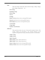
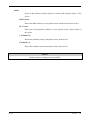
DC POWER SUPPLY / BATTERY CHARGER 12V- 24V - 48V - 110V - 220V DC USER MANUAL IMPORTANT This users manual contains setup, operation and maintenance information for Inform Battery Charger. Before starting setup and operation of the equipment, complete users manual should be read carefully. Before operation, the rectifier should be prepared by an authorized technical personnel approved by dealer. The warranty will be void, if this direction is not followed. Please contact dealers customer service, if you see any problem about any process described in this users manual. The manufacturer reserves the right to change the design of the equipment without notice. HIGH LEAKAGE CURRENT Because of the high leakage current, this equipment should be operated only after it is earthed. ELECTROMAGNETIC COMPABILITY This equipment if compatable to EMC directive 89/336/EEC and to conditions in released technical specifications. The compability remains only if related directions are followed and only if the equipment is used with accessories approved by the manufacturer. IMPORTANT In custom designs, there can be minor differences between this manual and the equipment. Ver1.2 PAGE : 1 CAUTION 1. There are no user servicable parts inside. 2. Even after the equipment is disconnected from batteries and input connections, a intervention to the interior of the equipment contains risk of electric shock. 3. Ventilation holes should be kept open and no objects should be inserted. 4. In the environment where the equipment will be operated, the temperature and humidity should be relevant. 5. Batteries should be kept away from high temperature, otherwise they can explode. 6. The equipment can not be operated in an environment having flammable and explosive devices. 7. Setup, maintenance and repair of the equipment should be performed only by trained, experienced and authorised technical personnel. 8. When working on live equipment a second person who is aware of all safety precautions and emergency actions should be present at all times. 9. It is the responsibility of each individual to be aware of national legislation, local legislation and site rules governing safety and working practices. 10. Use only good quality insulated tools and accessories, properly maintained and calibrated instruments, and suitable and adequate supports and lifting equipment. 11. Electrical energy can be supplied from the AC supply, external batteries or the external alarm or auxiliary control terminals. Ver1.2 PAGE : 2 CONTENT 1. 2. 3. 4. 5. 6. GENERAL INTRODUCTION 4 1.1 SYSTEM DESCRIPTION 4 1.2 OPERATION THEORY 4 1.3 ADVANTAGES 6 1.4 GENERAL FEATURES 7 1.5 ELECTRICAL & PHYSICAL FEATURES (1 phase input devices) 8 1.6 ELECTRICAL & PHYSICAL FEATURES (3 phase input devices) 8 SETUP 9 2.1 OPENING PACKAGE 9 2.2 CHOOSING PROPER PLACE 9 2.3 ELECTRICAL CONNECTION 9 OPERATION 10 3.1 TURNING ON THE EQUIPMENT 10 3.2 TURNING OFF THE EQUIPMENT 10 3.3 AUTOMATIC STARTUP 10 SERVICE AND MAINTENANCE 11 4.1 PERIODICAL MAINTENANCE 11 4.2 FAILURES 11 4.3 BEFORE CALLING SERVICE 11 FRONT PANEL 12 5.1 STRUCTURE OF FRONT PANEL 12 5.2 MEASUREMENTS MENU 14 5.3 CONTROL AND SETTINGS MENUS 16 OPTIONS 19 6.1 ALARM & COMMUNICATION INTERFACE BOARD (OPS-01) 19 6.2 EARTH LEAKAGE MONITORING (OPS-02) 22 6.3 DC SUPPLY & BATTERY MONITORING (OPS-03) 23 6.4 GAUGES (OPS-04) 23 6.5 LOAD VOLTAGE LIMITATION MODULE / VOLTAGE DROP (OPS-05) 24 6.6 BATTERY CHARGE TEMPERATURE COMPENSATION (OPS-06) 24 Ver1.2 PAGE : 3 1. GENERAL INTRODUCTION 1.1 SYSTEM DESCRIPTION INFORM Battery Charger is a high technology equipment, including all protection and control systems, which is designed and manufactured to convert 1 phase or 3 phase AC voltage to pure and regulated DC voltage. It provides DC power, which is especially important for industrial, telecom and military applications. When this system is used with a battery group at its output, this equipment charges battteries and acts as a uninterrupted DC power source. This equipment contains an input isolation transformer and provides full electrical isolation between input supply and DC output. This uses all advantages of DSP (Digital Signal Processor) control. It provides advanced user interface, smart diagnostics and advanced communication features. When used as battery charger, it can perform battery charge in 3 different modes: Float charge Equalizing charge Boost charge 1.2 OPERATION THEORY A rectifier programmed for automatic charge starts its charge in equalizing mode, after the AC input supply is feeded or recovered, with the assumption of that batteries are discharged when the AC input supply was not available. The equipment can switch from equalizing charge to float charge, only if the output current goes below the ¼ of the nominal current, or if the equalizing charge time expires. Rather than this, is automatic charge logic is not requested (for example operation as power supply), charge mode of the equipment can be set to one of the float or boost charges. Boost charge is only fort he initial startup of some special kinds of batteries. Boost charge is limited only by duration. Ver1.2 PAGE : 4 Automatic charge mode Float Charge Mode Boost Charge Mode Input OK. Generate equalize charge voltage Generate float charge voltage Generate boost charge voltage Output current < Inom * 0.25 ? N Equalize time expired ? Y Y Boost time exipired ? N Y N Şekil 1.1 Battery Charger Operation Theory Rectifier block diagram is shown below. LCD Panel Keypad DSP Control Measurement & Feedback Rectifier Input (AC) Input Isolation Transformer Comm. Interface (option) Measurement & Feedback Thyristor Rectifier Bridge Filtering Components Rectifier Battery Output Voltage Dropper (option) Rectifier Load Output (option) Figure 1.2 Block Diagram Ver1.2 PAGE : 5 1.3 ADVANTAGES Advantages and properties of Battery Charger are as following : 1 phase or 3 phase input (model dependent) Internal isolation transformer at input Full controlled conventional rectifier Smart control and high reliability with DSP (Digital Signal Processor) Float charge, equalizing charge and boost charge modes Automatic and manual charge modes Low output voltage ripple and high reliability 2x16 character LCD display, showing measurements, status and alarm messages Soft start Led displays for easy observation of Rectifier status. Audible alarm. Programmable current limitation Operation as voltage source or current source Calibration of measurements from front panel Language selection from front panel (English, Turkish) DC Low / High, Line Failure, Over Temperature, Short Circuit protections Ability to program all operation parameters (password protected) Programable alarm relay contact outputs (option) Possibility of monitor and control over RS232-RS485. Modbus communication (option) Earth leakage monitoring (option) Ability to monitor batteries and battery low alarm, even when the AC input fails (option) Battery temperature compensation (option) Active parallel (current sharing) operation (option) Easy observation via analog gauges (option) Ver1.2 PAGE : 6 1.4 GENERAL FEATURES INDICATIONS AND ALARMS Output Voltage Output Current Input Voltage Battery Voltage *1 Battery Current *1 Alarms DC Low DC High Input AC Low / Fail Over Temperature Current Limit Earth Leakage *1 Breaker Open *1 Memory Error Battery Too Low / Low / High *1 Fuse Failure *1 Door Open *1 Input AC OK / Fail Operation Common Alarm Digital Measurements (On LCD Display) Alarm Messages (On LCD Display) Led Indicaters COMMNICATION & REMOTE MONITORING Serial Communication RS232 / RS485 Isolated Serial Port (Modbus Communication) *1 Dry Contact Outputs 2 programable alarm contact output *1 *2 PHYSICAL FEATURES 24Vdc 48Vdc 110Vdc 220Vdc 1 phase input Dimensions *4 3 phase input 15A 30A 60A 100A 15A 30A 60A 100A 150A 200A 400A Enclosure 1 Enclosure 2 Enclosure 3 Enclosure 3 Enclosure 4 Enclosure 1 Enclosure 2 Enclosure 2 Enclosure 3 Enclosure 3 Enclosure 4 Enclosure 1 Enclosure 2 Enclosure 3 Enclosure 4 Enclosure 4 Custom Design Enclosure 1 Enclosure 2 Enclosure 3 Enclosure 4 Enclosure 4 Custom Design Custom Design -5°C / + 50°C *3 -20°C / + 50°C 0% – 90% (non condensing) 2000 meters maximum Operation Temperature Storage Temperature Relative Humidity Operation Altitude *1 Not available in stardart configuration. Only provided as option. ( See Section 6 Options) *2 4 alarm contact output is available, when RS232/RS485 communication is not used. Consult your dealer. *3 Custom solutions for very low ambient temperatures is possible, by adding termostat controlled heaters. Consult your dealer. *4 Ver1.2 Enclosure 1 : 500mm Enclosure 2 : 600mm Enclosure 3 : 750mm Enclosure 4 : 800mm / 450mm / 600mm / 700mm / 800mm / 1000mm / 1300mm / 1600mm / 1600mm PAGE : 7 1.5 ELECTRICAL & PHYSICAL FEATURES (1 phase input devices) 24V INPUT Voltage (AC) Frequency Power Factor (nominal) OUTPUT Voltage (DC) Current (Nominal) Float Charge Adjustment Range Equalizing Charge Adjustment Range Boost Charge Adjustment Range Current Limit Adjustment Range Ripple Regulation Efficiency 48V 110V 220V 220V or 230V ± 15% – 2 wire 47 Hz – 63 Hz 0.75 24V ± 1% > 87 % 48V ± 1% 110V ± 1% 15A / 30A / 60A / 75A / 100A 80% - %115% x nominal 80% - %125% x nominal 80% - %125% x nominal 25% - %100% x nominal < 1.5 % < 1.0 % > 89 % > 91 % 220V ± 1% > 93 % 1.6 ELECTRICAL & PHYSICAL FEATURES (3 phase input devices) 24V INPUT Voltage (AC) Frequency Power Factor (nominal) OUTPUT Voltage (DC) Current (Nominal) Float Charge Adjustment Range Equalizing Charge Adjustment Range Boost Charge Adjustment Range Current Limit Adjustment Range Ripple Regulation Efficiency Ver1.2 48V 110V 220V 3x380V or 3x400V ± 15 % – 4 wire 47 Hz – 63 Hz 0.80 24V ± 1% 48V ± 1% 110V ± 1% 220V ± 1% 15A / 30A / 60A / 75A / 100A / 200A / 400A 80% - 115% x nominal 80% - 125% x nominal 80% - 125% x nominal 25% - 100% x nominal < 1.5 % < 1.0 % > 87 % > 89 % > 91 % > 93 % PAGE : 8 2. SETUP 2.1 OPENING PACKAGE When the equipment is delivered to you, first to be examined is a possible damage during transport. Therefore, examine the equipment carefully. For a possible future use, save the packet and wooden pad of the rectifier after unpacking. 2.2 CHOOSING PROPER PLACE 1. For a proper ventilation, minimum distance between the rear of the rectifier and any nearby object should me minimum 20 cm. 2. Choose a place with proper temperature and humidity. 3. Do not choose any place which can cause dust and corrosion. 4. The place chosen should not have direct sunshine and shouldnt be near any heating source. 5. Operating the equipment in proper conditions will increase it lifetime. 2.3 ELECTRICAL CONNECTION All electrical connections of the rectifier exist on the back of the front door of the enclosure. All required connections to connection panel of rectifier should be made by dealers approved service personnel or by the approval of dealers service personnel. Before making the connections all power switches, isolators and circuit breakers must be in OFF position. Input AC supply should be connected to K1 switch, where DC output supply should be connected to K2 switch. In 3 phase devices, input phase sequence is not important. The equipment adaptates itself for the incoming phase sequence. Ground must be connected to the distribution panel. CAUTION Connect and control ground (PE) connection. Definitly, the equipment should’nt be operated without ground connection. NOTE In 3 phase input devices, input supply phase sequence and direction is ignorable. Ver1.2 PAGE : 9 3. OPERATION 3.1 TURNING ON THE EQUIPMENT 1. Apply 1 or 3 phase line voltage from the connected distribution panel to the rectifier, when the rectifier input breaker K1 is in OFF position. 2. Switch the input breaker K1 to ON position. Rectifier will be energized and welcome message will be shown on the front panel. 3. With a soft start , the rectifier will start to generate DC output voltage, if automatic startup is set. (See Section 5, Front Panel) 4. If manual startup is set, the rectifier will wait without generating DC. In this case, push ON buttons on the front panel. 5. From the rectifier side of the K2 output breaker, control the DC voltage, with a voltmeter. 6. Swicth the K2 output breaker to ON position. Rectifier will feed output loads. 7. Output voltage and output current can be observed via the LCD panel. 3.2 TURNING OFF THE EQUIPMENT 1. Push OFF buttons on the front panel of the rectifier. Rectifier will stop generate DC voltage. 2. Switch input breaker K1 and output breaker K2 to OFF position. 3.3 AUTOMATIC STARTUP It can be programmed, whether the rectifier starts its operation itself or not, when the AC input supply is applied. (See Section 5, Front Panel) A rectifier programmed for automatic startup will automaticly start it operation and generate DC, when the AC input supply is applied. This option is especially preferred for far installations, where user intervention is not possible. In this mode, if a trip because of an alarm condition occurs, the rectifier will atutomaticly restart and generate DC, after the alarm condition is disappered. This status can be observed by the blinking operation led. A rectifier programmed for manual startup will wait for the user to push ON buttons to start, after the AC input supply is applied. Ver1.2 PAGE : 10 4. SERVICE AND MAINTENANCE CAUTION There are no by the user servicable parts inside the equipment, therefore DO NOT OPEN THE COVER OF THE EQUIPMENT. Because of possible external battery connection and dry contact relay outputs, THERE MAY BE HIGH VOLTAGE INSIDE THE EQUIPMENT, EVEN WHEN THE RECTIFIER IS TURNED OFF. Do not permit unauthorized persons to intervent any failure, otherwise, the warranty will be void and moreover, significant injury may occour. Under normal operating conditions only preventative maintenance is required. The intervals between maintenance actions will vary according to the level of remote monitoring and the standard of cleanliness of the equipment room. 4.1 PERIODICAL MAINTENANCE The rectifier equipment is designed for a very minor maintenance requirement. Only fulfil conditions described below. 1. Clear the dust piled up in ventilation holes of the equipment. 2. You may clean the cover of the equipment with a moist cloth. 3. Record all abnormal occurrences in the service log 4. Visually check electrical connections and component for signs of overheating or corrosion. Rectify as necessary. 4.2 FAILURES As mentioned before, only authorized personnel may perform maintenance of the equipment. In any abnormal situation, before calling service, check the points described below. 4.3 BEFORE CALLING SERVICE 1. Did you read the users manual carefully and followed all directions written ? 2. Is there energy in the distribution panel, to which the rectifier is connected ? 3. Is any of the alarm leds on the front panel active ? 4. Is there a recent change in the load connected to the rectifier ? 5. Was there an overload condition ? Ver1.2 PAGE : 11 5. FRONT PANEL 5.1 STRUCTURE OF FRONT PANEL The front panel of the Rectifier contains a 2x16 character LCD (Liquid Crystal Display), control buttons and leds. Via LCD, measurements and status / alarm messages are displayed in a format, which can be easyly understood. Parts in front panel and their functions are given below. 6 1 2 3 4 5 Figure 5.1 Rectifier Front Panel 1 LCD Display Measured values, status and alarm messages of the equipment are displayed in this 2x16 character LCD display. 2 Esc Button This buton is used to get back from a submenu or to escape from adjustment without validating. 3 Up Button In menus, this button is used to see the previous item (up). In adjustments, this button is used to increase the adjusted quantity. 4 Down Button In menus, this button is used to see the next item (down). In adjustments, this button is used to decrease the adjusted quantity. 5 Enter Button This buton is used to enter a submenu or to validate a setting performed. 6 Led Displays These leds provide instantenaous information about the status of the equipment. Ver1.2 PAGE : 12 Led Color Input OK Green Operation Common Alarm Green Status Description Light Input AC is OK. No Light Input AC is low or failed. Light The equipment is generating DC. Blinking The equipment has stopped generating DC, because of an alarm condition. Because it is in Automatic Startup mode, it will restart generating DC, after the alarm condition is disappeard. No Light The equipment is not generationg DC. Light There is an alarm condition. No Light There is no alarm condition. Red In LCD display, measured values and status / alarm messages are displayed in seperate lines. Via buttons, it is possible to stroll in measurements and submenus. OU T P U T 1 1 0 . 0 V OL T A GE V F L OA T Figure 5.2 LCD Display, Measurements Menu C A L I B RA T I ON < GR OU P > Figure 5.3 LCD Display, Main Menu There is password protection to modify operation parameters. A key symbol on the most right character of the second LCD line is displayed, until correct password is entered (password disabled). An alarm condition waiting for reset (DC High and Memory Error) can be resetted by pushing to OFF buttons. Ver1.2 PAGE : 13 5.2 MEASUREMENTS MENU LCD display waits in MEASUREMENTS MENU, after the rectifier has started its operation. UP and DOWN buttons can be used to move ahead this menu. Some measured values of the rectifier are displayed on the LCD display. Item Description 1 Output Voltage [V] DC output voltage value 2 Output Current [A] DC output current value 3 Line Voltage (R) [V] Input R phase AC voltage value (True RMS) 4 Line Voltage S [V] Input S phase AC voltage value (True RMS) (Only 3 phase input devices) 5 Line Voltage T [V] Input T phase AC voltage value (True RMS) (Only 3 phase input devices) 6 Battery Voltage [V] Battery DC voltage value (Only for devices having OPS-03 option) 7 Battery Current [A] Battery DC current value (Only for devices having OPS-03 option) 3 ~ 1 2 + 6 4 ~ 5 ~ - Figure 5.4 Measured Values Alarm and warning messages are displayed timely on the LCD display. Audible alarm is also provided at the mean time. Ver1.2 PAGE : 14 Possible alarm and warning messages are listed below. Message Meaning of the message DC LOW Indicates that the rectifier output voltage is lower than the adjustable DC LOW value. System continues to operate. DC HIGH Indicates that the rectifier output voltage is higher than the adjustable DC HIGH value. In this case, the equipment will stop generating DC to prevent any damage to batteries or load. LINE FAILURE Indicates that the rectifier AC input voltage is low or failed. OVER TEMPERATURE Indicates that the thyristor bridge temperature has exceeded limits. The equipment will stop generating DC. EARTH FAULT Indicates there is a leakage current from any of the DC outputs to ground. (OPS-02) MEMORY ERROR Indicates, that the DSP control unit can not load the saved parameters properly. In this case, the system will return to factory set values. Until this alarm is resetted via the LCD panel, the equipment does not generate DC. BREAKER OPEN CURRENT LIMIT FAN FAILURE Indicates that one of the input, output or battery circuit breakers are open. (Option depending on user requirement) Indicates that the equipment decreases its output voltage to keep the output current in set current limit value. The equipment is in current limiting and in operates at constant current mode. Indicates the failure of the cooling fan. (Option depending on user requirement) BATTERY TOO LOW Indicates that the measured battery voltage is lower than the adjustable BATTERY TOO LOW value. (OPS-03) BATTERY LOW Indicates that the measured battery voltage is lower than the adjustable BATTERY LOW value. (OPS-03) BATTERY HIGH Indicates that the measured battery voltage is lower than the adjustable BATTERY HIGH value. (OPS-03) FUSE FAILURE DOOR OPEN Indicates that one or more of the semiconducter rapid fuses has blown. (Option depending on user requirement) Indicates that the enclouse door is opened. Used to inform the remote site, in case there is maintenance on the rectifier. (Option depending on user requirement) Ver1.2 PAGE : 15 5.3 CONTROL AND SETTINGS MENUS Control and Settings Menus can be reached by a push to Enter button, when the screen is in Measurements Menu. The structure and hierarchi or these menus are given below. Functional Password This item is the password required to modify other adjustable parameters. The equipment is shipped with default password 0000. New Password After the correct password is entered, the password can be modified using this item. Start Mode This setting defines whether the rectifier will start generating DC voltage itself or after an user intervention, when it is energized. Language Defines the language selection for front panel. Front panel language can be choosen as English or Turkish. Default language after factory test is English. Serial Link (Only for devices having OPS-01 option) This setting is used to select, which application will occupy the serial link of the rectifier. FreeMaster communication for factory settings or Modbus communication for user purposes can be chosen. Alarm Relays (Only for devices having OPS-01 option) This menu block is used to set up which relay or relays will be released in which alarm condition. (Only for devices having OPS-01 option) Modbus This submenu contains items to setup the Modbus communication. Comm. Mode Baud Rate Slave No Parity Permission Ver1.2 PAGE : 16 Setup This menu mainly contain items about electrical settings. (Charge voltages, alarm voltages, charge mode, …etc.) Float Voltage Equalizing Voltage Boost Voltage DC Low DC High Battery Too Low (Only for devices having OPS-03 option) Battery Low (Only for devices having OPS-03 option) Battery High (Only for devices having OPS-03 option) Current Limit Charge Mode Equalize - Boost Duration Calibration This menu block allows the user to fine tune the measured values of the rectifier, without any intervention to the electronic hardware of the equipment. Using this menu only by authorized personnel is recommended. Output Voltage Output Current Input Voltage (R) Input Voltage S (Only 3 phase input devices) Input Voltage T (Only 3 phase input devices) Battery Voltage (Only for devices having OPS-03 option) Battery Current (Only for devices having OPS-03 option) Ver1.2 PAGE : 17 About Items in this submenu shows software versions and nominal values of the device. DSP Version Shows the DSP software version placed on the control board of the device. uC Version Shows the microcontroller software version placed on the control board of the device. V Nominal (V) Shows the nominal voltage (nameplate value) of the device. I Nominal (A) Shows the nominal current (nameplate value) of the device. NOTE Default (factory setting) password is 0000. Ver1.2 PAGE : 18 6. OPTIONS 6.1 ALARM & COMMUNICATION INTERFACE BOARD (OPS-01) Alarm & Communication Interface Board provides the user RS232 / RS485 communication and dry contact outputs. A view of the Alarm & Communication Interface Board is given below. Figure 6.1 Alarm & Communication Interface Board Ver1.2 PAGE : 19 6.1.1 Dry Contact Outputs Alarm & Communication Interface Board option provides 2 dry contact outputs to the user. Dry contact outputs can be programmed by the user via the LCD panel or Modbus communication, depending on the requirement. Although the features of the model is deterministic, the following status can be programmed for the dry contact outputs: Output OK / Normal Operation Input AC Low / Fail DC Low DC High Over Temperature Memory Error Current Limit Earth Leakage (OPS-02) Battery Low (OPS-03) Battery High (OPS-03) Battery Too Low (OPS-03) Boost Charge Expired Fan Failure (Option depending on user requirement) Breaker Open (Option depending on user requirement) Fuse Failure (Option depending on user requirement) Door Open (Option depending on user requirement) Dry contacts remain energized, when the alarm condition is not occoured. When the programmed condition occours (for example, if DC High alarm is detected), dry contact is releases and switches to unenergized state. Dry contact outputs are provided to the user directly from plugin sockets placed on the Alarm & Communication Interface Board. NOTE Maximum 24Vac or 24Vdc voltage should be applied to dry contacts. Dry contacts are for signaling purposes and can carry maximum 0.5A current. Ver1.2 PAGE : 20 6.1.2 RS232 Communication This option provides Modbus communication over RS232/RS485 connection, for remote control and monitoring. charger Alarm Relay Board RS232 Figure 6.2 Rectifier / PC Connection For RS232 communication, 9 pin female DSUB connector on the Communication & Alarm Relay Board is used. Pin connections of he necessary cable for rectifier RS232 rectifier connection is given in the table below : Rectifier side cable (DSUB9 Male) Pin No Function 2 RX 3 TX 5 GND PC side cable (DSUB9 Female) Pin No Function 3 TX 2 RX 5 GND Depending on the request of the user, it is possible to provide RS485 output, by adding a RS232 / RS485 converter, on the manufacturing. NOTE RS232 / RS485 port is isolated from the rest of the rectifier. NOTE Contact your dealer for Modbus adresses. Ver1.2 PAGE : 21 6.2 EARTH LEAKAGE MONITORING (OPS-02) This option is used to detect a possible leakage current flowing from the DC source to the ground. It is especially preferred in industrial applications and power plants. + Rectifier DC Power Supply Battery Bank Load - Figure 6.3 Earth leakage condition When a current from any of the positive or negative poles of the dc power supply flows to the ground, an unbalance occours in the measurement of the DC bus voltage respect to ground. This unbalance condition is detected by the Earth Leakage Monitoring Board. DC inputs to the Earth Leakage Monitoring Board are fuse protected. - E + 1A 1A Earth leakage DC supply OK Figure 6.4 Earth Leakage Monitoring Board Ver1.2 PAGE : 22 6.3 DC SUPPLY & BATTERY MONITORING (OPS-03) This option provides, that the rectifier control system and LCD panel stil remains energized, even when the rectifier input voltage fails. Because of this option, rectifier is able to provied some alarm and warning messages and monitor the discharge status of the battery. Following measurements are possible (in addition to the standarts), when this option is used : Battery Voltage and Current Measurement Battery Voltage Alarms (Battery Too Low / Low / High) 6.4 GAUGES (OPS-04) In this option, standart (72x72mm or 96x96mm) 1.5 % accurate gauges are provided for easy observation of some operation measurements. These gauges or mounted on the front door of the enclosure. Depending on request, following values can be measured and observed : AC Input voltage (with selective switch in 3 phase input devices) DC Output Voltage DC Output Current Battery Voltage Battery Current (charge and discharge) Input Voltage Output Voltage Output Current Figure 6.5 Gauges NOTE On equipments where gauges option is applied, LCD panel and keypad is not removed and remain functional. Ver1.2 PAGE : 23 6.5 LOAD VOLTAGE LIMITATION MODULE / VOLTAGE DROP (OPS-05) This option provides seperate load and battery outputs with different voltage levels. In this option, the voltage applied to batteries on equalizing charge or boost charge is limited by diod groups as nedeed and applied to load output. This way, a high voltage to the load is prevented. 6.6 BATTERY CHARGE TEMPERATURE COMPENSATION (OPS-06) This option provides the compensation of charge voltage depending on the ambient temperature of the battery room. This kind of charge lenghtens the battery life. A temperature sensor connected to the rectifier is placed to the environment where batteries are installed. Ver1.2 PAGE : 24