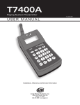
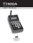
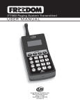
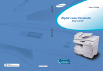
1
T7450A
Paging System Transmitter
U S E R M A N UA L
g
Lon
s
tem 6
Sys 99
ge .437.4
n
a
0
R 80
F4
F3
50A
T74
F2
F1
3
F
DE
1
C
AB
SET
I
GH
2
UP
6
R
PQ
5
O
MN
4
JKL
L
CEL NE
PHO
9XYZ
8VW
7STU
0
[
ER
PAG
TER
EN
AR
CLE
STA
FF
I n s t a l l a t i o n , Wa r r a n t y a n d S e r v i c e I n f o r m a t i o n
Long Range Systems UK Ltd | Link House | Leek Road | Milton | Stoke on Trent | Staffordshire | ST2 7AH | 01782 537000
www.lrspagers.co.uk | www.pagers.co | www.hospitalpagers.co.uk
Table Of Contents
Long Range Systems . . . . . . . . . . . . . . . . . . . . . . . . . . . . . . . . . . . . . . . . . . . . .
3
General Information . . . . . . . . . . . . . . . . . . . . . . . . . . . . . . . . . . . . . . . . . . . . . .
3
Compatible Pagers . . . . . . . . . . . . . . . . . . . . . . . . . . . . . . . . . . . . . . . . . . . . . . .
4
Installation and Setup . . . . . . . . . . . . . . . . . . . . . . . . . . . . . . . . . . . . . . . . . . . .
5
Transmitter Install . . . . . . . . . . . . . . . . . . . . . . . . . . . . . . . . . . . . . . . . . . . . . . . . . . . .
5
Keypad Description . . . . . . . . . . . . . . . . . . . . . . . . . . . . . . . . . . . . . . . . . . . . . . . . . . .
5
Initial Power Up . . . . . . . . . . . . . . . . . . . . . . . . . . . . . . . . . . . . . . . . . . . . . . . . . . . . . .
6
Operating Limitations . . . . . . . . . . . . . . . . . . . . . . . . . . . . . . . . . . . . . . . . . . . .
7
Basic Paging Operation Guide . . . . . . . . . . . . . . . . . . . . . . . . . . . . . . . . . . . . . .
7
Page Guest Pagers . . . . . . . . . . . . . . . . . . . . . . . . . . . . . . . . . . . . . . . . . . . . . . . . . . . .
7
Page Guest Alpha Coasters . . . . . . . . . . . . . . . . . . . . . . . . . . . . . . . . . . . . . . . . . . . . .
7
Page Guest Cell Phone or Pagers . . . . . . . . . . . . . . . . . . . . . . . . . . . . . . . . . . . . . . . .
7
Page Individual Staff Pagers . . . . . . . . . . . . . . . . . . . . . . . . . . . . . . . . . . . . . . . . . . . .
7
Page Staff Group . . . . . . . . . . . . . . . . . . . . . . . . . . . . . . . . . . . . . . . . . . . . . . . . . . . . .
8
All Staff Page . . . . . . . . . . . . . . . . . . . . . . . . . . . . . . . . . . . . . . . . . . . . . . . . . . . . . . . .
8
All Call Page . . . . . . . . . . . . . . . . . . . . . . . . . . . . . . . . . . . . . . . . . . . . . . . . . . . . . . . . .
8
Paging Staff Pagers from a Remote Telephone . . . . . . . . . . . . . . . . . . . . . . . . . . . .
9
Preset or Special Alpha Messages . . . . . . . . . . . . . . . . . . . . . . . . . . . . . . . . . . . . . . .
9
Special Operational Procedures . . . . . . . . . . . . . . . . . . . . . . . . . . . . . . . . . . . . .
10
Theft-Deterrent . . . . . . . . . . . . . . . . . . . . . . . . . . . . . . . . . . . . . . . . . . . . . . . . . . . . . .
10
Telephone Interface . . . . . . . . . . . . . . . . . . . . . . . . . . . . . . . . . . . . . . . . . . . . . . . . . . .
10
System Requirements
................................................
11
Telephone Dialing Properties . . . . . . . . . . . . . . . . . . . . . . . . . . . . . . . . . . . . . . . . . . .
11
DTMF Properties . . . . . . . . . . . . . . . . . . . . . . . . . . . . . . . . . . . . . . . . . . . . . . . . . . . . .
11
Setting the Telephone Dial In or Dial Out Function On or Off . . . . . . . . . . . . . . . . .
12
Locate Misplaced Pagers . . . . . . . . . . . . . . . . . . . . . . . . . . . . . . . . . . . . . . . . . . . . . . .
13
Tracking Modes . . . . . . . . . . . . . . . . . . . . . . . . . . . . . . . . . . . . . . . . . . . . . . . . . . . . . .
14
Group Paging . . . . . . . . . . . . . . . . . . . . . . . . . . . . . . . . . . . . . . . . . . . . . . . . . . . . . . . .
15
Auto Shut Off POCSAG Pagers . . . . . . . . . . . . . . . . . . . . . . . . . . . . . . . . . . . . . . . . . .
16
Feature Setup Procedures . . . . . . . . . . . . . . . . . . . . . . . . . . . . . . . . . . . . . . . . .
17
User’s Access Code . . . . . . . . . . . . . . . . . . . . . . . . . . . . . . . . . . . . . . . . . . . . . . . . . . .
17
Set Page Mode . . . . . . . . . . . . . . . . . . . . . . . . . . . . . . . . . . . . . . . . . . . . . . . . . . . . . . .
17
Set to Page Staff or Guest Pagers . . . . . . . . . . . . . . . . . . . . . . . . . . . . . . . . . . . . . . .
18
Create Alpha Messages . . . . . . . . . . . . . . . . . . . . . . . . . . . . . . . . . . . . . . . . . . . . . . . .
18
Set Alarms . . . . . . . . . . . . . . . . . . . . . . . . . . . . . . . . . . . . . . . . . . . . . . . . . . . . . . . . . .
18
Set Start of POSCAG Paging . . . . . . . . . . . . . . . . . . . . . . . . . . . . . . . . . . . . . . . . . . .
19
Enable/Disable Direct Dialing Input . . . . . . . . . . . . . . . . . . . . . . . . . . . . . . . . . . . . . .
19
Remember Telephone Numbers . . . . . . . . . . . . . . . . . . . . . . . . . . . . . . . . . . . . . . . . .
20
Dry Contact . . . . . . . . . . . . . . . . . . . . . . . . . . . . . . . . . . . . . . . . . . . . . . . . . . . . . . . . . .
20
Testing Dry Contact . . . . . . . . . . . . . . . . . . . . . . . . . . . . . . . . . . . . . . . . . . . . . . . . . . .
21
Long Range Systems
1
T7450A User Manual
Maintenance Functions . . . . . . . . . . . . . . . . . . . . . . . . . . . . . . . . . . . . . . . . . . .
22
User’s Access Code . . . . . . . . . . . . . . . . . . . . . . . . . . . . . . . . . . . . . . . . . . . . . . . . . . .
22
Set the System Time/Date . . . . . . . . . . . . . . . . . . . . . . . . . . . . . . . . . . . . . . . . . . . . .
22
Review System Status . . . . . . . . . . . . . . . . . . . . . . . . . . . . . . . . . . . . . . . . . . . . . . . . .
23
Maintenence Code . . . . . . . . . . . . . . . . . . . . . . . . . . . . . . . . . . . . . . . . . . . . . . . . . . . .
23
Time and Date Format . . . . . . . . . . . . . . . . . . . . . . . . . . . . . . . . . . . . . . . . . . . . . . . . .
23
System ID Functions . . . . . . . . . . . . . . . . . . . . . . . . . . . . . . . . . . . . . . . . . . . . . . . . . .
24
Messaging Mode . . . . . . . . . . . . . . . . . . . . . . . . . . . . . . . . . . . . . . . . . . . . . . . . . . . . .
25
Programming Pagers . . . . . . . . . . . . . . . . . . . . . . . . . . . . . . . . . . . . . . . . . . . . .
26
Individual Pagers . . . . . . . . . . . . . . . . . . . . . . . . . . . . . . . . . . . . . . . . . . . . . . . . . . . . .
26
Guest Pagers . . . . . . . . . . . . . . . . . . . . . . . . . . . . . . . . . . . . . . . . . . . . . . . . . . . . . . . .
26
Guest Alpha Coasters . . . . . . . . . . . . . . . . . . . . . . . . . . . . . . . . . . . . . . . . . . . . . . . . .
26
Staff Pagers . . . . . . . . . . . . . . . . . . . . . . . . . . . . . . . . . . . . . . . . . . . . . . . . . . . . . . . . .
27
Program Alpha Pager Group . . . . . . . . . . . . . . . . . . . . . . . . . . . . . . . . . . . . . . . . . . .
28
Alpha Encryption . . . . . . . . . . . . . . . . . . . . . . . . . . . . . . . . . . . . . . . . . . . . . . . . . . . . .
29
Additional Alpha Functions . . . . . . . . . . . . . . . . . . . . . . . . . . . . . . . . . . . . . . . . . . . . .
29
Set Pager Vibrator ON/OFF . . . . . . . . . . . . . . . . . . . . . . . . . . . . . . . . . . . . . . . . . . . . .
30
Station ID . . . . . . . . . . . . . . . . . . . . . . . . . . . . . . . . . . . . . . . . . . . . . . . . . . . . . . . . . . .
30
Adjust Transmitter Power . . . . . . . . . . . . . . . . . . . . . . . . . . . . . . . . . . . . . . . . . . . . . .
30
Set ID Span . . . . . . . . . . . . . . . . . . . . . . . . . . . . . . . . . . . . . . . . . . . . . . . . . . . . . . . . . .
31
Range Test . . . . . . . . . . . . . . . . . . . . . . . . . . . . . . . . . . . . . . . . . . . . . . . . . . . . . . . . . .
31
Repeat Delay . . . . . . . . . . . . . . . . . . . . . . . . . . . . . . . . . . . . . . . . . . . . . . . . . . . . . . . . .
31
System Specifications . . . . . . . . . . . . . . . . . . . . . . . . . . . . . . . . . . . . . . . . . . . .
32
Transmitter . . . . . . . . . . . . . . . . . . . . . . . . . . . . . . . . . . . . . . . . . . . . . . . . . . . . . . . . . .
32
Battery Powered Pagers . . . . . . . . . . . . . . . . . . . . . . . . . . . . . . . . . . . . . . . . . . . . . . .
32
Rechargeable Pagers . . . . . . . . . . . . . . . . . . . . . . . . . . . . . . . . . . . . . . . . . . . . . . . . . .
32
Troubleshooting . . . . . . . . . . . . . . . . . . . . . . . . . . . . . . . . . . . . . . . . . . . . . . . . .
33
Transmitter Functions . . . . . . . . . . . . . . . . . . . . . . . . . . . . . . . . . . . . . . . . . . . . . . . . .
33
Battery Powered Pagers . . . . . . . . . . . . . . . . . . . . . . . . . . . . . . . . . . . . . . . . . . . . . . .
33
Rechargeable Pagers . . . . . . . . . . . . . . . . . . . . . . . . . . . . . . . . . . . . . . . . . . . . . . . . . .
34
Service Questions and Answers . . . . . . . . . . . . . . . . . . . . . . . . . . . . . . . . . . . . .
34
Pager Instructions . . . . . . . . . . . . . . . . . . . . . . . . . . . . . . . . . . . . . . . . . . . . . . .
35
Using the 4-Line Alpha Numeric Pager . . . . . . . . . . . . . . . . . . . . . . . . . . . . . . . . . . .
35
Using the Star Pager . . . . . . . . . . . . . . . . . . . . . . . . . . . . . . . . . . . . . . . . . . . . . . . . . .
37
Using the SP5 1-Line Rechargeable Alpha Numeric Pagers . . . . . . . . . . . . . . . . . .
38
Using the Non-Alpha Guest Pagers . . . . . . . . . . . . . . . . . . . . . . . . . . . . . . . . . . . . . .
40
Using the Alpha Coaster Guest Pagers . . . . . . . . . . . . . . . . . . . . . . . . . . . . . . . . . . .
40
Cleaning & Charging Instructions for LRS Paging Equipment
.............
41
Warranty . . . . . . . . . . . . . . . . . . . . . . . . . . . . . . . . . . . . . . . . . . . . . . . . . . . . . . .
42
Long Range Systems
2
T7450A User Manual
Long Range Systems
Thank you for choosing Long Range Systems to provide your on-premise paging solution. We provide cutting edge products and first-rate service to satisfy your needs for years to come. Please familiarize yourself
and your staff with the contents of this instruction in order to properly operate and maintain your system.
For help operating your system or for any service problems, please call:
(800) 437-4996.
Keep this instruction in a safe place with copies available to managers and key staff.
General Information
The Trinity Paging System is used to page three types of receivers.
• On site guest pagers.
• On site staff pagers (Rechargeable and/or Battery powered)
• Patron provided telephone pagers (cell phones and wide area pagers).
On site receivers are paged directly through a radio transmitter located in the T7450A transmitter. Patron cell
phones are contacted by calling their service through a dedicated telephone line.
Additional functions available with this system are:
• Group Paging. Multiple Staff Pagers assigned to work groups can be paged at the same time.
• On site pager programming. Groups can be reconfigured and pagers renumbered as necessary
using the transmitter.
• Off site paging of on-site staff pagers through the telephone line.
Long Range Systems
3
T7450A User Manual
Compatible Pagers
Customer Pagers:
Staff Pagers:
• Coaster Call
• SP5 1-Line
Rechargeable Alpha
Numeric Pager
www.pager.net
1
.
approx
ime is
Wait T minutes
5
4
1
• Alpha Coaster
• Star Pager
2
.net
.pager 96
www
49
437.
800.
1
3
4
• RX-E 4-Line Alpha
Numeric Pager
(Battery Operated)
2
800
1
www.p .437.4996
ager.ne
t
Star
Pag
er
• AdverTeaser
(Paddle) Pager
800.437.4996
www.pager.net
4
3
www.pager.net
• Pizza Pager
• Lobster Pager
Long Range Systems
4
T7450A User Manual
Installation and Setup
Transmitter Installation
!
CAUTION:: : Do not connect any other devices to the transmitter. The transmitter requires a
separate power supply.
!
CAUTION:: Do not mount the transmitter antenna near any large metal objects.
1. Unwrap all controller components.
2. Connect the antenna (about 3" long) onto the connector on the back of the transmitter. It is best
to mount the antenna pointing straight up, perpendicular to the ground.
3. Mount the transmitter convenient to 110/220V power.
4. Plug the power supply into standard 110/220V outlet and the barrel connector end into either of
the side holes on the transmitter.
5. Connect a dedicated analog telephone line to the telephone jack on the side of the transmitter.
Note: when the power is connected and a phone line is installed the unit will check the line for acceptability. If the unit detects no line or a digital line have your phone service representative apply the correct line type.
6. If your phone line requires dialing a digit to get an outside line, be sure to set up the transmitter
this way (see Setting Telephone Dialing Properties on page 11).
7. Upon completion of setup make sure pagers are fully charged and/or have good batteries and are
powered on.
8. You should perform a range test (page 31) to see if the pagers can be paged in all waiting locations of your facility.
110 VAC ELECTRICAL SUPPLY
10 VAC POWER ADAPTER
CONDOR
(408)745-7141
CLASS 2 TRANSFORMER
INPUT: AC 12OV 60Hz 19w
OUTPUT: AC 9V 1800mA
P/N: A91A8
ANTENNA
UL
RoHS
LISTED
C
UL
MODEL: 48A -9- 1800
EIA 363 0635 S
MADE IN CHINA
12:00: 36 am
KEYPAD/TRANSMITTER
Guest
#:
----
Long Range Systems
T7450A
800.437.4996
F1
SETUP
CELL
PHONE
PAGER
1
ABC
4
JKL
F3
2
DEF
5
MNO
F4
3
GHI
6
PQR
9
STU
7
8
VW
XYZ
CLEAR
0
ENTER
[
STAFF
F2
Analog Phone Line
Keypad Description
Before using the keypad, please read the following descriptions. Note that during any setup functions that
the display changes the keys may perform different functions.
Long Range Systems
5
T7450A User Manual
Setup Key
F Keys
The Setup key enables
menus when checking or
changing the transmitter’s
programmed settings.
The F (function) keys are
the first row of keys under
the display. The F1 - F4
keys correspond to the
bottom row of text in the
keypad display window.
Mgr1, Mgr2, and Staff
keys are used to page a
manager.
Mgr1 and
Mgr2 keys can be assigned to a specific pager.
Long Range Systems
T7450A
Number Keys
800.437.4996
F1
SETUP
CELL
PHONE
Staff (Pager) Key
The Staff key is used to
temporarily change the
paging function to page
Staff pagers.
#: ---
F2
F3
1
2
ABC
DEF
5
4
JKL
MNO
F4
3
GHI
Keys 1 through 0 enter
numeric data such as the
pager number. In some
modes they will also
enter alpha data.
6
PQR
Enter Key
PAGER
STAFF
9
STU
7
8
VW
XYZ
CLEAR
0
ENTER
[
Mgr 1 and Mgr 2 Keys
12:00: 36 am
Guest
The Enter key is used to
start the paging function,
and to complete programming where required.
Clear Key
The Clear key is used to
clear the input when
paging a pager or
coaster and return to the
Guest paging display or
to restart an input when
programming.
Initial Power Up
1. When power is applied the transmitter begins initializing. During the initialization the state of the
telephone interface is shown,
2. After the transmitter initializes, enter the current time and press the <Enter> key. (NOTE: Pressing F1 (EXIT) bypasses this function and sets the time to 12:00am).
3. When the display asks for AM or PM press the F1 Key for AM or the F4 key for PM. (Note that AM
is right above the F1 key and PM is right above the F4 key). The display changes to the guest
menu with the time shown.
4. Enter the current Date and press the Enter key. The display will show to enter the date as
MM/DD/YY (month/day/year) or DD/MM/YY. (Note: Pressing F1 (EXIT) bypasses this function and
sets date to January 1st of current year, example 01/01/07.)
Long Range Systems
6
T7450A User Manual
OPERATING LIMITATIONS
Be aware of the following operational limitations when using this system.
• Guest Pager numbers 500 to 627 cannot be used, and are reserved for Cell Phone Paging, WAP
Paging, and Dry Contacts.
• When Group Paging is enabled, Staff Pagers numbered between 1 and 99 cannot be used.
Basic Paging Operation Guide
The T7450A is shipped from the manufacturer set for use in the most commonly used configuration.
Page Guest Pagers:
Enter the number assigned to the guest at handout and press Enter.
Note: be sure to put pagers back on charge when returned.
Page Guest Alpha Coasters:
1. Enter the number assigned to the guest at handout and press Enter.
2. Enter number of preset or custom message and press Enter.
Page Guest Cell Phones or Pagers: (If outgoing Telephone interconnect enabled)
Collect Guest Information
• Press Cell Phone or Pager.
• Enter the patron’s cell phone or pager service number and press Enter.
• Note the Guest Reference Number shown on the screen on the call sheet.
• Press Enter (this loads the number in the call reference).
Paging Guest:
• When the patron’s service becomes available, enter the Guest Reference Number and press Enter.
• The prerecorded message is sent to their pager or cell phone.
Page Individual Staff Pagers:
1. Press the Staff button.
2. Enter the pager number and press Enter.
3. At the Select Page Mode screen:
Long Range Systems
7
T7450A User Manual
Star Rechargeable Pagers:
• Press V1, V2, or V3 to send 1, 2, or 3 vibrations to the pager or
• Enter a MSG: 0 – 9 and press Enter.
Numeric Pagers:
• Press V1, V2, or V3 to send 1, 2, or 3 vibrations to the pager or
• Select an alpha message and press Enter (Note: a list of preset messages is shown on page 9.)
Alpha Pagers:
• Select an alpha message and press Enter (Note: a list of preset messages is shown on page 9.)
Page Staff Groups:
If Groups is enabled, Staff numbers 1 through 99 will page the group of pagers.
1. Press the Staff button.
2. Enter the group number and press Enter.
• At the Select Page Mode screen select vibration or message and press Enter (see the list of preset messages).
All Staff Page: (if all staff pagers need to be called at once)
• Press Staff.
• Press 9 1 1 then Enter.
• Enter message number code (000-999) (see Preset Messages Table below).
• Press Enter or choose F1 (V1), F2 (V2), F3 (V3) or F4 (Exit) for 1, 2, or 3 vibrations.
All Call Page: (if all guest and staff pagers need to be called at once)
For Guests:
• At “Guest #: - - -“ Screen Display, press 000 then Enter.
• At Page All? press YES (F1).
For Staff:
• Press Staff.
• At “Pager #: - - -“ Screen Display, press 000 then Enter.
• At Page All? press YES (F1).
• Enter a message 0 – 9 (for SP4) or a message number code (000-999) (see Preset Messages
Table below).
• Press Enter or choose F1 (V1), F2 (V2), F3 (V3) or F4 (Exit) for 1, 2, or 3 vibrations.
Paging Guest Pagers from a Remote Telephone:
Note: The use of the star (*) key and pound (#) keys can be changed from the following default
by adjusting the Dial In Paging Mode page 12).
• From the remote telephone, dial the telephone line attached to the T7450A.
Long Range Systems
8
T7450A User Manual
• At 3 short beeps, press the pager number followed by ** (star key twice).
• Hang up.
Preset or Special Alpha-Messages:
When prompted by the T7450A for a message, enter the code and a numeric extension before pressing the
Enter key (refer to the following chart).
Example: To send a message to call extension 123, enter the code 006123.
The pager will show CALL EXT 123.
EXTENSION #
006 MESSAGE
Note: These non-editable messages are built into the transmitter. If using Alpha pagers, additional messages can be created (see Create Additional Alpha Messages on pg. 18).
Code Message
000
001
002
003
004
005
006
007
008
009
010
011
012
013
014
015
016
017
018
019
Long Range Systems
Phone Call
Sales Call
Manager
Customer
Room
Visitor
call Ext
MTG Room
Lane
Aisle
Void
Stamps
Change
Station
Machine
Operator
Emergency
XX Minutes
Tee
Pro Shop
020
021
022
023
024
025
026
027
028
029
030
031
032
033
034
035
036
037
038
039
Starter
Service drive
Showroom
Parked Call
Voice Mail
Dressing room
Price check
Department
Cashier
Office
Table
Winner
Pickup
Dock
You have mail
Table ready
No special
Hole
Kitchen
Bar
9
040
041
042
043
044
045
046
047
048
049
050
051
052
053
054
055
056
057
058
059
Door
Survey
T-nnn Q-mm
Break
Fire
Unit
Window
Nurse
Register
Owner
Check
Drink
Food
Service
Seat
Booth
Lobby
Help
Restroom
Valet
060
061
062
063
064
065
066
067
068
069
070
071
072
073
074
075
076
Car
Bus
Bay
Low battery
Error
Exit
Fax
host
Space
Location
Nursery
Teller
Officer
Buffet
Diaper change
Child crying
To nursery
T7450A User Manual
Special Operational Procedures
The procedures in this section are additions to the basic paging functions
Theft-Deterrent
Theft deterrent is used to alert staff and guests that they are leaving the premises while still carrying the
pager. When activated, the transmitter sends a signal to the coaster/pager, and if the signal is not received,
the coaster/pager will emit a continuous beep until it is returned to the charging unit or back in range. The
LED screen on the alphanumeric pagers will display “OUT OF RANGE”. A "T" in the upper left corner of the
display indicates the Theft-Deterrent Mode is ON. The factory default is OFF. To turn Theft-Deterrent Mode
ON or OFF:
Notice: Operation is subject to the following:
• This device may not cause interference.
• This device will accept any interference including interference that may cause undesired operation of the unit.
Notice: To reduce potential radio interference to other users, the antenna type and gain should be so
chosen that the equivalent isotropically radiated power (EIRP) is not more than required for successful communication.
1. Press SETUP to enable the function menu.
2. Press 2 to select Theft Deterrent.
3. Press F1 (ON), F2 (OFF), F3 for HELP and “F4” for Exit.
OUT OF RANGE AREA
PAGERS ALARM
IN RANGE AREA PAGERS
OPERATE NORMALLY
BEEP..
BEEP...
BEEP
s
stem 96
e Sy 7.49
Rang800.43
3
GH
I
4
JKL
9XYZ
8VW
7STU
ager.ne 6
t
R
MNO
R1
MG
800
www.p .437.499
PQ
5
4
6
2
F
DE
C
AB
P
SETU
1
2
1
Star
Page
r
F4
F3
F2
F1
3
Long
0A
T740
TER
EN
0
[
R2
MG
R
CLEA
FF
STA
Telephone Interface:
General Concept
The telephone interface is used to extend the capability of the on-premise paging system.
• Cell Phones and Wide Area Pagers (WAP) can be paged from the transmitter.
• On-premise staff pagers can be paged and messaged from a remote telephone.
• If paging on premise pagers from a remote telephone, the tracking mode (if in use) will be disabled.
Long Range Systems
10
T7450A User Manual
System Requirements
The interface requires the dedicated use of an analog telephone line with DTMF dialing capability. The line
can be either a direct link to the phone company or through a local PBX that may require the dialing of an
outside line digit (typically 9). Once the line is established:
• Set the transmitter for the correct telephone dialing properties.
• Record the voice prompt.
• Set the WAP prompt.
• Connect the telephone line.
• Inform any staff members that may receive outside pages the meaning of any messages they
might receive.
Note: if the line is not used for incoming calls, the additional jack on the keypad can be used to
connect a local telephone. Incoming calls will trigger the transmitter receiving circuit.
Telephone Dialing Properties
Dialing properties sets the number used by your telephone system to dial an outside line before dialing the
patron’s pager or telephone (e.g., dial 9 for an outside line). To set the dialing properties:
1. Press SETUP to enable the function menu.
2. Press F1 (More) until the unit shows 3: Phone Settings.
3. Press 3 to select the dialing Properties.
General Properties
1. From the Phone Settings menu, press 1: General to enable or disable the inbound or outbound
functions.
2. Press F1 (Program)
3. Select:
• 1: Access Number to select a number to use if the PBX requires a dial out number.
• 2: Direction to enable or disable inbound or outbound dialing.
• 3: Retention to retain (or not retain) the list of called numbers in the phone list. (Maximum of 100
numbers retained. Oldest numbers will be deleted automatically at full count and count will
restart at number 500.).
DTMF Properties
1. From the Phone Settings menu, Press 2: DTMF Setup to adjust the dialing properties to match the
phone system.
2. Select:
• 1: DTMF Sending adjust the timing (1: DTMF Pulses) and gain level (2: DTMF Level) to select a
number to use if the PBX requires a dial out number.
• 2: DTMF Receiving adjust the gain of incoming calls.
Voice Prompts
Voice prompts are the messages given to the patrons when paging their cell phones. To record a message
for the prompt:
1. Press SETUP to enable the function menu.
2. Press F1 (More) until the unit shows 1: Prgm Prompt.
3. Press F1 to Continue
4. Select Voice Prompt to record:
- Press 1 for Guest Call message.
Long Range Systems
11
T7450A User Manual
- Press 2 for Dry Contact 1 Call message.
- Press 3 for Dry Contact 2 Call message.
5. Press and hold ANY key to record.
6. When the display changes to Recording, speak in a normal tone of voice into the microphone (located behind the hole in the case below the 0 key).
7. When the prompt is finished, release the key.
Wide Area Pager Messages
Wide Area Pager (WAP) messages are the messages sent to patrons on their personal pagers. To select the
message for the prompt:
1. Press SETUP to enable the function menu.
2. Press F1 (More) until the unit shows 2: Prgm WAP MSG.
3. Press 2 to select WAP Messages.
4. Press the number 1 through 9 to be sent to the pager. This number will fill the message portion
of the receiving pager.
• Example: 1 will display 1111111111, 2 will display 2222222222, etc.
5. Press the Enter key.
Setting the Telephone Dial In or Dial Out Function On or OFF
Sometimes it is not desired to use the inbound or outbound cell phone or paging function (e.g., a sales office). To turn this function on or off:
1. Press SETUP to enable the function menu.
2. Press F1 (More) until the unit shows 3: Phone Settings.
3. Press 3 to select the phone settings.
4. Press 1: General.
5. Press F1 (Program).
6. Select 2: Direction to change the Outbound or Inbound Dialing to on or off.
7. Press F1 (YES) to change the Outbound ON or OFF.
8. If yes is chosen perform the following step, if no, skip to step 11.
9. Press F1 (ON) to set the function on or F2 (OFF) to set the function off.
Note: v2.19 and later require selecting 1: Access Number, in the General menu, after Program to
change set and outside line number.
10. Press F4 (NO) if you do not have to dial a number to get an outside line.
11. Press F1 (YES) if you do have to dial a number to get an outside line and enter the number to be
used and press F1 (YES) again.
12. Press F1 (YES) to change the Inbound ON or OFF.
13. Press F1 (ON) to set the function on or F2 (OFF) to set the function off.
Set Telephone Dial-In Paging Mode
This allows you to select the telephone * and # functions used in paging guest and staff pagers when dialing in. To set the modes:
1. Press Setup.
2. Press F1 (more) until 3: Phone Settings is shown.
3. Select 3 for Phone Settings.
4. Press F1 (more) then 1: Mode.
Long Range Systems
12
T7450A User Manual
5. At the Incoming Mode screen select:
0 to set the unit to default version mode -- Pager No, *, Msg,. # - Pages staff with message.
- Pager No, *, # - pages Staff with no message.
- Pager No, Hang up - pages Staff with no message.
- Pager No, *, * - pages Guest.
1 to set the unit to mode 1 -- Pager No, *, Msg,. # - Pages staff with message.
- Pager No, *, Msg, * - Pages staff with message.
- Pager No, (and wait) or Hang up - pages Staff with no message
2 to set the unit to mode 2 -- Pager No, *, Msg,. # - Pages staff with message.
- Pager No, *, * - pages Guest.
- Pager No, * (and wait) or Hang up - pages Guest.
3 to set the unit to mode 3 -- Pager No, #, Msg, # - Pages Guest with message (also allows paging Guest Alpha Coaster
with Flash/Beep Page setting.)
- Pager No, *, Msg, * - pages Staff with message.
Locate Misplaced Pagers
Two location modes are available for finding lost or misplaced pagers/coasters. Auto Locate automatically
searches at a preset time; Run Locate searches on demand.
Auto Locate
Auto Locate sends a signal to ALL coasters/pagers at a preset time. The coaster/pagers will beep or flash so
that staff can locate them, and then return the pagers to a charger or remove the battery.
For example, if closing at 11:30 PM, the transmitter can be set to auto locate at 12:30 AM causing all missing
coasters to beep at that time.
To program Auto Locate:
1. Press SETUP
2. Press “MORE” (F1) until asked for the authorization code.
3. Type 5-6-7-8-9.
4. Select 1: Prog Auto Func.
5. Select 1: Pgm Auto Loc.
6. The Screen will show if AUTO Locate is ON or OFF.
• Press F2 to turn the function OFF and the unit returns to the guest menu.
• Press F1 to turn the function ON.
7. If turning the function ON:
• Press F4 (EXIT). The display asks for the time to start the function.
• Enter the time and press the ENTER key.
• Press F1 (AM) or F4 (PM) and the unit returns to the guest menu.
Run Locate
Run Locate is used to immediately locate any misplaced coasters/pagers around the restaurant (ideal during
closing hours.) When activated, a signal is sent out to ALL guest pagers and pagers will beep or flash until
returned to a charging unit or the batteries are removed.
To locate ALL coasters:
1. Press SETUP
2. Press “MORE” (F1) until you are asked for the authorization code.
Long Range Systems
13
T7450A User Manual
3. Now type 5-6-7-8-9.
4. Repeatedly press F1 until you see 3: Run LOCATE on the menu.
5. Select Run LOCATE.
6. Select the F3 MODE for location (either flash or beep).
7. Press F1 (GO) to start locating.
Tracking Modes:
There are 2 tracking modes:
• Continuous Tracking – repeatedly sends paging signals until cleared.
• Custom Tracking – sends paging signals for a specified length of time, based on a user-defined time
interval.
Continuous Tracking
This function allows the host to set paging to occur continuously, and monitor which Guest or Staff pager
has been paged. Paging continues until the number is cleared on the keypad unit.
!
00
:am
36
am
12
12
:12
00
:12
00
:00
::36
: 36
: 36
am
am
Caution: When the pager is returned, the number MUST be cleared on the
keypad
unit
in
order
Guest
#:
--Guest
Guest
Guest
#:
#:
#:
------to stop paging.
PAGER MENU
To turn Continuous Tracking on (or off):
1. Press SETUP
2. Press F1 (MORE) until asked for an
authorization code
3. Type 5-6-7-8-9
4. Select 2 (Prgrm Tracking)
PAGERS IN THE
QUEUE
12:34:56 pm
Guest #: - - P gr
P gr
T7400
T7400
T7400
T7400
99
82
9800.437.4996
2800.437.4996
MORE
800.437.4996
800.437.4996
Long
Range
Systems
Long
Long
Long
Range
Range
Range
Systems
Systems
Systems
F1F1F1F1 F2F2F2F2 F3F3F3F3 F4F4F4F4
5. Press F1 (ON) or F2 (OFF)
To Use Continuous Tracking
SETUP
SETUP
SETUP
SETUP
MGR1
MGR1
MGR1
MGR1
Page the Guest or Staff pager in the basic paging
procedure.
• The pager number will appear at the bottom
of the screen.
• As long as the number is at the bottom of the
screen the pager is being paged.
PRESS TO
CANCEL
GUEST 82
MGR2
MGR2
MGR2
MGR2
11 11 2222 3333
ABC DEF
GHI
DEF GHI
ABC
ABC
ABC
GHIGHI
DEFDEF
4444 5555 6666
JKL MNO
PQR
MNO PQR
JKL
JKLJKL
PQR
PQR
MNO
MNO
9
7777 8888
999XYZ
VWVWVWVW
STU
STU
STU
STU
MODECLEAR
CLEAR
MODE
MODE
CLEAR
CLEAR
PRESSMODE
TO
CANCEL
STAFF 92
XYZ
XYZXYZ
0000
ENTER
ENTER
ENTER
ENTER
[
[
[
[
PRESS TO
CANCEL
STAFF 99
6. Select 1 (Continuous)
Clear the Page by pressing the F1, F2 or F3 key under
the pager number shown on the display.
PRESS TO SCROLL
• If more than 3 pagers are in the queue the
THROUGH
THE PAGE LIST
MORE will be shown at the right of the display.
• Press the F4 (MORE) key to see the rest of the list.
Custom Tracking
This function allows the host to monitor which Guest or Staff pager has been paged, and continues paging,
based on a user defined interval and run time setting. The pager number is cleared on the keypad unit when
run time is complete.
To turn Custom Tracking on (or off):
1. Press SETUP.
Long Range Systems
14
T7450A User Manual
2. Press “MORE” (F1) until asked for the authorization code.
3. Type 5-6-7-8-9.
4. Select 2: Prgm Tracking.
5. Press F1 (ON) (or F2 (OFF)).
6. Select 2: Custom.
7. Press any key.
8. Set the repeat time between 10 and 255 seconds, and then press ENTER. The repeat time defines
how many seconds between each page.
9. Set the run time between 30 and 3600 seconds, and then press ENTER. The run time defines the
total amount of time the repeated pages will continue for. For example, if you choose 120 seconds,
the T7450A will continue to page at the defined repeat time until the overall 2 minutes (120 Seconds) is timed out.
REPEAT TIME
10-255 Seconds
PAGE TIME
Run time 30-3600 Seconds
OFF TIME
•••
PAGE TIME
PAGE TIME
OFF TIME
Group Paging:
General Purpose
This function is used with Alpha pagers. These pagers can be programmed to respond to group calls. 99
groups are available and each pager can be a member of 5 groups. Each pager will respond to its individual number and to any groups it belongs to. See example below.
GROUP 1
Pager
99
Pager
94
GROUP 2
Pager
51
Pager
77
Group Paging Rules
General rules for paging groups are:
• Pagers must be programmed in the group mode (see page 28).
• Pagers must be numbered above 100.
• If using pagers numbered 500 to 627, the outgoing telephone paging feature must be disabled.
• Any alphanumeric pager can be a member of up to 5 groups.
Long Range Systems
15
T7450A User Manual
Paging Groups
1. Enter the number for the pager or the group.
• If only paging staff pagers and have the transmitter default set to Pager, enter the pager or group
number directly.
• If paging, default is set to Guest, press Staff before entering the pager or group number.
2. Enter the message to send.
3. Press Enter
Auto Shutoff POCSAG Pagers:
POCSAG pagers may be set to shutoff from the T7450A. At the selected time Auto Shutoff sends out a signal to ALL POCSAG pagers. For example, if you close at 11:30PM, the keypad can automatically send out a
signal at 12:30AM that will shutoff any pagers not already turned off. To program Auto Shutoff:
1. Press SETUP.
2. Press MORE (F1) until asked for the authorization code.
3. Type 5-6-7-8-9.
4. Repeatedly press F1 until you see 1: Prg Auto Func. on the menu.
5. Press number 1.
6. Then Press 2 to select 2: Pgm Auto OFF.
7. The Screen will show if AUTO Shutoff is on or off
• Press F2 to turn the function OFF and the unit returns to the guest menu.
• Press F1 to turn the function ON.
8. If turning the function ON:
• Press F4 (Done). The display asks for the time to start the function.
• Enter the time and press the ENTER key.
• Press F1 (AM) or F4 (PM) and the unit returns to the guest menu.
Long Range Systems
16
T7450A User Manual
FEATURE SETUP PROCEDURES
After using the system it may be desirable to change some of the default settings. The following procedures
describe these modifications.
User’s Access Code
Many of the functions that adjust paging preferences are protected by an access code
• To reduce tampering with critical settings, the keypad is password protected.
• The access code 56789 allows you to enter most restricted programming screens.
• Press F4 at any menu to return to the Guest menu.
Set Page Mode
This programs how guest and staff pagers will respond when paged. Guest pagers can flash, beep, glow,
flash and beep, etc. All page modes are staff programmable and do not require an authorization code. To
set the modes:
1. Press SETUP.
2. Select 1 (1: Set Page Mode)
3. Select 1 (1: Guest Pager) or (2: Manager Pager)
Guest Pager
Select 1: Guest Pager, then select:
1 (1: Flash) sets how long the pager flashes before shutting off.
• Choose 1 (1 Sec.), 2 (30 Sec.), 3 (Cont) or 4 (Beep) (Default is 30 seconds)
• Select vibration mode F1 (ON), F2 (OFF), F4 (EXIT)
2 (2: Beep Only) sets how many times the pager beeps before shutting off
• Choose 1 (Beep 3 Times), 2 (Beep Cont) and Press ENTER
• Adjust beep volume (Loud/Quiet) level F1 (UP), F2 (DN), F3 (HELP), F4 (EXIT)
• Select vibration mode F1 (ON), F2 (OFF), F4 (EXIT)
3 (3: Glow) sets how long the pager will glow before shutting off
• Choose 1 (Glow 15 Times), 2 (Glow 5 Minutes)
• Select vibration mode F1 (ON), F2 (OFF), F4 (EXIT)
Manager Pager
Select 2: Manager Pager, then select:
1 (1: Vibrate) set the number of vibrations for the pager
• Choose 1 (Vib 1), 2 (Vib 2), 3 (Vib 3) (Default is 3)
2 (2: Beep) set how the pager will beep before shutting off
• Choose 1 (Beep 3 Times), 2 (Beep Cont) 3 (Look Down Mode) [look down requires a pager reset]
• Adjust beep volume (Loud/Quiet) level F1 (UP), F2 (DN), F3 (HELP), F4 (EXIT)
3 (3: Both) set the number of times the pager will beep and vibrate before shutting off
• Choose 1 (Vib/Beep 1), 2 (Vib/Beep 2), 3 (Vib/Beep 3)
• Adjust beep volume (Loud/Quiet) level F1 (UP), F2 (DN), F3 (HELP), F4 (EXIT)
Long Range Systems
17
T7450A User Manual
Set to Page Staff or Guest Pagers
In cases where the unit will always page staff pagers, the keypad can be set to default paging either Guest
or Staff pagers. Factory default is Guest:
1. Press SETUP.
2. Press “MORE” (F1) until asked for the authorization code.
3. Type 5-6-7-8-9.
4. Press MORE (F1) to find 3: Default Mode.
5. Select 3: Default Mode.
6. Select Guest (F1) or Pager (F4).
Create Alpha Messages
If the staff pagers are Alpha types, they can display 77 built in messages and additional user defined messages of up to 32 characters (numbered 077 through 099).
1. Press SETUP.
2. Press “MORE” (F1) until asked for the authorization code.
3. Type 5-6-7-8-9.
4. Repeatedly press F1 until you see 2: Canned Msgs on the menu.
5. Press 2 to select Canned Msgs.
6. Press up (F2) or dn (F3) to scroll through the message list.
7. Press EDIT (F1) once.
8. At the Edit User Message screen select Edit (F1) or New (F2) to change or enter the message.
9. Enter the desired message using the number keys, waiting until the cursor moves between letters.
10. When finished, press EXIT (F4).
11. At the canned message screen, press EXIT (F4) to return to the menu selection or select the next
message to enter or edit.
Set Alarms
This function is used to set the transmitter to page individual or all STAFF pagers at a specific time or on a
timed interval. The transmitter can send 3 different time alarms or periodic alarms. Alarms may be set to
page a specific pager (or all pagers) at a specific time every day
1. Press Setup.
2. Press “MORE” (F1) until asked for the authorization code.
3. Type 5-6-7-8-9.
4. Repeatedly press F1 until you see 1: Set ALARMS on the menu.
5. Press 1.
6. From Pick Alarm, select the number of the alarm to set (0 through 2).
7. The Alarm Display screen shows the type and status of the selected alarm. Select Change (F1) to
enable/disable or modify the alarm.
Note:If the alarm is already enabled as an interval alarm:
• Press YES (F1) to reset the timer and return to the paging menu.
• Press NO (F4) to continue to the ON/OFF menu.
8. At Turn ON or OFF select ON (F1) to enable or OFF (F2) to disable the alarm.
Long Range Systems
18
T7450A User Manual
9. At Set Pager Number menu:
• Either enter the number of the pager to alarm followed by Enter
• or Press KEEP (F1) to use the existing number.
Note: Entering pager number 911 will page all alpha pagers
10. At the Msg: prompt enter the message to send followed by Enter: (a list of preset messages for
alpha pagers is shown on page 9)
Interval Alarms
Interval alarms are alarms that re-page a staff pager at regular intervals.
1. At the Interval Alarm?, select YES (F1)
2. Enter the desired time interval in hours and minutes (HH:MM) and Press Enter. Transmitter returns
to the paging menu.
Timed Alarms
Timed Alarms are alarms that page staff at a particular time every day.
1. At the Interval Alarm?, select NO (F4)
2. At the Set Start Time menu enter the time for the alarm followed by Enter:
3. Select AM (F1) or PM (F4). Transmitter returns to the paging menu.
Set Start of POCSAG Paging
This function is used to set the crossover points where non-POCSAG end and POCSAG pagers begin. The
default crossover for Staff Pagers is 50, below which Star Pagers are used, and above which Alpha Numeric
pagers are used.
For Guest Pagers, the default crossover point is 1000 for below which Coasters and Paddle Pagers, and above
Alpha Coasters is used.
To change the crossover points:
1. Press Setup.
2. Press “MORE” (F1) until asked for the authorization code.
3. Type 5-6-7-8-9.
4. Repeatedly press F1 until you see 3: POCSAG Start on the menu.
5. Press 3 for 3: POCSAG Start
6. For Staff Alpha Pagers, press the associated number key, press ENTER. Starting number from 1
– 9999. (Note: Press ENTER to keep a default value.)
7. After accepting value, screen will move to Guest Pagers.
8. For Guest Alpha Pagers, press the associated number key, press ENTER. Starting value from 1 –
9999.
Enable/Disable Direct Dialing Input
This function is used to couple a telephone keypad directly into the transmitter. This allows use of remote
paging without using a telephone switchboard. Once enabled and installed, the paging function is the same
as with a dial in. A telephone line adapter to provide line current is required.
1. Press Setup to enable the function menu
2. Press F1 (More) until the unit shows 3: Phone Settings.
3. Press 3 to select this function. The screen shows:
Long Range Systems
19
T7450A User Manual
Phone Settings
1: General
2: DTMF Setup
MORE
HELP
EXIT
4. Press number 9 (selects a hidden menu). The screen shows:
Inbound Dialing
Is ON-RING
Force always ON?
Enable
Disable
5. Press F1 (Enable) or F4 (Disable) to set the feature on or off.
6. Go back to Setup and Press set Outbound Dialing OFF (see Dialing Properties, Page 11.)
7. Use the remote telephone to enter the paging data.
Remember Telephone Numbers
This allows your transmitter to retain the telephone numbers so they may be re-paged (Note: the unit will
only retain 100 numbers before it writes over the oldest numbers in the list).
1. Press SETUP.
2. Press F1 (more) until 3: Phone Settings is shown.
3. Select 3 (Phone settings).
4. Press 1 (General).
5. Press F1 (Program)
The screen shows 1. Access Number, 2. Direction, 3. Retention
6. Select 3 (Retention):
ON (F1) to retain the phone number after paging
OFF (F2) to discard the phone number after paging.
Dry Contact
The Dry Contacts (2 contacts located around the antenna) are a contact or switch that is connected through
a wire to the T7450A, for example: Door-Bell. This sensor can send a message to the pager an event happens (e.g., alarm if a door is opened). Default setting for the Contact Sensor is OFF. To program the Contact
Sensor (Dry Contact):
1. Press SETUP.
2. Press MORE (F1) until asked for an authorization code.
3. Type 5-6-7-8-9.
4. Select 1: Dry Contact.
5. Select 1: Prog Contacts.
6. Select Contact 1: OR 2:.
7. The Screen will show if Contact Sensor is currently on or off:
Long Range Systems
20
T7450A User Manual
• Press F2 to turn the function OFF.
• Press F1 to turn the function ON.
8. If select ON, select for the sensor to set as:
• Press F4 for Normally Closed (this is the default setting).
• Press F1 for Normally Open.
9. Select which device to be alerted:
• Press F1 for Pager.
• Press F4 for Phone (A phone line must be attached.)
10. If selected Pager:
Enter the pager number this input will page, press ENTER.
Dry Contacts
Enter a User Message:
• Press F2 to create a new message, use the 1-9 keys to enter the text, and then press ENTER to
Save.
• Press F1 to edit the current message.
Press F4 to EXIT.
11. If selected Phone:
Enter the phone number this input will page, press ENTER.
Select option of recording a Voice Prompt now:
• Press F1 Yes to record a new Prompt. Press and hold any key to begin recording. Release key
when finished.
• Press F4 No to keep the current Prompt. (Will use Prompt Recording from Voice Prompts Pg 11.)
Testing Dry Contacts
This feature allows the user to test the dry contact before installing.
To Test:
1. Press SETUP.
2. Press MORE (F1) until asked for an authorization code.
3. Type 5-6-7-8-9.
4. Select 1: Dry Contact.
5. Select 2: Test Contacts.
Dry Contact Test
Contact
1
2
TEST ON DISPLAY
ON OFF
DONE 0C
The screen will show the number of contacts (some older TX-7450A will have only 1 dry contact) and what
state they are in.
Insert the device for the dry contact and leave the ends exposed.
If the Contact Sensor is Normally-Open and the contacts are separated (open), then the Contact Test will
show ON. If the contacts are touching (closed) then the Contact Test will show OFF.
If the Contact Sensor is Normally-Closed and the contacts are touching (closed), then the Contact Test will
show ON. If the contacts are separated (open) then the Contact Test will show OFF
In normal operation, an active contact in the “OFF” position would notify the pager.
6. When finished, press F2 for DONE.
Long Range Systems
21
T7450A User Manual
Maintenance Functions
The following features are not normally adjusted unless directed by LRS.
User’s Access Code
Many of the functions that adjust paging preferences are protected by an access code.
• To reduce tampering with critical settings the keypad is password protected
• The access code 5 6 7 8 9 allows you to enter many of the restricted programming screens.
• In some cases additional access codes may be required that can be obtained from LRS.
Set the System Time/Date
Time on Alpha and Numeric pagers may be reset each time batteries are replaced. The time/date may be
reset at the individual pagers, but all pagers in use may be synchronized to the transmitter. The following
prepares time/date information to send to these pagers.
Set the Date
Set the Time and Date
1. Press SETUP to enable the function menu.
2. Press MORE (F1) to find 3:Set Time/Date.
3. Select 3: Set Time/Date.
4. Press Set (F1).
5. Enter the time in hours and minutes.
6. Press Enter.
7. Press F1 (for AM) or F2 (for PM).
8. Enter date in MO/DA/YR (e.g. May 21, 2009 = 05/21/09).
9. Press Enter.
Send the Time and Date to a Pager
1. Be sure the Alpha or Numeric pagers are in operation.
2. Press SETUP to enable the function menu.
3. Press F1 (More) until the unit shows 3: Set Time/Date.
4. Press 3 to select Set Time/Date.
5. Set the time and date (if necessary – see above)
6. Press the number 1 (Send to Pager) and the pagers will update.
Review System Status
The system status is used to review the operational program settings in the unit.
To review the settings:
1. Press SETUP to enable the function menu.
Long Range Systems
22
T7450A User Manual
2. Press F1 (More) one time. The unit shows the second option menu.
3. Press 1 to select System Status.
4. Press F1 (More) to review the settings.
5. Press F4 (Exit) when finished.
Maintenance Code
The maintenance function is only used at the direction of Long Range Systems. It is provided for resetting
time-out functions inserted at the factory when replacement or evaluation transmitters are supplied. To use
when a maintenance message is displayed:
1. Press SETUP to enable the function menu.
2. Press F1 (More) one time for display to show 2: Maintenance.
3. Press 2 to select Maintenance, then:
• Press F2 (check) to determine how many days are set into the unit.
• Press F1 (run) to enter the new access code (only available from LRS).
Time and Date Format
The Time and Date format viewed on the display can be set to either US or European readout. European date
will view as DD/MM/YY; USA date will view as MM/DD/YY
EUROPEAN TIME ON
DISPLAY
USA TIME ON DISPLAY
1:34:56 pm
13:34:56
Guest #: - - - -
Guest #: - - - -
To set the Time and Date Format:
1. Press SETUP
2. Press MORE (F1) until asked for the authorization code.
3. Now type 5-6-7-8-9
4. Repeatedly press MORE (F1) to find 3: Time/Date Format on the menu.
5. Select Time/Date Format.
6. At Set Format:
• Press F4 to set for European.
• Press F1 to set for USA.
System ID Functions
Restaurant ID is used to prevent neighboring establishments using LRS equipment from interfering with
each other. Operation of the ID finder to discover your system’s ID and the ID Set function are described in
the following paragraphs.
!
Caution: The ID set function should be used only when directed by LRS personnel. Misuse will
Long Range Systems
cause paging problems!!!
23
T7450A User Manual
ID Finder
If your transmitter does not page Any of your pagers, it may be set for the wrong restaurant ID. If this is the
case the transmitter can detect your restaurant ID and automatically reset the ID. To find the correct ID:
1. Remove 2 or 3 pagers or coasters from the charger or turn on some battery-powered pagers.
2. Press Setup.
3. Press “MORE” (F1) until asked for the authorization code.
4. Now type 5-6-7-8-9.
5. Press the MORE (F1) key the display shows 1: ID Finder.
6. Press the “1” key.
7. Press Begin (F1) and the unit will search all ID = 0 codes.
8. When it has paged all of the codes it asks, “Did Your Pager Work?”
• If your pagers paged, press YES (F1) and the unit will be set to this ID.
• If your pagers didn’t page, press NO (F4) and the unit will try the next ID.
Setting Restaurant ID
The system ID is used to prevent interference when more than one paging system is in use in a small geographical area:
• The transmitter must be set to the new ID.
• The pagers/coasters must be converted to the new ID. An authorization code must be acquired
from LRS.
Determine the ID that is necessary, then:
1. Press Setup.
2. Press “MORE” (F1) until you are asked for the authorization code.
3. Now type 5-6-7-8-9.
4. Press the MORE (F1) key the display shows 2: Set Rest. ID#.
5. Press the “2” key.
6. When the display shows Rest ID = X (X is 0, 1, 2,….etc.), press the desired number.
7. Press the Enter key.
8. When Finished, Press OK (F1).
9. After the transmitter ID is changed, program the individual pagers to match.
Messaging Mode
Normal Mode
This mode is default for the transmitter.
Message Only Mode
This feature allows the user to set a precanned message as a default message when paging alphanumeric
pagers.
To turn Message Only Mode ON:
1. Press SETUP
2. Press “MORE” (F1) until asked for the authorization code.
3. Type 5-6-7-8-9
Long Range Systems
24
T7450A User Manual
00
:am
36
am
12
:12
00
::36
12
:12
00
:00
: 36
: 36
am
am
Guest
#:
--Guest
#:
--Guest
Guest
#:#:
-----
DISPLAY
4. Press “MORE” (F1) until 2: Norm/MSG Only
5. Select 2: Norm/MSG Only.
6. Select 2: Message Only.
7. At Enter Pager num ID =, set to “911” or a specific pager
number, press ENTER.
BK SP
To Use Message Only Mode:
• Enter the number of the message to be
displayed on the pager. Then press ENTER.
To turn Message Only Mode OFF:
1. Press SETUP.
F1F1F1F1 F2F2F2F2 F3F3F3F3 F4F4F4F4
PRESS TO
BACKSPACE
SETUP
SETUP
SETUP
SETUP
MGR1
MGR1
MGR1
MGR1
PRESS FOR
HELP MGR2
MGR2
MGR2
MGR2
MESSAGE
11 11 2222 3333
ABC DEF
GHI
DEF GHI
ABC
ABC
ABC
GHIGHI
DEFDEF
4444 5555 6666
JKL MNO
PQR
MNO PQR
JKL
JKLJKL
PQR
PQR
MNO
MNO
7777 8888
9999
VWVWVWVW XYZ XYZ
STU
STU
STU
STU
MODECLEAR
MODE
CLEAR
MODE
MODE
CLEAR
CLEAR
XYZXYZ
0000
ENTER
ENTER
ENTER
ENTER
[
[
[
[
2. Press “MORE” (F1) until asked for the authorization code.
H E L P800.437.4996
EX IT
800.437.4996
800.437.4996
800.437.4996
Long
Range
Systems
Long
Range
Systems
Long
Long
Range
Range
Systems
Systems
T7400
T7400
T7400
T7400
8. At Enter msg num MSG#=, enter the desired preset or
custom message number (reference the table on Page 9),
press ENTER.
9. Press F4 to exit.
12:34:56 pm
Ms g # : - - - - - - -
3. Type 5-6-7-8-9.
4. Press “MORE” (F1) until 2: Norm/MSG Only
CLEARS SCREEN
5. Select 2: Norm/MSG only.
6. Select 1: Normal.
7. Press F4 to Exit.
Long Range Systems
25
T7450A User Manual
Programming Pagers
Pager numbering and mode setup is used when renumbering and setting up individual pagers.
Individual Pagers
Note: Rechargeable pagers can have their System IDs changed or their vibration turned on or
off as a group.
1. Determine the necessary Restaurant ID, and then set the transmitter to that ID.
2. Press Setup.
3. Press “MORE” (F1) until you are asked for the authorization code.
4. Now type 5-6-7-8-9.
5. Press the MORE (F1) key the display shows “3:Prog. Pgr. ID”.
6. Press the “3” key.
7. Select the basic type of pager you are re-programming (Guest pagers or Staff pagers).
Guest Pagers
This procedure is repeated for each pager being programmed. Two charging bases are suggested for programming Coasters, Pizza pager, and Lobster Call.
Note: : Programming Guest Pagers requires an authorization code.
1. At the Menu, select 1: Guest Pagers.
2. Enter the programming authorization code obtained from LRS (once received this step will no
longer be required).
3. Select Paddle Pager.
4. Select Vibe ON or Vibe OFF.
5. At Enter ID --- enter the number for the pager to be (e.g., 41).
6. Press Enter.
7. Remove the pager from the charger. When flashing stops, press Enter.
8. The pager will slowly brighten and dim to off to indicate it is being programmed. When it is finished, put the pager back into its slot.
9. Repeat steps 1 through 8 for the remaining pagers.
10. When finished, remove all of the pagers from the charging base and page each one. Reprogram
any that do not page.
11. When Finished, Press EXIT (F1).
Guest Alpha Coasters
This procedure is repeated for each pager being programmed. Two charging bases are suggested for programming Alpha Coasters.
Note: Programming Guest Pagers requires an authorization code.
1. Put all coasters to be programmed on one charger base, leave the second base empty.
2. At Select Type, select Guest.
3. Enter the programming authorization code obtained from LRS (once received this step will no
longer be required).
Long Range Systems
26
T7450A User Manual
4. Select 1: Coaster.
5. Select 2: Alpha.
6. At Enter ID --- enter the number for the pager to be (e.g., 41).
7. Press Enter.
8. At All Page --- enter the all call number for the pager to be programmed.
9. Press Enter.
10. Remove the coaster from the charger. The pager will beep four times to indicate it is being programmed and indicate the System ID and Number for primary number, all call and programming.
The last entry is the Encryption status (see encryption programming/paging). When it is finished,
place on charger. Example:
i. [0]123 prg Single
ii. [0]911 prg All Page
iii. [0]0 prg System
iv. prg encryption none (alt 128 key)
11. Repeat steps 2 through 10 for the remaining coasters.
12. When finished remove all of the coasters from the charging base and page each one. Reprogram
any that do not page.
13. When Finished, Press EXIT (F1).
Staff Pagers (Star Type)
This procedure is repeated for each pager being programmed. Pagers may be replaced into the same slot
in the charger.
1. At the Menu, select 2: Staff.
2. Select 1: Star Pager.
3. At Enter ID --- enter the number you wish the pager to be (normally less than 50).
4. Press Enter.
5. Remove the pager from the charger. When the flashing stops, press Enter again.
6. The pager will slowly brighten and dim to off to indicate it is being programmed. When it is finished return the pager to its charging base.
7. Repeat steps 1 through 6 for the remaining pagers.
8. When finished remove all of the pagers from the charging base and page each one. Reprogram
any that do not page.
9. When Finished, Press EXIT (F1).
Staff Pagers (Battery Operated Alpha Pagers)
This procedure is repeated for each pager being programmed.
• Only LRS pagers can be programmed from the transmitter.
1. Turn all of the pagers OFF.
2. At the Menu, select 2: Staff.
3. Select 3: Alpha.
4. At Enter ID --- enter for the pager to be programmed.
5. At Enter All Page --- enter the all call number for the pager to be programmed (normally 911).
6. Press Enter.
7. Turn on the pager. It will vibrate and/or beep.
Long Range Systems
27
T7450A User Manual
8. When the vibration/beeping stops, press Enter again.
9. The pager will beep four times to indicate it is being programmed and indicate the System ID and
Number for primary number, all call and programming. The last entry is the Encryption status (see
encryption programming/paging). When it is finished turn the pager OFF. Example:
• [0]123 prg Single
• [0]911 prg All Page
• [0]0 prg System
• prg encryption none (alt 128 key)
10. Repeat steps 2 through 9 for the remaining pagers.
11. When finished turn on all of the pagers and page each one. Reprogram any that do not page.
12. When Finished, Press EXIT (F1).
Staff Pagers (Rechargeable Alpha Pagers)
This procedure is repeated for each pager being programmed.
• Only LRS pagers can be programmed from the transmitter.
• The transmitter must be set to Alpha mode to program Alpha pagers.
1. Place pager in charger.
2. At the Menu, select 2: Staff.
3. Select 3: LRS Alpha.
4. At Enter ID --- enter for the pager to be programmed.
5. At Enter All Page --- enter the all call number for the pager to be programmed (normally 911).
6. Press Enter.
7. Remove the pager from the charger. It will vibrate and/or beep.
8. When the vibration/beeping stops, press Enter again.
9. The pager will beep four times to indicate it is being programmed and indicate the System ID and
Number for primary number, all call and programming. The last entry is the Encryption status (see
encryption programming/paging). When it is finished turn the pager OFF.
Example:
• [0]123 prg Single
• [0]911 prg All Page
• [0]0 prg System
• prg encryption none (alt 128 key) [See Alpha Encryption – page 29.]
10. Repeat steps 2 through 9 for the remaining pagers.
11. When finished turn on all of the pagers and page each one. Reprogram any that do not page.
Program Alpha Pager Groups
• Only LRS pagers can be assigned groups and be programmed from the transmitter.
• The transmitter must be set to Alpha mode to program alpha pagers.
1. Determine the System ID that is necessary, then set the transmitter to that ID.
2. Press Setup.
3. Press “MORE” (F1) until you are asked for the authorization code.
4. Now type 5-6-7-8-9.
5. Press the MORE (F1) to find and select 3: Program Groups.
6. Enter the authorization code acquired from LRS.
Long Range Systems
28
T7450A User Manual
7. Select F1 (Yes) to enable group paging (if it is off).
8. When the display shows “Program Now?” press the “F1” key to enter group page programming.
9. Select the groups the pager you are programming will be in.
Note: A pager can be in up to 5 groups numbered 1 through 99
10. Press F4 (Next)
11. Enter the group number(s) for the pager and press Enter.
12. Read the message and press Enter.
13. Turn the pager off then on. When it stops beeping, press Enter.
14. The unit will wait 5 seconds and send out the signal. Read the screen. If the pager beeped 5 times
press F1 (Yes), if not press F4 (NO) and do again.
15. Continue this procedure with the remaining pagers.
Alpha Encryption
• Only LRS pagers can be encrypted and be programmed from the transmitter.
• Encryption does not change the pager numbering.
1. Press Setup.
2. Press “MORE” (F1) until you are asked for the authorization code.
3. Now type 5-6-7-8-9.
4. Press the MORE (F1) to find and select 2: Encryption.
• Select 1: On/Set to enable encryption and to set new encryption key.
a. Enter 16 double digits separated by colons to set the code (Note: all f will disable the key.)
b. Example: 11:12:13:44:11:11:11:11:11:11:11:11:11:11:11:11
• Select 2: Off to disable encryption.
• Select 3: Transmit key to send the current encryption key to pagers.
5. When the display shows “Transmit Key Now?” press the “F1” key to send key.
6. Turn the pager off then on. When it stops beeping, press Enter. (Note: more than 1 pager can be
encrypted at once.
7. The unit will wait 5 seconds and send out the signal. Read the screen it will show “prg encryption none” (or 128 bit key).
8. Continue this procedure with the remaining pagers.
Additional Alpha Functions
1. Press Setup.
2. Press “MORE” (F1) until you are asked for the authorization code.
3. Now type 5-6-7-8-9.
4. Press the MORE (F1) to locate and select 3: Alpha Function.
Note: For sending custom or preset message to Alpha Coasters option 8: Guest Prompt must be
enabled.
1: Welcome Msg – allows customizing the turn on message on the alpha pager (e.g., Teds Pager)
2: Group Name – allows naming the groups in group paging (e.g., 1 = Sales)
3: Time Format – allows changing the time and date display to 24 hour clock and 4: date order.
4: Button on/off – disables the buttons on the pager so that users cannot turn their pager off or
scroll through previous messages.
5: Groups – allows enable or disable of group paging.
6: Vibe Strength – allows changing the level of the vibration strength.
7: Guest MSG # – sets to use a preset or custom message when paging.
Long Range Systems
29
T7450A User Manual
8: Guest Prompt – enable or disable a guest message prompt.
9: TX Time & Date – enables or disables the transmitter from automatically sending the Time and
Date to the pagers.
5. Press EXIT when done.
Set Pager Vibration ON/OFF
Rechargeable pagers can have their vibration turned on or off as a system.
1. Be sure all the pagers are in the charger.
2. Press Setup.
3. Press “MORE” (F1) until you are asked for the authorization code.
4. Now type 5-6-7-8-9.
5. Press the MORE (F1) key the display shows 2:Prog. Vib.
6. Press the “2” key.
7. Unplug the charger power supply.
8. The pagers will vibrate and flash.
9. At the “Program Vibration: screen on the transmitter, press ON (F1) to turn on vibration, OFF (F2)
, or EXIT (F4)..
10. The pagers will slowly brighten and dim to off to indicate they are being programmed.
11. .When finished, plug the charger power supply back in.
Station ID
Station ID is often confused with Restaurant ID. This function is used where more than one station of the
same establishment may be paging staff pagers. The indictors on the pager will show this code. To set a
different station number:
1. Press SETUP.
2. Press “MORE” (F1) until you are asked for the authorization code.
3. Now type 5-6-7-8-9.
4. Repeatedly press F1 until you see 1: Prgm Station ID on the menu.
5. Press 1. The display will show the current station number for the pager to display (default is 1).
6. Press a number to use (0 – 9).
7. Press F1 (OK) to change the code or F2 (Exit) to return without change.
Adjust Transmit Power
The range may be increased or decreased from the keypad. The power levels are 1 through 5. Find a power
level using Range Test that best suits your restaurant and leave it that way. Default from the factory is power
level 3. To set the power level:
1. Press SETUP.
2. Press “MORE” (F1) until you are asked for the authorization code.
3. Type 5-6-7-8-9.
4. Repeatedly press F1 until you see 2: Program TX Pwr on the menu.
5. Press 2.
6. Set the required power level (from 1 through 5).
7. Press F1 (OK).
Long Range Systems
30
T7450A User Manual
Set ID Span
In very large systems, up to 9999 Guest pagers can be paged. To do this, ID Span is required. This function
disables normal System IF functions except for Staff Paging and allows the programming of non-Alpha Guest
Pagers from 1000 to 9999. To enable ID Span:
1. Press SETUP.
2. Press “MORE” (F1) until you are asked for the authorization code.
3. Type 5-6-7-8-9.
4. Repeatedly press F1 until you see 1: Set ID Span on the menu.
5. Press 1.
6. Select “ON” (F1) or “OFF” (F2).
7. Press F4 (EXIT).
Range Test
This allows you to see where you can and cannot be paged. Although the range may vary slightly during
busy times, this allows you to get a rough idea of where guests can roam. DO NOT PERFORM A RANGE TEST
WHEN GUESTS HAVE PAGERS BECAUSE THEY WILL FLASH ALL AT ONCE. To begin Range Test:
1. Press SETUP.
2. Press “MORE” (F1) until you are asked for the authorization code.
3. Enter 5-6-7-8-9.
4. Continue pressing MORE (F1) until you see 2: Run Range Test.
5. Press 2 to begin running the Range Test.
6. Take 2 or 3 charged coasters and begin walking around the restaurant. The pagers should flash
about once every 3-4 seconds.
7. The point where the pager does not flash consistently is the maximum range. To increase (or decrease) range adjust the power level, add a repeater, or add a high gain antenna. Call LRS fro assistance.
Repeat Delay
When using a repeater it may be necessary to add a delay between pages when paging multiple pagers to
allow the repeater time to repeat the signal and detect the next one. To add repeat Delay:
1. Press SETUP.
2. Press MORE (F1) until asked for an authorization code.
3. Enter 5-6-7-8-9.
4. Press MORE (F1) to find and select 1: Repeat Delay.
5. Select ON (F1) to enable or OFF (F2) to disable.
6. Select DONE (F4) when finished.
Long Range Systems
31
T7450A User Manual
System Specifications
Notice - Operation is subject to the following:
• This device may cause interference.
• This device will accept any interference including interference that may cause undesired operation of the unit.
Notice - To reduce potential radio interference to other users, the antenna type and gain should be so
chosen that the equivalent isotropically radiated power (EIRP) is not more than required for
successful communication.
Transmitter
Required voltage: One 110/220V outlet for the pager keypad.
Operating Frequency: 420-470MHz
Radiated Power <4900 micro-volts/meter
Operating Range: Dependent upon pagers used
Battery Powered Pagers
Required voltage: One AAA Alkaline battery for the pager.
Rechargeable Pagers
Required voltage: (1) 110/220V outlets for pager charging base
Batteries: Nickel Metal Hydride (NiMH). Rechargeable. Lifetime of Batteries: Approximately 3-5 years.
Battery life of pager: Approximately 12 - 48 hours (depends on usage). Recharge time: 24 hours minimum from completely “dead”.
Long Range Systems
32
T7450A User Manual
Troubleshooting
Transmitter Functions
Pager Doesn’t Receive Pages
1. Be sure that the pagers are charged and/or turned on.
2. Be sure transmitter power is plugged in and display is lit.
• If display is blank, check power supply as described below.
• If display is lit, check the transmit functions described below.
3. Be sure transmitter antenna is connected.
Cell Phones or WAPs Do not Receive Pages
1. Be sure that transmitter is set to dial out with or without an initial number (e.g. dial 9 before dialing number). See page 12.
2. Be sure that the line used for dialing out is plugged in and working.
3. Be sure the prompts for WAP (page 12) and the cell phone message (page 11) have been recorded.
Check Power Supply
1. Be sure the wall socket the power supply is plugged into is working (plug some other device into
it and see that it works properly).
2. Be sure the wire that plugs into the side of the transmitter is plugged in securely (try plugging it
into the connector on the other side also).
3. If you are using rechargeable pagers, try the power supply that is powering them into the transmitter.
• If the transmitter powers up from the other supply, you have probably blown the power supply.
Acquire another supply from Long Range Systems.
• If the transmitter does not power up from a known good power supply, call Long Range Systems
for a replacement or repair.
Transmitter Functions Check
Common problems and their solutions are described below.
1. Please remember that only 30 pagers can be on one 10V power supply. If you have more than 30
pagers, you should either purchase another 10V power supply or upgrade to a high capacity 10V
power supply (call Long Range Systems)
2. You probably have a jumper wire that is not connected. Look on the side of your chargers and verify all wires are connected properly. If they are connected, then you may have dirty pager contacts.
Using a damp rag, clean the 2 metal contacts on the back of each pager.
3. The cleaning crew may be disconnecting the pagers after hours. You may also have the pagers on
a circuit that automatically shuts off after hours. Please be sure that all pagers are plugged in and
charging when not in use.
Battery Powered Pagers
Pager Doesn’t Receive Pages:
1. Be sure the pager is turned on and that the battery is good.
2. If pagers do not turn on, replace battery and retry.
3. If pagers do turn on, and still do not receive page, check transmitter.
Long Range Systems
33
T7450A User Manual
Rechargeable Pagers
Charge Lights do not come on:
1. When placed in charger, do all pagers have a single red charge light lit up?
• If no pagers have a charge light, skip to 2.
• If only some pagers have a charge light that is lit, skip to 3
• If all pagers have the charge light lit, skip to 5.
2. You have probably blown the power supply (call Long Range Systems).
3. Please remember that only 60 Coasters, 25 Paddle pagers, 30 Lobster, or 30 Pizza Pagers can be
on one 10V-power supply. If you have more, call Long Range Systems.
4. You probably have a jumper wire that is not connected. Look on the side of your chargers and verify all wires are connected properly. If they are connected, then you may have dirty pagers contacts. Using a damp rag, clean the 2 metal contacts on the back of each pager.
5. The cleaning crew may be disconnecting the pagers after hours. You may also have the pagers on
a circuit that automatically shuts off after hours. Please be sure that all pagers are plugged in and
charging when not in use.
Service Questions and Answers
Should your paging system ever fail or should you need additional paging supplies, call Long Range Systems at (800) 437-4996 (24/7 days a week)
For weekend or night emergencies:
• Long Range Systems has 24/7 live technical support available.
• Please keep in mind that options are limited over the weekend.
Long Range Systems
34
T7450A User Manual
Pager Instructions
Using the 4-Line Alpha Numeric Pager
UP
SCROLL DOWN
DOWN
www.pager.net
SELECT/READ
BUTTON
Menus
Read All
10/25
10:38am
UP
SCROLL
DN
Selecting functions
1. From Read All screen, press Up (or Dn) Scroll button until desired selection displays
2. Press Read/Select button to select item
3. Press Up (or Dn) Scroll button to choose/adjust
4. Press Read/Select to confirm/set
Power On/Off
Set ON (if unit is off)
1. Press and hold Scroll Up until YES/NO shows.
2. At “Power ON?” use Up (or Dn) Scroll button to select YES
3. Press Read/Select button to set
Set OFF
1. Using the Up (or Dn) scroll button scroll until display shows “Power OFF?”
2. Press Read/Select button to set power on/off
3. At “Power OFF?” screen, use Up (or Dn) Scroll button to select YES
4. Press Read/Select button to set
Read Message
Read All
10/25
Long Range Systems
10:38am
UP
SCROLL
DN
35
T7450A User Manual
• Messages are displayed upon receipt.
• Press Read/Select to display.
To review stored messages:
1. Select “Read All?”
2. Press Read/Select to display messages and time stamps
3. Use the Up (or Dn) Scroll button to scroll through messages
Delete Messages
1. Using the Up (or Dn) scroll button, scroll until display shows “Delete All?”
2. Press Read/Select
3. Use the Up (or Dn) scroll button to select Yes or No
4. Press Read/Select button to confirm
Time/Date Set
1. Using the Up (or Dn) scroll button scroll until display shows “Set Time/Date”
2. Press Read/Select to set time/date
3. Press Up (or Dn) scroll button to set each time or date segment and press Read/Select to move
through the segments
Set Contrast
1. Using the Up (or Dn) scroll button scroll until display shows “Set Contrast”
2. Press Read/Select
3. Use the Up (or Dn) scroll button to adjust
4. Press Read/Select to confirm
Auto ON/OFF
1. Using the Up (or Dn) scroll button scroll until display shows “Auto ON/OFF”
2. Press Read/Select to set auto on/off
3. Use the Up (or Dn) scroll button to select On or Off
4. Press Up (or Dn) scroll button to set on/off time and press Read/Select to move through the segments
Set Key Tone On/Off
1. Using the Up (or Dn) scroll button scroll until display shows “Set Key Tone”
2. Press Read/Select to set key tone on/off
3. Use the Up (or Dn) scroll button to select On or Off
4. Press Read/Select to set
Select Alert Mode
1. Using the Up (or Dn) scroll button scroll until display shows “Set Alert Mode”
2. Use the Up (or Dn) scroll button to select Beep, Vibe, or Both
3. Press Read/Select to set:
Beep - Use the Up (or Dn) scroll button to select:
Long Range Systems
36
T7450A User Manual
• Select Beep Type - Loud or Soft and press Read/Select to set
• Set Alert Time (seconds) and press Read/Select to set
Vibe - Use the Up (or Dn) scroll button to select:
• Set Vibe strength - Strong or Weak and press Read/Select to set
• Set Vibe Pulse - Cnst, P1, P2 or P3 and press Read/Select to set
• Set Alert Time (seconds) and press Read/Select to set
Both - Use the Up (or Dn) scroll button to select:
• Set Vibe strength - Strong or Weak and press Read/Select to set
• Set Alert Time (seconds) and press Read/Select to set
Battery
The RX-E 4-Line Alpha pager uses 1 AAA Battery.
Programming
To program the pager see pg. 27
Using the Star Pager
1
4
1
2
3
4
800.437.4996
t
www.pager.ne
Charging
Any rechargeable pager will require use of an LRS charger.
1. Place the pager in the charger.
2. Allow unit to fully charge overnight.
3. Remove from charger, and pager will vibrate and light all lights as a verification that it is working.
4. Replace the pager in the charger at the end of each day.
• Star Pagers uses the charger 9 (CH-R9)
Programming
To program the Staff Star Pager, see pg. 27
Long Range Systems
37
T7450A User Manual
Using the SP5 1-Line Rechargeable Alpha Numeric Pager
www.pager.net
Charging
The SP5 uses the Charger 5 (CH-R5)
1. Place the pager in the charger
2. Allow unit to fully charge overnight
3. Remove from charger, pager will vibrate or beep to show it is working
4. LCD will show the pager’s ID
5. Replace the pager in the charger at the end of each day
Menus
To access the vibe/contrast menu, remove the pager from the charger. While vibrating or beeping, press
and hold the Select button for 8 seconds. This top-level menu will display:
VIBE
CONTRAST
If you PRESS and RELEASE the SP5 pager button the menu will change to:
VIBE
CONTRAST
To exit this menu wait 8 seconds.
To re-enter the vibe/contrast menu at any time, reset the pager, and then hold the SP5 pager button.
Vibe
To set the Vibration Level
1. Enter the vibe/contrast menu as described above.
2. Highlight the Vibe selection then PRESS and HOLD the SP5 pager Button until the screen shows.
VIBE
3. Press or hold the Select Button to the desired vibration level. The level will rise to max, Release
the Select Button and press or hold again until the level goes to minimum or desired level.
4. To exit, wait 8 seconds. And the pager will go back to the vibe/contrast menu.
VIBE
Long Range Systems
CONTRAST
38
T7450A User Manual
Contrast
To set the Contrast Level
1. Enter the vibe/contrast menu as described above.
2. Highlight the Contrast selection then PRESS and HOLD the SP5 pager Button until the screen
shows.
VIBE
3. Press or hold the Select Button to the desired Contrast. The level will increase to max (NOTE:
screen could be dark and hard to read), Release the Select Button and press or hold again to
change the level back towards the minimum or to desired contrast.
4. To exit, wait 8 seconds. And the pager will go back to the vibe/contrast menu.
VIBE
CONTRAST
5. To exit this menu wait 8 additional seconds.
Settings
To view the current pager settings
1. Remove pager from the charger or reset on the T9601, T9100, or T9101 reset terminals.
2. Press the Select Button repeatedly to scroll through the settings:
C1: [System ID number] and Pager ID number
C2: [System ID number] and All Page number
C3: [System ID number] and System ID number
G: Group number
Enc: Encryption enabled (128) or none
Ver: Current Firmware Version
3. To exit, wait 8 seconds.
Messages
The pager stores the last 5 received messages.
To view the messages:
1. Press the Select Button once.
2. Messages 2 lines in length will show a > symbol on the end of the first line and a < on the second
line. Messages over 2 lines in length, the middle lines will show “< the next line of the message
>”.
3. Press the Select Button to continue scrolling forward through the message or messages.
Time
Pager will display the current time. The T7450A transmitter automatically updates this feature. If the time
does not appear, a flashing star will appear on the right side of LCD to show pager is operational.
Long Range Systems
39
T7450A User Manual
Programming
To program the pager, see pg. 28
Using Non-Alpha Guest Pagers
Programming
To program the Guest Pagers, refer to pg. 26
Charging
Any rechargeable guest pager will require use of an LRS charger.
1. Place the guest pager in the charger. For 15 Coasters, 10 Pizza pager, and 10 Lobster call pagers.
Do not stack more than 10 pagers at a time on a Charger.
2. Allow unit to charge fully overnight.
3. Remove from charger, and pager will vibrate, beep, and light all lights as a verification that it is
working
4. Replace the pager in the charger at the end of each day.
The pagers all use different chargers:
• Coasters use the Charger 8 (CH-R8)
• AdverTeasers and Star Pagers use the Charger 9 (CH-R9)
• Lobster Pagers use the Lobster Charger (CH-LP)
• Pizza Pagers use the Pizza Charger (CH-PZ)
Using Alpha Coaster Guest Pagers
Programming
To program the Alpha Guest Pagers, refer to pg. 26
Charging
Any Alpha Coaster pager will require use of an LRS coaster charger.
1. Place the pager in the charger. 15 pagers at a time on a Charger.
2. Allow unit to charge fully overnight.
3. Remove from charger, and pager will vibrate, beep, and light all lights as a verification that it is
working
4. Replace the pager in the charger at the end of each day.
• The Alpha Coasters use the Charger 8 (CH-R8)
Long Range Systems
40
T7450A User Manual
Cleaning & Charging Instructions For LRS Paging Equipment
Cleaning:
LRS pagers are made from industrial-strength, polycarbonate material. However, this
material is susceptible to hairline cracking if non-approved cleaners are used. When cleaning LRS pagers, we recommend only using ISOPROPYL ALCOHOL-BASED CLEANERS.
To clean the equipment:
1. Take a clean rag and an isopropyl-alcohol based cleaner
2. Soak the clean rag with the isopropyl alcohol cleaner
3. Wipe down the pagers or equipment.
Cleaning equipment with any other non-approved cleaners can weaken plastic and
cause hairline cracks. Pagers and equipment that are cleaned with unapproved cleaners and suffer cracking will not be covered under warranty.
Do not submerge any LRS paging equipment in any type of liquid as this will also damage the equipment and is not covered under the standard warranty.
Charging:
Place rechargeable pagers on the charger and let them charge for 8 hours prior to first use.
Rechargeable pagers should be kept on charge even during extremely long periods of
inactivity.
Only 10 VAC power supplies should be used with LRS chargers and transmitters. DC
power supplies will cause damage to equipment that is not covered under the standard
warranty.
Should you have any questions, please contact the LRS Customer Service Department
at 800.437.4996.
Long Range Systems
41
T7450A User Manual
Warranty
Long Range Systems, Inc. warrants this product against any defects that are due to faulty material or workmanship for
a two-year period after the original date of consumer purchase. This warranty does not include damage to the product
resulting from accident, misuse or improper electrical connection. If this product should become defective within the warranty period, we will repair or replace it with an equivalent product, free of charge. LRS will return your product via UPS
ground shipping. All warranty claims must be initiated through our customer service department.
Copyright © August 2008, Long Range Systems, Inc. All Rights Reserved
This manual contains proprietary information of Long Range Systems, Inc. (LRS) and is intended for use only by its employees or customers. None of the material contained herein may be copied, reproduced, republished, downloaded, displayed, posted, or transmitted in any form or by any means, including but not limited to, electronic, mechanical,
photocopying, recording, or otherwise without the prior written permission of LRS. Additional copies of this manual may
be obtained by contacting LRS.
Screen displays, keyboard layouts, hardware descriptions, or software are proprietary to LRS and are subject to copyright and other intellectual property rights of LRS and shall be treated in accordance with the previous paragraph.
All attempts have been made to make the information in this document complete and accurate. LRS is not responsible
for any direct or indirect damages or loss of business resulting from inaccuracies or omissions. Specifications and other
information contained within this document are subject to change without notice.
Long Range Systems, Inc. reserves the right to make changes without further notice to any products herein. LRS, Inc.
makes no warranty, representation or guarantee regarding the suitability of its products for any particular purpose, nor
does LRS, Inc. assume any liability arising out of the application or use of any product or circuit, and specifically disclaims
any and all liability, including without limitation consequential or incidental damages. “Typical” parameters that may be
provided in LRS, Inc. data sheets and/or specifications can and do vary in different applications and actual performance
may vary over time. All operating parameters, including “Typicals”, must be validated for each customer application by
customer’s technical experts. LRS, Inc. products are not designed, intended, or authorized for use as components in systems intended to support or sustain life, or for any other application in which the failure of the LRS, Inc. product could
create a situation where personal injury or death may occur. Should Buyer purchase or use LRS, Inc. products for any
such unintended or unauthorized application, Buyer shall indemnify and hold LRS, Inc. and its officers, employees, subsidiaries, affiliates, and distributors harmless against all claims, costs, damages, and expenses, and reasonable attorney
fees arising out of, directly or indirectly, any claim of personal injury or death associated with such unintended or unauthorized use, even if such claim alleges that LRS, Inc. was negligent regarding the design or manufacture of the part, device or system.
EU DECLARATION OF CONFORMITY
We, Long Range Systems hereby declare under our sole responsibility that the T7450A paging transmitters and on-site
pagers comply with the essential requirements in the European RE&TTE Directive 1999/5/EC of the European Parliament
of the Council of 9 March 1999 on radio equipment and telecommunication terminal equipment and the mutual recognition of their conformity. The following standards were utilized:
ETS 300 224: 1998
EN 301 489-2: 2002
EN61000-3-2: 1998
EN 61000-3-3: 1995
EN 60950: 1992 with A1, A2, & A3.
Long Range Systems
XU-0003 120209
42
T7450A User Manual
Long Range Systems UK Ltd | Link House | Leek Road | Milton | Stoke on Trent | Staffordshire | ST2 7AH | 01782 537000
www.lrspagers.co.uk | www.pagers.co | www.hospitalpagers.co.uk