Download Type A1FXCPU Module User`s Manual (Function description)

Transcript
Type A1FXCPU Module
,
User s Manual (Function description)
Mitsubishi Programmable Controller
• SAFETY INSTRUCTIONS •
(Always read these instructions before using this equipment.)
Before using this product, please read this manual and the relevant manuals introduced in this manual
carefully and pay full attention to safety to handle the product correctly.
The instructions given in this manual are concerned with this product. For the safety instructions of the
programmable controller system, please read the CPU module user's manual.
In this manual, the safety instructions are ranked as "DANGER" and "CAUTION".
DANGER
Indicates that incorrect handling may cause hazardous conditions,
resulting in death or severe injury.
CAUTION
Indicates that incorrect handling may cause hazardous conditions,
resulting in medium or slight personal injury or physical damage.
Note that the CAUTION level may lead to a serious consequence according to the circumstances.
Always follow the instructions of both levels because they are important to personal safety.
Please save this manual to make it accessible when required and always forward it to the end user.
[Designing Instructions]
DANGER
z Provide safety circuits outside the PLC to ensure that the system operates safely if an external
power fault or PLC failure occurs.
Not doing so may cause misoutput or misoperation.
(1) Configure up circuits, e.g. an emergency stop circuit, a protective circuit, interlock circuits for
forward/reverse rotation and other opposite operations, and interlock circuits for machine
damage prevention such as upper and lower positioning limits, outside the PLC.
For an interlock circuit example, refer to the A1FXCPU User's Manual (Setup).
(2) When the PLC detects either of the following faulty conditions, it stops operation and switches
off all outputs.
y The overcurrent or overvoltage protector of the power supply module is activated.
y The self-diagnostic function of the PLC CPU detects a fault such as a watchdog timer error.
Faults undetectable by the PLC CPU, e.g. a fault at the I/O control section may cause all
outputs to switch on. The external circuit and mechanism should be designed to ensure that
the machine operates safely at such a time.
For a failsafe circuit example, refer to the A1FXCPU User's Manual (Setup).
(3) The output current of the service power supply for sensor differs according to the model and
whether there are extension blocks or not. If overload occurs, the voltage drops automatically,
PLC inputs become inoperative, and all outputs switch off. The external circuit and
mechanism should be designed to ensure that the machine operates safely at such a time.
(4) Some failures of relays, transistors and other devices of the output module may cause
outputs to turn on or off. An external monitoring circuit should be provided to monitor output
signals which may lead to a serious accident.
A-1
[Designing Instructions]
DANGER
z If a current higher than the rating or an overcurrent due to a load short-circuit, etc. kept on flowing
for a long time in the outputs, fuming or combustion may occur. To prevent this, provide an
external safety circuit such as a fuse.
z Configure up a circuit so that the external supply power is switched on after the power of the PLC
is switched on.
If the external supply power is switched on first, an accident may occur due to misoutput or
misoperation.
z When a communication fault occurs in inter-PLC link, the faulty station retains the data prior to the
occurrence of the communication fault.
Using communication status data, make up an interlock circuit in the sequence program to ensure
that the system operates safely.
Not doing so may cause an accident due to misoutput or misoperation.
For an interlock circuit example, how to check a faulty station, and operating status at
communication fault occurrence, refer to Section 5.2 in this manual.
CAUTION
z Do not bundle control or communication cables with the main circuit, power or other lines or lay
them near these lines. As a guideline, separate the cables at least 100mm (3.94 inch).
A failure to do so can cause misoperation due to noise.
When controlling items like lamp load, heater or solenoid valve using an output module, large
current (approximately ten times greater than that present in normal circumstances) may flow
when the output is turned OFF to ON.
Take measures such as replacing the module with one having sufficient rated current.
[Installation Precautions]
CAUTION
z Use the PLC in an environment that conforms to the general specifications given in this manual.
Not doing so can cause an electric shock, fire, misoperation or product damage or deterioration.
z Completely turn off the external power supply before loading or unloading the module. Not doing
so could result in electric shock or damage to the product.
z Do not touch the conductive areas and electronic parts of the module directly.
Doing so can cause the module to misoperate or fail.
A-2
[Wiring Instructions]
DANGER
z Before starting mounting, wiring or other work, always switch power off externally in all phases.
Not doing so may cause an electric shock or product damage.
z When switching power on or starting operation after mounting, wiring or other work, always fit the
supplied terminal cover to the product.
Not doing so can cause an electric shock.
CAUTION
z Be sure to ground the FG terminals and LG terminals to the protective ground conductor.
Not doing so could result in electric shock or erroneous operation.
z Wire the module correctly after confirming the rated voltage and terminal arrangement of the
product.
A fire or failure can occur if the power supply connected is different from the rating or wiring is
incorrect.
z Do not connect the A1FXCPU and extension module service power supply outputs in parallel.
Doing so can cause the power supply module to overheat, leading to a fire or failure.
z Do not supply external power to the +24V/24G terminals of the A1FXCPU and the
terminal of the extension module.
Also, do not wire the empty terminal (NC) of the A1FXCPU and the empty terminal
the extension module externally.
Doing so may cause product damage.
24+
of
z Tighten the terminal screws to the specified torque.
Undertightening can cause a short circuit, fire or misoperation.
Overtightening can cause a drop, short circuit or misoperation due to damaged screws or
module.
z Ensure that foreign matters such as chips and wire off-cuts do not enter the module.
They can cause a fire, failure or misoperation.
z Do not connect multiple power supply modules to one module in parallel.
The power supply modules may be heated, resulting in a fire or failure.
A-3
[Starting and Maintenance Precautions]
DANGER
z Do not touch the terminals while power is on.
This can cause an electric shock or misoperation.
z Connect the battery correctly. Do not recharge, disassemble, heat, short or solder the battery or
throw it into fire.
Improper handling of the battery may result in injury or fire due to heating, burst, combustion, etc.
z Before starting cleaning or terminal screw retightening, always switch power off externally in all
phases.
Not doing so can cause an electric shock.
Overtightening can cause a drop, short circuit or misoperation due to damaged screws or
module.
CAUTION
z Before starting online operation with the peripheral connected to the running CPU module
(especially program modification, forced output, operating status change), carefully read the
manual and fully ensure safety.
Not doing so can cause machine damage or accident due to operational mistakes.
z Use any radio communication device such as a cellular phone or a PHS phone more than 25cm
(9.85 inch) away from the PLC. Not doing so can cause a malfunction.
z Do not disassemble or modify each module.
This can cause a failure, misoperation, injury or fire.
z Completely turn off the external power supply before loading or unloading the module. Not doing
so could result in electric shock or damage to the product.
z Do not drop or give an impact to the battery installed in the module.
Otherwise the battery will be broken, possibly causing internal leakage of electrolyte. Do not use
but dispose of the battery if it has fallen or an impact is given to it.
z Always make sure to touch the grounded metal to discharge the electricity charged in the
electricity charged in the body, etc., before touching the module.
Failure to do say cause a failure or malfunctions of the module.
[Disposal Precautions]
CAUTION
z When disposing of this product, treat it as industrial waste.
[Transportation Precautions]
CAUTION
z When transporting lithium batteries, make sure to treat them based on the transport regulations.
(Refer to the A1FXCPU User's Manual (Setup) for details of the controlled models.)
A-4
Revisions
*The manual number is noted at the lower left of the back cover.
Print Date
*Manual Number
Feb., 1998
Dec., 2005
SH(NA)-4002-A
SH(NA)-4002-B
Revision
First edition
Partial correction
SAFETY PRECAUTIONS, Manual Makeup, Related Manuals,
CONTENTS, Section 2.2.1, 2.2.2, 2.3.2, 2.7, 2.8, 3.2.2, 3.3, 5.1, 5.3.5,
Appendix 4.1, Appendix 4.2
Addition
WARRANTY
Deletion
Appendix 2.2
Sep., 2006
SH(NA)-4002-C
Partial correction
Section2.1.5, 2.1.6, Appendix 4.1, Appendix 4.2
Jul., 2007
SH(NA)-4002-D
Partial correction
Section 2.8
This manual confers no industrial property rights or any rights of any other kind, nor does it confer any
patent licenses. Mitsubishi Electric Corporation cannot be held responsible for any problems involving
industrial property rights which may occur as a result of using the contents noted in this manual.
© 1998 Mitsubishi Electric Corporation
[Manual Makeup]
There are three different manuals related to the A1FXCPU: setup, function description and maintenance
manuals.
Type A1FXCPU
CPU module
user's manual
(Setup)
Type A1FXCPU
CPU module
user's manual
(Function description)
Type A1FXCPU
CPU module
user's manual
(Maintenance)
(A5 size, included
in the packing)
(A4 size, optional)
(A5 size, optional)
1) A1FXCPU user's manual (Setup)
This manual provides procedures from product and accessory checkup to installation and wiring to be
followed after you have purchased the A1FXCPU and unpacked the package.
The setup manual describes the following items.
⋅ A1FXCPU performances (CPU section, power supply section, built-in functions)
⋅ Names of parts
⋅ Settings of parts (hardware settings)
⋅ I/O number assignment
⋅ EMC Directive, Low Voltage Directive
⋅ Installation of A1FXCPU
⋅ External wiring
⋅ Outline dimension drawings
2) A1FXCPU user's manual (Function description)
This manual includes the explanation, data setting and programming of the built-in functions added to the
A1FXCPU, I/O number assignment needed for I/O control, methods of communication with special
modules/special blocks, error codes and other information.
The function description manual describes the following items.
⋅ System configuration
⋅ Performances of A1FXCPU (CPU section, power supply section, built-in functions)
⋅ Built-in functions of A1FXCPU (simple inter-PLC link, simple positioning, high-speed counter, external
interrupt)
⋅ I/O number assignment
⋅ Communication with special modules/special blocks
⋅ Error codes
⋅ Special relays, special registers
⋅ Outline dimension drawings
3) A1FXCPU user's manual (Maintenance)
This manual explains the inspection of a system using the A1FXCPU and troubleshooting at error
occurrence.
⋅ Names of parts
⋅ Settings of parts
⋅ Maintenance and inspection
⋅ Troubleshooting
⋅ Special relays, special registers
Refer to ACPU/QCPU-A (A mode) programming manuals for the instructions needed for devices and
programming of the A1FXCPU, and to GX Developer operating manuals for peripheral operation to be
performed for programming.
[A1FXCPU Manuals]
1)
Type A1FXCPU CPU
module user's manual
(Setup)
(A5 size, included
in the packing)
[Operation Sequence
in Time Series]
[Relevant Manuals]
Product check
Installation
Connection
Hardware
setting
2)
Type A1FXCPU CPU
module user's manual
(Function description)
Single module
test
Function
description
(A4 size, optional)
Programming
3)
Type A1FXCPU CPU
module user's manual
(Maintenance)
Operation
Troubleshooting
(A5 size, optional)
Maintenance
and inspection
Disposal
ACPU/QCPU-A (A mode)
programming manuals
(Basics, common instructions)
GX Developer operating
manuals
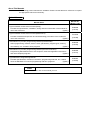
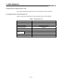
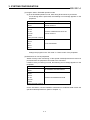
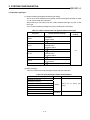
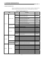
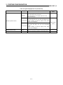
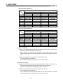
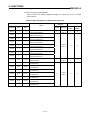
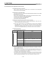
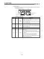
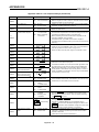
About This Manuals
The following product manuals are available. Please use this table as a reference to request
the appropriate manual as necessary.
Related Manuals
Manual Name
Manual No.
(Model Code)
Type A1FXCPU module user's manual (Setup)
Provides the specifications, installation, wiring and other information of the module for
use of the A1FXCPU.
(Option)
IB-66839
(13JL57)
Type A1FXCPU module user's manual (Maintenance)
Provides maintenance/inspection and troubleshooting procedures of the module for
use of the A1FXCPU.
(Option)
SH-4003
(13JL58)
ACPU/QCPU-A (A mode) Programming Manual (Fundamentals)
Offers programming methods, device names, parameters, program types, memory
area makeup, etc. needed to write programs.
(Option)
IB-66249
(13J740)
ACPU/QCPU-A (A mode) Programming Manual (Common Instruction)
Programming ManualGives how to use sequence, basic and application instructions
and microcomputer programs.
(Option)
IB-66250
(13J741)
Type MELSAP-II Programming Manual
Provides specifications, functions, instructions, programming methods, etc. needed
when the MELSAP-II is used for programming with SFC programs.
(Option)
IB-66361
(13JF40)
POINT
For the FX series, refer to the manual you use.
CONTENTS
About the Manuals
1. INTRODUCTION ·························································································································1-1 to 1-5
1.1 Features ······································································································································· 1-1
1.2 Functions Built in the A1FXCPU ··································································································· 1-2
1.3 Instructions for Use of the A1FXCPU ··························································································· 1-3
1.4 Packing List··································································································································· 1-5
2. PERFORMANCE·······················································································································2-1 to 2-29
2.1 Performance of the CPU Section·································································································· 2-1
2.1.1 CPU section performance list ······························································································· 2-1
2.1.2 Overview of operation processing ························································································ 2-3
2.1.3 Operation processing in RUN, STOP and PAUSE modes ··················································· 2-4
2.1.4 Operation processing at occurrence of an instantaneous power failure ······························ 2-5
2.1.5 Self-diagnosis ······················································································································· 2-6
2.1.6 Parameter setting range list·································································································· 2-9
2.1.7 Memory capacity (main program, file register, comment, etc.) setting······························· 2-10
2.2 Performance of the Power Supply Section ················································································· 2-12
2.2.1 Power supply section performance list ··············································································· 2-12
2.2.2 Number of extension points and 24VDC service power supply capacity ··························· 2-14
2.2.3 Number of special extension modules and blocks and 5VDC power supply capacity ······· 2-16
2.3 Performance of Simple Inter-PLC Link ······················································································· 2-18
2.3.1 Simple inter-PLC link performance list ··············································································· 2-18
2.3.2 Interface specifications ······································································································· 2-19
2.3.3 Specifications of the twisted pair cable··············································································· 2-20
2.4 Performance of Simple Positioning····························································································· 2-21
2.4.1 Simple positioning performance list···················································································· 2-21
2.4.2 Interface specifications ······································································································· 2-22
2.4.3 Output specifications ·········································································································· 2-23
2.5 Performance of the High-Speed Counter ··················································································· 2-24
2.5.1 High-speed counter performance list ················································································· 2-24
2.5.2 Interface specifications ······································································································· 2-25
2.6 Performance of the External Interrupt Function·········································································· 2-26
2.6.1 External interrupt function performance list········································································ 2-26
2.6.2 Interface specifications ······································································································· 2-27
2.7 Terminal Arrangement of the Built-in Function Connector ························································· 2-28
2.8 Performance Specifications of the Terminal Block ····································································· 2-29
3. SYSTEM CONFIGURATION ······································································································3-1 to 3-9
3.1 Overall Configuration ···················································································································· 3-1
3.2 System Configuration Instructions ································································································ 3-3
3.2.1 Hardware ······························································································································ 3-3
3.2.2 Software packages ··············································································································· 3-6
3.3 System Equipment List ················································································································· 3-7
4. NAMES OF PARTS AND THEIR SETTINGS ·············································································4-1 to 4-4
4.1 Names of Parts ····························································································································· 4-1
4.2 Settings ······································································································································· 4-3
2
4.2.1 RAM/E PROM operation setting ·························································································· 4-3
4.2.2 Write protect switch setting ·································································································· 4-3
4.3 Latch Clear Operation··················································································································· 4-4
5. FUNCTIONS······························································································································5-1 to 5-79
5.1 Function List·································································································································· 5-1
5.2 Simple Inter-PLC Link ··················································································································· 5-3
5.2.1 Instructions for simple inter-PLC link ···················································································· 5-4
5.2.2 Procedure for simple inter-PLC link······················································································ 5-5
5.2.3 Wiring for simple inter-PLC link ···························································································· 5-6
5.2.4 Data to be set for simple inter-PLC link ················································································ 5-7
5.2.5 Link parameter setting method··························································································· 5-10
5.2.6 Checking for errors in simple inter-PLC link ······································································· 5-13
5.2.7 Loopback self-check··········································································································· 5-18
5.3 Simple positioning control function ····························································································· 5-20
5.3.1 Instructions for the simple positioning control function······················································· 5-21
5.3.2 Procedure for simple positioning control ············································································ 5-22
5.3.3 Wiring for simple positioning control··················································································· 5-23
5.3.4 Setting for simple positioning control (setting of positioning data)······································ 5-28
5.3.5 Pulse output starting (positioning starting) and stopping signals········································ 5-33
5.3.6 Confirming the positioning statuses···················································································· 5-39
5.3.7 Checking for errors in simple positioning control································································ 5-41
5.3.8 Program examples ············································································································· 5-42
5.4 High-Speed Counter Function ···································································································· 5-51
5.4.1 Instructions for the high-speed counter function ································································ 5-52
5.4.2 Wiring for use of the high-speed counter function······························································ 5-53
5.4.3 Special relays/special registers for use of the high-speed counter function······················· 5-54
5.4.4 Preset function···················································································································· 5-61
5.4.5 Ring counter function·········································································································· 5-64
5.4.6 Count disable function ········································································································ 5-68
5.4.7 Latch counter function ········································································································ 5-69
5.4.8 Coincidence output function ······························································································· 5-70
5.5 External Interrupt Function·········································································································· 5-73
5.5.1 Instructions for the external interrupt function ···································································· 5-73
5.5.2 Wiring for use of the external interrupt function·································································· 5-74
5.5.3 Setting for executing the external interrupt function ··························································· 5-75
5.5.4 Interrupt processing timing ································································································· 5-77
6. I/O NUMBER ASSIGNMENT ······································································································6-1 to 6-3
6.1 What Are I/O Numbers? ··············································································································· 6-1
6.2 I/O Number Assignment ··············································································································· 6-2
7. COMMUNICATION WITH SPECIAL MODULE/SPECIAL BLOCK ···········································7-1 to 7-7
7.1 Reading 1- or 2-word data from the special module/special block
..... FROM, FROMP, DFRO, DFROP ························ 7-2
7.2 Writing 1- or 2-word data to the special module/special block ..... TO, TOP, DTO, DTOP ·········· 7-5
8. ERROR CODE LIST····················································································································8-1 to 8-4
APPENDICES··································································································· Appendix-1 to Appendix-26
Appendix 1 General Specifications ························································································ Appendix-1
Appendix 2 Outline Dimension Drawings··············································································· Appendix-3
Appendix 2.1 A1FXCPU module ······················································································ Appendix-3
Appendix 3 Available Instructions and Processing Time ······················································· Appendix-4
Appendix 3.1 Sequence instructions ················································································ Appendix-4
Appendix 3.2 Basic instructions························································································ Appendix-7
Appendix 3.3 Application instructions ············································································· Appendix-11
Appendix 4 List of Special Relays and Special Registers···················································· Appendix-15
Appendix 4.1 List of Special relays················································································· Appendix-15
Appendix 4.2 List of Special registers ············································································ Appendix-20
1. INTRODUCTION
MELSEC-A
1. INTRODUCTION
The A1FXCPU is a CPU module including a CPU, power supply and I/O (input: 14
points, output: 4 points) in one body and capable of control using A series instructions.
The A1FXCPU incorporates the simple inter-PLC link function, simple positioning
function, high-speed counter function and interrupt input function.
The FX series extension modules, extension blocks, special modules and special
blocks can be connected to the A1FXCPU to control them.
1.1 Features
The A1FXCPU module has the following features.
(1) CPU module having a power supply, CPU and I/O in one body
The A1FXCPU contains the power supply, CPU, I/O (input: 14 points, output: 4
2
points) and program memories (RAM, E PROM).
(2) Special functions incorporated in the CPU module
The CPU modules incorporates the simple inter-PLC link function, simple
positioning function, high-speed counter function and interrupt input function in
addition to the A2SHCPU functions.
(3) A series instructions available
The A series peripheral can be used to perform programming with the A series
instructions.
(4) FX series extension modules, extension blocks, special modules and special
blocks available
The FX2N and FX0N series extension modules, extension blocks and special
blocks can be used to configure up a compact system.
The FX1 and FX2 series extension modules and extension blocks can also be
connected to the A1FXCPU to make up a system.
(5) Data link with the FX2N and FX0N series
The simple inter-PLC link function allows bit data and word data to be
communicated with the FX2N and FX0N series.
(6) CE Mark compliant product
The A1FXCPU complies with the CE Mark.
For full information, refer to the A1FXCPU User's Manual (Setup).
1-1
1. INTRODUCTION
MELSEC-A
1.2 Functions Built in the A1FXCPU
The A1FXCPU has the following built-in functions.
(1) Simple inter-PLC link function
Up to eight A1FXCPU modules and FX2N and FX0N series main modules can be
connected by shielded, twisted pair cables to communicate bit and word data.
Master station
Local station
Local station
A1FXCPU
A1FXCPU
A1FXCPU
Shielded, twisted pair cable
(2) Simple positioning function
One servo amplifier and one stepping motor driver may be connected to the
A1FXCPU to do simple positioning with max. 60kpps pulses output.
A1FXCPU
Servo amplifier
Drive unit
Stepping motor
M
(3) High-speed counter function
Two encoders may be connected to the A1FXCPU to count max. 60kpps pulses
input. When the set value matches the count value, an interrupt program (I12,
I13) can be run.
A1FXCPU
Encoder
Encoder
(4) Interrupt input function
By switching on the interrupt terminals of the A1FXCPU external connector,
interrupt programs (I0 to I5) can be run by the A1FXCPU.
A1FXCPU
Switch, etc.
1-2
1. INTRODUCTION
MELSEC-A
1.3 Instructions for Use of the A1FXCPU
When using the A1FXCPU, follow these instructions.
2
(1) Switching between RAM and E PROM
2
The A1FXCPU incorporates RAM and E PROM and allows ROM operation
2
(E PROM) to be performed by setting the DIP switch to the corresponding
position. (The DIP switch is factory-set for RAM operation.)
For details, refer to Section 4.2.1.
(2) Assignment of I/O points
(a) The A1FXCPU controls the extension module/extension block inputs and
outputs in blocks of 16 points.
If the input extension module used is of 8 points, the number of I/O points is
calculated as 16 points.
Use the number of occupied points in Table 3.3 to calculate the number of I/O
points used with the A1FXCPU.
(b) One special module or special block occupies 8 I/O points.
Hence, the number of points used for special modules/special blocks is
decremented by 8 points per special module/special block.
However, the FX0N-16NT, FX-16NT and FX-16NP do not occupy 8 points.
(3) Assignment of I/O numbers
(a) The I/O numbers of the A1FXCPU are controlled in hexadecimal (X/Y 0 to
X/Y F).
The I/O numbers always begin with "X/Y 0".
(b) One special module or special block occupies the number of I/O points in
Table 3.3.
The I/O number assignment of a special module or special block having 8 I/O
points in Table 3.3 should be set in the same way as when there are no
special modules and special blocks.
Since the FX0N-16NT, FX-16NT and FX-16NP do not occupy 8 points, assign
their I/O numbers as in the I/O assignment of I/O blocks.
The FX0N-16NT-S3 and FX-16NT-S3 occupy 8 points and their I/O numbers
should be assigned as in the I/O number assignment of I/O blocks.
(c) For details of I/O number assignment, refer to Chapter 6.
(4) Communication with special module/special block
The FROM/TO instructions are used for communication with a special module/
special block. Note that the ways of specifying the FROM/TO instructions are
different.
For full information, refer to Chapter 7.
(5) Instructions for use of special modules/special blocks
The following special modules/special blocks continue operating normally when
the A1FXCPU is reset or an operation error occurs.
When it is necessary to stop their operations in user's system configuration,
make up an interlock circuit outside the PLC.
1-3
1. INTRODUCTION
MELSEC-A
(a) Special module/special block operations
• FX0N-3A : Analog outputs hold the RUN mode output states.
• FX-1GM : Continues positioning operation.
• FX-10GM : Continues positioning operation.
• FX-20GM : Continues positioning operation.
(b) Interlock circuit
Configure up a circuit to provide an interlock (stop external equipment
operation) when the output (Y) used as an interlock turns off.
(The output (Y) turns off when the A1FXCPU is reset or an operation error
occurs.)
Sequence program
M9036
Y20
A1FXCPU
24+
Keeps Y20 on
while A1FXCPU
is running.
Extension block
24+
MC
Y20
COM
Positioning module
FX-10GM
Stop switch
Stop
2
MC
COM
24+
POINT
The buffer memories of the above special modules and special block cannot be
initialized by the RESET switch of the A1FXCPU. Switch power off, then on
again or use a sequence program to initialize them.
(6) Type setting at startup of the peripheral
When using a peripheral for the A1FXCPU programming, start up the peripheral
with the PLC type "A1FX".
When using the SW3NX/IVD-GPPA or earlier, start up with "A2".
(7) FX series peripheral unavailable
For the A1FXCPU, the A series peripheral is used to perform programming with
the A series instructions.
The FX series peripheral cannot be used for programming.
1-4
1. INTRODUCTION
MELSEC-A
1.4 Packing List
After unpacking, confirm that there are the following products.
Product
Quantity
A1FXCPU module
1
32-pin connector
1
Battery (A6BAT)
1
Terminal resistor (110Ω, 1/2W)
1
I/O label
1
Link station number label
1
1-5
2. PERFORMANCE
MELSEC-A
2. PERFORMANCE
2.1 Performance of the CPU Section
This section provides the CPU section performance of the A1FXCPU.
2.1.1 CPU section performance list
Table 2.1 gives the CPU section performance list of the A1FXCPU.
Table 2.1 Performance List
Item
Performance
Control method
Repeated operation (using stored program)
I/O control method
Refresh system
Language dedicated to sequence control
Program language
Relay symbol words, logic symbolic words, MELSAP-II (SFC)
Sequence instruction : 26
Number of instructions (types)
Basic instruction
: 131
Application instruction : 93
Processing speed
0.25
(sequence instruction, μs/step)
Number of I/O points
Watchdog timer
(points) 224 (X/Y20 to 10FF)
(ms) 10 to 2000
Memory capacity
(k bytes)
Program capacity
(k steps)
Built-in RAM
: 64
2
2
Built-in E PROM : 32 (E PROM service life for writing: 100000 times)
Main sequence : Max. 14
Sub sequence : None
Internal relay (M)
(points) 1000 (M0 to 999)
A total of 2048 points of M
Latch relay (L)
(points) 1048 (L1000 to 2047)
and L are commonly used.
Step relay (S)
(points) 0
Must not be set.
Link relay (B)
(points) 1024 (B0 to 3FF)
Set in parameters
256
Timer (T)
(points)
100ms timer: Set time 0.1 to 3276.7s (T0 to 199)
10ms timer: Set time 0.01 to 327.67s (T200 to 255)
Set in parameters
100ms retentive timer: Set time 0.1 to 3276.7s
256
Counter (C)
(points)
Normal counter: Setting range 1 to 32767 (C0 to 255)
Interrupt program counter: Setting range 1 to 32767
(Counter used in interrupt program)
Data register (D)
(points) 1024 (D0 to 1023)
2-1
Set in parameters
2. PERFORMANCE
MELSEC-A
Table 2.1 Performance List (Continued)
Item
Performance
Link register (W)
(points) 1024 (W0 to 3FF)
Annunciator (F)
(points) 256 (F0 to 255)
File register (R)
(points) Max. 4096 (R0 to 4095)
Accumulator (A)
(points) 2 (A0, A1)
Index register (V, Z)
(points) 2 (V, Z)
Pointer (P)
(points) 256 (P0 to 255)
Interrupt pointer (I)
(points) 11 (10 to 15, 112, 113, 129 to 131)
Special relay (M)
(points) 256 (M9000 to 9255)
Special register (D)
(points) 256 (D9000 to 9255)
Number of comment points
(in increments of 64 points)
(points)
Max. 3648
Watchdog timer error, memory error, CPU error, I/O error, battery error
Self-diagnostic function
detection, etc.
Operation mode at error occurrence
Stop or continue selected
Output mode switching at the time of STOP Before-STOP operation status re-output or output after operation
to RUN
execution is selected.
Year, month, day, hour, minute, second, day of the week
(automatic judgment of leap year)
Clock function
Accuracy
-3.2 to + 3.5s (TYP. +2.1s) / d at 0 °C
-3.4 to + 5.3s (TYP. +2.1s) / d at 25 °C
-13.4 to + 3.6s (TYP. -3.2s) / d at 55 °C
Permissible instantaneous power failure
period
Outline dimensions
Weight
(ms)
10
(mm)(inch) 130(5.12)(W) × 90(3.55)(H) × 87(3.43)(D)
(kg)(lb) 0.56(1.24)
2-2
2. PERFORMANCE
MELSEC-A
2.1.2 Overview of operation processing
This section provides the overview of processing from power-on of the A1FXCPU to
run of the sequence program.
A1FXCPU processing is roughly divided into the following.
(1) Initial processing
Pre-processing for execution of sequence operation. Performed only once when
power is switched on or the CPU is reset by the RESET switch.
(a) When there is a link setting program, the link parameters for simple inter-PLC
link are registered. (Refer to Section 5.2.)
(b) The extension module/extension block outputs are reset and initialized.
(c) The unlatched areas of data memory are initialized (bit devices are turned off
and word devices set to 0).
Note that file registers are not initialized.
(d) The I/O addresses of the extension modules/extension blocks connected to
the A1FXCPU are allocated automatically.
(e) Self-diagnostic check is performed on parameter setting, operation circuit, etc.
(Refer to Section 2.1.4.)
(2) Sequence program operation processing
The sequence program written to the A1FXCPU is run from step 0 to the END
(FEND) instruction.
(3) END processing
Post-processing performed to terminate single sequence program operation
processing and return sequence program run to step 0.
(a) Self-diagnostic check is made for power-off, I/O module verify error, battery
low, etc. of the extension modules/extension blocks. (Refer to Section 2.1.4.)
(b) The present values of timers and counters are updated and their contacts
switched on/off.
(For more information on the timers and counters, refer to the ACPU
Programming Manual (Basics).)
(c) When the sampling trace point is per scan (after execution of the END
instruction), the statuses of preset devices are stored into the sampling trace
area.
(d) When a refresh request is given during use of simple inter-PLC link, link
refresh processing is carried out.
(e) When the simple positioning function is used, pulse output start/stop processing
is performed.
(f) The extension modules/extension blocks are I/O refreshed (ON/OFF data
updated). (For details of refresh processing, refer to the ACPU Programming
Manual (Basics).)
2-3
2. PERFORMANCE
MELSEC-A
2.1.3 Operation processing in RUN, STOP and PAUSE modes
The A1FXCPU has three different operation modes: "RUN mode", "STOP mode"
and "PAUSE mode".
This section describes the operation processing of the PLC CPU performed in each
mode.
(1) Operation processing in RUN mode
In the RUN mode, sequence program operation is repeated in sequence of step
0 to END (FEND) instruction to step 0.
When entering the RUN mode, the CPU outputs the output status saved in the
STOP mode according to the STOP→RUN output mode setting in the parameter.
Processing time up to the start of sequence program operation, which depends
on the system configuration, is as follows:
• When power is switched on or the CPU is reset by RESET switch : 2 to 3s
• When the CPU is switched from STOP to RUN
: 1 to 3s
(2) Operation processing in STOP mode
In the STOP mode, sequence program operation is stopped by:
• Moving the RUN/STOP switch to the STOP position.
• Executing the STOP instruction in the sequence program.
• Performing remote STOP from the peripheral.
• Turning on the remote STOP contact. *1
When entering the STOP mode, the A1FXCPU saves the output status internally
and turns off all extension module/extension block outputs (Y). *2
Data memories other than the outputs (Y) are latched.
(3) Operation processing in PAUSE mode
In the PAUSE mode, the outputs (Y) and data memories are latched and sequence
program operation is stopped by:
• Performing remote PAUSE from the peripheral.
• Turning on the remote PAUSE contact and PAUSE enable contact (M9040). *1
POINT
In any of the RUN, STOP and PAUSE modes, the A1FXCPU is making:
• Communication with the peripheral
• Refresh processing of extension modules/extension blocks
• Link refresh of simple inter-PLC link
Therefore, I/O monitoring and test operation can be performed from the
peripheral equipment in the STOP and PAUSE modes.
REMARKS
*1: Set the remote STOP and remote PAUSE contacts in parameters from the
peripheral.
*2: When the peripheral is used to monitor the outputs (Y), they all turn off.
2-4
2. PERFORMANCE
MELSEC-A
2.1.4 Operation processing at occurrence of an instantaneous power failure
The A1FXCPU detects an instantaneous power failure when the input source voltage
supplied to the power supply section of the A1FXCPU drops below the specified
value.
On detection of an instantaneous power failure, the A1FXCPU performs the following
operation processing.
(1) Instantaneous power failure shorter than permissible instantaneous power failure
time
(a) When an instantaneous power failure has occurred, the A1FXCPU holds the
output status and suspends operation processing.
(b) When an instantaneous power failure is cleared, the A1FXCPU resumes
operation processing.
At this time, it adds 1 to the AC down detection storing special register (D9005).
(c) If operation is being suspended due to the occurrence of an instantaneous
power failure, the A1FXCPU continues the timing of the watchdog timer (WDT).
For example, when the watchdog timer setting is 200ms, a watchdog timer error
occurs if an instantaneous power failure of 10ms occurs at the scan time of
195ms.
Occurrence of
instantaneous
power failure
A1FXCPU
operation
END
Step 0
Restoration of
power supply
END Step 0
A1FXCPU suspends operation.
Fig. 2.1 Operation Processing at Occurrence of Instantaneous Power Failure
(2) Instantaneous power failure longer than permissible instantaneous power failure
time
The A1FXCPU makes an initial start.
When making an initial start, the A1FXCPU performs the same operation
processing as when power is switched on or the CPU is reset by the RESET switch.
POINT
When the AC down detection storing special register (D9005) is incremented,
check the power supplied to the A1FXCPU.
2-5
2. PERFORMANCE
MELSEC-A
2.1.5 Self-diagnosis
Self-diagnosis is a function that the A1FXCPU self-checks for a error.
The self-diagnostic function of the A1FXCPU detects an error which occurs at
power-on or during run and displays the corresponding error message and stops
operation to prevent a PLC malfunction and perform preventive maintenance.
The A1FXCPU has two different operation modes for self-diagnosed errors:
operation stop mode and operation continuation mode.
For some errors, the continuation mode may be changed into the stop mode. (Refer
to Table 2.2.)
The occurrence and definition of the error detected are stored into the corresponding
special relay (M) and special register (D). (Refer to Appendix 4.)
Especially in the continuation mode, use the special relays and special registers in
the program to prevent PLC or mechanical system malfunctions.
In the operation stop mode, the A1FXCPU stops operation and switches off all
outputs (Y) on detection of an error.
In the operation continuation mode, the A1FXCPU runs the program with the
exception of a faulty part.
When an I/O module verify error has occurred, the A1FXCPU continues operation at
the I/O addresses prior to the occurrence of the error.
Table 2.2 on the next page indicates self-diagnosed errors.
2-6
2. PERFORMANCE
MELSEC-A
Tale 2.2 Self-Diagnosis List
Diagnosis
Instruction code check
Parameter setting check
No END instruction
Memory error
Instruction execution
disable
Format (CHK) check
Instruction execution
disable
RAM check
CPU error
I/O error
Special
function
module error
Operation circuit check
CPU
Status
RUN LED
Status
• When that instruction is executed
• When power is switched on or
CPU is reset
• When (STOP/PAUSE) is switched
to (RUN)
• When (STOP/PAUSE) is switched
to (RUN)
• When CJ, SCJ, JMP, CALL(P) or
FOR-NEXT instruction is executed
• When (STOP/PAUSE) is switched
to (RUN)
• When (STOP/PAUSE) is switched
to (RUN)
• When interrupt occurs
• When (STOP/PAUSE) is switched
to (RUN)
• When power is switched on or
CPU is reset
• When M9084 is switched on in
STOP mode
• When power is switched on or
CPU is reset
Watchdog error monitor
• When END instruction is executed
END instruction not
executed
• When END instruction is executed
Stop
Stop
Error Display of
Peripheral
Error
Code
INSTRCT CODE ERR.
10
PARAMETER ERROR
11
MISSING END INS.
12
CAN'T EXECUTE (P)
13
CHK FORMAT ERR.
14
CAN'T EXECUTE (I)
15
RAM ERROR
20
OPE CIRCUIT ERR.
21
WDT ERROR
22
END NOT EXECUTE
24
Flicker
Flicker
Endless loop execution
• Always
WDT ERROR
25
Main CPU check
• Always
MAIN CPU DOWN
26
I/O module verify
(Default: Stop)
• When END processing is executed Stop
(Not checked when M9084 is on)
UNIT VERIFY ERR.
31
Power off
(Default: Continuation)
• When END processing is executed
(Not checked when M9084 is on)
FUSE BREAK OFF
32
Control bus check
• When FROM/TO instruction is
executed
CONTROL BUS ERR.
40
Special function module
error
• When FROM/TO instruction is
executed
SP. UNIT DOWN
41
I/O interrupt error
• When interrupt occurs
I/O INT. ERROR
43
Special function module
assignment error
• When power is switched on or
CPU is reset
• When (STOP/PAUSE) is switched
to (RUN)
SP. UNIT LAY ERR.
44
Special function module
access error
(Default: Stop)
• When FROM/TO instruction is
executed
SP. UNIT ERR.
46
Link parameter error
Battery
Diagnosis Timing
Battery error
Operation error
(Default : Continuation)
• When power is switched on or
CPU is reset
• When (STOP/PAUSE) is switched
to (RUN)
• Always
(Not checked when M9084 is on)
• When corresponding instruction is
executed
2-7
Flicker
Run
Stop
On
Flicker
Flicker
Stop
On
Run
Run
On
LINK PARA ERROR
47
Run
On
BATTERY ERROR
70
OPERATION ERROR
50
Flicker
Stop
Run
On
2. PERFORMANCE
MELSEC-A
REMARKS
1) Two modes described in the "CPU Status" and "RUN LED Status" columns in
Table 2.2 indicate that they can be changed by parameter setting from the
peripheral.
2) The messages given in "Error Message of Peripheral" of Table 2.2 are
displayed when the peripheral is used to make PLC diagnosis.
3) *: FUSE BREAK OFF is displayed in the peripheral device.
2-8
2. PERFORMANCE
MELSEC-A
2.1.6 Parameter setting range list
Parameters are used to assign the A1FXCPU's user memory, set various functions,
and specify device ranges.
The set data is stored in the first 3k bytes of the user memory area.
Default (initial) parameter values as indicated in Table 2.3 may be selected or the
user may change the setting ranges according to the purposes of use from the
peripheral device.
Table 2.3 Parameter Setting Range List
Default Value
Setting Range
Main sequence program
Item
(k steps)
6
1 to 14
File register
(k bytes)
None
0 to 4
Comment capacity
(points)
None
0 to 3648
Status latch
(k bytes)
None
0/8 to 16
Sampling trace
(k bytes)
None
Latch range setting
0/8
Link relay (B)
B0 to B3FF
(in units of 1 point)
Timer (T)
T0 to T255
(in units of 1 point)
Counter (C)
• Only L1000 to L2047 are
latched.
• None for other devices.
C0 to C255
(in units of 1 point)
Data register (D)
D0 to D1023
(in units of 1 point)
Link register (W)
W0 to W3FF
(in units of 1 point)
M0 to M999
Internal relay (M), latch relay (L), step relay
L1000 to L2047
(S) setting
None for S
M/L0 to M/L2047
T0 to T199 (100ms)
T200 to T255 (10ms)
Timer setting
Interrupt counter setting
None
I/O number assignment
None
Remote RUN/STOP, PAUSE contact
setting
Remarks
Step relay (S) must not
be set. (If set, parameter
error occurs.)
Total 256 points of 100ms, 10ms
and retentive timers
Total 256 points of counters and
interrupt counters (in units of 8
points)
These counters are processed in
numerical order.
None
Setting is invalid.
X0 to XFF
1 point each for RUN and STOP
X100 to X1FF must not
contacts.
be set.
(Setting of PAUSE contact alone
is not allowed)
⎯⎯
Fuse
Operation mode at
time of error
I/O module verify error
Operation error
Stop
Stop/continuation
Special function
module check error
Operation status prior to Output prior to stop or after
stop is re-output.
operation execution.
STOP→RUN output mode
Print title registration
None
Up to 128 characters
Keyword registration
None
Hexadecimal (0 to 9, A to F)
Max. 6 digits
Link range setting
None
None
Setting is invalid.
*:Operation mode setting at error occurrence in the peripheral device parameters is done with FUSE
BREAK OFF.
2-9
2. PERFORMANCE
MELSEC-A
2.1.7 Memory capacity (main program, file register, comment, etc.) setting
2
The A1FXCPU is standard-equipped with 64k byte RAM and 32k byte E PROM.
2
The DIP switch of the A1FXCPU is used to switch between RAM and E PROM.
(For the DIP switch setting, refer to Section 4.2.1.)
The following data are stored in 64k byte RAM.
• Parameters
• T/C set values
• Main program
• Sampling trace data
• Status latch data
• File registers
• Comments
2
32k byte E PROM is used for ROM operation of the A1FXCPU and can store the
following data.
• Parameters
• T/C set values
• Main program
(1) Memory capacity calculation
2
Use RAM/E PROM after determining stored data types and memory capacities
by parameter setting.
Use Table 2.4 to calculate memory capacities.
Table 2.4 Parameter Setting and Memory Capacity List
Item
Setting
Increments
Parameters, T/C set values
Sequence
program
Main program
Microcomputer
program
Sampling trace
Data memory
Storage into
2
E PROM
Remarks
4k bytes (fixed)
1k step
Main sequence
program capacity
2k bytes
2k bytes
Main
microcomputer
program capacity
2k bytes
Allowed
No/yes
0/8k bytes
No/yes
0/8k bytes
Status latch
File registers
Memory Capacity
No/yes
File registers
1k points
Comments
64 points
File register
k bytes
memory capacity
File register
points
2k bytes
(Comment points)
64
2 - 10
+ 1k byte
Disallowed
Memory capacity for file
Disallowed
register status latch is the
file register capacity set in
parameter.
Disallowed
Disallowed
Comment capacity setting
occupies 1k byte in system.
2. PERFORMANCE
MELSEC-A
(2) Sequence of data storage into user memory
(a) Various data set in parameters are stored in the sequence shown in Fig. 2.2.
(b) Before performing write protect, make sure that the sampling trace, file
register and other areas where data is written during sequence program
execution are not in the write protect range.
2
(c) If the main program is stored in E PROM, the system uses the area where the
main program was stored in the RAM operation mode.
2
Hence, if E PROM operation is performed, the sampling trace, status latch,
file register and comment capacities cannot be increased.
(a) RAM operation
(b) E2PROM operation
Parameters
T/C set values
E2PROM capacity
(32k bytes)
Sequence program
(At least 1k step required)
Microcomputer program
Not used
Must not be used.
Parameters
T/C set values
Sequence program
Write protect range
(At least 1k step required)
(32k bytes)
Microcomputer program
Not used
RAM capacity
(64k bytes)
Extension file registers
Not write protected
Write
Write protect
Peripheral range
Read
Must not be used.
(Used by system)
Not write
protected
Not used
Extension file registers
Sampling trace area
Sampling trace area
Status latch area
Status latch area
File register area
File register area
Comment area
Comment area
Made usable by
SW0GHP-UTLP-FN1
Fig. 2.2 Sequence of Data Storage into User Memory
(3) Procedure for writing parameters, T/C set values and sequence program to
2
E PROM
2
Write parameters, T/C set values and sequence program to E PROM in the
following procedure.
• On the peripheral, read the parameters, T/C set values and sequence program
from RAM.
(Read from RAM is not required when above data were stored on the
programming peripheral in the RAM operation mode.)
• Move the DIP switch to the "ROM" position.
• Switch power on again.
• Write the parameters, T/C set values and sequence program from the
2
peripheral to E PROM.
REMARKS
1) In Fig. 2.2, parameters occupy 3k bytes and T/C set values 1k byte.
1 to 14k steps (2 to 28k bytes) can be set to the sequence program.
2 - 11
2. PERFORMANCE
MELSEC-A
2.2 Performance of the Power Supply Section
This section provides the power supply section performance of the A1FXCPU.
2.2.1 Power supply section performance list
Table 2.5 gives the power supply section performance list of the A1FXCPU.
Table 2.5 Performance List
Item
Performance
100-240VAC +10% -15%
Input voltage
(85-264VAC)
50/60Hz ±3Hz
Input frequency
Input apparent power
100VA
Inrush current
50A 5ms at input of 240VAC *4
5VDC 1.2A/24VDC 0.41A [MAX] (for CPU, I/O)
Rated output *1
24VDC 0.43A (for external service power supply) *2, *3
5VDC 1.5A or more/24VDC 0.65A or more
Overcurrent protection
(total for insulation and non-insulation) *5
Overvoltage protection
5.5 to 6.5vDC *6
Efficiency
65% or more
Power indication
POWER LED indication
Terminal screw size
M3×8
Applicable wire size
0.3 to 2mm
2
• RAV1.25-3 R1.25-3 (in conformance with JIS C 2805)
2
[Applicable wire size: 0.3 to 1.25mm ]
Applicable solderless terminal
• V2-MS3 (Japan Solderless Terminal Mfg. Co., Ltd.),
RAP2-3SL RAP2-3.5SL (Japan Terminal Co., Ltd.)
2
[Applicable wire size: 1.25 to 2mm ]
Permissible instantaneous power
failure period
Within 10ms *7
*1: For details, refer to Sections 2.2.2 and 2.2.3.
*2: For external service power supply : 0.3A
Total 0.43A
For built-in functions
: 0.13A
*3: 24VDC can be used up to a total of 0.6A for the CPU, I/O and external service
power supply.
*4: Inrush current
If the power supply module is re-powered ON right after powered OFF (within
5seconds), the inrush current exceeding the specified value (2ms or less) may be
generated. Therefore, make sure to re-power ON the module 5seconds after
power off.
When selecting a fuse or breaker for external circuit, consider the above point as
well as meltdown and detection characteristics.
2 - 12
2. PERFORMANCE
MELSEC-A
*5: Overcurrent protection
The overcurrent proctection device shuts off the 5VDC and/or 24VDC circuit(s)
and stops the system if the current exceeding the specified value flows in the
circuit(s).
As this results in voltage drop, the power supply module LED turns OFF or is
dimly lit.
After that, eliminate the causes of overcurrent, e.g., insufficient current capacity
and short circuit, and then start the system.
When the current has reached the normal value, the initial start up of the system
will be performed.
*6: Overvoltage protection
The overvoltage protection shuts off the 5VDC circuit and stops the system if the
overvoltage of 5.5 to 6.5V is applied to the circuit.
This results in the power supply module LED turning OFF.
When restarting the system, power OFF and ON the input power supply, and the
initial start up of the system will be performed.
If the system is not booted and the LED remains off, this means that the power
supply module has to be replaced.
*7: Allowable momentary power failure period
The PLC CPU allowable momentary power failure period varies with the power
supply module used.
In case of the A1S63P power supply module, the allowable momentary power
failure period is defined as the time from when the primary side of the stabilized
power supply for supplying 24VDC to the A1S63P is turned OFF until when the
voltage (secondary side) has dropped from 24VDC to the specified value
(15.6VDC) or less.
REMARKS
For the power supply specifications of the extension module, refer to the
A1FXCPU User's Manual (Setup).
2 - 13
2. PERFORMANCE
MELSEC-A
2.2.2 Number of extension points and 24VDC service power supply capacity
The A1FXCPU and extension module supply 24VDC power to extension blocks.
Therefore, the number of extension block points connected must be within the range
in which the A1FXCPU and extension module can supply power.
Since 0.13A out of servicing power supply 24VDC is used for the built-in functions,
the 24VDC external service power supply capacity is max.
0.3A (0.43A-0.13A=0.3A)
(1) Power supplying range
The A1FXCPU or extension module can supply 24VDC service power in the
following range.
B
B: Extension block
FX2N
extension
module
B
B
Special
B
B
A1FXCPU
24VDC supplied
Special
B
24VDC supplied
Special B: Special block
The A1FXCPU or extension module supplies 24VDC current to extension locks in
the extension module connected next.
When the extension block is designed for input, the power supply for input
equipment drive requires external wiring. Special blocks are supplied with 5VDC
power.
(2) 24VDC capacity calculation
The capacity of the 24VDC service power supply depends on the model.
<24VDC service power supply capacity>
Model
Power Supply Capacity
A1FXCPU
300mA
FX2N-32E
250mA
FX2N-48E
460mA
Remarks
Power supplied to extension blocks
Extension blocks designed for input and output differ in current consumption.
Current consumption less than the total capacity indicates that extension blocks
can be connected.
Remaining power may be used for sensors, output loads, etc.
Total service power
supply capacity
300mA,
250mA or 460mA
Extension block
for FX2N/FX0N
input
8 points,50mA
Number of
blocks
connected
-
Extension block
for FX2N/FX0N
output
8 points, 75mA for
24 or more points
Number of
blocks
connected
0 (remaining power for sensors and loads)
If the result is less than 0, the capacity is short.
Use an extension module midway.
Connection example: A1FXCPU, FX0N-8EX, FX2N-16EX, FX0N-8EYR
300mA - 50mA 1 - 50mA 2 - 0mA 1 = 150mA
0 (may be connected)
Remaining 24VDC
service power
Because of less than 24
output points
2 - 14
2. PERFORMANCE
MELSEC-A
(3) Quick calculation table
The following tables represent capacity formulas with specific values.
They can be used to determine whether extension blocks may be connected or
not and to find the remaining 24VDC service power.
A1FXCPU
When the FX0N-3A is not used
(mA)
Number of output
extension points
Example: When 16 input points and 24
output points are added, 24VDC
service current is 125mA or less.
40
75
25
32
150
100
50
24
225
175
125
75
25
16
300
250
200
150
100
50
8
300
250
200
150
100
50
0
300
250
200
150
100
50
0
8
16
24
32
Number of input
extension points
40
0
When the FX0N-3A is used (up to 2 FX0N-3A's may be connected)
24
50
16
125
75
Example: When 16 input points and 8
output points are added, 24VDC
service current is 100mA or less.
25
8
200
150
100
50
0
275
225
175
125
75
25
0
8
16
24
32
40
(mA)
Number of output
extension points
0
0
Number of input
extension points
When FX2N-32E is used
(mA)
Number of output
extension points
Example: When 8 input points and 8
output points are added, 24VDC
service current is 125mA or less.
24
25
16
100
50
0
8
175
125
75
25
0
250
200
150
100
50
8
16
24
Number of input
extension points
32
0
When FX2N-48E is used
(mA)
48
Number of output
extension points
10
Example: When 16 input points and 16
output points are added, 24VDC
service current is 210mA or less.
40
85
35
32
160
110
60
24
235
185
135
85
35
16
310
260
210
160
110
60
8
385
335
285
235
185
135
85
35
0
460
410
360
310
260
210
160
110
60
0
8
16
40
48
56
64
2 - 15
10
24
32
Number of input
extension points
10
2. PERFORMANCE
MELSEC-A
2.2.3 Number of special extension modules and blocks and 5VDC power supply capacity
When special modules and special blocks are used, the number of modules and
blocks connected and 5VDC current consumption must be taken into consideration.
(1) Number of modules and blocks connected
Up to eight special modules/special blocks may be connected to the A1FXCPU.
(2) Power supply range
Special blocks are supplied with 5VDC in the following range.
B
Special U
FX2N
extension
module
Special B
B
Special
B
A1FXCPU
Special B
5VDC supplied
5VDC supplied
FX2N-CNV-IF
B: Extension block Special B: Special block Special U: Special module
The A1FXCPU or extension module supplies 5VDC power to the special blocks
in the extension module connected next. (The special module does not include a
power supply.)
As 5VDC power is supplied through the extension cable, external wiring is not
necessary.
(3) 5VDC capacity calculation
The 5VDC power supply of each module is as follows. Refer to the following table
for the current consumption of each special block.
<5VDC power supply capacity>
Model
Power Supply Capacity
Remarks
A1FXCPU
300mA
The 5VDC current to the CPU and
FX2N extension module
690mA
the equipment connected to the
programming connector has already
been subtracted.
5VDC
Total capacity
300mA or 690mA
-
Special block
5VDC
Current consumption
Refer to Table 2.6.
0
If the result is less than 0, the capacity is short.
Use an extension module midway.
Up to two FX0N-3A's may be connected to the A1FXCPU or FX2N-32E, or up to three FX0N-3A's to the
FX2N-48E. If more blocks are connected, use the extension module (FX2N-32E, FX2N-48E) midway.
Connection example: A1FXCPU, FX0N-3A 2, FX-IHC 1 , FX-10GM 1
300mA - (30 ´ 2)mA - 70mA - 0mA (power supply built-in: unnecessary)=170mA 0 (connectable)
2 - 16
2. PERFORMANCE
MELSEC-A
Table 2.6 Special Block and Special Module Current Consumption List
Current
Model
Type
Name
Consumption
(5VDC)
FX0N-3A
2-channel analog input, 1-channel analog output
30mA
FX0N-16NT
For M-NET/MINI (twisted wire)
20mA
FX2N-4AD
4-channel analog input
30mA
FX2N-4DA
4-channel analog output
30mA
FX2N-4AD-PT
4-channel temperature sensor input (PT-100)
30mA
FX2N-4AD-TC
Special
block
30mA
50kHz 2-phase high-speed counter
90mA
FX2N-1PG
100kpps pulse output block
55mA
FX2N-232IF
RS-232C communication interface
40mA
FX-16NP *
For M-NET/MINI (optical fiber)
80mA
FX-16NT *
For M-NET/MINI (twisted wire)
80mA
FX-16NP-S3 *
For M-NET/MINI-S3 (optical fiber)
80mA
FX-16NT-S3 *
For M-NET/MINI-S3 (twisted wire)
80mA
FX-2DA *
2-channel analog output
30mA
FX-4DA *
4-channel analog output
30mA
FX-4AD *
4-channel analog input
30mA
2-channel temperature sensor input (PT-100)
30mA
FX-4AD-TC *
module
(thermocouple)
FX2N-1HC
FX-2AD-PT *
Special
4-channel temperature sensor input
(thermocouple)
40mA
FX-1HC *
50kHz 2-phase high-speed counter
70mA
FX-1PG *
100kpps pulse output block
55mA
FX-1DIF *
ID interface
130mA
FX-1GM *
Positioning pulse output module (1 axis)
Self-supply
FX-10GM *
Positioning pulse output module (1 axis)
Self-supply
FX-20GM *
Positioning pulse output module (2 axes)
Self-supply
* The FX2N-CNV-IF conversion adaptor is required for use of special modules and
special blocks.
2 - 17
2. PERFORMANCE
MELSEC-A
2.3 Performance of Simple Inter-PLC Link
This section provides the simple inter-PLC link performance of the A1FXCPU.
2.3.1 Simple inter-PLC link performance list
Table 2.7 gives the simple inter-PLC link performance list of the A1FXCPU.
Table 2.7 Performance List
Item
Performance
Interface
Conformance with RS-485
Communication method
Half duplex communication system
Synchronous method
Asynchronous system
Transmission speed
38400bps
Total transmission distance
Max. 500m
Number of stations
Data
8 stations
Bit data
0, 32 or 64 bits/station
Word data
4 or 8 words/station
Data communication method
N:N
Link scan time
Max. 200ms
2 - 18
2. PERFORMANCE
MELSEC-A
2.3.2 Interface specifications
Table 2.8 gives the RS-485 interface specification list of the A1FXCPU.
Table 2.8 Specification List
Signal Abbreviation
Signal Direction
Module↔Module
Description
SDA/RDA
↔
Send/receive data
SDB/RDB
↔
Send/receive data
SG
↔
Signal ground
Wiring method
Master station
Local station
Local station
SDA/RDA
SDA/RDA
SDA/RDA
SDB/RDB
SDB/RDB
SDB/RDB
SG
SG
SG
SLD
SLD
SLD
FG
FG
FG
R
R
Terminal
resistor
Terminal
resistor
Shielded, twisted pair cables
POINT
Connect both ends of the shield wire of the twisted pair cable to the ground
(ground conductor with class D (class-3)) via "SLD" and "FG" of each module.
SLD and FG are connected inside the module.
2 - 19
2. PERFORMANCE
MELSEC-A
2.3.3 Specifications of the twisted pair cable
Table 2.9 indicates the specifications of the cable that may be used in simple
inter-PLC link of the A1FXCPU.
Table 2.9 Twisted Pair Cable Specifications
Item
Specifications
Cable type
Shielded twisted pair cable
Number of pairs
2 pairs or more
Conductor resistance (20°C)
88.0Ω/km or less
Capacitance (1kHz)
Average 60nF/km or less
Characteristic impedance
110±10Ω
(100kHz)
REMARKS
The manufacturers and types of the recommended shielded twisted pair cables
are as follows.
Manufacturer
Mitsubishi Cable Industries
Showa Electric Wire & Cable
Sumitomo Electric Industries
Furukawa Electric
Fujikura
Type
Remarks
2
SPEV (SB) - 0.2 - 2P
0.2mm 2-pair cable
SPEV (SB) - 0.5 - 2P
0.5mm 2-pair cable
KMPEV-SB CWS-178 0.2SQ×2P
0.2mm 2-pair cable
KMPEV-SB CWS-178 0.5SQ×2P
0.5mm 2-pair cable
DPEV SB 0.3×3P
0.3mm 2-pair cable
DPEV SB 0.5×3P
0.5mm 2-pair cable
D-KPEV-SB 0.2×3P
0.2mm 2-pair cable
D-KPEV-SB 0.5×3P
0.5mm 2-pair cable
2
2
2
2
2
2
2
0.3mm 2-pair cable
2
0.5mm 2-pair cable
IPEV-SB 0.3mm ×2P
IPEV-SB 0.5mm ×2P
2 - 20
2
2
2
2. PERFORMANCE
MELSEC-A
2.4 Performance of Simple Positioning
This section provides the simple positioning performance of the A1FXCPU.
2.4.1 Simple positioning performance list
Table 2.10 gives the simple positioning performance list of the A1FXCPU.
Table 2.10 Performance List
Item
Performance
Number of axes controlled
Number of
2 axes
Capacity
1
positioning data Setting method
Control unit
By sequence program
pulse
Positioning system
Position control
Acceleration/deceleration
Automatic trapezoidal acceleration/deceleration
processing
Acceleration/deceleration time
1 to 32767 (ms)
Output pulse range
0 to 16777215 (pulse)
Output pulse speed
1 to 60000 pps
Starting bias speed
1 to 60000 pps
Error indication*1
Special relay
Positioning data storage destination
*1: For details, refer to Section 5.3.4.
2 - 21
Special register
2. PERFORMANCE
MELSEC-A
2.4.2 Interface specifications
Table 2.11 gives the simple positioning interface specification list of the A1FXCPU.
Table 2.11 Specification List
Item
Specifications
Number of output points
4 points (positioning pulse output 2 axes×2 points, Y10 to 13)
Output form
Transistor (open collector) output
Rated load voltage
5-15/24VDC
Operating load voltage range
4.75 to 16.5VDC (at 5-15VDC)/21.6 to 26.4VDC (at 24VDC)
Max. load current/inrush current
50mA/point, 200mA 10ms or less (at 25°C)
Min. load current
2mA (when it is less than 2mA, a dummy resistor should be added.)
Max. voltage drop at ON
0.5VDC or less
Leakage current at OFF
0.1mA or less
Common method
2 points-1 common
(Y10 COM and Y12 COM, and Y11 COM and Y13 COM are connected internally)
External wiring
Photocoupler
Photocoupler
A1FXCPU
X/YDC5
X axis
MR-J
A12/B12
PP
A11/B11
X/YDC5
SG
NP
A14/B14
SD
A13/B13
A15/B15
X/YDC5
A16/B16
VDD
B16
B15
B14
B13
B12
B11
B10
B9
B8
B7
B6
B5
B4
B3
B2
B1
A16
A15
A14
A13
A12
A11
A10
A9
A8
A7
A6
A5
A4
A3
A2
A1
Y axis
Terminal
Signal
Terminal
Signal
Number
Name
Number
Name
B16
YDC5
A16
XDC5
B15
TDC24
A15
XDC24
B14
Y13
A14
Y12
B13
Y13 COM
A13
Y12 COM
B12
Y11
A12
Y10
B11
Y11 COM
A11
Y10 COM
B10
⎯
A10
⎯
B9
⎯
A9
⎯
B8
⎯
A8
⎯
B7
⎯
A7
⎯
B6
⎯
A6
⎯
B5
⎯
A5
⎯
B4
⎯
A4
⎯
B3
⎯
A3
⎯
B2
⎯
A2
⎯
B1
⎯
A1
⎯
⎯ : Indicates the terminal which is not used with this function.
POINT
For use of the X axis·········Connect the power supply to XDC5 at 5-15VDC or to
XDC24 at 24VDC.
For use of the Y axis·········Connect the power supply to YDC5 at 5-15VDC or to
YDC24 at 24VDC.
2 - 22
2. PERFORMANCE
MELSEC-A
2.4.3 Output specifications
(1) Pulse output
The following table lists the relationships between pulse output switching and
pulse outputs by pulse output logic switching setting. (Refer to Section 5.3.4):
Output
Terminals
Positive Logic
Pulse Output
Method
Forward
rotation
Negative Logic
Reverse
rotation
Forward
rotation
X axis
Y axis
Y10
Y11
CW
High
Low
High
Low
Y12
Y13
CCW
High
Low
High
Low
Y10
Y11
PULSE
High
Low
High
Low
Y12
Y13
SIGN
High
Low
High
Low
Reverse
rotation
(2) Pulse rise/fall time
The following table lists the pulse rise and fall times at the ordinary ambient
temperature.
Table 2.12 Pulse Rise/Fall Time at Normal Temperatures
Load voltage (V)
26.4
Cable length (m)
1
Load current
Pulse speed
(mA)
(kpps)
2
10
50
60
4.75
2
1
2
tf
tr
Duty
tf
tr
Duty
tf
tr
Duty
tf
tr
Duty
0.1
3.4
41
0.1
5.0
39
0.1
0.8
48
0.1
1.1
49
10
0.1
4.0
48
0.1
5.7
48
0.1
0.9
50
0.1
1.2
50
60
0.1
0.7
48
0.1
1.1
46
0.1
0.3
50
0.1
0.4
50
10
0.1
0.9
50
0.1
1.3
50
0.1
0.3
50
0.1
0.4
50
60
0.1
0.3
48
0.1
0.4
49
0.2
0.3
50
0.2
0.3
50
10
0.1
0.4
50
0.1
0.4
50
0.2
0.3
50
0.2
0.3
50
(Units = tf, tr : μs, Duty : %)
REMARKS
1) In Table 2.12, tr indicates a pulse rise time and tf its fall time.
ON
OFF
tr
tf
2 - 23
2. PERFORMANCE
MELSEC-A
2.5 Performance of the High-Speed Counter
This section provides the high-speed counter performance of the A1FXCPU.
2.5.1 High-speed counter performance list
Table 2.13 gives the high-speed counter performance list of the A1FXCPU.
Table 2.13 Performance List
Item
Specifications
Counting speed selection setting
1 phase/2 phase: 60kpps/1 phase: 10kpps, 2 phase: 7kpps
Number of channels
2 channels
Phase
Count input
1-phase input, 2-phase input
CH.1 φA: XA, φB: XC
Count input signal
CH.2 φA: XB, φB: XD
1-phase input multiplied by 1, 1-phase input multiplied by 2
Pulse input mode
2-phase input multiplied by 1, 2-phase input multiplied by 2, 2-phase input
multiplied by 4
1-phase
Counting
60kpps
input
speed (max.) 2-phase
60kpps
input
Counting range
Counter
0 to 16777215
Type
UP/DOWN preset counter + ring counter function
17 s
Min. count pulse width
(duty ratio 50%)
8.5 s 8.5 s
(1-, 2-phase input)
Comparison range
0 to 16777215
Comparison
output
Set value<count value (M9147/M9167)
Comparison result
Set value=count value (M9148/M9168)
Set value>count value (M9149/M9169)
External
input
Interrupt
output
CH.1: X8
Preset
CH.2: X9
CH.1: X6
Disable/latch trigger
CH.2: X7
CH.1: I12
Coincidence output
CH.2: I13
Countalbe Counting Speed
Counting Speed
60k
Selection Setting
10k
Rise/fall time
1-phase input
2-phase input
1-phase input
2-phase input
t=2.5μs or less
60kpps
60kpps
10kpps
7kpps
t=25μs or less
10kpps
10kpps
1kpps
700pps
t=500μs or less
⎯
⎯
500pps
250pps
2 - 24
t
t
2. PERFORMANCE
MELSEC-A
2.5.2 Interface specifications
Table 2.13 gives the high-speed counter function interface specification list of the
A1FXCPU.
Table 2.13 Specification List
Specifications
Item
Number of input points
External input
Counter input
4 points (X6 to 9)
4 points (XA to D)
Preset 2 channels×1 point
Built-in function
Disable/latch trigger 2 channels×1 point
Isolation method
Counter input 2 channels×2 points
Photocoupler isolation
Rated input voltage
24VDC
24VDC
Rated input current
5mA
8mA
Operating voltage range
21.6 to 26.4VDC (ripple ratio within 5%)
Max. number of simultaneous
100% simultaneous ON
input points
ON voltage/ON current
18V/3.5mA or more
19V/5.5mA or more
3V/0.7mA or less
3V/0.25mA or less
4.7kΩ
2.7kΩ
OFF→ON
0.5ms or less
60kpps or less
ON→OFF
0.5ms or less
60kpps or less
OFF voltage/OFF current
Input resistance
Response time
10 points-1 common (2 terminals)
Common method
All points with independent commons
(Common to X0 to 9)
External wiring
CH1
Internal circuit
External switch
A4
R
Internal
circuit
R
A5
A6
Photocoupler
B4
-
+
B5
B6
+
-
24VDC
Encoder
A7/B7
24VDC
+
R
A8/B8
Encoder
A9/B9
24VDC
+
A10/B10
Internal
circuit
R
Photocoupler
B16
B15
B14
B13
B12
B11
B10
B9
B8
B7
B6
B5
B4
B3
B2
B1
R
Internal
circuit
R
Photocoupler
A16
A15
A14
A13
A12
A11
A10
A9
A8
A7
A6
A5
A4
A3
A2
A1
CH2
Terminal
Signal
Terminal
Signal
Number
Name
Number
Name
A16
⎯
B16
⎯
A15
⎯
B15
⎯
A14
⎯
B14
⎯
A13
⎯
B13
⎯
A12
⎯
B12
⎯
A11
⎯
B11
⎯
A10
A9
A8
A7
XC
XA
B10
B9
B8
B7
XD
XB
A6
COM1
B6
COM1
A5
X8
B5
X9
A4
X6
B4
X7
A3
⎯
B3
⎯
A2
⎯
B2
⎯
A1
⎯
B1
⎯
⎯ : Indicates the terminal which is not used with this function.
2 - 25
2. PERFORMANCE
MELSEC-A
2.6 Performance of the External Interrupt Function
This section provides the external interrupt function performance of the A1FXCPU.
2.6.1 External interrupt function performance list
Table 2.15 gives the external interrupt function performance list of the A1FXCPU.
Table 2.15 Performance List
Item
Performance
Number of interrupt points
6 points
• X0 to X5: External inputs (you can select interrupt
Interrupt factor
execution on leading/trailing edge for each point.)
I0: X0, I1: X1, I2: X2, I3: X3, I4: X4, I5: X5
2 - 26
2. PERFORMANCE
MELSEC-A
2.6.2 Interface specifications
Table 2.16 gives the interrupt function interface specification list of the A1FXCPU.
Table 2.16 Specification List
Item
Specifications
Number of input points
6 points (X0 to 5)
Isolation method
Photocoupler isolation
Rated input voltage
24VDC
Rated input current
5mA
Operating voltage range
21.6 to 26.4VDC (ripple ratio within 5%)
Max. number of simultaneous
100% simultaneous ON
input points
ON voltage/ON current
18V/3.5mA or more
OFF voltage/OFF current
3V/0.7mA or less
Input resistance
Response time
4.7kΩ
OFF→ON
0.5ms or less
ON→OFF
0.5ms or less
10 points-1 common (2 terminals)
Common method
(Common to X0 to 9)
External wiring
External switch
A1
Internal circuit
R
Internal
circuit
R
A3
Photocoupler
A6
B1
B3
-
+
+
-
B6
B16
B15
B14
B13
B12
B11
B10
B9
B8
B7
B6
B5
B4
B3
B2
B1
24VDC
A16
A15
A14
A13
A12
A11
A10
A9
A8
A7
A6
A5
A4
A3
A2
A1
Terminal
Signal
Terminal
Signal
Number
Name
Number
Name
B16
⎯
A16
⎯
B15
⎯
A15
⎯
B14
⎯
A14
⎯
B13
⎯
A13
⎯
B12
⎯
A12
⎯
B11
⎯
A11
⎯
B10
B9
B8
B7
⎯
⎯
A10
A9
A8
A7
⎯
⎯
B6
COM1
A6
COM1
B5
⎯
A5
⎯
B4
⎯
A4
⎯
B3
X5
A3
X4
B2
X3
A2
X2
B1
X1
A1
X0
⎯ : Indicates the terminal which is not used with this function.
2 - 27
2. PERFORMANCE
MELSEC-A
2.7 Terminal Arrangement of the Built-in Function Connector
Table 2.17 gives the Built-in function connector terminal arrangement list of the
A1FXCPU.
Table 2.17 Terminal Arrangement List
Built-in Function Connector Terminal Arrangement (Front View)
X1 X3 X5 X7 X9
XB
COM1
XD
Y13 YDC24
Y11
COM
Y11
Y13
COM
11
12
13
14
Y10
COM
Y10
Y12
COM
Y12
YDC5
B
1
2
3
4
5
6
7
8
9
10
15
16
A
X0 X2 X4 X6 X8
Terminal
Signal
Number
Name
A1
X0
A2
X2
A3
X4
A4
X6
COM1
XC
XA
XDC24 XDC5
Terminal
Signal
Number
Name
Interrupt input I0
B1
X1
Interrupt input I1
Interrupt input I2
B2
X3
Interrupt input I3
Interrupt input I4
B3
X5
Application
CH1 count disable/latch counter
B4
trigger input
X7
Application
Interrupt input I5
CH2 count disable/latch counter
trigger input
A5
X8
CH1 counter preset input
B5
X9
CH2 counter preset input
A6
COM1
Common for input X0 to 9
B6
COM1
Common for input X0 to 9
CH1 A-phase pulse input
B7
(high-speed counter)
B8
CH1 B-phase pulse input
B9
(high-speed counter)
B10
A7
A8
A9
A10
XA
XC
XB
XD
X axis CW/PULSE common
A11
Y10
B11
B12
Y11
A15
XDC24
A16
XDC5
Y axis CW/PULSE output
Y axis CCW/SIGN common
Y12 COM (connected to Y10 common
Y12
(high-speed counter)
internally)
X axis CW/PULSE output
B13
Y13 COM (connected to Y11 common
internally)
A14
CH2 B-phase pulse input
Y11 COM (connected to Y13 common
X axis CCW/SIGN common
A13
(high-speed counter)
Y axis CW/PULSE 0V
Y10 COM (connected to Y12 common
internally)
A12
CH2 A-phase pulse input
internally)
X axis CCW/SIGN output
B14
External supply for Y10, 12 (X axis)
(at 24VDC), 24VDC input
External supply for Y10, 12 (X axis)
(at 5-15VDC), 5-15VDC input
B15
YDC24
B16
YDC5
POINT
2
The applicable wire size is 0.3mm .
2 - 28
Y13
Y axis CCW/SIGN output
External supply for Y11, 13 (Y axis)
(at 24VDC), 24VDC input
External supply for Y11, 13 (Y axis)
(at 5-15VDC), 5-15VDC input
2. PERFORMANCE
MELSEC-A
2.8 Performance Specifications of the Terminal Block
Table 2.18 provides the terminal block performance specification list of the A1FXCPU.
Table 2.18 Performance List
Terminal Block Front View
1
3
L
2
5
N
NC
4
6
(LG)
1
Terminal
Signal
Number
Name
NC
3
2
7
SDA
/RDA
5
4
9
SDB OUT
/RDB +24V
8
OUT
24G
10
SG
7
6
11
12
(FG)
SLD
9
8
11
10
12
Application
1
L
2
LG
AC power input
3
N
4
NC
5
NC
6
SDA/RDA
7
SDB/RDB Simple PLC link
Line ground. Always ground the terminal to the protective ground conductor.
AC power input
Must not be used
8
SG
9
+24V
24VDC output for external service power supply.
10
SLD
Simple PLC link
11
24G
24VDC ground for external service power supply.
12
FG
Grounding terminal. Always ground the terminal to the protective ground conductor.
POINT
(1) Tighten the terminal screws within the following tightening torque.
Terminal block screw (M3 screw) 39 to 59Nxcm
2
(2) The applicable wire sizes are 0.3 to 2mm .
2 - 29
3. SYSTEM CONFIGURATION
MELSEC-A
3. SYSTEM CONFIGURATION
This chapter provides the system configuration usable with the A1FXCPU, system
configuration instructions and system equipment.
3.1 Overall Configuration
A1FXCPU
(To peripheral)
Battery (A6BAT)
FX2N series
extension module,
extension block
Servo amplifier/
drive unit
FX2N series
special block
FX0N series
extension block
Servo motor/
stepping motor
FX0N series
special block
Interrupt inputs
Conversion cable
Encoder
FX series
extension module,
extension block
3-1
3. SYSTEM CONFIGURATION
(To A1FXCPU)
AC30R4/
AC300R4
cable
MELSEC-A
A7PHP
plasma handy
graphic
programmer
AC30PIO26P
cable
*
Parallel
printer
A7PHP
handy graphic
programmer
AC30R2
cable
A7(N)PR
printer
A6PHP
plasma handy
graphic
programmer
AC30R2
cable
A6GPP
intelligent GPP
A7PU
programming module
AC30R4-PUS
cable
AC20R4-A8PU
cable
*: For usable printer ROM writer, refer
to A7PHP/A7HGP Operating
Manual.
Printer
A7NPR, A7PR, K7PR, K6PR,
K6PR-K, K6PR-K-S1, GT-1,
general-purpose printer
Audio cassette
cable (J-1)
Audio cassette
recorder
A7PUS
programming module
A8PU/A8UPU
programming module
A8PUJ
programming module
RS-232C/RS-422
converter
DOS/V personal
computer
RS-232C/RS-422
converter
PC9801
Refer to system configuration in SW SRXV-GPPA/SW NX-GPPA/
SW IVD-GPPA Operating Manual.
AC30R4-25P
AC300R4-25P
A7LMS-DH8/DH
AC30R4-PUS
cable
A6DU-B
data access module
3-2
3. SYSTEM CONFIGURATION
MELSEC-A
3.2 System Configuration Instructions
Observe the following instructions when using the hardware and software packages
available for the A1FXCPU.
3.2.1 Hardware
(1) I/O modules
The I/O modules that may be used with the A1FXCPU are the FX series
extension modules/extension blocks.
Refer to Section 3.3. for the types of the usable FX series extension modules/
extension blocks.
(2) Special modules
The special modules that may be used with the A1FXCPU are the FX series
special modules/special blocks.
Refer to Section 3.3. for the types of the usable FX series special
modules/special blocks.
(3) Peripherals
(a) Any of the following programming modules may be used with the A1FXCPU in
the hand-held method. (The following peripherals cannot be used with the
A1FXCPU in the add-on method.)
Programming Module
CPU Type Indication
A7PU
A7PUS
A8PU
A2
A8UPU
A8PUJ
A6DU-B*
* The A6DU-B is a data access module.
(b) EP-ROM cannot be used with the A1FXCPU.
2
E PROM built in the A1FXCPU is used to perform ROM operation.
Use the DIP switch of the A1FXCPU to switch between RAM operation and
2
E PROM operation. (Refer to Section 4.2.)
3-3
3. SYSTEM CONFIGURATION
MELSEC-A
2
(4) Program write in E PROM operation mode
2
(a) In the E PROM operation mode, write during RUN cannot be performed.
If write during RUN is performed, the following error message appears on the
peripheral.
Peripheral
Message
A6GPP
PC COMMUNICATION ERROR
A6PHP
ERROR CODE=17
A7PHP
A7HGP
A7LMS
CANNOT COMMUNICATE WITH PC
A75LMS
ERROR CODE=17
PC9801
DOS/V personal computer
A7PU
A7PUS
A8PU
PC NOT RESPOND
A8UPU
A8PUJ
Change the program in the "PC mode" or "online mode" of the peripheral.
(5) Restrictions on use of peripherals
"Buffer memory batch monitoring" of the special module/special block cannot be
performed from the peripheral connected to the A1FXCPU.
If buffer memory monitoring is made, the following error message appears on the
peripheral.
Peripheral
A6GPP
A6PHP
Error Message
I/O ADDRESS SETTING ERROR
A7PHP
A7HGP
A7LMS
A75LMS
WRONG I/O ADDRESS SETTING
PC9801
DOS/V personal computer
On the A1FXCPU, use the FROM/TO instructions to read/write data from/to the
special module/special block. (Refer to Chapter 7.)
3-4
3. SYSTEM CONFIGURATION
MELSEC-A
(6) Restrictions on use of GOT
(a) The GOT may only be connected directly to the A1FXCPU by the RS-422
cable. It cannot be connected by a bus or computer link.
(b) "Buffer memory batch monitoring" of the special module/special block cannot
be performed from the GOT connected to the A1FXCPU.
If buffer memory monitoring is made, error message "SPECIFIED DEVICE
OUTSIDE RANGE" appears on the GOT.
(c) Special module monitoring cannot be performed from the GOT connected to
the A1FXCPU.
If special module monitoring is made, "ALL SLOTS EMPTY" appears.
3-5
3. SYSTEM CONFIGURATION
MELSEC-A
3.2.2 Software packages
(1) System software package and startup type setting
Any of the A series peripherals and system software packages indicated in Table
3.1 can be used with the A1FXCPU.
When starting up the system with the system software package, set "A2" as the
CPU type.
The FX series software packages cannot be used with the A1FXCPU.
Table 3.1 A Series Peripherals and System Software Packages
Peripheral
Startup Type
System Software Package
Setting
SW3-GPPA
A6GPP
SW GP-GPPA
A6PHP
SW GP-GPPA
SW0RX-GPPA
A7PHP
SW0SRX-GPPA
SW SRXV-GPPA
A7HGP
SW HX-GPPA
A2
SW S-GPPA
A7LMS
SW0SRX-GPPA
SW SRXV-GPPA
A75LMS
SW SRXV-GPPA
SW0N-GPPA
PC9800
SW NX-GPPA
DOS/V personal computer SW IVD-GPPA
(2) Utility packages
Table 3.2 indicates the utility packages usable with the A1FXCPU.
Table 3.2 Utility Packages Usable with A1FXCPU
Utility Package Type
Usability
Remarks
SW0GHP-UTLPC-FN1
SW0GHP-UTLPC-PID
SW0GHP-UTLPC-FD1
Usable
SW0GHP-UTLPC-FN0
SW0C-UTLP-FN0
SW2SRXV-SAPA (MELSAPII)
SW1GP-AD57P
Unusable
SW1GP-SAPA (MELSAP)
3-6
Select "A2" for startup type
setting.
3. SYSTEM CONFIGURATION
MELSEC-A
3.3 System Equipment List
Table 3.3 indicates the FX2N and FX0N series extension modules, extension blocks,
special modules and special blocks that may be connected with the A1FXCPU.
Table 3.3 System Equipment List
Model
Description
Occupied
Points
FX2N-32ER
24VDC input: 16 points, relay output: 16 points, power
supply (100 to 240VAC) built in
32 points
FX2N-32ES
24VDC input: 16 points, triac output: 16 points, power
supply (100 to 240VAC) built in
32 points
FX2N-32ET
24VDC input: 16 points, transistor output: 16 points,
power supply (100 to 240VAC) built in
32 points
FX2N-48ER
24VDC input: 24 points, relay output: 24 points, power
supply (100 to 240VAC) built in
64 points
FX2N-48ES
24VDC input: 24 points, triac output: 24 points, power
supply (100 to 240VAC) built in
64 points
FX2N-48ET
24VDC input: 24 points, transistor output: 24 points,
power supply (100 to 240VAC) built in
64 points
FX2N-16EX
24VDC input: 16 points
16 points
FX2N-16EYT
Transistor output: 16 points
16 points
FX2N-16EYR
Relay output: 16 points
16 points
FX2N-16EYS
Triac output: 16 points
16 points
FX2N-4AD
4-channel analog input
8 points
FX2N-4DA
4-channel analog output
8 points
FX2N-4AD-PT
4-channel temperature sensor input (PT-100)
8 points
FX2N-4AD-TC
4-channel temperature sensor input (thermocouple)
8 points
FX2N-1PG
100kpps pulse output
8 points
FX2N-1HG
50kHz 2-phase high-speed counter
8 points
FX2N-232IF
RS-232C computer link interface, communication enabled
in no-protocol mode
8 points
FX0N-16EX
24VDC input: 16 points
16 points
FX0N-8ER
24VDC input: 4 points, 2A relay output: 4 points
32 points
FX0N-8EYR
2A relay output: 8 points
16 points
Type
Extension module
FX2N series
Extension block
Special block
Extension block
FX0N series
Special block
Extra extension cable
FX series
Special block
FX0N-8YT
0.5A transistor output: 8 points
16 points
FX0N-16EYR
2A relay output: 16 points
16 points
16 points
FX0N-16YET
0.5A transistor output: 16 points
FX0N-3A
Analog I/O, 8-point bits, input 2 channels, output 1 channel
8 points
FX0N-16NT
MELSECNET/MINI interface (twisted pair cable)
32 points
FX0N-65EC
Extension cable 65cm for connection between A1FXCPU
and FX0N/FX2N series extension module
FX-4AD
4-channel analog input
8 points
FX-2DA
2-channel analog output
8 points
FX-2AD-PT
2-channel temperature sensor input (PT-100)
8 points
FX-4AD-TC
4-channel temperature sensor input (thermocouple)
8 points
FX-1PG
100kpps positioning pulse output
8 points
FX-1HG
50kHz 2-phase high-speed counter
8 points
FX-16NP
MELSECNET/MINI interface (optical cable)
32 points
FX-16NT
MELSECNET/MINI interface (twisted pair cable)
32 points
FX-16NP-S3
MELSECNET/MINI-S3 interface (optical cable)
40 points
FX-16NT-S3
MELSECNET/MINI-S3 interface (twisted pair cable)
40 points
FX-IDIF
ID interface
40 points
3-7
⎯⎯
3. SYSTEM CONFIGURATION
MELSEC-A
Table 3.3 System Equipment List (Continued)
Model
Special module
FX series
Power supply module
Conversion cable
Data access module
Graphic operation terminal
Type
Description
Occupied
Points
FX-1GM
Positioning pulse output (1 axis), max. frequency 100kpps
8 points
FX-10GM
Positioning pulse output (1 axis), max. frequency 200kpps
8 points
FX-20GM
Positioning pulse output (2 axes), max. frequency
200kpps
8 points
FX-10PSU
24VDC 1A power supply (for external service power supply)
⎯⎯
FX-20PSU
24VDC 2A power supply (for external service power supply)
⎯⎯
FX2N-CNV-IF
For connection of FX series special extension block to
A1FXCPU
⎯⎯
FX-25DU
Data access module (direct PLC connection type)
⎯⎯
FX-30DU-B
Blue liquid crystal screen data access module
⎯⎯
FX-40DU
Black-and-white liquid crystal screen data access
module
⎯⎯
FX-40DU-B
Blue liquid crystal screen data access module
⎯⎯
FX-40DU-TK
Black-and-white liquid crystal screen data access
module (Touch key type)
⎯⎯
FX-40DU-TKB
Blue liquid crystal screen data access module (Touch
key type)
⎯⎯
FX-50DU-TK
Black-and-white liquid crystal screen data access
module (Touch key type)
⎯⎯
FX-50DU-TKS
Color liquid crystal screen data access module (Touch
key type)
⎯⎯
FX-40DU-CAB
Cable for connection of data access module and
A1FXCPU 3m
⎯⎯
A985GOT
Large-sized graphic operation terminal
[800×600 dots], TFT color liquid crystal, 256 colors
A975GOT
Large-sized graphic operation terminal
[640×480 dots], TFT color liquid crystal, 256 colors/
[640×480 dots], TFT color wide angle view, 256 colors
A970GOT
Large-sized graphic operation terminal
[640×480 dots], TFT color liquid crystal, 16 colors/
[640×480 dots], TFT color wide angle view, 16 colors/
[640×480 dots], STN color, 8 colors/
[640×480 dots], STN monochrome, 2 colors
32[32 special
points]
A960GOT
Large-sized graphic operation terminal
[640×400 dots], EL, 2 colors
A956GOT
Mid-sized graphic operation terminal
[320×240 dots], STN color, 8 colors/
[320×240 dots], STN monochrome/
[320×240 dots], TFT color liquid crystal, 256 colors
A956WGOT
Mid-sized graphic operation terminal
[320×240 dots], TFT color liquid crystal, 256 colors
A953GOT
Mid-sized graphic operation terminal
[320×240 dots], STN color, 8 colors/
[320×240 dots], STN monochrome/
[320×240 dots], TFT color liquid crystal, 256 colors
With handheld-type
⎯⎯
A951GOT
Mid-sized graphic operation terminal
[320×240 dots], STN color, 8 colors/
[320×240 dots], STN monochrome/
[320×240 dots], TFT color liquid crystal, 256 colors
32[32 special
points]
3-8
3. SYSTEM CONFIGURATION
MELSEC-A
Table 3.3 System Equipment List (Continued)
Model
Type
Description
Occupied
Points
A950GOT
[320×240 dots], STN color, 8 colors/
[320×240 dots], STN monochrome/
[320×240 dots], TFT color liquid crystal, 256 colors
With handheld-type
GT1565-VTBA
Large-sized graphic operation terminal
8.4" [640×480 dots], TFT color, 256 colors/65536 colors,
(When installing a multi-color display board, 65536
colors can be displayed.)
GT1575-VTBA
Large-sized graphic operation terminal
10.4" [640 × 480 dots], TFT color, 256 colors/65536
colors,
(When installing a multi-color display board, 65536
colors can be displayed.)
Modem interface module
A6TEL
Interface for connection of A1FXCPU and modem
May be connected to A1FXCPU in hand-held method.
⎯⎯
Battery
A6BAT
RAM memory backup (mounted on A1FXCPU)
⎯⎯
Graphic operation terminal
3-9
⎯⎯
32[32 special
points]
4. NAMES OF PARTS AND THEIR SETTINGS
MELSEC-A
4. NAMES OF PARTS AND THEIR SETTINGS
4.1 Names of Parts
Front view
(1)
(5) (6) (7) (8) (9) (10)
(11)
IN 0 1 2 3 4
5 6 7 8 9
A B C D
INPUT/OUTPUT
(2)
(3)
CPU
POWER
LINK
RUN
RUN
SD
ERROR
RD
OUT 10 1112 13
RESET
(14)
RUN
EXT.CON.
STOP
L CLR
(4)
MELSEC A1FXCPU
(12)
(13)
Left side view and the front view without cover
(22)
(15)
(16)
IN 0 1 2 3 4
5 6 7 8 9
A B C D
INPUT/OUTPUT
(21)
CPU
RESET
LINK
RUN
RUN
RUN
SD
STOP
ERROR
RD
L CLR
POWER
OUT10 111213
(17)
(23)
MELSEC A1FXCPU
(1)
(18)
No.
Name
(20)
(19)
Application
1
Mounting hole (For M4 screw)
Pear-shaped hole used to mount this module to a panel such as a control box.
2
"POWER" LED
• 5VDC power indicator LED
• On
3
"RUN" LED
: Indicates that the RUN/STOP switch is in the "RUN" position and
sequence program operation is being executed. (Remains on if an error
defined to continue sequence program operation occurs.)
• Off
: Turns off when :
• 100 to 240VAC is not supplied to the A1FXCPU.
• The RUN/STOP switch is in the "STOP" position.
• Remote STOP is performed.
• Remote PAUSE is performed.
• Flicker : Flickers when:
• The self-diagnostic function detected an error defined to stop sequence
program operation.
• Latch clear operation is performed.
4-1
4. NAMES OF PARTS AND THEIR SETTINGS
No.
Name
MELSEC-A
Application
• On
4
"ERROR" LED
: Indicates that the self-diagnostic function detected an error.
(Remains off when the error detected is the one preset to be turned off in
the LED indication priority setting.)
• Off
: Indicates a normal status or that a failure was detected with the CHK
instruction.
• Flicker : Indicates that the annunciator (F) was switched on in the sequence
program.
5
"LINK RUN" LED
• On
• Off
"SD" LED
• Flicker : Indicates that data is being sent to the other station in simple inter-PLC
link.
• Off
: Indicates that data is not yet sent to the other station in simple inter-PLC
link.
7
"RD" LED
• Flicker : Indicates that data is being received from the other station in simple
inter-PLC link.
• Off
: Indicates that data is not yet received from the other station in simple
inter-PLC link.
8
RESET switch
• RESET : Hardware reset. Used to make a reset at occurrence of an operation fault
and initialize operation.
RUN/STOP switch
• RUN/STOP: Used to execute/stop sequence program operation.
• LATCH CLEAR (L. CLR) : Used to clear (OFF or 0) latch clear data set in parameters.
(LATCH CLEAR also clears data other than the latch
clear data.)
6
9
: Indicates normal operation of simple inter-PLC link.
: Indicates a simple inter-PLC link fault.
10 Built-in function connector cover
Cover for protection of the built-in function connector.
When the connector is not used, put this cover on.
11 Indicator LED
I/O indicator LED
12 Terminal block cover
Cover for protection of the terminal block. Put this cover on except when making
connections.
13 Peripheral connector cover
Connector cover for connection of a peripheral.
When a peripheral is not used, put this cover on.
14 Protective cover
Cover for protection of the battery, connector, etc. of the A1FXCPU.
Open the protective cover to perform the following operations.
• DIP switch setting
• Connection to the battery connector
• Battery replacement
• Connection/disconnection to/from the extension block connector
When the above operations are not performed, put this cover on.
15 Built-in function connector
Connector for the high-speed counter, positioning output and external interrupt input.
16 Battery
Used to back up program, latch range device, file register and other data.
17 Battery connector
For connection of the battery side connector.
18 Terminal block
Terminal block for AC power input, service power output and simple inter-PLC link.
19 DIP switches
Used to set memory protect and select between RAM and E PROM.
20 Peripheral connector (D sub-25 pins)
Connector used to perform main program write/read, monitoring and test using a
peripheral.
21 DIN rail catch
Catch for mounting this module to a DIN rail.
22 Cover
Do not open this cover.
23 Extension block connector
Connector for connection of the FX0N and FX2N series extension modules, extension
blocks, special modules and special blocks.
2
4-2
4. NAMES OF PARTS AND THEIR SETTINGS
MELSEC-A
4.2 Settings
2
The A1FXCPU settings include RAM/E PROM operation and write protect settings.
2
4.2.1 RAM/E PROM operation setting
2
The memory operation system includes RAM and E PROM modes.
Use the DIP switch (SW1) to select the memory operation system.
SW1 is factory-set in the RAM operation (lower) position.
ROM
ROM
1
RAM
2
1
RAM
Move SW1 to the lower position
to set RAM operation.
2
Move SW1 to the upper position
to set ROM operation.
POINT
2
Before choosing the E PROM mode, read the contents of RAM with a
peripheral.
4.2.2 Write protect switch setting
2
The write protect switch is used to prevent RAM and E PROM data from being
rewritten by operation performed from a peripheral.
Use this switch to prevent a program created from being rewritten or deleted, for
example.
When this function is used, RAM is write-protected in the RAM operation mode and
2
2
E PROM write-protected in the E PROM operation mode.
Before making corrections to the RAM memory contents, clear write protect (move
the switch to the upper position).
Use the DIP switch (SW2) to select or clear write protect.
SW2 is factory-set in the write protect clear (upper) position.
1
2
PROTECT
Move SW2 to the lower position
to select write protect.
4-3
1
2
PROTECT
Move SW2 to the upper position
to clear write protect.
4. NAMES OF PARTS AND THEIR SETTINGS
MELSEC-A
4.3 Latch Clear Operation
When performing latch clear using the RUN/STOP switch, perform operation in the
following procedure. This operation also clears non-latched devices.
(1) Move the RUN/STOP switch from the "STOP" position to the "L CLR" position
several times to flicker the "RUN" LED.
When the "RUN" LED flickers, latch clear is ready.
(2) After the "RUN" LED has flickered, move the RUN/STOP switch from the "STOP"
position to the L CLR" position again. Latch clear is then completed and the
"RUN" LED goes off.
To cancel the latch clear operation at any point, move the RUN/STOP switch to
the "RUN" position to place the A1FXCPU in the RUN mode.
REMARKS
Latch clear may also be done by GPP function operation.
For the operation method, refer to the GPP Function Operating Manual.
4-4
5. FUNCTIONS
MELSEC-A
5. FUNCTIONS
This chapter describes the functions of the A1FXCPU.
5.1 Function List
The functions common to the MELSEC-A series and available for the A1FXCPU are
listed in Table 5.1 and the built-in functions added to the A1FXCPU are indicated in
Table 5.2. (For full information on the functions common to the MELSEC-A series,
refer to the ACPU Programming Manual (Basics).)
Table 5.1 Functions Common to the MELSEC-A Series
Function
Constant scan
Description
• This function executes the sequence program at specified intervals independently of
the sequence program scan time.
• Constant scan setting: 1 to 200 (10 to 2000ms)
Latch (power failure
compensation)
• This function retains device contents when the A1FXCPU is switched off or is reset
by the RESET switch or if an instantaneous power failure of longer than 10ms occurs.
• Devices that can be latched: L, B, T, C, D, W (default: L only)
Remote RUN/STOP
• This function controls RUN/STOP of the CPU from an external device (e.g.
peripheral, external input) when the RUN/STOP switch is in the RUN position.
PAUSE
• This function stops operation while holding the outputs (Y).
• Either of the following methods may be used to put the CPU in the PAUSE mode.
• Remote PAUSE contact set in the parameter
• Remote PAUSE from the peripheral
Status latch
• This function stores the contents of all devices into the status latch area of the
A1FXCPU when the status latch condition is satisfied (STRA instruction is executed).
• This function can be used to check the statuses of all devices of the A1FXCPU if an
error occurred in the sequence program.
• The contents of the devices stored in the status latch area can be monitored with the
peripheral.
Sampling trace
• This function samples the operating statuses of the specified devices at specified
intervals and stores them into the sampling trace area.
• This function can be used to check the progress of statuses of the error-factor
devices at scans/specified time intervals if an error occurs in the sequence program.
• Data stored in the sampling trace area can be monitored with the peripheral.
Offline switch
• This function can separate devices (Y, M, L, F, B) used for OUT instructions from the
operation processing of the sequence program.
• This function can be used to switch on/off the OUT instruction devices when the
system is started up.
ERROR LED priority
• Setting of whether the ERROR LED is lit or not at error occurrence.
setting
Clock
*1
• This function executes clock operation in the A1FXCPU.
• This function can be used for time control in the A1FXCPU.
• Clock data: Year, month, day, hour, minute, second, day of the week
• Clock data can be read to special registers D9025-D9028.
5-1
5. FUNCTIONS
MELSEC-A
Table 5.2 Built-In Functions Added to the A1FXCPU
Function
Simple inter-PLC
link
Description
Refer To
• With this function, data is automatically exchanged between up to eight
Section 5.2
A1FXCPU, FX2N and FX0N series modules connected.
• Select the number of link points per station from the following patterns.
• Pattern 0: Bit data: 0 points, word data: 4 points
• Pattern 1: Bit data: 32 points, word data: 4 points
• Pattern 2: Bit data: 64 points, word data: 8 points
• Transmission distance: 500m overall
Simple positioning
• With this function, positioning is performed by max. 60kpps pulse output
Section 5.3
with servo amplifier/stepping motor driver connected.
• Number of controlled axes : 2 axes (2 axes independent/simultaneous
start)
High-speed counter
• Pulse output
: CW/CCW, PULSE/SIGN
• Positioning range
: 0 to 16777215 pulses
• This function counts max. 60kpps pulse inputs from an encoder.
Section 5.4
• Number of channels: 2 channels
• Counting range: 0 to 16777215 pulses
• An interrupt program (I12, I13) can be run when the coincidence output set
value matches the present value of the counter.
External interrupt
• This function executes a program (I0 to I5) corresponding to an interrupt
factor when an external interrupt factor occurs.
REMARKS
The following functions cannot be used in the A1FXCPU.
• Step run
• PAUSE by RUN/STOP switch
• I/O module change in online mode
5-2
Section 5.5
5. FUNCTIONS
MELSEC-A
5.2 Simple Inter-PLC Link
(1) Simple inter-PLC link
Simple inter-PLC link is a network which automatically makes data
communication between up to eight A1FXCPU, FX2N and FX0N series modules
connected.
On this network, the data of the devices set in the refresh range are transferred
between the PLCs and those devices can be monitored by all PLCs.
Master station
Local station
Local station
A1FXCPU
A1FXCPU
A1FXCPU
Shielded, twisted pair cable
(2) Classification of stations connected to simple inter-PLC link
The A1FXCPU, FX2N and FX0N series modules connected to simple inter-PLC
link are classified into master and local stations.
(a) The master station is a controlling module for simple inter-PLC link.
One master station is always required in a simple inter-PLC link system.
Set the following link parameters to the master station in the sequence
program (link setting program) (refer to Section 5.2.4).
• Corresponding station number (set 0)
• Number of local stations
• Refresh range (pattern 0 to 2)
• Number of retries
• Monitor time
(b) Local stations are modules which make data communication using the link
parameters of the master station.
Set only the corresponding station numbers (station numbers of host stations)
to the local stations in the sequence program (link setting program). (Refer to
Section 5.2.4.)
5-3
5. FUNCTIONS
MELSEC-A
5.2.1 Instructions for simple inter-PLC link
In simple inter-PLC link, the FX2N and FX0N series can be connected.
This section provides instructions for connection of the FX2N and FX0N series.
*1
(1) Versions of FX2N and FX0N series
The FX0N/FX2N series connected to simple inter-PLC link should all be version
V.2.00 or later (simple inter-PLC link compatible).
(2) Connect communication adaptors to the FX2N and FX0N series
(a) The FX0N series requires the communication adaptor (FX0N-485ADP) to be
connected.
(b) The FX2N series requires the communication adaptor (FX0N-485ADP) or
communication board (FX2N-485-BD) to be connected.
• When the communication adaptor is used, overall distance is 500m.
• When the communication board is used, overall distance is 50m.
Use the special adaptor when the FX2N series is used and overall distance of
longer than 51m is required.
*2
(3) Serial number of communication adaptor (FX0N-485ADP)
The FX0N-485ADP having the serial number 79**** or earlier cannot be used in
simple inter-PLC link.
In simple inter-PLC link, use the FX0N-485ADP having the serial number 7X**** or
later.
(4) Restrictions on connection of FX0N series
When one or more FX0N series are used, the refresh range may only be set to
pattern 0.
When using pattern 1 or 2, use the A1FXCPU or FX2N series modules at all
stations.
REMARKS
*1: The versions of the FX0N and FX2N are printed on the side face of the
modules.
*2: The serial number of the FX0N-485ADP is printed on the side face of the
module.
5-4
5. FUNCTIONS
MELSEC-A
5.2.2 Procedure for simple inter-PLC link
The following is a simple inter-PLC link procedure.
START
Wire cables for simple inter-PLC
link.
Refer to Section 5.2.3.
Determine the number of link
points per station in simple
inter-PLC link.
Refer to Section 5.2.4.
Determine the station numbers of
the master and local stations.
Refer to Section 5.2.4.
Refer to Section 5.2.5.
Create a link setting program.
Write parameters and sequence
program into the A1FXCPU.
Switch the A1FXCPU from STOP
to RUN.
Refer to Section 4.1.
SD and RD LEDs flicker.
END
5-5
5. FUNCTIONS
MELSEC-A
5.2.3 Wiring for simple inter-PLC link
For simple inter-PLC link, connect the A1FXCPU, FX2N and FX0N series modules as
shown below.
*1
FX0N-485ADP
A1FXCPU
FX2N-485-BD
A1FXCPU
SDA/RDA
SDA
SDA/RDA
SDA
SDB/RDB
SDB
SDB/RDB
SDB
R
RDA
RDA
RDB
RDB
*1
R
SG
SG
SLD
FG
SG
SG
SLD
*3
FG
*2
*2
*3
FG
*3
Shielded, twisted pair cable
(1) Connection
Connect simple inter-PLC link stations as shown above.
(When using the FX2N and FX0N series, refer to the user's manual of the
communication adaptor/communication board used.)
(2) Connection cables
Connect simple inter-PLC link stations by shielded, twisted pair cables.
(For the specifications of the shielded, twisted pair cables, refer to Section 2.3.3.)
(3) Connection of terminal resistors (*1)
"R"s connected to the stations at both ends of simple inter-PLC link are terminal
resistors (110 , 1/2W).
Use the terminal resistors supplied to the A1FXCPU, communication adaptor and
communication board (see below).
Brown
Brown Brown
(4) Grounding
*2: The shielded, twisted pair cables used for connection in simple inter-PLC link
must be connected to the SLD terminals.
*3: The FG terminal must be connected to the earth terminal of the PLC which
has been earthed to the protective earth conductor.
REMARKS
1) The FX2N-485-BD is the communication board designed for the FX2N series.
2) The FX0N-485ADF is the communication adaptor designed for the FX0N
series.
5-6
5. FUNCTIONS
MELSEC-A
5.2.4 Data to be set for simple inter-PLC link
There are the following link parameter data for simple inter-PLC link.
• Corresponding station number
• Number of local stations
• Refresh range
• Number of retries
• Monitor time
Set the link parameters to the special registers in Table 5.3 in the sequence
program.
Table 5.3 Special Registers Used in Link Parameter Setting
Number
D9176
D9177
D9178
D9179
D9180
Initial
Range
Value
M
L
0 to 7
FFFFH
O
O
1 to 7
7
O
—
• Set the refresh range pattern.
0 to 2
0
—
• Set the number of retries up to error detection.
0 to 10
3
—
5 to 255
5
—
Description
Corresponding
station number
• Set the station number of the host station.
Number of local • Set the number of local stations to communicate
stations
with.
Refresh range
Number of
retries
Monitor time
Set Station
Setting
Name
• Set the local station no-response time (monitor
time) to the master station.
M : Master station, L: Local station
O : Must be set.
: Set when initial value is changed (operative with initial value)
— : Need not be set.
(1) Corresponding station number setting
(a) Set the station number of the host station to the special register (D9176) with
any of 0 to 7.
Station
Master
Number
Station
Local Station
Station 1
Station 2
Station 3
Station 4
Station 5
Station 6
Station 7
Setting
0
1
2
3
4
5
6
7
(b) Station numbers must be set to the master and local stations.
Any station without this setting cannot make data communication in simple
inter-PLC link.
5-7
5. FUNCTIONS
MELSEC-A
(2) Local station count setting
(a) Set the number of local stations connected to simple inter-PLC link to the
special register (D9177).
Number of
local stations
1 module
2 modules
3 modules
4 modules
5 modules
6 modules
7 modules
1
2
3
4
5
6
7
Setting
(b) The local station count setting is required for the master station only.
It is not need for local stations.
(3) Refresh range setting
(a) Set the number of points per station for data communication in simple
inter-PLC link to the special register (D9178) with any of patterns 0 to 2 (0 to
2).
Refresh Range
Pattern 0
Pattern 1
Pattern 2
Link
Bit devices
0 points for each station
32 points for each station
64 points for each station
devices
Word devices
4 points for each station
8 points for each station
0
1
2
Value set to D9178
(b) Pattern 0 may only be used when the FX0N is used.
When using pattern 1 or 2, use the A1FXCPU or FX2N at all stations.
(c) Refresh range setting is required for the master station only.
It is not needed for local stations.
(Local stations make data communication in the refresh range set in the
master station.)
(d) When the refresh range has been set, the A1FXCPU uses the following
devices for simple inter-PLC link. (Both the master and local stations occupy
the same range.)
When transmitting data to the other station in simple inter-PLC link, write data
to the devices specified for the station number of the host station.
[Devices used in pattern 0]
Devices Used
Bit devices: 0 points
A1FXCPU
FX series
Word devices: 4 points
A1FXCPU
FX series
Station 0
—
W00 to W03
D0 to D3
Station 1
—
W10 to W13
D10 to D13
Station 2
—
W20 to W23
D20 to D23
Station 3
—
W30 to W33
D30 to D33
Station 4
—
W40 to W43
D40 to D43
Station 5
—
W50 to W53
D50 to D53
Station 6
—
W60 to W63
D60 to D63
Station 7
—
W70 to W73
D70 to D73
5-8
5. FUNCTIONS
MELSEC-A
[Devices used in pattern 1]
Device Numbers Used
Bit devices: 32 points
Word devices: 4 points
A1FXCPU
FX series
A1FXCPU
FX series
Station 0
B000 to B01F
M1000 to M1031
W00 to W03
D0 to D3
Station 1
B040 to B05F
M1064 to M1095
W10 to W13
D10 to D13
Station 2
B080 to B09F
M1128 to M1159
W20 to W23
D20 to D23
Station 3
B0C0 to B0DF
M1192 to M1223
W30 to W33
D30 to D33
Station 4
B100 to B11F
M1256 to M1287
W40 to W43
D40 to D43
Station 5
B140 to B15F
M1320 to M1351
W50 to W53
D50 to D53
Station 6
B180 to B19F
M1384 to M1415
W60 to W63
D60 to D63
Station 7
B1C0 to B1EF
M1448 to M1479
W70 to W73
D70 to D73
[Devices used in pattern 2]
Device Numbers Used
Bit devices: 64 points
Word devices: 8 points
A1FXCPU
FX series
A1FXCPU
FX series
Station 0
B000 to B03F
M1000 to M1063
W00 to W07
D0 to D7
Station 1
B040 to B07F
M1064 to M1127
W10 to W17
D10 to D17
Station 2
B080 to B0BF
M1128 to M1191
W20 to W27
D20 to D27
Station 3
B0C0 to B0FF
M1192 to M1255
W30 to W37
D30 to D37
Station 4
B100 to B13F
M1256 to M1319
W40 to W47
D40 to D47
Station 5
B140 to B17F
M1320 to M1383
W50 to W57
D50 to D57
Station 6
B180 to B1BF
M1384 to M1447
W60 to W67
D60 to D67
Station 7
B1C0 to B1FF
M1448 to M1511
W70 to W77
D70 to D77
(4) Retry count setting
(a) Set to the special register (D9179) the number of retries to be made when
there is no response in simple inter-PLC link.
When there is no response at the preset count of link scans, the other
stations judge that the corresponding station is in data transmission sequence
error.
(b) Retry count setting is required for the master station only.
It is not needed for local stations.
(Local stations use the retry count set in the master station.)
(5) Monitor time setting
(a) Set the period of time needed to determine that the master or local station is
faulty in data transmission between the master and local stations.
Set any to 5 to 255 (50ms to 2550ms) in 10ms increments.
(b) Monitor time setting is required for the master station only.
It is not needed for local stations.
(Local stations monitor the response time from the master station in a period
twice longer than the monitor time set in the master station.)
5-9
5. FUNCTIONS
MELSEC-A
5.2.5 Link parameter setting method
Set the link parameters for simple inter-PLC link in the sequence program (link
setting program).
(1) Instructions for link setting program
(a) Write the link setting program under the following conditions.
If any of the following conditions is not satisfied, simple inter-PLC link is not
performed.
• Write the link setting program from step 0.
• Write LD M9038 at the beginning (step 0) of the link setting program.
• Use "MOV" instructions to store data into D9176-D9180. (The MOVP
instruction must not be used.)
(b) The link parameters end at either of the following steps.
• Step where there is a device other than D9176-D9180.
• Step where there is an instruction other than LD M9038 and MOV
instruction in the link setting program.
Start step 0 with LD M9038.
Use special register
(D9176 to D9180).
Use MOV instruction.
M9038
0
MOV
K0
D9176
Sets corresponding station
number (station number
of host station).
MOV
K1
D9177
Sets number of local stations.
MOV
K1
D9178
Sets refresh range.
MOV
K5
D9179
Sets number of retries.
MOV
K20
D9180
Sets monitor time.
(c) When the link setting program is proper, the values set are stored into
D9173-D9175.
• D9173: Corresponding station number setting status
• D9174: Local station count setting status
• D9175: Refresh range setting status
POINT
(1) The values within the specified ranges should be set to D9176-D9180.
If any of the D9176-D9180 values in link parameters is outside the specified
range, LINK PARAM ERROR occurs and simple inter-PLC link is not made.
(However, if only the station numbers are proper, simple inter-PLC link is
performed with default parameter values even when LINK PARAM ERROR
has occurred.)
5 - 10
5. FUNCTIONS
MELSEC-A
(2) Link parameter setting program example
The link setting programs shown below are designed for simple inter-PLC link in
the following system.
Number of retries: 5 times
Monitor time: 200ms
Master station
A1FXCPU
(Sation
number: 0)
FX2N-48ET
Local station
Link range (pattern 1)
B0 to B1F
W0 to W3
A1FXCPU
(Sation
number: 1)
FX2N-48ET
Link range (pattern 1)
B40 to B5F
W10 to W13
The following table lists the link parameter setting items and set data.
Setting
Number
Name
Master station
Local station
D9176
Corresponding station number
0
1
D9177
Number of local stations
1
—
D9178
Refresh range
1
—
D9179
Number of retries
5
—
D9180
Monitor time
20
—
5 - 11
5. FUNCTIONS
MELSEC-A
[Master station program example]
M9038
0
MOV
K
0
D9176
Sets corresponding station
number (0).
MOV
K
1
D9177
Sets number of local
stations (1).
MOV
K
1
D9178
Sets refresh range (pattern 1).
MOV
K
5
D9179
Sets number of retries (5).
MOV
K
20
D9180
Sets monitor time (20).
D9176
Sets corresponding station
number (1).
CIRCUIT END
[Local station program example]
M9038
0
MOV
CIRCUIT END
5 - 12
K
1
5. FUNCTIONS
MELSEC-A
5.2.6 Checking for errors in simple inter-PLC link
Whether simple inter-PLC link is normal or abnormal can be checked by the special
relays and special registers for simple inter-PLC link.
(1) Error checking special relays
Table 5.4 lists the special relays designed to check for errors at other stations in
simple inter-PLC link.
Table 5.4 Special Relays for Simple Inter-PLC Link
Normal/Abnormal
Number
Usability
Judgment
Name
Master
Local
station
station
ON
—
O
OFF
ON
O
O
Normal
Abnormal
OFF
M9183
Data transmission sequence error (master station)
M9184
Data transmission sequence error (local station 1)
M9185
Data transmission sequence error (local station 2)
M9186
Data transmission sequence error (local station 3)
M9187
Data transmission sequence error (local station 4)
M9188
Data transmission sequence error (local station 5)
M9189
Data transmission sequence error (local station 6)
M9190
Data transmission sequence error (local station 7)
M9191
Data transmission sequence in progress
ON
OFF
O
O
M9192
Error clear
—
—
O
O
O: Usable, —: Unusable
5 - 13
5. FUNCTIONS
MELSEC-A
(a) M9183: Data transmission sequence error (master station)
• A flag used by the local station connected to simple inter-PLC link to
determine whether the master station is normal or abnormal.
• M9183 turns on when an error occurs in the master station during data
transmission sequence execution.
M9183 turns off when the master station recovers from the error and
resumes the data transmission sequence.
In progress
Suspended
In progress
Recovery
Error occurrence
Data
transmission
sequence
ON
OFF
M9183
Error code is retained
0
D9191
Error code
0
Reset by M9192
(Error clear)
• When M9183 has turned on, the error definition can be checked with the
error code stored in D9191 (data transmission error No. (master station)).
(b) M9184 to M9190: Data transmission sequence error (local station n)
• A flag used by the master or local station connected to simple inter-PLC link
to determine whether there is a faulty local station or not.
• The corresponding special relay turns on when a data transmission
sequence error occurs in a local station during data transmission sequence
execution.
It turns off when the local station recovers from the error and resumes the
data transmission sequence.
In progress
Suspended
Recovery
Error occurrence
Data
transmission
sequence
M9184 to M9190
In progress
ON
OFF
Error code is retained
0
D9192 to D9198
Error code
0
Reset by M9192
(Error clear)
• When any of M9184 to M9190 has turned on, the error definition can be
checked with the error code stored in any of D9192 to D9198 (data
transmission error No. (local station n)).
5 - 14
5. FUNCTIONS
MELSEC-A
(2) Error checking special registers
Table 5.5 lists the special registers designed to check for errors in simple
inter-PLC link.
Table 5.5 Special Registers for Simple Inter-PLC Link
Normal/Abnormal
Judgment
Number
Name
A1FXCPU
FX0N
FX2N
D9183
—
—
D9184
—
—
D9185
—
—
D9186
—
—
D9187
—
—
D9188
—
—
D9189
—
—
D9190
—
—
D9191
D211
D8183
D9192
D212
D8184
D9193
D213
D8185
D9194
D214
D8186
D9195
D215
D8187
D9196
D216
D8188
D9197
D217
D8189
D9198
D218
D8190
Data transmission sequence error
count (master station)
Data transmission sequence error
count (local station 1)
Data transmission sequence error
count (local station 2)
Data transmission sequence error
count (local station 3)
Data transmission sequence error
count (local station 4)
Data transmission sequence error
count (local station 5)
Data transmission sequence error
count (local station 6)
Data transmission sequence error
count (local station 7)
Data transmission error number
(master station)
Data transmission error number
(local station 1)
Data transmission error number
(local station 2)
Data transmission error number
(local station 3)
Data transmission error number
(local station 4)
Data transmission error number
(local station 5)
Data transmission error number
(local station 6)
Data transmission error number
(local station 7)
5 - 15
Usability
Normal
Abnormal
Master
station
Local
station
0
Other
than 0
—
O
0
Other
than 0
O
O
0
Other
than 0
—
O
0
Other
than 0
O
O
5. FUNCTIONS
MELSEC-A
(a) D9183: Data transmission sequence error count (master station)
• The number of times M9183 turned from OFF to ON is stored.
(b) D9184 to D9190: Data transmission sequence error count (local station n)
• The numbers of times M9184 to M9190 turned from OFF to ON are stored
in D9184 to D9190.
• The following table indicates relationships between M9184-M9190 and
D9184-D9190.
Station
A1FXCPU
Number
Special relay
Special register
Station 1
M9184
D9184
Station 2
M9185
D9185
Station 3
M9186
D9186
Station 4
M9187
D9187
Station 5
M9188
D9188
Station 6
M9189
D9189
Station 7
M9190
D9190
(c) D9191: Data transmission error number (master station)
• The error code of the master station detected by the local stations
connected to simple inter-PLC link is stored.
• For the error codes stored, refer to Section 5.2.6 (3).
• The error code is cleared when M9192 (error clear) is turned from OFF to
ON after the corresponding station had recovered from the error and the
data transmission sequence has resumed.
(d) D9192 to D9198: Data transmission error number (local station n)
• The error code of the local station detected by the master/local stations
connected to simple inter-PLC link is stored.
• For the error codes stored, refer to Section 5.2.6 (3).
• The error code is cleared when M9192 (error clear) is turned from OFF to
ON after the corresponding station had recovered from the error and the
data transmission sequence has resumed.
5 - 16
5. FUNCTIONS
MELSEC-A
(3) Error code list
Table 5.6 lists error codes stored into the data transmission error code storing
data registers of the stations which detected errors at occurrence of data
transmission sequence errors.
Table 5.6 Error Code List
Error
Code
Error Item
Station Where
Error Occurred
Station Which
Detected Error
Error Definition
Check Items
01H
Monitor
time-out
Local station
Master station
Local station does not respond to the send
request of the master station after monitor time
has elapsed.
Cable wiring
Local station power
supply
02H
Station
number error
Local station
Master station
Another local station responded to the send
request of the master station.
Cable wiring
03H
Counter error
Local station
Master station
Counter value in transmission data differs from
the counter value returned by the local station.
Cable wiring
04H
Transmission
format error
Local station
Master station
Local station
Message returned by the local station is
incorrect.
Cable wiring
Local station power
supply
Station number setting
11H
Monitor
time-out
After monitor time has elapsed, the master
station does not provide a send request,
parameters and master station sending data to
the next local station.
Cable wiring
Master station power
supply
14H
Transmission
format error
Transmission format error
Cable wiring
Master station power
supply
Station number setting
21H
Local station
no-response
error
Local station
Local station
Local station does not exist.
Cable wiring
Local station power
supply
Station number setting
22H
Station
number error
Local station
Local station
*1
Another local station responded to the send
request of the master station.
Cable wiring
23H
Counter error
Local station
Local station
*1
Counter value in transmission data differs from
the counter value returned by the local station.
Cable wiring
31H
Parameter
unreceived
Local station
Local station
*2
With no parameters received, a send request
was received from the master station.
Cable wiring
Master station power
supply
32H
Receive
buffer error
As the next data was received prior to the end
of receive data processing, unprocessed data
was accumulated to fill the receive buffer.
Monitor time
(Monitor time should
be longer than
A1FXCPU scan time.)
Master station
Master station
All stations
Local station
Local station
*1
Host station
*1: Local stations other than the one where the error occurred
*2: Local station where the error occurred
5 - 17
5. FUNCTIONS
MELSEC-A
5.2.7 Loopback self-check
The A1FXCPU can self-check whether its simple inter-PLC link function operates
properly or not (loopback self-check).
This check judges whether data sent from SDA/RDA and SDB/RDB can be received
by SDA/RDA and SDB/RDB properly to determine whether the function is normal or
abnormal.
(1) Operation procedure
(a) When a cable is connected to SDA/RDA and SDB/RDB for simple inter-PLC
link, disconnect the cable from the terminal block after switching off the power
of the A1FXCPU.
(b) Move the RUN/STOP switch of the A1FXCPU to the "STOP" position.
*1
(c) Switch on the power of the A1FXCPU.
*2
(d) Turn on the special relay M9193 in the test mode of the peripheral.
• When the function is normal, the "L RUN" LED is lit and "SD" and "RD"
flicker.
(Since "SD" and "RD" flicker fast, they appear as if they are lit.)
• When the function is abnormal, "SD" and "RD" are extinguished.
(The "L RUN" LED goes off when M9193 is turned off.)
[Normal]
[Abnormal]
LINK
RUN
SD
RD
LINK
RUN
SD
RD
The following gives the indications
of the LEDs on the left:
: On
: Flickering
: Off
Off
Flickering
(e) To end the loopback self-check, turn off the special relay M9193 in the test
mode of the peripheral.
(2) Action to be taken after end of loopback self-check
(a) When the function is normal, start simple inter-PLC link in the following
procedure.
• Shut off the power of the A1FXCPU in all phases.
• Connect the A1FXCPU, FX0N and FX2N series modules by cables.
• Switch on the power of the A1FXCPU.
• When there is no link setting program written, move the RUN/STOP switch
to the STOP position and write the link setting program from the peripheral
to the A1FXCPU.
• When the RUN/STOP switch of the A1FXCPU is moved from STOP to RUN,
simple inter-PLC link starts.
(Simple inter-PLC link is also started by switching on the power of the
A1FXCPU or by resetting the A1FXCPU by the RESET switch.)
(b) When the function is abnormal, the possible cause is an A1FXCPU hardware
fault. Therefore, change the A1FXCPU.
5 - 18
5. FUNCTIONS
MELSEC-A
POINT
y*1: The loopback self-check may only be made when the A1FXCPU is in the
STOP mode.
When the A1FXCPU is in the RUN mode, the loopback self-check cannot
be made if M9193 is turned on.
y*2: The loopback self-check may be performed if there is no link setting
program written.
5 - 19
5. FUNCTIONS
MELSEC-A
5.3 Simple positioning control function
(1) Simple positioning control function
One servo amplifier and one stepping motor driver may be connected to the
A1FXCPU to exercise simple positioning control with max. 60kpps pulses output.
A1FXCPU
Servo amplifier
Drive unit
Stepping motor
M
(2) Positioning data (refer to Section 5.3.4)
In simple positioning control, set the following positioning data to the special
relays and special registers.
• Pulse output logic method (negative logic, positive logic)
• Pulse output method (CW/CCW, PULSE/SIGN)
• Start/stop frequency
• Running frequency
• Acceleration/deceleration time
• Number of output pulses
• Setup time when PULSE/SIGN method is selected
(3) Starting the simple positioning control (pulse output start, refer to Section 5.3.5)
In simple positioning control, the X and Y axes can be started independently or
simultaneously.
However, linear interpolation of two axes cannot be made.
Frequency
X axis
Time
Frequency
Frequency
Frequency
X axis
Y axis
Y axis
Time
Time
ON
M9130 OFF
ON
M9140 OFF
At start of X axis
Time
ON
M9133 OFF
At start of Y axis
At simultaneous start
(4) Checking the simple positioning control (pulse output) status
(refer to Section 5.3.6)
The simple positioning control status can be checked with the special relays.
The numbers of output pulses can also be checked with the special registers.
5 - 20
5. FUNCTIONS
MELSEC-A
5.3.1 Instructions for the simple positioning control function
Observe the following instructions for executing simple positioning control.
(1) Use of simple positioning control must be specified
The simple positioning control outputs may be used in two different ways: "simple
positioning control" and "general-purpose outputs".
To carry out simple positioning control, the following special relays must be
turned on.
• M9128: Turned on when the X axis is used for simple positioning control.
• M9138: Turned on when the Y axis is used for simple positioning control.
When M9128 and M9138 are off, the outputs corresponding to the axes which
are off act as general-purpose outputs. (Refer to Section 5.6.)
(2) Importing the positioning data
There are two types of simple positioning data: data which is made valid at the
END processing of the preset scan; and data which is made valid at the start of
positioning.
(3) Simple positioning control in incremental system
Simple positioning control is exercised in the incremental system where the
number of output pulses (travel) is specified. (The number of output pulses can
be set between 0 and 16777215 pulses.)
Specify the traveling direction by switching on/off the following special relays.
(Refer to Section 5.3.5)
• M9129: For X axis
OFF for forward rotation direction, ON for reverse rotation direction.
• M9139: For Y axis
OFF for forward rotation direction, ON for reverse rotation direction.
(4) Address management
Because of the incremental system, simple positioning control manages
addresses internally. (The number of output pulses provided after start of pulse
output is stored in the present output pulse count storing special registers.)
When making address management as a system, the number of pulses (travel)
in the present output pulse count storing special registers should be incremented
or decremented in the sequence program to calculate the present value.
(5) Switching from RUN mode to STOP mode during positioning control
During pulse output, do not move the RUN/STOP switch to the "STOP" position.
Doing so will cause the axes to decelerate to a stop.
(6) Zeroing
There is no zeroing function in simple positioning control.
5 - 21
5. FUNCTIONS
MELSEC-A
5.3.2 Procedure for simple positioning control
Use the following procedure to exercise simple positioning control.
START
Wire the A1FXCPU, drive unit and
positioning I/O.
Refer to Section 5.3.3.
Set the pulse output logic and
pulse output methods.
Refer to Section 5.3.4, (1).
Specify that positioning control
is used.
Refer to Section 5.3.4, (1).
Refer to Section 5.3.4, (2).
Set the positioning control data.
Refer to Section 5.3.5.
Set the positioning direction.
Refer to Section 5.3.5.
Start positioning.
END
5 - 22
5. FUNCTIONS
MELSEC-A
5.3.3 Wiring for simple positioning control
The following diagrams show connection examples of the A1FXCPU for simple
positioning.
(1) Example of connection with the MR-H A
Configure up a sequence to turn off
MC at alarm or emergency stop.
NF
Regenerative brake option
*2
N C P
MC
R
S
T
Power supply
3-phase 200VAC
Servo motor
U
V
W
E
U
V
W
MR-H A
R1
S1
*1
*1
A1FXCPU
CW
COM
CCW
DC24
CN1
16
40
46
12
15
13
38
39
20
22
CN1
Y axis X axis
B12 A12
B11 A11
B14 A14
B15 A15
CN2
*2
SG
SG
External emergency stop
EMG
Servo-on
SON
Reset
RES
Torque limit
TL
Forward rotation stroke end
LSP
Reverse rotation stroke end
LSN
VIN
VDD
Encoder
Within 2m *3
PPO
SG
NPO
VDD
18
47
19
22
SM
Within 50m
4
3
1
CN3
MO1
MO2
MOG
Monitor output 10k
A
Max. 1mA meter
A
deflected both ways
Within 2m
CN1
Zero speed
detection
Failure
RA1
VDD
ZSP
ALM
21
23
48
P15R
TLAP
LG
N15R
TLAN
LG
SD
1
27
28
26
29
30
50
RA2
Analog torque limit command (+)
+10V/max. current
Analog torque limit command (-)
-10V/max. current
Within 2m
REMARKS
*1: Limit switch for servo (stop).
*2: For connection details, refer to the Specifications and Installation Guide of
the MR-H servo amplifier.
*3: Indicates a distance between A1FXCPU and amplifier.
5 - 23
5. FUNCTIONS
MELSEC-A
(2) Example of connection with the MR-J2 A
Configure up a sequence to turn off MC
at alarm or emergency stop.
NF
HC-MF, HA-FF
series motor
MR-J2- A *2
MC
L1
L2
L3
Power supply
3-phase 200VAC
L11
L21
C TE2
D
P
B12
A12
B11
A11
B14
A14
B15
A15
PE
PE
EMG
B1
CN1A
PP
SG
NP
OPC
COM
SD
3
10
2
11
9
Plate
12
2
1
11
5
15
External
CN1B
emergency stop
EMG
Servo-on
SON
Reset
RES
Proportional control
PC
Torque limit
TL
Forward rotation stroke end *1
LSP
Reverse rotation stroke end *1
LSN
SG
SG
VDD
COM
RA1
Failure
ALM
RA2
Zero speed detection
ZSP
RA3
Limiting torque
TLC
Analog torque limit
+10V/max. current
Within 2m
P15R
TLA
LG
SD
SM
B2 Electromagnetic
DC24V
Shut off when servo-on
brake
signal turns off or alarm
signal is given.
CN2
*3
Y axis X axis
CW
COM
CCW
DC24
U
V
W
E
U
V
W
Encoder
Within 2m
A1FXCPU
TE1
15
5
14
8
9
16
17
10
20
3
13
18
19
6
4
3
14
13
Plate
Personal computer
available on market
CN3
TxD
RxD
LG
LG
LG
LG
MO1
LG
MO2
LG
SD
RD
SD
GND
GND
RS
CS
DR
ER
Monitor output
A
Max. 1mA meter
10k deflected both ways
A
10k
Within 2m
11
12
1
Plate
REMARKS
*1: Limit switch for servo (stop).
*2: For connection details, refer to the Specifications and Installation Guide of
the MR-J2 servo amplifier.
*3: Indicates a distance between A1FXCPU and amplifier.
5 - 24
5. FUNCTIONS
MELSEC-A
(3) Example of connection with the MR-J A
Regenerative brake option
Configure up a sequence to turn off MC
at alarm or emergency stop.
Within 2m
*3
A1FXCPU
CW
COM
CCW
DC24
Y axis
B12
B11
B14
B15
U
V
W
E
U
V
W
SM
CN2
CN1
13
16
28
29
33
30
31
34
36
SG
SG
SON
RES
TL
Forward rotation stroke end
LSP
Reverse rotation stroke end
LSN
VIN
VDD
Servo-on
Reset
Torque limit
*1
*1
MR-J A
R
S
T
Power supply
3-phase 200VAC
Servo motor
*2
N C P
MC
Encoder
NF
Within 30m
CN1
X axis
A12
A11
A14
A15
PP
SG
NP
VDD
QDC
VDD
20
13
22
36
23
35
CN1
Zero speed
detection
Failure
RA1
RA2
Analog torque limit command (+)
+10V/max. current
Monitor, max. 1mA meter
deflected one way
A
VDD
ZSP
ALM
SG
36
26
27
16
CN1
P15R
TLA
LG
MO
LG
SD
1
3
6
4
7
18
Within 2m
REMARKS
*1: Limit switch for servo (stop).
*2: For connection details, refer to the Specifications and Installation Guide of
the MR-J servo amplifier.
*3: Indicates a distance between A1FXCPU and amplifier.
5 - 25
5. FUNCTIONS
MELSEC-A
(4) Example of connection with the MR-C A
Regenerative brake resistor
is external option.
Configure up a sequence to turn off MC
at alarm or emergency stop.
NF
Power supply
single-phase 200VAC (A type)
or
single-phase 100VAC (A1 type)
C
MC
P
L1
TE1
L2
MR-C A
or
MR-C A1
CN1
B12
A12
B11
A11
B14
A14
B15
A15
Servo-on
Forward rotation stroke end
Reverse rotation stroke end
24V, 0.2A or more
Failure
+
24V
power supply -
*2
SM
EMG
24VDC
Shut off when servo-on
signal turns off or alarm
signal is given.
Electromagnetic
brake
CN2
*3
Y axis X axis
CW
SG
CCW
DC24
U
V
W
E
U
V
W
Encoder
Within 2m
A1FXCPU
HC-PQ
series motor
*1
*1
RA1
SD
PP
SG
NP
OPC
V24
11
9
5
7
19
20
SON
LSP
LSN
ALM
V24
SG
17
15
14
2
20
12
REMARKS
*1: Limit switch for servo (stop).
*2: For connection details, refer to the Specifications and Installation Guide of
the MR-C servo amplifier.
*3: Indicates a distance between A1FXCPU and amplifier.
5 - 26
5. FUNCTIONS
MELSEC-A
(5) Example of connection with stepping motor driver
Within 2m
Drive unit
A1FXCPU
Internal circuit
Twisted pair cable
220
X axis
Y axis
CW
B12
A12
–
COM
B11
A11
CCW
B14
A14
220
+
CCW
–
DC5
B16
A16
+
UDX5107N
CW
+
–
5VDC
Motor leads (5 wires)
(e.g. UPD544-NA)
5-phase stepping motor
Single-phase 100V±15%
50/60HZ
or
Single-phase 115V±15%
60HZ
100/115VAC
100/115VAC
FG
Grounding (wire of 0.75mm2 or more)
5 - 27
5. FUNCTIONS
MELSEC-A
5.3.4 Setting for simple positioning control (setting of positioning data)
Use the special relays and special registers to set the positioning data.
(1) Special relays for setting the positioning data
Special relays are used to set the pulse output logic and pulse output methods
according to the servo amplifier and stepping driver connected.
They are also used to set whether simple positioning control is used or not.
Once set, these data are not changed during control. Hence, set the special
relays at the first scan after power is switched on or the CPU is reset by the
RESET switch.
Special relay settings are imported at the END processing of the preset scan.
Positioning cannot be started at the scan where special relays have been set.
Table 5.7 Special Relays for Setting the Positioning Data
Operation at ON/OFF
Relevant
Axis
X axis
Number
OFF
M9126
Pulse output logic switching
M9127
Pulse output method
M9128
Y axis
Name
Whether
simple
positioning
control is used or not
M9136
Pulse output logic switching
M9137
Pulse output method
M9138
Whether
simple
positioning
control is used or not
ON
Negative
Positive
logic
logic
CW/
PULSE/
CCW
SIGN
Not used
Used
Negative
Positive
logic
logic
CW/
PULSE/
CCW
SIGN
Not used
Used
What Are Set
Use of Y
axis
axis
{
⎯
{
{
⎯
{
{
⎯
{
⎯
{
{
⎯
{
{
⎯
{
{
{ : Must be set.
5 - 28
Use of
Use of X
simultaneous
start
⎯ : Need not be set.
5. FUNCTIONS
MELSEC-A
(a) Pulse output logic switching (M9126/M9136)
1) Turn on when the drive unit uses positive logic.
2) Turn off when the drive unit uses negative logic.
(b) Pulse output method switching (M9127/M9137)
1) Turn on when the drive unit uses PULSE/SIGN.
2) Turn off when the drive unit uses CW/CCW.
3) Relationships between pulse output switching and pulse outputs by pulse
output switching setting are shown below.
Pulse Output
Method
Positive Logic
Negative Logic
Forward rotation Reverse rotation Forward rotation Reverse rotation
CW
CCW
PULSE
SIGN
High
Low
High
Low
High
Low
High
Low
High
Low
High
Low
High
Low
High
Low
(c) Whether simple positioning control is used or not (M9128/M9138)
1) Turn on when using the outputs (4 points) of the A1FXCPU for simple
positioning since the "pulse output logic" and "pulse output method" when
M9128/M9138 is turned from OFF to ON are made valid. When
M9128/M9138 is off, the outputs serve as general-purpose outputs
(transistor outputs: Y10 to Y13).
2) Set M9128/M9138 at the first scan after power is switched on or the CPU is
reset by the RESET switch.
Before turning on M9128/M9138, set the "pulse output logic" and "pulse
output method".
3) When M9128/M9138 has been turned on to choose simple positioning
control, do not turn M9128/M9138 off at any point during positioning.
First scan after the A1FXCPU is switched
on or is reset by RESET switch
Step 0
END
Step 0
Sequence program
ON
Pulse output logic
switching
(M9126/M9136)
OFF
Pulse output method
(M9127/M9137)
OFF
Whether simple
positioning control
is used or not
(M9128/M9138)
ON
ON
Do not turn off
during positioning
OFF
Either may be turned on first.
5 - 29
Control exercised in END status
on leading edge of M9128/M9138
5. FUNCTIONS
MELSEC-A
(2) Special registers for setting the positioning data
Special registers are used to set the speeds, travels, etc. for positioning.
Set data to the special registers before outputting pulses by the pulse output start
signal (M9130/M9140/M9133).
Table 5.8 indicates the special registers used for setting the positioning data.
Table 5.8 Special Registers for Setting the Positioning Data
What Are Set
Relevant
Axis
X axis
Number
Unit
Setting
Value
Range
Use of
Use of
X axis
Y axis
Use of
simultaneous
start
D9140
Start/stop frequency
Hz
0
0 to 60000
{
⎯
{
D9141
Running frequency
Hz
1
1 to 60000
{
⎯
{
D9142
Acceleration/deceleration time
ms
1
1 to 32767
{
⎯
{
{
⎯
{
D9143
D9144
D9150
Y axis
Name
Default
Number of output pulses
Setup time when PULSE/SIGN
method is selected
0 to
pulse
0
μs
1000
0 to 32767
Δ
⎯
Δ
Hz
0
0 to 60000
⎯
{
{
16777215
D9145
Start/stop frequency
D9146
Running frequency
Hz
1
1 to 60000
⎯
{
{
D9147
Acceleration/deceleration time
ms
1
1 to 32767
⎯
{
{
pulse
0
⎯
{
{
μs
1000
⎯
Δ
Δ
D9148
D9149
D9151
Number of output pulses
Setup time when PULSE/SIGN
method is selected
0 to
16777215
0 to 32767
{: Must be set.
⎯: Need not be set.
Δ: Must be set only when PULSE/SIGN method is chosen
REMARKS
1) The following diagram shows the relationships between start/stop frequency,
running frequency and acceleration/deceleration time set in Table 5.8.
The terms within parentheses are used for the A series positioning modules.
Frequency (speed)
Running frequency
(positioning speed)
Start/stop frequency
(bias speed)
Acceleration
time
Time
Deceleration
time
2) The number of output pulses in Table 5.8 is the "positioning address/travel"
when used for the MELSEC-A series positioning modules.
5 - 30
5. FUNCTIONS
MELSEC-A
(a) Start/stop frequency (D9140/D9145)
1) Set the frequency used when pulse output is started and stopped.
Speed is increased/decreased from/to the specified start/stop frequency
to/from the running frequency.
Frequency
Running frequency
Start/stop frequency
Acceleration
time
Time
Deceleration
time
2) Set the start/stop frequency within the 0 to 60000Hz range to the value with
which the following condition is satisfied.
(Start/stop frequency)
(running frequency)
3) When the start/stop frequency and running frequency are the same, the
preset acceleration/deceleration time is ignored and the following operation
is performed.
Frequency
Running frequency
Start/stop frequency
At pulse output start
At stop
Time
4) The preset start/stop frequency is made valid in the END processing of the
scan where the pulse output start signal (M9130, M9133, M9140) switches
from OFF to ON.
(b) Running frequency (D9141/D9146)
1) Set the frequency used when simple positioning is performed.
2) Set the running frequency within the 1 to 60000Hz range to the value with
which the following condition is satisfied.
(Start/stop frequency)
(running frequency)
3) The preset running frequency is made valid in the END processing of the
scan where the pulse output start signal (M9130, M9133, M9140) switches
from OFF to ON.
REMARKS
1) The 16-bit data of the MELSEC-A series is signed and represented as -32768
to 32767.
Hence, any value greater than 32768 cannot be set in decimal.
When setting the start/stop frequency and running frequency of 32768Hz or
higher from the peripheral, convert 32768 to 60000Hz into hexadecimal
numbers before setting.
For example, set 32768 as 8000H and 60000 as EA60H.
5 - 31
5. FUNCTIONS
MELSEC-A
(c) Acceleration/deceleration time (D9142/D9147)
1) Set the time required to reach the running frequency from pulse output
start (acceleration time) and the time required to make a stop from the
running frequency (deceleration time).
The acceleration time and deceleration time are the same value.
2) The preset acceleration/deceleration time is made valid in the END
processing of the scan where the pulse output start signal (M9130, M9133,
M9140) switches from OFF to ON.
(d) Number of output pulses (D9143, D9144/D9148, D9149)
1) Set the travel for simple positioning.
2) Set any of 0 to 16777215 as the number of output pulses.
Use the rotation direction switching register (M9129/M9139) to change the
moving direction.
Setting of 0 provides no pulse output and resets the present output pulse
count storing special registers (D9136, D9137/D9138, D9139) to 0 to
terminate simple positioning.
Reverse rotation direction
Forward rotation direction
Stop position
Travel
Travel
3) If the number of output pulses set is too small to reach the running
frequency, the operation as shown below is performed.
Frequency
Running frequency
Time
4) The output of the preset number of pulses is started in the END processing
of the scan where the pulse output start signal (M9130, M9133, M9140)
switches from OFF to ON.
(e) Setup time when PULSE/SIGN method is chosen (D9150/D9151)
1) Set the time from when the SIGN signal is switched until pulse output from
the A1FXCPU is made valid in the drive unit.
When the pulse output method is CW/CCW, the setup time setting is
invalid.
ON
SIGN
OFF
ON
PULSE
OFF
Preset setup time
5 - 32
Start of pulse output
5. FUNCTIONS
MELSEC-A
5.3.5 Pulse output starting (positioning starting) and stopping signals
Use the special relays in Table 5.9 to start and stop pulse outputs.
Table 5.9 Special Relays Used to Start and Stop Pulse Outputs
Operation at ON/OFF
Relevant
Axis
Number
M9129
M9130
X axis
M9131
M9132
M9133
X, Y axes
(Simul-
M9134
taneous)
M9135
M9139
M9140
Y axis
M9141
M9142
Name
Rotation
direction
switching
ON
Forward
rotation
Pulse output start No procsignal
Deceleration to
stop
Forced stop
Deceleration to
stop
Forced stop
Rotation
direction
switching
Deceleration to
stop
Forced stop
Use of
X axis
Y axis
{
⎯
{
{
⎯
⎯
Stop
{
⎯
{*
Stop
{
⎯
{*
⎯
⎯
{
OFF
Reverse
rotation
No proc-
essing
start
essing
No proc-
Deceleration
essing
to stop
No proc-
Immediate
essing
stop
Pulse output
No proc-
essing
start
essing
No proc-
Deceleration
essing
to stop
No proc-
Immediate
essing
stop
Forward
rotation
Pulse output start No procsignal
⎯
⎯
1
{*
{*
1
multaneous
start
2
2
1
{
{*
1
{
⎯
{
{
⎯
{
⎯
Stop
⎯
{
{*
Stop
⎯
{
{*
Stop
{*
Stop
Reverse
rotation
Pulse output
No proc-
essing
start
essing
No proc-
Deceleration
essing
to stop
No proc-
Immediate
essing
stop
{ : Valid
REMARKS
1) *1: Decelerates the X/Y axis to a stop or forces it to stop.
2) *2: Decelerates the X axis to a stop or forces it to stop.
3) *3: Decelerates the Y axis to a stop or forces it to stop.
5 - 33
Use of si-
Use of
Pulse output
Pulse output start No procsignal
OFF→ON
Validity of ON/OFF
3
3
⎯ : Invalid
5. FUNCTIONS
MELSEC-A
(1) Rotation direction switching (M9129/M9139)
(a) Turn on when positioning the axis in the reverse rotation direction.
Turn off when positioning the axis in the forward rotation direction.
Rotation Direction
Switching
Pulse Output Direction
Relevant Axis
Forward rotation
Reverse rotation
direction
direction
M9129
X axis
OFF
ON
M9139
Y axis
OFF
ON
(b) Since the rotation direction switching command is made valid on the leading
edge (OFF to ON) of the pulse output start signal (M9130, M9140, M9133),
the rotation direction can be changed per positioning control.
ON
Pulse output start command OFF
(M9130/M9140/M9133)
Rotation direction switching OFF
(M9129/M9139)
Pulse output specified for
forward rotation direction
ON
Pulse output specified for
reverse rotation direction
ON
Pulse output status OFF
(M9143/M9144)
ON
CW
OFF
ON
CCW
OFF
For negative logic
REMARKS
1) For details of the pulse output status (M9143/M9144), refer to Section 5.3.6.
5 - 34
5. FUNCTIONS
MELSEC-A
(2) Pulse output start signal (M9130/M9140/M9133)
(a) Turn on when starting positioning.
(b) Pulse output is provided in the END processing of the scan where
M9130/M9140/M9133 is turned on.
M9130/M9140/M9133 should be switched on for 1 or more scans of the sequence program.
Positioning is not performed when M9130/M9140/M9133 is off in END processing.
POINT
(1) To minimize the influence of the sequence program scan time on the delay
time at the start of the pulse output, turn on M9130/M9140/M9133 near the
END instruction.
(2) If executing a COM instruction of a link refresh soon after turning the
M9130/M9140/M9133 on, a pulse processing is performed by the COM instruction. M9143/M9144 signals, which tell the pulse status (refer to Section
5.3.6), are turned on with the COM instruction execution.
[Processing performed when M9130/M9140/M9133 is turned on]
END processing
Step 0
Sequence
program
END instruction
Step 0
On for 1 or more scans
ON
Pulse output start
(M9130/M9140/M9133)
For negative logic
OFF
When M9130/M9140 turns on, pulse
output starts at END processing.
Pulse output starts.
ON
CW
OFF
ON
CCW
[Processing performed when M9130/M9140/M9133 is turned off during 1 scan]
END processing
END instruction
Step 0
Sequence
program
Step 0
ON
Pulse output start
(M9130/M9140/M9133)
OFF
As M9130/M9140 is off at
END processing, pulse
output is not provided.
For negative logic
ON
CW
ON
CCW
5 - 35
5. FUNCTIONS
MELSEC-A
(c) Pulse output is not provided if the pulse output start signal is turned from off to
on while the stop signal is on.
No processing is performed when the pulse output start signal is turned from
off to on during pulse output.
(d) Start time
The following formulas indicate times required from when the rise of the pulse
output start signal (M9130/M9140/M9133) is accepted at END processing until when pulse output is provided.
(X/Y axis start time) = 0.30 + T1 (s)
(Simultaneous X and Y axis start time) = 0.46 + T1 (s)
Operation performed up to pulse output is shown below.
Step 0
END instruction
END processing
Step 0
Sequence
program
ON
Pulse output start signal OFF
(M9130/M9140)
Pulse output start
Output pulse
0.3/0.46ms
T1
ON
Pulse output status
(M9143, M9144)
OFF
ON
SIGN (In PULSE/ OFF
SIGN method)
5 - 36
Setup time when PULSE/SIGN
method is selected
(Use D9150/D9151 to set.)
5. FUNCTIONS
MELSEC-A
(3) Deceleration to stop (M9131/M9141/M9134)
(a) Turn on when decelerating the axis being positioned to a stop.
• M9131: Deceleration of the X axis to a stop
• M9141: Deceleration of the Y axis to a stop
• M9134: Simultaneous deceleration of the X and Y axes to a stop
(b) There is a maximum of 10ms delay between when M9131/M9141/M9134
turns on and when the corresponding axis (axes) starts (start) decelerating.
Deceleration to stop
Operation performed when
M9131/M9141/M9134 does
Max. 10ms
not turn on
Running frequency
Pulse output start
Time
ON
Pulse output start signal
(M9130/M9140/M9133)
OFF
ON
Deceleration to stop
(M9131/M9141/M9134)
OFF
(c) While M9131/M9141/M9134 is on, pulse output is not provided if the pulse
output start signal (M9130/M9140/M9133) is turned from off to on.
At this time, a setting error occurs and M9145/M9146 turns on. (Refer to Section 5.3.7.)
• M9145: X axis
• M9146: Y axis
ON
Pulse output start
(M9130/M9140/M9133)
Deceleration to stop
(M9131/M9141/M9134)
Setting error
(M9145/M9146)
OFF
ON
OFF
ON
OFF
Setting error occurs since M9131/M9141/M9134 is on when
M9130/M9140/M9133 turns on.
5 - 37
5. FUNCTIONS
MELSEC-A
(4) Forced stop (M9132/M9142/M9135)
(a) Turn on when forcing the axis being positioned to stop.
• M9132: Forced stop of the X axis
• M9142: Forced stop of the Y axis
• M9135: Simultaneous forced stop of the X and Y axes
(b) There is a maximum of 10ms delay between when M9132/M9142/M9135
turns on and when the corresponding axis (axes) stops (stop).
When the forced stop is turned on, the axis stops in units of 1 pulse.
For example, when the forced stop is turned from off to on at Low level in
negative logic, the axis stops after 1 pulse has fully been output.
When the forced stop is turned from off to on at High level in negative
logic, the axis stops immediately.
Forced stop
Max. 10ms
Running frequency
Operation performed when
M9132/M9142/M9135 does
not turn on
Pulse output start
Time
ON
Pulse output start signal
(M9130/M9140/M9133)
OFF
ON
Forced stop
(M9132/M9142/M9135)
OFF
(c) While M9132/M9142/M9135 is on, pulse output is not provided if the pulse
output start signal (M9130/M9140/M9133) is turned on.
At this time, a setting error occurs and M9145/M9146 turns on. (Refer to Section 5.3.7.)
• M9145: X axis
• M9146: Y axis
ON
Pulse output start
(M9130/M9140/M9133)
Forced stop
(M9132/M9142/M9135)
Setting error
(M9145/M9146)
OFF
ON
OFF
ON
OFF
Setting error occurs since M9132/M9142/M9135 is on when
M9130/M9140/M9133 turns on.
5 - 38
5. FUNCTIONS
MELSEC-A
5.3.6 Confirming the positioning statuses
In simple positioning, the "pulse output status" and "number of output pulses" can be
confirmed.
(1) Pulse output status
(a) The pulse output status can be confirmed by checking whether the special
relay (M9143/M9144) is on or off.
Relevant Axis
Number
X axis
M9143
Y axis
M9144
END
Sequence
program
Name
Description
Pulse output status
Step 0
END
Step 0
OFF : Pulse output stop
ON : During pulse output
END
Step 0
ON
Pulse output start command
OFF
(M9130/M9140/M9133)
Designation of forward rotation
direction pulse output
Rotation direction switching
OFF
(M9129/M9139)
ON
Designation of reverse rotation
direction pulse output
ON
Pulse output status
(M9129/M9139)
OFF
ON
CW
OFF
ON
CCW
OFF
For negative logic
(b) The pulse output start signal (M9130/M9140/M9133) should be turned from
off to on when M9143/M9144 is off.
Axis Relevant to
Pulse Output Start
Pulse Output
Signal
M9143
M9144
X axis
M9130
OFF
OFF/ON
Y axis
M9140
OFF/ON
OFF
M9133
OFF
OFF
X, Y axes
(simultaneous start)
5 - 39
ON Condition of Pulse Start Signal
5. FUNCTIONS
MELSEC-A
(2) Present output pulse count
The number of pulses output after the pulse output start signal has been turned
on can be confirmed by checking the special registers (D9136 to D9139).
Relevant Axis
Number
D9136
X axis
D9137
count
D9138
Present
END
after the pulse output start signal
has been turned on.
y The output pulse count is updated
Lower 16
count
Step 0
bits
Upper 8
bits
output pulse
D9139
Description
Lower 16 y Store the number of pulses output
Present
output pulse
Y axis
Sequence
program
Name
at END processing.
y Write by the user is inhibited.
bits
Upper 8
bits
END
Step 0
END
Step 0
ON
Pulse output start
(M9130/M9140)
Rotation direction setting
(M9129/M9139)
OFF
Designation of forward rotation
direction pulse output
OFF
ON
Designation of reverse rotation
direction pulse output
ON
Pulse output status
(M9143/M9144)
Present output pulse count
D9136, D9137
/D9138, D9139
OFF
0 to (Specified number of pulses)
Output pulse count is retained.
Output pulse count is updated at END processing.
5 - 40
5. FUNCTIONS
MELSEC-A
5.3.7 Checking for errors in simple positioning control
This section describes errors which are detected when simple positioning is performed by the A1FXCPU.
(1) Errors
Pulse output is provided when no error is found by an error check made at the
END processing of the scan where the simple positioning pulse output start signal (M9130/M9140/M9133) is turned on. Pulse output is not provided when an
setting error occurs since.
• The specified positioning data is outside the setting range
• Start/stop frequency > running frequency
• For X axis start
• M9130 was turned on when M9128 was off
• M9130 was turned on while any of M9131, M9132, M9134 and M9135 was on
• For Y axis start
• M9140 was turned on when M9138 was off
• M9140 was turned on while any of M9141, M9142, M9134 and M9135 was on
• For simultaneous start
• M9133 was turned on when M9128 and M9138 were not on
• M9133 was turned on while any of M9131, M9132, M9134, M9135, M9141 and
M9142 was on
(2) Error check
M9145/M9146 turns on if an error exists when the pulse output start signal is
turned on for simple positioning.
• M9145: X axis
• M9146: Y axis
REMARKS
The following special relays are used for error check. For details, refer to Section 5.3.4.
Relevant Axis
X axis
X, Y axes
Y axis
Number
Name
M9128
Simple positioning control use
M9130
Pulse output start
M9131
Deceleration to stop
M9132
Forced stop
M9133
Pulse output start
M9134
Deceleration to stop
M9135
Forced stop
M9138
Simple positioning control use
M9140
Pulse output start
M9141
Deceleration to stop
M9142
Forced stop
5 - 41
5. FUNCTIONS
MELSEC-A
5.3.8 Program examples
Program examples for simple positioning are given below.
(1) System configuration
(a) The system configuration used for program examples is shown below.
A1FXCPU
FX2N-48ET
Servo motor
Servo amplifier
(X axis)
M
Servo motor
Servo amplifier
(Y axis)
5 - 42
M
Simple positioning
command input
5. FUNCTIONS
MELSEC-A
(2) X-axis jog operation program
(a) Motions in jog operation
• While the forward rotation jog command (X20) is on, the axis is positioned
in the forward direction and stops when the forward rotation jog command
switches off.
• While the reverse rotation jog command (X21) is on, the axis is positioned
in the reverse direction and stops when the reverse rotation jog command
switches off.
• When the forward/reverse rotation jog command does not switch on, the
axis stops after 16777215 pulses are output.
[Forward rotation jog operation]
Start/stop frequency and running frequency
are set to the same number of pulses.
Frequency
100
Time
ON
Deceleration to stop
OFF
(M9131)
ON
Pulse output start OFF
(M9130)
ON
Forward rotation jog command OFF
(X20)
Rotation direction
OFF
(M9129)
[Reverse rotation jog operation]
Start/stop frequency and running frequency
are set to the same number of pulses.
Frequency
100
Time
ON
Deceleration to stop
OFF
(M9131)
ON
Pulse output start OFF
(M9130)
ON
Forward rotation jog command OFF
(X21)
Rotation direction
OFF
(M9129)
ON
5 - 43
5. FUNCTIONS
MELSEC-A
(b) Jog operation program
Sets positive logic.
Sets CW/CCW.
Sets that simple positioning
is used.
Accepts forward rotation jog
command ON.
Forward rotation jog start command.
Switches on interlock signal for use
during forward rotation jog operation.
Accepts reverse rotation jog command
ON.
Reverse rotation jog start command.
Switches on interlock signal for use
during reverse rotation jog operation.
Sets forward rotation direction.
Sets reverse rotation direction.
Sets start/stop frequency (100Hz).
Sets running frequency (100Hz).
Sets output pulse count (maximum
value).
Switches on pulse output start signal.
Accepts forward rotation jog command
OFF. (End of forward rotation jog)
Accepts reverse rotation jog command
OFF. (End of reverse rotation jog)
Switches on deceleration-to-stop
signal.
Switches off pulse output start signal
when pulse output starts.
Switches off deceleration-to-stop
signal when pulse output stops.
Switches off interlock signal for use
during reverse rotation jog operation.
Switches off interlock signal for use
during forward rotation jog operation.
5 - 44
5. FUNCTIONS
MELSEC-A
(3) X-axis simple positioning program
(a) Motions in simple positioning
• Pulse output starts when simple positioning start (X25) is turned on.
At this time, the rotation direction is set by rotation direction setting
(ON/OFF of X24).
• X24 OFF : Forward rotation direction
• X24 ON : Reverse rotation direction
• The axis is decelerated to a stop when the stop command (X26) is turned
on during pulse output.
• When the restart command (X27) is turned on after deceleration to stop, the
axis is restarted from the stop position (output of remaining pulses).
• When simple positioning start (X25) is turned on after deceleration to stop,
the specified number of pulses are output to the axis at the stop position.
Frequency
30000
Time
1s
ON
Pulse output start
OFF
(M9130)
ON
Simple positioning OFF
start(X25)
Stop command
(X26)
1s
ON
OFF
ON
Restart command
OFF
(X27)
Output pulses
(D9144, D9143)
150000
Present
output pulses
(D9137, D9136)
0
(150000- n)
~
n
Number of output pulses at deceleration to stop
5 - 45
0
~
Setting of remaining
pulse count
5. FUNCTIONS
MELSEC-A
(b) Program example
Sets positive logic.
Sets CW/CCW.
Sets that simple positioning is used.
Switches off pulse outputting signal on
completion of pulse output.
Accepts simple positioning start.
Simple positioning command.
Switches on pulse outputting signal.
Switches off restart signal.
Sets forward rotation direction.
Sets reverse rotation direction.
Sets running frequency (30Hz).
Sets acceleration/deceleration time
(1 sec.).
Sets output pulse count (1500000).
Switches on pulse output start signal.
Accepts stop command.
Switches on restart signal.
Switches on deceleration-to-stop
signal.
Accepts restart command.
Restart command.
Sets output pulse count for restart.
Switches on pulse output start signal.
Switches off restart signal.
Switches off pulse output start signal
when pulse output starts.
Switches off deceleration-to-stop
signal when pulse output stops.
5 - 46
5. FUNCTIONS
MELSEC-A
(4) Simultaneous start program
(a) Motions in simultaneous start
• X and Y axis pulse outputs start when simultaneous start (X2C) is turned on.
At this time, the rotation directions are set by rotation direction setting
(ON/OFF of X24 and X25).
Rotation Direction
X24
Setting
X axis
X25
OFF
ON
Forward
Reverse
rotation
rotation
⎯
⎯
Y axis
OFF
ON
⎯
⎯
Forward
Reverse
rotation
rotation
• The axes are decelerated to a stop when the stop command (X2D) is turned
on during pulse output.
• When the restart command (X2E) is turned on after deceleration to stop, the
axes are restarted from the stop position (output of remaining pulses).
• When simultaneous start (X2C) is turned on after deceleration to stop, the
specified numbers of pulses are output to the axes at the stop position.
5 - 47
5. FUNCTIONS
MELSEC-A
Frequency
30000
X-axis operation
Time
1s
1s
Frequency
30000
Y-axis operation
Time
1s
1s
ON
Pulse output start OFF
(M9133)
Simultaneous
start (X2C)
OFF
Stop command
(X2D)
OFF
ON
ON
ON
Restart command OFF
(X2E)
X-axis output pulses
(D9144, D9143)
150000
X-axis present output
pulses (D9137, D9136)
0
(150000 - n)
~
n
Number of output
pulses at deceleration
to stop
Y-axis output pulses
(D9149, D9148)
150000
Y-axis present output
pulses (D9139, D9138)
0
~
Setting of remaining
pulse count
(150000 - n)
~
n
Number of output
pulses at deceleration
to stop
5 - 48
0
0
~
Setting of remaining
pulse count
5. FUNCTIONS
MELSEC-A
(b) Program example
Sets positive logic (X axis).
Sets PULSE/SIGN (X axis).
Sets that simple positioning is used
(X axis).
Sets positive logic (Y axis).
Sets PULSE/SIGN (Y axis).
Sets that simple positioning is used
(Y axis).
Switches off pulse outputting signal on
completion of X-, Y-axis pulse outputs.
Accepts simple positioning start.
Simple positioning command.
Switches on pulse outputting signal.
Sets forward rotation direction
(X axis).
Sets reverse rotation direction
(X axis).
Sets running frequency (30kHz)
(X axis).
Sets acceleration/deceleration time
(1 sec.) (X axis).
Sets output pulse count (1500000)
(X axis).
Sets forward rotation direction
(Y axis).
Sets reverse rotation direction
(Y axis).
Sets running frequency (30kHz)
(Y axis).
Sets acceleration/deceleration time
(1 sec.) (Y axis).
Sets output pulse count (1500000)
(Y axis).
Switches on simultaneous pulse
output start signal.
Switches off restart signal.
5 - 49
5. FUNCTIONS
MELSEC-A
Accepts stop command.
Switches on restart signal.
Switches on simultaneous
deceleration-to-stop signal.
Accepts restart command.
Restart command.
Sets output pulse count for restart
(X axis).
Sets output pulse count for restart
(Y axis).
Switches on pulse output start signal
(restart).
Switches off restart signal.
Switches off simultaneous pulse output signal when X and Y axis pulse outputs start.
Switches off simultaneous deceleration-tostop signal when X and Y axis pulse outputs stop.
5 - 50
5. FUNCTIONS
MELSEC-A
5.4 High-Speed Counter Function
(1) High-speed counter function
Two encoders may be connected to count up to 60kpps pulses input.
When the set value matches the count value, an interrupt program (I12, I13) can
be executed.
A1FXCPU
Encoder
Encoder
(2) Counter function
The following counters can be used for the high-speed counter function.
Name
Description
Changes the present value of the counter.
Preset function
Preset operation can be done either by a sequence
program or by an external preset input.
Counting alternates between the preset value and the
Ring counter function
ring counter value
Count disable
Counter function
selection
function
Stops counting pulses while the signal of the counter
function selection start command is ON.
Latch counter
function
Stores the present value of the counter into the special registers when the signal of the counter function
selection start command is input.
Outputs an ON/OFF signal internally (switches on/off
the special relay) in a preset output status of any
Coincidence output function
channel, comparing it with the present value of the
counter.
An interrupt program (I12/I13) can also be run.
5 - 51
5. FUNCTIONS
MELSEC-A
5.4.1 Instructions for the high-speed counter function
(1) Encoders that may be connected
"Open collector output type" encoders can be connected for the high-speed
counter function of the A1FXCPU.
(2) High-speed counter data setting
The following high-speed counter function data should be set before count enable
(M9154/M9174) is turned on.
• Ring counter setting (M9157/M9177) (only when ring counter function is used)
• Counter function selection setting (D9159/D9169)
• Counting speed selection (M9158/M9178)
• Pulse input mode (D9154/D9164)
(3) Restrictions made when ring counter function is selected
(a) When the ring counter function is selected (M9157/M9177: ON), the coincidence interrupt function cannot be used.
(b) The ring counter function is not activated when counter value coincidence
(M9148/M9168) is on. After setting the "coincidence output set value (D9157,
D9158/D9167, D9168)" used for the ring counter, turn on the coincidence signal reset command (M9151/M9171) to reset the counter value coincidence.
(4) Interrupt input priority
• The interrupt priority is as follows.
Priority
High
Interrupt Pointer
Name
10
External interrupt input (X0)
11
External interrupt input (X1)
12
External interrupt input (X2)
13
External interrupt input (X3)
14
External interrupt input (X4)
15
External interrupt input (X5)
112
Coincidence output of high-speed counter function
(CH.1)
113
Coincidence output of high-speed counter function
(CH.2)
Low
131
Time interrupt (10ms)
130
Time interrupt (20ms)
129
Time interrupt (40ms)
• When one interrupt occurs during interrupt program execution, the interrupt program corresponding to the next interrupt is executed on completion of that interrupt program execution.
• When two or more interrupts occur during interrupt program execution, the interrupt program corresponding to the highest-priority interrupt is executed on
completion of that interrupt program execution.
• For example, when interrupt inputs corresponding to I5 and I2 take place during
execution of the I4 interrupt program, I2 interrupt is executed on a priority basis.
(When using interrupt programs, refer to the instructions in Section 5.5.1.)
5 - 52
5. FUNCTIONS
MELSEC-A
5.4.2 Wiring for use of the high-speed counter function
The connection example shown below is designed for use of the high-speed counter
function.
A1FXCPU
CH.2 CH.1
Pulse generator
B7
A7
A
OUT
Twisted shielded cable
B8
+24V
A8
A
B9
A9
Shield
B
OUT
Twisted shielded cable
B10
E
+24V
A10
B
Shield
24VDC
E
+24V
0V
0V
External
power supply
A1FXCPU
CH.2 CH.1
B4
A4
B5
A5
External switch
Count disable/latch counter trigger input
Counter preset input
A6
B6
+
-
-
+
24VDC
5 - 53
5. FUNCTIONS
MELSEC-A
5.4.3 Special relays/special registers for use of the high-speed counter function
This section explains the special relays and special registers used when the
high-speed counter function is used.
(1) Special relays
The high-speed counter function uses the special relays indicated in Table 5.10.
Table 5.10 Special Relays for High-Speed Counter
Device Numbers
Signal Name
Operation
ON/OFF
Timing
by User
CH.1
CH.2
M9147
M9167
Counter value greater
⎯⎯
M9148
M9168
Counter value coincidence
⎯⎯
M9149
M9169
Counter value less
⎯⎯
M9150
M9170
External preset request detection
⎯⎯
M9151
M9171
Coincidence signal reset command
M9152
M9172
Preset command
OFF→ON
M9153
M9173
Down count command
During ON
M9154
M9174
Count enable
During ON
M9155
M9175
Present value read request
OFF→ON
M9156
M9176
External preset detection reset command
During ON
M9157
M9177
Ring counter setting
During ON
M9158
M9178
Counting speed selection
During ON
Counter function
Disable function
During ON
Latch counter function
OFF→ON
M9159
M9179
Disallowed
During ON
Allowed
selection start
command
(a) Counter value greater (M9147/M9167)
1) Turned on when (count value)>(coincidence output set value).
2) Turned off when (count value) (coincidence output set value).
(b) Counter value coincidence (M9148/M9168)
1) Turned on when (count value)=(coincidence output set value).
2) Latched on if (count value)≠(coincidence output set value).
Counter value coincidence can be reset (turned off) by turning on the
coincidence signal reset command (M9151/M9161).
POINT
(1) When the A1FXCPU is switched on or reset by the RESET switch, M9148/
M9168 turns on because the count value and coincidence output set value
are both 0.
Switch on the coincidence signal reset command (M9151/M9161) after
starting count operation or after writing data to the coincidence output set
value.
5 - 54
5. FUNCTIONS
MELSEC-A
(c) Counter value less (M9149/M9169)
1) Turned on when (count value)<(coincidence output set value).
2) Turned off when (count value)≥(coincidence output set value).
(d) External preset request detection (M9150/M9170)
1) Turned on the leading edge of the external preset request signal (X8, X9).
2) Latched on if the external preset request signal (X8, X9) switches off.
3) Reset (turned off) when the external preset detection reset command
(M9156/M9176) is turned on.
(e) Coincidence signal reset command (M9151/M9171)
1) Turn this signal on when resetting the counter coincidence signal
(M9148/M9168).
2) The coincidence reset command is valid while it is on.
(f) Preset command (M9152/M9172)
1) Turn this signal on when writing the data of the preset value storing special
registers (D9152, D91543/D9162, D9163) as a preset value.
2) The preset command is valid on its leading edge (OFF to ON).
Preset cannot be made if it remains on.
(g) Down count command (M9153/M9173)
1) Turn this signal on when performing down counting in the 1-phase mode of
the pulse input system.
2) Up counting is performed when the down count command is off.
3) In the 2-phase mode of the pulse input system, ON/OFF of the down count
command is invalid.
(h) Count enable (M9154/M9174)
1) Turn this signal on when performing the count operation of the high-speed
counter.
(i) Present value read request (M9155/M9175)
1) Turn this signal on when storing the present value of the counter into the
present value storing special registers (D9155, D9156/D9165, D9166).
2) The present value read request is made valid when it turns from off to on
(leading edge).
(j) External preset detection reset command (M9156/M9176)
1) Turn this signal on when resetting (turning off) the external preset request
detection signal (M9150/M9170).
2) The external preset detection reset command is valid while it is on.
(k) Ring counter setting (M9157/M9177)
1) Turn this signal on when executing the ring counter function.(Refer to
Section 5.4.5 for full information on the ring counter function.)
5 - 55
5. FUNCTIONS
MELSEC-A
(l) Counting speed selection (M9158/M9178)
1) Turn this signal on when using the high-speed counter on the 10k side.
On the 10k side, pulses are counted in the following counting speed.
• For 1-phase input: 10kpulses/s
• For 2-phase input: 7kpulses/s
2) When counting speed selection is off, the high-speed counter operates on
the 60k side.
On the 60k side, pulses are counted in the following counting speed.
• For 1-phase input: 60kpulses/s
• For 2-phase input: 60kpulses/s
(m) Counter function selection start command (M9159/M9179)
1) Used for the following functions.
• Latch counter function
• Count disable function
2) For the latch counter function, turn on this signal when the present value is
stored into the latch count value storing special registers.
The counter function selection start command is made valid when it turns
from off to on (leading edge).
(For details of the latch counter function, refer to Section 5.4.7.)
3) For the count disable function, counting stops while the counter function
selection start command is on.
Counting resumes when the counter function selection start command is
switched off.
(For details of the count disable function, refer to Section 5.4.6.)
5 - 56
5. FUNCTIONS
MELSEC-A
(2) Special registers
The special registers indicated in Table 5.11 are used for the high-speed counter
function.
Table 5.11 Special Registers for the High-Speed Counter
Device
Name
CH.1
CH.2
D9152
D9162
Preset value (lower 16 bits)
D9153
D9163
Preset value (upper 8 bits)
D9154
D9164
Pulse input mode selection
D9155
D9165
Present value (lower 16 bits)
D9156
D9166
Present value (upper 8 bits)
D9157
D9167
Coincidence output set value (lower 16 bits)
D9158
D9168
Coincidence output set value (upper 8 bits)
D9159
D9169
Counter function selection
D9160
D9170
Latch count value (lower 16 bits)
D9161
D9171
Latch count value (upper 8 bits)
D9172
Status
Write
Read
Allowed
Allowed
Allowed
Allowed
Inhibited
Allowed
Allowed
Allowed
Allowed
Allowed
Inhibited
Allowed
Inhibited
Allowed
(a) Preset value (D9152, D9153/D9162, D9163)
1) Set the preset values used for the following functions.
• Preset function
• Ring counter function
2) The preset value may be set in the range 0 to 16777215.
(b) Pulse input mode (D9154/D9164)
1) Set the pulse input system with the following data.
Phase
1-phase
2-phase
Pulse Input System
Data Written
Multiplied by 1
0
Multiplied by 2
8
Multiplied by 1
2
Multiplied by 2
10
Multiplied by 4
18
2) The high-speed counter function is not activated when the data written to
the pulse input mode setting special register is other than any of the above
values.
At this time, bit 3 (b3) "CH.1"/bit 7 (b7) "CH.2" of D9172 turns to "1".
3) The pulse input mode setting special registers turn to "0" when the A1FXCPU
is switched on or reset.
5 - 57
5. FUNCTIONS
MELSEC-A
Table 5.12 Pulse Input Selection and Count Timing
Pulse Input
Pulse Input
Mode Selection
System
Count Timing
Up counting
0
1-phase
multiplied by 1
Down counting
Up counting
8
1-phase
multiplied by 2
A
Counts a pulse on leading edge of phase A
B
Phase B and M9153 (M9173) are off.
A
Counts a pulse on trailing edge of phase A.
B
Phase B or M9153 (M9173) is on.
A
Counts a pulse on leading and trailing
B
A
Down counting
B
A
Up counting
2
2-phase
multiplied by 1
B
φA
Down counting
φB
edges of phase A.
Phase B and M9153 (M9173) are off.
Counts a pulse on leading and trailing
edges of phase A.
Phase B or M9153 (M9173) is on.
Counts a pulse on leading edge of phase A.
Count increases in response to phase
difference between phases A and B.
Counts a pulse on trailing edge of phase A.
Count decreases in response to phase
difference between phases A and B.
Counts a pulse on leading and trailing
Up counting
10
A
edges of phase A.
B
Count increases in response to phase
difference between phases A and B.
2-phase
multiplied by 2
Counts a pulse on leading and trailing
Down counting
A
edges of phase A.
B
Count decreases in response to phase
difference between phases A and B.
Counts a pulse on leading and trailing
Up counting
18
A
edges of phases A and B.
B
Count increases in response to phase
difference between phases A and B.
2-phase
multiplied by 4
Counts a pulse on leading and trailing
Down counting
A
edges of phases A and B.
B
Count decreases in response to phase
difference between phases A and B.
5 - 58
5. FUNCTIONS
MELSEC-A
(c) Present value (D9155, D9156/D9165, D9166)
1) The present value of the counter is stored when the present value read
request (M9155/M9175) turns from off to on (leading edge).
2) For up counting, when the count value exceeds 16777215, the present
value turns to 0 and the count value stored starts with 0.
Example: 16777214→16777215→0→1→2 .....
For down counting, when the count value exceeds 0, the present value
turns to 16777215 and the count value stored starts with 16777215.
Example: 2→1→0→16777215→16777214 .....
(d) Coincidence output set value (D9157, D9158/D9167, D9168)
1) Set the coincidence output values used for the following functions.
• Coincidence output function
• Ring counter function
2) The coincidence output value may be set in the range 0 to 16777115.
(e) Counter function selection (D9159/D9169)
1) Select the count disable function or latch counter function by setting the
following data. (Refer to Section 5.4.6 for the count disable function and to
Section 5.4.7 for the latch counter function.)
Counter Function
Set Value
Count disable function
0
Latch counter function
1
If the value set in counter function selection is other than 0 and 1, the
high-speed counter function will not be activated.
At this time, bit 3 (b3)/bit 7 (b7) of D9172 turns to "1".
2) The counter function selected with the counter function selection setting
special register is made valid when the corresponding signals of the
following signals turn from off to on (leading edge).
The counter function should be changed when the corresponding signals of
the following signals are off.
• Counter function selection start command (M9159/M9169)
• A4/B4 of the Built-in function connector
• Count enable (M9154/M9174)
(f) Latch counter value (D9160, D9161/D9170, D9171)
1) The present value of the counter is stored when the counter function
selection start command (M9159/M9179) or A4/B4 of the general-purpose
Built-in function connector turns from off to on (leading edge) in the latch
counter function.
5 - 59
5. FUNCTIONS
MELSEC-A
(g) Status (D9172)
1) The status of the high-speed counter function is stored into bits 0-7 (b0-b7).
• Bit locations of D9172
CH.2
Not used
B15 ~ B8 B7
B6
CH.1
B5
B4
B3
B2
B1
B0
1 for error
1 for enable
1 for down counting
1 for down counting
1 for enable
1 for error
• Application of each bit
CH.1
CH.2
Signal Name
Description
"1" indicates down counting.
b0
b4
Down
counting
• When down count designation (M9153/M9163) is on
in the 1-phase mode.
• A- and B-phase pulses are in the down count phase
in the 2-phase mode.
"1" indicates the count input acceptable status.
B1
b5
Enable
b2
b6
Not used
(The count input acceptable status means that count
enable (M9154/M9174) is on and count disable (M9159/
M9179 or A4/B4) is off)
⎯
"1" indicates that any of the following data is outside the
setting range.
• Preset value (D9152, D9153/D9162, D9163)
• Coincidence output set value (D9157, D9158/D9167,
b3
b7
Error
D9168)
• Pulse input mode selection (D9154/D9164)
• Counter function selection (D9159/D9169)
Data check is made on the leading edge of the count
enable signal (M9154/M9174).
5 - 60
5. FUNCTIONS
MELSEC-A
5.4.4 Preset function
The preset function is used to rewrite the high-speed counter function's present
value into any value. (This new value is called the preset value.)
The preset function can be used to start pulse counting from the set value.
The preset function is available in two methods: "sequence program method" and
"external control signal method".
(1) Example of using the preset function
The following example indicates that the production count is continued from the
previous day in a system for counting the number of products.
In this system, each product carried on a conveyor is detected by a photoelectric
switch and counted by the high-speed counter function.
(a) Production amount of the previous day stored in the A1FXCPU is written to
the preset area of the A1FXCPU for presetting.
(b) Products are carried on the conveyor.
(c) Production amount is counted in response to the pulse input from the
photoelectric switch.
(d) At the end of daily production, the count value in the present value storing
special registers is stored into the word devices (e.g. D, W, R) in the
A1FXCPU latch range.
Product
Conveyor
Photoelectric
switch
A1FXCPU
Pulse
Word devices in latch range
(for storage of production amount)
5 - 61
5. FUNCTIONS
MELSEC-A
(2) Presetting methods
There are two presetting methods: sequence program and external control signal
methods.
(a) Sequence program method
Turn on the preset command (M9152/M9172) in the sequence program to
execute the preset function.
ON
Count enable command
M9154(M9174)
OFF
Input pulse for counting
1)
Preset value setting special registers
D9152,D9153(D9162,D9163)
0
100
2) ON
Preset command
M9152(M9172)
OFF
Present value storing special registers
D9155, D9156(D9165, D9166)
0
1
2
~
65
66
67 100 101 102 103 104 105 106
1) Write any value to the preset value storing special registers (D9152,
D9153/D9162, D9163). (Setting range: 0 to 16777215)
When the value set is outside the setting range, the high-speed counter
function is not activated.
At this time, bit 3 (b3)/bit 7 (b7) of D9172 turns to "1".
2) Turn the preset command (M9152/M9172) from off to on.
On the leading edge (OFF to ON) of the preset command, the present
value in the present value storing special registers is changed to the preset
value in the preset value storing special registers.
Preset can be executed independently of whether the count enable
command (M9154/M9174) is on or off.
5 - 62
5. FUNCTIONS
MELSEC-A
(b) External control signal method
A voltage is applied to the "A5/B5" terminal of the general-purpose I/O
connector to execute presetting.
ON
Count enable command
M9154(M9174)
OFF
Input pulse for counting
1)
Preset value setting special registers
D9152, D9153 (D9162, D9163)
0
100
2)
Preset command
A5 (B5)
4)
3)
ON
External preset command detection flag
M9150 (M1970)
OFF
5) ON
Reset executed by external preset
OFF
command detection reset command or by
turning on M9156 (M9176)
Present value storing special registers
D9155, D9156 (D9165, D9166)
0
1
2
~
65
66
67 100 101
~ 123 124 100 101
1) Write any value to the preset value storing special registers (D9152,
D9153/D9162, D9163). (Setting range: 0 to 16777215)
When the value set is outside the setting range, the high-speed counter
function is not activated.
At this time, bit 3 (b3)/bit 7 (b7) of D9172 turns to "1".
2) Apply a voltage to the "A5/B5" terminal of the I/O connector.
This causes the present value in the present value storing special registers
to be changed to the preset value in the preset value storing special
registers.
3) Preset can be executed independently of whether the count enable
command (M9154/M9174) is on or off.
POINT
While the external preset command detection flag (M9150/M9170) is on 4),
presetting cannot be performed if a voltage is applied to the A5/B5 terminal.
When the external preset command detection flag is on, switch on the the
external preset command detection reset command (M9156/M9176) g to
switch off the external preset command detection flag, thereby enabling
presetting.
5 - 63
5. FUNCTIONS
MELSEC-A
5.4.5 Ring counter function
The ring counter function repeats counting between the preset value set by the ring
counter command and the ring counter value.
The ring counter function can be used for control such as fixed-pitch feed.
(1) Example of using the ring counter function
In a system where a sheet is cut to the specified size, set the ring counter value
to roller-feed a sheet in fixed pitch and cut it to the given length.
(a) Set the preset and ring counter values to execute the ring counter function.
(b) The motor is run to rotate the rollers.
(c) The motor is stopped as soon as the given length of the sheet is fed by the
rollers.
(d) The sheet is cut.
(e) The operations in steps (b) to (d) are repeated.
Cutter
Roller
Cutter
M
Motor
Encoder
A1FXCPU
5 - 64
Sheet
5. FUNCTIONS
MELSEC-A
(2) Ring counter function operation
The operation of the ring counter function is shown below:
ON
Count enable command
M9154 (M9174)
OFF
ON
Ring counter setting
M9157 (9177)
OFF
Input pulse for counting
Preset value setting special registers
D9152, D9153 (D9162, D9163)
1)
Coincidence output setting
special registers
D9157, D9158 (D9167, D9168)
2) 100
0
4) ON
Counter value coincidence
M9148 (M9168)
5) ON
Coincidence signal reset command
OFF
M9151 (M9171)
3) ON
Preset command
M9152 (M9172)
OFF
Present value storing special registers
D9155, D9156 (D9165, D9166)
0
1
2
to
98
99
100
0
1
2
3
1) Set a preset value in the preset value setting special registers (D9152,
D9153/D9162, D9163). (Setting range: 0 to 13777215)
When the value set is outside the setting range, the high-speed counter
function is not activated.
At this time, bit 3 (b3)/bit 7 (b7) of D9172 turns to "1".
2) Set a ring count value in the coincidence output setting special registers
(D9157, D9158/D9167, D9168). (Setting range: 0 to 13777215)
When the value set is outside the setting range, the high-speed counter
function is not activated.
At this time, bit 3 (b3)/bit 7 (b7) of D9172 turns to "1".
3) Switch on the preset command (M9152/M9172).
On the leading edge (OFF → ON) of the preset command, the present
value in the present value storing special registers is changed to the preset
value in the preset value storing special registers.
Preset can be executed independently of whether the count enable
command (M9154/M9174) is on or off.
5 - 65
5. FUNCTIONS
MELSEC-A
4) Turn on the ring counter setting (M9157/M9177).
During execution of the ring counter function, the preset value and ring
count value cannot be written.
5) When the count value reaches the ring count value, the counter
coincidence signal switches on to execute presetting.
When the present value is read during execution of presetting, the ring
count value or preset value is read.
6) The coincidence signal reset command is switched on to reset the count
value coincidence signal.
Keep the count value coincidence signal (M9148/M9168) off until the
second next presetting.
If the count value coincidence signal remains on, the next presetting is not
performed.
(3) Counting range
The counting range of the ring counter function differs according to the
relationships between the preset value, ring count value, present value and
counting mode (up/down count).
(a) If (preset value) (present value) (ring count value)
The following operation is performed when the ring counter function is
executed at the preset value of 0, ring count value of 2000, and present value
of 500.
1) In up counting, the present value (0) turns to the preset value as soon as it
is counted up to the ring count value (2000).
500
501
to
1998
1999
2000/0
1
2
3
2) In down counting, the present value turns to the maximum value
(16777215) when it is counted down to the preset value (0).
Then, when the present value (0) is counted down from the maximum
value to the ring count value, it turns to the preset value.
500
499
to
0
16777215 to
5 - 66
2002
2001
2000/0
16777215
5. FUNCTIONS
MELSEC-A
(b) If (preset value) (ring count value) (present value)
The following operation is performed when the ring counter function is
executed at the preset value of 0, ring count value of 2000, and present value
of 3000.
1) In up counting, the present value turns to the minimum value (0) when it is
counted up to the maximum value (16777215).
Then, when the present value is counted up from the minimum value
(2000) to the ring count value, it turns to the preset value (0).
3000
3001
to 16777215
0
1999
2000/0
1
2
2) In down counting, the present value turns to the preset value (0) when it is
counted down to the ring counter value (2000).
3000
2999
to
2001
2000/0
16777215
16777214
16777213
16777212
POINTS
(1) During execution of the ring counter function, the preset and ring count
values cannot be written.
(2) During execution of the ring counter function, any interrupt of the
coincidence output function cannot take place.
5 - 67
5. FUNCTIONS
MELSEC-A
5.4.6 Count disable function
The count disable function stops the counting operation while the count enable command (M9154/M9174) is on.
When the count disable function is used, the relationships between the count enable
command, the counter function selection start command and the counter's present
value are as shown below.
1) ON
Count enable command
M9154 (M9174)
5)
4)
OFF
2) ON
OFF
Counter function selection
start command
(Count disable request)
M9159 (M9179), A4 (B4) terminal
3)
…
7)
Actually input pulse
Count value stored into the
present value storing special
register
Present value storing
special registers
D9155, D9156 (D9165, D9166)
0
Count
operation stop
Count
operation stop
Count operation stop
1) Count operation starts when the count enable command (M9154/M9174)
switches on.
2) Count operation stops when the counter function selection start command
(M9159/M9179) switches on or when a voltage to the A4/B4 terminal of the
Built-in function connector switches on.
3) Count operation resumes when the counter function selection start command
(M9159/M9179) switches off or when a voltage to the A4/B4 terminal of the
Built-in function connector switches off.
4) Count operation stops when the count enable command (M9154/M9174)
switches off.
5) Since the count enable command (M9154/M9174) is off, count operation remains stopped independently of whether the counter function selection start
command (M9159/M9179) is on or off or whether the voltage to the A4/B4
terminal of the Built-in function connector is on or off.
6) If the count enable command (M9154/M9174) is switched on, count operation
remains stopped since the counter function selection start command
(M9159/M9179) is on or the voltage to the A4/B4 terminal of the Built-in function connector is on.
7) Count operation resumes when the counter function selection start command
(M9159/M9179) switches off or the voltage to the A4/B4 terminal of the
Built-in function connector switches off.
5 - 68
5. FUNCTIONS
MELSEC-A
5.4.7 Latch counter function
The latch counter function latches the present value at a time when an external signal is input.
When the latch counter function is used, the relationships between the counter's present value, counter function selection start command and latch count value storing
special registers are as shown below.
ON
Count enable command
M9154 (M9174)
OFF
130
150
Counter's present value
100
100
50
50
0
0
1)
ON
2)
3)
4)
Counter function selection
OFF
start command
(Latch counter trigger request)
M9159 (M9179), A4 (B4) terminal
130
150
Latch count value storing
100
special registers
D9160, D9161 (D9170, D9171)
50
0
100
50
0
1) to 4) On the leading edge (OFF to ON) of the counter function selection command
(M9159/M9179) or the Built-in function connector's A4/B4 terminal signal, the
counter's present value is stored into the latch count value storing special
registers (D9160, D9161/D9170, D9171).
The latch counter function can be executed independently of whether the
count enable command (M9154/M9174) is on or off.
5 - 69
5. FUNCTIONS
MELSEC-A
5.4.8 Coincidence output function
The coincidence output function turns on the counter coincidence special relay
(M9148/M9168) or runs the interrupt program (I12/I13) when the preset value
matches the present value of the counter.
(1) Example of using the function
In a machining line system, machining operations are performed in response to
the corresponding coincidence outputs to turn out products as shown below.
(a) Materials are carried on a belt conveyor.
(b) Each material position is identified as the present count value determined by
the pulse entered into the A1FXCPU.
Part cutting
(c) When the material reaches the preset position, the counter coincidence special relay (M9148/M9168) is turned on or the interrupt program (I12/I13) is
executed to perform the required operation.
Y output
A1FXCPU
M9148
X0
SET
Y0
PLS
M9151
RST
Y0
FEND
I12
Pulse input
M9039
Delete when
interrupt
occurrence
is not needed.
SEG
SET
M9052
SET
Y0
K1Y0
K1B1
IRET
5 - 70
5. FUNCTIONS
MELSEC-A
(2) Coincidence output function operation
The operation of the coincidence output function is shown below.
ON
Count enable command
M9154 (M9174)
OFF
Input pulse for counting
Coincidence output setting
special registers
D9157, D9158 (D9167, D9168)
‡
@
0
1) 100
Counter value less
M9149 (M9169)
ON
OFF
2) ON
Counter value coincidence
M9148 (M9168)
Coincidence signal reset
command
M9151 (M9171)
OFF
3) ON
OFF
4) ON
Counter value greater
M9147 (M9167)
OFF
Present value storing special registers
D9155, D9156 (D9165, D9166)
0
1
2
~
98
99 100 101 102 103
1) Set a coincidence output set value in the coincidence output setting special
registers (D9157, D9158/D9167, D9168). (Setting range: 0 to 16777215)
When the value set is outside the setting range, the high-speed counter function is not activated.
At this time, bit 3 (b3)/bit 7 (b7) of D9172 turns to "1".
2) When the count value reaches the coincidence output set value, the counter
value less signal (M9149/M9169) switches off and the counter value coincidence signal (M9148/M9168) switches on.
When there is an interrupt program (I12/I13), it is executed.
(When the ring counter function has been selected, the interrupt program cannot be executed.)
3) The coincidence signal reset signal (M9151/M9171) is switched on to reset the
counter value coincidence signal (M9148/M9168).
If the counter value coincidence signal remains on, the next coincident signal
cannot be issued.
5 - 71
5. FUNCTIONS
MELSEC-A
4) When the counter value becomes greater than the coincidence output set
value, the counter value greater signal (M9147/M9167) switches on.
POINT
(1) The interrupt program (I12/I13) is not executed when (present value) =
(coincidence output set value) from the beginning after power is switched on
or the RESET switch is turned on.
I12/I13 is ready to be run after the present value has changed or the
coincidence output set value has been changed.
5 - 72
5. FUNCTIONS
MELSEC-A
5.5 External Interrupt Function
(1) External interrupt function
By switching X0 to X5 (A1 to A3, B1 to B3 terminals) of the A1FXCPU's Built-in
function connector from OFF to ON or from ON to OFF, the corresponding interrupt programs (I0 to I5) can be run by the A1FXCPU.
A1FXCPU
Switch, etc.
5.5.1 Instructions for the external interrupt function
Observe the following instructions for the external interrupt function.
(1) Interrupt enable setting
Interrupt disable (DI) is activated when the A1FXCPU is switched on or reset by
the RESET switch.
To run the interrupt program, enable interrupt by using the interrupt enable instruction (EI).
For the EI/DI instructions, refer to the ACPU Programming Manual (Common Instructions).
(2) Restrictions on PLS/PLF instructions
The device turned on by the PLS/PLF instruction in the interrupt program remains
on until the same interrupt program is executed again.
(3) Status during interrupt program execution
During interrupt program execution, interrupt disable (DI) is activated.
In the interrupt program, do not execute the interrupt enable/disable instruction
(EI/DI).
(4) Use of timers in interrupt programs
Timers cannot be used in the interrupt programs.
If a timer is used in an interrupt program, its contact may be on though its coil is
off or the present value may become equal to the set value.
(5) Interrupt program execution time
If the execution time of the interrupt program to be run is 8ms or longer, the present value of the timer may delay by the following period every time the interrupt
program is run.
y0<t<8
No delay
y 8 t 10
0 or 10ms depending on timing
y 20 t 30
10ms or 20ms depending on timing
Also, every time the interrupt program is executed, the scan time and constant
scan time may increase.
5 - 73
5. FUNCTIONS
MELSEC-A
5.5.2 Wiring for use of the external interrupt function
When using the external interrupt function, wire the interrupt inputs to X0-X5 (A1 to
A3, B1 to B3 terminals) of the Built-in function connector.
Relationships between X0-X5 of the Built-in function connector and interrupt pointers
are as indicated below.
• X0: Interrupt pointer I0
• X1: Interrupt pointer I1
• X2: Interrupt pointer I2
• X3: Interrupt pointer I3
• X4: Interrupt pointer I4
• X5: Interrupt pointer I5
A1FXCPU
External switch
A1
A2
A3
I0
I2
I4
A6
B1
B2
B3
B6
I1
I3
I5
+
-
-
+
24VDC
5 - 74
5. FUNCTIONS
MELSEC-A
5.5.3 Setting for executing the external interrupt function
Use the special relays to set the external interrupt function.
Table 5.13 indicates the special relays used to set the external interrupt function.
Table 5.13 Special Relays Used for Setting the External Interrupt Function
Number
M9119
Name
of FROM/TO instruction
Interrupt pointer I0 polarity setting
M9121
Interrupt pointer I1 polarity setting
M9122
Interrupt pointer I2 polarity setting
M9123
Interrupt pointer I3 polarity setting
M9125
ON
Interrupt control during execution FROM/TO instruction Interrupt overrides
M9120
M9124
Operation at ON/OFF
OFF
Interrupt pointer I4 polarity setting
Interrupt pointer I5 polarity setting
overrides interrupt.
FROM/TO instruction.
X0: Executed on
X0: Executed on
leading edge
trailing edge
X1: Executed on
X1: Executed on
leading edge
trailing edge
X2: Executed on
X2: Executed on
leading edge
trailing edge
X3: Executed on
X3: Executed on
leading edge
trailing edge
X4: Executed on
X4: Executed on
leading edge
trailing edge
X5: Executed on
X5: Executed on
leading edge
trailing edge
(1) Interrupt control during execution of FROM/TO instruction
Set whether the interrupt program may be executed or not during execution of the
FROM/TO instruction.
(a) When M9119 is OFF (FROM/TO instruction overrides interrupt)
During execution of the FROM/TO instruction, interrupt is disabled and no interrupt program is executed if an interrupt occurs.
For an interrupt occurring during execution of the FROM/TO instruction, the
interrupt program corresponding to that interrupt is executed after completion
of the FROM/TO instruction execution.
If M9119 is off, the FROM/TO instruction can be used in the interrupt program.
(b) When M9119 is ON (Interrupt overrides FROM/TO instruction)
If an interrupt occurs during execution of the FROM/TO instruction, the execution of the FROM/TO instruction is suspended and the interrupt program corresponding to that interrupt is executed.
If M9119 is on, the FROM/TO instruction cannot be used in the interrupt program.
5 - 75
5. FUNCTIONS
MELSEC-A
(2) Interrupt pointer In polarity setting (M9120 to M9125)
(a) To be turned on when running an interrupt program on the trailing edge of the
corresponding interrupt input.
For the polarity setting of the interrupt pointer, the leading or trailing edge can
be specified with a single interrupt pointer.
(b) When running an interrupt program on the leading and trailing edges, enter
one interrupt signal into two places.
For example, wire as shown below when specifying interrupt pointer I0 for the
leading edge and I1 for the trailing edge.
Interrupt input
A1
M9120 OFF (leading edge)
B1
M9121 ON (trailing edge)
Also write interrupt programs as shown below in the ladder mode of the peripheral.
FEND
I0
IRET
I1
IRET
5 - 76
5. FUNCTIONS
MELSEC-A
5.5.4 Interrupt processing timing
When an external interrupt signal comes in, the interrupt program corresponding to
that interrupt signal is executed.
There is a time delay between entry of the interrupt signal and actual execution of the
interrupt program.
When another interrupt program is being executed, the next program waits until the
end of the currently run program.
Delay time between external interrupt signal entry and interrupt program execution
will be described below.
(1) Ordinary interrupt input delay
(a) The following processing is performed between interrupt signal entry and interrupt program execution.
Interrupt input (external switch)
0.5ms
Interrupt detection and pre-processing
*
Sequence program
Interrupt program
A
B
A: Time between interrupt input ON and interrupt program
execution
B: Post-processing time of interrupt program
* Indicates the interrupt disable processing time and the interrupt program
waits for that period.
The maximum execution time is listed below.
During Ordinary
Item
Sequence
Execution
General Data
During Execution of Any
Processing of
Interrupt from
of I12, I13 and I29 to I31
Simple Link
Peripheral
Function
1ms + (execution time of
Time
marked *
0.5ms
interrupt program corresponding to any of I12,
I13 and I29 to I31)
0.65ms
1.5ms
(when monitoring device
128 bytes)
When one of the above processings takes place during execution of the other,
the time marked * is the sum of individual periods. For example, when there is
an interrupt input during general data processing, the time marked * is 0.5ms
+ 1.5ms.
5 - 77
5. FUNCTIONS
MELSEC-A
(b) Minimum intervals of consecutive identical interrupt inputs
The intervals of identical interrupts executed consecutively should be not
shorter than the sum of the time between when the interrupt input signal turns
on and when the corresponding program is run (t1) and the execution time of
the interrupt program (t2). (Times t1 + t2 or longer)
If interrupt signals corresponding to the interrupt program being executed
come in, their interrupt requests are ignored.
Interrupt input signals are
ignored.
Interrupt input
(External switch)
Interrupt program
t1
t2
t1
t1: Time from interrupt input to interrupt program execution
t2: Interrupt program execution time
(c) Pulse width of interrupt input signal
It takes 0.5ms for the interrupt input of the A1FXCPU to turn from OFF to ON.
Hence, the interrupt input may not be accepted if the pulse width of the interrupt input signal is less than 0.5ms.
Interrupt input
(External switch)
Interrupt detection
and pre-processing
Interrupt program
0.5ms or longer input required.
5 - 78
5. FUNCTIONS
MELSEC-A
(d) Interrupt input priority
• The interrupt priority is as follows.
Priority
High
Interrupt Pointer
10
External interrupt input (X0)
11
External interrupt input (X1)
12
External interrupt input (X2)
13
External interrupt input (X3)
14
External interrupt input (X4)
15
External interrupt input (X5)
112
113
Low
Name
Coincidence output of high-speed counter function
(CH.1)
Coincidence output of high-speed counter function
(CH.2)
131
Time interrupt (10ms)
130
Time interrupt (20ms)
129
Time interrupt (40ms)
• When one interrupt occurs during interrupt program execution, the interrupt
program corresponding to the next interrupt is executed on completion of
that interrupt program execution.
• When two or more interrupts occur during interrupt program execution, the
interrupt program corresponding to the highest-priority interrupt is executed
on completion of that interrupt program execution.
• For example, when interrupt inputs corresponding to I5 and I2 take place
during execution of the I4 interrupt program, I2 interrupt is executed on a
priority basis.
5 - 79
6. I/O NUMBER ASSIGNMENT
MELSEC-A
6. I/O NUMBER ASSIGNMENT
This chapter describes I/O number assignment made to transfer data between the
A1FXCPU and extension modules/extension blocks.
6.1 What Are I/O Numbers?
"Inputs (X)" are used to import data from the extension modules/extension blocks to
the A1FXCPU, and "outputs (Y)" are used to output data from the A1FXCPU to the
extension modules/extension blocks.
I/O numbers are addresses of the inputs/outputs built in the A1FXCPU and the
extension modules/extension blocks.
The number of input/output points that may be controlled by the A1FXCPU is 242
(built in A1FXCPU: 14 input points/4 output points, extension modules/extension
blocks: 224 points).
However, one special module or special block occupies 8 points.
Hence, when special modules/special blocks are used, the number of points
available for extension modules/extension blocks is found by:
242 points – 8 × (number of special modules/special blocks)
• The A1FXCPU contains 14 input points and 4 output points and occupies X0 to XD
as inputs and Y10 to Y13 as outputs.
Therefore, extension modules/extension blocks use X/Y20 to X/YFF.
REMARKS
The number of I/O device points indicates the number of device points sfor
which programming can be done with inputs (X) and outputs (Y).
6-1
6. I/O NUMBER ASSIGNMENT
MELSEC-A
6.2 I/O Number Assignment
When switched on or reset by the RUN/STOP switch, the A1FXCPU makes the
following I/O number assignment.
When writing a sequence program, specify the I/O numbers assigned in accordance
with the following items.
(1) I/O number assignment
(a) I/O numbers are assigned to the extension module/extension block connected
on the right-hand side of the A1FXCPU, starting with X/Y20.
Numbers X
are assigned to the inputs of extension modules/extension
blocks and Y
to their outputs.
(b) I/O numbers are assigned in hexadecimal.
(c) Inputs/outputs start at X/Yn0.
The I/O numbers of each module are indicated below.
Number of I/O Points of Extension
I/O Numbers
Module/Extension Block
8 input points
Xn0 to Xn7 (Xn8 to XnF must not be used)
8 output points
Yn0 to Yn7 (Yn8 to YnF are handled as internal relays)
*1
Xn0 to Xn3 (Xn4 to XnF must not be used)
4 input points, 4 output points
Y[n+1]0 to Y[n+1]3 (Y[n+1]4 to Y[n+1]F are handled as internal relays)
16 input points
Xn0 to XnF
16 output points
Yn0 to YnF
*1
Xn0 to Xn7 (Xn8 to XnF must not be used)
8 input points, 8 output points
Y[n+1]0 to Y[n+1]7 (Y[n+1]8 to Y[n+1]F are handled as internal relays)
16 input points, 16 output points
*1
Xn0 to XnF, Y[n+1]0 to Y[n+1]7
Xn0 to XnF, X[n+2]0 to X[n+2]7
24 input points, 24 output points
Y[n+1]0 to Y[n+1]F, Y[n+3]0 to Y[n+3]7 (Y[n+3]8 to Y[n+3]F are handled as
internal relays)
*1
*1: Can be switched on/off in the sequence program but cannot be provided to
the outside.
For example, I/O numbers are as follows when an extension module/extension
block is connected on the right-hand side of the A1FXCPU. I/O numbers in
parentheses are occupied by each extension module/extension block.
8 input points
8 output points
4 input points
4 output points
16 input points
X20 to X27
(X20 to X2F)
Y20 to Y27
(Y20 to Y2F)
X20 to X23
(X20 to X2F)
Y30 to Y33
(Y30 to Y3F)
X20 to X2F
(X20 to X2F)
16 output points
8 input points
8 output points
16 input points
16 output points
Y20 to Y2F
(Y20 to Y2F)
X20 to X27
(X20 to X2F)
Y30 to Y37
(Y30 to Y3F)
X20 to X2F
(X20 to X2F)
Y30 to Y3F
(Y30 to Y3F)
6-2
24 input points
24 output points
X20 to X2F
X20 to X47
Y30 to Y3F
Y50 to Y5F
X20 to X2F
X40 to X4F
Y30 to Y3F
Y50 to Y5F
6. I/O NUMBER ASSIGNMENT
MELSEC-A
(d) One special module/special block occupies 8 points but does not use I/O
numbers.
Hence, when special modules/special blocks are used, skip them over when
setting the I/O numbers.
Special module/
special block
16 input points
X20 to X2F
A1FXCPU
16 output points
Y30 to Y3F
16 points
8 points
Number of I/O points used
(Up to a total of 224 points)
16 points
REMARKS
The LED indication of the extension module/extension block is in octal.
When using the A1FXCPU to control the extension module/extension block,
read the octal of the LED indication as hexadecimal.
Indication of extension module/extension block
Value read as hexadecimal
0
1
2
3
4
5
6
7
0
1
2
3
4
5
6
7
0
1
2
3
4
5
6
7
8
9
A
B
C
D
E
F
When a 48-point extension module (24 input points, 24 output points) is
connected next to the A1FXCPU
Module LED arrangement
20
Inputs
28
Outputs
30
38
I/O number labels
0
1
2
3
4
5
6
7
0
1
2
3
4
5
6
7
0
1
2
3
4
5
6
7
0
1
2
3
4
5
6
7
40
50
Actual I/O numbers
20
Inputs
28
Outputs
30
38
20 21 22 23 24 25 26 27
0
1
2
3
4
5
6
7
0
1
2
3
4
5
6
7
Inputs
Outputs
I/O number labels
40
40 41 42 43 44 45 46 47
Inputs
28 29 2A 2B 2C 2D 2E 2F
30 31 32 33 34 35 36 37
38 39 3A 3B 3C 3D 3E 3F
6-3
50
50 51 52 53 54 55 56 57
Outputs
7. COMMUNICATION WITH SPECIAL MODULE/SPECIAL BLOCK
MELSEC-A
7. COMMUNICATION WITH SPECIAL MODULE/SPECIAL BLOCK
This chapter explains how the A1FXCPU reads data from the special module/special
block and write data to the special module/special block.
(1) Special module/special block
The special module/special block is a module designed for the A1FXCPU to
handle analog values, high-speed pulses, etc. which cannot be handled by the
extension module/extension block.
The special module has memory (buffer memory) which stores data imported
from external equipment and data to be output to the external equipment.
(2) Read/write of data from/to A1FXCPU
The FROM/TO instruction is used by the A1FXCPU to read/write data from/to the
special module/special block.
• Execution of the FROM instruction allows reading of the data stored in the
buffer memory of the special module/special block.
• Execution of the TO instruction allows writing of data to the buffer memory of
the special module/special block.
Special module/special block
Write by TO instruction
Buffer memory
A1FXCPU
External
equipment
Read by FROM
instruction
POINT
Note that a frequent execution of FROM/TO instructions on the target special
module/special block may not be processed normally. When executing the
FROM/TO instructions on the special module/special block, set the special
module/special block timer or a constant scan with the FROM/TO instruction
timings.
7- 1
7. COMMUNICATION WITH SPECIAL MODULE/SPECIAL BLOCK
MELSEC-A
X
Y
M
L
S
Word device
B
F
T
C
D W
R A0 A1
Z
V
n1
n2
D
O
O
O
O
O
O
O
O
O
Constant
Pointer
K
H
P
O
O
O
O
O
O
I
Level
N
*
O
n3
Index
Bit device
Subset
Available Device
Digit
Specification
7.1 Reading 1- or 2-word data from the special module/special block
..... FROM, FROMP, DFRO, DFROP
Carry
Flag
Error
Flag
M9012
M9010
M9011
O
O
*: The digit specification of the FROM(P) instruction is K1 to K4. The digit
specification of the DFRO(P) instruction is K1 to K8.
Instruction symbols in parentheses
FROM, DFRO
Read commands
Set data
n1
n2
n3
D
Position of special module/special
n1
block counted from A1FXCPU (0 to
7)
Head address of special module/
P
n1
n2
n2
n3
D
special block from which data is to
be read
D
n3
Device number of A1FXCPU which
stores data to be read
Number of data to be read
Functions
FROM
Reads n3-word data at the addresses beginning with the one specified at n2 in the
buffer memory of the special module/special block specified at n1 and writes that
data into the devices number starting from the one specified at D .
Special module/
special block
buffer memory
A1FXCPU
Device number specified at D
n2
n3 words
7-2
n3 points
7. COMMUNICATION WITH SPECIAL MODULE/SPECIAL BLOCK
MELSEC-A
DFRO
Reads (2 × n3)-word data from the address beginning with the one specified at n2 in
the buffer memory of the special module/special block specified at n1 and writes that
data into the devices number starting from the one specified at D .
Special module/
special block
buffer memory
A1FXCPU
Device number specified at D
n2
2 n3 words
2 n3 points
Execution Conditions
The FROM and DFRO instructions are executed every scan while the read
command is ON.
The FROMP and DFROP instructions are executed only once on the leading edge
(OFF → ON) of the read command.
ON
Write command
OFF
Executed every scan
Executed every scan
P
Executed only once
Executed only once
Operation Error
Any of the following conditions will result in an operation error and the error flag
switch on.
• The special module/special block cannot be accessed.
• The value specified at n1 is other than 0 to 7.
• n3-point data from the device specified at D exceeds the specified device range.
REMARKS
In n1, set the position of the special module/special block counted from the
A1FXCPU.
A1FXCPU
Special module
Set n1=0.
7-3
Extension
module
Special module
Set n1=1.
7. COMMUNICATION WITH SPECIAL MODULE/SPECIAL BLOCK
MELSEC-A
Program Examples
FROM
The following program reads 1-word data from K2000 of the buffer memory of the
special module/special block located in the second position from the A1FXCPU to
D0 when X20 is switched on.
X020
0
FROM
H
0001
K
2000
D0
K
1
DFRO
The following program reads 2-word data from K2000 of the buffer memory of the
special module/special block located in the second position from the A1FXCPU to
D0 and D1 when X20 is switched on.
X020
0
DTO
H
0001
K
0
D0
K
1
REMARKS
During execution of the FROM/DFRO/TO/DTO instruction, interrupt program
execution control can be exercised by M9119.
• When M9119 is off (FROM/TO instruction overrides interrupt)
While the FROM/DFRO/TO/DTO instruction is being executed, interrupt is
disabled and an interrupt program is not run if an interrupt occurs.
For any interrupt that occurred during execution of the FROM/DFRO/TO/DTO
instruction, the corresponding interrupt program is run after completion of the
FROM/DFRO/TO/DTO instruction execution.
When M9119 is off, the FROM/DFRO/TO/DTO instruction can be used in an
interrupt program.
• When M9119 is on (interrupt overrides FROM/TO instruction)
When an interrupt occurs during execution of the FROM/DFRO/TO/DTO
instruction, the FROM/DFRO/TO/DTO instruction execution is suspended and
the corresponding interrupt program is run.
When M9119 is turned on, the FROM/DFRO/TO/DTO instruction cannot be
used in an interrupt program.
• Relevant interrupts are I0 to I5, I12, I13 and I29 to I31.
7-4
7. COMMUNICATION WITH SPECIAL MODULE/SPECIAL BLOCK
MELSEC-A
Pointer
K
H
P
n1
O
O
n2
O
O
O
O
O
O
X
S
Y
O
M
O
L
O
S
×
Word device
B
O
F
O
T
O
C
O
D W
O
O
R A0 A1
Z
O
n3
V
Level
I
N
*
Index
Constant
Bit device
Subset
Available Device
Digit
Specification
7.2 Writing 1- or 2-word data to the special module/special block ..... TO, TOP, DTO, DTOP
Carry
Flag
Error
Flag
M9012
M9010
M9011
O
O
*: The digit specification of the TO instruction is K1 to K4. The digit specification of
the DTO instruction is K1 to K8. When K or H is specified at S , the setting range
is H0 to HFFFF or K-32768 to K32767.
Instruction symbols in parentheses
TO, DTO
Write commands
Set data
n1
n2
S
n3
Position of special module/special
n1
block counted from A1FXCPU (0 to
7)
Head address of special module/
P
n1
n2
S
n3
n2
special block to which data is to be
written
S
n3
Device number of A1FXCPU which
stores data to be written
Number of data to be written
Functions
TO
Writes n3-point data in the devices number starting from the one specified at S to
the addresses beginning with the one specified at n2 in the buffer memory of the
special module/special block specified at n1.
Device number specified at S
Special module/
special block
buffer memory
A1FXCPU
n2
n3 points
7-5
n3 words
7. COMMUNICATION WITH SPECIAL MODULE/SPECIAL BLOCK
MELSEC-A
DTO
Writes (2 × n3)-point data in the devices number starting from the one specified at S
to the addresses beginning with the one specified at n2 in the buffer memory of the
special module/special block specified at n1.
Special module/
special block
buffer memory
A1FXCPU
Device number specified at S
n2
2 n3 words
2 n3 points
Execution Conditions
The TO and DTO instructions are executed every scan while the write command is
ON.
The TOP and TOP instructions are executed only once on the leading edge (OFF →
ON) of the write command.
ON
Write command
OFF
Executed every scan
Executed every scan
P
Executed only once
Executed only once
Operation Error
Any of the following conditions will result in an operation error and the error flag
switch on.
• The special module/special block cannot be accessed.
• The value specified at n1 is other than 0 to 7.
• n3-point data from the device specified at S exceeds the specified device range.
REMARKS
In n1, set the position of the special module/special block counted from the
A1FXCPU.
A1FXCPU
Special module
Set n1=0.
7-6
Extension
module
Special module
Set n1=1.
7. COMMUNICATION WITH SPECIAL MODULE/SPECIAL BLOCK
MELSEC-A
Program Examples
TO
The following program writes 4603H to K0 of the buffer memory of the special
module/special block located in the second position from the A1FXCPU when X20 is
switched on.
X020
0
TO
H
0001
K
0
H
4603
K
1
DTO
The following program writes 2-point data starting from the one specified at D0 to K0
of the buffer memory of the special module/special block located in the second
position from the A1FXCPU when X20 is switched on.
X020
0
DTO
H
0001
K
0
D0
K
1
REMARKS
During execution of the FROM/DFRO/TO/DTO instruction, interrupt program
execution control can be exercised by M9119.
• When M9119 is off (FROM/TO instruction overrides interrupt)
While the FROM/DFRO/TO/DTO instruction is being executed, interrupt is
disabled and an interrupt program is not run if an interrupt occurs.
For any interrupt that occurred during execution of the FROM/DFRO/TO/DTO
instruction, the corresponding interrupt program is run after completion of the
FROM/DFRO/TO/DTO instruction execution.
When M9119 is off, the FROM/DFRO/TO/DTO instruction can be used in an
interrupt program.
• When M9119 is on (interrupt overrides FROM/TO instruction)
When an interrupt occurs during execution of the FROM/DFRO/TO/DTO
instruction, the FROM/DFRO/TO/DTO instruction execution is suspended and
the corresponding interrupt program is run.
When M9119 is turned on, the FROM/DFRO/TO/DTO instruction cannot be
used in an interrupt program.
• Relevant interrupts are I0 to I5, I12, I13 and I29 to I31.
7-7
8. ERROR CODE LIST
MELSEC-A
8. ERROR CODE LIST
If an error occurs when the PLC power is on or while it is on, the self-diagnostic
function causes the error to be displayed or the error code (including the step
number) to be stored in the special register.
Table 8.1 indicates how to read the error code at error occurrence, error causes, and
how to take action. Take proper action to remove the error cause.
Error messages, error codes, definitions and causes of errors, and corrective actions
are given below.
Table 8.1 Error Code List
Error Message
Content of Special
Register D9008
(BIN Value)
CPU
Status
"INSTRUCT CODE
ERR."
10
"PARAMETER
ERROR"
"MISSING END
INS."
Stop
Error and Cause
Action
An unrecognized instruction code is
(1) Read the error step with the
included in the program.
peripheral and correct the
(1) The program including an
program in that step.
2
unrecognized instruction code was
(2) Write the program to E PROM.
written from the peripheral.
(3) Write the program from the
2
(2) Memory contents changed for some
peripheral to E PROM.
reason, causing the unrecognized
instruction code to be included.
(3) Though the DIP switch is set to
2
E PROM, the program is not written
2
to E PROM.
Parameter data in CPU memory
changed due to noise.
Read the parameter data of CPU
memory with the peripheral, check
and correct the data, and write them
to memory again.
11
Stop
12
Stop
There is no END (FEND) instruction in
the program.
Write END at the end of the program.
Read the error step with the
peripheral and correct the program in
that step.
(Correct by inserting a jump
destination or reducing destinations
to one.)
Stop
(1) No jump destination or several
destinations specified for the CJ,
SCJ, CALL(P) or JMP instruction.
(2) The RET instruction has been
executed with no corresponding
CALL(P) instruction.
(3) The CJ, SCJ, CALL(P) or JMP
instruction has been executed with
jump destination located after the
END instruction.
(4) The number of FOR instructions
does not match that of NEXT
instructions.
(5) The JMP instruction is provided
between FOR and NEXT to exit from
FOR-NEXT.
(6) Before the RET instruction is
executed, the JMP instruction has
been executed to exit from the
subroutine.
(7) The JMP instruction has been
executed to jump into the step
between FOR and NEXT or into the
subroutine.
"CAN'T EXECUTE
(P)"
13
8-1
8. ERROR CODE LIST
MELSEC-A
Table 8.1 Error Code List (Continued)
Error Message
Content of Special
Register D9008
(BIN Value)
CPU
Status
"CHK FORMAT
ERR."
14
Stop
Error and Cause
Action
(1) The CHK instruction ladder block
(1) Check for any of (1) to (7) error
contains an instruction (including
causes in the CHK instruction
NOP) other than LD X…, LDI X…,
ladder block. If any, correct the
AND X… and ANI X….
fault with the peripheral and
(2) There are several CHK instructions.
restart operation.
(3) There are more than 150 contacts in
the CHK instruction ladder block.
(4) The X device number in the CHK
instruction ladder block is greater
than X1FE.
(5) There is no following ladder block
before the CHK instruction ladder
block.
CJ
(6) The device (number) of D1 in the
CHK D1 D2 instruction is not the
same as that of the contact before
the CJ instruction.
(7) Pointer P254 is not provided at the
beginning of the CHK instruction
ladder block.
CHK D1 D2
P254
"CAN'T EXECUTE
(I)"
"RAM ERROR"
"OPE. CIRCUIT
ERR."
(1) There are several interrupt pointer I
numbers.
(2) No IRET instruction in the interrupt
program.
(3) IRET instruction used outside the
interrupt program.
(1) Create a corresponding number
of interrupt programs or remove
the same I numbers.
(2) Check for IRET instruction in the
interrupt program. If not found,
write the IRET instruction.
(3) Check for the IRET instruction
outside the interrupt program. If
found, delete the IRET
instruction.
CPU hardware fault, contact your
sales representative.
15
Stop
20
Stop
(1) The CPU could not access the data
memory area of the CPU.
21
Stop
(1) The sequence processing operation
circuit in the CPU does not operate
properly.
Stop
(1) Calculate or check user program
Scan time exceeds watchdog error
scan time and reduce it using CJ
monitor time.
instruction, etc.
(1) User program scan time has
(2) Check for instantaneous power
increased.
failure by monitoring special
(2) Instantaneous power failure during
register D9005 with the
program scan has caused scan time
peripheral. If the value is other
to increase.
than 0, power supply voltage is
instable. Check the power supply
and reduce voltage fluctuation.
"WDT ERROR"
22
8-2
8. ERROR CODE LIST
MELSEC-A
Table 8.1 Error Code List (Continued)
Error Message
Content of Special
Register D9008
(BIN Value)
CPU
Status
Stop
Stop
The CJ instruction or like caused the
sequence program to enter a loop,
making the END instruction
inexecutable.
Check for programs which may go
into an endless loop and correct if
any.
I/O data different from those at
power-on.
(1) The connection cable of extension
module, extension block, special
module or special block unplugged.
(1) Monitor the special register
D9116 (in blocks of 16 points)
with the peripheral to check for
"1" in the bit corresponding to the
extension module, extension
block, special module or special
block resulting in verify error.
Change the corresponding
module or block.
(2) Monitor the special register
D9116 (in blocks of modules)
with the peripheral to check for
"1" in the bit corresponding to the
extension module, extension
block, special module or special
block resulting in verify error.
Change the corresponding
module or block.
(3) When the current module may be
kept connected, reset the CPU
with the RESET switch.
(1) Power of the extension module not
on.
(1) The peripheral may also be used
to check whether the power of the
extension module is off or not.
Monitor the special registers
D9100-D9101 to check for "1" in
the bit corresponding to the
extension module/special
extension module resulting in
power-off.
(2) Check whether the power of the
extension module/special
extension module is on or off.
FROM and/or TO instruction not
executed.
(1) Special module control bus error.
(1) Special module, CPU module or
extension cable hardware fault.
Change the module and check
the faulty module. Consult your
sales representative.
"WDT ERROR"
25
"UNIT VERIFY
ERR."
31
Stop
(Run)
"FUSE BREAK
OFF"
32
Run
(Stop)
"CONTROL-BUS
ERR."
40
Action
(1) When executed, the END instruction (1) Reset the CPU and run it again. If
the error still persists, it is a CPU
was read as another instruction
hardware fault. Consult your
code due to noise, etc.
sales representative.
(2) The END instruction has changed
into another instruction code for
some reason.
"END NOT
EXECUTE"
24
Error and Cause
Stop
8-3
8. ERROR CODE LIST
MELSEC-A
Table 8.1 Error Code List (Continued)
Error Message
Content of Special
Register D9008
(BIN Value)
CPU
Status
"SP. UNIT ERROR"
"LINK PARA.
ERROR"
46
Stop
(Run)
47
Run
"OPERATION
ERROR"
50
Run
(Stop)
"MAIN CPU
DOWN"
60
"BATTERY
ERROR"
70
Stop
Run
Error and Cause
Action
(1) Access to where no special module
exists (FROM/TO instruction
executed).
(2) Extension module/special block not
supplied with power.
(1) Read the error step with the
peripheral, and check and correct
the FROM/TO instruction in that
step with the peripheral.
(2) Switch on power of special
module.
Switch on power of extension
module which supplies power to
special block.
(1) Link setting program setting data is
outside setting range.
(LINK RUN LED flickers)
(1) Correct the link setting program.
(1) Read the error step with the
(1) BCD conversion result exceeded
peripheral, and check and correct
specified range (9999 or 99999999).
the program in that step. (Check
(2) Setting in excess of specified device
device setting range, BCD
range made operation inexecutable.
conversion value, etc.)
(3) File registers used in program
without file register capacity being
set.
(1) Interrupt (INT) instruction used in
microcomputer program.
(2) CPU misoperated due to noise, etc.
(3) CPU hardware fault.
(1) Remove INT instruction as it
cannot be used in microcomputer
program.
(2) Eliminate noise.
(3) Change CPU.
(1) Battery voltage dropped below
specified level.
(2) Battery not connected.
(1) Change battery.
(2) Connect battery when built-in
RAM memory or power failure
compensation is used.
8-4
APPENDICES
MELSEC-A
APPENDICES
Appendix 1 General Specifications
Table 1.1 lists the general specifications of the A1FXCPU used independently, and
Table 1.2 lists those of the A1FXCPU used with the FX series.
Table 1.1 General Specifications (of the A1FXCPU Used Independently)
Item
Specifications
Operating ambient temperature
0 to 55°C
Storage ambient temperature
–20 to 75°C
Operating ambient humidity
10 to 90%RH, non-condensing
Storage ambient humidity
10 to 90%RH, non-condensing
Vibration resistance
Conforms to
JIS B 3502 and
IEC 1131-2.
In case of
intermittent
vibration
In case of
continuous
vibration
Frequency
Acceleration
Amplitude
10 to 57Hz
⎯
0.075mm
57 to 150Hz
9.8m/s2
⎯
10 to 57Hz
⎯
0.035mm
57 to 150Hz
4.9m/s
2
Sweep Count
10 times in each
of X, Y and Z
directions
(for 80 minutes)
⎯
2
Shock resistance
Conforms to JIS B 3502 and IEC 1131-2 (147m/s , 3 times in each of X, Y and Z directions).
Operating atmosphere
No corrosive gas
Operating altitude
2000m (610feet) max.
Installation site
Inside control box
Overvoltage category*1
II or less
Contamination level*2
2 or less
Noise durability
By noise simulator of 1,500Vp-p noise voltage, 1
Dielectric withstand voltage
1,500VAC for 1 minute across AC external terminals and ground
500VAC for 1 minute across DC external terminals and ground
Insulation resistance
10M or larger for 1 minute by 500VDC insulation resistance tester across AC external terminals
and ground
Grounding
Always ground the terminal to the protective ground connector
s noise width and 25 to 60Hz noise frequency
*1: Indicates the element in the distribution system between the public electricity grid and the mechanical
equipment inside the premises that the relevant device is assumed to be connected to.
Category II applies to devices such as those that draw their power supply from fixed installations.
The surge voltage withstand capability of devices with ratings up to 300V is 2,500V.
*2: This index gives a measure of the incidence of conductive materials in the environment in which the
device is used.
A contamination level of 2 indicates an environment in which there is only contamination by
non-conducting materials, but due to occasional condensation, conductivity may occur.
Appendix - 1
APPENDICES
MELSEC-A
The specifications in the following table apply when the A1FXCPU is used with the
FX series.
However, when the A1FXCPU is mounted on an enclosure, the vibration resistance
should be as in the A1FXCPU range (Table 1.1).
When the A1FXCPU is mounted on the DIN rail, the vibration resistance should be
as in the FX series range (Table 1.2).
Table 1.2 General Specifications (of the A1FXCPU Used with the FX Series)
Item
Specifications
Ambient temperature
0 to 55°C…Operating, -20 to 70°C … Storage
Relative humidity
35 to 85%RH (non-condensing) … Operating
Vibration resistance
Shock resistance
Noise durability
Conforms to JIS C 0911. 10 to 55Hz, 0.5mm (max. 2G)*1, in each of three axial
directions for 2 hours.
Conforms to JIS C 0912. 10G, 3 times in each of three axial directions.
By noise simulator of 1,000Vp-p noise voltage, 1 s noise width and 30 to 100Hz noise
frequency
Dielectric withstand voltage
1,500VAC for 1 minute
Insulation resistance
5M
Grounding
Operating atmosphere
or larger by 500VDC insulation resistance tester
Across all terminals and ground
Always ground the terminal to the protective ground connector (no joint grounding with
power control system)
No corrosive and combustible gases and little conductive dirt and dust.
*1: 0.5G when mounted to DIN rail
Appendix - 2
APPENDICES
MELSEC-A
Appendix 2 Outline Dimension Drawings
Appendix 2.1 A1FXCPU module
2(0.08)- 4.5(0.18)
5 (0.20)
120 (4.73)
5 (0.20)
5 (0.20)
9 (0.35)
IN 0 1 2 3 4
5 6 7 8 9
A B C D
LINK
RUN
RESET
RUN
RUN
SD
STOP
ERROR
RD
L CLR
MELSEC A1FXCPU
87 (3.43)
130 (5.12)
EXT.CON.
5 (0.20)
CPU
POWER
OUT 10 111213
80 (3.15)
90 (3.55)
INPUT/OUTPUT
Unit: mm (inch)
Appendix - 3
APPENDICES
MELSEC-A
Appendix 3 Available Instructions and Processing Time
Appendix 3.1 Sequence instructions
Classification
Instruction
Condition (Device)
Processing Time ( s)
X,Y,M,L,B,F,T,C
0.25
⎯⎯⎯
0.25
LD
LDI
Contact instruction
AND
ANI
OR
ORI
ANB
ORB
Association instruction
MPS
MRD
MPP
Unchanged
Y,L,B
(OFF→OFF, ON→ON)
M(Other than special M)
Changed
0.25
(OFF→ON, ON→OFF)
Special M
F
Output instruction
OUT
7.2
Unexecuted
12.3
Executed
52.2
Instruction execution time
0.25
Unexecuted
T
Processing time
at END
Executed
0
After time-out
20.0
K
22.0
D
24.0
Added
Instruction execution time
0.25
Unexecuted
C
Processing time
at END
Executed
0
Uncounted
0
After count-out
0
Counted
Appendix - 4
K
12.0
D
15.2
APPENDICES
Classification
MELSEC-A
Instruction
Condition (Device)
Processing Time ( s)
Unexecuted
Y
Executed
0.25
Unchanged (ON→ON)
Changed (OFF→ON)
Unexecuted
SET
M,L,B
Executed
0.25
Unchanged (ON→ON)
Changed (OFF→ON)
Special M Unexecuted
B
F
1.0
Executed
6.2
Unexecuted
1.0
Executed
46.1
Unexecuted
Y
Executed
0.32
Unchanged (OFF→OFF)
Changed (ON→OFF)
Unexecuted
M,L,B
Executed
0.32
Unchanged (OFF→OFF)
Changed (ON→OFF)
Special M Unexecuted
B
Output instruction
1.0
Executed
6.2
Unexecuted
RST
F
1.0
OFF→OFF ON→OFF
Executed
8.5
Unexecuted
T,C
D,W
57.1
1.0
OFF→OFF ON→OFF
Executed
8.3
9.0
Unexecuted
1.0
Executed
5.2
A0,A1
V,Z
R
Y
PLS
PLF
M,L
B,F
CHK
Unexecuted
1.0
Executed
6.7
Unexecuted
11.7
Executed
On
Off
Unexecuted
Executed
11.6
11.7
11.7
On
11.6
Off
11.7
Bit
23.2
inversion
Appendix - 5
APPENDICES
Classification
MELSEC-A
Instruction
SFT
Shift instruction
SFTP
Condition (Device)
Y
MC
instruction
Unexecuted
1.0
Executed
8.1
M,L
Unexecuted
1.0
B,F
Executed
8.1
Unexecuted
8.8
Y
Master control
Executed
8.0
M,L
Unexecuted
8.8
B,F
Executed
8.0
⎯⎯
MCR
End instruction
Stop
Other
instructions
No
operation
Line feed*
Processing Time ( s)
5.2
FEND
When M9084 is on
466.6
END
When M9084 is off
451.3
STOP
⎯⎯
⎯⎯
NOP
⎯⎯
0.25
NOPLF
⎯⎯
0.25
*: Line feed processing is performed when printer output is provided.
Appendix - 6
APPENDICES
MELSEC-A
Appendix 3.2 Basic instructions
Classification
Instruction
16 bits
=
32 bits
16 bits
<>
32 bits
16 bits
>
32 bits
Condition
S
(S1)
D
(S2)
(D1)
Processing
(D2)
Time( s)
LD=
D0
D1
14.7
AND=
D0
D1
12.9
OR=
D1
D0
13.7
LDD=
D0
D2
27.5
ANDD=
D0
D2
25.3
ORD=
D0
D2
27.3
LD < >
D0
D1
14.5
AND < >
D0
D1
12.3
OR < >
D0
D1
13.1
LDD < >
D0
D2
26.9
ANDD < >
D0
D2
26.7
ORD < >
D0
D2
25.9
LD >
D0
D1
14.3
AND >
D0
D1
12.7
OR >
D0
D1
12.9
LDD >
D0
D2
27.5
ANDD >
D0
D2
27.1
Comparison
ORD >
D0
D2
26.5
instruction
LD >=
D0
D1
14.9
AND >=
D0
D1
12.5
16 bits
>=
32 bits
16 bits
<
32 bits
16 bits
<=
32 bits
OR >=
D0
D1
14.1
LDD >=
D0
D2
28.3
ANDD >=
D0
D2
26.1
ORD >=
D0
D2
28.3
LD <
D0
D1
14.7
AND <
D0
D1
12.5
OR <
D0
D1
13.1
LDD <
D0
D2
27.3
ANDD <
D0
D2
27.1
ORD <
D0
D2
26.5
LD <=
D0
D1
14.9
AND <=
D0
D1
12.3
OR <=
D0
D1
13.9
LDD <=
D0
D2
28.5
ANDD <=
D0
D2
26.3
ORD <=
D0
D2
28.3
Appendix - 7
APPENDICES
MELSEC-A
Classification
Instruction
16 bits
32 bits
Addition
16 bits
32 bits
16 bits
32 bits
Subtraction
16 bits
32 bits
BIN arithmetic
operation
instruction
16 bits
Multiplication
32 bits
16 bits
Division
32 bits
16 bits
+1
32 bits
16 bits
-1
32 bits
Condition
S
(S1)
D
(S2)
(D1)
Processing
(D2)
+
D0
D1
Time( s)
8.7
+P
D0
D1
8.6
D+
D0
D2
13.7
D+P
D0
D2
13.6
+
D0
D1
D2
15.3
+P
D0
D1
D2
15.2
D+
D0
D2
D4
19.3
D+P
D0
D2
D4
19.4
-
D0
D1
8.7
-P
D0
D1
8.6
D-
D0
D2
13.7
D-P
D2
13.6
-
D0
D0
D1
D2
15.7
-P
D0
D1
D2
15.8
D-
D0
D2
D4
20.3
D-P
D0
D2
D4
20.4
*
D0
D1
D2
16.5
*P
D0
D1
D2
16.6
D*
D0
D2
D4
73.7
D*P
D0
D2
D4
73.6
/
D0
K1
D2
17.7
/P
D0
K1
D2
17.4
D/
D0
K1
D4
80.1
D/P
D0
K1
D4
80.2
INC
D0
5.7
INCP
D1
5.4
DINC
D0
8.1
DINCP
D0
7.9
DEC
D0
6.1
DECP
D0
5.9
DDEC
D0
8.1
DDECP
D0
8.1
Appendix - 8
APPENDICES
MELSEC-A
Classification
Instruction
16 bits
32 bits
Addition
16 bits
32 bits
16 bits
32 bits
BCD arithmetic
operation
Subtraction
instruction
16 bits
32 bits
16 bits
Multiplication
32 bits
16 bits
Division
32 bits
16 bits
BIN→BCD
32 bits
BCD to BIN
conversion
instruction
16 bits
BCD→BIN
32 bits
Condition
S
(S1)
B+
D
(S2)
D0
(D1)
Processing
(D2)
D1
Time( s)
25.3
B+P
D0
D1
25.2
DB+
D0
D2
35.2
DB+P
D0
D2
35.4
B+
D0
D1
D2
26.5
B+P
D0
D1
D2
26.6
DB+
D0
D2
D4
37.7
DB+P
D0
D2
D4
37.5
B-
D0
D1
24.9
B-P
D0
D1
24.9
DB-
D0
D2
35.3
DB-P
D2
35.1
B-
D0
D0
D1
D2
27.3
B-P
D0
D1
D2
27.1
DB-
D0
D2
D4
38.1
DB-P
D0
D2
D4
37.9
B*
D0
D1
D2
60.1
B*P
D0
D1
D2
59.7
DB*
D0
D2
D4
184.3
DB*P
D0
D2
D4
184.3
B/
D0
K1
D1
46.2
B/P
D0
K1
D2
46.1
DB/
D0
K1
D2
185.1
DB/P
D0
K1
D4
184.5
BCD
D0
D1
16.3
BCDP
D0
D1
16.7
DBCD
D0
D2
44.3
DBCDP
D0
D2
44.5
BIN
D0
D1
15.7
BINP
D0
D1
15.7
DBIN
D0
D2
43.9
DBINP
D0
D2
43.7
Appendix - 9
APPENDICES
MELSEC-A
Classification
Instruction
16 bits
Transfer
32 bits
16 bits
Exchange
32 bits
Data transfer
instruction
Negative
transfer
16 bits
32 bits
Batch transfer 16 bits
Same data
32 bits
batch transfer
Condition
MOV
MOVP
DMOV
DMOVP
XCH
XCHP
DXCH
DXCHP
CML
CMLP
DCML
DCMLP
BMOV
BMOVP
FMOV
FMOVP
S
(S1)
D
(S2)
(D1)
D0
D0
D0
D0
(D2)
D2
D2
D2
D2
D0
D0
D0
D0
D0
D0
D0
D0
D0
D0
D0
D0
D1
D1
D2
D2
D1
D1
D2
D2
D1
D1
D1
D1
K5
K5
K5
K5
Processing
Time( s)
9.1
8.9
13.1
13.1
11.9
11.9
21.7
21.7
8.3
8.3
15.1
15.3
44.4
44.5
25.4
25.5
Without index
qualification
7.6
With index
qualification
9.5
Without index
qualification
13.3
With index
qualification
15.1
CJ
Jump
SCJ
JMP
7.6
CALL
Program branch
instruction
Subroutine call
CALLP
Interrupt program
enable/disable
Without index
qualification
With index
qualification
Without index
qualification
With index
qualification
RET
EI
DI
IRET
SUB
Microcomputer
program call
SUBP
13.3
15.1
13.2
15.1
9.3
7.1
6.5
43.2
Without index
qualification
With index
qualification
Without index
qualification
With index
qualification
Appendix - 10
19.0
20.0
19.0
20.0
APPENDICES
MELSEC-A
Appendix 3.3 Application instructions
Classification
Instruction
16 bits
Logical
product
32 bits
16 bits
16 bits
Logical add
32 bits
16 bits
Logical
operation
instruction
16 bits
Exclusive
logical add
32 bits
16 bits
16 bits
NOT
exclusive
32 bits
logical add
16 bits
2's
complement
16 bits
Condition
S
(S1)
WAND
D
(S2)
D0
(D1)
Processing
(D2)
C0
Time( s)
11.5
WANDP
D0
C0
11.5
DAND
D0
C0
27.1
DANDP
D0
C0
27.1
WAND
C0
D0
D100
19.3
WANDP
C0
D0
D100
19.3
WOR
C0
D0
11.1
WORP
C0
D0
11.1
DOR
D0
C0
27.3
DORP
D0
C0
27.3
C0
D100
19.3
C0
WOR
D0
WORP
D0
D100
19.3
WXOR
C0
D0
11.5
WXORP
C0
D0
11.5
DXOR
C0
D0
27.1
DXORP
C0
D0
27.3
WXOR
C0
D0
D10
19.3
WXORP
C0
D0
D10
19.3
WXNR
C0
D0
11.7
WXNRP
C0
D0
11.7
DXNR
C0
D0
27.5
DXNRP
D0
27.5
WXNR
C0
D0
D10
19.3
WXNRP
C0
D0
D10
19.5
NEG
D0
9.5
NEGP
D0
9.5
Appendix - 11
C0
APPENDICES
MELSEC-A
Classification
16 bits
Right rotation
32 bits
Rotation
instruction
16 bits
Left rotation
32 bits
16 bits
16 bits
n=3
9.5
RORP
n=3
9.5
(S1)
(S2)
(D1)
(D2)
Time( s)
RCR
n=3
10.9
RCRP
n=3
10.9
DROR
n=3
13.7
DRORP
n=3
13.7
DRCR
n=3
13.5
DRCRP
n=3
13.5
ROL
n=3
9.9
ROLP
n=3
9.9
RCL
n=3
11.3
RCLP
n=3
11.5
DROL
n=3
13.7
DROLP
n=3
13.1
DRCL
n=3
14.1
DRCLP
n=3
14.1
SFR
n=5
D0
13.7
SFRP
n=5
D0
13.7
BSFR
n=5
M0
23.7
n=15
M0
25.1
n=5
M0
23.5
n=15
M0
25.3
DSFR
n=5
C0
22.5
DSFRP
n=5
C0
22.7
SFL
n=5
C0
14.3
SFLP
n=5
C0
14.3
n=5
M64
25.7
n=15
M64
26.9
n=5
M64
25.9
n=15
M64
27.1
DSFL
n=5
C0
22.7
DSFLP
n=5
C0
22.9
BSFL
Left shift
BSFLP
32 bits
Processing
ROR
BSFRP
Shift instruction
D
Condition
Right shift
32 bits
S
Instruction
Appendix - 12
APPENDICES
MELSEC-A
Classification
Data search
16 bits
16 bits
Bit check
32 bits
Decode
Data processing
instruction
n
2 bits
n
Encode
2 bits
16 bits
Bit set
16 bits
Bit reset
16 bits
Dissociation
16 bits
Association
16 bits
Write
16 bits
Read
16 bits
FIFO instruction
ASCII
instruction
ASCII conversion
ASCII print
Instruction
Condition
SER
SERP
S
D
(D1)
Processing
(D2)
Time( s)
(S1)
(S2)
n=5
D0
C0
37.3
n=5
D0
C0
37.5
SUM
D0
23.1
SUMP
D0
23.3
DSUM
D0
40.3
DSUMP
D0
40.5
DECO
n=2
C0
D0
32.3
DECOP
n=2
C0
D0
32.5
ENCO
n=2
C0
D0
69.5
ENCOP
n=2
C0
D0
69.4
SEG
BSET
19.8
n=5
C0
17.7
BSETP
n=5
C0
17.5
BRST
n=5
D0
18.7
BRSTP
n=5
D0
18.7
UNI
n=1
C0
D0
21.5
UNIP
n=1
C0
D0
21.5
DIS
n=1
C0
D0
28.1
DISP
n=1
C0
D0
28.1
FIFW
D0
C0
55.3
FIFWP
C0
D0
20.5
FIFR
C0
D0
40.3
FIFRP
C0
D0
40.3
ASC
ASC
23.1
Z
26.3
PR
52.5
PRC
31.5
Appendix - 13
APPENDICES
MELSEC-A
Classification
Instruction
FROM
16 bits
FROMP
Data read
DFRO
32 bits
DFROP
Buffer memory
access
instruction
TO
16 bits
TOP
Data write
DTO
32 bits
DTOP
FOR-NEXT
instruction
Display
instruction
Repetition
Display reset
WDT reset
Other
instructions
Sampling trace
Carry flag set
Carry flag reset
Timing clock
S
(S1)
D
(S2)
(D1)
Processing
(D2)
Time( s)
n=1
686.9
n=30
18583.3
n=1
662.5
n=30
18488.3
n=1
1264.5
n=15
18503.3
n=1
1237.9
n=15
18368.3
n=1
714.7
n=30
19523.3
n=1
702.3
n=30
19518.3
n=1
1371.9
n=15
19293.3
n=1
1297.7
n=15
19193.3
FOR
10.1
NEXT
7.5
LEDR
56.9
WDT
12.2
WDTP
SLT
Status latch
Condition
SLT
12.2
Device
memory only
Device
memory + R
878.7
2480.7
SLTR
5.8
STRA
5.7
STRAR
5.4
STC
5.4
CLC
5.7
DUTY
13.1
Appendix - 14
APPENDICES
MELSEC-A
Appendix 4 List of Special Relays and Special Registers
Appendix 4.1 List of Special relays
The special relays are the internal relays that have specific applications in the
sequencer. Therefore, the coil cannot be turned ON/OFF on the program. (Except for
the ones marked by *1 or *2 in the table.)
Appendix Table 4.1 List of Special Relays
Number
*1
M9000
*1
M9002
*1
M9004
*4
M9005
Name
*1
M9008
OFF : Normal
ON : Module with fuse
blown exists.
• This is ON when at least one module has a fuse blown, and stays
ON even if it returns to normal later.
I/O module verify error
OFF : Normal
ON : Error occurred
• This is ON if the I/O module status is different from the status
registered at the power up. It stays ON even if it returns to normal
later.
MINI link error
OFF : Normal
ON : Error occurred
• This is turned ON if a module in a master station of the MINI link
detects an error. It stays ON even if it returns to normal later.
AC DOWN detect
OFF : No AC DOWN
ON : AC DOWN
occurred
• This is turned ON when there is a momentary power interruption
for 20ms or less, and is reset when the power is turned ON after it
was turned OFF.
Battery low
OFF : Normal
ON : Battery low
• This is turned ON when the battery voltage drops below the
specified level, and turned OFF when the battery voltage returns
to normal.
Battery low latch
OFF : Normal
ON : Battery low
• This is turned ON when the battery voltage drops below the
specified level, and stays ON even if the battery voltage returns
to normal.
Self-diagnosis error
OFF : No error
ON : Error occurred
• This is turned ON when an error is detected as a result of a selfdiagnosis.
Annunciator detect
OFF : Not detected
ON : Detected
• This is turned ON when the OUT F or SET F instruction is
executed, and turned OFF when the contents of the D9124
becomes 0.
Operation error flag
OFF : No error
ON : Error occurred
• This is turned ON when a operation error occurs while the
application instruction is executed, and stays ON even if it returns
to normal.
Carry flag
OFF : Carry OFF
ON : Carry ON
• This is a carry flag used during the application instruction.
Data memory clear flag
OFF : No processing
ON : Clear the output
• When M9016 is ON, it clears all data memory (except for the
special relays and registers) including the area that are latched by
the remote RUN from the computer.
Data memory clear flag
OFF : No processing
ON : Clear the output
• When M9017 is ON, it clears all data memory (except for the
special relays and registers) that are not latched by the remote
RUN from the computer.
M9009
*1
M9011
M9012
Details of contents
Fuse blown
M9006
*1
M9007
Description
M9016
M9017
M9020
User timing clock No. 0
M9021
User timing clock No. 1
M9022
User timing clock No. 2
M9023
User timing clock No. 3
M9024
User timing clock No. 3
n2
Scan
n2
Scan
• Relays that repeat ON/OFF by a constant scan interval.
• Starts from OFF when the power supply is turned ON or reset.
• Sets the ON/OFF interval by the DUTY instruction.
n1
Scan
DUTY
Appendix - 15
n1
n2
M9020
APPENDICES
MELSEC-A
Appendix Table 4.1 List of Special Relays (Continued)
Number
*2
M9025
M9026
*2
M9028
Name
Description
Details of contents
Clock data set request
OFF : No processing
ON : Set request exists
• After the END instruction is executed during a scan in which the
M9025 changes from OFF to ON, the clock data stored in D9025
to D9028 is written into the clock device.
Clock data error
OFF : No error
ON : Error occurred
• ON when an error occurred in the value of the clock data (D9025
to D9028), and OFF when there is no error.
Clock data read request
OFF : No processing
ON : Read request
• When the M9028 is ON, the clock data is loaded to D9025 to
D9028 as a BCD value.
Batch processing of data
communication request
OFF : Batch processing
is not executed.
ON : Batch processing
is executed.
• By turning ON the M9029 from the sequence program, the data
communication requests which are received during one scan are
processed by the END processing of the same scan.
*2
M9029
• Batch processing of the data communication requests can be
changed to ON/OFF during the RUN.
• The default is OFF. (One data communication request is
processed per each END processing in the order the requests are
received.)
M9030
M9031
M9032
M9033
M9034
M9036
M9037
M9038
0.1s clock
0.2s clock
M9040
0.1s
0.1s
0.5s
0.5s
1s
1s
30s
30s
• These are not turned ON/OFF at each scan, but turned ON/OFF
after the specified time interval even during a scan.
• Starts from OFF when the power supply is turned ON or reset.
1s clock
2s clock
1min clock
Always ON
ON
OFF
• Used for the initialization or as a dummy contact by application
instructions in the sequence program.
Always OFF
ON
OFF
• The M9036 and M9037 are turned ON and OFF regardless of the
key switch status on the CPU front panel, while the M9038 and
M9039 change depending on the key switch status. OFF when
the key switch is set at STOP. When the key switch is not set at
STOP, the M9038 is turned ON for one scan only and the M9039
is turned OFF for one scan only.
ON for one scan only
after the RUN started.
ON
1scan
OFF
RUN flag
M9039
• 0.1s, 0.2s, 1s, 2s, and 1min clocks are generated.
0.05s 0.05s
ON
OFF for one scan only
after the RUN started.
OFF
1scan
PAUSE enable coil
OFF : PAUSE disable
ON : PAUSE enable
PAUSE status contact
OFF : Not in PAUSE
status
ON : In PAUSE status
Stop status contact
OFF : Not in STOP
M9041
M9042
ON
• When the RUN key switch is set at the PAUSE position or the
remote PAUSE contact is ON, if the M9040 is ON, it will be in the
PAUSE status and the M9041 will be turned ON.
• Turned ON when the RUN key switch is set at the STOP position.
status
: In STOP status
Sampling trace completed
OFF : Sampling trace in
progress
ON : Sampling trace
completed
• After the STRA instruction is executed, this is turned ON
when the sampling trace is completed for the number of times
specified by the peripheral device. Then it is reset by executing
the STRAR instruction.
Sampling trace
0
• Pseudo STRA / STRAR instruction can be executed by
turning ON/OFF M9044.
(Forcibly turn ON/OFF M9044 from the peripheral device.)
M9043
M9044
1 Same as executing
STRA
1
0 Same as executing
STRAR
STRA
STRAR
instruction when the M9044 changes from OFF to ON
instruction when the M9044 changes from ON to OFF
The sampling trace condition depends on the D9044.
M9045
Watchdog timer (WDT)
reset
OFF : WDT is not reset.
ON : WDT is reset.
• By turning the M9045 ON, WDT is reset while the ZCOM
instruction or the batch processing of the data communication
requests is executed.
(Used when the scan time exceeds 200ms.)
Appendix - 16
APPENDICES
MELSEC-A
Appendix Table 4.1 List of Special Relays (Continued)
Number
Name
• ON while the sampling trace is executed.
Sampling trace standby
OFF : Abort sampling
trace
ON : Start sampling
trace
• The sampling trace cannot be executed unless the M9047 is
turned ON.
OFF : Output until the
NUL code
ON : Output 16
characters
• When M9049 is OFF, the characters up to the NUL(00H) code
are sent to the output.
CHG instruction execution
disable
OFF : Enable
ON : Disable
• Turn it ON to disable executing the CHG instruction.
SEG instruction switch
OFF : 7-segment display
ON : Refresh of the I/O
part
• Refresh of the I/O part instruction is executed when the M9052 is
ON.
STEP RUN flag
OFF : Step RUN is not in
progress.
ON : Step RUN is in
progress.
• Turned ON when the RUN switch is at step RUN.
Status latch complete flag
OFF : Not finished
ON : Finished
• Turned ON when the status latch is completed.
Split processing execution
detect
OFF : Split processing is
not in progress.
ON : Split processing is
in progress.
• Turned ON while the instructions to the AD57(S1) and AD58 are
processed by split processing, and turned OFF when the
execution is finished (not in split processing).
Split processing request
flag
OFF : Batch processing
ON : Split processing
• For a instruction to the AD57(S1) and AD58 which requires a long
processing time, the instruction is split and processed by turning
ON the M9066 because the scan time is substantially extended.
Search time by A8CPU
OFF : No acceleration of
the readout time
ON : Acceleration of the
readout time
• By turning this ON, the search time by the A8UPU can be
reduced.
BUSY signal of the
communication request
register area
OFF : Space left in the
communication
request register
area
ON : No space left in
the
communication
request register
area
• There are 32 areas for registering the execution standby
instruction (FROM/TO) to the MNET/MII(-S3), and this is turned
ON when there is no available space for registering.
Error check
OFF : Execute the error
check
ON : No error check
• Set if the following error checks are executed when the END
instruction is processed. (In order to reduce the time for
processing the END instruction.)
M9047
M9051
*2
M9052
Number of output
characters switch
M9054
M9055
M9065
*2
M9066
Details of contents
OFF : Trace is not in
progress.
ON : Trace is in
progress.
M9046
M9049
Description
Sampling trace
*2
M9070
M9081
*2
M9084
The sampling trace is stopped when the M9047 is turned OFF.
• When the M9049 is ON, 16 characters of ASCII code are sent to
the output.
• Turn it ON when the program transfer is requested and it is
automatically turned OFF when the transfer is finished.
7-SEG display instruction is executed when the M9052 is OFF.
Turned OFF by a reset instruction.
(In this case, the scan time of the CPU is extended by 10%.)
• Fuse blown check, I/O module matching check.
• Battery check.
*1
M9091
M9100
Instruction error flag
OFF : No error
ON : Error occurred
• Turned ON when an error related to the instruction occurs.
SFC program exists or
not
OFF : No SFC program
ON : SFC program
exists
• Turned ON when the SFC program is registered and the work
area for the SFC is secured.
It stays ON even if it returns to normal afterwards.
• Turned OFF when the SFC program is not registered or the work
area for the SFC could not be secured.
Appendix - 17
APPENDICES
MELSEC-A
Appendix Table 4.1 List of Special Relays (Continued)
Number
*2
M9101
Name
Description
Details of contents
Start/stop of the SFC
program
OFF : Stop the SFC
program
ON : Start the SFC
program
• Turned ON by the user to start the SFC program.
Startup status of the SFC
program
OFF : Initial start
ON : Continue Start
• When the SFC program is restarted by the M9101, the startup
step is selected.
When this is OFF, the output of the executing step is turned OFF
and the SFC program is stopped.
ON
*2
M9102
: Clears all execution status at the moment when the SFC
program was stopped, and starts up from the initial step of
block 0.
OFF : Starts up from the execution block and execution step of
the moment when the SFC program was stopped.
• Once turned ON, it is latched (power failure compensation) by the
system.
*2
M9103
Continuous migration or
not
Continuous migration
inhibit flag
M9104
*2
M9108
Start the step migration
monitor timer (applies to
D9108)
*2
M9109
Start the step migration
monitor timer (applies to
D9109)
*2
M9110
Start the step migration
monitor timer (applies to
D9110)
*2
M9111
Start the step migration
monitor timer (applies to
D9111)
*2
M9112
Start the step migration
monitor timer (applies to
D9112)
*2
M9113
Start the step migration
monitor timer (applies to
D9113)
*2
M9114
Start the step migration
monitor timer (applies to
D9114)
OFF : No continuous
migration
ON : Execute the
continuous
migration
• When all conditions for migrating the continuous steps are met,
select whether all steps which meet the conditions in one scan
should be executed or not.
OFF : When the
migration is
finished.
ON : When the
migration is not
executed.
• This is ON when the continuous migration exists but not in
progress, and OFF when the migration for one step is finished.
OFF : Reset the monitor
timer
ON : Start the monitor
timer reset
• Turn this ON to start measurement of the step migration monitor
timer.
ON
: Execute continuously. (Continuous migration)
OFF : Execute one step per scan. (No continuous shift)
Add M9104 by AND logic to the migration conditions to inhibit the
continuous migration of the applicable step.
The monitor timer is reset when this is turned OFF.
M9180
Active sampling trace
complete flag
OFF : Trace start
ON : Trace complete
• Turned ON when the sampling traces of all specified blocks are
finished.
M9181
Active sampling trace
execution flag
OFF : Trace is not
execution
ON : In trace execution
• Turned ON while the sampling trace is in progress and turned
OFF when finished or aborted.
Turned OFF when the sampling trace is started.
Appendix - 18
APPENDICES
MELSEC-A
Appendix Table 4.1 List of Special Relays (Continued)
Number
*2
M9182
Name
Description
Active step sampling
trace enable
ON
Details of contents
• Enable/disable of executing the sampling trace is selected.
OFF : Trace
disable/abort
: Trace enable
ON
: Execution of the sampling trace is allowed.
OFF
: Execution of the sampling trace is prohibited.
The trace is aborted if this is turned OFF while the
sampling trace is being executed.
Operation output when
the block is stopped
OFF : Coil output OFF
ON : Coil output ON
*2
M9196
• Operation output when the block is stopped is selected.
ON
: The ON/OFF status of the coil, which was used by the
operation output of the step being executed at the time
when the block was stopped, is retained.
OFF
: All of the coil outputs are turned OFF.
(The operation output by the SET instruction is retained
regardless of ON/OFF of the M9196.)
Display selection between
fuse blown and I/O verify
error
M9197
The display is switched
depending on the
combinations of ON/OFF
of the M9197 and
ON/OFF of the M9198.
M9197
M9198
OFF
OFF
M9198
Display range
Status of X/Y0 to 7F0
ON
OFF
Status of X/Y800 to FF0
OFF
ON
Status of X/Y1000 to 17F0
ON
ON
Status of X/Y1800 to 1FF0
• The I/O module numbers of the fuse blown module display
(D9100 to D9107) and the I/O module verify error display (D9116
to D9123) are switched.
• Execute the switching of display at the END.
M9199
Data recovery of the
on-line sampling trace
status latch
OFF : No data recovery
ON : Perform data
recovery
• When the sampling trace/status latch is executed, the setup data
stored in the CPU is recovered for starting again.
• Turn ON the M9199 when executing again.
(It is not necessary to write data again from the peripheral
device.)
POINT
(1) The content of the special relay M is turned "OFF" when any of the following is
executed; turning off the power supply, latch clear operation, reset operation by the
reset key switch. The contents are preserved when the RUN key switch is in the
"STOP" position.
(2) The special relays marked by *1 in the list maintain "ON" even after the status returns to
normal. Therefore, use the following methods to turn it "OFF":
1
From the user program
Reset execution instruction
Insert the circuit shown to the right in the
program, and turn ON the reset execution
instruction contact to clear the special
relay M.
2
RST
M9000
Put the special
relay to reset.
From the peripheral device
Force reset by the test function of the peripheral device.
Refer to the manual of each peripheral device for the operation.
3
It can be turned "OFF" by flipping the reset key switch on the CPU front panel to the
reset side.
(3) For the relays marked by *2, ON/OFF can be controlled by the sequence program.
(4) For the relays marked by *3, ON/OFF can be controlled by the test mode of the
peripheral device.
(5) For the relays marked by *4, they can be reset only when the power supply is turned ON
from OFF.
Appendix - 19
APPENDICES
MELSEC-A
Appendix 4.2 List of Special registers
The special registers are data registers having predetermined applications in the PC.
Therefore, data should not be written to these registers (except those marked *1 and
*2 in the table) in the program. Data should not be written to the registers not given in
the table, either.
Appendix Table 4.2 List of Special Registers
Number
Name
Fuse blown
Description
Module number of the
fuse blown
D9000
Details of contents
• When the module with a fuse blown is detected, the smallest
number of the detected module is stored in hex. (Example: When
the fuse of the output module Y50 to 6F is blown, "50" in hex is
stored.)
Monitor in hex to monitor from a peripheral device.
(It is cleared when the contents of D9100 to D9107 become all 0.)
I/O module verify error
Module number of the I/O
module verify error
D9002
• When an output module other than the one registered at the
power supply startup is detected, the head of the smallest I/O
number of the detected module is stored in hex. (The storing
method is the same as that for D9000.)
Monitor in hex to monitor from a peripheral device.
(It is cleared when the contents of D9116 to D9123 become all 0.)
MINI link error
Set by the parameter
Status of (1 to 8 units) are
stored.
• The error detect status of the MINI(S3) link is stored to the
installed A1SJ71PT32-S3.
b15
to
b8
b7
to
b0
8th
7th
6th
5th
4th
3rd
2nd
1st
8th
7th
6th
5th
4th
3rd
2nd
1st
module module module module module module module module module module module module module module module module
*1
D9004
*4
D9005
*1
D9008
The bit corresponding to the
master module which cannot
execute the data communication
between the PLC CPU and itself
is turned ON.
AC DOWN counter
Number of AC DOWN
times
• Every time the input voltage drops below 80% of the rated voltage
during the operation by the CPU module, the value is
incremented by one and stored in BIN code.
Self-diagnosis error
Self- diagnosis error
number
• The error number of the error which occurred during the selfdiagnosis is stored in BIN code.
Annunciator detected
F-number where the
external failure occurred.
• When one of F0 to 2047 is turned ON by OUT F or SET F ,
the F-number which was turned ON and detected first is stored in
BIN code.
D9009
• The D9009 can be cleared by executing the RST F or
LEDR instruction. If another F-number is detected, the next
number is stored in D9009 when D9009 is cleared.
Error step
Step number where the
operation error occurred.
D9010
• When access failed to the module which has the setting of the
special module at the transition from STOP to RUN, the module
number of the special module is stored.
• When a operation error occurred while executing the application
instruction, the step number where the error occurred is stored in
BIN code and the contents of the D9010 is updated every time
the operation error occurs after that.
Error step
Step number where the
operation error occurred.
• When a operation error occurred while executing the application
instruction, the step number where the error occurred is stored in
BIN code. The contents of the D9011 cannot be updated unless
M9011 is cleared by the user program, because the storing to
D9011 is executed when M9011 changes from OFF to ON.
I/O control method
I/O control method
number
• The I/O control method is returned as the following number.
D9011
D9014
When the following signal of the
master module is turned ON, the
corresponding bit is turned ON.
Hardware error (X0/X20)
MINI(S3) link error detect
(X6/X26)
MINI(S3) link communication
error (X7/X27)
3. Refresh method for both input and output.
Appendix - 20
APPENDICES
MELSEC-A
Appendix Table 4.2 List of Special Registers (Continued)
Number
Name
CPU operation status
Description
CPU operation status
Details of contents
• The CPU's operation status is stored in the D9015 as shown in
the following diagram
B15
B12B11
B8 B7
B4 B3
B0
Key switch of the CPU
0
RUN
1
STOP
2
PAUSE
3
STEP RUN
Not changed by the
remote RUN/STOP.
*1
Remote RUN/STOP by the parameter setting
D9015
0
RUN
1
STOP
2
PAUSE
*1
Program status
0
Status other than the one below
1
Executing
instruction
Remote RUN/STOP by the computer
0
RUN
1
STOP
2
PAUSE
*1
*1 The RUN status stays when changed to PAUSE while the CPU is
in RUN status and the M9040 is OFF.
The sequence program
being executed is stored
as a BIN value.
• The sequence program which is currently being executed is
stored by the code number as follows:
Scan time
Minimum scan time
(in 10ms unit)
• For each END, if the scan time is smaller than that of the D9017,
the value is stored. In other words, the minimum value of the
scan time is stored in the D9017 as a BIN code.
Scan time
Scan time (in 10ms unit)
• For each END, the scan time is stored as a BIN code and always
updated.
Scan time
Maximum scan time
(in 10ms unit)
• For each END, if the scan time is larger than that of the D9019,
the value is stored. In other words, the maximum value of the
scan time is stored in the D9019 as a BIN code.
Constant scan
Constant scan time
• The execution interval is set in 10ms unit when the user program
is executed at a constant interval.
Program number
D9016
D9017
D9018
D9019
set in 10ms unit
by the user
D9020
D9021
D9022
0 : ROM
1 : RAM
0
1 to 20
8 : E2PROM
: No constant scan function
: Constant scan function is available.
10ms.
interval of setting value
Executed at an
Scan time
Scan time (in 1ms unit)
• For each END, the scan time is stored as a BIN code and always
updated.
Time
Time
• Incremented by one for every second.
Appendix - 21
APPENDICES
MELSEC-A
Appendix Table 4.2 List of Special Registers (Continued)
Number
Name
Clock data
Description
Details of contents
• Year (the last two digits) and month are stored as BCD code in
the D9025 as follows.
Clock data
(year, month)
*2
D9025
B15
B12B11
B8 B7
B4 B3
B0
Example: July 1997
H9707
Year
Clock data
Month
• Day and hours are stored as BCD code in the D9026 as follows.
Clock data
(day, hour)
B15
*2
D9026
B12B11
B8 B7
B4 B3
B0
Example: 31st, 10 o’clock
H3110
Day
Clock data
Hours
• Minutes and seconds are stored as BCD code in D9027 as
follows.
Clock data
(minute, second)
*2
D9027
B15
B12B11
B8 B7
B4 B3
B0
Example: 35 minutes, 48 seconds
H33548
Minutes
Clock data
Seconds
• Day of the week is stored as BCD code in D9028 as follows.
Clock data
(day of the week)
B15
B12B11
B8 B7
B4 B3
B0
Example: Thursday
H0004
*2
D9028
D9035
D9036
Always set "0".
Day of the week
Sunday
0
Monday
1
Tuesday
2
3 Wednesday
4 Thursday
Friday
5
Saturday
6
Expanded file register
Block number being used
• The block number of the expanded file register which is currently
being used is stored as BIN code.
For specifying the device
number of the expanded
file register
Device number when
each device of the
extended file register is
directly accessed
• To directly read from and write to an extended file register,
specify the device number of the extended file register by two
words of BIN value in the D9036 and D9037.
The device number is independent of the block number and is
specified by a serial number from R0 of block No.1.
Expanded file register
0
to Block No.1 area
16383
16384
D9037
D9037
D9036
to Block No.2 area
Device number (BIN value)
to
Appendix - 22
APPENDICES
MELSEC-A
Appendix Table 4.2 List of Special Registers (Continued)
Number
Name
LED display priority
Description
Details of contents
• Set and change the element number in the LED display of the
CPU module. (Priority 1 to 4 are in the D9038 and 5 to 7 are in
the D9039.)
Priority 1 to 4
B15
*2
D9038
B12B11
˚—
B8 B7
7
B4 B3
6
B0 B15
5
B12B11
4
B8 B7
3
B4 B3
2
B0
1(position)
Priority
Even if "0" is set, the error which
stops the operation of the CPU
(including the parameter setting)
is displayed on the LED
unconditionally.
Default values : D9038=H4321
D9039=H0765
Priority 5 to 7
*2
D9039
For the sampling trace
Step or time of the
sampling trace
• When the M9044 is turned ON/OFF in peripheral device and the
sampling trace STRA or STRAR is activated, the value
stored in the D9044 as a sampling trace condition is used.
For scan _______ 0
Stored in BIN code.
For time _______ time (in 10ms unit)
Work area for the SFC
Block number of the
expanded file register
• The block number of the expanded file register which is used as a
work area for the SFC is stored.
Upper 8 bits ......... The block number is stored.
Lower 8 bits ......... The step number is stored.
Error number of the SFC
program
Number of the error which
occurred in the SFC
program
• The error number which occurred in the SFC program is stored as
a BIN value.
0 : No error
80 : Parameter error of the SFC program
81 : Number of steps to be executed simultaneously exceeded
the limit.
82 : Block startup error
83 : Operation error of the SFC program
Error block
Block number where the
error occurred
• The block number where the error occurred in the SFC program is
stored as a BIN value. When error 82 occurs, however, the block
number of the startup source is stored.
Error step
Step number where the
error occurred
• The step number where error 83 occurred in the SFC program is
stored as a BIN value. "0" is stored when error 80 or 81 occurs.
When error 82 occurs, the step number of the block startup is
stored.
Error migration
Migration condition
number where the error
occurred
• The migration condition number where error 83 occurred in the
SFC program is stored as a BIN value.
"0" is stored when error 80, 81, or 82 occurred.
Error sequence step
Sequence step number
where the error occurred
• In the migration condition or step where error 83 occurred in the
SFC program, the order of the sequence step (n-th step) in the
migration condition or operation output where the error occurred
is stored as a BIN value.
Status latch
Status latch step
• The number of the step which was being executed at the time of
the status latch is stored as a BIN code.
PC communication check
Data check of the
computer link
• Used for the self-loopback check.
Number of empty areas of
the communication
request register area
Number of available
spaces of the
communication request
register area
• The number of available spaces in the communication request
register area to the MNET/MINI(-S3) is stored. (a maximum of 32)
D9044
D9049
D9050
D9051
D9052
D9053
D9054
D9055
D9072
D9081
Element
Description
Number
0.
No display
I/O matching,
1.
fuse blown
Special module,
2.
link parameter,
operation error
3.
CHK instruction error
4.
Annunciator
5.
LED instruction related
6.
Battery error
7.
Clock data
Appendix - 23
APPENDICES
MELSEC-A
Appendix Table 4.2 List of Special Registers (Continued)
Number
Name
Description
The default value is 10s.
• The time check value, which is used when the link instruction
(ZNRD, ZNWR) for the MELSECNET/10 is executed, is stored.
• Setting range : 1 to 65535s
• Setting unit
: in 1s unit
• The default value, 10s, is used when 0 is set.
Number of special
function modules over
Number of special
function modules over
• When the number of special function modules exceeds the limit,
the starting I/O number of the last special function module which
could be registered is divided by 16 and stored as a BIN value.
Detailed error number
Detailed error number of
the self-diagnosis
• The detailed error number of the self-diagnosis is stored in BIN
code.
Module with a fuse blown
Bit pattern of the modules
with a fuse blown in
16-point unit.
• The output module numbers (in 16-point unit) with a fuse blown is
stored as a bit pattern. (The setting number is stored if it is set by
the parameter.)
D9085
*1
D9090
*1
D9091
D9100
Details of contents
Time check value setting
register
D9101
• The fuse blown status of the output modules in the remote station
can also be detected.
D9102
15 14 13 12 11 10
D9100 0
D9103
D9104
0
0
1
(YCO)
1 0
D9101 (Y1FO)
0
0
D9107 0
0
0
0
9
8
7
6
5
4
3
2
1
0
0
0
0
1
0
0
0
0
0
0
0
0
0
1
(Y1A0)
0
0
0
0
0
0
0
0
0
0
1
0
0
0
0
0
0
0
(Y73O)
1
0
0
0
(Y7BO)
(Y8O)
D9105
Indicates the fuse-blown status.
D9106
• The I/O module number range to be displayed can be selected by
switching ON/OFF of the M9197 and M9198.
D9107
• Clearing data of the fuse blown module can be executed by
turning the M9000 (fuse blown) OFF.
D9117
• When a different I/O module which is different from the one
registered when the power was turned ON is detected, such I/O
module number (in 16-point unit) is stored. (The I/O module
number set by the parameter is stored if set by the parameter.)
D9118
• The I/O module information of the remote station can also be
detected.
D9116
I/O module verify error
Bit pattern of the modules
with verify error in
16-point unit.
D9119
D9120
15 14 13 12 11 10
9
8
7
6
5
4
3
2
1
D9116
0
0
0
0
0
0
0
0
0
0
0
0
0
0
0
D9117
0
0
0
0
0
0
XY
190
0
0
0
0
0
0
0
0
0
D9123
0
1
0
0
0
0
0
0
0
0
0
0
0
0
0
0
D9121
Indicates an I/O module verify error.
• The I/O module number range to be displayed can be selected by
switching ON/OFF of the M9197 and M9198.
D9122
• Clearing data of the matching error can be executed by turning
M9002 (matching error) OFF.
D9123
Number of items detected
by the annunciator
D9124
XY
7E0
1
0
1
XY
0
Number of items detected
by the annunciator
• The content of the D9124 increments by 1 when one of F0 to
2047 is turned ON by OUT F or SET F , and the content of
the D9124 decrements by 1 when RST F or LEDR
instruction is executed.
The number of items which were turned ON by OUT F or
SET F is stored up to 8.
Appendix - 24
APPENDICES
MELSEC-A
Appendix Table 4.2 List of Special Registers (Continued)
Number
D9125
Name
Description
Annunciator detect
number
Annunciator detect
number
Details of contents
When one of F0 to 2047 is turned ON by OUT F or SET F ,
the F-number which was turned ON is registered in D9125 to D9132
in their order.
The F-numbers which were turned OFF by RST F are deleted
from D9125 to D9132, then moved to the data register which is after
the data register that the deleted number had been stored. The
contents of D9125 to 9132 are shifted upwards by one by executing
the LEDR instruction. When there are 8 items which were
detected by the annunciator, the 9th is not stored in D9125 to 9132
even if it is detected.
D9126
D9127
SET SET SET SET SET SET SET SET SET SET SET
F50 F25 F99 F25 F15 F70 F65 F38 F110 F151 F210 LEDR
D9128
D9129
D9130
D9131
D9132
D9009
0
50 50 50 50 50 50 50 50 50 50 50 50
(Detect number)
D9124
0
1
(Number of detected items)
D9125
0
50 50 50 50 50 50 50 50 50 50 50 50
D9126
0
0
D9127
0
0
0
99
0
15 15 15 15 15 15 15 70
D9128
0
0
0
0
0
0
70 70 70 70 70 70 65
D9129
0
0
0
0
0
0
0
65 65 65 65 65 38
D9130
0
0
0
0
0
0
0
0
38 38 38 38 110
D9131
0
0
0
0
0
0
0
0
0 110 110 110 151
D9132
0
0
0
0
0
0
0
0
0
2
3
2
3
4
5
6
7
8
8
8
25 25 99 99 99 99 99 99 99 99 15
(Detect number)
0 151 151 210
POINT
(1) All of the contents are cleared when any of the following is executed; turning off the power,
latch clear operation, reset operation. The contents are preserved when the RUN key switch
is in "STOP" position.
(2) The contents of the special registers marked by *1 in the above list cannot be cleared even
after the status returns to normal. Therefore, use the following methods to clear the contents:
1
From the user program
Insert the circuit shown to the right in the program,
and turn ON the clear execution instruction contact
to clear the contents of the register.
2
Clear execution instruction
RST
D9005
From the peripheral device
Use the current value modification function of the test function or force reset from the
peripheral device to change to 0. Refer to the manual of each peripheral device for the
operation.
3
It can be changed to "0" by flipping the reset key switch on the CPU front panel to the reset
side.
(3) For the registers marked by *2, the data is written by the sequence program.
(4) For the registers marked by *3, the data is written by the test mode of the peripheral device.
(5) For the registers marked by *4, it is cleared only when the power is turned ON from OFF.
Appendix - 25
APPENDICES
MELSEC-A
MEMO
Appendix - 26
WARRANTY
Please confirm the following product warranty details before using this product.
1. Gratis Warranty Term and Gratis Warranty Range
If any faults or defects (hereinafter "Failure") found to be the responsibility of Mitsubishi occurs during use of the product
within the gratis warranty term, the product shall be repaired at no cost via the sales representative or Mitsubishi Service
Company.
However, if repairs are required onsite at domestic or overseas location, expenses to send an engineer will be solely at
the customer’s discretion. Mitsubishi shall not be held responsible for any re-commissioning, maintenance, or testing onsite that involves replacement of the failed module.
[Gratis Warranty Term]
The gratis warranty term of the product shall be for one year after the date of purchase or delivery to a designated
place.
Note that after manufacture and shipment from Mitsubishi, the maximum distribution period shall be six (6) months, and
the longest gratis warranty term after manufacturing shall be eighteen (18) months. The gratis warranty term of repair
parts shall not exceed the gratis warranty term before repairs.
[Gratis Warranty Range]
(1) The range shall be limited to normal use within the usage state, usage methods and usage environment, etc.,
which follow the conditions and precautions, etc., given in the instruction manual, user's manual and caution labels
on the product.
(2) Even within the gratis warranty term, repairs shall be charged for in the following cases.
1. Failure occurring from inappropriate storage or handling, carelessness or negligence by the user. Failure caused
by the user's hardware or software design.
2. Failure caused by unapproved modifications, etc., to the product by the user.
3. When the Mitsubishi product is assembled into a user's device, Failure that could have been avoided if functions
or structures, judged as necessary in the legal safety measures the user's device is subject to or as necessary
by industry standards, had been provided.
4. Failure that could have been avoided if consumable parts (battery, backlight, fuse, etc.) designated in the
instruction manual had been correctly serviced or replaced.
5. Failure caused by external irresistible forces such as fires or abnormal voltages, and Failure caused by force
majeure such as earthquakes, lightning, wind and water damage.
6. Failure caused by reasons unpredictable by scientific technology standards at time of shipment from Mitsubishi.
7. Any other failure found not to be the responsibility of Mitsubishi or that admitted not to be so by the user.
2. Onerous repair term after discontinuation of production
(1) Mitsubishi shall accept onerous product repairs for seven (7) years after production of the product is discontinued.
Discontinuation of production shall be notified with Mitsubishi Technical Bulletins, etc.
(2) Product supply (including repair parts) is not available after production is discontinued.
3. Overseas service
Overseas, repairs shall be accepted by Mitsubishi's local overseas FA Center. Note that the repair conditions at each FA
Center may differ.
4. Exclusion of loss in opportunity and secondary loss from warranty liability
Regardless of the gratis warranty term, Mitsubishi shall not be liable for compensation of damages caused by any cause
found not to be the responsibility of Mitsubishi, loss in opportunity, lost profits incurred to the user by Failures of Mitsubishi
products, special damages and secondary damages whether foreseeable or not , compensation for accidents, and
compensation for damages to products other than Mitsubishi products, replacement by the user, maintenance of on-site
equipment, start-up test run and other tasks.
5. Changes in product specifications
The specifications given in the catalogs, manuals or technical documents are subject to change without prior notice.
6. Product application
(1) In using the Mitsubishi MELSEC programmable controller, the usage conditions shall be that the application will not
lead to a major accident even if any problem or fault should occur in the programmable controller device, and that
backup and fail-safe functions are systematically provided outside of the device for any problem or fault.
(2) The Mitsubishi programmable controller has been designed and manufactured for applications in general industries,
etc. Thus, applications in which the public could be affected such as in nuclear power plants and other power plants
operated by respective power companies, and applications in which a special quality assurance system is required,
such as for Railway companies or Public service purposes shall be excluded from the programmable controller
applications.
In addition, applications in which human life or property that could be greatly affected, such as in aircraft, medical
applications, incineration and fuel devices, manned transportation, equipment for recreation and amusement, and
safety devices, shall also be excluded from the programmable controller range of applications.
However, in certain cases, some applications may be possible, providing the user consults their local Mitsubishi
representative outlining the special requirements of the project, and providing that all parties concerned agree to the
special circumstances, solely at the users discretion.
SH(NA)-4002-D
Type A1FXCPU Module
,
User s Manual (Function description)
MODEL
A1FXCPU-U-E-KINOU
MODEL
CODE
13JL59
SH(NA)-4002-D(0707)MEE
HEAD OFFICE : TOKYO BUILDING, 2-7-3 MARUNOUCHI, CHIYODA-KU, TOKYO 100-8310, JAPAN
NAGOYA WORKS : 1-14 , YADA-MINAMI 5-CHOME , HIGASHI-KU, NAGOYA , JAPAN
When exported from Japan, this manual does not require application to the
Ministry of Economy, Trade and Industry for service transaction permission.
Specifications subject to change without notice.