1
EURODIM Twin Tech
User
Manual
V 1.1
Lighting Technologies
M 3213
1106.53.213
EURODIM TWIN TECH
Table of content
1.
Foreword .............................................................................................................................. 3
2.
Description of the Unit ........................................................................................................ 4
3.
Using the TTD HUMAN INTERFACE (HMI) ......................................................................... 5
3.1
LCD Display .................................................................................................................. 5
3.2
Numeric Keyboard......................................................................................................... 5
3.3
Navigation Wheel .......................................................................................................... 5
4.
Accessing the TTD HUMAN INTERFACE (HMI).................................................................. 6
5.
Screensaver ......................................................................................................................... 7
6.
Online Assistance ................................................................................................................ 7
7.
Menu Tree-Structure ............................................................................................................ 7
8.
Cabinet Configuration ......................................................................................................... 8
8.1
Synchronization ............................................................................................................. 9
8.2
Module Control .............................................................................................................. 9
9.
Cabinet Ventilation ............................................................................................................ 11
10. Initial User Configuration .................................................................................................. 11
10.1
Description of the Laws ............................................................................................... 11
10.2
Applications of Laws on Specific Modules ................................................................... 11
10.2.1 Fluo Module (TTD/F*) .............................................................................................. 11
10.2.2 Module DimSwitch with Dual filtering (TDD/HD*) ..................................................... 12
11. Presentation of the Home Page ........................................................................................ 13
12. Presentation of the Cabinet Diagnostic Page .................................................................. 14
12.1
Controller (CTRL) Information ..................................................................................... 14
12.2
EURODIM Twin Tech Information ............................................................................... 15
12.3
DMX Information ......................................................................................................... 15
13. Presentation of the ARTNET Information Page ............................................................... 16
14. Description of the Menus .................................................................................................. 17
15. Patch Menu......................................................................................................................... 18
15.1
Range Key .................................................................................................................. 19
15.2
A ═> B Key ................................................................................................................. 20
16. Laws and Multiplying Factor Menu ................................................................................... 20
16.1
Range Key .................................................................................................................. 21
17. Power Configuration Menu ............................................................................................... 22
17.1
COMPARE Key ........................................................................................................... 23
17.2
REF. PRES. Key ..................................................................................................... 24
17.3
Range Key .................................................................................................................. 24
18. Cues Menu ......................................................................................................................... 25
19. Cues Menu - Edit ................................................................................................................ 26
19.1
Range Key .................................................................................................................. 27
19.2
Time/Exist Key ............................................................................................................ 28
20. Cues Menu - Capture ......................................................................................................... 29
20.1
DMX/ARTNET Capture ............................................................................................... 29
21. Cues Menu - Play ............................................................................................................... 30
www.adblighting.com
User Manual - Page 1
Issue 1.1
EURODIM TWIN TECH
22. Cues Menu - Copy.............................................................................................................. 32
23. Cues Menu - Erase ............................................................................................................. 33
24. Cues Menu - Priority/DMX fail ........................................................................................... 34
24.1
Priority ......................................................................................................................... 34
24.2
DMX/ARTNET fail ....................................................................................................... 34
25. Cues Menu – Play Chaser ................................................................................................. 35
26. Overview ............................................................................................................................. 36
27. Test and Flash Menu ......................................................................................................... 38
27.1
Test Tab ...................................................................................................................... 38
27.2
Flash Tab .................................................................................................................... 39
28. Load/Save Menu ................................................................................................................ 39
28.1
Saving the parameters ................................................................................................ 40
28.2
Loading the parameters............................................................................................... 41
29. Settings Menu .................................................................................................................... 41
30. Load Scanning Menu ......................................................................................................... 42
31. Load Scanning Menu - Learn ............................................................................................ 42
31.1
Manually selecting the loads ....................................................................................... 43
31.2
Range Key .................................................................................................................. 44
31.3
Automatically selecting the loads................................................................................. 45
32. Loads Scanning Menu - Scan ........................................................................................... 46
32.1
Selecting the outputs to be scanned ............................................................................ 46
32.2
Range Key .................................................................................................................. 47
32.3
Scanning the Outputs .................................................................................................. 47
33. Module Measurements Menu ............................................................................................ 48
33.1
Selecting the modules and circuits .............................................................................. 49
34. Modules Diagnosis Menu .................................................................................................. 49
34.1
Selecting the modules and circuits .............................................................................. 50
35. ARTNET Patch Menu ......................................................................................................... 53
35.1
Range Key .................................................................................................................. 54
36. ARTNET Info Menu ............................................................................................................ 55
36.1
ARTNET Information ................................................................................................... 55
37. ARTNET Configuration Menu ............................................................................................ 56
37.1
Selecting Universe Mode............................................................................................. 57
37.2
Subnet and Universe Port ........................................................................................... 57
38. Synchronisation Menu ...................................................................................................... 57
39. Managing the Alarms ......................................................................................................... 58
39.1
Errors List Screen Page .............................................................................................. 59
39.2
List of Errors displayed in the EURODIM Twin Tech Frame ........................................ 60
39.3
List of Errors displayed in the CTRL Board Frame....................................................... 60
39.4
List of Errors displayed in the Modules Frame ............................................................. 60
40. Fault-Clearing Guide.......................................................................................................... 61
40.1
Procedure to be followed in the Event of an Error........................................................ 62
www.adblighting.com
User Manual - Page 2
Issue 1.1
EURODIM TWIN TECH
1. Foreword
This user manual relates to the human-machine interface (HMI or TTD HUMAN INTERFACE)
present on the EURODIM Twin Tech plug-in dimmer cabinet.
The present manual describes the functions developed in the software version 5.060.
This manual will help you configure your Twin Tech cabinet following the initial installation of your
equipment, or when changing or adding a module within your cabinet.
Important note:
The present manual does not describe the functions relating to the ADB service
menu. This menu is dedicated to qualified personnel trained by the hardware
supplier, and to the ADB Lighting Technologies technical department.
Read this guide attentively before using the interface.
Important:
the screen pages available in this manual are provided for information purposes
only and are subject to modification by ADB at any time.
www.adblighting.com
User Manual - Page 3
Issue 1.1
EURODIM TWIN TECH
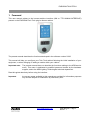
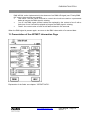
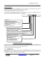
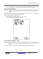
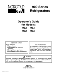
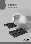
2. Description of the Unit
1
2
3
The user is provided with:
1 - A backlit LCD touch-screen enabling access to all menus
2 - A numeric keyboard
3 - A navigation/validation pushbutton - wheel
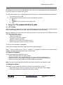
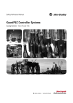
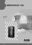
When the right-hand side door of the cabinet is opened, the rear of the Unit gives access to the
following:
3
2
4
1
1 - An opening on the rear face to activate the software reset button (in the event that the
touch screen becomes blocked)
2 - An opening in the side face for insertion of the SD memory card
3 - A connector to link up to the Twin Tech cabinet Controller units.
4 - A contrast potentiometer and a brightness potentiometer for the LCD touch-screen
www.adblighting.com
User Manual - Page 4
Issue 1.1
EURODIM TWIN TECH
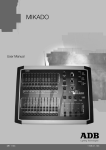
An original memory card is provided with the Unit. The Unit and its interface are not operational as
long as the card is not inserted into its slot.
The SD memory card can be changed by another SD memory card if the conditions are respected:
1 - The maximum size is 2GB
2 - You can copy the following files from de origin card to new card:
EDTT1
EDTT2
TRANSLAT (if it is present on the origin card)
Help
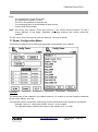
3. Using the TTD HUMAN INTERFACE (HMI)
3.1 LCD Display
When the cabinet is activated, an initial home page appears on the LCD display, allowing access
to the “Cabinet diagnostic” screen page, which is considered as the main screen.
Manually pressing the touch-zones on the main screen or the screens of the different menus
generally enables the user to:
Edit a field to be filled in,
Validate the said field,
Increment or decrement a value,
Validate or cancel a function,
Display one of the different available menus,
Return to the main screen or the list of menus.
The key or zone selected is highlighted.
There is no recording confirmation when the screen page is changed.
When a field is edited and its value is modified, it is possible to cancel its recording before
validation by pressing another touch-zone on the screen.
3.2 Numeric Keyboard
The numeric keyboard enables the user to:
- Add a field‟s value when the field is edited,
- Increment a field‟s value (by pressing key 1) or decrement (by pressing key 0),
- Directly access a screen page: next page using key 1; previous page using key 0;
- Enter the access code in order to access the different user levels.
Note: Any value entered that is beyond the user range is limited to the maximum value.
3.3 Navigation Wheel
The wheel may be handled by rotating clockwise or anti-clockwise in order to:
Select a field from a menu or choose a menu from the two menu screen pages,
Cancel the validation of a field when the latter is edited.
www.adblighting.com
User Manual - Page 5
Issue 1.1
EURODIM TWIN TECH
Pressing the navigation wheel enables the user to:
Edit a field to be filled in,
Validate the highlighted field,
Validate or cancel a function,
Select a menu or function.
4. Accessing the TTD HUMAN INTERFACE (HMI)
There are several possible user access levels. The first two screens (home and main screen) are
accessible to all users.
An access code needs to be entered in order to access the “Menu” screen. Depending on the
authorised access level, the user will be able to make modifications or launch functions.
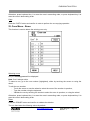
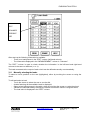
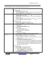
The table below indicates the functions accessible to the user according to the access level:
Function/menu
View the parameters
Edit the patch
Test a dimmer
Alter the settings
Scan the loads
Edit the laws and
multiplying factor
Edit the ARTNET
parameters
Manage the Cues
Load/Save the
parameters
Manually
synchronise
between controllers
ADB service
Level 0
Level 1
Level 2
Level 3
Code 5555
Code 6666
Code 7777
Code 8888
No
No
No
No
No
No
Yes
No
No
No
No
No
Yes
Yes
Yes
Yes
No
No
Yes
Yes
Yes
Yes
Yes
Yes
No
No
Yes
Yes
No
No
No
No
Yes
No
Yes
Yes
No
No
No
Yes
No
No
No
No
Level 0 does not allow access to any menu or function.
Depending on the authorised access level, certain functions or menus remain blocked. Should you
attempt to access these, the software will ask you to enter the access code for the next level in
order to authorise access to the function or menu.
The access-level indication can be viewed on all the screen pages. It is located in the top righthand corner and is signalled by a figure representing the current access level (from 0 to 3),
followed by a key symbol.
www.adblighting.com
User Manual - Page 6
Issue 1.1
EURODIM TWIN TECH
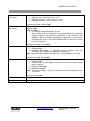
5. Screensaver
If whilst accessing a screen page other than the home page, the user does not handle the touchscreen, keyboard or wheel for a period of more than one minute, the software returns to the home
page. The access code will become 0. To access the "Menu" screen pages, an access code will
again need to be entered.
6. Online Assistance
A "HELP" key is provided in the bottom right-hand corner of all of the screen pages, allowing
touch-access to a help function, relating to the page consulted.
Press the “BACK” touch-button to return to the screen page.
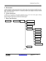
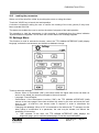
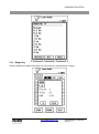
7. Menu Tree-Structure
Screensaver
Cabinet diagnosic
Menu 1
Patch A & B
Laws/M. Fact:
Power Conf.
Mem./DMX fail
Edit cue
Capture cue
Play cue
Copy cue
Erase cue
Prior/DMX fail
Play chaser
Settings
Cont. Menu 2
www.adblighting.com
User Manual - Page 7
Issue 1.1
EURODIM TWIN TECH
Menu 2
Scan loads
Learn
Scan
Mod.
measurements
mod.
Mod. Diag.
Artnet Patch
See Artnet
Artnet config.
ADB Service (functions
not described)
Synchronisation
8. Cabinet Configuration
The upper part of the Twin Tech cabinet may be equipped with:
Two Controller units,
or a Controller unit and a backup power supply module.
The Controller units, control all of the circuits (128 max.) constituting the modules available in the
cabinet (32 max.), according to the configuration recorded by the Unit software (patch) and the
channel values present on the DMX A, DMX B and ARTNET inputs (ETHERNET connection).
www.adblighting.com
User Manual - Page 8
Issue 1.1
EURODIM TWIN TECH
1
8.1 Synchronization
The human interface is synchronized continuously between two controllers (if present).
If two controllers are present, data from a controller (the one inserted into the slot from the top),
with the exception of the page "Diagnosis of the cabinet" or information from the selected controller
using the tabs "CTRL1" and "CTRL2".
If the controller 1 is a not functional, timing continues with the controller 2.
If the cabinet has only one controller all the information obtained from this controller
Note: Only the controller in slot from the top is able to detect modules in the cabinet (see Chapter
Power Configuration) and to report the status of sinewave and thyristor modules with full
diagnostic option (see section "Module Measuring" and "Diagnostic Modules")
If one controller is functional and inserted into the slot at the bottom, the cabinet will work
but the human interface will not be able to present the modules or diagnostic information
modules
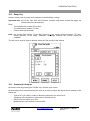
8.2 Module Control
The selector allows the Controller unit in service to be chosen. It may be set to position 1, A/R or 2.
When a controller is selected (1 or 2), the DMX A, DMX B and ARTNET signals present at this
controller‟s input are used.
The software configuration is HTP (Highest Take Precedence) by default. It is the highest value of
the DMX A, DMX B and ARTNET inputs (three available universes) and cue played and allocated
to a circuit that is taken into account in order to give the output dimming level.
www.adblighting.com
User Manual - Page 9
Issue 1.1
EURODIM TWIN TECH
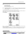
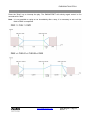
When the selector is set to A/R, the circuits of each module are controlled according to the
following rule: the highest value amongst the DMX A, DMX B and ARTNET inputs of the two
controllers is taken into account when controlling this circuit.
Example: Control using DMX A and DMX B inputs
DMX A
circuit 1=100%
DMX B
circuit 2= 0%
DMX A
circuit 1=90%
DMX B
circuit 2=100%
Controller 1
Circuit 1=100%
Circuit 2= 100%
Controller 2
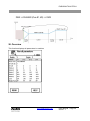
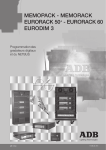
Notes: The PCB3031 board also enables:
the DMX A inputs to be connected between controllers (SW1, selectors 5 and 6 set to ON)
the DMX B inputs to be connected between controllers (SW1, selectors 7 and 8 set to ON)
PCB 3031 board
www.adblighting.com
User Manual - Page 10
Issue 1.1
EURODIM TWIN TECH
9. Cabinet Ventilation
The cabinet is ventilated by three fans arranged at the top of the cabinet, which extract hot air from
the cabinet. These fans can operate at two different extraction speeds (1 and 2).
The fans start on speed 1 (normal air extraction) if one of the circuits is controlled at above 50%
intensity. Below 50%, all the fans are idle.
Speed 2 is engaged (high air extraction) when a sinewave module and/or a module fitted with four
RCBO (MCB + RCD) is present in the cabinet and it is controlled. The speed 2 is also engaged if
the fans run in speed 1 and the temperature is too much high. The speed is held up to that
temperature is again acceptable*.
When the conditions described above are no longer met, the fans continue to operate for a further
five minutes at speed 1 before stopping.
10. Initial User Configuration
The identification of the modules present in the cabinet is controlled by the Controller 1.
This verification is automatic. A warning message signals any identification fault or error. See
Power Configuration menu in the event of an alarm.
The user must then:
Define or validate the control of each module‟s circuits by allocating the DMX channels. See
Patch, ARTNET Patch and ARTNET Configuration menus.
Define the laws and multiplying factor applicable on each of the circuits constituting a
module with respect to the loads that are wired at each circuit‟s output. These laws enable
each of the loads to be controlled correctly and risk-free (See Laws/Mult.Fact1. menu).
Define the type of modules to be used in order to dim the light by accepting the list of
modules identified by the controller (see power configuration menu)
10.1
Description of the Laws
The following laws are pre-recorded and available in the "Laws/Mult.Fact." menu: Linear, V120,
Fluo, Preheat, Square, Tv, BBC, Switch, Tv2, VRT, as well as six user defined laws enabling free
configuration by the user.
Important notes:
The user defined laws (1 to 6) are configured by default in order to apply the Linear law.
The six user laws are only editable via the optional TTD Management Software.
Switch law: presented in the form of a hysteresis, with a transition from 0 to 255 at 15% and
transition from 255 to 0 at 12% (see switch curve).
10.2
Applications of Laws on Specific Modules
10.2.1 Fluo Module (TTD/F*)
The first two outputs are used for the dimmer. The law of one‟s choice is applied here.
The last two outputs are used for the preheat: the switch law (ON/OFF) shall be used.
* The maximum ambient temperatures are defined in the EURODIM Twin Tech data sheet.
1
Mult Fact. = Multiplication Factor or Reduction of the maximum possible output level of a dimmer circuit.
www.adblighting.com
User Manual - Page 11
Issue 1.1
EURODIM TWIN TECH
10.2.2 Module DimSwitch with Dual filtering (TDD/HD*)
When the user chooses the switch law, the circuit is automatically configured with a filtering
characterised by a 200 µs rise time.
For all other laws, the circuit uses a filtering characterised by a 400 µs rise time.
The rise time is 400 µs by default.
Law curve giving the relationship between the DMX input (0 to 255) of the function law and the
output after application of the law in the same units.
www.adblighting.com
User Manual - Page 12
Issue 1.1
EURODIM TWIN TECH
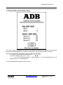
11. Presentation of the Home Page
This screen page is displayed as soon as the cabinet is switched on. It gives the information
concerning the start address for the DMX A and B inputs and the three ARTNET universes.
Information available for start address (valid for DMX and ARTNET):
"x": channel value to address cabinet output 1, 1 < x < 512
"not used": channel value = 0 or > 512
"- - - - -": no circuit physically present in cabinet location 1, or circuit identification error in
cabinet location 1 or operating fault
To access the diagnostic page, press the arrow.
www.adblighting.com
User Manual - Page 13
Issue 1.1
EURODIM TWIN TECH
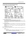
12. Presentation of the Cabinet Diagnostic Page
This screen shows the cabinet diagnostic information.
This page is divided into three zones:
A zone (CTRL1 or CRTL2 tab) providing information on the controllers,
A zone (EURODIM TT INFO) providing general information on the cabinet‟s operation,
identification of the modules by the controller and signalling the alarms,
A zone (INFO DMX) providing information on the DMX inputs and the functions associated
with these inputs.
Two keys enable the user to:
Access the two menu screen pages; MENU key. To access the Menu, when prompted by a
specific window the user access code needs to be entered using the keyboard, without
validating.
Access the ARTNET information; ENET key. This page is accessible regardless of the user
access level.
12.1
Controller (CTRL) Information
Note: The information is present if the controller is physically connected and operational in the
cabinet.
CTRL board active:
"Yes" if the controller is selected by the cabinet controller selector (position 1 for
controller 1 and position 2 for controller 2 or A/R for both),
"No" if the controller is not selected (circuits not controlled by this controller).
Frequency: displays the network frequency measured at the controller‟s input
www.adblighting.com
User Manual - Page 14
Issue 1.1
EURODIM TWIN TECH
Hardware/communication:
"OK" if the controller is operating correctly,
"Not OK" if a problem is detected. In this case, an error message and an exclamation
mark appear in the EURODIM TT INFO zone.
Software version: software version present in the controller
Temperature:
"OK" if the temperature measured in the controller is acceptable,
"Not OK" if the temperature measured in the controller is too much high. In this case,
the control value of all of the active circuits is reduced by 1% every minute until the
temperature measured becomes again acceptable* (also see paragraph on the
operation of the ventilation within the cabinet).
12.2
EURODIM Twin Tech Information
The first row of information available informs the user via a message that the cabinet and the
modules are in operation.
The message: "reference modules are used for dimming" indicates that all the modules installed in
the cabinet are identified by the software and enable the cabinet to operate normally.
An error message may be displayed instead.
In this case, press the exclamation mark to display a screen page, "Error list".
R, S, T phase: "OK" or "Not OK", checking the presence of the mains phases at the
controller,
Fan 1, 2, 3: "OK" or "not OK", checking the rotation of each fan arranged in the top of the
cabinet and ensuring air extraction,
Software version: software version present in the Human-Machine interface (TTD HUMAN
INTERFACE (HMI)) Unit.
When any problem is detected by the cabinet. An exclamation mark then appears to the right of the
screen page. In this case, press the exclamation mark to display a screen page, "Error list".
12.3
DMX Information
DMX A/B start address DMX A, DMX B channel value to address cabinet output 1
"x": 1 ≤ x ≤ 512
"not used": channel value = 0 or > 512
"- - - - -": no circuit physically present in cabinet location 1, or circuit identification error
in cabinet location 1 or operating fault.
DMX A/B present: Yes;
Yes: DMX signal reception detected
No: DMX signal reception missing.
Patch A/B (see "PATCH" menu):
Yes: the addressing filled-in in each patch at the circuits is not in ascending order,
No: the addressing filled-in in each patch at the circuits is in ascending order,
e.g. 1, 2, 3, 4, ..., 128 where 32 modules of four circuits are present in the cabinet.
* The maximum ambient temperatures are defined in EURODIM Twin Tech data sheet.
www.adblighting.com
User Manual - Page 15
Issue 1.1
EURODIM TWIN TECH
DMX A/B fail: action implemented in the absence of an DMX A/B signal (see "Priority/DMX
fail" menu), three actions are possible:
"last value": the last values received to control the circuits are used on a permanent
basis as long as the DMX signal is missing,
"cue 0:" the DMX signal channel values are replaced by the content of cue 0 with a
fade time of cue 0 and will be played as long as the DMX signal is missing,
"black": the control value of each circuit fades to black in five seconds.
When the DMX signal is present again, we return to the DMX values with a five-second fade.
13. Presentation of the ARTNET Information Page
Explanation of the fields: see chapter: "ARTNET INFO".
www.adblighting.com
User Manual - Page 16
Issue 1.1
EURODIM TWIN TECH
14. Description of the Menus
Two screen pages are available in order to choose a function, enabling the cabinet to be
configured using one of the following menus:
Patch: to edit patch A or B for each circuit
Laws/Mult.F: to choose the law used and the multiplying factor for each of the circuits
Conf. Power: to assign the modules used and detected in the 32 cabinet locations
Cues/DMX fail: cue management and action to be performed after a absence of
DMX/ARTNET
View all: overall view of all the parameters per module or per circuit
Test/Flash: to launch a test or the flash of a circuit
Load/Save: to save and load the parameters of the controllers and of each circuit
Settings: Human-Machine interface configuration
Scan loads: to measure/scan the loads connected at the outputs of each circuit
Mod. Meas.: gives the voltage and current measurements for each circuit
Mod. Diag.: gives the diagnosis of the outputs of each module
ARTNET patch: to edit the patch of the three ARTNET universes for each circuit
View ARTNET: general information on the ARTNET universes and the Ethernet connection
ARTNET set.: to configure the three ARTNET universes
ADB Service: function available to ADB technical service only
Synchro: to synchronise the parameters recorded between each of the controllers
www.adblighting.com
User Manual - Page 17
Issue 1.1
EURODIM TWIN TECH
Note:
All the information displayed in the different menus originates from controller 1 if two
controllers are present in the cabinet.
If only controller 2 is present, all the information displayed in the different menus will
originate from the latter. When changing the patch, power multiplication factor, law... the
new data is sent to each controller. The cirsuits defined as « empty slot » or « undefined
slot » are not editable and not visible in any screens. It appears again when the circuit will
not be declared as “empty slot” or “undefined slot”.
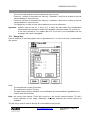
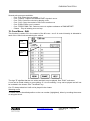
15. Patch Menu
This function is used to configure a patch on a circuit or set of circuits for the DMX A and DMX B
signal.
This configuration enables the user to attribute the value of a DMX A and DMX B signal channel to
the control of one of the cabinet‟s circuits.
Module
reference
DMX
channel
Reminder
The referencing of the modules in the cabinet starts at 1 in relation to the first location located at
the top of the cabinet, up to 32.
The left-hand column contains the referencing of the modules and circuits present in the cabinet.
The figure in the right-hand column is the channel attributed in the DMX signal.
Select patch A or B to start with
Use the wheel to rapidly move between all the rows of the patch. The row selected is highlighted.
To attribute a channel, position on a row and use:
www.adblighting.com
User Manual - Page 18
Issue 1.1
EURODIM TWIN TECH
The touch-screen and the numeric keyboard to enter a value,
Press key 1 directly to increment the value by 1 (between 1 and 512) in relation to the first
value available on a previous row,
Press key 0 directly to decrement the value by 1 (between 1 and 512) in relation to the first
value available on a previous row,
The Range key in order to enter values between two circuit references.
Important: Specific case for row 1/1: if key 0 or 1 is used, the value taken into consideration
corresponds to the content of output 128 if available, otherwise output 127, and so on.
If the value entered is 0 or greater than 512, the circuit is not controllable and the
message "Not used" is displayed.
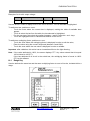
15.1
Range Key
Used to attribute an ascending patch value in graduations of 1 to a set of circuits, included within
one section.
Enter:
The start dimmer number (From dim),
The end dimmer number (To dim),
The start channel value to be taken into consideration for incrementation in graduations of 1,
Confirm with the OK button.
Note: the circuit's first number ("From dim") must be < the circuit‟s second number ("To dim")
during definition of the range. Otherwise, the range between two circuits cannot be
validated.
The ALL key is used in order to directly fill-in the cabinet‟s 128 circuits.
www.adblighting.com
User Manual - Page 19
Issue 1.1
EURODIM TWIN TECH
15.2
A ═> B Key
Used to copy all of the values from patch A to patch B and make them identical
16. Laws and Multiplying Factor Menu
This function is used to attribute a law and a multiplying factor to a circuit or set of circuits.
See explanation on the curves of the laws in a specific paragraph.
Reminder
The left-hand column contains the referencing of the modules and circuits present in the cabinet:
Example: Value 1/1: references module 1/circuit 1 of the module
The right-hand figure indicates the output on the cabinet (from 1 to 128).
In the Laws column we select the law that we wish to attribute to a circuit.
(This choice will depend on the type of load connected at the circuit output)
Important: after validation, this action has an immediate effect on the light dimming.
In the Multiplying Factor column, we attribute a multiplying factor (between 0 and 100%) to the
circuit.
Ultimately, the circuit control value is as follows:
DMX channel value law applied to the circuit multiplying factor.
www.adblighting.com
User Manual - Page 20
Issue 1.1
EURODIM TWIN TECH
Example of a circuit‟s output voltage:
Entry
DMX channel value (50%)
120 V law
Mult. fact.: 50%
230 V
115 V
57 V
29 V
Use the wheel in order to rapidly move to the row of a circuit. The row selected is highlighted.
To attribute a law, position on a row:
Touch the zone where the current law is displayed, making the table of available laws
appear,
Touch to select the law from the table; the law selected is highlighted,
For the user laws, first select the number (between 1 and 6) using the + and - keys
Touch the highlighted zone to validate and attribute to the circuit.
To attribute a multiplying factor, position on a row:
Touch the zone where the multiplying factor is displayed in order to edit the value,
Enter the value using the numeric keyboard (between 0 and 100%)
Touch the zone where the new value is displayed in order to validate.
Important: after validation, this action has an immediate effect on the light dimming.
Note: If the value attributed is 100%, the screen displays "FF". Any value entered that is beyond
100 is limited to 100 (FF).
If the law attributed to a circuit is the switch law, the multiplying factor is forced to 100%
(FF) by the software.
16.1
Range Key
Used to attribute the same law and the same multiplying factor to a set of circuits, included within a
range.
www.adblighting.com
User Manual - Page 21
Issue 1.1
EURODIM TWIN TECH
Enter:
The start dimmer number (From dim),
The end dimmer number (To dim),
The law to be attributed to these circuits,
The multiplying factor to be attributed to these circuits,
Confirm with the OK button.
Note: the circuit's first number ("From dim") must be < the circuit‟s second number ("To dim")
during definition of the range. Otherwise, the range between two circuits cannot be
validated.
The ALL key is used if we wish to enter the cabinet‟s 128 circuits directly.
17. Power Configuration Menu
This function configures the module type depending on its position in the cabinet.
Reminder
The referencing of the modules in the cabinet starts at 1 in relation to the first location situated at
the top of the cabinet, up to 32.
The left-hand column contains the referencing of the modules and circuits present in the cabinet:
Example: Value 1/1: references module 1/circuit 1 of the module
The right-hand figure indicates the output on the cabinet (from 1 to 128)
www.adblighting.com
User Manual - Page 22
Issue 1.1
EURODIM TWIN TECH
Module identification
All the modules are fitted with an EEPROM cue, which contains an ID code. When the modules are
installed in the cabinet, this ID is communicated to the controller.
This information is available in the "Present" column.
In this column, the following information can be obtained: a correct ID or "Undefined slot" for a
module that is unidentified by the controller or uninstalled.
TD4x3/MN/1R
TECHNOLOGY:
S (sinewave - standard with diagnostics only with 3R or 4R)
T (thyristor dimmer with 400µs rise time)
P (thyristor dimmer with 200µs rise time)
F (Fluo dimmer with 200µs and remote controlled preheat)
R (DimSwitch with 200µs rise time)
H(DimSwitch with dual 200µs/400µs rise time-standard
with diagnostics)
N (Non-Dim no remote control)
D (Full diagnostic version - optional)
Number of circuits in the module
Rated Load in kW of each circuit in the module
MN (MCB with 1P+N protection)
RCD protection: No RCD
1R (per module)
2R (2 individual protections - Fluo)
3R (3 individual protections)
4R (4 individual protections)
EURODIM TWIN TECH module identification table
In the Reference column, we are given the type of module that will actually be used by the
controller to control the circuits. This reference may be modified manually. If a position in the
cabinet is not used, the user must fill it in as an "undefined slot".
Use the wheel to view the ID of each module.
17.1
COMPARE Key
This function is used to compare the ID given in the PRESENT column and the ID given in the
REFERENCE column, for each module. This is used to check that the content of the references is
up-to-date with respect to the modules actually installed.
www.adblighting.com
User Manual - Page 23
Issue 1.1
EURODIM TWIN TECH
When the key is selected, two messages can be displayed:
"Ref. and present modules are identical": In this case, there is no module identification
problem,
"Ref. and present modules are different". The message also displays the number of
different modules. When the "OK" button is touched, the screen automatically displays the
first module where the ID is different. In this case, it is necessary to verify the identification
of the module physically present in the cabinet and, if necessary, modify the ID in the
"REFERENCE" column.
17.2 REF. PRES. Key
This function is used to copy the content of the IDs of the PRESENT column to the REFERENCE
column, for all the modules.
Attributing an ID
To attribute an ID to a module in the REFERENCE column, position on the module using the
wheel:
Touch the module zone, leading the module ID table to appear,
Touch to select a reference from the table; the reference selected is highlighted,
Touch the highlighted reference to validate and attribute to the module.
17.3 Range Key
Used to attribute the same ID to a set of modules, included within a range.
www.adblighting.com
User Manual - Page 24
Issue 1.1
EURODIM TWIN TECH
Enter:
Note:
The start module number,
The end module number,
The ID to be attributed to these modules,
Confirm with the OK button.
the module's first number ("From module") must be < the module‟s second number ("To
module") during definition of the range. Otherwise, the range between two modules
cannot be validated.
The ALL key is used in order to directly enter the cabinet's 32 modules.
A window opens when we exit the menu after a change has been made to a module‟s reference in
a given location. The user is invited to go to the patch menu, if necessary.
18. Cues Menu
80 cues + 1 emergency cue2 (cue no. 0) are available to record pre-defined circuit-control values.
These cues can be played.
A special (emergency) cue bearing the no. 0 is available to replace the circuit-control values in the
event that the DMX and/or ARTNET signals is not present. See "PRIOR/DMX FAIL" sub-menu
2
According to the human-interface hardware version installed on the cabinet, it is possible for only the
emergency cue (no. 0) to be available.
www.adblighting.com
User Manual - Page 25
Issue 1.1
EURODIM TWIN TECH
Several sub-menus are available:
Cue - Edit: Enter the cue content
Cue - Capture: Capture the DMX/ARTNET signals in a cue
Cue - Play: Control the circuits by playing a cue
Cue - Copy: Copy the content of one cue to another cue
Cue - Erase: Erase a cue‟s content
Cue - PRIOR. DMX FAIL: Select a source to replace a absence of DMX/ARTNET
Chaser - Play all existing cues on loop
19. Cues Menu - Edit
This function is used to fill in the content of the 80 cues + cue 0. A control intensity is allocated to
each of the 128 circuits constituting the cabinet.
Cue
number
Existing
cue
The sign "E" signifies that the cue exists and that it may be played. See "PLAY" sub-menu.
A cue can be made existing or non-existing. If it is non-existing, it may not be played and will not
be included in the chaser. See "Time/Exist" key.
Cue "0" always exists but it will not be played in the chaser.
Selecting a cue
To select a cue to be edited position on the cue number (highlighted), either by touching the screen
or using the wheel.
www.adblighting.com
User Manual - Page 26
Issue 1.1
EURODIM TWIN TECH
To edit the cue number:
Touch the screen or use the wheel to select the zone of the number in question,
Type the number using the keyboard,
Confirm the cue to be edited by touching the zone, or use the wheel.
Otherwise, press keyboard key 1 to scan the cues in ascending order, or press keyboard key 0 to
scan the cues in descending order.
Important: When a cue is edited, there is a loading time. The status row at the bottom of the page
informs the user of this status. Wait for the synchronisation to be complete in order to
obtain a correct reading of the intensities of each of the cue‟s circuits.
Attributing intensity
To attribute a control intensity, position on a row using the wheel:
Touch the zone where the intensity is displayed in order to edit the value,
Enter the value using the numeric keyboard (between 0 and 100%)
Touch the zone where the new value is displayed in order to validate.
To identically recopy the intensity of the preceding circuit, use keyboard key.
Note: If the value attributed is 100%, the screen displays FF. Any value entered that is beyond
100 is limited to 100.
Any value entered into a non-existing cue will render it existing.
The backup (validation) of the intensities is conducted upon leaving the cue or function.
19.1
Range Key
Used to attribute the same intensity to a set of circuits, included within a range.
www.adblighting.com
User Manual - Page 27
Issue 1.1
EURODIM TWIN TECH
Enter:
The start dimmer number (From dim),
The end dimmer number (To dim),
The intensity to be attributed to these circuits,
Confirm with the OK button
Note: the circuit's first number ("From dim") must be < the circuit‟s second number ("To dim")
during definition of the range. Otherwise, the range between two circuits cannot be
validated.
The ALL key is used in order to directly enter the 128 circuits of the cabinet.
19.2 Time/Exist Key
Used to attribute an intensity rise time for all of the circuits when a cue is played.
Used to attribute a wait time. This function will be used when the chaser is played. See "CHASER PLAY" sub-menu.
Used to render a cue existing or non-existing.
Enter:
The fade time (minutes, seconds),
The wait time (minutes, seconds),
The existence of the cue (select yes/no),
Confirm with the OK button.
Note: the maximum time taken into account for the minutes is limited to 99 minutes.
www.adblighting.com
User Manual - Page 28
Issue 1.1
EURODIM TWIN TECH
20. Cues Menu - Capture
Instead of entering the cues using the Editing function, this function is used to capture the highest
intensity of the sources present at the controller's input (DMX & ARTNET), this being the case for
each circuit, and to save it in a cue (from 0 to 80).
Selecting a cue
To select a cue, go to the cue number (highlighted), either by touching the screen or using the
wheel.
To edit the cue number:
Touch the screen or use the wheel to select the zone of the number in question,
Type the number using the keyboard,
Validate the cue by touching the screen to select the zone in question, or using the wheel.
Otherwise, press keyboard key 1 to scan the cues in ascending order, or press keyboard key 0 to
scan the cues in descending order.
Important: when a cue is edited, there is a loading time. The status row at the bottom of the page
informs the user of this status. Wait for the synchronisation to be complete in order to
obtain a correct reading of the intensities of each of the cue‟s circuits.
20.1
DMX/ARTNET Capture
Press the "CAPTURE" key to launch the memorisation operation. The values appear in the table
after a few seconds. The cue number is followed by an asterisk (*) to indicate that the captured
DMX/ARTNET values are displayed. Press the "SAVE" key to save the intensities in the cue
displayed. The cue becomes existing ("E").
www.adblighting.com
User Manual - Page 29
Issue 1.1
EURODIM TWIN TECH
21. Cues Menu - Play
This function is used to play an existing cue.
The fade time corresponds to the rise time defined in the "Cue–Edit" menu.
Selecting a cue
Only the existing cues will be displayed. ("E")
To select a cue, position on the cue number (highlighted), either by touching the screen or using
the wheel.
To edit the cue number:
Touch the screen or use the wheel to select the zone of the number in question,
Type the number using the keyboard,
Validate the cue by touching the screen to select the zone in question, or using the wheel.
Otherwise, press keyboard key 1 to scan the cues in ascending order, or press keyboard key 0 to
scan the cues in descending order.
Play a cue
Press the "Play" key to launch the cue.
The information in this status lets you know the progress of memory fade:
"Fade to cue x": progressive rise to the nominal control intensity of each circuit,
"Cue played x": the fade is completed; the memory is played with current output values.
www.adblighting.com
User Manual - Page 30
Issue 1.1
EURODIM TWIN TECH
Press the "Stop" key to interrupt the play. The DMX/ARTNET will entirely regain control in five
seconds with a fade.
Note: It is not possible to replay a cue immediately after a stop, it is necessary to wait until the
fade to DMX is completed.
www.adblighting.com
User Manual - Page 31
Issue 1.1
EURODIM TWIN TECH
22. Cues Menu - Copy
This function is used to copy an existing cue to any other cue (existing or not).
Existing
source cue
destination cue
indication
Selecting the original cue
The field memory source can only display existing memories.
Note: Cue 0 always exists.
To select a cue, position on the cue number (highlighted), either by touching the screen or using
the wheel.
To edit the cue number:
Touch the screen or use the wheel to select the zone of the number in question,
Type the number using the keyboard,
Validate the cue by touching the screen to select the zone in question, or using the wheel.
Otherwise, press keyboard key 1 to scan the cues in ascending order, or press keyboard key 0 to
scan the cues in descending order.
Selecting the destination cue
Each of the cues may be overwritten.
To select a cue, position on the cue number (highlighted), either by touching the screen or using
the wheel.
To edit the cue number:
Touch the screen or use the wheel to select the zone of the number in question,
Type the number using the keyboard,
Validate the cue by touching the screen to select the zone in question, or using the wheel.
www.adblighting.com
User Manual - Page 32
Issue 1.1
EURODIM TWIN TECH
Otherwise, press keyboard key 1 to scan the cues in ascending order, or press keyboard key 0 to
scan the cues in descending order.
Copy
Press the 'COPY' button and confirm in order to perform the cue copying operation.
23. Cues Menu - Erase
This function is used to delete the existing cues only.
Selecting a cue
Only the existing cues will be displayed.
Note: Cue 0 always exists.
To select a cue, go to the cue number (highlighted), either by touching the screen or using the
wheel.
To edit the cue number:
Touch the screen or use the wheel to select the zone of the number in question,
Type the number using the keyboard,
Validate the cue by touching the screen to select the zone in question, or using the wheel.
Otherwise, press keyboard key 1 to scan the cues in ascending order, or press keyboard key 0 to
scan the cues in descending order.
Erase
Press the „ERASE‟ button and confirm to validate the deletion.
The cue then takes the following values by default:
www.adblighting.com
User Manual - Page 33
Issue 1.1
EURODIM TWIN TECH
Note:
Intensity: 0%
Fade time: 0 min 5 sec
Wait time: 0 min 5 sec
Cue exists: No
Cue 0 may be deleted (i.e. filled in with the default parameters) but it will continue to exist.
Intensity: 0%
Fade time: 0 min 5 sec
Wait time: 0 min 5 sec
Cue exists: YES
24. Cues Menu - Priority/DMX fail
This function is used to prioritise the selection amongst the DMX/ARTNET inputs and cue played,
and also to replace a missing source.
Priority to
the
highest
value
present
24.1
The DMX/ARTNET
values are no
longer taken into
consideration in the
priority
Priority
When memory is performed using the "play memory", the DMX / ARTNET can be hidden by
selecting "DMX MASK" or if the highest value between memory and DMX / ARTNET shall be
taken, select HTP.
24.2
DMX/ARTNET fail
In case of DMX or ARTNET signals is not present or failure, the latest values are kept for 10
seconds. After that the source is replaced by one of three options:
The last control value received from the source that has disappeared,
Control by cue 0 with fade (rise time of cue 0),
0% control (black) with fade in five seconds.
www.adblighting.com
User Manual - Page 34
Issue 1.1
EURODIM TWIN TECH
Example with the Memory 0 with the circuit 1 at 95%
DMX A circuit 1=100%
Memory 0 circuit 1=95%
Controller 1
DMX B circuit 2= 0%
DMX A circuit 1=90%
Circuit 1=95%
Circuit 2= 100%
Controller 2
DMX B circuit 2=100%
Select one of the possibilities by touching one of the keys.
25. Cues Menu – Play Chaser
This function is used to link up the play of all existent cues, except cue 0.
The list of cues played is displayed in the window.
Press the "PLAY" key to launch the chaser. The cues are played in ascending order.
Press the "Stop" key to interrupt the chaser. The DMX/ARTNET signals once more control the
circuits.
The chaser may not be replayed immediately after a stop. It is necessary to wait for five seconds
before the chaser can be launched again.
www.adblighting.com
User Manual - Page 35
Issue 1.1
EURODIM TWIN TECH
26. Overview
This function displays all parameters in modules
www.adblighting.com
User Manual - Page 36
Issue 1.1
EURODIM TWIN TECH
Parameters displayed are:
Power info: the type of module used by the controllers.
Circuit qty.: Number of circuit in the module.
Circuit: position of the circuit taking into account the number of circuit in the previous
modules.
Patch A, B refers to the DMX patch for A and B.
Patch C, D, E: refers to the patch for Artnet universe 1, 2, 3.
Laws: laws applied to this circuit.
Multipl. Fact. : Multiplying factor applied to the circuit.
Note: If a module contains less than four circuits, the circuits will be displayed with empty "------"
to indicate that there is not physically present in the circuit module.
Selection of modules and outputs.
To select a module or an output, position the cursor on the number of the module or the output
(highlighted), either by touchscreen or use of the dial.
To view the settings of the module:
- Touch the screen on the area of the number or use the wheel,
- Type the number on the keypad,
- Confirm the number by pressing on the touch sensitive area or using the dial.
Otherwise, press 1 to scan the keypad modules or outputs in ascending order or press the 0 key
on the keyboard to scan the modules or the output in descending order.
The field module and output are related, that is to say that if you manually change the field or
output module to the other will automatically update.
www.adblighting.com
User Manual - Page 37
Issue 1.1
EURODIM TWIN TECH
27. Test and Flash Menu
This menu is used to test the outputs of each circuit via a command from controller 1 or 2.
Output/patch
relationship
In order to be able to control a circuit (output) or a set of circuits with respect to controller 1 or 2 (if
present), verify the position of the cabinet selector in order to ensure that it matches the control by
the controller selected on the screen.
Select the controller that is to control the output to be tested, touch-key "CTRL 1" or "CTRL 2".
Note: When a test or a flash is launched, the DMX/ARTNET are cut off.
27.1
Test Tab
Touch to select the test tab.
Used to control a circuit with constant intensity.
To select an output, position on the output number (highlighted), either by touching the screen or
using the wheel.
To edit the output number:
Touch the screen to select the output number or use the wheel,
Type the number using the keyboard,
Validate the output by touching the screen to select the zone in question, or using the wheel.
Otherwise, press keyboard key 1 (or the + key on the screen) to increment the output number or
press keyboard key 0 (or the - key on the screen) to decrement the output number.
According to the output function selected, the - value of corresponding patches A and B is
displayed.
Adjust, in the same manner:
the output control intensity, value row, intensity between 0 and 100% (FF)
www.adblighting.com
User Manual - Page 38
Issue 1.1
EURODIM TWIN TECH
the output control duration, delay row, duration between 0 ( ~ 0.5 secs) and 60 secs
Touch the screen or use the wheel to select either the manual or automated test.
Manual test: only the selected output associated with a reference module will be controlled with the
set intensity.
Automated test: all outputs starting from the selected output will be tested one after the other for
the duration and with the set intensity except the channels defined as “undefined slot” or “Empty
slot”.
Press the "START" key to launch the manual or automated cycle.
Press the same "START" key to stop the manual or automated cycle.
27.2
Flash Tab
Touch to select the Flash tab.
Used to control a circuit with automated variation of the intensity between 0 and the set value.
To select an output, position on the output number (highlighted), either by touching the screen or
using the wheel.
To edit the output number:
Touch the screen to select the output number or use the wheel,
Type the number using the keyboard,
Validate the output by touching the screen to select the zone in question, or using the
wheel.
Otherwise, press keyboard key 1 (or the + key on the screen) to increment the output number or
press keyboard key 0 (or the - key on the screen) to decrement the output number.
According to the output function selected, the - value of corresponding patches A and B is
displayed.
Adjust, in the same manner:
the output control intensity, value row, intensity between 0 and 100% (FF)
the output control duration, delay row, duration between 0 ( ~ 0.5 secs) and 60 secs
Touch the screen or use the wheel to select either the manual or automated test.
Manual test: only the selected output will be controlled with automated variation of the intensity.
Automated test: all outputs starting from the selected output will be tested one after the other
throughout the duration and with variation of the intensity except the channels defined as
“undefined slot” or “Empty slot”.
Press the "START" key to launch the manual or automated cycle.
Press the same "START" key to stop the manual or automated cycle.
28. Load/Save Menu
This function is used to save or load the parameters of the cabinet, such as patch A & B, the
multiplying factor, the laws and the power configuration. Furthermore, it is possible to choose to
save the 80+1 cues upon confirmation.
www.adblighting.com
User Manual - Page 39
Issue 1.1
EURODIM TWIN TECH
In order to conduct a save (backup) or load operation, the SD card must be present in the slot
planned in the TTD HUMAN INTERFACE (HMI) Unit, located behind the right contractors door.
If no card is detected, the status row displays "No card detected".
The "List" key is used to reread the content of the backup files present on the SD card.
There are ten locations available on the card in order to conduct backups.
Each file saved is recorded in the following form:
EDTT-01 (02, 03, …), gives the file name,
V3, backup version,
With cue or without cue with backup or without backup of the cues in the file,
18/02/11: date of manual recording of the backup.
28.1
Saving the parameters
Select one of the ten locations in which to save, either by touching the screen or using the wheel.
We can position on an existent file. In this case, the file is overwritten during the save (without a
confirmation request)
Touch the "SAVE" key to launch the save.
A first window requests the save date to be manually recorded. After validation, a second window
requests confirmation of the save cue execution (yes/no). Next, a third window requests the user‟s
confirmation of the save operation configured as described.
The status row enables the user to monitor the state of progress of the save operation.
www.adblighting.com
User Manual - Page 40
Issue 1.1
EURODIM TWIN TECH
28.2
Loading the parameters
Select one of the save files, either by touching the screen or using the wheel.
Touch the "LOAD" key to launch the load operation.
A window is displayed, asking the user to confirm the loading of the cues (yes/no) if they have
been recorded in the file.
The status row enables the user to monitor the state of progress of the load operation.
The operation to load the parameters to the controller is completed when the status indicates
“Synchronisation completed”, do not leave the function before the message appears.
29. Settings Menu
This function is used to activate the buzzer, select the TTD HUMAN INTERFACE (HMI) display
language, activate the screensaver and indicate a database change.
Touch to select the settings:
Buzzer: When it is activated ("ON"), the buzzer emits the signal when there has been an
action on the wheel, the numeric touchpad or the touch-screen,
Language: French/English,
Screensaver: If the screensaver is active ("ON"), the TTD HUMAN INTERFACE (HMI)
returns to the home page if there has not been any action by the user and resets the user
level to zero. A level-four user access code is required in order to deactivate the
screensaver,
Changing the database: When a PC is connected to the cabinet with TT manager and the
latter makes a modification to a parameter, the user may be alerted, but without the
possibility of intervening:
"ON" selected: in this case, the TTD HUMAN INTERFACE (HMI) displays the
diagnostic page, opens a window and displays "Controller synchronisation",
www.adblighting.com
User Manual - Page 41
Issue 1.1
EURODIM TWIN TECH
"OFF" selected: the modifications are made but the screen is not changed.
30. Load Scanning Menu
Important: This function can only be used if the sequential diagnostic kit has been installed in the
cabinet, it being used to measure the neutral current on the module power line
(busbar).
This function is used to scan the loads present at the output of each circuit and check that the
loads have not changed with respect to a previous state.
This verification is performed in two stages:
Learn: to define the reference loads present at the output,
Scan: to launch the load verification operation.
31. Load Scanning Menu - Learn
Important: This function can only be used if the sequential diagnostic kit has been installed in the
cabinet, it being used to measure the neutral current on the module power line
(busbar).
This function is used to define the reference loads present at the output of each circuit.
www.adblighting.com
User Manual - Page 42
Issue 1.1
EURODIM TWIN TECH
Possibilities:
EDIT
SCANNED
PRESENT
REF
After start up the following information is available:
There is no load present in the "EDIT" column (left-hand column),
The information displayed in the "MEASUREMENT" column is "unknown".
The "DIFF." column is used to check whether the information in the left-hand and right-hand
columns is the same or different (= or ≠).
The load connected at the output of each circuit can be defined manually or automatically.
31.1
Manually selecting the loads
To select a circuit, position on the row (highlighted), either by touching the screen or using the
wheel.
To edit and select a load:
Touch the screen to select the row or use the dial,
A table featuring all the available loads is displayed,
Select a load value present in the table, either by touching the screen or using the wheel,
Validate the selected load by touching the screen to select the value or using the wheel,
The load value is displayed in the "EDIT" column.
www.adblighting.com
User Manual - Page 43
Issue 1.1
EURODIM TWIN TECH
31.2
Range Key
Used to attribute the same load value to a set of circuits, included within a range.
www.adblighting.com
User Manual - Page 44
Issue 1.1
EURODIM TWIN TECH
Enter:
The start dimmer number (From dim),
The end dimmer number (To dim),
The load to be attributed to these circuits (a table appears enabling the load to be selected,
see manual load selection),
Confirm with the OK button.
Note: the circuit's first number ("From dim") must be < the circuit‟s second number ("To dim")
during definition of the range. Otherwise, the range between two circuits cannot be
validated.
The ALL key is used in order to directly enter the 128 circuits of the cabinet.
31.3
Automatically selecting the loads
Press the "AUTOMATIC" key; three options are available:
Measurement: the load information available in the "Measurement" column of all the circuits
is recopied to the "EDIT” column. After copying, the name of the left-hand column changes
and becomes "SCANNED",
Present: the information originating from the PRESENT column (see Power Configuration
menu) are recopied into the "EDIT" column. After copying, the name of the left-hand
column changes and becomes "PRESENT",
Reference: the information originating from the REFERENCE column (see Power
Configuration menu) are recopied into the "EDIT" column. After copying, the name of the
left-hand column changes and becomes "REFERENCE",
Select one of the options, either by touching the screen or using the wheel and confirm the choice.
Note: for the options PRESENT and REFERENCE, the column is updated automatically based on
what was defined in "conf.puiss."
Automatic selection: Reference
www.adblighting.com
User Manual - Page 45
Issue 1.1
EURODIM TWIN TECH
32. Loads Scanning Menu - Scan
Important: this function is only accessible if the sequential diagnostic kit has been installed in the
cabinet. In effect, it is used to measure the neutral current on the module power line
(busbar).
This function is used to launch a test verify the loads present at the output of each circuit using a
current measurement in relation to the loads provided by the "Load verification – Learn" menu.
Manual
selection = √
32.1
Selecting the outputs to be scanned
There are several ways to manually select the outputs that we wish to scan:
By touching the module/dimmer number,
By selecting the row using the wheel by pressing down,
By positioning on the row using the wheel and by pressing key 1 to select (press key 0 to
deselect)
A validation symbol appears in front of the module/dimmer number.
Important note: It is not possible to select a sinewave or FLUO module circuit for the scan (see
status).
A circuit cannot be selected if the switch law is applied (see information in Status)
because in this case, this circuit‟s load is not dimmable
A circuit cannot be selected if it is defined as "Non dim" (see information in
Status) because in this case, this type of module does not enable dimming
www.adblighting.com
User Manual - Page 46
Issue 1.1
EURODIM TWIN TECH
32.2
Range Key
Used to select a set of circuits to be scanned, included within a range.
Important note: the FLUO, Non Dim and sinewave modules and those circuits that apply the
switch law will not be selected.
Enter:
The start dimmer number (From dim),
The end dimmer number (To dim),
Confirm with the OK button.
Note: the circuit's first number ("From dim") must be < the circuit‟s second number ("To dim")
during definition of the range. Otherwise, the range between two circuits cannot be
validated.
The ALL key is used in order to directly select the 128 circuits of the cabinet.
32.3
Scanning the Outputs
Launch the scan by pressing the "SCAN" key. Confirm your choice.
Several stages are conducted during the scan of a circuit‟s output and which can be viewed on the
status row:
Test at 14% (of 230V) in order to detect the presence of a short circuit
(Stopping of the procedure in the event of a short-circuit).
Dimming of the output up to 50%
Measurement of the neutral current at 50%
www.adblighting.com
User Manual - Page 47
Issue 1.1
EURODIM TWIN TECH
Important note: The scan can only be conducted if there is no sinewave module present in the
cabinet, even if it is not selected for the scan. The sinewave modules need to be
removed from the cabinet before launching the scan
The result of the measurement appears in the "MEASUREMENT" column.
The following information can be found:
Load value,
No load,
Overload,
There is an overload if:
for a module of 3KW, a load > 4KW has been measured,
for a module of 5KW, a load > 7KW has been measured,
The circuit currently being scanned is automatically highlighted. This function vanishes as soon as
you use the dial or select another output on the touchscreen. To find this function, press the
number “6” on the numerical keyboard.
When the load scan is completed, we can verify the differences in the table between the modules
recorded (left-hand column) and the load values measured (right-hand column). The ≠ sign
appears in the central column in the event of an inconsistency.
33. Module Measurements Menu
This function displays the values measured for the sinewave and thyristor modules with a fulldiagnostic option
Only the sinewave or thyristor/fluo modules with full-diagnostic option can give measurements or
diagnostic. The fluo and thyristor modules without this diagnosis will always give N/A (not
available).
www.adblighting.com
User Manual - Page 48
Issue 1.1
EURODIM TWIN TECH
Information displayed according to the module type:
circuit technology
Sinewave, thyristor, fluo with or without diagnosis
input V
voltage measured at the module input (identical information for the four
circuits); Voltage in V
output V
Voltage measured at the output of each circuit; Sinewave module: always N/A
output I
Output current per circuit.
Controller vers.
Sinewave and Thyristor modules with Diag: measurement (A) accurate to one
decimal point
Module software version
Controller sec. vers.
Indication available only for sinewave modules
33.1
Selecting the modules and circuits
To select a module or circuit, position on the module or dimmer number (highlighted), either by
touching the screen or using the wheel.
To display the module or circuit measurements:
Touch the zone of the number or use the wheel,
Type the number using the keyboard,
Validate the number by touching the screen to select the zone in question, or using the
wheel.
Otherwise, press keyboard key 1 to scan the modules (circuits) in ascending order, or press
keyboard key 0 to scan the modules (circuits) in descending order.
34. Modules Diagnosis Menu
This menu is used to verify the operation of the modules and obtain detailed information on the
operation of each circuit. It is useful in the event that an error is detected and displayed in the
diagnostic screen page.
www.adblighting.com
User Manual - Page 49
Issue 1.1
EURODIM TWIN TECH
34.1
Selecting the modules and circuits
To select a module or circuit, position on the module or dimmer number (highlighted), either by
touching the screen or using the wheel.
To display the module or circuit measurements:
Touch the screen to select the zone of the number in question, or use the wheel,
Type the number using the keyboard,
Validate the number by touching the screen to select the zone in question, or using the
wheel.
Otherwise, press keyboard key 1 to scan the modules (circuits) in ascending order, or press
keyboard key 0 to scan the modules (circuits) in descending order.
The first frame provides a summary of the functional status of each of the circuits constituting the
"OK" or "Not OK" module. In the event of a problem detected on a circuit, display the circuit to
obtain more details on the malfunction.
The second frame is the detail for each of the circuits constituting the module.
www.adblighting.com
User Manual - Page 50
Issue 1.1
EURODIM TWIN TECH
Information displayed for each circuit, according to the module type:
Thyristor (per circuit)
Breaker (per circuit)
Load (per circuit)
Overloads
(per circuit)
Sinewave: always "N/A"
Thyristor with Diag:
1 - Displays "OK" if everything is fine
2 - Displays "Damaged": if a voltage > 210 V is measured whereas the
control measured by the module is < 25 %
Sinewave:
1 - Displays "N/A" if the control value is < 17 % or the circuit is
overloaded or short-circuited
2 - Displays "OK" if the control value is > 17 % and not overloaded or
short-circuited
3 - Displays "triggered" if the control value is control > 17 % and no
output voltage is measured on the circuit
Thyristor (per circuit):
1 - Displays "OK" if the breaker is engaged
2 - Displays "disengaged" if the breaker has blown
Sinewave & Thyristor with diag:
1 - Displays "N/A":
The control is set to zero
and/or the output voltage is too low
2 - Displays "NO":
If the control value is > 0
The output voltage is measured
and the current is not measured
3 - Displays "YES"
If the control is present
And the output voltage and the output current is measured
Sinewave:
1 - Displays "light": if the voltage is > 13 A for 30 secs
2 - Displays "medium": if the current is > 16 A for 10 secs
Here, the control decreases every 500 ms until the current
reaches < 13 A
3 - Displays "Severe": if the current is > 20 A for 1 sec
The control is automatically set to zero
After 2 mins, an actual control test is repeated and if the overload
is "severe" again, a second test is conducted. If the overload is
still severe, a status message is displayed at the bottom of the
screen, requesting the user to set all the DMX/ARTNET inputs of
the circuit to zero for 30 secs.
Thyristor with diag.:
1 - Displays “N/A” if the breaker has blown
2 - Displays "YES” if the breaker is OK and:
If the load is > 3.5KW (for a 3kW module)
if the load > 5.5.5KW (for a 5kW module)
if the load is > 11KW (for a 10kW module)
3 - Displays "NO" in all other cases
www.adblighting.com
User Manual - Page 51
Issue 1.1
EURODIM TWIN TECH
OverCurrent
(per circuit)
Short-circuit
(per circuit)
Temperature
Main voltage
Sinewave:
Displays “low”: if the current is > 13 A
Displays "average": if the current is > 16 A
Displays "Severe": if the current is > 20 A
Thyristor with diag.: always "N/A"
Sinewave:
Displays "NO"
Displays "YES":
The control is automatically set to zero
After 2 mins, an actual control test is repeated and if the overload is
"severe" again, a second test is conducted. If the overload is still
severe, a status message is displayed at the bottom of the screen,
requesting the user to set all the DMX/ARTNET inputs of the circuit
to zero for 30 secs.
Thyristor with diag.: always N/A
Sinewave:
1 - Displays "OK"
2 - Displays “too high” => automatic control reduction until the
temperature now longer exceeds the threshold set
Note: The measure be different between the ½ circuits and the ¾ circuits
Thyristor with diag.: always N/A
Sinewave:
1 - Displays "OK"
Cases 2 and 3 do not trigger a module error as it is the main voltage
that is incorrect
2 - Displays "Too high"
3 - Displays “too low”
Note: If the main voltage < 205 V, the sinewave module no longer controls
its circuits
Controller vers.
Thyristor: always N/A
Module software version
Sec. vers. Controller
Indication available only for sinewave modules
www.adblighting.com
User Manual - Page 52
Issue 1.1
EURODIM TWIN TECH
35.
ARTNET Patch Menu
This function is used to configure a patch on a circuit or a set of circuits for each of universes 1, 2
and 3.
This configuration is used to attribute the value of a channel of each universe to the control of a
circuit of the cabinet.
Module
reference
Universe
channel
Reminder
The referencing of the modules in the cabinet starts at 1 in relation to the first location situated at
the top of the cabinet, up to 32.
The left-hand column contains the referencing of the modules and circuits present in the cabinet:
Example: Value 1/1: references module 1/circuit 1 of the module
The right-hand figure indicates the output on the cabinet (from 1 to 128).
The channel attributed for each universe is given in the right-hand column.
Start by selecting universe 1, 2 or 3.
Use the wheel to rapidly move between all the rows of the patch. The row selected is highlighted.
To attribute a channel, position on a row and use:
The touch-screen and the numeric keyboard to enter a value,
Press key 1 directly to increment the value by 1 (between 1 and 512) in relation to the first
value available on a previous row,
Press key 0 directly to decrement the value by 1 (between 1 and 512) in relation to the first
value available on a previous row,
The Range key in order to enter values between two circuit references.
www.adblighting.com
User Manual - Page 53
Issue 1.1
EURODIM TWIN TECH
Important: Specific case for row 1/1: If key 0 or 1 is used, the value taken into consideration
corresponds to the content of output 128 if available, otherwise to output 127, and so
on.
If the value entered is 0 or greater than 512, the circuit cannot be coordinated and the
message “Not used” is displayed.
35.1
Range Key
Used to attribute an ascending patch value in graduations of 1 to a set of circuits, included within a
range.
Enter:
The start dimmer number (From dim),
The end dimmer number (To dim),
The start channel value to be taken into consideration for the increment in steps of 1
Confirm with the OK button.
Note: the circuit's first number ("From dim") must be < the circuit‟s second number ("To dim")
during definition of the range. Otherwise, the range between two circuits cannot be
validated.
The ALL key is used in order to directly enter the 128 circuits of the cabinet.
www.adblighting.com
User Manual - Page 54
Issue 1.1
EURODIM TWIN TECH
36.
ARTNET Info Menu
These two screens show the status of the ARTNET connections, the configuration information for
the three universes managed by each controller, as well as the IP addresses entered at each
controller.
This page is divided into two zones:
A zone (CTRL1 or CRTL2 key) providing information on the status of the universes and
their configurations for each controller,
A zone (ENET) providing the IP addresses entered for each controller.
Note: Only the "ARTNET present/missing" information depends on the controller.
In effect, each controller has its own ARTNET input. The back button, called "MENU" or
"DIAG" is used to return to the previous screen.
36.1
ARTNET Information
For each of the three universes (1, 2, 3), the following information is available:
Present:
"Yes": detection of the Ethernet frame corresponding to the universe,
"No": no reception of the Ethernet frame corresponding to the universe.
Used: see "ARTNET Configuration" menu
"yes": the universe values are taken into consideration for the control of the circuits
"no": the universe values are not taken into consideration for the control of the circuits
Fail: action implemented in the absence of the universe (see “Priority/DMX fail” menu),
three actions are possible:
www.adblighting.com
User Manual - Page 55
Issue 1.1
EURODIM TWIN TECH
"last value": the last values received to control the circuits are used permanently as
long as the universe is missing,
"cue" 0: the values of the universe channels are replaced by the content of cue 0 and
will be played as long as the universe is missing,
"black": the control value of each circuit fades to zero intensity (black) in 5 seconds.
When the universe is present once more, a fade is launched to the intensities given by
ARTNET in a time of 5 seconds.
When the universe is present once more, a fade is launched to the intensities given by ARTNET in
a time of 5 seconds.
start addr.: value of the universe channel to address cabinet output 1, see "ARTNET
PATCH" menu
"x": 1 ≤ x ≤ 512
"not used": channel value = 0 or > 512
"- - - - -": no circuit physically present in cabinet location 1, or circuit identification error
in cabinet location 1 or operating fault.
Patch: see "ARTNET PATCH" menu,
Yes: the addressing entered in each patch at the circuits is not in ascending order,
No: the addressing entered in each patch at the circuits is in ascending order, e.g. 1, 2,
3, 4,…., 128 in the case where 32 modules are present in the cabinet.
Subnet: value between 0 and 15, see "ARTNET config" menu
Port: value between 0 and 15, see "ARTNET config" menu
Note: When the ARTNET entries are controlled by an ISIS rotating ADB console, all the subnets
must have the same number.
Ethernet Information
The IP address of each controller and the value of the sub-network mask are given.
Important: the IP addresses of each controller must be different. If this is not the case, it is
imperative to address the ADB technical department.
37. ARTNET Configuration Menu
This function configures the ARTNET universes for the two controllers as well as the subnet and
port values.
www.adblighting.com
User Manual - Page 56
Issue 1.1
EURODIM TWIN TECH
37.1
Selecting Universe Mode
For each universe, choose the operating mode:
“Not Used” mode: the universe is not taken into consideration for the control of the circuits,
“ARTNET” mode: the universe is taken into consideration for the control of the circuits.
Touch to select the mode. The mode selected must be highlighted.
37.2
Subnet and Universe Port
For each universe, fill-in the subnet and the port such that it is identical to the configuration of the
control console.
Subnet and port value: between 0 and 15.
Position on the subnet value (port), either by touching the screen or using the wheel. The value is
highlighted.
Type the value using the keyboard,
Validate the value by touching the screen to select the zone in question, or using the wheel.
38. Synchronisation Menu
This function is used to perform a copy operation between the controllers in the event that a new
CTRL (blank or containing old data) is put in place in the cabinet.
www.adblighting.com
User Manual - Page 57
Issue 1.1
EURODIM TWIN TECH
Data copied:
- Patch DMX & ARTNET,
- Laws,
- Cues,
- Modules used,
- Cue priority,
- ARTNET configuration,
- Load measurements,
- Action in the event of a absent source.
Touch one of the "SYNC" keys to launch the copy procedure between controllers, that is, from
controller 1 to controller 2 or vice versa.
A window opens and a confirmation request is requested.
During the copy operation, the Status row indicates the state of progress by displaying the
percentage copied.
When the copy operation is completed, the following information is displayed: “Synchronisation
completed”.
39. Managing the Alarms
The cabinet diagnostic page indicates any malfunctions of the cabinet with a warning message.
Example: "Choose the modules to be used".
An exclamation mark also appears. Touch the exclamation mark to display a screen page,
grouping together the errors list.
www.adblighting.com
User Manual - Page 58
Issue 1.1
EURODIM TWIN TECH
Warning
message
39.1
Errors List Screen Page
www.adblighting.com
User Manual - Page 59
Issue 1.1
EURODIM TWIN TECH
The two CTRL1 and CTRL2 keys are used to display the errors detected by each controller.
Indeed, each controller can display different errors, in the CTRL frame in particular.
Touch one of the two keys to display the error messages.
39.2
List of Errors displayed in the EURODIM Twin Tech Frame
1 - Displays an error on a mains phase: example: "phase r error". Explanation: the voltage
measured at the controller input is outside the operation range.
2 - Displays an error on a cabinet fan that is not functioning: example: "error FAN 1".
39.3
List of Errors displayed in the CTRL Board Frame
1 - “CTRL error”: explanation: there are three processors in each controller. Processor 2 or
3 is not responding. In this case, no dimming will be possible on this controller.
2 - "Comm. error": the controller is not responding to TTD HUMAN INTERFACE (HMI)
messages.
3 - “24 V error”: explanation: the 24 V power measurement inside the controller is outside
the operation range.
4 - “Temperature error”: explanation: the temperature measured in the controller is not
acceptable*.
5 - "9 V error": explanation: the 9 V power measurement inside the controller is outside the
operation range.
6 - "Control 9 V error": explanation: the control 9 V power measurement is outside the
operation range.
7 - “1V2 error: explanation: the internal 1V2 power measurement is outside the operation
range.
8 - "Frequency error": explanation: the mains frequency measured at the controller input is
different from the frequency configured in the TTD HUMAN INTERFACE (HMI).
9 - “Software version error”: explanation: the software to be found on the controller
(processor 1, processor 2, processor 3) and that in the TTD HUMAN INTERFACE
(HMI) Unit are not identical.
In all of these cases, only ADB technical personnel can intervene
39.4
List of Errors displayed in the Modules Frame
"x module(s) different"
The modules actually present in the cabinet are not those used for dimming.
Displays the number of different modules detected.
Explanation: difference between the reference column and the column present on the
CONF. POWER screen.
Press the CONF. POWER button that appears next to the error. This provides a
shortcut to the CONF. POWER menu.
Press the REF.>-PRES button in order to copy the list of modules present in the
REFERENCE column
"Error on the x, y module(s)” (only for the Sinewave or Thyristor/Fluo modules with fulldiagnostic option)
Explanation: Operating error detected on one or more modules. Displays the number of
modules where an error has been detected.
For more information, press the MOD DIAG button that appears next to the error. This
provides a shortcut to the MOD. DIAG. menu of the module of the first circuit
experiencing an error.
* The maximum ambient temperatures are defined in the EURODIM Twin Tech data sheet.
www.adblighting.com
User Manual - Page 60
Issue 1.1
EURODIM TWIN TECH
Directly displays the first circuit where an error has been detected. Verify on which
circuit row the error appears.
"Choose the module to be used"
The modules used by thee controller do not correspond to those of the REFER and
PRESENT columns in the CONF. POWER menu in IHM. The database is not identical.
Press the CONF. POWER button that appears next to the error. This provides a
shortcut to the CONF. POWER menu.
Press the REFER button to update the database and delete the error.
This error can occur when a cabinet‟s TTD HUMAN INTERFACE (HMI) is replaced.
40. Fault-Clearing Guide
Each controller is equipped with several LEDs for visual monitoring the information available on the
interface.
Light
RUN light (green)
RUN light (green)
State
Flashes
Solid or
off
Operation
OK
Controller operating error
(crashing)
DMX
A,
B
(orange)
DMX
A,
B
(orange)
Ethernet (orange)
Flashes
Communication with the console
Off
Ethernet (orange)
Off
Alarm (red)
DMX A, B ENET,
ALARM
Solid
Flash
No communication with the
console
Communication ensured with the
network
No communication with the
network
Alarm detected
Controller operating error
Flashes
www.adblighting.com
Action
Switch the cabinet off/on at
the mains to remove the
error, where applicable
Verify the connection with
the console at the cabinet
Verify the connection at the
cabinet
See diagnostic screen
Switch the cabinet off/on at
the mains to remove the
error, where applicable
User Manual - Page 61
Issue 1.1
EURODIM TWIN TECH
40.1
Procedure to be followed in the Event of an Error
Errors list
r, s, t phase error
Fan 1, 2, 3 error
Controller error
Communication error
Downgraded mode
Action
Verify the external network
Verify the connections on the
cabinet
Verify the main breaker in
the cabinet
Verify the CTRL fuses
Proceed with replacing the
cabinet‟s faulty fan
Switch the cabinet off/on at
the mains to remove the
error, where applicable
Switch to the controller (if
present) using the cabinet
selector
Stop
the
cabinet
and
proceed with replacing the
controller
Verify
the
connections
between the TTD HUMAN
INTERFACE (HMI) and the
cabinet
The modules connected
on the faulty phase are
no longer useable.
Risk of an increase in the
temperature inside the
cabinet. See temperature
error.
TTD
HUMAN
INTERFACE (HMI) will
no
longer
be
synchronised with this
controller
24 V, 9 V, 9 V control and
1V2 error
Temperature error
Frequency error
Software version error
Switch to the controller (if
present) using the cabinet
selector
Stop
the
cabinet
and
proceed with replacing the
controller
Refresh
the
room Automatic reduction of
the circuit control value
temperature
until the temperature is
(See chapter cabinet fan)
acceptable
circuit
control
Verify the mains frequency at Poor
(outputs flash)
the cabinet‟s input
Verify
the
operating
frequency selected in the
software (ADB service menu)
Change the faulty CTRL or
reload the software from the
TTD HUMAN INTERFACE
(HMI) (ADB service menu)
* The maximum ambient temperatures are defined in the EURODIM Twin Tech data sheet.
www.adblighting.com
User Manual - Page 62
Issue 1.1
Subject to modifications
Belgium
N.V. ADB-TTV Technologies S.A.
(Group Headquarters) Leuvensesteenweg 585, B-1930 Zaventem
Tel : +32.2.709.32.11, Fax : +32.2.709.32.80, E-Mail : [email protected]
France
ADB S.A.S.
Sales Office: 92, Avenue Jean Jaurès F-92120 Montrouge
Tel : +33.1.41.17.48.50, Fax : +33.1.42.53.54.76, E-Mail : [email protected]
Factory & Group Logistics Centre: Zone industrielle Rouvroy F-02100 Saint-Quentin
Tel : +33.3.23.06.35.70, Fax : +33.3.23.67.66.56, E-Mail : [email protected]
www.adblighting.com
Lighting Technologies
M-3213-E-01r
ADB - Your Partner for Light