1
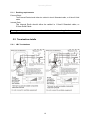
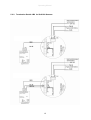
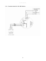
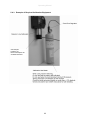
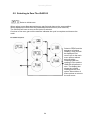
Operating Manual
iGAS100
II2 GD Ex d IIC T6
Ex tD A21 IP 68 T85°C
Operating Manual
2
Operating Manual
This page is intentionally left blank.
Document Number 317829 (See Last Page for Revision Details)
©2006 Extronics Limited. This document is Copyright Extronics limited.
Extronics reserve the right to change this manual and its contents without notice, the latest
version applies.
3
Operating Manual
Contents
1
2
3
4
5
6
7
Introduction.......................................................................................................... 6
Safety Information and Notes .............................................................................. 7
2.1
Storage of this Manual ................................................................................. 7
2.2
List of Notes ................................................................................................. 7
Gas Detector Types............................................................................................. 8
3.1
Pellistor Technology ..................................................................................... 8
3.2
Infra Red Technology ................................................................................... 8
3.3
Toxsin Technology (Fuel Cell)...................................................................... 8
Junction Box types ............................................................................................ 10
4.1
JB1 ............................................................................................................. 10
4.2
JB2 ............................................................................................................. 10
4.3
JB3 ............................................................................................................. 10
4.4
JB4 ............................................................................................................. 10
4.5
JB5 ............................................................................................................. 10
Installation ......................................................................................................... 11
5.1
Customer sealing and earthing responsibilities .......................................... 11
5.1.1
Earthing requirements......................................................................... 12
5.2
Termination details ..................................................................................... 12
5.2.1
JB1 Terminations ................................................................................ 12
5.2.2
Termination Details JB2 for 102 Sensors........................................... 13
5.2.3
Termination details for JB 2 MK3 Pellistors........................................ 14
5.3
Basic Operation of JB 3,4 and 5................................................................. 15
5.3.1
Basic Layout........................................................................................ 15
5.3.2
Powering on the system...................................................................... 15
5.3.3
What to do if the alarm operates ......................................................... 16
5.3.4
Editing and Display Options ................................................................ 17
5.3.5
Entering the USER password.............................................................. 17
5.3.6
Users Menu......................................................................................... 18
5.3.7
Fault Conditions .................................................................................. 19
5.3.8
Over or Under Range Indication.......................................................... 19
5.3.9
Password Protected Menus ................................................................ 20
5.4
Zero and Calibration................................................................................... 21
5.4.1
Equipment for Calibration and Methodology ....................................... 22
5.4.2
Calibration Requirements.................................................................... 22
5.4.3
Example of Required Calibration Equipment ...................................... 23
5.5
Selecting to Zero The iGAS100.................................................................. 24
5.6
Selecting to Calibrate the iGAS100 ............................................................ 25
Intended Purpose Usage................................................................................... 29
6.1
Transportation and Storage........................................................................ 29
6.2
Authorized Persons .................................................................................... 29
6.3
Cleaning and Maintenance......................................................................... 29
6.4
Safety Precautions ..................................................................................... 30
6.5
Cleaning and Maintenance Intervals .......................................................... 30
6.6
Aggressive substances and environments ................................................. 30
6.7
Exposure to external stresses .................................................................... 30
Technical Data .................................................................................................. 31
4
Operating Manual
8 Type Codes ....................................................................................................... 32
9 ATEX Marking ................................................................................................... 33
10
Certification.................................................................................................... 35
11
Manual Revision ............................................................................................ 42
5
Operating Manual
1 Introduction
The iGAS100 series of gas detectors are designed to provide an accurate, cost
effective and reliable gas detection solution. The iGAS100 range incorporates a
number of sensing technologies, each of which can be utilised in a standard field
housing with no field display or alternatively a field housing with a local display which
can be adjusted using magnets for calibration and alarm set point adjustment.
The iGAS100 series of detectors utilise microprocessor technology to give a stable
process signal output, and allow for a 4-20mA or digital addressable output signal.
The digitally addressable sensors are installed on a single cable run, which
dramatically reduces installation costs.
The iGAS100 series of sensors can be combined with the iGAS700 controller for
local display and calibration.
The integrated processor can be used to pre-calibrate the sensor prior to installation.
Alternatively calibration can be achieved on site via the Extronics control panel or
locally using a handheld PC device or laptop.
6
Operating Manual
2 Safety Information and Notes
2.1 Storage of this Manual
Keep this user manual safe and in the vicinity of the device. All persons who have to work on
or with the device should be advised on where the manual is stored.
2.2 List of Notes
The notes supplied in this chapter provide information on the following.
• Danger / Warning.
o Possible hazard to life or health.
• Caution
o Possible damage to property.
• Important
o Possible damage to enclosure, device or associated equipment.
• Information
o
Notes on the optimum use of the device
Important
Ensure that the cable is used which suits the environment in which the
iGAS100 is installed.
Important
The housing must be grounded to a minimum 20A ground.
Important
If the iGAS100 is to be used in a hazardous area ensure the certification
marks on the side of the main housing match the zones certification
requirements. In such cases do not operate the iGAS100 without the
cover correctly screwed in place.
Important
The iGAS100 must be supplied via a suitable fuse or circuit breaker.
Note
Use 1.5mm2 Cable
Note
Do not Exceed 50 metres for Pellistor sensors
Note
Do not Exceed 200 metres for 4-20mA devices.
Note
All cable entries are M20 x 1.5mm
7
Operating Manual
3 Gas Detector Types
3.1 Pellistor Technology
The pellistor or catalytic gas detector is based upon the whetstone bridge circuit. A
current passes through the bridge and heats the circuit to a specific temperature.
One of the resistors imbedded in a glass bead is exposed to the sample or target gas
in the detector housing and located behind a scintered metal flame arrestor.
Upon being exposed to the target gas a change in the surface temperature of the
bead occurs as the target gas is oxidised causing a change in the beads resistance
creating an electrical imbalance in the bridge circuit.
The measured electrical change is proportional to the concentration of target gas. A
gas detector must generally be calibrated with the target gas in air at a known
concentration.
Pellistor technology has a proven historic background stretching back many decades
and is one of the commonest and least costly forms of monitoring flammable gas
leaks.
Pellistors can be calibrated for the measurement of non-organic gases such as
hydrogen and carbon monoxide.
The Pellistor normally expresses the measured value as a percentage of the Lower
Explosive Limit of the gas (%LEL)
3.2 Infra Red Technology
Infra Red technology is based upon emitted energy absorption by the target gas. An
infra red source located behind a scintered metal flame arrestor emits pulsed Infra
Red energy. When the sensor is exposed to the target gas the gas absorbs energy.
The measured difference between the emitted energy and the remaining energy is
proportional to the concentration of the target gas.
This value can be expressed as a percentage of the Lower Explosive Limit of the gas
(%LEL), or alternatively as a percentage by volume of a mixture.
Infra red energy is not absorbed by all gases, for example molecules which are
diatomic of the same element such as, hydrogen (H2), Chlorine (Cl2), Oxygen (O2)
do not absorb Infra Red radiation hence they cannot be measured using this
technology.
3.3 Toxsin Technology (Fuel Cell)
Toxsin Cell Technology is based on a fuel cell which in essence is a battery. A fuel
cell is located behind a semi permeable membrane and when it is exposed to a
target gas a reaction on the surface occurs causing a current to flow in the cell. The
current flow is proportional to the amount of gas present. The concentration is
8
Operating Manual
expressed either as a percentage by volume or alternatively in parts per million
(ppm).
Fuel cell technology is generally used for the measurement of inorganic compounds
such as oxygen, hydrogen sulphide, hydrogen chloride, chlorine, etc.
9
Operating Manual
4 Junction Box types
The iGAS100 series of gas detector solutions can be used with 4 different junction box
configurations, which allow flexibility when deploying gas detection solutions.
4.1 JB1
The JB1 configuration is a basic Exd junction box which has a set of screw terminals
to connect directly to the gas detector. This type junction box can be with Toxic and
Infrared gas detectors.
The output from each of these gas detectors is a regular 4-20mA signal.
DANGER!
The 4-20mA signal is NOT intrinsically safe. Never connect the output of
the sensor to an intrinsically safe source without the use of a safety
barrier.
4.2 JB2
The JB2 configuration is a junction box with an added digitally addressable PCB, this
configuration can only be used in conjunction with the iGAS700 controller.
4.3 JB3
The JB3 configuration is a junction box with an added local display and a 4-20mA output.
This type of junction box can be used as a standalone sensor or as part of a larger system.
The JB 3 solution has the alarm relay option fitted
4.4 JB4
The JB4 configuration is identical as the JB3 configuration without the Alarm Relay outputs.
4.5 JB5
The JB5 configuration is identical to the JB4 with the addition of the digitally addressable
PCB, this configuration can be used in conjunction with the iGAS700 controller.
.
10
Operating Manual
5 Installation
5.1 Customer sealing and earthing responsibilities
The iGAS100 range is designed for use in Zone 1 and Zone 2 hazardous areas and is ATEX
certified. To maintain compliance it is imperative the installer of the equipment observes the
following installation guidelines. Failure to do so could compromise the protection concept of
the equipment. All Cable entries are M20x1.5mm.
11
Operating Manual
5.1.1
Earthing requirements
External Earth
The External Earth should either be cabled in 4mm2 Stranded cable, or 6.0mm2 Solid
cable
Internal Earth
The Internal Earth should either be cabled in 1.5mm3 Stranded cable, or
2.5mm Solid Cable.
Warning
Glands and cables must be suitable for the zone of application
5.2 Termination details
5.2.1
JB1 Terminations
12
Operating Manual
5.2.2
Termination Details JB2 for iGAS100 Sensors
13
Operating Manual
5.2.3
Termination details for JB 2 MK3 Pellistors
14
Operating Manual
5.3 Basic Operation of JB 3,4 and 5
Before attempting to operate the iGAS100 single channel gas detectors ensure that
the installation ad calibration instructions have been followed.
5.3.1
Basic Layout
A calibration label will be fitted to the side of the unit.
This label will indicate when the system is next due for
calibration. Regular calibration (usually 6 months) is
vital for correct operation.
The gas being monitored by the
iGAS100 will be indicated in this
area along with the units of
measure.
The Function button is used to
cancel alarms or access the
internal software function and
system set up.
5.3.2
Powering on the system
After ensuring correct installation of the iGAS100 the unit may be switched on. When
first switched on the iGAS100 will first display T903 then its software version, sensor
type, range, address and then commence a 300 second count down timer. This
allows the sensor to stabilise before operation. During this time the analyser alarm
outputs are off and the 4-20mAoutput is fixed at 4mA. At the end of the count down
the unit will indicate either '903’ or a continuously updating gas concentration
depending which mode of operation has been selected.
15
Operating Manual
5.3.3
What to do if the alarm operates
The iGAS100 JB3 & JB4 are fitted with a number of interfaces which may be
connected to other systems in the location that the gas detector is being used. For
instance the iGAS100 could be set up to cut off the mains gas supply to a boiler in
the event of a gas leak or it could be set up to activate alarms external to the unit in
the event of a toxic gas leak.
Whatever interfaces are connected the following will happen as a minimum.
The highest alarm level
that has been
exceeded will flash on
and off on the LED
display.
The iGAS100 is fitted with a
function button which is
activated using a magnetic
pointer provided with the
system. By following the
instructions in this manual
the menu system can be
accessed to set alarm levels
change ranges or sensor
type.
Use the magnetic ‘pointer’ once to mute the alarm.
(The ‘SIL’, silence function) In this instance note
that the outputs stay in the alarm state as does the
display.
Select ‘RES’ or RESET function to reset the alarm.
Note if the hazard is still present the alarms will be
re-activated.
Note that the system may be configured to act as a simple 4-20mA device in which
case indicated alarm levels will be disabled.
16
Operating Manual
5.3.4
Editing and Display Options
As supplied and installed the iGAS100 will be programmed for the following:
1. The Target Gas. For instance Methane, Propane, Butane, Carbon Monoxide,
Nitric Oxide etc
2. The levels which once exceeded will results alarm outputs AL1 and AL2 being
activated
3. The range over which the sensor is to operate.
It will not normally be necessary for a user to need to change any of these
parameters. To attempt to change any of the parameters without the necessary
specialist knowledge and training could compromise the performance of the gas
detector. The operator does have access to zero the unit and check or change the
alarm levels. This feature is password protected. Passwords are entered as follows:
5.3.5
Entering the USER password
With the display indicating 903
hold the magnetic pointer over
the Fn area..
Bring the magnetic pointer over
the Fn area and the digit will
Increment.
Increment the display to read ‘1’
The display will indicate PASS
remove the pointer when this is
displayed.
The display will now
indicate all zero's. The
first zero will be flashing.
The T903 is expecting a
password
Hold the magnetic pointer
Over the Fn area. Each digit
In turn will flash
When all digits are
flashing remove the
pointer. The display will
now alter to indicate the
USER menu (see next
section)
17
Operating Manual
5.3.6
Users Menu
Select to ZERO and the
sequence of options
Reading, Zero End will
be displayed. End
returns you to the
main menu options
without doing
anything. Selecting
either the reading or
Zero and the iGAS100
will perform a zero.
The display then
shows the ‘Zeroed’
reading and the ‘End’
option. Select either of
these options to return
to the main menu.
The end option returns the iGAS100 to Normal Operation
18
Operating Manual
5.3.7
Fault Conditions
The iGAS100 can detect and report faults which may develop with the sensor.
5.3.8
Over or Under Range Indication.
If the gas being sensed exceeds the range of the sensor fitted to the iGAS100 by
more than 5% of the sensors range then this is indicated by the display indicated
below.
When the gas concentration is back in range the iGAS100 reverts to normal
operation.
This indicates Gas over range
If the iGAS100 is being used as a 4-20mA transmitter
then the output will drop to below 4mA to indicate a
fault condition
In some circumstances for example if the temperature conditions exceed the rating of
the sensor or if the calibration period has been exceeded the sensor may drop below
the range of the iGAS100. Should the sensor signal drop below the zero point by
more than 5% of the sensors range this is indicated by the display shown below.
When the gas concentration is back in range the iGAS100 reverts to normal
operation.
This indicates Gas under range
If the iGAS100 is being used as a 4-20mA transmitter
then the output will drop to below 4mA to indicate a
fault condition
In both cases the fault must be continuously present for more than 5 seconds
19
Operating Manual
5.3.9
Password Protected Menus
The iGAS100 stores its calibration and set up information in non-volatile memory. To
access these functions it is necessary to enter a password as previously described.
These password protected functions should only be carried out by trained staff
otherwise problems can arise due to poor calibration or zeroing. Similarly if detector
set up functions are incorrectly set then poor performance could result.
Follow the procedure described below to gain access to the system calibration and
set up functions.
With the display indicating
hold the magnetic pointer
over he Fn area..
The display will indicate PASS
remove the pointer when this
is displayed.
The display will now indicate
all zero's. The first zero will
be flashing. The iGAS100 is
expecting a password
When all digits are flashing
remove the pointer. The
display will now cycle through
the available options
Bring the magnetic
pointer over the Fn area
and the digit will
increment. Increment
the display to read ‘2’
Hold the magnetic pointer
over the Fn area. Each
digit in turn will flash
20
Operating Manual
5.4 Zero and Calibration
Zero and Calibration.
In common with most measuring devices gas detection equipment requires regular
calibration if it is to operate correctly. Gas detectors are usually calibrated using
either a synthetic air mixture or Nitrogen depending on the detector to obtain a zero
point and a known gas concentration to obtain a calibration point. Usually bottled
calibration gas is used to calibrate the detectors. In some cases this is either not
practical or simply not desirable due to the nature of the gas. In such cases
electrochemical gas generators can be used or ampules of solution mixed on the
spot in a known volume. In some cases, Chlorine detectors being a good example an
amount of atmospheric moisture (Rh) is required for the detector to function correctly.
In such cases bottled gas is of no use and a gas generator must be employed.
The frequency of calibration is governed mainly by two factors, the type of detector
and the environment it is located in. Calibration records should be kept for gas
detection equipment and should indicate in particular the state of calibration of the
detector both before and after calibration. Examination of such records over time can
then be used to determine if a detector in a given environment is capable of
maintaining calibration for the chosen period. If not then consideration should be
given to either reducing the interval between calibrations or choosing an alternative
detection technology.
21
Operating Manual
5.4.1
Equipment for Calibration and Methodology
A gas detector calibration kit will normally include:•
•
•
•
•
•
Zero Gas Bottle or Air Pump/Scrubber
Calibration Gas or Gas Generator
Calibration Gas Adaptor (possible this is a permanent fitment in hard to reach
locations)
Gas flow Regulators
Introduction Tubing (again possibly permanent fitment in hard to reach
locations)
Calibration Stickers (to indicate date of calibration, next due date and
certificate number)
In principle the sequence of events are as follows:1. Inhibit the control panel during calibration so the act of introducing gas
does not set off the alarm. This will vary from system to system.
2. Fit the calibration gas adaptor to the sensor if this is not a permanent
fitment.
3. Flow zero gas for the recommended period for the detector and note
the reading. Note that many gas detectors will zero clamp the reading.
4. Flow Calibration gas for the recommended period for the detector and
note the reading.
5. Re-introduce zero gas for the recommended period for the detector and
follow the manufacturers procedure to zero the detector
6. Re-introduce calibration gas for the recommended period for the
detector and follow the manufacturers’ instructions to calibrate the
detector.
7. Observe and record the detector reading whilst flowing calibration gas.
8. Update the calibration status stickers on the detector.
5.4.2
Calibration Requirements
Zero and Calibration Gas should be applied accordingly.
1). Pressure 800 to 1100mB with standard calibration
2). Flow rate 1 – 1.5 litres / min (With process off)
Calibration Gas to be used should be advised based upon application
Please contact Extronics for further assistance.
22
Operating Manual
5.4.3
Example of Required Calibration Equipment
Gas Adaptor
P/N4011101
Note This adaptor fits
all iGAS Detectors
23
Operating Manual
5.5 Selecting to Zero The iGAS100
Select to initiate zero
When opting to zero flow appropriate zero gas first and observe the zero condition.
When stable select ZERO from the password protected menus (enter 200 first).
The iGAS100 will zero as soon as the option is selected.
Continue to flow zero gas until the detector indicates the cycle is complete and observe the
result
Select to ZERO and the
sequence of options
Reading, Zero, End will
be displayed. End
returns you to the main
menu options without
doing anything.
Selecting either the
reading or Zero and the
iGAS100 will perform a
zero. The display then
shows the ‘zeroed’
reading and the ‘End’
option. Select either of
these options to return to
the main menu.
24
Operating Manual
5.6 Selecting to Calibrate the iGAS100
The iGAS100 has now
calibrated the detector. The
display now alternates between
a display of the current gas
value and the word END. The
quality of the calibration can be
observed. When satisfied select
the Fn button to return to the
main menu
25
Operating Manual
Select to calibrate 4-20mA loop O/P
The ‘C420’ function is used to calibrate the 4-20mA loop output by the following
method.
Select to zero 4-20mA loop O/P
Follow the same basic procedure described for calibration but this time use it to zero
the 4-20mA loop output.
26
Operating Manual
Select to force 4-20mA loop O/P
The ‘420’ function allows the user to output a set current for diagnostic purposes on
the 4-20mA loop output. The output once set will remain for a short period until the
system times out and returns to normal operation or a new value is input. Maximum
output value is 35mA.
Select to calibrate the pellistor drive current
This function can be used to eliminate any read errors between the set drive current
for a pellistor head and the current measured using an external ammeter. For
example if the iGAS100 indicates it is outputting 360mA to the measuring head but
an external ammeter indicates 350mA then select C360 and increment the displayed
value until 360mA is indicated on the ammeter.
27
Operating Manual
Select to set up initial system zero
The ‘POT 1’ function sets up an initial zero setting using an electronic ‘potentiometer’.
Once set at the factory this should not need to be re-set during the operational life of
the iGAS100.
Select to set up initial system Gain
The ‘POT 2’ function sets up an initial gain setting using an electronic ‘potentiometer’.
Once set at the factory this should not need to be re-set during the operational life of
the iGAS100
Select to test relay output function
This option will energise all the output relays for a short period. Note this feature is
only operational on models fitted with relay outputs.
Select to return the iGAS100 to normal operational mode.
28
Operating Manual
6 Intended Purpose Usage
Important
Before setting the units to work, read the technical documentation
carefully.
Important
The latest version of the technical documentation or the corresponding
technical supplements is valid in each case.
The iGAS100 is built using modern components and is extremely reliable in
operation; however it must only be used for its intended purpose. Please note that
the intended purpose also includes compliance with the instructions issued by the
manufacturer for installation, setting up and service.
Any other use is regarded as conflicting with the intended purpose. The manufacturer
is not liable for any subsequent damage resulting from such inadmissible use. The
user bears the sole risk in such cases.
6.1 Transportation and Storage
All iGAS100 devices must be so transported and stored that they are not subjected to
any excessive mechanical stresses.
6.2 Authorized Persons
Only persons trained for the purpose are authorized to handle the iGAS100; they
must be familiar with the unit and must be aware of the regulation and provisions
required for explosion protection as well as the relevant accident prevention
regulations.
6.3 Cleaning and Maintenance
The iGAS100 and all its components require no maintenance and are selfmonitoring. All work on the iGAS100 by personnel who are not expressly qualified for
such activities will cause the Ex approval and the guarantee to become void.
29
Operating Manual
6.4 Safety Precautions
Important
For the installation, maintenance and cleaning of the units, it is
absolutely necessary to observe the applicable regulations and
provisions concerned with explosion protection (EN 50014, EN 6007914:2003) as well as the Accident Prevention Regulations.
6.5 Cleaning and Maintenance Intervals
The cleaning intervals depend on the environment where the system is installed.
6.6 Aggressive substances and environments
The iGAS100 is not designed to come into contact with aggressive substances or
environments, please be aware that additional protection may be required.
6.7 Exposure to external stresses
The iGAS100 is not designed to be subjected to excessive stresses e.g. vibration,
heat, impact. Additional protection is required to protect against these external
stresses.
The iGAS100 will require additional protection if it is installed in a location where it
may be subjected to damage.
30
Operating Manual
7 Technical Data
•
•
•
•
•
Toxic Loop Powered
Pellistor 4-20mA 150mA
Infrared 90mA
903 250mA 24VDC
Certification Number
EPSILON 07 ATEX 2286X
II 2G Ex d IIC T6
Certification Type
II 2GD Ex d IIC T6 Ex tD A21 IP68 T85°C
Dimensions
145 x 208 x mm
IP Rating
IP68
Ambient Temperature
-20°C to 50°C
Weight
Typically 1.5 kg
Operating Humidity
Range
5-60% RH Electo Chem
0-95%RH Non Condensing
Operating Voltage
24VDC or Loop Powered
Repeatability
Sensor Dependant
Zero Drift
Sensor Dependant
Response Time
Sensor Dependant
Cable Entries
2 x M20x1.5mm
Enclosure Material
Epoxy Coated Aluminium Alloy.
Sensor Material
316 Stainless Steel
31
Operating Manual
8 Type Codes
iGAS100 Hazardous Area Gas Sensors
iGAS100-[#1]-[#2]-[#3]
Specify Option [#1] - Sensor Type
Toxic
Infrared
Pellistor
T
R
P
Specify Option [#2] Junction Box Type
Exd Junction Box with 4-20mA Output Only
(Not Suitable for Standalone Pellistor)
Exd Junction Box with Digitally Addressable
Exd Junction Box With Display, 4-20mA Output and Local Alarm Relays
Exd Junction Box With Local Display and 4-20mA Output
Exd Junction Box With Digitally Addressable and Local Display
JB1
JB2
JB3
JB4
JB5
Specify Option [#3] Gas Detector type
Nitrogen dioxide
Sulphur dioxide
Hydrogen sulphide
Chlorine
Oxygen
Nitric oxide
Ammonia
Ammonia High Level
Carbon monoxide
Flammability
Carbon dioxide
Freon
Hydrogen cyanide
NO2
SO2
H2S
CL2
O2
NO
NH3
NH3HIGH
CO
FL
CO2
FREON
HCN
Gas types and Sensing Technologies
Type
N02 S02 H2S CL2
O2
NO NH3 NH3
High
CO
FL
CO2
FREON HCN
Toxin
Infrared
Pellistor
FL
100%
ppm Min
10
5
20
5
5%
10
100
250
100
5000
5
ppm
Max
50
50
250
50
5%
5000
200
35% 250 500
32
5000 1000
Operating Manual
9 ATEX Marking
33
Operating Manual
34
Operating Manual
10 Certification
35
Operating Manual
36
Operating Manual
37
Operating Manual
38
Operating Manual
39
Operating Manual
40
Operating Manual
41
Operating Manual
11 Manual Revision
Revision
01
02
03
Description
Initial Release
Revised to Include JB5
Images for iGAS modified, Calibration info
added to with flow rate.
42
Date
16/01/08
07/04/08
02/06/08
By
NS/PL
NS
NM