1
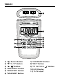
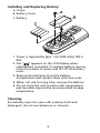
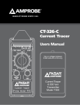
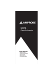
TMD-51 Thermocouple Thermometer K/J Type with Memory Users Manual • Mode d’emploi • Bedienungshandbuch • Manual d’Uso • Manual de uso Thermocouple Thermometer K/J Type with Memory Users Manual June 2010, Rev.1 ©2010 Amprobe Test Tools. All rights reserved. Printed in Taiwan English TMD-51 Limited Warranty and Limitation of Liability Your Amprobe product will be free from defects in material and workmanship for 1 year from the date of purchase. This warranty does not cover fuses, disposable batteries or damage from accident, neglect, misuse, alteration, contamination, or abnormal conditions of operation or handling. Resellers are not authorized to extend any other warranty on Amprobe’s behalf. To obtain service during the warranty period, return the product with proof of purchase to an authorized Amprobe Test Tools Service Center or to an Amprobe dealer or distributor. See Repair Section for details. THIS WARRANTY IS YOUR ONLY REMEDY. ALL OTHER WARRANTIES WHETHER EXPRESS, IMPLIED OR STAUTORY - INCLUDING IMPLIED WARRANTIES OF FITNESS FOR A PARTICULAR PURPOSE OR MERCHANTABILITY, ARE HEREBY DISCLAIMED. MANUFACTURER SHALL NOT BE LIABLE FOR ANY SPECIAL, INDIRECT, INCIDENTAL OR CONSEQUENTIAL DAMAGES OR LOSSES, ARISING FROM ANY CAUSE OR THEORY. Since some states or countries do not allow the exclusion or limitation of an implied warranty or of incidental or consequential damages, this limitation of liability may not apply to you. Repair All test tools returned for warranty or non-warranty repair or for calibration should be accompanied by the following: your name, company’s name, address, telephone number, and proof of purchase. Additionally, please include a brief description of the problem or the service requested and include the test leads with the meter. Non-warranty repair or replacement charges should be remitted in the form of a check, a money order, credit card with expiration date, or a purchase order made payable to Amprobe® Test Tools. In-Warranty Repairs and Replacement – All Countries Please read the warranty statement and check your battery before requesting repair. During the warranty period any defective test tool can be returned to your Amprobe® Test Tools distributor for an exchange for the same or like product. Please check the “Where to Buy” section on www.amprobe.com for a list of distributors near you. Additionally, in the United States and Canada In-Warranty repair and replacement units can also be sent to a Amprobe® Test Tools Service Center (see address below). Non-Warranty Repairs and Replacement – US and Canada Non-warranty repairs in the United States and Canada should be sent to a Amprobe® Test Tools Service Center. Call Amprobe® Test Tools or inquire at your point of purchase for current repair and replacement rates. In USA Amprobe Test Tools Everett, WA 98203 Tel: 877-AMPROBE (267-7623) In Canada Amprobe Test Tools Mississauga, ON L4Z 1X9 Tel: 905-890-7600 Non-Warranty Repairs and Replacement – Europe European non-warranty units can be replaced by your Amprobe® Test Tools distributor for a nominalv charge. Please check the “Where to Buy” section on www.amprobe.com for a list of distributors near you. European Correspondence Address* Amprobe® Test Tools Europe In den Engematten 14 79286 Glottertal, Germany Tel.: +49 (0) 7684 8009 - 0 *(Correspondence only – no repair or replacement available from this address. European customers please contact your distributor.) TMD-51 11 10 1 4 7 1) “ ” Power Button 2) “q/°C /°F” Button 3) “p/ ” Button 4) “ADJ/HOLD” Button 5) “APO/TYPE” Button 6) “MAX/MIN” Button 2 3 5 6 8 9 7) “CLR/READ” Button 8) “REC” Button 9) “T1 T2/T1-T2/ 10) LCD Display 11) T1/T2 Input ” Button Screen Display 3 4 5 6 7 2 8 9 1 1) Temperature display 2) Type of T/C thermocouple “K” or “J” 6) Review the data you recorded 7) Record the data 3) Auto power off 8) Degrees °C /°F 4) MAX/MIN/MAX-MIN reading 9) T1/T2 thermocouple or T1-T2 differential 5) Measurement reading stop CONTENTS SYMBOLS............................................................................. 2 UNPACKING AND INSPECTION........................................... 2 INTRODUCTION................................................................... 3 Features........................................................................... 3 OPERATION INSTRUCTIONS................................................ 3 “ “ Power Button.......................................................... 3 “ / °C / °F” Button........................................................ 3 “ / ” Button............................................................. 4 “ADJ/HOLD” Button....................................................... 4 “APO/TYPE” Button........................................................ 4 “MAX/MIN” Button........................................................ 4 “CLR/READ” Button........................................................ 5 “REC” Button.................................................................. 5 “T1 T2 / T1-T2 / ” Button............................................ 5 ADJUST THERMOCOUPLE OFFSET...................................... 6 SPECIFICATION..................................................................... 6 MAINTENANCE.................................................................... 8 1 SYMBOLS � Caution! Refer to the explanation in this Manual � Conforms to relevant Australian standards � Complies with European Directives Tested Comply With FCC Standards = Do not dispose of this clamp meter as unsorted municipal waste. �WARNING and PRECAUTIONS • To avoid electrical shock, do not use this instrument when working voltages at the measurement surface over 24V AC or DC. • To avoid damage or burns, do not make temperature measurement in microwave ovens. • Repeated sharp flexing can break the thermocouple leads. To prolong lead life, avoid sharp bends in the leads, especially near the connector. Unpacking and Inspection Your shipping carton should include: 1 TMD-51 Meter 1 Manual 2 K type Thermocouple 4 AAA Batteries 1 Plain white box If any of the items are damaged or missing, return the complete package to the place of purchase for an exchange. 2 INTRODUCTION This instrument is a portable 3½ digit, compact-sized digital thermometer designed to use external K-type and J-type thermocouple as temperature sensor. It also has the feature that sensor offset can be adjusted for in the field. There are 2 sets of sockets for thermocouple plugs at the top of instrument marked with T1 and T2. Features • Data Storage for 125 samples. • Highly accurate dual input thermometer with 0.1% basic accuracy. • Robust protective Holster. • Thermocouple offset adjust. • °C/°F selection. • MIN/MAX/HOLD functions. • Display back-light. • Auto-Power Off. • Auto-Range selection 0.1/1°. • Wide measuring ranges suit for versatile applications. OPERATING INSTRUCTIONS “ ” Power Button Press the “ ” key turns the thermometer. “/°C/°F” Button Reading are displayed in either degrees Celsius(°C) or degrees Fahrenheit(°F). When the thermometer is turned on, it is set to the temperature scale that was in use when the thermometer was last turned off. To change the temperature scale, press the “°C/°F” key. 3 “ / ” Button Press the “ ” key to trigger on the Back-Light. Press the “ ” key again to make the Back-Light lighter and press “ ” key once more to cancel the Back- Light function. Back-Light on g lighter g Back-Light off. “ADJ/HOLD” Button Press the “HOLD” key to enter the Data Hold mode, the “HOLD” annunciator is displayed at the higher-center of display. When HOLD mode is selected, the thermometer held the present readings and stops all further measurements. Press the “HOLD” key again cancels HOLD mode, causing thermometer to resume taking measurements. “APO/TYPE” Button Press “TYPE” key to select the type of T/C, thermocouple “K” or “J”. Make sure the proper type has been selected. Pressing and holding down “APO” key for 2 seconds to trigger on or off APO(Automatic Power Off) mode, and then APO annunciator will appear or disappear on the display. Power is automatically turned off, if no operation for a period of time, and “APO” annunciator is displayed at upper-left corner when APO function is enabled. “MAX/MIN” Button Press “MAX/MIN” key to enter the MAX MIN recording mode. (Displays the Maximum reading, Minimum reading, “MAX-MIN” reading stored in recording mode). Press “MAX/MIN” key to cycle through the MAX, MIN, MAX-MIN readings. In this mode, press “HOLD” key to stop recording, all values are frozen, press again to restart recording. In this mode, the APO function and other keys is disabled, excluding “HOLD” and “ ” keys. To prevent accidental loss of MAX, MIN and MAX-MIN, in this mode can only be cancelled by pressing and 4 holding down the “MAX/MIN” key for 2 seconds to exit and erased recorded reading. “CLR/READ” Button Press “READ” key to enter READ Mode, the “READ” annunciator is displayed at upper-right corner. Press “” or “” key to review the data you recorded. The LCD automatically scrolls data and index. Pressing “CLR” key and holding down for 2 seconds to clear the memory data. “REC” Button There are 125 data could be recorded into memory. Press “REC” key to record the data, press once to record another one till the memory is full. When the data is recorded, “REC” mark is displayed at the Upper-Right corner. If the memory is full, data will not be recorded into the memory and “REC” mark will not be displayed. Data can be recorded after it is cleared. “T1 T2/T1-T2/ ” Button Press “T1”, “T2”, “T1-T2” key to select input mode T1, T2 or T1-T2. The input selection indicates which input is selected for display. T1 thermocouple, T2 thermocouple or the differential between the two thermocouples(T1-T2), when the thermocouple is turned on, it is set to T1. 5 ADJUST THERMOCOUPLE OFFSET 1. Insert the thermocouple into a known temperature (T) until the display equal to known temperature (T). ex: ice point at 0°C / boiling water at 100°C 2. Press “” or “” to add or subtract the value. 3. It can be adjusted ±6°F(±3°C) of default. If you can’t adjust your T/C, please check your T/C or send the meter to be calibrated. 4. Press “ ” key to confirm. SPECIFICATION Electrical Temperature Scale Celsius or Fahrenheit user-selectable Measurement Range K-Type -100°C to 1372°C, (-150°F to 1999°F) J-Type -100°C to 1200°C, (-150°F to 1999°F) Accuracy Accuracy is specified for operating temperatures over the range of 18°C to 28°C (64°F to 82°F), for 1 year, not including thermocouple error. ± (0.1%rdg+1°C) on °C ± (0.1%rdg+2°F) on °F Temperature Coefficient 0.1 times the applicable accuracy specification per °C from 0°C to 18°C and 28°C to 50°C (32°F to 64°F and 82°F to 122°F). 6 Input Protection 24V dc or 24V ac rms maximum input Voltage on any combination of input pins. Input Connector Accepts standard miniature thermocouple Connectors (flat blades spaced 7.9mm, center to center). Environmental Ambient Operating Ranges 0°C to 50°C (32°F to 122°F) <80% R.H. Storage Temperature -20°C to 60°C (-4°F to 140°F) <70% R.H. General Display 3½ digit liquid crystal display (LCD) with maximum reading of 1999. Overrange “OL” or “-OL” is displayed. Auto Power Off Approximately 20 minutes Battery 4 X 1.5V AAA Reading Rate 1 time per second Dimensions 160 mm (H) x 83 mm (W) x 38 mm (D); 6.3 in (H) x 3.3 in (W) x 1.5 in (D). Weight Approx. 240g (0.5lb) including batteries 7 Supplied Wire 4 feet type “K” thermocouple bead wire (Teflon tape insulated). Maximum insulation temperature 200 °C (392°F). Wire accuracy ±2.2°C or ±0.75% of reading (whichever is greater) from 0°C to 800°C. � - EMC: Conforms to EN61326-1. This product complies with requirements of the following European Community Directives: 89/ 336/ EEC (Electromagnetic Compatibility) and 73/ 23/ EEC (Low Voltage) as amended by 93/ 68/ EEC (CE Marking). However, electrical noise or intense electromagnetic fields in the vicinity of the equipment may disturb the measurement circuit. Measuring instruments will also respond to unwanted signals that may be present within the measurement circuit. Users should exercise care and take appropriate precautions to avoid misleading results when making measurements in the presence of electronic interference. MAINTENANCE AND REPAIR �WARNING To avoid possible electrical shock, disconnect the thermocouple connectors from the thermometer before removing the cover. 8 Installing and Replacing Battery A. Screw B. Battery Cover C. Battery 1. Power is supplied by 4pcs 1.5V (SIZE AAA) UM-4 R03. ” appears on the LCD display when 2. The “ replacement is needed. To replace battery remove screw from back of meter and lift off the battery cover. 3. Remove the batteries from the battery compartment and replace them with new ones. 4. When not use for long time, remove the battery. 5. Do not store the unit in place with temperature and humidity beyond the recommended storage temperature. Cleaning Periodically wipe the case with a damp cloth and detergent, do not use abrasives or solvents. 9