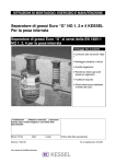
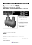
1
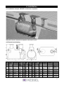
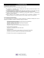
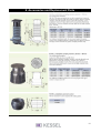
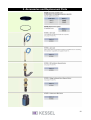
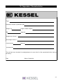
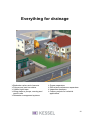
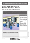
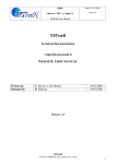
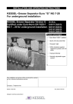
INSTALLATION AND OPERATING INSTRUCTIONS
KESSEL – Oil / Fuel separator
KESSEL – Coalescence separator
PE Separators according to Euro-norm EN 858 NG 3-20
KESSEL – Oil / Fuel separator
KESSEL – Coalescence separator
Accordino to EN 858
NG 3-20 for underground installation
99403-99420
(.10/.15/.30/.40) (B/D)
99503-99515
(.10/.15/.30/.40) (B/D)
Product advantages
Easy on-site mobility without the
need for heavy machinery
Simple and quick installation and
hook up
Recycable material
Seamless body due to monolith
construction – 100% watertight
The installation and service of this unit should be carried
out by a licensed professional servicer
Company - Telephone No.
Edition 07/02-HG
(Subject to technical amendment
ID number 010-615
Table of Contents
1. Safety Precautions and Helpful Hints
page 3
2. General
2.1 Application
page 4
2.2 Separator description
page 4
3. Transport and Storage
3.1 Transportation
page 5
3.2 Temporary Storage
page 5
4. Installation
4.1 Oil / Fuel separator
page 6
4.2 Dimensioned Drawing
page 6
4.3 Coalescence Separator
page 7
4.4 Dimensioned Drawing
page 7
4.5 Installation Area
page 8
5. Commissioning
5.1 Separator Commissioning
page 9
5.2 Commissioning Participants
page 9
6. Separator Contents Disposal
page10
7. Maintenance
page10
8. Accessories and Replacement parts
page 11
9. Guarantee
page 13
10.
page 16
Important Contacts / Info
2
1. Safety Precautions
Dear Customer,
Before the KESSEL Oil / Fuel or Coalescence separator is installed and placed in operation
please carefully read and follow all of the instructions contained in this Installation,
Maintenance and User's Manual.
Upon delivery of the KESSEL separator please thoroughly inspect the separator to make
sure that it has not been damaged during shipping. In case damage has occurred to the
separator, please follow the instructions listed in the ,Guarantee' section of this user's
manual.
By installation, use, maintenance and repair of this unit please follow all appropriate DIN / VDE /
DVGW safety precautions and accident prevention guidelines. Also please follow any local safety
precautions and accident prevention guidelines established in your area. Also please observe the
following:
•
BGV C22 (formerly VBG 37)
•
DIN 4124 - Safety precautions for excavations / trenches
•
DIN EN 1610 - Standard procedures for the installation of drainage piping
BGR 117 (formerly ZH1/77) - Standard procedures for working in confined spaces
Do not allow any type of wastewater into the separator which could hinder the proper separation
between oils / fuels and water.
ACCESS:
NO SMOKING! Smoking is strictly prohibited near or around the separator at all times !
All sources of ignition or sparks are prohibited near or around the separator at all times !
SLIPPERY WHEN WET! Take caution when standing / walking near the separator. During
disposal, cleaning and maintenance the surrounding area can become extremely slippery due to
spilled oil / fuel.
SEPARATOR AREA REGULATIONS:
No access of the separator for unauthorized personnel
The location of the separator should be chosen carefully as to allow sufficient access for
maintenance, inspection, repair and disposal of the separator.
The wastewater in the separator can contain skin irritants. After coming in contact with
wastewater or the separator itself, it is important to wash, clean and disinfect all skin and
clothing which has been contaminated.
All personnel having anything to do with the separator should have a sound knowledge of the
above safety precautions.
Helpful Hints:
1. Manhole covers on top of fuel separators must not be screwed or locked on.
2. Manhole covers on top of fuel separators must not have ventilation ports.
3. All drains connected to the separator must not have any type of odour trap.
4. All drains connected to the separator should be equipped with sludge traps.
5. Wastewater must not be pumped into the separator, it must be gravity fed.
6.Detergents and cleaners used to clean the separator must not be emulsifiable, they should be
cleaners which separate quickly with water (contact detergent / cleaner manufacturer for
additional details).
3
2. General
2.1 Application
The KESSEL oil / fuel and coalescence separators are of special design to aid in the prevention of
oil / fuel ladened wastewater runoff from entering sewage treatment plants, lakes, rivers and public
drinking water supplies. Handling of the oil / fuel wastewater at the source is the most efficient and
most economical method of handling this polluted wastewater. Installation of a KESSEL oil / fuel or
coalescence separator guarantees the proper treatment of the wastewater according to German
and European regulations.
2.2 Separator description
The KESSEL oil / fuel and coalescence separators are designed for underground installation and
include a separation chamber as well as an integrated sludge / sedimentation separation area. The
body of the separator is manufactured from virgin Polyethylene whose wax-like smooth finish
requires that no other additional coatings are necessary. The upper sections of the separators are
manufactured from Duroplast or Polypropylene. The separators are designed for underground
installation at various pre-specified depths and are available with Class B (12.5 ton) or Class D
(40.0 ton) load manhole covers. Additional technical information concerning the separators can be
found on the nameplate attached to all units as well as the technical specification sheet included in
this manual.
4
3. Transport and Storage
3.1 Transport
Transportation of the KESSEL separator should be
handled only by a transporter who has the proper
knowledge, equipment and employees to handle such
a product. During transport the separator must be
firmly fixed into position and must not be allowed to
move or shift in place. It also must be protected from
other objects coming in contact with the separator
during transport.
If and when the separator is lifted it is important to
follow the following correct procedures: The separator
is not to be lifted with the use of steel cables or chains.
Proper equipment are heavy duty cloth or hemp straps
designed to handle the corresponding loads. The
separator should be lifted by placing the proper straps
beneath the inlet and outlet of the separator as seen in
the illustration. Do not lift the separator by the small
holes between the two manholes covers as illustrated
on this page. In instances where a forklift is used,
secure the separator to the forklift with appropriate
cloth / hemp securing straps.
3.2 Storage
In cases where the separator needs to be temporarily
stored before installation, it is important that the
separator is placed on firm level ground and in an area
where it is protected from coming in contact with other
objects. Storing the separator outdoors will not cause
any problems.
5
4. Installation
4.1 Installation example: KESSEL Oil / Fuel Separator
Illustration shows oil / fuel separator with class D cover
4. 2 Dimensioned drawing
NG
Sludge
trap
actual
Max. sludge
trap height
Sludge DN
trap
equivalent
3
1000 l
650 mm
2000 l
3-6
3000 l
1100 mm
6000 l
3-10
1500 l
650 mm
3000 l
6-15
3000 l
1100 mm
3000 l
10-20
4000 l
1100 mm
8000 l
L/B
in mm
2080 /
150 1200
2300 /
150 1760
2860 /
150 1200
2300 /
200 1760
3060 /
200 1760
T in
mm
min./
max.
950
1280
1000
1330
950
1280
1000
1330
1000
1330
h2 /
h1
1100
1070
1630
1560
1100
1070
1630
1600
1630
1600
Separator
Oil
collection
Max. oil
layer in
mm
900 l
300 l
130
1350 l
450 l
170
1170 l
300 l
130
1350 l
450 l
170
1900 l
600 l
170
Total weight Art. N°
/ volume
331 kg
1800 l
401 kg
4800 l
403 kg
2500 l
401 kg
4800 l
473 kg
5700 l
Class A/B /
Class D
99403.10B
99403.10D
99406.38 B
99406.30D
99410.15B
99410.15 D
99415.30B
99415.30D
99420.40B
99420.40D
6
4. Installation
4.3 Installation example: KESSEL Coalescence separator
Illustration shows coalescence separator with class B cover
4.4 Dimensioned drawing
NG
Sludge
trap
actual
Max. sludge
trap height
Sludge DN
trap
equivalent
3
1000 l
650 mm
2000 l
3-6
3000 l
1100 mm
6000 l
3-10
1500 l
650 mm
3000 l
3-10
3000 l
1100 mm
3000 l
3-15
4000 l
1100 mm
8000 l
L/B
in mm
2080 /
150 1200
2300 /
150 1760
2860 /
150 1200
2300 /
200 1760
3060 /
200 1760
T in
mm
min./
max.
950
1280
1000
1330
950
1280
1000
1330
1000
1330
h2 /
h1
1100
1030
1630
1560
1100
1030
1630
1560
1630
1560
Separator
Oil
collection
Max. oil
layer in
mm
900 l
300 l
130
1350 l
450 l
170
1170 l
300 l
130
1350 l
450 l
170
1900 l
600 l
170
Total weight Art. N°
/ volume
331 kg
1800 l
401 kg
4800 l
403 kg
2500 l
401 kg
4800 l
473 kg
5700 l
Class A/B /
Class D
99503.10B
99503.10D
99506.30 B
99506.30D
99510.15B
99510.15 D
99510.30B
99510.30D
99515.40B
99515.40D
7
4. Installation
4.5 Installation area
When the shipment arrives, please inspect it immediately for damage which may have been
caused during transport / shipping!
The inlet of the KESSEL separator must be installed below the frost level. This can be achieved by
the use of the vertically adjustable upper sections. The manhole covers for the upper sections are
available in load classes B (12.5 ton) and D (40.0 ton) and meet EN 124 standards.
Note - before installation, make sure that no dirt / grit / debris exits between any of the sealing
areas (gaskets). Also check the entire separator to make sure that no cracks, holes or dents have
occurred during transportation or storage.
Before installation, be sure to determine the maximum groundwater level at the site of installation
to make sure that groundwater will never rise higher than the bottom of the outlet.
1. The excavation in which the separator is to be installed must be level and capable of handling
the appropriate loads. The base of the excavation should be comprised of a 25 cm layer of frost
free gravel covered by a 3 to 10 cm layer of sand or fine gravel.
2. Before installation, remove the float switch chamber (coalescence & float switch chamber if a
coalescence separator is being installed) and store in a safe place. Place the separator in the
prepared excavation hole. Make sure the separator is level and rests at the appropriate elevation.
Fill the separator with fresh cold water to the outlet level.
3. The excavation should now be backfilled with non-binding material such as sand, or fine gravel.
Backfill only the main body of the separator, do not backfill around the upper sections. The backfill
should be firmly compacted at incremental levels (approx 30 cm). For load class D (40.0 ton)
situations, the upper section and manhole cover of the underground separator must be
poured into a steel reinforced concrete apron for proper load support. Additional
information regarding this load class D support is available from KESSEL!!
4. Connect the inlet and outlet of the separator to the drainage piping.
5. Install and adjust the upper section(s) of the separator to the desired level and secure with the
included clamp ring (clamp ring will rest on the chamber itself). Final upper section level
adjustments can be made by using the elevation adjustment screws located on the clamp ring.
Back fill the remaining area around the upper sections with sand or fine gravel (leave space for a
15 cm concrete load supporting apron (steel reinforced) if installed Load Class D – 40.0 ton
covers)
NOTICE - Take care not to place any loads on top of the manhole covers and upper sections of the
separator until the separator is completely backfilled and (if required) the load supporting concrete
apron around the manhole covers has completely cured.
8
5. Commissioning
5.1 Separator commissioning
Before the separator is put into service please make sure that:
• The separator is completely clean, including inlet and outlet, and that the interior of the
chamber is free of dirt and debris.
• The cleaned separator is completely filled with clean cold water up to the outlet (this step
should already have taken place in the 'Installation' phase of this user's manual).
• Re-insert the float switch chamber (coalescence & float switch chamber if a coalescence
separator is being installed).
• Replace manhole covers (manhole covers MUST NOT be screwed or fastened to the
separator. Manhole cover should simply rest on the upper sections of the separator).
5.2 Commissioning participants
The commissioning of the separator is usually handled by a tradesman although this can be
handled by a KESSEL contractor or KESSEL employee if desired.
1) The following people should be on hand during the commissioning:
• Building contractor representative
• Plumber / tradesman who will be maintaining the separator
• Building maintenance personnel
• Disposal company who will be handling the disposal account
2) Commissioning preparation
• Separator is completely filled with clean water
3) Commissioning
• Separator to be checked for water tightness and for proper functionality
• Contents of this user's manuals to be discussed with those present
4) Transfer of this manual to the appropriate personnel
9
6. Separator Contents Disposal
The separator should be emptied (disposal) when the oil / fuel storage capacity has reached
approximately 4/5's (80%) of its capacity or every 6 months, whichever is sooner.
In order for a separator to function as designed, it is very important that the separator is emptied at
regular intervals as described above. It is recommended that a licensed disposal company is
contracted to handle the entire disposal procedure.
Disposal procedure
• Remove manhole covers.
• Remove the float switch chamber (coalescence & float switch chamber if disposing a
coalescence separator). Rinse / clean the filter with fresh water and inspect for damage.
• Place disposal truck's suction hose inside separator and remove entire contents of the
chamber (sludge and fuel / oil).
• Rinse and clean interior walls of chamber. Remove any solids or particulates.
• Remove remaining contents inside separator.
• Re-insert the float switch chamber (coalescence & float switch chamber if disposing a
coalescence separator).
• Refill entire separator with cold clean water.
• Clean and grease all accessible seals. Replace seals if necessary.
• Replace manhole covers.
7. Maintenance
Before the separator is placed into service and at regular intervals thereafter (minimum two times
per year), it is important that:
1. The interior and exterior walls of the separator are thoroughly cleaned and checked for
damage. Inlet and outlet equipment should also be checked.
2. All inspection and maintenance work should be logged into this user's manual. Information
concerning each disposal should also be kept on record.
Please take care that:
• This Installation, Service and Maintenance Guide is kept in a safe location where it is always
available.
• The disposal of the separator is only carried out by a certified company.
• Safety precautions listed in this manual and all other relevant safety precautions are followed
at all times.
10
8. Accessories and Replacement Parts
11
8. Accessories and Replacement Parts
12
9. Guarantee
1. In the case that a KESSEL product is defective, KESSEL has the option of repairing or replacing
the product. If the product remains defective after the second attempt to repair or replace the
product or it is economically unfeasible to repair or replace the product, the customer the has the
right to cancel the order / contract or reduce payment accordingly. KESSEL must be notified
immediately in writing of defects in a product. In the case that the defect is not visible or difficult to
detect, KESSEL must be notified immediately in writing of the defect as soon as it is discovered. If
the product is repaired or replaced, the newly repaired or replaced product shall receive a new
warranty identical to that which the original (defective) product was granted. The term defective
product refers only to the product or part needing repair or replacement and not necessarily to the
entire product or unit. KESSEL products are warranted for a period of 24 months. This warranty
period begins on the day the product is shipped from KESSEL to its customer. The warranty only
applies to newly manufactured products. Additional information can be found in section 377 and
378 of the HGB.
2. Wear and tear on a product will not be considered a defect. Problems with products resulting
from improper installation, handling or maintenance will also not be considered a defect.
01.01.2002
13
10. Separator Characteristics
Type
Production number / production year
Weight / kg
length x width X height
EN
Approval
Sludge trap volume / l
Oil storage volume / l
Control stamp
Material
(Accessories)
This unit has been checked for watertightness to be sure that it is fully operational before leaving
the factory.
Date
Name of examiner
14
Important Contacts / Info
Separator Type
Day / Hour
Project description /
Building services supervisor
Address
Telephone / Fax
Builder
Address
Telephone / Fax
Planner
Address
Telephone / Fax
Contracted plumbing company
Address
Telephone / Fax
Commissioning no. KESSEL
System operator / owner
Address
Telephone / Fax
Other remarks
The system operator, and those responsible, were present during the commissioning of this
system.
______________________________
Place and Date
15
Everything for drainage
Backwater valves and cleanouts
Polymer and cast iron drains
Volatile liquid traps
Lifting stations, pumps, warning and
control units
Rainwater management systems
Grease separators
Oil/fuel and coalescence separators
Inspection chambers
Custom projects for industrial
applications
16