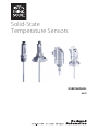
1
Solid-State Temperature Sensors USER MANUAL 837E Important User Information Because of the variety of uses for the products described in this publication, those responsible for the application and use of this control equipment must satisfy themselves that all necessary steps have been taken to assure that each application and use meets all performance and safety requirements, including any applicable laws, regulations, codes and standards. The illustrations, charts, sample programs and layout examples shown in the guide are intended solely for purposes of example. Since there are many variables and requirements associated with any particular installation, Rockwell Automation does not assume responsibility or liability (to include intellectual property liability) for actual use based upon the examples shown in this publication. Rockwell Automation publication SGI-1.1, Safety Guidelines for the Application, Installation and Maintenance of Solid-State Control (available from your local Rockwell Automation sales office), describes some important differences between solid-state equipment and electromechanical devices that should be taken into consideration when applying products such as those described in this publication. Reproduction of the contents of this copyrighted publication, in whole or part, without written permission of Rockwell Automation, is prohibited. Throughout this manual we use notes to make you aware of safety considerations: WARNING IMPORTANT ATTENTION Identifies information about practices or circumstances that can cause an explosion in a hazardous environment, which may lead to personal injury or death, property damage, or economic loss. Identifies information that is critical for successful application and understanding of the product. Identifies information about practices or circumstances that can lead to personal injury or death, property damage, or economic loss. Attentions help you identify a hazard, avoid a hazard, and recognize the consequences. SHOCK HAZARD Labels may be on or inside the equipment (for example, drive or motor) to alert people that dangerous voltage may be present. BURN HAZARD Labels may be on or inside the equipment (for example, drive or motor) to alert people that surfaces may reach dangerous temperatures. It is recommended that you save this user manual for future use. 837E Solid-State Temperature Sensors User Manual Table of Contents Safety Instructions . . . . . . . . . . . . . . . . . . . . . . . . . . . . . . . . 2 Designated Use . . . . . . . . . . . . . . . . . . . . . . . . . . . . . . . . . . . . . . . . . . . Installation, Commissioning, and Operation . . . . . . . . . . . . . . . . Operational Safety. . . . . . . . . . . . . . . . . . . . . . . . . . . . . . . . . . . . . . . . . Return . . . . . . . . . . . . . . . . . . . . . . . . . . . . . . . . . . . . . . . . . . . . . . . . . . . . 2 2 2 2 Product Identification . . . . . . . . . . . . . . . . . . . . . . . . . . . . . 3 Installation . . . . . . . . . . . . . . . . . . . . . . . . . . . . . . . . . . . . . . . 4 Dimensions . . . . . . . . . . . . . . . . . . . . . . . . . . . . . . . . . . . . . . . . . . . . . . . Process Connection . . . . . . . . . . . . . . . . . . . . . . . . . . . . . . . . . . . . . . . Installation Instructions. . . . . . . . . . . . . . . . . . . . . . . . . . . . . . . . . . . . Wiring . . . . . . . . . . . . . . . . . . . . . . . . . . . . . . . . . . . . . . . . . . . . . . . . . . . . Mating Cables . . . . . . . . . . . . . . . . . . . . . . . . . . . . . . . . . . . . . . . . . . . . . 4 5 6 8 9 Operation . . . . . . . . . . . . . . . . . . . . . . . . . . . . . . . . . . . . . . . . 9 On-site Programming . . . . . . . . . . . . . . . . . . . . . . . . . . . . . . . . . . . . . 9 Programming with Personal Computer & ReadWin 2000 . . 18 Accessories . . . . . . . . . . . . . . . . . . . . . . . . . . . . . . . . . . . . . . 20 Configuration Kit with ReadWin. . . . . . . . . . . . . . . . . . . . . . . . . . . 20 Troubleshooting . . . . . . . . . . . . . . . . . . . . . . . . . . . . . . . . . 21 Error and Warning Codes . . . . . . . . . . . . . . . . . . . . . . . . . . . . . . . . . 21 Repair. . . . . . . . . . . . . . . . . . . . . . . . . . . . . . . . . . . . . . . . . . . . . . . . . . . . 22 Change Status. . . . . . . . . . . . . . . . . . . . . . . . . . . . . . . . . . . . . . . . . . . . 22 Technical Data . . . . . . . . . . . . . . . . . . . . . . . . . . . . . . . . . . . 23 Display Version. . . . . . . . . . . . . . . . . . . . . . . . . . . . . . . . . . . . . . . . . . . 23 Nondisplay Version . . . . . . . . . . . . . . . . . . . . . . . . . . . . . . . . . . . . . . . 24 Operating Conditions . . . . . . . . . . . . . . . . . . . . . . . . . . . . . . . . . . . . 24 Pub #75054-004-10, December 2014 1 837E Solid-State Temperature Sensors User Manual Safety Instructions Designated Use The Bulletin 837E is a temperature switch for measuring and monitoring, displaying and regulating process temperatures. The device has been safely built with state-of-the-art technology and meets the applicable requirements and EC Directives. It can, however, be a source of danger if used incorrectly or for anything other than the designated use. Installation, Commissioning, and Operation Only personnel familiar with these types of products and associated machinery should plan or implement the installation, start-up, configuration, and subsequent maintenance of the Bulletin 837E temperature switch. Failure to comply may result in personal injury and/or equipment damage. Operational Safety Functional Safety The Bulletin 837E temperature switches were developed according to the standards IEC 61508 and IEC 61511-1 (FDIS). The 837E version with PNP switch output and additional analog output is equipped with fault detection and fault prevention functions within the electronics and software. This switch version can therefore be used to monitor temperatures in applications up to Safety Integrity Level 2 (SIL2). Hazardous Areas The Bulletin 837E is not approved for use in intrinsic safety (hazardous area) applications. Return Before returning a device to Rockwell Automation, be sure to remove all fluid residue. This is particularly important if the fluid is a health hazard, e.g. flammable, toxic, caustic, carcinogenic, etc. ATTENTION 2 Do not return a measuring device if you are not absolutely certain that all traces of hazardous substances have been removed, e.g. substances which have penetrated crevices or diffused through plastic. Pub #75054-004-10, December 2014 837E Solid-State Temperature Sensors User Manual Product Identification 837E-DC1BN1A1D4 Figure 1 Explanation of the nameplate - see table below 1 Catalog number 6 Current consumption 2 Series letter 7 Wiring diagram 3 Serial number 8 Operating temperature 4 Operating voltage 9 Enclosure Rating/Ingress Protection 5 Output 10 Approvals Notes: Specifications and ratings may differ from those shown in Figure 1, depending on the particular model. Refer to the product nameplate or catalog for actual ratings and specifications. The series number indicates the version of the switch. A change in the series letter does not have any effect on the compatibility—see “Change Status” section. Pub #75054-004-10, December 2014 3 837E Solid-State Temperature Sensors User Manual Installation Dimensions Display Version 42.3 (1.67) Dia. 38.5 (1.515) Dia. 38.7 (1.52) 24 (0.94) 97.1 (3.82) M12x1.0 42.1 (1.66) 6 (0.24) Dia. 6 (0.24) Dia. L Fig. 1: Dimensions Version L: 50, 100, or 200 mm M 12x1 connector as per IEC 60947-5-2 Nondisplay Version 18 (0.71) Dia. M12 71 (2.8) 14 mm Hex Nut 1/4 inch NPT Probe Length 6 (0.24) 4 Pub #75054-004-10, December 2014 837E Solid-State Temperature Sensors User Manual Process Connection The following table illustrates the versions of 837E. 1 L2 L1 2 L1 = L2 L A B C Field of application Process connection Measurement, monitoring, and control of process temperatures Measurement, monitoring, and control of process temperatures in sanitary processes Item A Version with thread process connection ANSI ¼-in. NPT (➀ = AF14) and ½-in. NPT (➀ = AF19) Item B Version with thread process connection G ¼ (➁ = AF19) and G ½ A (➁ = AF27) as per ISO 228 Item C Version with 50.8 mm (2 in.) clamp or 25.4…38.1 mm (1…1.5 in.) Thread Length L1 14.3 mm (0.56 in.) 19 mm (0.75 in.) 12 mm (0.47 in.) 14 mm (0.55 in.) — Thread Length L2 5.8 mm (0.23 in.) 8.1 mm (0.32 in.) — — Sensor length L Pub #75054-004-10, December 2014 Version L with 50, 100, or 200 mm (1.97, 3.94, or 7.87 in.) 5 837E Solid-State Temperature Sensors User Manual Installation Instructions Figure 2 Typical applications of the Bulletin 837E for temperature monitoring in pipes. ➀ 837E ➁ 837E for use in sanitary processes Mounting instructions: • Item A: Installation at angle pieces, against the direction of flow • Item B: Installation in smaller pipes, inclined against the direction of flow • Item C: Installation vertical to the direction of flow (see Figure 2, Item C). Installation of 837E by minimum of 3° inclination because of self draining. • The digital display can be electronically rotated 180°—see “Operation” section. • The housing can be rotated up to 310° for optimal readability and ease of wiring. 6 Pub #75054-004-10, December 2014 837E Solid-State Temperature Sensors User Manual Installation in Hygienic Processes Shaped gasket Companion connection Figure 3 Mounting instructions for installation in hygienic processes The matches for the process connections as well as the gaskets are not included in the scope of delivery of this assembly. • Care should be taken by the user in the execution of the welding on the process side: • Suitable weld material • Flush welding or with welding radius > 3.2 mm. • Absence of pits, folds, crevices. • Ground and polished surface (Ra ≤ 0.8 μm). As a general rule, the thermometers should be installed in such a way that does not adversely affect their cleanability. Pub #75054-004-10, December 2014 7 837E Solid-State Temperature Sensors User Manual Wiring Display Version The 837E is a DC voltage switch with two PNP outputs or a single PNP output with a 4…20 mA analog output. Both options feature an M12 (micro) connector. + 2 1 3 4 Load 1 Load 2 + 12…30V DC 2 1 3 4 12…30V DC Load 2 4…20 mA – – Figure 4 .Bulletin 837E with two PNP switch outputs or one PNP output with 4…20mA analog output Nondisplay Version The 837E nondisplay version is offered with 4…20 mA analog output with PCprogrammable transmitter. Pin No. 2 1 10…35V DC (4…20 mA) 1 2 3 0V (4…20 mA) 4 3 4 Explanation Power supply 10…35V DC, current output 4…20 mA Connection of PC configuration cable, shortened pin Power supply 0V DC, current output 4…20 mA Connection of PC configuration cable, shortened pin Wire Color Brown White Blue Black Programming cable adaptor 836-NSRT required for programming with ReadWin software kit 836E-NSR. 8 Pub #75054-004-10, December 2014 837E Solid-State Temperature Sensors User Manual Mating Cables 2 m (6.5 ft) PVC cable with 4-pin micro (M12 x 1) connector and ratcheted epoxy-coated zinc coupling nut. Catalog Number: 889D-F4AC-2 889D-F4AC-2 2 m (6.5 ft) PVC cable with 4-pin micro (M12 x 1) right-angle connector and ratcheted epoxy-coated zinc coupling nut. Catalog Number: 889D-R4AC-2 Note: Other cable lengths are available and shielded cables may be required for some analog output applications – refer to the On-Machine Connectivity catalog. 889D-R4AC-2 Operation On-site Programming The Bulletin 837E is programmed via three push buttons. The digital display and the light emitting diodes (LEDs) assist in the navigation through the operating menu. Operating key E LED for status Green = ok Red = error Red/green blinking = warning 22.07 bar Digital display Illumination white = OK Illumination red = error/fault Yellow LEDs for switching states LED on = switch closed LED off = switch open Communications jack for personal computer Figure 5 Location of operating keys and display elements Pub #75054-004-10, December 2014 9 837E Solid-State Temperature Sensors User Manual Navigating through the programming menu Refer to the menu structure in Figure 6 on the following page. The section labelled A refers to Function groups The section labelled B refers to the individual Functions within each Function group The section labelled C identifies the possible values for each function ➀ To enter the operating menu: • Press and hold the E key for longer than 3 sec. ➁ Once in programming mode (BASE will be displayed), toggle between the Function groups with the + and − keys ➂ To enter the Function group, press the E key ➃ To toggle between functions, repeatedly press the E key (Note that repeatedly pressing the E key will return you to the Function group. • Then press the E key to return to the “Function” option ➄ Once on the desired function, use the + or − key to change the function value ➅ Press E to accept the function value ➆ To save changes, press and hold the E key for longer than 3 sec. • Once in SAVE, choose YES or NO with the + or − key • Confirm with the E key (sensor will go through a start-up routine before entering operating mode) • Warning code 210 (W210) will appear on the display to indicate a change in configuration (see “Error and warning codes” section). ATTENTION Changes take effect only when you choose YES when asked to save the data. 10 Pub #75054-004-10, December 2014 837E Solid-State Temperature Sensors User Manual Structure of the programming menu for 2x switch outputs The chart below illustrates the structure of the programming menu. B A BASE - + - + OUT2 - + SERV - E UNIT + °C ZERO + 0.0 + + °F + K + PVRO + SP + SPRO GET .Z + 0.0 DISP + PV TA U + 0. 0 DESI + NO + YES + WINC + HYNC + WINO + HYNO + HYNC + WINO + HYNO E FUNC OUT C SP + 0.0 RSP + 0.0 TSP + 0. 0 TRSP + 0. 0 E FNC2 + WINC SP2 + 0.0 RSP2 + 0.0 TSP2 + 0.0 TRS2 + 0.0 E LOCK + 0 CODE + 0 PRES + NO REV’C + 0 LST’A + 0 SIM + OFF + OPEN + CLOS SIM2 + OFF + OPEN + CLOS MAX’ + 0.0 MIN’ + 0.0 + OFF + OFFR + YES Figure 6 Programming menu: A=function groups, B=functions, C=settings Pub #75054-004-10, December 2014 11 837E Solid-State Temperature Sensors User Manual Structure of the programming menu for 1x switch output and 1x analog output (4…20 mA) The chart below illustrates the structure of the programming menu. B A BASE - + - + OUT2 - + 4…20 - + SERV - E UNIT + °C ZERO + 0.0 + + °F + K + PVRO + SP + SPRO + OFF GET.Z + 0.0 DISP + PV TA U + 0.0 DESI + NO + YES + WINC + HYNC + WINO + HYNO + 4…20 + HYNC + WINO + HYNO + 4…20 + MAX + HOLD E FUNC OUT C SP + 0.0 RSP + 0.0 TSP + 0.0 TRSP + 0.0 E FNC2 + WINC SP2 + 0.0 RSP2 + 0.0 TSP2 + 0.0 TRS2 + 0.0 E SETL + 0.0 SETU + 0.0 GET’L + 0.0 GET’U + 0.0 FCUR + MIN + OFFR E LOCK + 0 CODE + 0 PRES + NO REV’C + LST’A + 0 SIM + OFF + OPEN + CLOS + 3.5 + 4 + 8 +… SIM2 + + OPEN + CLOS + 3.5 + 4 + 8 +… + YES 0 OFF MAX’ + 0.0 MIN’ + 0.0 (4…20) Figure 7 Operating menu: A function groups, B functions, C settings 12 Pub #75054-004-10, December 2014 837E Solid-State Temperature Sensors User Manual Basic Settings Base Pub #75054-004-10, December 2014 Basic Settings Unit of measure Select technical unit: °C °F K Configure zero point Position adjustment: within ±20% of the upper range limit Accept zero point Current value as zero point (max. ±20% of the upper range limit) Display PV: measured value display PVRO: measured value display rotated 180° SP: set switch point display SPRO: set switch point display rotated 180° OFF: display off OFFR: display off rotated 180° Damping: display value, output signal 0…40 sec. DESINA Connection in accordance with DESINA guidelines 13 837E Solid-State Temperature Sensors User Manual Output setting • Hysteresis mode The hysteresis mode enables two-point control via a hysteresis. Depending on the temperature T, the hysteresis can be set via the switch point SP and the reset point RSP. • Window mode The window mode allows for the monitoring of a temperature range. • Analog output mode The analog output mode returns a 4…20 mA signal proportional to the measured value. The upper and lower range values can be set by the user. • Each switch point can be selected as Normally Open (N.O.) or Normally Closed (N.C.) • Delay times for switch point SP and switch-back point can be set in increments of 1 s. By this means, undesirable temperature peaks of short duration or of high frquency can be filtered out. 1 2 p p SP SP RSP RSP t 1 0 3 1 0 4 t 3 4 1 0 1 0 Figure 8 ➀ Hysteresis mode, ➁ Window mode, ➂ Switch status of N.O. contact, ➃ Switch status of N.C. contact SP = switch point; RSP = reset point 14 Pub #75054-004-10, December 2014 837E Solid-State Temperature Sensors User Manual OUT/OUT2 Output/Output 2 Switching mode HYNO: Hysteresis/NO contact HYNC: Hysteresis/NC contact WINO: Window/NO contact WINC: Window/NC contact 4…20 mA: Analog mode (analog output versions only) Switch point value Switch point 0.5…100% URL in increments of 0.1 °C Reset point value Reset point 0…99.5% URL in increments of 1 °C Switch point delay Delay time 0…99 sec. in increments of 1 sec. Reset point delay Delay time 0…99 sec. in increments of 1 sec. Min. distance between SP and RSP:0.5 °C/K (0.9 °F) Pub #75054-004-10, December 2014 15 837E Solid-State Temperature Sensors User Manual 4…20 Analog Output Value for 4 mA (LRV) Enter lower range value in increments of 0.1 °C Value for 20 mA (URV) Enter upper range value in increments of 0.1 °C Temperature applied for 4 mA (LRV) Use measured temperature as lower range value Temperature applied for 20 mA (URV) Use measured temperature as upper range value Error current Current value in event of error: MIN = ≤ 3.6 mA MAX = ≥ 21.0 mA HOLD = last value Range of adjustment: LRL = Lower Range Limit; URL = Upper Range Limit; LRV = Lower Range Value; URV = Upper Range Value Min. distance between SETL and SETU: 20 °C/K (36 °F) 16 Pub #75054-004-10, December 2014 837E Solid-State Temperature Sensors User Manual Service Function Setting SERV Pub #75054-004-10, December 2014 Service Functions Security locking/password protection Enable password protection Password/code entry Select code 1…9999 0 = no locking Reset Reset all entries to the factory setting Revision counter Increases by 1 with each configuration Last device status Displays the last device status to occur ≠0 Simulation output 1 or 2 OFF: No simulation OPEN: Switch output open CLOS: Switch output closed 3.5: Simulation values for analog output in mA (3.5/4.0/8.0/12.0/ 16.0/20.0/21.7) Max. indicator Display of max. measured process value Min. indicator Display of min. measured process value 17 837E Solid-State Temperature Sensors User Manual Programming with Personal Computer & ReadWin 2000 The 837E can also be configured via personal computer and ReadWin software. An additional configuration kit with a conversion cable (Cat. No. 836E-NSR) is required to interface the USB port of the PC to the programming port of the temperature sensor, as shown below. USB Figure 9 Programming with PC Personal computer with ReadWin configuration software Configuration kit (836E-NSR) Bulletin 837E with programming port Note: For nondisplay version choose sensor type “PT100” in standard settings. Programming cable adaptor 836E-NSRT is required for 837E nondisplay version when using ReadWin 2000. 18 Pub #75054-004-10, December 2014 837E Solid-State Temperature Sensors User Manual Figure 10 Sensor configuration with ReadWin Additional Operating Options In addition to the operating options listed in the “On-site programming” section, the ReadWin configuration software provides an additional function group with further information on the Bulletin 837E: Function Group SERV Description Number of switch changes for output 1 Number of switch changes for output 2 Device status Last error to occur Pub #75054-004-10, December 2014 19 837E Solid-State Temperature Sensors User Manual Function Group INFO Description Tag number Switch serial number Sensing element serial number Electronics serial number Series number Hardware version Software version Accessories Configuration Kit with ReadWin The configuration kit (Cat No. 836E-NSR) consists of a software CD and a conversion cable which interfaces the USB port of the PC to the four-pin programming port on the sensor face. USB ReadWin® 2000 software is also available free of charge via download from http://ab.rockwellautomation.com, select Product Directory/Sensors & Switches/ Condition Sensors/Pressure Sensors/Solid-State Pressure Switches/Resources. Reference “Other Resources” and select “ReadWin Configurator for Windows™ 2000. zip. 20 Pub #75054-004-10, December 2014 837E Solid-State Temperature Sensors User Manual Troubleshooting Error and Warning Codes If an error occurs in the electronics, the color of the status LED changes from green to red and the display shows an error or warning code, as outlined below: • E-code for errors In the event of an error message, the measured value is unreliable. • W-code for warnings In the event of a warning, the measured value is still reliable. Error Codes Code Explanation E011 Device configuration faulty E012 Error in measurement E015 Device error (internal) E019 Power supply has undervoltage/overvoltage E020 Device error (internal) E021 Device error (internal) E022 USB supply voltage E025 Switching contact 1 is not open, although it should be open E026 Switching contact 2 is not open, although it should be open E040 Device error (internal) E042 Output current cannot be generated. Possible cause: analog output not connected or open circuit E044 Excessive output current drift (±0.5 mA) Pub #75054-004-10, December 2014 21 837E Solid-State Temperature Sensors User Manual Warning Codes Code Explanation W107 Simulation active W202 Temperature outside the sensor range W209 Device start-up W210 Configuration modified W212 Sensor signal outside the permitted range W250 Number of switch cycles exceeded W270 Short-circuit at output 1 W280 Short-circuit at output 2 Repair Bulletin 837E temperature switches are not repairable. Change Status The release number on the nameplate and in the Operating Instructions indicates the change status of the device: XX.YY.ZZ (example 01.02.01). XX YY ZZ 22 Change in the main version. Compatibility no longer provided. Device and Operating Instructions change. Change in functionality and operation. Compatibility provided. Operating Instructions change. Troubleshooting and internal modifications. Operating Instructions do not change. Pub #75054-004-10, December 2014 837E Solid-State Temperature Sensors User Manual Technical Data Display Version Power Supply Supply voltage • DC voltage version 12…30 V DC Current consumption • Without load < 60 mA, with reverse polarity protection Power supply failure • Behavior in case of overvoltage (> 30 V) The device works continuously up to 34V DC without any damage. No damage is caused to the device in case of a short-term overvoltage up to 1 kV (as per EN 61000-4-5). If the supply voltage is exceeded, the properties specified are no longer guaranteed. • Behavior in case of undervoltage If the supply voltage drops below the minimum value, the device switches off (status as if not supplied with power = switch open). Output Switching capacity • • • • • Switch status ON: Ia ≤ 250 mA Switch status OFF: Ia ≤ 1 mA Switching cycles: > 10,000,000 Voltage drop PNP: ≤ 2 V Overload protection Automatic load testing of switching current; output is switched off in case of overcurrent, the switching current is tested again every 0.5 sec.; max. capacitance load: 14 μF for max. supply voltage (without resistive load). Load (analog output) • Max. (Vsupply - 6.5 V) / 0.022 A Signal on alarm • Analog output: ≤ 3.6 mA or ≥ 21.0 mA adjustable (if setting ≥ 21.0 mA the output is ≥ 21.5 mA) • Switch outputs: in safe state (switch normally open) Pub #75054-004-10, December 2014 23 837E Solid-State Temperature Sensors User Manual Nondisplay Version Power Supply Supply voltage • 10…35V DC Current consumption • 23 mA Output Output signal • 4…20 mA Maximum load • Max. (Vsupply - 10V)/0.023 A Operating Conditions • Any orientation Operating conditions: Environment • Ambient temperature range: -40…+85 °C (-40…+183 °F) • Storage temperature: -40…+85 °C (-40…+183 °F) • Degree of protection: IP65 (optional IP66, depending on used connector) Operating conditions: Process • Process temperature limits: -50…+150 °C (-58…+302 °F) IMPORTANT There are restrictions to the maximum process temperature that can be monitored based on the ambient temperature—see below. Max. Ambient Temperature Max. Process Temperature up to 25 °C (77 °F) no restriction up to 40 °C (104 °F) 135 °C (275 °F) up to 60 °C (140 °F) 120 °C (248 °F) up to 85 °C (185 °F) 100 °C (212 °F) • Process pressure limits: p/T load diagram per DIN 43763 24 Pub #75054-004-10, December 2014 837E Solid-State Temperature Sensors User Manual Figure 11 p/T load diagram L = insertion length vL = velocity air vW = velocity water Pub #75054-004-10, December 2014 25 837E Solid-State Temperature Sensors User Manual Notes 26 Pub #75054-004-10, December 2014 Publication 75054-004 Ver 10 — December 2014 Supersedes Publication 75054-004 Ver 09 — August 2014 © 2014 Rockwell Automation, Inc. Printed in the USA.