1
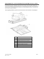
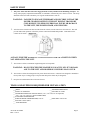
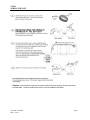
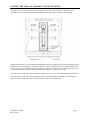
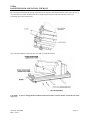
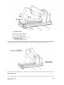
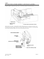
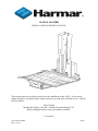
AL625 & AL625HD INSTALLATION & OWNER’S MANUAL These instructions are provided to assist you in the installation of the AL625. If you require further assistance, our trained staff is ready to provide you with quick, efficient service. Call our toll-free number: 866.378.6648 Monday thru Friday, 8:00 AM – 8:00 PM (Except holidays) E.S.T Before calling please have your serial number available. 2012 Harmar AL625 & AL625HD REV: 1-24-12 Page 1 TABLE OF CONTENT SECTION TITLE PAGE # REQUIREMENTS AND CONSIDERATIONS BEFORE INSTALLATION SAFETY FIRST ……………………………………3 …………………………………………………………………………………………………….4 TOOLS AND SUPPLIES REQUIRED FOR INSTALLATION ……………………………………………………. 4 STEP 1 STEP 2 STEP 3 STEP 4 STEP 5 STEP 6 STEP 7 STEP 8 STEP 9 STEP 10 STEP 11 STEP 12 ELECTRICAL WIRING INSTALLING THE MOUNTING BARS MOUNTING THE TRACKER DIRECTLY TO THE VEHICLE’S FLOOR POSITION THE TROLLEY ASSEMBLY ON THE MOUNTING BARS ATTACH LEVELING FEET TO THE TROLLEY ASSEMBLY POSITION THE TROLLEY ASSEMBLY AND BOLT IT DOWN RAISE THE BOOM AND INSTALL THE BOLT MOUNTING THE PLATFORM ASSEMBLY TO THE TROLLEY ASSEMBLY CHECK CLEARANCES WITHOUT LOAD ADJUST PLATFORM ANGLE TO SUIT LOAD (if necessary) ADJUSTING THE VERTICAL – HORIZONTAL TRANSITION (if necessary) CONFIRMING HOME POSITION AND LOCKING PIN ALIGNMENT INSTALLING THE STRAP SYSTEM 5 6 7 8 9 10 11&12 13 14 15 16 17 18-19 FUSE FOR RF REMOTE CONTROL CIRCUIT ………………………..………………………………………… 20 TRAINING THE END-USER ……………………………………………………………………………………… 20 MAINTAINING THE LIFT ……………………………………………………………………………………….. 20 TROUBLESHOOTING ……………………………………………………………………………………………. 21 ELECTRONIC CONTROL BOX WIRING DIAGRAM ...…………………………..……………………………. 22 FOR YOUR RECORDS SALESPERSON______________________________________ TELEPHONE________________________________________ PURCHASE DATE_________________________________LIFT SERIAL #______________________________________ CUSTOMER #_____________________________________ORDER #___________________________________________ AL625 & AL625HD REV: 1-24-12 Page 2 REQUIREMENTS AND CONSIDERATIONS BEFORE INSTALLATION The Freedom Lift Tracker is designed to work with a variety of vehicles. Since each vehicle is different, the success of each installation is largely determined by the care and forethought of the installer. Before beginning any installation, please read through this manual to familiarize you with the installation procedure. This will save you time and result in a quality installation. Before beginning installation, open the boxes and check that the contents match those on the packing list. ITEM AL625 & AL625HD REV: 1-24-12 DESCRIPTION 1 TROLLEY ASSEMBLY 2 PLATFORM ASSEMBLY 3 INTERLOCK INSTALL KIT (not shown) 4 CONTROL PENDANT (not shown) 5 HARDWARE KIT (not shown) 6 REMOTE CONTROL (not shown) 7 BATERY CHARGER (not shown) 8 MOUNTING BARS (not shown) Page 3 SAFETY FIRST 1. The power chair must have the brake engaged and be securely attached to the lift during transport. The straps, when properly adjusted and maintained, are intended to constrain the power chair or scooter. The straps should be checked to make certain they are in good condition before each use. WARNING: FAILURE TO ENGAGE THE BRAKE AND SECURELY STRAP THE POWER CHAIR/SCOOTER TO THE LIFT DURING TRANSPORT COULD RESULT IN SERIOUS PERSONAL INJURY OR DAMAGE TO THE LIFT, THE POWER CHAIR, AND VEHICLES. 2. After the Power Chair/Scooter has been lifted into the vehicle, turn the control cut-off switch off. This will prevent inadvertent operation of the lift by remote control and/or hand held pendant. Remember for the control cut-off switch – “RED IS ON.” ALWAYS PUSH THE POWER CUT-OFF SWITCH TO THE OFF POSITION WHEN NOT OPERATING THE LIFT. 3. The Tracker lift has a maximum weight lifting limit of 350 pounds. WARNING: DO NOT EXCEED THE MAXIMUM CAPACITY OF LIFT OR DAMAGE TO THE LIFT AND/OR SERIOUS INJURIES MAY OCCUR. 4. The Tracker lift has been designed to lift power chairs and scooters. It has not been designed or intended to lift any other object. Lifting people or objects other than power chairs may be dangerous. 5. Keep the area underneath of the lift clear at all times. TOOLS AND SUPPLIES REQUIRED FOR INSTALLATION ___DRILL ___ASSORTED DRILL BITS ___SMALL FLASHLIGHT ___ELECTRICAL TAPE ___ASSORTED WRENCHES AND SOCKETS (7/16”, 9/16” and 3/4" are important) ___ 5/32”, 3/16, 1/4”, and 5/16” ALLEN WRENCHES ___STANDARD SCREWDRIVER ___PHILLIPS HEAD SCREWDRIVERS, #1 & #2 ___PORTABLE VACUUM ___SILICON CAULK (RTV) ___ TAPE MEASURE AL625 & AL625HD REV: 1-24-12 Page 4 STEP 1 WIRING THE LIFT AL625 & AL625HD REV: 1-24-12 Page 5 STEP 2 INSTALLING THE MOUNTING BARS The Tracker rests on top of a pair of mounting bars, which together with the U-bolt brackets, allow installation using the vehicle’s existing seat attachment points. To install the Mounting Bars: a) Position the (2) MOUNTING BARS over the vehicle’s rear seat attachment points. b) Attach the (4) “U” BOLTS provided, around the seat attachment points and the MOUNTING BARS. Depending on the vehicle’s seat hooks, you may need to add the ½” long tube spacers provided between the 3/8-16 Hex Nuts and the plate (see photo below), in order for the nuts to be on the U-bolt threads. Hand-tighten the bolts enough to hold them in place, but loose enough to slide the bars side to side for adjustment. c) Center the threaded holes in the MOUNTING BARS with the sides of the cargo area to center the lift. Example: Mounting Bars Installed AL625 & AL625HD REV: 1-24-12 Page 6 NOTE: IF YOU ARE INSTALLING THE TRACKER INTO A DODGE GRAND CARAVAN (OR SIMILAR CHRYSLER VAN), READ THE INSTRUCTIONS PAGE 13 ABOUT POSITIONING THE TRACKER TO LEAVE THE SPARE TIRE RELEASE BOLT ACCESSIBLE. AL625 & AL625HD REV: 1-24-12 Page 7 MOUNTING THE TRACKER DIRECTLY TO THE VEHICLE’S FLOOR The Tracker may be installed by bolting the Side Mounting Rails of the Trolley Assembly to the vehicle’s floorboard if there is a suitable mounting surface and are no obstructions (fuel tank, brake lines, etc.) WARNING: CHECK FOR VEHICLE COMPONENTS UNDER THE FLOORBOARD BEFORE DRILLING ANY HOLES. CHECK THE AREA BENEATH THE VEHICLE IN THE INTENDED INSTALLATION LOCATION TO BE SURE YOU WILL NOT PIERCE OR CONTACT THE FUEL TANK, ELECTRICAL WIRING, BRAKE LINES, ETC. CHECK FOR RUST DAMAGE OR COLLISION REPAIR THAT MAY COMPROMISE THE VEHICLE’S STRUCTURAL INTEGRITY. Fold back or remove the carpet in the area to expose the metal floorboard. The Trolley Assembly must be mounted to a relatively flat surface. Small irregularities, such as stiffening channels, may be shimmed with washers when the Trolley Assembly is bolted down. On most installations, the carpet can be folded back into place and trimmed around the Side Mounting Rails so that it will be captured neatly against the Trolley Assembly. Use your best judgment and strive for a neat installation. Place the Trolley Assembly in the desired position on the floor of the vehicle’s cargo area and mark the four hole locations with a 3/8” center punch. Remove the Trolley Assembly and drill the four holes for the mounting bolts using a 3/8” drill bit. BE VERY CAREFUL NOT TO DAMAGE ANYTHING ON THE UNDERSIDE OF THE TRUNK WHEN THE DRILL BIT PUNCHES THROUGH THE METAL FLOOR. Install the Trolley Assembly with the 3/8” X 2.5” Bolts, 3/8” Flat Washers, Hex Washer Plates and 3/8” Locking Nuts provided. If shims are necessary (to compensate for irregularities in the trunk floor or to level the Trolley Assembly) use additional 3/8” ID Flat Washers (not included). Attach a 3/8” Washer and a 3/8” Self-Locking Nut to the Hex Washer Plate and Bolt from the underside of the vehicle and tighten securely. At this time, the washers and nuts that mate to the underside of the vehicle should be sealed with silicone sealant to prevent moisture from entering the holes and rusting the vehicle’s floor or Trolley Assembly. CAUTION: FAILURE TO SECURELY FASTEN ALL THE BOLTS MAY RESULT IN DAMAGE TO THE LIFT OR VEHICLE’S FLOOR. THIS CONDITION MAY CAUSE THE UNIT TO FAIL UNDER LOAD, THUS RISKING PERSONAL INJURY TO THE OPERATOR AND DAMAGE TO THE POWER CHAIR/SCOOTER AND/OR TO THE VEHICLE. STEP 3 AL625 & AL625HD REV: 1-24-12 Page 8 POSITION THE TROLLEY ASSEMBLY ON THE MOUNTING BARS Place the trolley assembly into the vehicle, laying it on top of the mounting bars. Arrange the trolley assembly so it is facing as shown in the figure below. STEP 4 AL625 & AL625HD REV: 1-24-12 Page 9 ATTACH LEVELING FEET TO THE TROLLEY ASSEMBLY Place the adjusting feet (found in the hardware bag) in the holes of the SIDE MOUNTING RAILS, near the front of the Tracker. If the floor of the vehicle is level all the way, insert the feet with a 3/8 washer on each directly through the mounting rail as shown in the figure below. Secure the mounting feet with a 3/8 washer and Nylock nut on top. If you need to elevate the feet in order to level the trolley assembly, put a 3/8-16 hex jam nut and 3/8 washer onto the leveling foot first, then insert the threaded portion of the foot through the side mounting rail, as shown in the figure below. If removing the High threshold Feature you will have to saw off threads of leveling feet to clear platform. Turn the additional 3/8-16 jam nut & nylock nut to adjust the height of each leveling foot. Adjust the height of the feet so that the weight of the Trolley Assembly is evenly distributed on both of the mounting bars and leveling feet. Next- set the final position of the Trolley Assembly in the cargo area and tighten down all of the nuts and bolts. STEP 5 AL625 & AL625HD REV: 1-24-12 Page 10 POSITION THE TROLLEY ASSEMBLY AND BOLT IT DOWN Align the front of the Trolley Assembly as far rearward in the opening of the cargo area as possible. This is important so that the Tracker PLATFORM ASSEMBLY will clear the vehicle’s bumper when operating. Slide the trolley assembly on the mounting bars and adjust its position, aligning the holes in the Side mounting rails with the holes in the mounting bars. Check the distance from the side mounting rails of the trolley assembly to the sides of the cargo area, to make sure the trolley assembly is centered. To adjust the side-to-side distance, loosen the 3/8 nuts on the U-bolts and slide the trolley assembly & mounting bars to one side or the other. Secure the side mounting rails to the mounting bars using the (4) 3/8-16 x 5/8” bolts; hand tighten only at this point. Do one final check of the side-to-side alignment and distance to the threshold/sill, adjusting if needed, and then tighten down all of the hex nuts on the U-bolts, and the 3/8 bolts on the mounting bars. AL625 & AL625HD REV: 1-24-12 Page 11 STEP 6 RAISE THE BOOM AND INSTALL THE BOLT Have an assistant hold the front boom up off the lead screw OR put a small board under the front boom to prop it up off of the lead screw/collar assembly; this will avoid plowing the front boom into the end of the track if you accidentally press OUT instead of IN. Now, using the pendant to control the lift, press “IN” to extend the actuator. CAUTION: As you are raising the lift, watch the boom head to make certain it will not contact the roof of the cargo area. AL625 & AL625HD REV: 1-24-12 Page 12 After the actuator is extended, lift the Front Boom Weldment and swing the Upper Boom Frame onto the Front Boom Weldment and align the holes; put the bolt in. Secure the bolt with the nylon insert locknut. Move unit out approximately 2” & remove (2) wood blocks located in tracks used to prevent shipping damage. Next you will determine if you should remove the High Threshold Kit that comes with your Trolley Assembly. AL625 & AL625HD REV: 1-24-12 Page 13 STEP 7 MOUNTING THE PLATFORM ASSEMBLY TO THE TROLLEY ASSEMBLY Using the pendant to control the lift, press “OUT” to move the lift out & down to the position shown. With the help of an assistant – Lift the platform assembly sliding the deck pivot vertical tube into the slot on the boom head on the trolley assembly. Use the 2 lower holes on the Vertical Tube. Insert the 3/8-16 Hex Head Cap Screws (Bolts) and washers; tighten the 3/8-16 nyloc nuts to hold the tube in place. AL625 & AL625HD REV: 1-24-12 Page 14 STEP 8 CHECK CLEARANCES WITHOUT LOAD Operate the Tracker without a load and check the clearance of the platform over the bumper and threshold of the vehicle. Check the side-to-side clearances. To adjust the side-to-side distance, loosen the 3/8 nuts on the U-bolts and slide the trolley assembly & mounting bars to one side or the other. AL625 & AL625HD REV: 1-24-12 Page 15 STEP 9 ADJUST PLATFORM ANGLE TO SUIT LOAD – Power Chair or Scooter You will need a ¼” socket wrench to adjust the set screws. Adjust the platform so that it is level while the customer’s power chair/scooter is on it. AL625 & AL625HD REV: 1-24-12 Page 16 STEP 10 ADJUSTING THE VERTICAL – HORIZONTAL TRANSITION The relay circuit in the Tracker is designed to end lifting and begin horizontal travel into the vehicle when the limit switch in the back boom weldment is contacted. The Tracker is shipped with a factory setting for this limit switch. Depending on the weight of the power chair/scooter you may need to adjust the point where the lift ends, especially if the load being carried is near the weight limit of 350 pounds. To adjust, loosen the jam nut on the screw, and turn the contact screw inward to increase the upward lift, OR outward to reduce the upward lift. AL625 & AL625HD REV: 1-24-12 Page 17 STEP 11 CONFIRMING HOME POSITION AND LOCKING PIN ALIGNMENT The Tracker is in its home position when the horizontal motion is completed. The movement stops when the stop rod (mentioned in Step 11) contacts the back end of the trolley assembly, and activates a limit switch. When the Tracker is in its home position, it is important that the alignment pins are captured in the holes in the front plate/high threshold plate (see figure below) If the pins are not captured in the holes, adjust the angle of the platform (Step 12) Make certain you adjust the angle of the platform with the load (power chair/scooter) on. WARNING: THE ALIGNMENT PINS SECURE THE PLATFORM, AND TOGETHER WITH THE STRAPS, SECURE THE POWER CHAIR/SCOOTER TO THE TROLLEY ASSEMBLY DURING TRANSPORT. AN UNSECURED POWER CHAIR/SCOOTER CAN CAUSE SERIOUS INJURIES. AL625 & AL625HD REV: 1-24-12 Page 18 STEP 12 INSTALLING THE STRAPS FOR THE CUSTOMER’S POWER CHAIR/SCOOTER Buckle (above) Latch Plate & Adjustable Strap (below) In general, Power Chairs will use straps mounted near the center of the platform, and for Scooters the straps will be mounted off to one side. Locate the straps on the platform where they will be able to buckle across the seat of the customer’s power chair or scooter. Note: It is strongly recommended that the buckle be attached to the side closest to the vehicle (van, minivan) so that the adjustable strap is easy to reach. POWER CHAIR SCOOTER Installing Straps in the Center Positions Installing the side near the trolley assembly. Use 5/16 – 18 x 1” Button Head Socket Screw, 5/16 – 18 nylon insert lock nut, and one 5/16 SAE flat washers. AL625 & AL625HD REV: 1-24-12 Page 19 Installing the side towards the outside of the vehicle. Use the 5/16 – 18 x 1.25” flat head screw, five 5/16 SAE flat washers (to space the strap away from the deck), another 5/16 SAE flat washer and finally a 5/16 – 18 nylon insert lock nut to secure the metal plate of the buckle side of the strap as shown. Installing Straps off to the side in the Loop Positions Installing the loop, on the side near the trolley assembly. Use 3/8 – 16 x 1.5” Hex Cap Screw, 3/8 – 16 nylon insert lock nut, and two 3/8 x 1.25 fender washers, as shown below: Installing the side towards the outside of the vehicle. Use the 3/8 – 16 x 1.5” Hex cap screw, two 3/8 SAE flat washers, two 3/8 x 1.25 fender washers, and a 3/8 – 16 nylon insert lock nut to secure the metal plate of the latch plate to the loop as shown below: The fender washers must contact the loop. AL625 & AL625HD REV: 1-24-12 Page 20 FUSE FOR RF REMOTE CONTROL CIRCUIT If the Remote Control is not working, check the fuse to see if it is blown. Replace the fuse if necessary. If the Remote Control unit still does not function, there may be another problem with the Tracker - check the operation of the Tracker using the hand held pendant. TRAINING THE END-USER - Review all of the SAFETY ISSUES. - Explain how the Lift is wired. - Explain the location and operation of the self-resetting fuse in the electrical circuit. - Review the operation of the lift as described in the USER’S MANUAL. MAINTAINING THE LIFT a) CLEANING: KEEP THE TRACKS CLEAR OF FOREIGN OBJECTS Even small stones/gravel inside the tracks can interfere or stop the operation of your Tracker b) Inspect the straps for wear or fraying with each use. c) Inspect the side-to-side clearances and over the bumper & threshold clearances with each use. d) MONTHLY: Check all mounting hardware for tightness and signs of wear due to vehicle aging, rust, etc. e) TWICE A YEAR: Lubricate the lead screw with a small amount of wheel bearing grease. Lubricate all bearing points and moving parts using wheel-bearing grease. AL625 & AL625HD REV: 1-24-12 Page 21 TROUBLESHOOTING CHART SYMPTOM Lift does not work POSSIBLE CAUSE Control cut-off switch is off. Power cord is unplugged from lift. Vehicle battery not connected or is dead. Mobile Power battery pack is weak or “dead” Pendant not plugged in Lift runs slowly Plug the power cord into the vehicles wire harness, see page 7 Check the battery connections; charge the battery. Check LED on Mobile Power battery pack; charge if it is red, see page 6. Plug pendant in Trolley not moving on tracks Foreign objects in tracks; clean out the tracks RF remote batteries weak/”dead” RF fuse blown Try the hand held pendant Replace batteries in RF remote unit Inspect RF fuse, replace if needed Weak vehicle battery or Mobile Power battery pack. Charge Mobile Power battery pack Charge vehicle’s battery / run vehicle to charge it. Load is too heavy. Only lift power chairs under 350 pounds. Remove any heavy personal items stored on Power Chair/Scooter. Re-adjust the strap. Power chair too loose or too tight on the lift Improperly adjusted strap Loud mechanical clicking sound after the lifting is complete Actuator (electric cylinder) is clutching out Misalignment of lift, platform not clearing bumper, rubbing into vehicle Alignment hardware not tightened. Improper alignment during installation. AL625 & AL625HD REV: 1-24-12 SOLUTION Turn the switch on. “RED IS ON”, see page 3 See if problem occurs without Power Chair/Scooter on the platform. Adjust the contact screw on “boom mounted limit switch” Inspect and adjust the lift alignment. Page 22 ELECTRONIC CONTROL BOX WIRING DIAGRAM AL625 & AL625HD REV: 1-24-12 Page 23 Manual Overrides In the case that the lift cannot be moved electrically it is equipped with two manual overrides. The actuator controls the up and down function. Look down into the tower the top of the actuator will be visible, locate the plastic plug and remove it. Once this plug is removed take a 5/16” hex tool and rotate clockwise to raise or counter clockwise to lift. AL625 & AL625HD REV: 1-24-12 Page 24 Second manual override is for the motor that operates the in and out function. Locate the manual override sticker by the on/off switch and remove it. Recessed in will be the rear of the motor with a 1” hole and a small hex stud visible. A 1/8” hex tool is needed for this manual operation. AL625 & AL625HD REV: 1-24-12 Page 25 AL625 & AL625HD REV: 1-24-12 Page 26 AL625 & AL625HD REV: 1-24-12 Page 27 AL625 & AL625HD REV: 1-24-12 Page 28