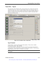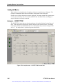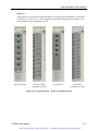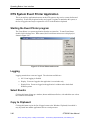
1
Artisan Technology Group is your source for quality new and certified-used/pre-owned equipment • FAST SHIPPING AND DELIVERY • TENS OF THOUSANDS OF IN-STOCK ITEMS • EQUIPMENT DEMOS • HUNDREDS OF MANUFACTURERS SUPPORTED • LEASING/MONTHLY RENTALS • ITAR CERTIFIED SECURE ASSET SOLUTIONS SERVICE CENTER REPAIRS Experienced engineers and technicians on staff at our full-service, in-house repair center WE BUY USED EQUIPMENT Sell your excess, underutilized, and idle used equipment We also offer credit for buy-backs and trade-ins www.artisantg.com/WeBuyEquipment InstraView REMOTE INSPECTION LOOKING FOR MORE INFORMATION? Visit us on the web at www.artisantg.com for more information on price quotations, drivers, technical specifications, manuals, and documentation SM Remotely inspect equipment before purchasing with our interactive website at www.instraview.com Contact us: (888) 88-SOURCE | [email protected] | www.artisantg.com User Manual p OTS Optical Test System Multi-rate (155Mb/s to 2.5Gb/s) SONET/SDH/DWDM module 071-1044-00 Artisan Technology Group - Quality Instrumentation ... Guaranteed | (888) 88-SOURCE | www.artisantg.com Copyright © Tektronix, Inc. 2001. All rights reserved. Licensed software products are owned by Tektronix or its suppliers and are protected by United States copyright laws and international treaty provisions. Tektronix products are covered by U.S. and foreign patents, issued and pending. Information in this publication supersedes that in all previously published material. Specifications and price change privileges reserved. Tektronix, Inc. 14200 SW Karl Braun Drive Beaverton, OR 97077 USA TEKTRONIX and TEK are registered trademarks of Tektronix, Inc. Microsoft® Windows® 2000: Copyright © Microsoft Corporation Artisan Technology Group - Quality Instrumentation ... Guaranteed | (888) 88-SOURCE | www.artisantg.com Warranty Tektronix warrants that this product will be free from defects in materials and workmanship for a period of one (1) year from the date of shipment. If any such product proves defective during this warranty period, Tektronix, at its option, either will repair the defective product without charge for parts and labor, or will provide a replacement in exchange for the defective product. In order to obtain service under this warranty, Customer must notify Tektronix of the defect before the expiration of the warranty period and make suitable arrangements for the performance of service. Customer shall be responsible for packaging and shipping the defective product to the service center designated by Tektronix, with shipping charges prepaid. Tektronix shall pay for the return of the product to Customer if the shipment is to a location within the country in which Tektronix service center is located. Customer shall be responsible for paying all shipping charges, duties, taxes, and any other charges for products returned to any other locations. This warranty shall not apply to any defect, failure or damage caused by improper use or improper or inadequate maintenance and care. Tektronix shall not be obligated to furnish service under warranty a) to repair damage resulting from attempts by personnel other than Tektronix representatives to install, repair or service the product; b) to repair damage resulting from improper user or connection to incompatible equipment; or c) to service a product that has been modified or integrated with other products when the effect of such modification or integration increases the time or difficulty of servicing the product. THIS WARRANTY IS GIVEN BY TEKTRONIX WITH RESPECT TO THIS PRODUCT IN LIEU OF ANY OTHER WARRANTIES, EXPRESSED OR IMPLIED. TEKTRONIX AND ITS VENDORS DISCLAIM ANY IMPLIED WARRANTIES OF MERCHANTABILITY OR FITNESS FOR A PARTICULAR PURPOSE. TEKTRONIX’ RESPONSIBILITY TO REPAIR OR REPLACE DEFECTIVE PRODUCTS IS THE SOLE AND EXCLUSIVE REMEDY PROVIDED TO THE CUSTOMER FOR BREACH OF THIS WARRANTY. TEKTRONIX AND ITS VENDORS WILL NOT BE LIABLE FOR ANY INDIRECT, SPECIAL, INCIDENTAL, OR CONSEQUENTIAL DAMAGES IRRESPECTIVE OF WHETHER TEKTRONIX OR THE VENDOR HAS ADVANCE NOTICE OF THE POSSIBILITY OF SUCH DAMAGES. Artisan Technology Group - Quality Instrumentation ... Guaranteed | (888) 88-SOURCE | www.artisantg.com Artisan Technology Group - Quality Instrumentation ... Guaranteed | (888) 88-SOURCE | www.artisantg.com Table of Contents Table of Contents General Safety Summary .......................................................................................... vii Preface ....................................................................................................................... xi Getting Started Product Description ...................................................................................................1-1 OTS9100 Features and Capabilities ........................................................................1-2 Accessories ..............................................................................................................1-3 First Time Operation ..................................................................................................1-5 Unpacking.................................................................................................................1-5 OTS9100 Installation ................................................................................................1-5 Removing Module Cards ..........................................................................................1-6 Slot Positioning of Modules ......................................................................................1-7 Module Interconnection ............................................................................................1-8 Power On and Software Initialization........................................................................1-9 Module Quick Check ..............................................................................................1-10 Emergency Startup Disk.........................................................................................1-11 Shutdown and Power Off........................................................................................1-11 Operating Basics Front Panel Indicators and Connectors ...................................................................2-1 Receive.....................................................................................................................2-2 Module OK...........................................................................................................2-2 LOS......................................................................................................................2-2 DEFECT ..............................................................................................................2-2 ANOMALY ...........................................................................................................2-3 Rx EVENT OUT...................................................................................................2-3 Optical IN .............................................................................................................2-3 Received Data OUT ............................................................................................2-3 Data IN.................................................................................................................2-3 Clock IN ...............................................................................................................2-3 DCC .....................................................................................................................2-3 Transmit....................................................................................................................2-4 Module OK...........................................................................................................2-4 REF CLK OUT .....................................................................................................2-4 FRM TRIG OUT...................................................................................................2-4 Tx EVENT OUT ...................................................................................................2-4 Optical OUT .........................................................................................................2-5 Laser Lockout, Remote Interlock.........................................................................2-5 DATA OUT ..........................................................................................................2-5 2.5G CLK IN ........................................................................................................2-5 DCC .....................................................................................................................2-5 User Interface..............................................................................................................2-6 Elements of the User Interface.................................................................................2-7 Main Status Bar ...................................................................................................2-7 Toolbar ................................................................................................................2-8 Laser Control Bar ................................................................................................2-8 Test Control Bar ..................................................................................................2-8 Client Lockout......................................................................................................2-8 LED Window........................................................................................................2-9 Module LED Panel...............................................................................................2-9 OTS9300 User Manual Artisan Technology Group - Quality Instrumentation ... Guaranteed | (888) 88-SOURCE | www.artisantg.com i Table of Contents LED Display Selection .......................................................................................2-11 Navigation Window.................................................................................................2-12 Setup Menus......................................................................................................2-12 Transmitter – Signal .....................................................................................2-13 Signal Standard .......................................................................................2-13 Signal Rate ..............................................................................................2-14 Signal Source...........................................................................................2-14 Timing Source..........................................................................................2-14 Trigger Output..........................................................................................2-15 Active Channel(s).....................................................................................2-15 Background Channels .............................................................................2-16 Transmitter - Overhead ................................................................................2-17 Edit Overhead ..........................................................................................2-17 Through Mode .........................................................................................2-18 M1 Byte....................................................................................................2-19 J0 Multi-byte Trace ..................................................................................2-19 S1 Status byte..........................................................................................2-19 Transmitter – Path Overhead .......................................................................2-21 Edit Path Overhead..................................................................................2-22 Path Through Mode .................................................................................2-22 J1 Multi-byte Trace ..................................................................................2-23 Edit C2 byte .............................................................................................2-23 Transmitter – Error Injection .........................................................................2-25 Anomaly Insertion ....................................................................................2-26 Defect Insertion........................................................................................2-28 Transmitter – K1,K2 Decode ........................................................................2-29 Transmitter – DCC/Orderwire.......................................................................2-32 Receiver Setup - Signal ................................................................................2-33 Signal Standard .......................................................................................2-33 Signal Type ..............................................................................................2-34 Signal Rate ..............................................................................................2-34 Signal Structure .......................................................................................2-34 Active Channel(s).....................................................................................2-35 Trigger Output..........................................................................................2-35 Receiver Threshold Offset .......................................................................2-35 Receiver Setup – Trace Mismatch ...............................................................2-37 J0 Multi-Byte Trace ..................................................................................2-37 J1 Multi-Byte Trace ..................................................................................2-38 Edit C2 Byte .............................................................................................2-39 HPPLM and HP Unequipped Detection ...................................................2-39 Receiver Setup – DCC/Orderwire.................................................................2-40 Setup Summary............................................................................................2-41 Signal Monitor Menus ........................................................................................2-42 Signal Monitor – Transport Overhead...........................................................2-42 RS Trace (Section Trace) (J0).................................................................2-43 S1 Synchronization Status .......................................................................2-43 Signal Monitor – Path Overhead...................................................................2-44 Path Trace (J1) ........................................................................................2-45 C2 Status .................................................................................................2-45 Signal Monitor – K1,K2 Decode....................................................................2-46 Signal Monitor - Payload...............................................................................2-47 Test Control Menu .............................................................................................2-48 Test Control Summary..................................................................................2-50 ii OTS9300 User Manual Artisan Technology Group - Quality Instrumentation ... Guaranteed | (888) 88-SOURCE | www.artisantg.com Table of Contents Measurements Menu.........................................................................................2-51 Measurements - Real-Time ..........................................................................2-51 Measurements - Cumulative.........................................................................2-54 Measurements - History................................................................................2-57 Analysis Menu ...................................................................................................2-60 Analysis – SONET/T1M1..............................................................................2-60 Analysis – SDH/G.826 ..................................................................................2-62 APS Measurements Menu.................................................................................2-64 Remote Access Setups ..........................................................................................2-67 Select Server ..........................................................................................................2-68 View Options...........................................................................................................2-69 Display Notation.................................................................................................2-69 Page Title...........................................................................................................2-70 Server (System).................................................................................................2-70 Display Configuration.........................................................................................2-70 Navigation Mode................................................................................................2-70 System View ...........................................................................................................2-72 SCPI Output ...........................................................................................................2-73 Multiple Windows....................................................................................................2-73 Results Files ...........................................................................................................2-74 Results File Management..................................................................................2-74 Results Viewer...................................................................................................2-76 Operation ......................................................................................................2-76 Opening Files on the Local Computer ..........................................................2-76 Connecting to an OTS System .....................................................................2-77 Viewing Results Files....................................................................................2-77 Selecting and Arranging Windows................................................................2-78 Printing Results Data ....................................................................................2-78 Configuring Results Viewer ..........................................................................2-78 Exporting Test Data to Other Programs .......................................................2-78 Record Type Codes......................................................................................2-82 Configuring the Exported Data .....................................................................2-85 OTS System Event Printer Application...................................................................2-86 Starting the Event Printer...................................................................................2-86 Logging ..............................................................................................................2-86 Select Events.....................................................................................................2-86 Copy to Clipboard ..............................................................................................2-86 Copy to File........................................................................................................2-87 Copy to Printer...................................................................................................2-87 Clear ..................................................................................................................2-87 Selecting Events to Log .....................................................................................2-87 Muting: Event Printer Behavior with Continuous Events ...................................2-88 Minimizing the Event Printer Window ................................................................2-88 Configuring a Printer in Windows ......................................................................2-88 OTS9300 User Manual Artisan Technology Group - Quality Instrumentation ... Guaranteed | (888) 88-SOURCE | www.artisantg.com iii Table of Contents Reference Commands Overview .................................................................................................3-1 IEEE 488.2 System Commands ...............................................................................3-1 Remote Control Setup and Format Commands .......................................................3-2 Remote Control Port Settings...................................................................................3-2 Remote Control Lockout...........................................................................................3-3 System Configuration Queries..................................................................................3-3 Save and Restore System Settings ..........................................................................3-3 System File Management.........................................................................................3-3 General OTS Commands.........................................................................................3-3 Transmitter Commands (OTS9300 module) ............................................................3-3 Receiver Commands (OTS9300 module) ................................................................3-4 Received Signal Measurement Commands (OTS9300 module) .............................3-5 Received Signal Analysis Commands (OTS9300 module) ......................................3-5 Receiver Test Control (OTS9300 module) ...............................................................3-5 Syntax ..........................................................................................................................3-6 IEEE 488.2 Common Commands ............................................................................3-6 Description...........................................................................................................3-6 Command and Query Structure...........................................................................3-6 Block Format .......................................................................................................3-7 Hex Block Format ................................................................................................3-7 SCPI Commands and Queries .................................................................................3-8 Command Format ...............................................................................................3-8 Query Format ......................................................................................................3-8 Parameter Types and Formats.................................................................................3-9 Optional and Alternative Parameters......................................................................3-10 Abbreviating Commands, Queries, and Parameters..............................................3-11 Controlling Responses to Queries..........................................................................3-11 Chaining Commands and Queries .........................................................................3-12 General Rules.........................................................................................................3-13 Slot Specifiers.........................................................................................................3-13 Command Description .............................................................................................3-14 *CLS .......................................................................................................................3-14 *ESE .......................................................................................................................3-14 *ESR .......................................................................................................................3-14 *IDN ........................................................................................................................3-14 *LRN .......................................................................................................................3-14 *OPC ......................................................................................................................3-15 *RCL .......................................................................................................................3-15 *RST .......................................................................................................................3-15 *SAV .......................................................................................................................3-15 :SENSe:ANALysis:G826A ......................................................................................3-16 :SENSe:ANALysis:GR253A....................................................................................3-21 :SENSe:ANALysis:OVERhead:PRBS ....................................................................3-26 :SENSe:ANALysis:PATH:HPPLM ..........................................................................3-26 :SENSe:ANALysis:PATH:HPUNEQ .......................................................................3-27 :SENSe:ANALysis:PATH:LABEl.............................................................................3-27 :SENSe:ANALysis:PATH:TRACe...........................................................................3-28 :SENSe:ANALysis:SECTion:TRACe ......................................................................3-30 :SENSe:DATA:AUTOscan:STRUcture...................................................................3-32 :SENSe:DATA:CHANnel ........................................................................................3-32 :SENSe:DATA:OVERhead .....................................................................................3-32 iv OTS9300 User Manual Artisan Technology Group - Quality Instrumentation ... Guaranteed | (888) 88-SOURCE | www.artisantg.com Table of Contents :SENSe:DATA:PATH:TRACe.................................................................................3-34 :SENSe:DATA:PAYLoad:PATTern.........................................................................3-35 :SENSe:DATA:POH ...............................................................................................3-36 :SENSe:DATA:RATE..............................................................................................3-37 :SENSe:DATA:SECTion:TRACe ............................................................................3-37 :SENSe:DATA:SPE:STUFfing................................................................................3-39 :SENSe:DATA:STRUcture .....................................................................................3-39 :SENSe:DATA:TOH................................................................................................3-39 :SENSe:INPUt:THREshold.....................................................................................3-40 :SENSe:MEASure:APSTime ..................................................................................3-41 :SENSe:MEASure:LINE..........................................................................................3-43 :SENSe:MEASure:OVERhead:PRBS.....................................................................3-45 :SENSe:MEASure:PATH........................................................................................3-46 :SENSe:MEASure:POINter ....................................................................................3-48 :SENSe:MEASure:SECTion ...................................................................................3-49 :SENSe:MEASure:WINDow ...................................................................................3-50 :SENSe:OVERhead:MONItor:CHANnel .................................................................3-51 :SENSe:SIGNal ......................................................................................................3-52 :SENSe:STATus:LEDS ..........................................................................................3-53 :SENSe:STATus:PATH:LEDS................................................................................3-54 :SENSe:TEST.........................................................................................................3-55 :SENSe:TRIGger:MODE ........................................................................................3-57 :SOURce:APS:BYTE..............................................................................................3-57 :SOURce:CLOCk:SOURce ....................................................................................3-58 :SOURce:DATA:BACKground:STRUcture.............................................................3-58 :SOURce:DATA:CHANnel......................................................................................3-59 :SOURce:DATA:OVERhead...................................................................................3-59 :SOURce:DATA:PARIty:LOOP...............................................................................3-61 :SOURce:DATA:PATH ...........................................................................................3-61 :SOURce:DATA:PAYLoad......................................................................................3-65 :SOURce:DATA:POH .............................................................................................3-67 :SOURce:DATA:RATE ...........................................................................................3-68 :SOURce:DATA:SECTion:TRACe .........................................................................3-69 :SOURce:DATA:SOURce.......................................................................................3-70 :SOURce:DATA:SPE..............................................................................................3-71 :SOURce:DATA:STRUcture...................................................................................3-71 :SOURce:DATA:TOH .............................................................................................3-72 :SOURce:INSErt:ANOMaly.....................................................................................3-73 :SOURce:INSErt:DEFEct .......................................................................................3-76 :SOURce:OUTPut:LASER......................................................................................3-80 :SOURce:SIGNal:STANdard ..................................................................................3-82 :SOURce:TRIGger:MODE......................................................................................3-82 *SRE .......................................................................................................................3-82 *STB .......................................................................................................................3-83 :STATus:PRESet....................................................................................................3-83 :SYSTem:COMMunicate:GPIB...............................................................................3-83 :SYSTem:COMMunicate:NETWork .......................................................................3-84 :SYSTem:COMMunicate:PORT .............................................................................3-85 :SYSTem:COMMunicate:SERIal:COM1A ..............................................................3-87 :SYSTem:COMMunicate:SERIal:COM2A ..............................................................3-90 :SYSTem:CONFig:MODule ....................................................................................3-94 :SYSTem:CONFig:SLOTs ......................................................................................3-95 :SYSTem:DESCription:SETUp...............................................................................3-95 OTS9300 User Manual Artisan Technology Group - Quality Instrumentation ... Guaranteed | (888) 88-SOURCE | www.artisantg.com v Table of Contents :SYSTem:ERRor ....................................................................................................3-95 :SYSTem:FILEs:MGMT:RESUlts:AGE ..................................................................3-96 :SYSTem:FORMat:BLOCk .....................................................................................3-98 :SYSTem:HEADers ................................................................................................3-98 :SYSTem:LOCK .....................................................................................................3-99 :SYSTem:SIGNal:STANdard..................................................................................3-99 :SYSTem:VERBose..............................................................................................3-100 *TST .....................................................................................................................3-100 *WAI .....................................................................................................................3-100 Appendices Specifications ............................................................................................................ A-1 List of Acronyms........................................................................................................ B-1 Emergency Startup Disk ........................................................................................... C-1 vi OTS9300 User Manual Artisan Technology Group - Quality Instrumentation ... Guaranteed | (888) 88-SOURCE | www.artisantg.com General Safety Summary General Safety Summary Review the following safety precautions to avoid injury and prevent damage to this product or any equipment connected to it. To avoid potential hazards, use this product only as specified. Only qualified personnel should perform service procedures. While using this product, you may need to access other parts of the system. Read the General Safety Summary in other system manuals for warnings and cautions related to operating the system. How to Avoid Fire or Personal Injury Use Proper Power Cord. To avoid fire hazard, use only the power cord specified for this product. Use Proper Power Source. Do not operate this product from a power source that applies more than the voltage specified. Connect and Disconnect Properly. Do not connect or disconnect test leads while they are connected to a voltage source. Avoid Electric Overload. To avoid electric shock or fire hazard, do not apply a voltage to a terminal that is outside the range specified for that terminal. Ground the Product. This product is grounded through the grounding conductor of the power cord. To avoid electric shock, the grounding conductor must be connected to earth ground. Before making connections to the input or output terminals of the product, ensure that the product is properly grounded. Observe All Terminal Ratings. To avoid fire or shock hazard, observe all ratings and markings on the product. Consult the product manual for further ratings information before making connections to the product. The common terminal is at ground potential. Do not connect the common terminal to elevated voltages. Do not apply a potential to any terminal, including the common terminal, that exceeds the maximum rating of that terminal. Use Proper AC Adapter. Use only the AC adapter specified for this product. Do Not Look into the End of a Fiberglass Cable. Never look into the end of a fiberglass cable or a single fiber, which could be connected to a laser source. Laser radiation can damage your eyes because it is invisible and your pupils do not contract instinctively as with normal bright light. If you think your eyes have been exposed to laser radiation, you should have your eyes checked immediately by an eye doctor. The optical output’s radiation power corresponds to the laser class in accordance with IEC 825-1, 11.93. Use Proper Fuse. To avoid fire hazard, use only the fuse type and rating specified for this product. Avoid Exposed Circuitry. Do not touch exposed connections and components when power is present. OTS9300 User Manual Artisan Technology Group - Quality Instrumentation ... Guaranteed | (888) 88-SOURCE | www.artisantg.com vii General Safety Summary Do Not Operate With Suspected Failures. If you suspect there is damage to this product, have it inspected by qualified service personnel. Do not operate in Wet/Damp Conditions. To avoid electric shock, do not operate this product in wet or damp conditions. Do Not Operate in Explosive Atmosphere. To avoid injury or fire hazard, do not operate this product in an explosive atmosphere. Wear Eye Protection. To avoid eye injury, wear eye protections if there is a possibility of exposure to high-intensity rays. Keep Product Surfaces Clean and Dry. Provide Proper Ventilation. Refer to the manual’s installation instructions for details on installing the product so it has proper ventilation. viii OTS9300 User Manual Artisan Technology Group - Quality Instrumentation ... Guaranteed | (888) 88-SOURCE | www.artisantg.com Safety Summary Safety Terms and Symbols Terms in this Manual These terms may appear in this manual: Icon Label Meaning WARNING! Warning statements identify conditions or practices that could result in injury or loss of life. CAUTION! Caution statements identify conditions or practices that could result in damage to this product or other property. Terms on the Product These terms may appear on the product: DANGER indicates an injury hazard immediately accessible as you read the marking. WARNING indicates an injury hazard not immediately accessible as you read the marking. CAUTION indicates a hazard to property including the product. Symbols on the Product The following symbols may appear on the product: Protective Ground (Earth) Terminal ATTENTION Refer to Manual CAUTION Laser Radiation OTS9300 User Manual Artisan Technology Group - Quality Instrumentation ... Guaranteed | (888) 88-SOURCE | www.artisantg.com ix General Safety Summary x OTS9300 User Manual Artisan Technology Group - Quality Instrumentation ... Guaranteed | (888) 88-SOURCE | www.artisantg.com Preface Preface This manual describes how to use the Tektronix OTS9300 module. This manual is your primary source of information about how the OTS9300 module functions. The user interface also provides Windows Help files for further information on specific topics. How This Manual is Organized This manual is divided into four sections: Getting Started, Operating Basics, Reference, and Appendices. • Getting Started provides an overview of the OTS9300 module and describes first-time operation. • Operating Basics explains the basic principles of operating the OTS9300. The Operating Basics section also includes sample applications. • Reference provides a brief overview of the syntax and format used for remote commands and provides explanations and listings of all the remote commands that may be used with the OTS system. • The Appendices provide a listing of specifications, default factory settings, list of acronyms, and other useful information. OTS9300 User Manual Artisan Technology Group - Quality Instrumentation ... Guaranteed | (888) 88-SOURCE | www.artisantg.com xi Preface Conventions This manual uses the following conventions: The names of front-panel connectors and LEDs appear in the manual in the same format as found on the front panel label, for example, OPTICAL IN and Tx EVENT OUT. When the user interface is discussed, all menus, name tags, and buttons appear in the manual in the same format as found in the user interface, for example, Enable COM2 and Output Pulse Trigger. In reference to terminology, the user interface may be set to either SDH or SONET references. The user manual provides SDH and SONET terminology separated by a slash (/). If no second terminology is present, the terminology is the same for both SDH and SONET. In reference to the instrument, the following conventions apply: • When referring to the mainframe or the whole system, the name OTS is used. • When referring to the two-card multi-rate module (Transmit and Receive), the name OTS9300 is used. • When referring to each individual card, the card name is used, for example, Transmit. NOTE: Some of the content found in this manual does not pertain to some instruments. Depending on the software revision and the options installed, some of the features described in these pages may not be available. xii OTS9300 User Manual Artisan Technology Group - Quality Instrumentation ... Guaranteed | (888) 88-SOURCE | www.artisantg.com Getting Started Artisan Technology Group - Quality Instrumentation ... Guaranteed | (888) 88-SOURCE | www.artisantg.com Artisan Technology Group - Quality Instrumentation ... Guaranteed | (888) 88-SOURCE | www.artisantg.com Getting Started This chapter describes the preparation and initial setup of the OTS9300 module. Also provided is a list of standard and optional accessories for each of the three configurations: Transceiver, Transmitter, and Receiver. Product Description The OTS9300 consists of a multi-rate generator, or transmitter, and a signal analyzer, or receiver. The transmitter consists of a high-speed signal generator coupled to electrical and optical outputs. It is capable of generating user-defined and pseudo-random test patterns mapped into a set of sub-rate payloads. The transmitter supports flexible generation of defects and anomalies at SDH and SONET levels (SDH Regenerator Section, Multiplex Section, and Path; SONET Section, Line, and Path). The receiver consists of a multi-rate receiver feeding a digital signal analyzer. The receiver supports SDH and SONET (SDH Regenerator Section, Multiplex Section, and Path; SONET Section, Line, and Path) anomaly and defect detection and accumulation for subsequent software analysis. The OTS9300 meets the needs of development, manufacturing, and service engineers by providing the capabilities for: • System interrogation and conformance testing • Manufacturing Production Testing • Network Integrity testing • Network Performance monitoring • Network Troubleshooting OTS9300 User Manual Artisan Technology Group - Quality Instrumentation ... Guaranteed | (888) 88-SOURCE | www.artisantg.com 1-1 Getting Started OTS9300 Features and Capabilities: 1-2 • 155Mb/s to 2.488Gb/s SONET Section, Line, and Path Testing B1, B2, B3, REI-L, REI-P and random bit Error Generation B1, B2, B3, REI-L, REI-P Error Measurement Section, Line, and Path Alarm Generation J0, J1 byte and sequence Capture; J0, J1 Trace Edit Section, Line, and Path Alarm Detection Section, Line, and Path Alarm and Error Generation STS1, STS3c, STS12c, STS48c structured payloads filled with user-selected test pattern • 155Mb/s to 2.488Gb/s SDH Regenerator Section, Multiplex Section, and Path Testing B1, B2, B3, MS-REI, REI-P, and random bit Error Generation B1, B2, B3, MS-REI, REI-P Error Measurement RS, MS, and Path Alarm Generation J0, J1 byte and sequence Capture; J0, J1 Trace Edit RS, MS, and Path Alarm Detection RS, MS, and Path Layer Alarm Error Generation VC-4c, VC-4-4c, VC-4-16c structured payloads filled with user-selected test pattern • Two types of Error Generation: Poisson Random Error Distribution Conventional Linear Error Distribution • Multi-channel, multi-rate capability in a single mainframe • Available in Transceiver, Receive Only, and Transmit Only configurations • Variable Offset of Opitcal Receiver Decision Threshold • Windows 2000 compatible user interface • Easily switched between SONET and SDH modes • BERT (Unframed) mode available at multiple rates • Through Mode with Overhead Editing, Anomaly, and Defect Injection • Direct user download of software updates • GR-253-CORE and ITU-T G.708, G.709 framing • Complete Remote Control via RS-232, GPIB, and Ethernet LAN (10BaseT) ports • Interface to STE, LTE and other test equipment OTS9300 User Manual Artisan Technology Group - Quality Instrumentation ... Guaranteed | (888) 88-SOURCE | www.artisantg.com Getting Started Accessories Some accessories are included with the OTS9300 modules. If you wish to purchase optional accessories contact your local Tektronix Representative. Standard Certificate of Traceable Calibration 644-1015-xx Blank panel 378-0485-xx Air diverter 063-3560-xx User manuals CDrom Optional Adapters, SMA: 015-0572-00 SMA male to BNC male 015-0554-00 SMA male to BNC female 015-0549-00 Male to female connector (Used permanently installed to prolong life of instrument connector) 020-1693-00 SMA Kit Miscellaneous: 119-5610-00 Fixed 15 dB attenuator; FC/PC connector 119-5970-00 Fixed 15dB attenuator, SC/PC connector 119-5972-00 Fixed 15dB attenuator, ST/PC connector 071-1044-xx OTS9300 User Manual (hardcopy) OTS chassis upgrades: OTS90UW2K Windows 2000 upgrade OTS90U128 128MB RAM upgrade for the OTS9000 chassis OTS9300 User Manual Artisan Technology Group - Quality Instrumentation ... Guaranteed | (888) 88-SOURCE | www.artisantg.com 1-3 Getting Started First Operation OTS9300 Installation This procedure gives proper instructions on installing module cards. Before installing the module, verify that the OTS system is properly set up and powered on, as instructed in Steps 1 through 3 below: 1. Remove the unit from its shipping carton and place it on an anti-static surface. NOTE: Save all shipping cartons from OTS products. If returning the instrument is necessary, you will be required to ship them in their original shipping cartons. 2. Verify that the operating environment is within the limits detailed under the Environmental Requirement section in this manual. 3. Allow approximately 2 inches (5 cm) clearance for cooling. The OTS9000 requires this clearance for the front and rear of the unit. The OTS9010 and OTS9030 require cooling clearance on the left and right sides of the unit. 4. Install all required module cards into the chassis. If the module cards are not already installed, perform the following steps: CAUTION! When installing and removing modules from the chassis, power must not be present. Ensure that all power switches are in the OFF position and power cords are not installed before removing or installing modules. The OTS system does NOT support hotswap installations. Damage will occur if modules are swapped with power applied. A. Remove the module from its packaging, if necessary. CAUTION! All modules are static sensitive. When handling module cards, ensure that personnel are properly grounded and module cards are always placed on anti-static surfaces. If proper precautions are not taken, damage will occur. B. For those locations in which module cards are being installed, remove the blanking panels and air diverters. C. Carefully install each module card into a slot in the mainframe. Make sure that the module is lined up and fits cleanly with the connectors on the backplane of the mainframe. CAUTION! Beware of bending the pins of the connectors when installing and removing modules from the chassis. Back plane connectors with bent pins will cause damage to the both the module card and the chassis. To install the module cards, slowly slide the card into the desired slot. Make sure the card is lined up with the connectors and push down on the top release and up on the bottom release until the card snaps into place. 1-4 OTS9300 User Manual Artisan Technology Group - Quality Instrumentation ... Guaranteed | (888) 88-SOURCE | www.artisantg.com Getting Started D. When the module card is in place, tighten the two screws to secure it. CAUTION! Do not torque the screws with more than 2 in-lbs of force or damage will occur. 5. Verify that the power switch of the OTS chassis is in the OFF position. 6. Plug the unit into the appropriate AC Power source as follows: Table 1-4: Power Requirements AC Voltage 110 VAC 220 VAC Voltage Range 90 VAC - 132 VAC 180 VAC - 250 VAC Frequency Range 48 - 62 Hz 48 - 62 Hz Removing Module Cards To remove the module cards, perform the following steps: CAUTION! Before installing or removing module cards, secure dust caps onto optical connectors. If hanging loose when modules are moved, the dust caps can swing, damaging the EMI gaskets and potentially shorting to parts behind the front panels. All modules are static sensitive. When handling module cards, ensure that personnel are properly grounded and module cards are always placed on anti-static surfaces. If proper precautions are not taken, damage will occur. 1. Turn off the power to the OTS system. 2. Fully loosen the two screws found on the top and bottom of the module card. 3. Push up on the top release and down on the bottom release until the card is released from the connectors. 4. Carefully slide the module card out of the slot. NOTE: If a module card is removed, a blanking panel and air diverter must be installed to ensure proper airflow through the system. Failure to replace the air diverter and blanking panel could cause the system to overheat. Power On and Software Initialization 1. Set the Power Switch, on the back of the OTS chassis, to the ON position. On the OTS9000, turn on the display monitor. 2. To login, press CNTL-ALT+DEL. 3. The login information dialog box is now displayed. Verify that the user name is ‘Administrator’ and there is no password, then click OK. 4. To launch the OTS user interface application, click the OTS9000 icon on the desktop. NOTE: The OTS application may also be reached through the START menu. Click START, select Tektronix, then click OTS9000. OTS9300 User Manual Artisan Technology Group - Quality Instrumentation ... Guaranteed | (888) 88-SOURCE | www.artisantg.com 1-5 Getting Started Module Quick Check NOTE: Before installing the optical cables, clean the optical fiber connectors on both the cable ends and the front panel connectors. 1. With an in-line attenuator, connect a single mode optical cable between the Optical OUT and Optical IN connectors on the Optics module card. CAUTION! Signal levels greater than +8dBm will damage the Optical Input devices. Always pad the input level to less than 0dBm. Always use a minimum of 3dBm of attenuation when connecting the module transmit output to its receive input. Failure to do so will overload the optical detector. 2. If the instrument is not already powered on, start the system as described in the Power On and Software Initialization procedure of the previous section. 3. From the System menu, click Signal Standard and select Set to SONET. 4. Click the Setup bar in the Navigation window and select the OTS93T1 2.5Gb/s #1 icon. 5. Select the Signal tab and make the following selections from the pull-down menus: Signal Source: Internal Signal Rate: 2.488 Gb/s Timing Source: Internal Trigger Output: Anomaly Active Channel, Signal Structure: STS-1 Active Channel, Test Pattern: PRBS 2^23-1 (ITU) 6. Select the Error Insertion tab and make the following selections: Anomaly Insertion Setup Type: None Defect Insertion Setup Type: None 7. In the Navigation window, select the OTS93R1 2.5Gb/s Rx+ #1 icon and make the following selections: Receiver Threshold Offset: 0 Signal Rate: 2.488 Gb/s Active Channel, Signal Structure: STS-1 Active Channel, Test Pattern: PRBS 2^23-1 (ITU) 8. In the Navigation window, click on the Test Control bar and select the OTS93R1 2.5Gb/s Rx+ #1 icon. 9. Click the Edit Test Control Settings. 10. Click the radio button for Continuous test mode and then click OK to close the dialog box. 11. Use the key provided to disable the laser lockout. WARNING: Always avoid exposure to the laser beam. Before enabling, ensure that all laser outputs are either covered with the screw cap provided or connected to the appropriate circuit. 1-6 OTS9300 User Manual Artisan Technology Group - Quality Instrumentation ... Guaranteed | (888) 88-SOURCE | www.artisantg.com Getting Started 12. On the Laser Control bar, select the OTS93T1 2.5Gb/s Tx+ #1 laser and click On. On the Optics module card front panel, verify the following: the Optical Out LED lights green 13. On the Test Control bar, click the start button to begin a test. 14. On the front panel of the Receive module card, verify that the LOS, DEFECT, and ANOMALY LEDs are all off. 15. Verify that the Status window has no lit error indicators except the green Signal Present indicator. 16. In the Navigation window, click the Setup bar and select the OTS93T1 2.5Gb/s Tx+ #1 icon. 17. Select the Error Insertion tab. 18. Under Anomaly Insertion Setup, click the pull-down menu for Type and select B1 BIP. 19. Click Apply Anomaly Setup Changes. 20. Click Insert Single three times to insert three single errors. Verify that the Anomaly LED on the Receive front panel flashes for each B1 injected. In the Status window, the red B1 indicator should flash for each B1 injected and the yellow B1 indicator should remain lit. 21. In the Navigation window, click Measurements and select the OTS93T1 2.5Gb/s Rx+ #1 icon. 22. Click on the Cumulative tab. 23. Verify that the B1 line has data entered. 24. On the Test Control bar, click the Stop Test button. 25. On the Laser Control bar, select the OTS93T1 2.5Gb/s Tx+ #1 laser and click Off. 26. Use the key provided to enable the laser lockout. Emergency Startup Disk Instructions for creating an emergency startup disk can be found in Appendix C. It is recommended that you take the time to do this simple procedure every time you change your system configuration. Shutdown and Power Off If necessary, it is considered safe to shut off power without prior shutdown steps. However, it is strongly suggested that a more orderly shutdown be followed. To perform an orderly shutdown, use the following steps: 1. Close the OTS9000 application by clicking the ‘X’ in the upper right corner or by selecting Exit under the System menu. 2. From the Start button on the Windows 2000 Taskbar, choose Shut Down. 3. On the Shutdown dialog box, choose Shut down the computer and click Yes. 4. When the Windows 2000 message ‘It is now safe to turn off your computer’ appears, turn off the chassis power. OTS9300 User Manual Artisan Technology Group - Quality Instrumentation ... Guaranteed | (888) 88-SOURCE | www.artisantg.com 1-7 Getting Started 1-8 OTS9300 User Manual Artisan Technology Group - Quality Instrumentation ... Guaranteed | (888) 88-SOURCE | www.artisantg.com Operating Basics Artisan Technology Group - Quality Instrumentation ... Guaranteed | (888) 88-SOURCE | www.artisantg.com Artisan Technology Group - Quality Instrumentation ... Guaranteed | (888) 88-SOURCE | www.artisantg.com Operating Basics This section describes OTS9300 module front panel indicators and connectors. This section also reviews the basic functionality of the Microsoft Windows application software with menu descriptions. Front Panel Indicators and Connectors Figure 2-1 shows a complete view of the front panel. WARNING: Always avoid exposure to the laser beam. Before power is applied to the OTS9300 module be sure that all laser outputs are either covered with the screw cap provided or connected to the appropriate circuit. The front panel is made up of two different cards: • Transmit • Receive The following sections describe each of these cards in more detail. NOTE: Optical cables use and care 1. When using the optical cables ensure that the cable is firmly seated in the front panel connector. The optical connectors on the front panel are keyed. If the cable is not inserted into the connector key properly, the connection between cable and front panel will not be complete and so will cause errors in transmission and receiver functions. 2. Always be sure to clean both cable connectors and front panel connectors before installing optical cables. A dirty optical connection can cause errors in transmission and receiver functions. Figure 2-1: OTS9300 Front Panel OTS9300 User Manual Artisan Technology Group - Quality Instrumentation ... Guaranteed | (888) 88-SOURCE | www.artisantg.com 2-1 Operating Basics: Front Panel Indicators and Connectors Receive The Receive card of the OTS9300 module provides all of the receiver functionality of the OTS9300 multi-rate SONET/SDH/DWDM test module. Figure 2-2 shows the Receive card front panel. The front panel of the Optics card has optical inputs and outputs, a laser lockout feature, and some LED monitoring lights. Each of these items is described in more detail below. Module OK The Module OK LED should be green while the instrument is running. On power up, the LED first lights red, then will switch to green when the system has finished initializing. NOTE: If the LED remains red after the system has finished initializing, call Tektronix for service. LOS The LOS (Loss of Signal) LED indicator can be off, red, or yellow. This indicator will turn red when the receiver detects a Loss-of-signal condition. Once the receiver regains the signal, the LOS indicator will turn to yellow and remain yellow until a new test is started, the module is powered off, or the receiver detects another Loss-of-signal condition. A yellow history indicator signifies that LOS has occurred since the most recent test started, but is not currently detected. The LOS indicator will turn off when a new test is started. DEFECT The Defect indicator can be off, red, or yellow. This indicator will turn red when a defect (no signal present, LOS, LOF, OOF (SEF), MS-AIS (AIS-L), MS-RDI (RDI-L), LOP, AIS-P, or RDI-P) is detected. It will flash red if defects are detected intermittently. A yellow history indicator signifies that a Defect has been detected since the most recent test started, but is not currently detected. The Defect indicator will turn off when a new test is started. 2-2 Figure 2-2: Receive Card Front Panel OTS9300 User Manual Artisan Technology Group - Quality Instrumentation ... Guaranteed | (888) 88-SOURCE | www.artisantg.com Operating Basics: Front Panel Indicators and Connectors ANOMALY The Anomaly indicator can be off, red, or yellow. This indicator will turn red if an anomaly (B1, B2, REI-L, B3, FAS, REI-P, or payload error) is detected. It will flash red if an anomaly is detected intermittently. A yellow history indicator signifies that an anomaly has been detected since the most recent test started, but is not currently detected. The Anomaly indicator will turn off when a new test is started. Rx Event OUT The Rx Event Output is user activated and provides an active HIGH pulse for each defect or anomaly detected. It can be used as a means of triggering an oscilloscope or other test equipment. Optical IN The Optical IN connection accepts the incoming optical signal to the receiver. This input signal must have a wavelength between 1250nm to 1600nm and should not exceed 0dBm of power. CAUTION: The incoming signal must be attenuated to within specified power levels. If the signal exceeds +8dBm, damage will occur. Received Data OUT The Received Data Output provides an electrical data output derived directly from the Optical IN signal. Data IN The Data Input provides an electrical data input of the Tx Optical OUT signal. This signal must be used in conjunction with the Clock Input. Clock IN The Clock Input provides an electrical clock input of the Tx Optical OUT signal. This signal must be used in conjunction with the Data Input. DCC The Data Communications Channel provides a clock output and accepts data for an external data stream to be added to Transport or Path Overhead. The controlling bits are Section D1-D3 (SDCC), Line D4-D12 (LDCC), and user-selected bytes F1, F2, F3, E1, or E2. OTS9300 User Manual Artisan Technology Group - Quality Instrumentation ... Guaranteed | (888) 88-SOURCE | www.artisantg.com 2-3 Operating Basics: Front Panel Indicators and Connectors Transmit The Transmit card of the OTS9300 module contains all of the transmitter functionality for the multi-rate SDH/SONET/DWDM test module. Figure 2-3 shows the Transmit card front panel. WARNING: Always avoid exposure to the laser beam. Before power is applied to the OTS9300 module be sure that all laser outputs are either covered with the screw cap provided or connected to the appropriate circuit. Module OK The Module OK LED should be green while the instrument is running. On power up, the LED first lights red, then will switch to green when the system has finished initializing. NOTE: The LED will flash red if the reference clock is missing or out of range. Otherwise, if the LED remains red after the system has finished initializing, call Tektronix for service. REF CLK OUT The Reference Clock Output provides a synchronized clock reference of the transmit signal. The output is 77.760MHz for all output rates except when the module is operating at 2.666Gb/s. When operating at this higher rate, the output frequency will be 83.314MHz. The signal can be used to trigger an oscilloscope or other test equipment. FRM TRIG OUT The Frame Trigger Output provides an output for monitoring purposes. The output signal is 8KHz for SONET/SDH mode. This signal is inactive in Unframed (BERT) mode. Tx EVENT OUT The Tx Event Output is user activated and provides an active HIGH for each defect or anomaly generated. The output will provide a single pulse for each occurrence of an anomaly or defect. It can be used as a means of triggering an oscilloscope or other test equipment. 2-4 Figure 2-3: Transmit Card Front Panel OTS9300 User Manual Artisan Technology Group - Quality Instrumentation ... Guaranteed | (888) 88-SOURCE | www.artisantg.com Operating Basics: Front Panel Indicators and Connectors Optical OUT The Optical Output transmits an optical data signal at a wavelength of 1310nm ± 20nm or 1550nm ± 5nm. This is the primary output of the Transmit card. The green LED found under the Optical OUT heading will light when the laser is active. WARNING: Always avoid exposure to the laser beam. Before power is applied to the OTS9300 module be sure that all laser outputs are either covered with the screw cap provided or connected to the appropriate circuit. Laser Lockout, Remote Interlock Laser LOCKOUT is a safety device. The key switch disables the laser output when it is turned to the Locked position. The laser output can only be turned on when the key is in the Unlocked position. REMOTE INTERLOCK is a bantam plug normally closed connection internally wired in series with the laser lockout key switch. It can be used with additional hardware to disable the laser output. NOTE: The laser output cannot be enabled unless: • The Laser Lockout key switch is set to the on (Unlocked) position. • The Remote Interlock is either not used or externally enabled. • The Laser output is software enabled. DATA OUT The Data Output provides an electrical copy of Optical Output. The signal information is always identical on both outputs. 2.5G CLK IN The 2.5G Clock Input makes available an input for an external clock signal at 2.48832GHz to be applied. DCC The Data Communications Channel provides a clock output and accepts data for an external data stream to be added to Transport or Path Overhead. The controlling bits are Section D1-D3 (SDCC), Line D4-D12 (LDCC), and user-selected bytes F1, F2, F3, E1, or E2. 2-5 OTS9300 User Manual Artisan Technology Group - Quality Instrumentation ... Guaranteed | (888) 88-SOURCE | www.artisantg.com Operating Basics: User Interface User Interface The user interface software for the OTS Family Optical Test System controls all configuration, testing, and measuring commands of the modules. The user interface provides easily navigated menus using Windows® ‘point and click’ operation on a Windows 2000 workstation. Refer to the section, Getting Started, for information on how to load and launch the user interface software. When the OTS Optical Test System is first powered on the software scans the module slots to determine what modules are loaded. The user interface then provides icons in the navigation window for each module loaded into the system. These icons always reflect the modules loaded and will change depending on the system being used. Because of this ‘on the fly’ software feature, some of the menus and abilities described in this manual may not be available in all systems since many features require a particular module installation. In addition, some of the menu screens may appear different from those displayed in this manual. The user interface screen has a number of windows and bars, some of which may be disabled, that comprise the main screens of the software. The next section, Elements of the User Interface, identifies each element on the main screen. The sections following it provide supporting descriptions for each of these elements. NOTE: The user interface is a Microsoft Windows 2000 application. Information regarding standard Windows 2000 functions is beyond the scope of this document. For further information on basic commands and functions of Windows 2000, refer to the Windows 2000 manual. OTS9300 User Manual Artisan Technology Group - Quality Instrumentation ... Guaranteed | (888) 88-SOURCE | www.artisantg.com 2-6 Operating Basics: User Interface Elements of the User Interface The user interface has a number of windows and bars that comprise the main screens of the software. Figure 2-6 identifies each of these elements. The Navigation Window, Test and Laser Control bars, and Status bars may be disabled for more viewing space, if desired. Laser Control bar Test Control bar Toolbar LED Navigation Window Window Main Status bar Client Lockout Figure 2-6: Location of the elements of the User Interface Main Status Bar The main status bar, as shown in Figure 2-6, provides a summary status of the laser, test, and error insertion states of all modules. If any laser is active in the system, the status bar will show a Laser On warning. Otherwise the status bar will show Laser Off. If a test is active in any module in the system, the status bar will show Test Active, otherwise it will show Test Inactive. If an error insertion rate is active, the status bar shows Error Active, otherwise Error Inactive is displayed. OTS9300 User Manual Artisan Technology Group - Quality Instrumentation ... Guaranteed | (888) 88-SOURCE | www.artisantg.com 2-7 Operating Basics: User Interface Toolbar The toolbar provides easy access to different views and selections of the user interface. The buttons on the toolbar provides a toggle between the LED window and the module LED panel, the system view, the Navigation window, the laser and test control bars, and the SCPI output. Each of these controls is discussed in further detail in later sections. The presence of the toolbar can be toggled via the View menu. Laser Control Bar The Laser Control bar provides the user with software control over the laser. Use the pull down menu to select which laser to activate or deactivate. Click the On button to turn on the selected laser. Click the Off button to turn off the selected laser. Click the symbol to close the bar or use the View menu to activate the bar. If the “…” button is clicked, the Setup Summary is displayed. Test Control Bar The Test Control bar provides the controls to start, stop, pause, and continue the test. If multiple modules are present, the test control bar also allows the user to choose the specific module under test by use of the pull down menu. Each button on the bar provides the controls to stop, start, pause, and continue the test. If the “…” button is clicked, the Test Control Summary is displayed. The Test Control bar may be activated via the View menu or from the toggle key on the toolbar. NOTE: Changing parameters while a test is in progress may cause invalid errors. Client Lockout The user interface has the ability to lockout other users from setting parameters. To set the lockout control, double click the box to the left of the main status bar. The Lockout Control dialog box will be displayed. Click the desired button and then click OK to return to the main screen. When the lockout is in effect, a lock symbol will appear in the box by the main status bar. To unlock the server, use the same procedure. When one client has locked out others, the lockout indicator will be displayed. If an operator tries to change a configuration parameter while locked out, a warning dialog will be displayed. The lockout control dialog box may also be accessed by selecting Server Lockout from the System menu. 2-8 OTS9300 User Manual Artisan Technology Group - Quality Instrumentation ... Guaranteed | (888) 88-SOURCE | www.artisantg.com Operating Basics: User Interface LED Window Activating the LED window provides the user with a virtual LED status panel for the OTS9300 receiver, as shown in Figure 2-7. The virtual indicators found on this window provide error conditions, both current and historical, for all traditional receiver error LEDs. The LED window may be activated through the View menu or from the toggle key on the toolbar. Each LED has two separate conditions. The current condition is on the right and the history, or past, condition is on the left. The current indicators will turn red and the history indicators will turn yellow if an error condition currently exists. Once the condition has been removed, the red current indicator will turn off. The yellow history indicator will remain on until a new test has been started or until the Clear History button is clicked. See Table 2-1 for a description of each indicator. Module LED Panel The module LED panel operates like the LED Window. This panel is accessed via the View menu. It may also be toggled from the tool bar. To make the panel always remain on top of the Windows screen, check the box marked ‘Always on top’. Figure 2-7: Virtual LED Indicators There are two differences between the LED Window and the module LED panel. The module LED panel does not provide the LED display options; all LEDs are always displayed. In addition, in the module LED panel mode, all receiver LED panels are shown. In the example in Figure 2-8, there are two receiver modules loaded, an OTS91R1 and an OTS91R2. Observe that the LEDs shown are different for each module. NOTE: For each module, the user interface only displays the options available for that module. If the options are not displayed, then the option is not available for that particular module. Figure 2-8: Module LED Panel OTS9300 User Manual Artisan Technology Group - Quality Instrumentation ... Guaranteed | (888) 88-SOURCE | www.artisantg.com 2-9 Operating Basics: User Interface Table 2-1: Description of Status Window Virtual LED Indicators LED name Description Signal The single Signal indicator will light green when the receiver senses an incoming signal. LOS The Loss of Signal indicator is activated when a LOS condition has been detected. LOF The Loss of Frame indicator is activated when a Loss of frame condition has occurred. OOF (SEF) The Out of Frame (Severely Errored Frame) indicator is activated when an Out of frame condition has occurred. B1 The B1 indicator will activate when SDH Regenerator (SONET Section) parity errors have occurred. FAS The Frame Alignment Sequence indicator activates when errors have been detected in the A1/A2 framing bytes. RS TIM (TIM-S) The TIM indicator activates when a J0 trace is received that does not match the expected trace. The trace setup is explained later in this section. B2 The B2 indicator activates when SDH Multiplex Section (SONET Line) parity errors have been detected. MS AIS (AIS-L) The AIS indicator activates when the overhead and SPE are set to all ones for a user-selected time. MS REI (REI-L) The REI indicator activates when a non-zero value in the M1 byte is detected. MS RDI (RDI-L) The RDI indicator activates when bits 6, 7, and 8, of the K2 byte have been a binary 110, respectively, for five or more consecutive frames. AU-LOP (LOP-P) The LOP (Loss of Pointer) indicator is activated when a Loss of Pointer condition has occurred. A LOP condition exists when ten consecutive pointer errors are received. B3 The B3 indicator activates when Path parity errors have been detected. AU-AIS (AIS-P) The Path AIS indicator activates when the pointer is set to hex 3FF for five consecutive frames. HP-REI (REI-P) The Path REI indicator activates when bits 1-4 of G1 are decimal values between one and eight. HP-RDI (RDI-P) The RDI indicator activates when bits 5, 6, and 7 of the K3 byte have been a binary 1xx, respectively. HP-TIM (TIM-P) The TIM indicator activates when a J1 trace is received that does not match the expected trace. The trace setup is explained later in this section. HP-UNEQ (UNEQ-P) The unequipped path indicator activates when C2 equals zero. HP-PLM (PLM-P) The Path Label Mismatch occurs when the received C2 does not match the expected C2. LSS The Loss of Sequence indicator activates if BER is greater than or equal to 0.20 during an interval of one second or if the test sequence and reference sequence are out of phase. TSE (Bit Error) The Test Sequence Error indicator activates when a bit error occurs in the payload. 2-10 OTS9300 User Manual Artisan Technology Group - Quality Instrumentation ... Guaranteed | (888) 88-SOURCE | www.artisantg.com Operating Basics: User Interface LED Display Selection The indicators displayed in the LED window may also be selected by using the pull down menu to select either All, Summary, or Selected. Figure 2-9 reflects the LED Window for each of the LED Display selections. If All is selected from the LED Display menu, the indicators will activate if the defined condition for that indicator is present on any card in the system. If Summary is selected, the LED Window displays three separate indicators for each receiver the user interface has identified. The indicators reflect the signal present along with current and historical error status for each receiver individually. If Selected is chosen, the “Select” button will activate a pop-up menu allowing the user to select a set of receivers to be included in the display. Status information will be displayed in the same fashion as the ‘Display All’ mode. This display configuration is useful in situations when the status of some receiver cards in the system is not of interest to the user. All Summary Selected LED Selection dialog box Figure 2-9: LED Display selection options OTS9300 User Manual Artisan Technology Group - Quality Instrumentation ... Guaranteed | (888) 88-SOURCE | www.artisantg.com 2-11 Operating Basics: User Interface Navigation Window The Navigation window provides the ability to set up, monitor and test the module, and to view the test results. The Navigation window has selection bars for setup, signal, monitor, test control, measurements, and analysis. Each of these bars provides a number of additional configuration and control options. The Navigation bar is adaptive. Entries are added depending on the system configuration. When the server connection is established, the user interface automatically scans for loaded hardware and displays the appropriate folders and icons appropriate for the hardware on the server. For example, in the following figures, the sample screens reflect two transmitters (OTS91T1 10Gb/s Tx #1 and OTS91T2 10Gb/s Tx+ #1) and two receivers (OTS91R1 10Gb/s Rx #1 and OTS91R2 10Gb/s Rx+#1) each with a separate icon. Multiple icons of the same type provide the same screens, but separate controls for each instrument. The title bar across the top of the screen reflects the current selection. NOTE: When changing screen controls, the Navigation window icon must be clicked to change the current screen menu. The title bar reflects the current menu selected but the Navigation window may be in a different location. For example, the Navigation window may show the Signal Monitor icons, but the currently selected menu is actually Setup-OTS91T2 10Gb/s Tx #1. Setup Menus When SETUP is selected from the Navigation window, icons for all loaded Transmit and Receive modules, in addition to a summary menu, are displayed. The Setup menu provides separate configuration control over each transmitter and receiver by these individual icons. If an Rx icon is clicked, the Receiver setup menu is displayed. If a Tx icon is clicked, the Transmitter setup menu is displayed. The transmitter setup menu contains six separate menu screens; each selected by a tab. These tabs each control an aspect of the transmitter setup. The receiver setup menu contains three separate menu screens; each selected by a tab. These tabs each control an aspect of the receiver setup. 2-12 OTS9300 User Manual Artisan Technology Group - Quality Instrumentation ... Guaranteed | (888) 88-SOURCE | www.artisantg.com Operating Basics: User Interface Transmitter – Signal The signal menu of the Transmitter setup, as shown in Figure 2-10, provides the controls for selecting the signal source, signal rate, signal standard, timing source, and trigger output. In addition, the signal structure and test pattern for both the active channels and the background channels are configured on this menu. Each of the selections available is described in more detail in the following sections. Figure 2-10: Transmitter Setup – Signal menu Signal Standard Signal Standard selects the operating mode of the transmitter. There are three available operating modes: SONET, SDH, and BERT. To select either SONET or SDH mode, click on the pull-down menu and select the desired operating mode. The operating mode may also be selected via the menu bar. Click on System – Signal Standard and select either Set to SONET or Set to SDH. NOTE: If the signal standard is selected via the menu bar, the signal standard is set for all devices in the system. OTS9300 User Manual Artisan Technology Group - Quality Instrumentation ... Guaranteed | (888) 88-SOURCE | www.artisantg.com 2-13 Operating Basics: User Interface BERT Mode When the BERT mode (unframed) is active, the OTS9300 becomes a BERT generator. The Signal Rate and the Test Pattern selection for the active channel are the only valid selections on the transmitter signal setup page when BERT mode is active. When the signal standard is returned to either SONET or SDH mode, the settings will return to the current selections in the setup menus. Most LED indicators are also invalidated by the BERT mode. The only active LEDs are Signal Present, TSE, and LSS. Signal Rate The selected Signal Standard determines the signal rates available for use. For SONET and SDH selections, the available signal rates include: o 2.488 Gb/s o 622 Mb/s o 155 Mb/s For BERT selections, the available signal rates include: o 2.666 Gb/s o 2.488 Gb/s o 1.244 Gb/s o 622 Mb/s o 155 Mb/s Signal Source Signal Source selects the data source used as the output signal. The modes available are Internal mode and Through mode. Internal Mode: Internal mode provides an internally-generated signal. Through Mode: If using through mode, the user has the choice of passing a signal through the module in two ways, non-intrusive and intrusive. Non-intrusive will output an unmodified external signal. Intrusive allows the user to modify some aspects of the external signal as it passes through the module. To set the Overhead bytes available for overwriting, refer to the Transport Overhead or Path Overhead screens. Timing Source Timing Source selects either internal or external timing. Internal timing uses the internal clock. 2-14 OTS9300 User Manual Artisan Technology Group - Quality Instrumentation ... Guaranteed | (888) 88-SOURCE | www.artisantg.com Operating Basics: User Interface Trigger Output The Trigger Output allows the user to select what condition activates the output trigger. Check the appropriate box for Anomaly Trigger or Defect trigger, or activate both. Selecting Defects provides an active HIGH for each frame with inserted defects. Selecting Anomalies provides an active HIGH for each frame with inserted anomalies. Active Channel(s) The Active Channel(s) section controls the settings for signal structure and test pattern of the selected active channel(s). To set the active channel, use the up/down cursors or click the Set Channel button. When the Set Channel button is clicked, the bar for Active channel changes into an interactive menu. Type in the text box to select the channel or click Set Channel 1 to choose channel 1. If the Set All button is clicked, the Background Channels section is grayed out. Signal Structure Signal structure allows the user to choose the mapping structure of the transmitted signal. The mapping structures provided are listed in the table below. As shown, the structures all provide concatenated structures. SONET SDH 1 x STS-48c 1 x VC4-16c 4 x STS-12c 4 x VC4-4c 16 x STS-3c 16 x VC4 64 x STS-1 64 x VC3 Test Pattern Test Pattern allows the user the select a pattern to fill the chosen active channel of the internally generated signal. The patterns available are: PN15 (PRBS 2^15-1), Inverted PN15 (ITU O.151) PN23 (PRBS 2^23-1), Inverted PN23 (ITU O.151) PN31 (PRBS 2^31-1), Inverted PN31 (ITU O.150) All Zeros All Ones Fixed Data (16-bit) When Fixed Data is selected a button marked Edit Fixed Data is displayed. To change the Fixed Data to a different value, click the Edit Fixed Data button and type the new value into the text box beside the button. In the Test Pattern selection box, observe that the value after Fixed Data changes to match the newly entered value. OTS9300 User Manual Artisan Technology Group - Quality Instrumentation ... Guaranteed | (888) 88-SOURCE | www.artisantg.com 2-15 Operating Basics: User Interface SPE/VC3 Stuff Column Control The stuff column control allows column 30 and column 59 of the SPE (VC3) to be stuffed with either all zeros or with the payload pattern. This option is only available if the pattern is STS-1 or VC3. Background Channels The Background Channels section controls the settings for signal structure and test pattern of the non-active background channels. Signal Structure Signal structure allows the user to choose the mapping structure for the background channels of the transmitted signal. The mapping structures provided for background channels are listed in the table below. SONET SDH 4 x STS-12c 4 x VC4-4c 16 x STS-3c 16 x VC4 64 x STS-1 64 x VC3 Test Pattern Test Pattern allows the user to select one of four available patterns to fill the background of the internally generated signal. The default pattern fill is inverted PN23. The patterns available are: Inverted PN23 (ITU O.151) All Zeros All Ones Fixed Data (8-bit) When Fixed Data is selected a button marked Edit Fixed Data is displayed. To change the Fixed Data to a different value, click the Edit Fixed Data button and type the new value into the text box beside the button. In the Test Pattern selection box, observe that the value after Fixed Data changes to match the newly entered value. SPE/VC3 Stuff Column Control The stuff column control allows column 30 and column 59 of the SPE (VC3) to be stuffed with either all zeros or with the selected payload pattern. This option is only available if the pattern is STS-1 or VC3. 2-16 OTS9300 User Manual Artisan Technology Group - Quality Instrumentation ... Guaranteed | (888) 88-SOURCE | www.artisantg.com Operating Basics: User Interface Transmitter – Transport Overhead The overhead menu, as shown in Figure 2-11, of the Transmitter setup can be used to pass or change the signal overhead bytes in the first STS-1 or STM-1. In addition, the J0 Trace and S1 byte may be edited. The editing procedure for each is described in more detail in the following sections. NOTE: Overhead data displays are in hexadecimal format. All edits to overhead display must be in hexadecimal format. Figure 2-11: Transmitter – Transport Overhead menu Edit Overhead To edit the overhead, click the Edit Overhead button. This brings up a dialog box, shown in Figure 2-12. The dialog box displays some of the overhead bytes in white and some grayed out. The grayed out bytes are not available for editing. To edit all other bytes, highlight the appropriate box and type in the new value. To set the overhead back to its default state, click the Restore Defaults button. When editing is complete, click OK to return to the main screen. OTS9300 User Manual Artisan Technology Group - Quality Instrumentation ... Guaranteed | (888) 88-SOURCE | www.artisantg.com 2-17 Operating Basics: User Interface Unavailable Available Figure 2-12: Edit Overhead dialog box Through Mode When using through mode, a number of the overhead bytes may be overwritten as the external signal passes through the module. This is done through the use of the Through Mode selections available in the Overhead menu, as shown in Figure 2-13. If the box is checked for Regenerate B1/B2 Parity, the receiver will recalculate the B1/B2 parity and insert the new information into the overhead as the signal is passed through the module. To disable B1/B2 parity regeneration, ensure that the Regenerate B1/B2 Parity box is not selected. To overwrite an incoming byte, click in the box beside the selection under the Overwrite Incoming heading. If you wish to keep a byte from being overwritten, make sure the box beside the selection is not selected. The bytes available to be overwritten are J0 Trace/C1 Byte, E1, F1, D1..D3 Section DCC, K1..K2 APS, D2..D12 Line DCC, S1 Sync Status, M1, Z2, and E2. Parity regeneration is always enabled if the user chooses to overwrite any incoming Overhead bytes. Figure 2-13: Through Mode Overwrite menu NOTE: When using through mode on the OTS9300, the Transmitter module card MUST be to the immediate left of the Receiver module card. The only card allowed between them is the CPU card. If the module card placement does not meet this criteria, through mode will not be a selectable menu option. 2-18 OTS9300 User Manual Artisan Technology Group - Quality Instrumentation ... Guaranteed | (888) 88-SOURCE | www.artisantg.com Operating Basics: User Interface M1 Byte The M1 byte in the Transport Overhead affects the REI-L or MS-REI error. This byte is located in the third STS-3c frame. To set this bit, highlight the box and enter the new value. Click Apply to make the change. Injecting a REI-L or MS-REI error can also set the M1 byte. NOTE: If REI-L or MS-REI is currently set, the change to the M1 edit will not take effect. J0 Multi-Byte Trace J0 Trace provides a capability to uniquely identify each of the multiple channels being carried in a Dense Wave Division Multiplexer (DWDM) system, providing an end-to-end continuity check. Since only the SONET framing byte plus J0 are in the unscrambled overhead of the SONET signal, it is possible to extract for display the J0 trace to confirm channel ID. The OTS9300 has the ability to generate unique J0 traces. This allows test signals to be easily identified, or to simulate network-element generated traffic without the Trace Identifier Mismatch (TIM) alarm being generated. The OTS9300 capability to display the received J0 trace allows users to verify continuity and correct routing of individual channels within the multichannel DWDM system. To edit, click on the Edit J0 Trace button. A dialog box is displayed, as shown in Figure 2-14, reflecting the current settings of the J0 Trace. Click the appropriate radio button to choose between No Trace, 16 Byte Trace, and 64 Byte Trace. To input a Trace Value, click in the Trace Value box and start typing. When edits are complete, click OK to return to the main menu. In 16-byte, the last byte is filled with CRC. In 64-byte, the last two bytes are filled with CR LF. Figure 2-14: Transmitter J0 Trace dialog box S1 Status byte The S1 Status byte can be any value from 0x00 to 0xFF and may be set in hexadecimal or symbolic form. To edit the S1 byte, click the Edit S1 button. This brings up a dialog box, shown in Figure 2-15. The dialog box displays the current S1 setting and allows the option to edit the byte via hexadecimal or symbolic form. OTS9300 User Manual Artisan Technology Group - Quality Instrumentation ... Guaranteed | (888) 88-SOURCE | www.artisantg.com 2-19 Operating Basics: User Interface Figure 2-15: S1 Byte dialog box Type in the text box by the Hex heading to input a new value or click on the Symbolic button and click on the pull-down menu. The values available from the pull-down menu are: 2-20 o STU-Synchronized-Traceability Unknown o ST1 - Stratum 1 Traceable o ST2 - Stratum 2 Traceable o (0A) ST3 - Stratum 3 Traceable o (0C) SMC - SONET Minimum Clock Traceable o (0E) RES - Reserved for network synchronization use o (0F) DUS - Do not use for synchronization OTS9300 User Manual Artisan Technology Group - Quality Instrumentation ... Guaranteed | (888) 88-SOURCE | www.artisantg.com Operating Basics: User Interface Transmitter – Path Overhead The path overhead menu, as shown in Figure 2-16, of the Transmitter setup can be used to pass or change the signal path overhead bytes in the first STS-1 or STM-1 of the frame. In addition, the J1 Trace and C2 path label may be edited. The editing procedure for each is described in more detail in the following sections. NOTE: Overhead data displays are in hexadecimal format. All edits to overhead display must be in hexadecimal format. Figure 2-16: Transmitter – Path Overhead menu OTS9300 User Manual Artisan Technology Group - Quality Instrumentation ... Guaranteed | (888) 88-SOURCE | www.artisantg.com 2-21 Operating Basics: User Interface Edit Path Overhead To edit the path overhead, click the Edit button. This brings up a Path Overhead dialog box, shown in Figure 2-17. The dialog box displays the overhead bytes in white text boxes. To edit, highlight the appropriate box and type in the desired entry. To set the overhead back to its default state, click the Restore Defaults button. When editing is complete, click OK to return to the main screen. Path Through Mode When using through mode, a number of the Path overhead bytes may be overwritten as the external signal passes through the module. This is done through the use of the Through Mode selections available in the Path Overhead menu, as shown in Figure 2-18. If the box is checked for Regenerate B3 Parity, the receiver will recalculate the B3 parity and insert the new information into the overhead as the signal is passed through the module. To disable B3 parity regeneration, ensure that the Regenerate B3 Parity box is not selected. To overwrite an incoming byte, click in the box beside the selection under the Overwrite Incoming heading. If you wish to keep a byte from being overwritten, make sure the box beside the selection is not checked. The bytes available to be overwritten are J1 Trace, C2, G1, F2, H4, Z3, Z4, and Z5. B3 parity regeneration is always enabled if any of the byte or payload overwrite selections are checked. If Overwrite Payload is checked, the payload data is replaced with the Test Pattern selected on the Signal page. NOTE: The Tx Signal Structure in the Tx Setup menu must match the Signal Structure of the mating Rx in order for intrinsic Path Through mode to operate correctly. If the Signal Structure of the Tx does not match the Signal Structure of the Rx, the overwritten bytes will not be accurate. This is also true for B3 regeneration. 2-22 Figure 2-17: Path Overhead dialog box Figure 2-18: Path Through Mode Overwrite menu NOTE: When using through mode on the OTS9300, the Transmitter module card MUST be to the immediate left of the Receiver module card. The only card allowed between them is the CPU card. If the module card placement does not meet this criteria, through mode will not be a selectable menu option. OTS9300 User Manual Artisan Technology Group - Quality Instrumentation ... Guaranteed | (888) 88-SOURCE | www.artisantg.com Operating Basics: User Interface J1 Multi-Byte Trace J1 Trace provides a capability to uniquely identify each of the multiple channels being carried in a Dense Wave Division Multiplexer (DWDM) system, providing an end-to-end continuity check. It is possible to extract for display the J1 trace to confirm channel ID. The OTS9300 has the ability to generate unique J1 traces. This allows test signals to be easily identified, or to simulate network-element generated traffic without the Trace Identifier Mismatch (TIM) alarm being generated. The OTS9300 capability to display the received J1 trace allows users to verify continuity and correct routing of individual channels within the multichannel DWDM system. To edit, click on the Edit J1 Trace button. A dialog box is displayed, as shown in Figure 2-19, reflecting the current settings of the J1 Trace. Click the appropriate radio button to choose between No Trace, 16 Byte Trace, and 64 Byte Trace. To input a Trace Value, click in the Trace Value box and start typing. When edits are complete, click OK to return to the main menu. In 16-byte, the last byte is filled with CRC. In 64-byte, the last two bytes are filled with CR LF. Figure 2-19: Transmitter J1 Trace dialog box Edit C2 Byte The C2 byte is the Path Signal label. The user has the option of setting the C2 byte for both the Active and Background channels. The C2 byte can be any value from 0x00 to 0xFF and may be set in hexadecimal or symbolic form. To edit the C2 byte, click the Edit C2 button. This brings up a dialog box, shown in Figure 2-20. The dialog box displays the current C2 setting and allows the option to edit the byte via hexadecimal or symbolic form (a subset of 0x00...0xFF). Figure 2-20: Edit C2 dialog box OTS9300 User Manual Artisan Technology Group - Quality Instrumentation ... Guaranteed | (888) 88-SOURCE | www.artisantg.com 2-23 Operating Basics: User Interface Type in the text box by the Hex heading to input a new value or click on the Symbolic button and click on the pull-down menu. The values available from the pull-down menu are: 2-24 o (00) Unequipped o (01) Equipped – Nonspecific Payload o (02) VT-Structured STS-1 SPE o (03) Locked VT Mode o (04) Asynchronous Mapping for DS3 o (12) Asynchronous Mapping for DS4NA o (13) Mapping for ATM o (14) Mapping for DQDB o (15) Asynchronous Mapping for FDDI o (16) HDLC-Over-SONET Mapping o (FE) O.181 Test Signal (TSS1 to TSS3) Mapping o (FF) Reserved OTS9300 User Manual Artisan Technology Group - Quality Instrumentation ... Guaranteed | (888) 88-SOURCE | www.artisantg.com Operating Basics: User Interface Transmitter – Error Insertion The error insertion menu, as shown in Figure 2-21, of the Transmitter setup allows the user to inject anomalies and defects. Figure 2-21: Transmitter Error Insertion menu The menu is broken into two separate sections: Anomaly Insertion - provides the ability to inject anomalies with single, periodic, or continuous injection at a selected rate. Defect Insertion - provides the ability to inject defects with single, periodic, or continuous insertion OTS9300 User Manual Artisan Technology Group - Quality Instrumentation ... Guaranteed | (888) 88-SOURCE | www.artisantg.com 2-25 Operating Basics: User Interface Anomaly Insertion The anomaly insertion section of the error insertion menu, as shown in Figure 2-22, provides all controls for inserting anomalies. The Edit Anomaly button provides controls to set the anomaly type, rate, and distribution. The Insert Single Anomaly button inserts a single occurrence of the selected anomaly. The Start Continuous Insertion button triggers the continuous insertion of the selected anomaly. When the Continuous button is clicked, the Insertion status changes from Inactive to Active. Also, the Error status box in the bottom right corner of the screen turns red and the text changes from Error: Inactive to Error: Active. When the continuous insertion is stopped (by clicking on the same button), the Error status returns to Inactive. Figure 2-22: Anomaly Insertion of the Error Insertion menu Edit Anomaly To change the anomaly settings, click on Edit Anomaly Insertion Settings. The Edit Anomaly Insertion Parameters dialog box, as shown in Figure 2-23, is now displayed. Use the pull down menu to select the anomaly type. The types available are: B1 BIP, B2 BIP, B3 BIP, REI-L/MS-REI, Payload Bit, Random Bit, REI-P/HP-REI, Random Bit (SPE only)/Random VC Bit. For most anomaly selections, only Periodic distribution is available. However, for Payload Bit, Random Bit, and Random Bit (SPE Only), the Poisson insertion distribution is available. Figure 2-23: Edit Anomaly Insertion Parameters dialog box To select the Insertion Rate, either use the up/down arrows or highlight and enter the selected rate. Use the Set Max Rate button to choose the maximum rate available for the selected anomaly. NOTE: For these changes to take place, the Apply button must be clicked. 2-26 OTS9300 User Manual Artisan Technology Group - Quality Instrumentation ... Guaranteed | (888) 88-SOURCE | www.artisantg.com Operating Basics: User Interface Anomaly Insertion and Through Mode When inserting an anomaly in through mode, the user must check the appropriate overwrite box for the anomaly type. For example, to insert a B1 or B2 error, the Regenerate B1/B2 Parity box must be selected or the error will have no effect. The list of available anomaly types is dependent upon the overwrite controls enabled. Thus, if no overwrite controls are selected, the anomaly list will be quite short. Poisson Distribution For random bit, random bit (SPE only), and payload bit, the user has the option to select a Poisson distribution of the errors. Since errors do not typically occur in a linear fashion, the Poisson error distribution creates an effectively random error pattern that more closely resembles the erratic events in a real-world signal. OTS9300 User Manual Artisan Technology Group - Quality Instrumentation ... Guaranteed | (888) 88-SOURCE | www.artisantg.com 2-27 Operating Basics: User Interface Defect Insertion The Defect Insertion section of the Error Insertion menu, as shown in Figure 2-24, provides all controls for inserting defects. Unlike anomalies, there can be more than one defect selected at a time. The Edit Defect button provides controls to select the defect types. The Insert Single Burst button inserts a single burst of the selected defects. The Start Periodic Insertion button begins inserting bursts of defects using the defined burst criteria displayed in the On Time, Off Time, and Repeat values. The periodic burst values are set via the Edit Defect button. The Start Continuous Insertion button triggers the continuous insertion of the selected defects. When the Continuous button is clicked, the Insertion status changes from Inactive to Active. Also, the Error status box in the bottom right corner of the screen turns red and the text changes from Error: Inactive to Error: Active. When the continuous insertion is stopped (by clicking on the same button), the Error status returns to Inactive. Figure 2-24: Defect Insertion of the Error Insertion menu Edit Defect To change the defect settings, click on Edit Defect Insertion Settings. The Edit Defect Insertion Parameters dialog box, as shown in Figure 2-25, is now displayed. Check the boxes to select the defects. More than one defect may be selected except for Loss of Signal. If LOS is checked, all other options are grayed out. The Burst Periodic On and Off Times can be selected using the up/down cursor keys or by highlighting the box and entering a new value. Periodic Repeat determines how many times the Periodic burst will occur. If Always is selected, the error status changes to Active. NOTE: For these changes to take place, the Apply Defect Setup Changes button must be clicked. 2-28 Figure 2-25: Edit Defect Insertion Parameters dialog box OTS9300 User Manual Artisan Technology Group - Quality Instrumentation ... Guaranteed | (888) 88-SOURCE | www.artisantg.com Operating Basics: User Interface Transmitter – K1, K2 Decode The K1,K2 Decode menu, as shown in Figure 2-26, of the Transmitter setup allows the user to edit the K1 and K2 bytes for Automatic Protection Switching (APS) measurements. Figure 2-26: Transmitter – K1, K2 Decode menu The values are displayed in both Hex and Binary format. To edit, click the Edit K1,K2 Bytes button. This brings up the Edit K1,K2 APS Bytes dialog box, shown in Figure 2-27. The dialog box displays the current K1,K2 settings and allows the option to edit the bytes. OTS9300 User Manual Artisan Technology Group - Quality Instrumentation ... Guaranteed | (888) 88-SOURCE | www.artisantg.com 2-29 Operating Basics: User Interface Figure 2-27: Edit K1, K2 Bytes dialog box For K1, type in the channel being set and click on the Request pull-down menu to select the new value. The values available from the pull-down menu are: o (0) No Request o (1) Do Not Revert o (2) Reverse Request o (3) Unused o (4) Exercise o (5) Unused o (6) Wait to Restore o (7) Unused o (8) Manual Switch o (9) Unused o (10) Signal Degrade, Low Priority o (11) Signal Degrade, High Priority o (12) Signal Fail, Low Priority o (13) Signal Fail, High Priority o (14) Forced Switch o (15) Lockout of Position For K2, type in the bridged channel being set then use the pull-down menus to select the architecture and mode. The values available from the architecture pull-down menu are: 2-30 o (0) 1 + 1 o (1) 1 + N OTS9300 User Manual Artisan Technology Group - Quality Instrumentation ... Guaranteed | (888) 88-SOURCE | www.artisantg.com Operating Basics: User Interface The values available from the mode pull-down menu are: o (0) Idle o (1) Bridged o (2) Bridged and Switched o (3) Not Used (Span)/Ext TR (Ring) o (4) Unidirectional o (5) Bidirectional o (6) RDI-L o (7) AIS-L OTS9300 User Manual Artisan Technology Group - Quality Instrumentation ... Guaranteed | (888) 88-SOURCE | www.artisantg.com 2-31 Operating Basics: User Interface Transmitter – DCC/Orderwire The DCC/Orderwire menu, as shown in Figure 2-28, of the Transmitter setup allows the user to fill a specific Overhead byte with a different pattern. The selections are made using pull down menus. Figure 2-28: Transmitter – DCC/Orderwire menu The Overhead bytes that can be stuffed with different patterns are Section DCC (D1 to D3), Line DCC (D4 to D12), E1, F1, E2, F2, and F3. Click on the Serial Overhead Add pull down menu and select the byte. The patterns available are PN9, Inverted PN9, PN11, Inverted PN11, PN15, Inverted PN15, PN20, Inverted PN20, PN23, Inverted PN23, and External Front Panel. Click on the Serial Overhead Pattern pull down menu and select the pattern. When this feature is enabled, the selected Overhead bytes are stuffed with the selected pattern. If External Front Panel is selected, the Overhead bytes are stuffed with the external data from the DCC connector on the front panel. 2-32 OTS9300 User Manual Artisan Technology Group - Quality Instrumentation ... Guaranteed | (888) 88-SOURCE | www.artisantg.com Operating Basics: User Interface Receiver Setup – Signal The signal menu of the Receiver setup, as shown in Figure 2-29, allows the user to set the signal standard and structure, the active channel, the test pattern, and the output pulse trigger. This menu also indicates the current value of the receiver threshold offset. Each of the selections available is described in more detail in the following sections. Figure 2-29: Receiver Setup - Signal menu Signal Standard Signal Standard selects the operating mode of the receiver. To select either SONET or SDH mode, click on the pull-down menu and select the desired operating mode. The operating mode may also be selected via the menu bar. Click on System – Signal Standard and select either Set to SONET or Set to SDH. NOTE: If the signal standard is selected via the menu bar, the signal standard is set for all devices in the system. OTS9300 User Manual Artisan Technology Group - Quality Instrumentation ... Guaranteed | (888) 88-SOURCE | www.artisantg.com 2-33 Operating Basics: User Interface BERT Mode For some modules there is a third option available from the Signal Standard menu, the BERT mode. With this mode, the OTS9300 becomes a BERT generator. The Test Pattern selection for the active channel is the only valid selection on the transmitter signal setup page when BERT mode is selected. When the signal standard is returned to either SONET or SDH mode, the settings will return to the current selections in the setup menus. Most LED indicators are also invalidated by the BERT mode. The only active LEDs are Signal Present, TSE, and LSS. Signal Type Signal type allows the user to choose between an electrical and an optical input. Signal Rate The selected Signal Standard determines the signal rates available for use. For SONET and SDH selections, the available signal rates include: o 2.488 Gb/s o 622 Mb/s o 155 Mb/s For BERT selections, the available signal rates include: o 2.666 Gb/s o 2.488 Gb/s o 1.244 Gb/s o 622 Mb/s o 155 Mb/s Signal Structure Signal structure allows the user to choose the mapping structure of the received signal. The mapping structures provided are listed in the table below. As shown, the structures all provide concatenated structures. 2-34 SONET SDH 1 x STS-48c 1 x VC4-16c 4 x STS-12c 4 x VC4-4c 16 x STS-3c 16 x VC4 64 x STS-1 64 x VC3 OTS9300 User Manual Artisan Technology Group - Quality Instrumentation ... Guaranteed | (888) 88-SOURCE | www.artisantg.com Operating Basics: User Interface Active Channel(s) The Active Channel(s) section controls the settings for signal structure and test pattern of the selected active channel(s). To set the active channel, use the up/down cursors or click the Set Channel button. When the Set Channel button is clicked, the bar for Active channel changes into an interactive menu. Type in the text box to select the channel or click Set Channel 1 to choose channel 1. Test Pattern Test Pattern allows the user the select a patterns to fill the chosen active channel of the internally generated signal. The patterns available are: o PN15 (PRBS 2^15-1), Inverted PN15 (ITU O.151) o PN23 (PRBS 2^23-1), Inverted PN23 (ITU O.151) o PN31 (PRBS 2^31-1), Inverted PN31 (ITU O.150) o All Zeros o All Ones o Fixed Data (8-bit) When Fixed Data is selected a button marked Edit Fixed Data is displayed. To change the Fixed Data to a different value, click the Edit Fixed Data button and type the new value into the text box beside the button. In the Test Pattern selection box, observe that the value after Fixed Data changes to match the newly entered value. SPE/VC3 Stuff Column Control The stuff column control allows column 30 and column 59 of the SPE (VC3) to be stuffed with either all zeros or with the payload pattern. This option is only available if the pattern is STS-1 or VC3. Trigger Output The Trigger Output allows the user to select what condition activates the output trigger. Check the appropriate box for Anomaly, Defect, or Payload Bit Error trigger, or activate all three. Triggering on defects provides an active HIGH for each frame in which a defect is inserted. Triggering on anomalies provides an active HIGH for each frame in which an anomaly is inserted. Triggering on the payload bit error provides an active HIGH for every occurring TSE error. Receiver Threshold Offset The Receiver Threshold Offset provides a means to change the decision point of the signal eye. The decision point is the point at which the signal is declared a one or a zero. The receiver threshold offset allows the user to shift this decision point changing the offset. This ability is useful during Q-factor analysis and accelerated BER testing. To edit, click the Edit Rx Threshold Offset button, which then displays the Receiver threshold offset dialog box as shown in Figure 2-30. OTS9300 User Manual Artisan Technology Group - Quality Instrumentation ... Guaranteed | (888) 88-SOURCE | www.artisantg.com 2-35 Operating Basics: User Interface Figure 2-30: Receiver Threshold Offset dialog box The current value of the receiver threshold offset is displayed in the upper left-hand corner under the Current Value heading. The available range is shown on the right under the Available Range heading. To change the threshold offset, click and drag the slide bar or type in the new value in the text box on the right. When the new value is selected, click Apply. The Current Value should change to match the new value. NOTE: The new value will not take affect until Apply is clicked. If the dialog is closed and Apply is not clicked, the Current Value will not change. 2-36 OTS9300 User Manual Artisan Technology Group - Quality Instrumentation ... Guaranteed | (888) 88-SOURCE | www.artisantg.com Operating Basics: User Interface Receiver Setup – Trace Mismatch The trace mismatch menu of the Receiver setup, as shown in Figure 2-31, provides the setup information for the J0/J1 Trace, C2 Status, and PLM-P/UNEQ-P Detection. Each of the selections available is described in more detail in the following sections. Figure 2-31: Receiver Setup – Trace Mismatch menu J0 Multi-Byte Trace J0 Trace provides a capability to uniquely identify each of the multiple channels being carried in a Dense Wave Division Multiplexer (DWDM) system, providing an end-to-end continuity check. The OTS9300 has the ability to generate unique J0 traces. This allows test signals to be easily identified, or to simulate network-element generated traffic without the Trace Identifier Mismatch (TIM) alarm being generated. The OTS9300 capability to display the received J0 trace allows users to verify continuity and correct routing of individual channels within the multichannel DWDM system. To analyze, ensure the box beside the Analyze J0 Trace Mismatch is checked. To edit, click on the Edit Expected J0 Trace button. A dialog box is displayed, as shown in Figure 2-32, reflecting the current settings of the J0 Trace. Click the appropriate radio button to choose between No Trace, 16 Byte Trace, and 64 Byte Trace. To input a Trace Value, click in OTS9300 User Manual Artisan Technology Group - Quality Instrumentation ... Guaranteed | (888) 88-SOURCE | www.artisantg.com 2-37 Operating Basics: User Interface the Trace Value box and start typing. When the desired edits are complete, click OK to return to the main menu. In 16-byte, the last byte is filled with CRC. In 64-byte, the last two bytes are filled with CR LF. Figure 2-32: J0 Trace Editor dialog box J1 Multi-Byte Trace J1 Trace provides a capability to uniquely identify each of the multiple channels being carried in a Dense Wave Division Multiplexer (DWDM) system, providing an end-to-end continuity check. To analyze, ensure the box beside the Analyze J1 Trace Mismatch is checked. To edit, click on the Edit Expected J1 Trace button. A dialog box is displayed, as shown in Figure 2-33, reflecting the current settings of the J1 Trace. Click the appropriate radio button to choose between No Trace, 16 Byte Trace, and 64 Byte Trace. To input a Trace Value, click in the Trace Value box and start typing. In 16-byte, the last byte is filled with CRC. In 64-byte, the last two bytes are filled with CR LF. Figure 2-33: J1 Trace Editor dialog box 2-38 OTS9300 User Manual Artisan Technology Group - Quality Instrumentation ... Guaranteed | (888) 88-SOURCE | www.artisantg.com Operating Basics: User Interface Edit C2 Byte The C2 byte is the Path Signal label. The C2 byte can be any value from 0x00 to 0xFF and may be set in hexadecimal or symbolic form. To edit, click the Edit Expected C2 button. This brings up a dialog box, shown in Figure 2-34. The dialog box displays the current C2 setting and allows the option to edit the byte via hexadecimal or symbolic form (a subset of 0x00...0xFF). Figure 2-34: Edit C2 dialog box To change the setting, click the radio button for Symbolic or Hex (hexadecimal). Type in the text box by the Hex heading to input a new value or click on the Symbolic button and click on the pull-down menu. The values available from the pull-down menu are: o (00) Unequipped o (01) Equipped – Nonspecific o (02) VT-Structured STS-1 SPE o (03) Locked VT Mode o (04) Asynchronous Mapping for DS3 o (12) Asynchronous Mapping for DS4NA o (13) Mapping for ATM o (14) Mapping for DQDB o (15) Asynchronous Mapping for FDDI o (16) HDLC-Over-SONET Mapping o (FE) O.181 Test Signal (TSS1 to TSS3) Mapping o (FF) Reserved HPPLM and HP Unequipped Detection The High Path Label Mismatch detects errors on the C2 byte. If the Disable HPPLM Analysis box is checked, the other two selections are not available and the receiver does not measure HPPLM errors. If the box is not checked, the options to detect any mismatch or detect any mismatch but 01 are available. Upon the selection of either option, the receiver will measure the HPPLM errors and provide analysis and measurement date within those menus. For the HP Unequipped Detection section, if the box is checked, the Unequipped High Path is analyzed. If the Detect LSS under HP-UNEQ is checked, the Unequipped High Path is monitored for LSS errors. OTS9300 User Manual Artisan Technology Group - Quality Instrumentation ... Guaranteed | (888) 88-SOURCE | www.artisantg.com 2-39 Operating Basics: User Interface Receiver Setup – DCC/Orderwire The DCC/Orderwire menu, as shown in Figure 2-35, of the Receiver setup allows the user to fill a specific Overhead byte with a different pattern and count errors that occur in that byte. Figure 2-35: Receiver Setup – Trace Mismatch menu The Byte Channel determines which byte in the Overhead the test counts. The bytes available match those on the transmitter and include Section DCC (D1 to D3), Line DCC (D4 to D12), E1, F1, E2, F2, and F3. Click on the Byte Channel pull down menu and select the byte. The Test Pattern allows the user to choose the pattern that is inserted into the selected byte. The patterns available match those on the transmitter and include PN9, Inverted PN9, PN11, Inverted PN11, PN15, Inverted PN15, PN20, Inverted PN20, PN23, and Inverted PN23. Click on the Test Pattern pull down menu and select the pattern. When the selections on the receiver match those made in the Overhead PRBS menu on the transmitter, the Pattern Lock Status changes to LOCKED. If the PRBS Test Enable box is checked, the errors that occur in the selected byte are counted and the results are displayed in the Results section of the page. The Pattern Lock Status must be Locked in order to run the PRBS Test. 2-40 OTS9300 User Manual Artisan Technology Group - Quality Instrumentation ... Guaranteed | (888) 88-SOURCE | www.artisantg.com Operating Basics: User Interface Setup - Summary The Setup Summary menu, as shown in Figure 2-36, provides a summary of the setup conditions for each Transmitter and Receiver individually. Clicking on the Turn Laser OFF buttons will turn the laser off. Clicking on the Receiver Setup will display the Receiver Setup menu for the specific Receiver number chosen. Clicking on the Transmitter Setup will display the last edited menu tab of the Transmitter Setup menu for the specific Transmitter number chosen. Figure 2-36: Setup Summary menu OTS9300 User Manual Artisan Technology Group - Quality Instrumentation ... Guaranteed | (888) 88-SOURCE | www.artisantg.com 2-41 Operating Basics: User Interface Signal Monitor Menus When Signal Monitor is selected from the Navigation window, icons for all loaded Receiver modules are displayed. The Signal Monitor menu provides separate configuration control over each receiver by these individual icons. If an Rx icon is clicked, the Receiver signal monitor menu is displayed. This menu contains four separate menu screens; each selected by a tab. These tabs, Transport Overhead, Path Overhead, K1,K2 Decode, and Payload, each display an aspect of the Signal Monitor function. Signal Monitor – Transport Overhead The transport overhead menu, as shown in Figure 2-37, displays the current activity of the transport overhead as monitored by the selected receiver. The Section Trace (J0) and the S1 Synchronization Status provide additional information received. Figure 2-37: Signal Monitor – Transport Overhead The Transport Overhead section displays the overhead for the selected STM-1/STS-3. The information presented on the screen is constantly updated. To suspend the update, click the Pause Update button. The button will change to a Resume Update button and will say “PAUSED” beside it, as shown in Figure 2-38. The display will not be updated again until the Resume Update button is clicked. 2-42 OTS9300 User Manual Artisan Technology Group - Quality Instrumentation ... Guaranteed | (888) 88-SOURCE | www.artisantg.com Operating Basics: User Interface NOTE: Pausing the update only suspends the local display updates, the OTS system is still capturing data. Figure 2-38: Transport Overhead menu in ‘Pause Update’ mode Channel 1 refers to the first STM-1/STS-3 overhead. Use the channel arrows to view the rest of the STM-1/STS-3 overheads. To quickly return to the first STM-1/STS-3 overhead, click the Select Channel 1 button. NOTE: The title at the top of the menu reflects the overhead in the mode of the selected receiver, not the notation selected through the options menu. RS Trace (Section Trace) (J0) The Section Trace (J0) provides the current values of the J0 multi-byte trace. The 16-byte J0 Trace receives 15 bytes ending with a CRC. The 64-byte J0 Trace receives 62 bytes with CR LF. The Expected and Received values are both displayed, providing an easy visual comparison of the J0 Trace. The length of the Trace is also provided as both expected and received values. S1 Synchronization Status S1 Synchronization Status displays the S1 byte values. The S1 byte values are decoded and displayed in ASCII format. To edit the S1 byte, go to the Overhead section of the Transmitter setup and enter the desired hexadecimal value. The S1 byte display is only active when the overhead channel is set to 1. OTS9300 User Manual Artisan Technology Group - Quality Instrumentation ... Guaranteed | (888) 88-SOURCE | www.artisantg.com 2-43 Operating Basics: User Interface Signal Monitor – Path Overhead The path overhead menu, as shown in Figure 2-39, displays the current activity of the path overhead as monitored by the selected receiver. The Path Trace (J1) and the C2 Status provide additional information received. Figure 2-39: Signal Monitor – Path Overhead The Path Overhead section displays the overhead for the selected STM-1/STS-3. The information presented on the screen is constantly updated. To suspend the update, click the Pause Update button. The button will change to a Resume Update button and will say “PAUSED” beside it. The display will not be updated again until the Resume Update button is clicked. NOTE: Pausing the update only suspends the local display updates, the OTS system is still capturing data. The listed channel refers to the active channel of the receiver. Only the active channel payload can be monitored. To change this display, change the active channel in the receiver signal menu setup. 2-44 OTS9300 User Manual Artisan Technology Group - Quality Instrumentation ... Guaranteed | (888) 88-SOURCE | www.artisantg.com Operating Basics: User Interface Path Trace (J1) The Path Trace (J1) provides the current values of the J1 multi-byte trace. The 16-byte J1 Trace receives 15 bytes ending with a CRC. The 64-byte J1 Trace receives 62 bytes with CR LF. The Expected and Received values are both displayed, providing an easy visual comparison of the J1 Trace. The length of the Trace is also provided as both expected and received values. C2 Status C2 Status displays the received and expected C2 byte values. The C2 byte value is decoded and displayed in ASCII format. To edit the C2 byte, go to the Path Overhead section of the Transmitter setup and enter the desired hexadecimal value. OTS9300 User Manual Artisan Technology Group - Quality Instrumentation ... Guaranteed | (888) 88-SOURCE | www.artisantg.com 2-45 Operating Basics: User Interface Signal Monitor – K1,K2 Decode The K1,K2 Decode signal monitor screen, as shown in Figure 2-40, displays the received results of the K1, K2 bytes. Figure 2-40: Signal Monitor – K1,K2 Decode 2-46 OTS9300 User Manual Artisan Technology Group - Quality Instrumentation ... Guaranteed | (888) 88-SOURCE | www.artisantg.com Operating Basics: User Interface Signal Monitor – Payload The Payload signal monitor screen, as shown in Figure 2-41, provides a graphical representation of the signal structure of the system. The system analyzes the incoming signal and displays the configuration. Any of the structures can be clicked and the identifying information for that channel is displayed. Figure 2-41: Signal Monitor – Payload OTS9300 User Manual Artisan Technology Group - Quality Instrumentation ... Guaranteed | (888) 88-SOURCE | www.artisantg.com 2-47 Operating Basics: User Interface Test Control Menu When Test Control is selected from the Navigation window, the Test Control menu is displayed, as shown in Figure 2-42. The Test Control menu allows the user to choose the type of test to run and the time the test will run. Figure 2-42: Test Control Menu The Current Test section describes the state of the current test and the time of the current test. The Test Control section provides the current test mode and provides an edit box for the user to include a description of the current test. To edit the test control settings, click on the Edit Test Control Settings button. The Test Control Parameters dialog box, shown in Figure 2-43, is now displayed. 2-48 OTS9300 User Manual Artisan Technology Group - Quality Instrumentation ... Guaranteed | (888) 88-SOURCE | www.artisantg.com Operating Basics: User Interface The Test Mode section enables the user to set continuous, timed, or timed-repetitive tests. The Continuous setting configures the test cycle so that it will run continuously from the time that the Start button is clicked until the Stop button is clicked. The Timed setting configures the test cycle to run the test for the duration of the test time. The Timed-Repetitive setting configures the test cycle to run the test for the duration of the test time and then to repeat the same test again. To choose the Test Mode click the appropriate radio button. Figure 2-43: Test Control Parameters dialog box The Test Duration section provides the means to set the length of the test if the Timed or TimedRepetitive tests were chosen. To set the test duration select the desired test length time by clicking up/down arrows in the Days, Hours, Minutes, and Seconds boxes. By clicking in the box labeled Test Description, a description of the test may be entered. When editing is finished, click OK to return to the Test Control menu. OTS9300 User Manual Artisan Technology Group - Quality Instrumentation ... Guaranteed | (888) 88-SOURCE | www.artisantg.com 2-49 Operating Basics: User Interface Test Control Summary The Test Control Summary menu, as shown in Figure 2-44, provides a summary of the test control conditions for each Receiver individually. Clicking the Edit button will display the Test Control menu for the specific receiver number chosen. Clicking the Start button will begin a test on the specific receiver number chosen. Once the Start button is clicked, it changes to a Stop button. The Pause button is grayed out until a test is started, then it may be clicked to pause a test. Figure 2-44: Test Control Summary menu 2-50 OTS9300 User Manual Artisan Technology Group - Quality Instrumentation ... Guaranteed | (888) 88-SOURCE | www.artisantg.com Operating Basics: User Interface Measurements Menu When Measurements is selected from the Navigation window, the Measurements menu is displayed. The Measurements menu provides separate configuration control over each receiver by these individual icons. If an Rx icon is clicked, the Receiver signal monitor menu is displayed. This menu contains three separate menu screens; each selected by a tab. These tabs, Real-Time, Cumulative, and History, each display an aspect of the Receiver Measurement function. Measurements - Real-Time The Real-Time menu has four selections on the top for Display choices: Section and Line, Path, Pointers, and Selected. The real-time display menu provides the ability to view the errored seconds, error counts, and error ratios for each error condition monitored during the last n seconds (up to sixty). If selected is chosen, then another, larger window is displayed, which allows the user to select four of the measurements available to be displayed. The measurements shown reflect the display choice, as shown in Figures 2-45 through 2-48. Figure 2-45: Real-Time menu – Section and Line display OTS9300 User Manual Artisan Technology Group - Quality Instrumentation ... Guaranteed | (888) 88-SOURCE | www.artisantg.com 2-51 Operating Basics: User Interface Figure 2-46: Real-Time menu – Path display Figure 2-47: Real-Time menu - Pointers display The top right side of the Pointers real-time measurement display represents the parameters measured during the last N seconds, where N is the number of seconds selected. The Measurements Results section shows the pointer history during the selected time period. 2-52 OTS9300 User Manual Artisan Technology Group - Quality Instrumentation ... Guaranteed | (888) 88-SOURCE | www.artisantg.com Operating Basics: User Interface Figure 2-48: Real-Time menu - Selected display OTS9300 User Manual Artisan Technology Group - Quality Instrumentation ... Guaranteed | (888) 88-SOURCE | www.artisantg.com 2-53 Operating Basics: User Interface Measurements - Cumulative The cumulative menu has four selections on the top for Display choices, Section and Line, Path, Pointers, and Selected. The cumulative display menu provides a summary of the errored seconds, error counts, and error ratios for each error condition monitored during the test in the Section/Line and Path screens. The Pointers screens displays pointer measurement results and the Selected screen displays user selected measurement results. The results are accumulated while the test is in progress and are cleared when a new test begins. The measurements shown reflect the display choice, as shown in Figures 2-49 through 2-52. Figure 2-49: Cumulative Measurements Display – Section and Line 2-54 OTS9300 User Manual Artisan Technology Group - Quality Instrumentation ... Guaranteed | (888) 88-SOURCE | www.artisantg.com Operating Basics: User Interface Figure 2-50: Cumulative Measurements Display – Path OTS9300 User Manual Artisan Technology Group - Quality Instrumentation ... Guaranteed | (888) 88-SOURCE | www.artisantg.com 2-55 Operating Basics: User Interface Figure 2-52: Cumulative Measurements Display – Pointers The top right side of the Pointers cumulative measurement display represents the current pointer values for the test in process. The Measurements Results section shows the pointer history for the test. Figure 2-51: Cumulative Measurements Display – Selected 2-56 OTS9300 User Manual Artisan Technology Group - Quality Instrumentation ... Guaranteed | (888) 88-SOURCE | www.artisantg.com Operating Basics: User Interface Measurements - History The history display shows the results history data collected by the associated receiver during the current or most recent test, as shown in Figures 2-53 through 2-55. There are three selections on the top for display choices, Section/Line, Path, and Pointers. Figure 2-53: Example of Results History Data – Section/Line OTS9300 User Manual Artisan Technology Group - Quality Instrumentation ... Guaranteed | (888) 88-SOURCE | www.artisantg.com 2-57 Operating Basics: User Interface Figure 2-54: Example of Results History Data –Path Figure 2-55: Example of Results History Data –Pointers 2-58 OTS9300 User Manual Artisan Technology Group - Quality Instrumentation ... Guaranteed | (888) 88-SOURCE | www.artisantg.com Operating Basics: User Interface The upper window shows a trace for each measurement parameter. A dark rectangle is shown for a measurement interval during which an errored second occurred (LOS, LOF, LOP, SEF/OOF, TIM, AIS, RDI, PLM, UNEQ, LSS) or one or more errors were counted (B1, B2, B3, FAS, REI, BIT/TSE). The lower window shows a bar-graph display (B1, B2, FAS, REI) of the anomaly selected by the Detail View selector. The display may be linear or logarithmic, and is automatically scaled based on the maximum value for that parameter. The Zoom Out/In slider sets the display’s time axis. The limits are 1 second/tick to 1 hour/tick. The display and the detail view scale are set accordingly. The Scroll bar scrolls the display horizontally. The display Time Axis may be set to show elapsed test time or time of day. Elapsed test time does not accrue when a test is paused; time of day continues. The Cursor, shown as a colored line on the display, identifies a particular measurement sample. It may be positioned in several ways: Incrementally, by moving it with the four Cursor buttons Directly, by clicking the mouse in one of the data windows Directly, by entering a time value in the Cursor field and clicking the Set button When the Time Axis display is set to Elapsed Time, the cursor position may be entered: In seconds, e.g., 135 In hours:minutes:seconds, e.g., 2:15 or 0:2:15 In days, hours, minutes, seconds, e.g., 3d 4h 2m 15s If the first character of the time specification is a plus (+) or minus (–) sign, the time is taken relative to the current cursor position. When the Time Axis display is set to Time of Day, times are taken as time-of-day; day specifications are relative to 0, the first day of the test. Thus, 1:00 PM on the day following the start of the test would be entered as 1d 13:00:00. The Live Update check box causes the data display to track new data as a test is running. When it is set, the cursor is automatically positioned on the most recently acquired sample and the windows scroll accordingly. Moving the cursor automatically turns off this feature. When the Zoom Out/In slider is set to a resolution other than the finest, the display may be automatically zoomed by clicking the mouse at one edge of the area of interest, holding down the left button, and dragging it to the other edge. The zoom setting and scroll position will adjust to show the selected area at the highest resolution possible. The Test window shows the test start time and date, elapsed time, and test state. The Data at Cursor window shows the cursor position (elapsed time or time-of-day, as selected), the count of the selected parameter at the cursor, and the maximum value for that parameter at the current display resolution. The Search controls allow searching, forward or backward, for an occurrence of the specified parameter. The search starts from the cursor location; it will not wrap beyond the end (forward) or beginning (backward) of the data. For the B1, B2, FAS, MS-REI (REI-L), B3, REI-P, and TSE parameters, one may specify a search threshold: the search will find only intervals containing at least that many errors. OTS9300 User Manual Artisan Technology Group - Quality Instrumentation ... Guaranteed | (888) 88-SOURCE | www.artisantg.com 2-59 Operating Basics: User Interface Analysis Menu When Analysis is selected from the Navigation window, the Analysis menu is displayed. The results are accumulated while the test runs and are cleared when a new test begins. If an Rx icon is clicked, the Analysis menu is displayed. This menu contains two separate menu screens; each selected by a tab. These tabs, SONET/T1M1 and SDH/G.826, each display an aspect of the Receiver Analysis function. Analysis – SONET/T1M1 The SONET/T1M1 menu has two selections on the top for Analysis Results; Section/Line and Path. Click either choice to display the SONET analysis results for the selection. The display reflects the available Near End and Far End error count analysis data, as shown in Figures 2-56 and 2-57. The analysis data is explained in greater detail below. Figure 2-56: Analysis menu – SONET/T1M1 Section/Line 2-60 OTS9300 User Manual Artisan Technology Group - Quality Instrumentation ... Guaranteed | (888) 88-SOURCE | www.artisantg.com Operating Basics: User Interface Figure 2-57: Analysis menu – SONET/T1M1 Path The error count and the error ratio are both displayed when applicable. The results are broken down separately into Section, Line, and Path results. Each item of the analysis results is briefly described as follows. CV – Code Violations are counted per ITU-T G.826 and GR-253-CORE specifications. BBE – Background block errors are the count of errored blocks during non-severely errored seconds. ES – Errored Seconds are the number of seconds since testing was started (or restarted) in which one or more errors were detected. Errored seconds are only counted during available time. SES – Severely Errored Seconds are counted per ITU-T G.826 and GR-253-CORE specifications. Severely errored seconds are only counted during available time. UAS – Unavailable Seconds are the number of seconds during which error performance was such that the received signal was deemed to be unavailable. Transition into and out of the unavailable state is evaluated according to ITU-T G.826 and GR-253-CORE standards. CSES – Consecutive Severely Errored Seconds are the count of consecutive severely errored second periods. A CSES period is defined as a period of more than 2, but less than 10, consecutive SES. ESA – Errored Second Type A is a second in which a single anomaly was detected. OTS9300 User Manual Artisan Technology Group - Quality Instrumentation ... Guaranteed | (888) 88-SOURCE | www.artisantg.com 2-61 Operating Basics: User Interface ESB – Errored Second Type B is a second in which there was more than one anomaly, but fewer than the threshold for declaration of a Severely Errored Second. Analysis – SDH/G.826 The SDH/G.826 menu has two selections on the top for Analysis Results; RS/MS and Path. Click either choice to display the SDH analysis results for the selection. The display reflects the available Near End and Far End error count analysis data, as shown in Figures 2-58 and 2-59. The analysis data is explained in greater detail below. Figure 2-58: Analysis menu – SDH/G.826 RS/MS 2-62 OTS9300 User Manual Artisan Technology Group - Quality Instrumentation ... Guaranteed | (888) 88-SOURCE | www.artisantg.com Operating Basics: User Interface Figure 2-59: Analysis menu – SDH/G.826 Path The error count and the error ratio are both displayed when applicable. The results are broken down separately into Section, Line, and Path results. Each item of the analysis results is briefly described as follows. EB – Errored Blocks are counted per ITU-T G.826 and GR-253-CORE specifications. BBE – Background block errors are the count of errored blocks during non-severely errored seconds. ES – Errored Seconds are the number of seconds since testing was started (or restarted) in which one or more errors were detected. Errored seconds are only counted during available time. SES – Severely Errored Seconds are counted per ITU-T G.826 and GR-253-CORE specifications. Severely errored seconds are only counted during available time. UAS – Unavailable Seconds are the number of seconds during which error performance was such that the received signal was deemed to be unavailable. Transition into and out of the unavailable state is evaluated according to ITU-T G.826 and GR-253-CORE standards. CSES – Consecutive Severely Errored Seconds are the count of consecutive severely errored second periods. A CSES period is defined as a period of more than 2, but less than 10, consecutive SES. OTS9300 User Manual Artisan Technology Group - Quality Instrumentation ... Guaranteed | (888) 88-SOURCE | www.artisantg.com 2-63 Operating Basics: User Interface APS Measurements Menu When APS Measurements is selected from the Navigation window, the APS Measurements menu is displayed, as shown in Figure 2-60. This menu controls setup, implementation, and results viewing of the APS Duration Counter test. Figure 2-60: APS Measurements menu The Automatic Protection Switching (APS) duration counter test verifies that the system performs APS switching in an expected manner. There are three parameters that require setup before the test is activated. To set, click the Edit Test Parameters button to display the Set APS Test Parameters dialog box, as shown in Figure 2-61. 2-64 OTS9300 User Manual Artisan Technology Group - Quality Instrumentation ... Guaranteed | (888) 88-SOURCE | www.artisantg.com Operating Basics: User Interface Figure 2-61: Set APS Test Parameters dialog box The Condition Tested selects the condition that triggers an APS switch. The test will not begin until this condition occurs and it will end when the last condition occurs. The conditions available are SEF/OOF, LOS, B1, B2, B3, TSE, AIS-L, AIS-P, RDI-L, and RDI-P. The Test Time Limit defines the time the test will run AFTER the first condition occurs. Once the first condition occurs, the Test Time Limit starts and ends the test once the limit is reached. To set the limit, click in the text box and enter the new limit, up to one minute. The Switch Time Threshold is the test limit. The APS switch time (entered as usec) is the time elapsed between the first condition occurrence and the last condition occurrence. If the time between these two events exceeds the Switch Time Threshold, the test fails. If the time is within the Switch Time Threshold, the test passes. To set this threshold, click in the text box and enter the new threshold. The Conditions Found area of the menu lists any non-Condition Tested errors that occurred during the Switch Time Threshold. To start the test, click the Start APS Test button. NOTE: The test does not actually start until the first Condition occurs. For example, if the AIS-L is the selected Condition Tested, the Test Time Limit will not trigger until the first AIS-L error occurs. At that point, whether it be five minutes or five hours after the start test button was clicked, the Test Time Limit will trigger and the test will begin. To copy the test results, click the Copy Results to Clipboard button. A dialog box is displayed, as shown in Figure 2-62, which allows annotations to be added to the results file and provides the file for viewing. Once OK is clicked, the results are copied to the clipboard and can be pasted into another application or document from there by typing CTRL+V. OTS9300 User Manual Artisan Technology Group - Quality Instrumentation ... Guaranteed | (888) 88-SOURCE | www.artisantg.com 2-65 Operating Basics: User Interface Figure 2-62: Copy APS Measurement Data dialog box 2-66 OTS9300 User Manual Artisan Technology Group - Quality Instrumentation ... Guaranteed | (888) 88-SOURCE | www.artisantg.com Operating Basics: User Interface Remote Access Setups The remote control settings for selecting GPIB, RS-232, and Ethernet LAN controls are located under the menu bar in the System menu. Click on the System menu and select Remote Control. The Remote Control Settings dialog box is displayed. Across the top are tabs for GPIB, COM1, COM2, and Telnet, as shown in Figures 2-63, 2-64, and 2-65. To set up the proper configurations for the type of remote access desired, select the appropriate setup information via the pull-down menus and boxes provided. Figure 2-63: GPIB Remote Control Settings Figure 2-56: COM 1/COM 2 Remote Control Settings OTS9300 User Manual Artisan Technology Group - Quality Instrumentation ... Guaranteed | (888) 88-SOURCE | www.artisantg.com 2-67 Operating Basics: User Interface Figure 2-57: Telnet (network) Remote Control Settings Select Server The select server dialog box, as shown in Figure 2-58, allows the user to select the server when the OTS system is networked. If there are no networks available, the only selection is LocalServer. Figure 2-58: Select Server dialog box 2-68 OTS9300 User Manual Artisan Technology Group - Quality Instrumentation ... Guaranteed | (888) 88-SOURCE | www.artisantg.com Operating Basics: User Interface View Options To open the options menu, as shown in Figure 2-59, click View and select Options. The options menu allows the user to customize the user interface to their preferences. Figure 2-59: View Options dialog box Display Notation Since SONET and SDH provide different notation in regards to some measurements, the display notation option allows the user to set the notation to their choice. If SONET is selected, then where applicable, all notation will be in SONET. If SDH is selected, then where applicable, all notation will be in SDH. NOTE: This switch does not affect the actual functionality of the module. It affects only the notation on the user interface for viewing convenience. If the ‘Track Module Setting’ option is selected, then the display notation follows that of the module setting. For example, if the module is set to SONET mode, then SONET notation is displayed. OTS9300 User Manual Artisan Technology Group - Quality Instrumentation ... Guaranteed | (888) 88-SOURCE | www.artisantg.com 2-69 Operating Basics: User Interface Page Title The active screen is always displayed on the title bar, but if Active Page is selected the active screen name also appears as a title at the top of the current menu, as shown by Figure 2-60. If the Application titlebar option is selected, then the active title is removed. Active Page Title Figure 2-60: Location of the Active Page Title Server (System) The server selections allow the user to restore connection to the server at startup and to change the quantity displayed in the recent connection list. These server connections refer to the specific OTS system. Display Configuration Display configuration provides two different display sizes, 800x600 and 1024x768. NOTE: For viewing on the OTS9010, the 800x600 display is recommended. Otherwise, the whole screen will only be viewable with the use of scrollbars. Navigation Mode For the user’s convenience, two ways of navigating through the menus of the user interface are provided. The Navigation Mode in the options dialog box provides the switch between these two styles. The differences appear in the Navigation Window, as shown in Figure 2-61. If the Group devices box is not clicked, all devices will be shown by either Function or Device. By Function If this option is selected, the Navigation Window is arranged so that each function is a selectable bar (Setup, Signal Monitor, etc). The devices available for configuration and control appear as separate icons under each bar (Rx#1, Tx#1, Tx#2, etc). 2-70 OTS9300 User Manual Artisan Technology Group - Quality Instrumentation ... Guaranteed | (888) 88-SOURCE | www.artisantg.com Operating Basics: User Interface By Device If this option is selected, the Navigation Window is arranged so that each device is a selectable bar (Rx #1, Tx #1, Rx #2, etc). The configuration and control menus appear as separate icons under each bar (Setup, Signal Monitor, etc). By FUNCTION By FUNCTION Group Devices OFF By DEVICE By DEVICE Group Devices OFF Figure 2-61: Navigation Mode – By Device and By Function OTS9300 User Manual Artisan Technology Group - Quality Instrumentation ... Guaranteed | (888) 88-SOURCE | www.artisantg.com 2-71 Operating Basics: User Interface System View A system view is available by clicking View and selecting System View. This view, as shown in Figure 2-62, represents all modules currently installed in the OTS system. The System View reflects the name of each module card and its slot position. This feature is provided as a reference for proper module installation and connections for multiple modules. The screen may also be reached by pressing CTRL-Y on the keyboard. Figure 2-62: System View 2-72 OTS9300 User Manual Artisan Technology Group - Quality Instrumentation ... Guaranteed | (888) 88-SOURCE | www.artisantg.com Operating Basics: User Interface SCPI Output The SCPI Output option is provided for use in programming remote commands. To activate, click on the View menu and select SCPI Output. A dialog box, as shown in Figure 2-63, is displayed which provides an echo for all commands performed via the user interface. The commands are shown in SCPI format and may be copied from the dialog box into a text document. Figure 2-63: View SCPI Output dialog box NOTE: If the OTS system contains different module types (for example, OTS91T2 and OTS93T1 cards) all shared remote commands must include a slot designation. If the slot number is not included, the system will return an error message stating that a slot number is required. Multiple Windows The user interface provides single window viewing and multiple window viewing. To view a single window at a time, select Single Window Mode under the Window menu. When the single window mode is active, only a single window may be viewed, the other selections under the Window menu are grayed out, and the Window Control Bar is grayed out. If the single window mode is not checked, then multi-window mode is available. The multiwindow mode allows the user to open more than one screen at a time. The Window Control Bar, and the Window menu options, are active while the interface is in multi-window mode. The Window Control bar provides the ability to tile the windows horizontally or vertically and to select the next window and the previous window to provide better navigation for the user. NOTE: In multi-window display mode, user interface performance will degrade as the number of open windows increases. For best performance, use the fewest possible windows for the task, or single-window mode. OTS9300 User Manual Artisan Technology Group - Quality Instrumentation ... Guaranteed | (888) 88-SOURCE | www.artisantg.com 2-73 Operating Basics: User Interface Results Files Every time a test is started, data files are generated. These files are stored on the C-drive in a folder marked ‘Tektronix Measurement Data’. To view these files from the user interface, click on View and select ‘Test Results Files’. The Results Viewer dialog box is displayed. Refer to the Results Viewer description in this section for further information. Results File Management As tests are run measurement data files accumulate in the ‘Tektronix Measurement Data’ folder. Once this folder becomes large from the quantity and size of the files, overall system performance will suffer. The OTS system provides a results file cleanup tool to assist in automatically managing these files. NOTE: By default the system will keep only the most recent 100 results files. If there is a need to preserve all results files the user must explicitly disable results file cleanup before any tests are run. To access the Results File Management tool, click on the Systems menu and select Results File Management. The Results File Deletion Parameters dialog box is displayed, as shown in Figure 2-64. All cleanup parameters may be independently enabled or disabled by modifying the check box to the left of the relevant parameter. Disabled parameters will retain their prior settings while disabled. The value fields for disabled will be grayed out indicating that the relevant limit is not being checked. All changes to parameters do not take effect until the ‘OK’ button is pressed. The overall cleanup process is controlled by the pair of radio buttons at the top of the dialog. If the ‘Disabled’ button is selected then all results file cleanup will be turned off. Results file cleanup is accomplished in two steps. The first step selects files to be moved or deleted. Results file sets (a history file and a summary file) are processed from oldest to newest based on the setting of the ‘Delete files by oldest’ control. This allows files to be selected based on their creation time, last modification time or last accessed time. Files are added to the delete/move list until all enabled criteria have been met. 2-74 OTS9300 User Manual Artisan Technology Group - Quality Instrumentation ... Guaranteed | (888) 88-SOURCE | www.artisantg.com Operating Basics: User Interface Figure 2-64: Results File Management dialog box The cleanup facility allows files to be moved or removed based on their absolute age, the total number of files present or the total size of the files (either in absolute megabytes or as a percentage of the total capacity of the disk). The age of a file is determined based on the ‘Delete files by oldest’ setting. The number of files present counts ‘sets’ of results data (a summary file and its associated history file count as one ‘results file set’). When enough files have been added to the list to meet all enabled limits the indicated files are either deleted or moved to the indicated directory. If processing of a given file fails (possibly due to file permissions or the destination directory being unavailable) processing of files will proceed through the remainder of the list. For a move to complete successfully, the target directory must exist and be accessible to the OTS system. If a move fails, the system will simply retry the operation next time the cleanup process runs. The final control in the dialog allows the user to control how frequently the cleanup process runs. It is guaranteed that cleanup passes will occur no more frequently than specified here. It is possible for the system to defer cleanup for a longer interval as necessary. OTS9300 User Manual Artisan Technology Group - Quality Instrumentation ... Guaranteed | (888) 88-SOURCE | www.artisantg.com 2-75 Operating Basics: User Interface ResultsViewer The OTS Results Viewer is a stand-alone Windows program that reads the Test Results files from the OTS Test System. It provides the following functionality: Access to test results files, either on the OTS system or on the file system of the computer that is running ResultsViewer Display of results data – Cumulative Results, Analysis, and History – with the same presentation as the OTS User Interface, TekUI Printing of Cumulative Results and Analysis data, and export of the same text to an ASCII text file or the Windows clipboard Export of Cumulative Results, Analysis, and History data in delimited ASCII-text form, to a file or to the Windows clipboard Printing of History data to a graphical form Copying results files to a directory on the local file system NOTE: The results of a test are stored in two files, with the same file name but different extensions. One has extension .sum (summary information) and one has the extension .his (history data). Although ResultsViewer file selection operations involve only the .sum file, both files are used and must be present and in the same directory. Therefore, If you copy a test's results files to another computer or directory, you must copy both the ".sum" and the ".his" files If you rename a test's results files, you must rename both the ".sum" and ".his" file to have the same name If you use the File menu Save As function to copy the currently active test results to a directory on the local computer, the operation creates both the “.sum” and the “.his” files under the specified name Operation To start ResultsViewer, double-click on its icon. It can also be started from TekUI, by clicking on the View menu and selecting Test Results. Opening files on the local computer On the Local computer: To open a file locally, click on File and select Open Local File. A dialog box displays from which the user may select one or more test results files. Files with an extension of .sum are test results files. On the OTS System: To open a file on the OTS system, the ResultsViewer must be connected to an operating OTS system. Once the ResultsViewer is connected, click on File and select Open File on Server. A dialog box appears with a listing of all available files, their creation times, and any Test Description text with which the user annotated the test. 2-76 OTS9300 User Manual Artisan Technology Group - Quality Instrumentation ... Guaranteed | (888) 88-SOURCE | www.artisantg.com Operating Basics: User Interface Connecting to an OTS System ResultsViewer uses the same mechanism as the OTS User Interface program, TekUI. The OTS user manual discusses this procedure in more detail. In quick overview, click on File and Select Server in ResultsViewer. A dialog box displays from which the user can connect to an OTS system or disconnect an existing connection. NOTE: When ResultsViewer is started from TekUI, it starts, by default, connected to the same OTS system as TekUI. Viewing results files When a test results file is opened, a measurement screen is displayed, as shown in Figure 2-65. The screen has three tabs for Cumulative Results, Analysis Results, and History Data. The window title bar displays the file name, the start time for the test displayed, and the device whose data is displayed. These screens provide the same information and controls as the Measurement Results screens in the TekUI. Refer to Measurement Results section of the module user manual for detailed information of the data presented. Figure 2-65: Cumulative Results screen of the ResultsViewer OTS9300 User Manual Artisan Technology Group - Quality Instrumentation ... Guaranteed | (888) 88-SOURCE | www.artisantg.com 2-77 Operating Basics: User Interface Selecting and arranging windows The Window menu in the ResultsViewer contains the usual commands to close, cascade, tile, and otherwise arrange windows. It also contains a list of windows for all open files, and this list provides direct access to any window. Printing results data All Print controls are located under the File menu. The Print Setup option allows selecting a printer, even when no files are open. Print Results prints a report displaying all the parameters of the Cumulative Data and Analysis pages. Print History Graphics prints a page showing the same information as is displayed on the active window’s history tab. Configuring ResultsViewer To configure the ResultsViewer, click View and select Options. An Options dialog box will appear in which the user may change the following options: SONET or SDH conventions for parameter names Option to have ResultsViewer automatically connect to an OTS system on start-up Option to have ResultsViewer display the Tektronix splash screen on start-up Exporting test data to other programs ResultsViewer can export results data as either ASCII text, primarily intended for documentation, or delimited, formatted ASCII text readable by spreadsheet programs. Exporting text To export the test results file as text, click on Export and select Summary (text) to File. This option writes an ASCII file containing exactly the same information as the printed output of the Print Results command. Summary (text) to Clipboard writes the same ASCII text to the Windows clipboard. Summary Text Preview displays the same text in a pop-up window. Exporting numeric data Under the Export menu, the Data to File selection writes a file of delimited ASCII data containing information selected by the user; Data to Clipboard writes the same information to the Windows clipboard. Data Preview displays the same text in a pop-up window. The following paragraphs describe the data available, the formats, and the process of configuring a file to contain the desired information. The data Table 2-2 shows a sample output, which reflects all possible fields of data. 2-78 OTS9300 User Manual Artisan Technology Group - Quality Instrumentation ... Guaranteed | (888) 88-SOURCE | www.artisantg.com Operating Basics: User Interface Table 2-2: Sample output of data from a test results file T1 "Test File Info" S01 "File" S02 "Start Time" 9/13/00 5:00:2 PM S03 "End Time" 9/13/00 5:00:6 PM "data_1022_00_004.sum" S04 "Test Time" 0d 00:00:04 S05 "Description" "" T1 "Cumulative Measurements" T2 "Param" "ES" C01 "LOS" 0 C02 "LOF" 0 C03 "OOF" 0 C04 "TIM" 0 C05 "AIS" 0 C06 "RDI" 0 T2 "Param" "ES" "COUNT" "RATIO" C07 "B1" 0 0 0.00 C08 "FAS" 0 0 0.00 C09 "B2" 0 0 0.00 C10 "REI" 0 0 0.00 T2 "Param" "ES" C11 "TIM-P" 0 C12 "AIS-P" 0 C13 "RDI-P" 0 C14 "LSS" 0 C15 "PLM" 0 T2 "Param" "ES" "COUNT" "RATIO" C18 "B3" 0 0 0.00 C19 "REI-P" 0 0 0.00 C20 "TSE" 0 0 0.00 T1 "Sonet GR-253 Analysis(Section)" T2 "Param" "Count" "Ratio" A101 "EB" 0 0.00 A102 "BBE" 0 0.00 A103 "ES" 0 0.00 A104 "SES" 0 0.00 A105 "ESA" 0 0.00 A106 "ESB" 0 0.00 T2 "Param" "Count" A107 "CSES" 0 T2 "Param" "Count" "Ratio" A108 "UAS" 0 0.00 T1 "Sonet GR-253 Analysis(Line Near end/Far end)" T2 "Param" "Count" "Ratio" "Count" "Ratio" A201 "EB" 0 0.00 0 0.00 OTS9300 User Manual Artisan Technology Group - Quality Instrumentation ... Guaranteed | (888) 88-SOURCE | www.artisantg.com 2-79 Operating Basics: User Interface A202 "BBE" 0 0.00 0 0.00 A203 "ES" 0 0.00 0 0.00 A204 "SES" 0 0.00 0 0.00 A205 "ESA" 0 0.00 0 0.00 A206 "ESB" 0 0.00 0 0.00 T2 "Param" "Count" "Count" A207 "CSES" 0 0 T2 "Param" "Count" "Ratio" "Count" "Ratio" A208 "UAS" 0 0.00 0 0.00 T1 "Sonet GR-253 Analysis(Path Near end/Far end)" T2 "Param" "Count" "Ratio" "Count" "Ratio" A501 "EB" 0 0.00 0 0.00 A502 "BBE" 0 0.00 0 0.00 A503 "ES" 0 0.00 0 0.00 A504 "SES" 0 0.00 0 0.00 A505 "ESA" 0 0.00 0 0.00 A506 "ESB" 0 0.00 0 0.00 T2 "Param" "Count" "Count" A507 "CSES" 0 0 T2 "Param" "Count" "Ratio" "Count" "Ratio" A508 "UAS" 0 0.00 0 0.00 T1 "SDH G.826 Analysis (Regenerator Section)" T2 "Param" "Count" "Ratio" A301 "EB" 0 0.00 A302 "BBE" 0 0.00 A303 "ES" 4 1.00 A304 "SES" 4 1.00 T2 "Param" "Count" A305 "CSES" 1 T2 "Param" "Count" "Ratio" A306 "UAS" 0 0.00 T1 "SDH G.826 Analysis (Multiplex Section Near end/Far end)" T2 "Param" "Count" "Ratio" "Count" "Ratio" A401 "EB" 0 0.00 0 0.00 A402 "BBE" 0 0.00 0 0.00 A403 "ES" 0 0.00 0 0.00 A404 "SES" 0 0.00 0 0.00 T2 "Param" "Count" "Count" A405 "CSES" 0 0 T2 "Param" "Count" "Ratio" "Count" "Ratio" A406 "UAS" 0 0.00 0 0.00 T1 "SDH G.826 Analysis (Path Near end/Far end)" T2 "Param" "Count" "Ratio" "Count" "Ratio" A601 "EB" 0 0.00 0 0.00 A602 "BBE" 0 0.00 0 0.00 A603 "ES" 0 0.00 0 0.00 2-80 OTS9300 User Manual Artisan Technology Group - Quality Instrumentation ... Guaranteed | (888) 88-SOURCE | www.artisantg.com Operating Basics: User Interface A604 "SES" 0 0.00 T2 "Param" "Count" "Count" A605 "CSES" 0 0 T2 "Param" "Count" A606 "UAS" 0 T1 "History Data" T2 "Resolution" "SampleCount" H1 1 4 0 0.00 "Ratio" "Count" "Ratio" 0.00 0 0.00 T2 "Time" "Day" "Clock" "LOS" "LOF" "OOF" "TIM" "AIS" "RDI" "B1" "B2" "FAS" "REI" "TIMP" H2 0 0 17:00:02 0 0 0 1 0 0 0 0 0 0 1 H2 1 0 17:00:03 0 0 0 1 0 0 0 0 0 0 1 H2 2 0 17:00:04 0 0 0 1 0 0 0 0 0 0 1 H2 3 0 17:00:05 0 0 0 1 0 0 0 0 0 0 1 H3 "Pause" 00:00:07 H2 4 0 17:00:13 0 0 0 1 0 0 0 0 0 0 1 OTS9300 User Manual Artisan Technology Group - Quality Instrumentation ... Guaranteed | (888) 88-SOURCE | www.artisantg.com 2-81 Operating Basics: User Interface Record type codes Each record appears as one line of text. If the report options include Record Type Codes, the first entry in each record is a code indicating the type of that record. Record types are: General T1 T2 Text – Section heading Text – Column headings Summary report (Test file) info S01 S02 S03 S04 S05 Cumulative results File name Test start time Test end time Test elapsed time, not including pauses Test description text C01 C02 C03 C04 C05 C06 C07 C08 C09 C10 LOS LOF OOF TIM-S (RS-TIM) AIS-L (MS-AIS) RDI-L (MS-RDI) B1 FAS B2 REI-L (MS-REI) ES ES ES ES ES ES ES, Count, Ratio ES, Count, Ratio ES, Count, Ratio ES, Count, Ratio C11 C12 C13 C14 C15 C18 C19 C20 TIM-P (HP-TIM) AIS-P (HP-AIS) RDI-P (HP-RDI) LSS PLM (HPPLM) B3 REI-P (HP-REI) TSE ES ES ES ES ES ES, Count, Ratio ES, Count, Ratio ES, Count, Ratio NOTE: C11 through C20 are applicable only for OTS91T2 and OTS91R2 module cards. Sonet GR-253 (Section) Analysis A101 A102 A103 A104 A105 A106 A107 A108 2-82 EB BBE ES SES ESA ESB CSES UAS Count, Ratio Count, Ratio Count, Ratio Count, Ratio Count, Ratio Count, Ratio Count (only) Count, Ratio OTS9300 User Manual Artisan Technology Group - Quality Instrumentation ... Guaranteed | (888) 88-SOURCE | www.artisantg.com Operating Basics: User Interface Sonet GR-253 (Line) Analysis A201 A202 A203 A204 A205 A206 A207 A208 EB BBE ES SES ESA ESB CSES UAS Sonet GR-253 (Path) Analysis A501 A502 A503 A504 A505 A506 A507 A508 EB BBE ES SES ESA ESB CSES UAS Count, Ratio (Near End); Count, Ratio (Far End) Count, Ratio (Near End); Count, Ratio (Far End) Count, Ratio (Near End); Count, Ratio (Far End) Count, Ratio (Near End); Count, Ratio (Far End) Count, Ratio (Near End); Count, Ratio (Far End) Count, Ratio (Near End); Count, Ratio (Far End) Count (Near End); Count (Far End) (only) Count, Ratio (Near End); Count, Ratio (Far End) Count, Ratio (Near End); Count, Ratio (Far End) Count, Ratio (Near End); Count, Ratio (Far End) Count, Ratio (Near End); Count, Ratio (Far End) Count, Ratio (Near End); Count, Ratio (Far End) Count, Ratio (Near End); Count, Ratio (Far End) Count, Ratio (Near End); Count, Ratio (Far End) Count (Near End); Count (Far End) (only) Count, Ratio (Near End); Count, Ratio (Far End) NOTE: A501 through A508 are applicable only for OTS91R2 module cards. SDH G.826 (Regenerator Section) Analysis A301 A302 A303 A304 A305 A306 EB BBE ES SES CSES UAS Count, Ratio Count, Ratio Count, Ratio Count, Ratio Count (only) Count, Ratio SDH G.826 (Multiplex Section) Analysis A401 A402 A403 A404 A405 A406 EB BBE ES SES CSES UAS SDH G.826 (Path) Analysis A601 A602 A603 A604 A605 A606 EB BBE ES SES CSES UAS Count, Ratio (Near End); Count, Ratio (Far End) Count, Ratio (Near End); Count, Ratio (Far End) Count, Ratio (Near End); Count, Ratio (Far End) Count, Ratio (Near End); Count, Ratio (Far End) Count (Near End); Count (Far End) (only) Count, Ratio (Near End); Count, Ratio (Far End) Count, Ratio (Near End); Count, Ratio (Far End) Count, Ratio (Near End); Count, Ratio (Far End) Count, Ratio (Near End); Count, Ratio (Far End) Count, Ratio (Near End); Count, Ratio (Far End) Count (Near End); Count (Far End) (only) Count, Ratio (Near End); Count, Ratio (Far End) NOTE: A601 through A606 are applicable only for OTS91T2 and OTS91R2 module cards. OTS9300 User Manual Artisan Technology Group - Quality Instrumentation ... Guaranteed | (888) 88-SOURCE | www.artisantg.com 2-83 Operating Basics: User Interface History data H1 Time resolution (seconds/sample), Number of samples in report period H2 History data: selected fields from Sample time (seconds since start of test) Calendar day relative to the day on which the test started Time-of-day LOS LOF OOF TIM-S (RS-TIM) AIS-L (MS-AIS) RDI-L (MS-RDI) B1 B2 FAS REI-L (MS-REI) TIM-P (HP-TIM) AIS-P (HP-AIS) RDI-P (HP-RDI) B3 REI-P (HP-REI) TSE LSS PLM (HP-PLM) NOTE: TIM-P (HP-TIM) through PLM (HP-PLM) are applicable only for OTS91R2 module cards. H3 Test Pause/Power-Out indicator, Time in hr:min:sec of pause NOTE: The number of samples in the H1 record includes samples with all counts zero, even if the report is set to exclude these. 2-84 OTS9300 User Manual Artisan Technology Group - Quality Instrumentation ... Guaranteed | (888) 88-SOURCE | www.artisantg.com Operating Basics: User Interface Configuring the exported data To configure the exported data, click on Export and select Data Setup. The Configure Data Report dialog box, as shown in Figure 2-66, is now displayed. To enable a selection, click the box or radio button beside it. The report written to the file or clipboard is configured accordingly. Figure 2-66: Configure Data Report dialog box OTS9300 User Manual Artisan Technology Group - Quality Instrumentation ... Guaranteed | (888) 88-SOURCE | www.artisantg.com 2-85 Operating Basics: User Interface OTS System Event Printer Application This is an auxiliary application that runs on the OTS system to log receiver events (defects and anomalies). Events may be printed as they are logged, if a printer is attached to the system, or the list of logged events may be captured to a file or to the Windows clipboard. Starting the Event Printer program The Event Printer is a separate application from the user interface. To start Event Printer, double-click its desktop icon. When started, the Event Printer main screen is displayed, as shown in Figure 2-67. Figure 2-67: Event Printer main screen Logging Logging controls how events are logged. The selections available are: o Off. Event logging is disabled o Display. Events are logged to the application’s text window only o Display/Print. Events are logged to the application’s window and to the default Windows printer Select Events Clicking this button brings up a window, shown and discussed below, with which the user selects the events to be monitored. Copy to Clipboard Clicking this button copies the list of logged events to the Windows Clipboard, from which it may be pasted into another application such as a word processor. 2-86 OTS9300 User Manual Artisan Technology Group - Quality Instrumentation ... Guaranteed | (888) 88-SOURCE | www.artisantg.com Operating Basics: User Interface Copy to File Clicking this button brings up a file selection dialog, with which the user specifies the location and name of a text file to receive the list of logged events. Copy to Printer Clicking this button copies the list of logged events to the default Windows printer. Note that this button is disabled if the currently selected logging mode is Display/Print. Clear Clicking this button clears the list of logged events. Any events that haven’t already been copied or printed are thus lost. Selecting events to log Clicking the Select Events button brings up the Select Events to Monitor display, as shown in Figure 2-68, which has one panel for each OTS receiver module. Figure 2-68: Select Events to Monitor dialog box Checking a check box on a receiver’s panel enables logging for the corresponding event on that receiver. The events selected are saved in persistent storage on the OTS system and are restored when the Event Printer application is next started. OTS9300 User Manual Artisan Technology Group - Quality Instrumentation ... Guaranteed | (888) 88-SOURCE | www.artisantg.com 2-87 Operating Basics: User Interface Muting: Event Printer behavior with continuous events When Event Printer logs events in five consecutive seconds, it follows the last event with the words MUTE ON and suppresses further logging. When a one-second interval occurs in which no loggable events occur, Event Printer logs the event as MUTE OFF and resumes normal event logging. Minimizing the Event Printer window The Event Printer application may be minimized, so that its window is not displayed but its button is visible in the Windows Taskbar. It continues to log events while minimized. Exiting the Event Printer application stops the logging of events. Configuring a printer in Windows Printing events as they occur is only possible with a printer capable of printing a single line at a time, e.g., a dot-matrix printer. Printers such as laser printers, which print an entire page at a time, cannot do this. To use a suitably capable printer for line-at-a-time operation, configure it as follows: 1. In the Windows Start Menu, select Settings->Printers 2. Right-click the printer selected as the default Windows printer, and select Properties. 3. Select the Scheduling tab 4. Select “Print directly to the printer” and click OK 2-88 OTS9300 User Manual Artisan Technology Group - Quality Instrumentation ... Guaranteed | (888) 88-SOURCE | www.artisantg.com Reference Artisan Technology Group - Quality Instrumentation ... Guaranteed | (888) 88-SOURCE | www.artisantg.com Artisan Technology Group - Quality Instrumentation ... Guaranteed | (888) 88-SOURCE | www.artisantg.com Reference This chapter describes the remote commands that may be used to control the OTS system from an external controller. The remote commands conform to IEEE 488.2 and SCPI conventions. The OTS system accepts remote commands over GPIB, RS-232 serial links, or a network using Telnet protocol. The Commands Overview section organizes the remote commands by function in a simple command tree format. The Syntax section provides an overview of IEEE 488.2 command formats, the SCPI conventions, and the data formats used by the OTS9100 system. Readers familiar with these topics may find that it duplicates material they already know. The Command Descriptions section provides detailed descriptions of the format and parameters of each OTS9300 system remote commands. These commands are listed in alphabetical order and listed by page number in the Table of Contents. NOTE: The Commands Overview section compiles all available commands for the OTS systems. However, the description list of commands only contains system level and OTS9300 specific commands. For all other command descriptions, refer to the appropriate module user manual. Commands Overview This section organizes the OTS remote commands by function in a simple command tree format. Each main topic provides a brief description of the command set uses and then lists each command in that section. For more detail on specific commands, refer to the following section, Command Descriptions, which lists all commands in alphabetical order. IEEE 488.2 System Commands These commands control basic generic functionality and interface control functions. Clear interface error status Enable error status conditions Query error status Query identification string Query all instrument settings Query operation complete Recall system settings Restore default settings Restore saved settings *CLS *ESE *ESR? *IDN? *LRN? *OPC? *RCL *RST *SAV OTS9300 User Manual Artisan Technology Group - Quality Instrumentation ... Guaranteed | (888) 88-SOURCE | www.artisantg.com 3-1 Reference: Remote Commands ~ Commands Overview Remote Control Setup and Format Commands These commands provide commands to initialize the error reporting system, get the error status from the previous commands, query response command headers and keywords in short or long form, and set binary block data format. Initialize error reporting system :status:preset Get error status from previous commands :system:error Query response command headers :system:headers Query response keywords – short/long form :system:verbose Binary or hex block data format :system:format:block Remote Control Port Settings These commands provide the GPIB, Serial, and network port setups as well as the serial and network port protocols. GPIB port setup :system:communicate:gpib:primary :system:communicate:gpib:secondary COM1 serial port setup enable :system:communicate:serial:com1a:enable baud rate :system:communicate:serial:com1a:rate number of data bits :system:communicate:serial:com1a:ndata number of stop bits :system:communicate:serial:com1a:nstop flow control mode :system:communicate:serial:com1a:flow parity :system:communicate:serial:com1a:parity RS-232 DTR line :system:communicate:serial:com1a:dtr RS-232 RTS line :system:communicate:serial:com1a:rts COM2 serial port setup :system:communicate:serial:com2a: ... as above Network port connect address :system:communicate:network:ipport COM1 serial port protocol 3-2 echo control :system:communicate:serial:com1a:echo prompt :system:communicate:serial:com1a:prompt input terminator :system:communicate:serial:com1a:rxterm output terminator :system:communicate:serial:com1a:txterm COM2 serial port protocol :system:communicate:serial:com2a: ... as above Network session protocol, initial values :system:communicate:network: ... as above Current serial or network port session protocol :system:communicate:port: ... as above OTS9300 User Manual Artisan Technology Group - Quality Instrumentation ... Guaranteed | (888) 88-SOURCE | www.artisantg.com Reference: Remote Commands ~ Commands Overview Remote Control Lockout These commands enable remote control lockout. :system:lock:request :system:lock:release System Configuration Queries These commands provide the ability to query the modules installed in the OTS9100 system to determine what configurations are installed. :system:config:module:slots :system:config:module:type :system:config:module:version :system:config:module:variant :system:config:module:serial Save and Restore System Settings These commands provide the save and restore functionality for system level settings. *SAV *RCL :system:description:setup System File Management These commands define the necessary settings to allow the system to delete old files thus preventing performance degradation due to lack of memory. :system:files:mgmt:results General OTS Commands These commands relate to the whole OTS system and are standard across all OTS modules and systems. Signal standard :system:signal:standard Transmitter Commands (OTS9300 module) These commands provide configuration and control of the transmitter settings. Signal standard :source:signal:standard Laser off/on :source:output:laser Line rate :source:data:rate Data source (internal or through) :source:data:source Clock source :source:clock:source Signal structure :source:data:structure Active payload channel :source:data:channel Payload pattern :source:data:payload:pattern Background structure :source:data:background:structure OTS9300 User Manual Artisan Technology Group - Quality Instrumentation ... Guaranteed | (888) 88-SOURCE | www.artisantg.com 3-3 Reference: Remote Commands ~ Commands Overview Background pattern :source:data:payload:background:pattern SPE Stuffing :source:data:spe:stuffing SPE Background Stuffing :source:data:spe:background:stuffing Anomaly insertion :source:insert:anomaly Defect insertion :source:insert:defect Generate trigger on anomaly or defect :source:trigger:mode J0 section trace :source:data:section:trace J1 Path trace :source:data:path:trace Transport overhead data :source:data:toh Path overhead data :source:data:poh Through mode overhead insertion :source:data:overhead:passthrough Through mode parity calculation :source:data parity:loop Through mode path parity calculation :source:data:path:parity:loop APS bytes :source:aps:byte Data overhead :source:data:overhead Path data overhead :source:data:path:overhead Receiver Commands (OTS9300 module) These commands provide configuration and control of the receiver settings. Signal type :sense:signal:type Signal standard :sense:signal:standard Receiver input threshold :sense:input:threshold Line rate :sense:data:rate Signal structure :sense:data:structure Active payload channel :sense:data:channel Payload data :sense:data:payload:pattern Generate trigger on anomaly or defect received :sense:trigger:mode Received signal status :sense:status:leds :sense:status:path:leds J0 section trace received :sense:data:section:trace J0 section trace comparison value :sense:analysis:section:trace J1 path trace received :sense:data:path:trace J1 path trace comparison value :sense:analysis:path:trace Path label mismatch :sense:data:poh:hpplm :sense:data:poh:c2a:byte 3-4 Path label mismatch analysis :sense:analysis:path Overhead monitor channel selection :sense:overhead:monitor:channel OTS9300 User Manual Artisan Technology Group - Quality Instrumentation ... Guaranteed | (888) 88-SOURCE | www.artisantg.com Reference: Remote Commands ~ Commands Overview Transport overhead data received :sense:data:toh SPE Stuffing :sense:data:spe PRBS Overhead Analysis :sense:analysis:overhead PRBS Overhead :sense:data:overhead Received Signal Measurement Commands (OTS9300 module) These commands provide control of the signal measurement functions. Line parameters :sense:measure:line:cumulative :sense:measure:line:window Section parameters :sense:measure:section:cumulative :sense:measure:section:window Path parameters :sense:measure:path:cumulative :sense:measure:path:window Windowed measurement setup :sense:measure:window APS measurements :sense:measure:apstime Pointer measurements :sense:measure:pointer:cumulative :sense:measure:pointer:window PRBS Overhead measurements :sense:measure:overhead:prbs Received Signal Analysis Commands (OTS9300 module) These commands provide control of the signal analysis functions. GR-253 analysis – Line parameters :sense:analysis:gr253a:line GR-253 analysis – Path parameters :sense:analysis:gr253a:path GR-253 analysis – Section parameters :sense:analysis:gr253a:section G.826 analysis – MS parameters :sense:analysis:g826a:ms G.826 analysis – Path parameters :sense:analysis:g826a:path G.826 analysis – RS parameters :sense:analysis:g826a:rs Receiver Test Control (OTS9300 module) Test execution: continuous, timed, repetitive :SENSe:TEST:MODE Timed test duration :SENSe:TEST:TIME Test annotation text :SENSe:TEST:DESCription Test start/stop and run-state query :SENSe:TEST:STATe Test elapsed time query :SENSe:TEST:TIME:ELAPsed OTS9300 User Manual Artisan Technology Group - Quality Instrumentation ... Guaranteed | (888) 88-SOURCE | www.artisantg.com 3-5 Reference: Remote Commands ~ Syntax Syntax This section contains information on the Standard commands for Programmable Instruments (SCPI) and IEEE 488.2 Common Commands that may be used to program the OTS system. IEEE 488.2 Common Commands Description ANSI/IEEE Standard 488.2 defines the codes, formats, protocols, and usage of common commands and queries used on the GPIB interface between the controller and the instruments. The OTS system complies with this standard. Command and Query Structure The syntax of an IEEE 488.2 common command is an asterisk (*) followed by a command and, optionally, a space and parameter value. The syntax for an IEEE 488.2 common query is an asterisk (*) followed by a query and a question mark. The following are examples of common commands: *ESE 16 *CLS The following are examples of common queries: *ESR? *IDN? OTS9300 User Manual Artisan Technology Group - Quality Instrumentation ... Guaranteed | (888) 88-SOURCE | www.artisantg.com 3-6 Reference: Remote Commands ~ Syntax Block Format IEEE-488 block format is a means of encoding arbitrary binary data, including characters that aren’t valid in text strings, for transmission over a GPIB link. The format is most easily explained with an example. This is a block containing 16 bytes of data: #216abcdeFGHIJklmnop where: ‘#’ denotes the start of a block ‘2’ is the number of digits that follow, to represent the byte count in the block ‘16’ is the number (represented by two decimal digits) of data bytes ‘abcdeFGHIJklmnop’ is the 16 data bytes in this example The OTS system uses blocks in commands and queries for overhead data and section trace sequences; the descriptions of these commands include the number of bytes expected or sent. Hex Block Format The GPIB can transmit eight-bit binary data without problems. But the OTS system can also be controlled over RS-232 serial links and Telnet protocol over network links. These may not be able to send eight-bit data or ASCII control characters. For this reason, the OTS9100 remote command system implements an alternative block format called hex block format in which each byte of binary data is sent as two hex digits using the characters 0 to 9 and A to F. Blocks in hex format thus consist of twice many characters as the corresponding blocks in binary format. The block in the example above would be, in hex format, #2326162636465464748494A6B6C6D6E6F70 where ‘#232’ is the prefix for a 32-character block ‘61’ is the hexadecimal representation of “a,” the first character in the block ‘62’ is the hexadecimal representation of “b,” and so on. Note that the block’s count of data bytes is doubled, representing twice as much data as in the binaryformat block. The OTS system must be explicitly set to transmit or receive blocks in binary or hex block format. See the description of the command. OTS9300 User Manual Artisan Technology Group - Quality Instrumentation ... Guaranteed | (888) 88-SOURCE | www.artisantg.com 3-7 Reference: Remote Commands ~ Syntax SCPI Commands and Queries SCPI is a standard that provides guidelines for remote programming of instruments. These guidelines provide a consistent programming environment for instrument control and data usage. This environment uses defined programming messages, instrument responses, and data format across all SCPI instruments, regardless of manufacturer. The OTS system uses a command language derived from this SCPI standard. The SCPI language is based on a hierarchical tree structure, as shown in Figure 3-1, that represents a subsystem. The top level of the tree is the root node; it is followed by one or more lower-level nodes. SENSe Root node Lower-level nodes MEASure SECTion LINE PATH WINDow OVERhead APSTime POINter Figure 3-1: Example of SCPI subsystem hierarchy tree You can create commands and queries from these subsystem hierarchy trees. Command Format A command sets the value of an instrument parameter or initiates an instrument event. A command consists of one or more alphanumeric keywords separated by colons; this part is called the header. If the command includes parameter values, these appear after the header and separated from the header by a space. Multiple parameter values are separated by commas. Example The command to set the OTS-9100 Receiver input threshold voltage to 100 mV is :SENSE:INPUT:THRESHOLD 100 where :SENSE:INPUT:THRESHOLD is the header, and 100 is the parameter value. Query format A query fetches the current value of an instrument parameter, measurement, or status condition. A query consists of a header, like that of a command, followed by a question mark. If a query includes parameter values, these appear after the question mark and a separating space. Example The query to fetch from the OTS-9100 Receiver the current setting of the input threshold voltage is :SENSE:INPUT:THRESHOLD? The response to this query might be the value, 100 - it might also be formatted as a complete command, for example: :SENSE:INPUT:THRESHOLD 100 as controlled by the :SYSTEM:HEADERS and :SYSTEM:VERBOSE commands (q.v.). 3-8 OTS9300 User Manual Artisan Technology Group - Quality Instrumentation ... Guaranteed | (888) 88-SOURCE | www.artisantg.com Reference: Remote Commands ~ Syntax Parameter types and formats Parameter values may be of several different types, e.g., integer numbers, floating-point numbers, selections from a list of particular values, strings, etc. The following are the parameter types that appear in OTS system remote control commands. <NR1> An integer number. <NR2> A decimal number with integer and/or fractional parts, e.g., 12.43 <NR3> A decimal number in scientific notation, e.g., 1.243E1 NOTE: A command parameter value specified as <NR2> or <NR3> may be entered in either standard or scientific-notation formats. A query will return its value in the format indicated. <Enum> A selection from an enumerated list of values that appear as alphanumeric keywords, usually with a mnemonic value. For example, the command that specifies the payload inserted into the generated signal appears as: :SOURCE:DATA:PAYLOAD:PATTERN <Enum> followed by a list of possible values, PRBS23A Standard PRBS 223-1 pattern PRBS23I Inverted PRBS 223-1 pattern ZEROS Constant zero data ONES Constant one data The command must include one of these values; the corresponding query returns one of these values corresponding to the instrument’s current setting. <Boolean> A binary value that typically indicates whether a function is on or off, enabled, or disabled. Querying a Boolean parameter always returns 0 or 1, never OFF or ON. Boolean values may be specified as follows: <String> 0 or OFF off, disabled 1 or ON on, enabled A string of characters, delimited by either apostrophes ‘ or quote marks “. Strings must, in general, be composed of ASCII printing characters and may not contain the apostrophe or quote mark used as the delimiter. OTS9300 User Manual Artisan Technology Group - Quality Instrumentation ... Guaranteed | (888) 88-SOURCE | www.artisantg.com 3-9 Reference: Remote Commands ~ Syntax <Block> An array of arbitrary binary data (bytes), including characters not in the ASCII printing character set. A block is transmitted as a block header followed by data bytes, as in the following example: #216ABCDEFGHIJKLMNOP in which: ⇒ The # character indicates that what follows is a block of data ⇒ The first digit, 2 in this example, is the number of digits in the block length field ⇒ The next digits, of which there are two in this example, indicate the number of bytes of data that follow. In this example, there are 16 bytes, so the block length field is 16. There are two digits in "16," so the character "2" following the "#" is the digit count. ⇒ The bytes that follow, ABCDEFGHIJKLMNOP, are the actual data. The number of bytes of data must match the number indicated by the block header. Optional and alternative parameters Some parameters are optional; these appear in brackets ([ ]): :SENSE:STATUS:LEDS [<NR1>] The command description includes the meaning of the parameter and the effect of leaving it out. Some parameters may accept data of more than one type; the alternatives are shown separated by a vertical bar. For example, :SYSTEM:COMMUNICATE:GPIB:PRIMARY <Enum>|<NR1> means that the command can accept either a keyword from the given enum list or an integer numeric value. 3-10 OTS9300 User Manual Artisan Technology Group - Quality Instrumentation ... Guaranteed | (888) 88-SOURCE | www.artisantg.com Reference: Remote Commands ~ Syntax Abbreviating Commands, Queries, and Parameters You can abbreviate most SCPI commands, queries, and parameters to an accepted short form. This manual shows these short forms as a combination of upper and lower case letters. The upper case letters tell you what the accepted short form should consist of, as shown in Figure 3-2, you can create a short form by using only the upper case letters. The accepted short form and long form are equivalent and request the same action of the instrument. Long form of a command SYSTem:COMMunicate:SERIal:COM1A:PROMpt Minimum information needed for accepted short form Accepted short form of a command and parameter SYST:COMM:SERI:COM1A:PROM Figure 3-2: Example of abbreviating a command NOTE: The numeric part of a command or query must always be included in the accepted short form. In Figure 3-2, the “1” of “COM1A” is always included in the command or query. Controlling Responses to Queries You can control the form of responses returned by queries by changing the parameter values of SYSTem:HEADers and SYSTem:VERBose. These two commands control whether the query nodes are returned with the response, and, if the query nodes are returned, whether they are in the long or short form. SYSTem:HEADers controls the presence of the query nodes, and SYSTem:VERBose controls the length of these nodes. The table below shows the possible combinations of these commands and an example of a query response. SYSTem:HEADers set to: SYSTem:VERBose set to: Example of a response 1 or ON 1 or ON OUTPUT1:TELECOM:TYPE OPTICAL 1 or ON 0 or OFF OUTPUT1:TEL:TYPE OPT 0 or OFF 0 or OFF OPT 0 or OFF 1 or ON OPTICAL OTS9300 User Manual Artisan Technology Group - Quality Instrumentation ... Guaranteed | (888) 88-SOURCE | www.artisantg.com 3-11 Reference: Remote Commands ~ Syntax Chaining Commands and Queries You can chain several commands or queries together into a single message. To create a chained message, first create a command or query, add a semicolon (;), and then add more commands or queries and semicolons until you are done. Figure 3-3 illustrates a chained message consisting of several commands and queries. The single chained message should end in a command or query, not a semicolon. Responses to any queries in your message are separated by semicolons. SOURCE:DATA:RATE?;SOURCE:DATA:PAYLOAD:PATTERN? First query The response from this chained message might be Second query STS-192c; PRBS23A Response from second query Response from first query Figure 3-3: Example of chaining commands and queries If a command or query has the same root and lower-level nodes as the previous command or query, you can omit these nodes. In Figure 3-4, the second command has the same root and lower-level nodes (SOURCe:INSErt:ANOMaly) as the first command, so these nodes can be omitted. SOURce:INSErt:ANOMaly:TYPE:REI;SOURce:INSErt:ANOMaly:RATE 1e-4 Identical root and lower-level nodes SOURce:INSErt:ANOMaly:TYPE:REI;RATE 1e-4 First command Second command (omitted the root and lower-level nodes) Figure 3-4: Example of omitting root and lower-level nodes in chained message 3-12 OTS9300 User Manual Artisan Technology Group - Quality Instrumentation ... Guaranteed | (888) 88-SOURCE | www.artisantg.com Reference: Remote Commands ~ Syntax General Rules Here are some general rules for using SCPI commands, queries, and parameters: You can use single (‘ ’) or double (“ ”) quotation marks for quoted strings, but you cannot use both types of quotation marks for the same string. correct: “This string uses quotation marks correctly.” correct: ‘This string also uses quotation marks correctly.’ incorrect: “This string does not use quotation marks correctly.’ You can use upper case, lower case, or a mixture of both cases for all command, queries, and parameters. SOURCE:DATA:STRUCTURE is the same as source:data:structure and SOURCE:data:Structure No embedded spaces are allowed between or within nodes. correct: SOURce:DATA:STRUcture incorrect: SOURce: DATA: STRUcture incorrect: SO URce:DATA: STRU cture Slot Specifiers The OTS system can contain multiple modules of the same type, e.g., more than one receiver, more than one transmitter. Any module-specific command or query may include, as a numeric suffix on the header’s first keyword, the slot number of the target module to indicate the particular instance of that module for which the command or query is intended. For example, the command :SOURCE5:INSERT:ANOMALY:MODE CONTINUOUS is intended for the transmitter module in slot 5. Slot specifiers are indicated by <Slot> in the command listings. Slot specifiers are optional; if a slot specifier is omitted, the command or query is directed to the lowest-numbered slot that contains a module for which the command or query is valid. OTS9300 User Manual Artisan Technology Group - Quality Instrumentation ... Guaranteed | (888) 88-SOURCE | www.artisantg.com 3-13 Reference: Remote Commands ~ Command Description Command Description This section provides detailed descriptions of the format and parameters of all system and OTS9300-specific commands. These commands are listed in alphabetical order. NOTE: Not all commands and command parameters are available for all modules. Commands with option limitations are so noted. *CLS This command clears the IEEE-488.2 error status register and event queue. Syntax *CLS *ESE This command sets the value of the IEEE-488.2 Event Status Enable register. The query form returns the current value. Syntax *ESE? *ESE <NR1> *ESR This query returns, as a NR1 parameter, the value of the IEEE-488.2 Event Status Register. Syntax *ESR? *IDN This query returns, as a string parameter, the identification string for the Tektronix OTS9100 instrument. Syntax *IDN? *LRN This query returns the current state of the instrument as a string of commands that will restore the instrument to that state. Syntax *LRN? OTS9300 User Manual Artisan Technology Group - Quality Instrumentation ... Guaranteed | (888) 88-SOURCE | www.artisantg.com 3-14 Reference: Remote Commands ~ Command Description *OPC This command causes the OTS9000 system to set the Operation Complete bit (bit value 0x01) in the IEEE-488.2 Standard Event Status register when previously initiated operations are complete. The query form returns the Boolean value '1' to indicate that any pending operation is complete. Syntax *OPC? *RCL This command recalls system parameter settings from the specified buffer. The buffer specification is a number in the range 1 to 99. Syntax *RCL <NR1> *RST This command restores all system parameters to their default values. Syntax *RST *SAV This command saves system parameter settings to the specified buffer. The buffer specification is a number in the range 1 to 99. Syntax *SAV <NR1> OTS9300 User Manual Artisan Technology Group - Quality Instrumentation ... Guaranteed | (888) 88-SOURCE | www.artisantg.com 3-15 Reference: Remote Commands ~ Command Description :SENSe:ANALysis:G826A:MS:FAR This query returns the value of the specified Far-End Multiplexor Section parameter from G.826 analysis of received data. Ratios are returned as NR3 values, other parameters as NR1 values. <Slot> is an optional number that specifies the module slot containing the device that is the target of the command; if omitted, it defaults to the lowest-numbered slot containing an applicable device. If the OTS system contains different module types (for example, OTS91T2 and OTS93T1), this command must include a slot designation. If the slot number is not included, the system will return an error message stating that a slot number is required. Syntax :SENSe<slot>:ANALysis:G826A:MS:FAR? <Enum> Parameter ETIME EB_C EB_R BBE_C BBE_R EFS_C EFS_R ES_C ES_R SES_C SES_R CSES_C UAS_C UAS_R Description Elapsed time Errored blocks Errored block ratio Background block errors Background block error ratio Error-free seconds Error-free seconds ratio Errored seconds Errored second ratio Severely errored seconds Severely errored second ratio Consecutive SES periods Unavailable seconds Unavailable seconds error ratio :SENSe:ANALysis:G826A:MS:FAR:ALL This query returns the values of all of the Far-End Multiplexor Section parameters from G.826 analysis of received data. The parameters are returned in the order in which they are listed under :SENSe:ANALysis:G826A:MS:FAR. Ratios are returned as NR3 values, other parameters as NR1 values. <Slot> is an optional number that specifies the module slot containing the device that is the target of the command; if omitted, it defaults to the lowest-numbered slot containing an applicable device. If the OTS system contains different module types (for example, OTS91T2 and OTS93T1), this command must include a slot designation. If the slot number is not included, the system will return an error message stating that a slot number is required. Syntax :SENSe<slot>:ANALysis:G826A:MS:FAR:ALL? 3-16 OTS9300 User Manual Artisan Technology Group - Quality Instrumentation ... Guaranteed | (888) 88-SOURCE | www.artisantg.com Reference: Remote Commands ~ Command Description :SENSe:ANALysis:G826A:MS:NEAR This query returns the value of the specified Near-End Multiplexer Section parameter from G.826 analysis of received data. Ratios are returned as NR3 values, other parameters as NR1 values. <Slot> is an optional number that specifies the module slot containing the device that is the target of the command; if omitted, it defaults to the lowest-numbered slot containing an applicable device. If the OTS system contains different module types (for example, OTS91T2 and OTS93T1), this command must include a slot designation. If the slot number is not included, the system will return an error message stating that a slot number is required. Syntax :SENSe<slot>:ANALysis:G826A:MS:NEAR? <Enum> Parameters ETIME EB_C EB_R BBE_C BBE_R EFS_C EFS_R ES_C ES_R SES_C SES_R CSES_C UAS_C UAS_R Description Elapsed time Errored blocks Errored block ratio Background block errors Background block error ratio Error-free seconds Error-free seconds ratio Errored seconds Errored second ratio Severely errored seconds Severely errored second ratio Consecutive SES periods Unavailable seconds Unavailable seconds error ratio :SENSe:ANALysis:G826A:MS:NEAR:ALL This query returns the values of all of the Near-End Multiplexer Section parameters from G.826 analysis of received data. The parameters are returned in the order in which they are listed under :SENSe:ANALysis:G826A:MS:NEAR. Ratios are returned as NR3 values, other parameters as NR1 values. <Slot> is an optional number that specifies the module slot containing the device that is the target of the command; if omitted, it defaults to the lowest-numbered slot containing an applicable device. If the OTS system contains different module types (for example, OTS91T2 and OTS93T1), this command must include a slot designation. If the slot number is not included, the system will return an error message stating that a slot number is required. Syntax :SENSe<slot>:ANALysis:G826A:MS:NEAR:ALL? OTS9300 User Manual Artisan Technology Group - Quality Instrumentation ... Guaranteed | (888) 88-SOURCE | www.artisantg.com 3-17 Reference: Remote Commands ~ Command Description :SENSe:ANALysis:G826A:PATH:FAR This query returns the value of the specified Far-End Path parameter from G.826 analysis of received data. Ratios are returned as NR3 values, other parameters as NR1 values. <Slot> is an optional number that specifies the module slot containing the device that is the target of the command; if omitted, it defaults to the lowest-numbered slot containing an applicable device. If the OTS system contains different module types (for example, OTS91T2 and OTS93T1), this command must include a slot designation. If the slot number is not included, the system will return an error message stating that a slot number is required. Syntax: :SENSe<slot>:ANALysis:G826A:PATH:FAR? <Enum> Parameters ETIME EB_C EB_R BBE_C BBE_R EFS_C EFS_R ES_C ES_R SES_C SES_R CSES_C UAS_C UAS_R Description Elapsed time Errored blocks Errored block ratio Background block errors Background block error ratio Error-free seconds Error-free seconds ratio Errored seconds Errored second ratio Severely errored seconds Severely errored second ratio Consecutive SES periods Unavailable seconds Unavailable seconds error ratio :SENSe:ANALysis:G826A:PATH:FAR:ALL This query returns the values of all of the Far-End Path parameters from G.826 analysis of received data. The parameters are returned in the order in which they are listed under the heading :SENSe:ANALysis:G826A:PATH:FAR. Ratios are returned as NR3 values, other parameters as NR1 values. <Slot> is an optional number that specifies the module slot containing the device that is the target of the command; if omitted, it defaults to the lowest-numbered slot containing an applicable device. If the OTS system contains different module types (for example, OTS91T2 and OTS93T1), this command must include a slot designation. If the slot number is not included, the system will return an error message stating that a slot number is required. Syntax: :SENSe<slot>:ANALysis:G826A:PATH:FAR:ALL? 3-18 OTS9300 User Manual Artisan Technology Group - Quality Instrumentation ... Guaranteed | (888) 88-SOURCE | www.artisantg.com Reference: Remote Commands ~ Command Description :SENSe:ANALysis:G826A:PATH:NEAR This query returns the value of the specified Near-End Path parameter from G.826 analysis of received data. Ratios are returned as NR3 values, other parameters as NR1 values. <Slot> is an optional number that specifies the module slot containing the device that is the target of the command; if omitted, it defaults to the lowest-numbered slot containing an applicable device. If the OTS system contains different module types (for example, OTS91T2 and OTS93T1), this command must include a slot designation. If the slot number is not included, the system will return an error message stating that a slot number is required. Syntax: :SENSe<slot>:ANALysis:G826A:PATH:NEAR? <Enum> Parameters ETIME EB_C EB_R BBE_C BBE_R EFS_C EFS_R ES_C ES_R SES_C SES_R CSES_C UAS_C UAS_R Description Elapsed time Errored blocks Errored block ratio Background block errors Background block error ratio Error-free seconds Error-free seconds ratio Errored seconds Errored second ratio Severely errored seconds Severely errored second ratio Consecutive SES periods Unavailable seconds Unavailable seconds error ratio :SENSe:ANALysis:G826A:PATH:NEAR:ALL This query returns the values of all of the Near-End Path parameters from G.826 analysis of received data. The parameters are returned in the order in which they are listed under the heading :SENSe:ANALysis:G826A:PATH:NEAR. Ratios are returned as NR3 values, other parameters as NR1 values. <Slot> is an optional number that specifies the module slot containing the device that is the target of the command; if omitted, it defaults to the lowest-numbered slot containing an applicable device. If the OTS system contains different module types (for example, OTS91T2 and OTS93T1), this command must include a slot designation. If the slot number is not included, the system will return an error message stating that a slot number is required. Syntax: :SENSe<slot>:ANALysis:G826A:PATH:NEAR:ALL? OTS9300 User Manual Artisan Technology Group - Quality Instrumentation ... Guaranteed | (888) 88-SOURCE | www.artisantg.com 3-19 Reference: Remote Commands ~ Command Description :SENSe:ANALysis:G826A:RS This query returns the value of the specified Regenerator Section parameter from G.826 analysis of received data. Ratios are returned as NR3 values, other parameters as NR1 values. <Slot> is an optional number that specifies the module slot containing the device that is the target of the command; if omitted, it defaults to the lowest-numbered slot containing an applicable device. If the OTS system contains different module types (for example, OTS91T2 and OTS93T1), this command must include a slot designation. If the slot number is not included, the system will return an error message stating that a slot number is required. Syntax :SENSe<slot>:ANALysis:G826A:RS? <Enum> Parameter ETIME EB_C EB_R BBE_C BBE_R ES_C ES_R SES_C SES_R CSES_C UAS_C UAS_R Description Elapsed time Errored blocks Errored block ratio Background block errors Background block error ratio Errored seconds Errored second ratio Severely errored seconds Severely errored second ratio Consecutive SES periods Unavailable seconds Unavailable seconds error ratio :SENSe:ANALysis:G826A:RS:ALL This query returns the values of all of the Regenerator Section parameters from G.826 analysis of received data. The parameters are returned in the order in which they are listed under :SENSe:ANALysis:G826A:RS. Ratios are returned as NR3 values, other parameters as NR1 values. <Slot> is an optional number that specifies the module slot containing the device that is the target of the command; if omitted, it defaults to the lowest-numbered slot containing an applicable device. If the OTS system contains different module types (for example, OTS91T2 and OTS93T1), this command must include a slot designation. If the slot number is not included, the system will return an error message stating that a slot number is required. Syntax :SENSe<slot>:ANALysis:G826A:RS:ALL? 3-20 OTS9300 User Manual Artisan Technology Group - Quality Instrumentation ... Guaranteed | (888) 88-SOURCE | www.artisantg.com Reference: Remote Commands ~ Command Description :SENSe:ANALysis:GR253A:LINE:FAR This query returns the value of the specified Far-End Line parameter from GR-253 analysis of received data. Ratios are returned as NR3 values, other parameters as NR1 values. <Slot> is an optional number that specifies the module slot containing the device that is the target of the command; if omitted, it defaults to the lowest-numbered slot containing an applicable device. If the OTS system contains different module types (for example, OTS91T2 and OTS93T1), this command must include a slot designation. If the slot number is not included, the system will return an error message stating that a slot number is required. Syntax :SENSe<slot>:ANALysis:GR253A:LINE:FAR? <Enum> Parameters CV_C CV_R BBE_C BBE_R ES_C ES_R SES_C SES_R ESA_C ESA_R ESB_C ESB_R CSES_C UAS_C UAS_R Description CV Count CV Count Ratio Background block errors Background block error ratio Errored seconds Errored second ratio Severely errored seconds Severely errored second ratio Errored seconds type A Errored second type A ratio Errored seconds type B Errored second type B ratio Consecutive SES periods Unavailable seconds Unavailable seconds error ratio :SENSe:ANALysis:GR253A:LINE:FAR:ALL This query returns the values of all of the Far-End Line parameters from GR-253 analysis of received data. The parameters are returned in the order in which they are listed under :SENSe:ANALysis:GR253A:LINE:FAR. Ratios are returned as NR3 values, other parameters as NR1 values. <Slot> is an optional number that specifies the module slot containing the device that is the target of the command; if omitted, it defaults to the lowest-numbered slot containing an applicable device. If the OTS system contains different module types (for example, OTS91T2 and OTS93T1), this command must include a slot designation. If the slot number is not included, the system will return an error message stating that a slot number is required. Syntax :SENSe<slot>:ANALysis:GR253A:LINE:FAR:ALL? OTS9300 User Manual Artisan Technology Group - Quality Instrumentation ... Guaranteed | (888) 88-SOURCE | www.artisantg.com 3-21 Reference: Remote Commands ~ Command Description :SENSe:ANALysis:GR253A:LINE:NEAR This query returns the value of the specified Near-End Line parameter from GR-253 analysis of received data. Ratios are returned as NR3 values, other parameters as NR1 values. <Slot> is an optional number that specifies the module slot containing the device that is the target of the command; if omitted, it defaults to the lowest-numbered slot containing an applicable device. If the OTS system contains different module types (for example, OTS91T2 and OTS93T1), this command must include a slot designation. If the slot number is not included, the system will return an error message stating that a slot number is required. Syntax :SENSe<slot>:ANALysis:GR253A:LINE:NEAR? <Enum> Parameters CV_C CV_R BBE_C BBE_R ES_C ES_R SES_C SES_R ESA_C ESA_R ESB_C ESB_R CSES_C UAS_C UAS_R Description CV Count CV Count ratio Background block errors Background block error ratio Errored seconds Errored second ratio Severely errored seconds Severely errored second ratio Errored seconds type A Errored second type A ratio Errored seconds type B Errored second type B ratio Consecutive SES periods Unavailable seconds Unavailable seconds error ratio :SENSe:ANALysis:GR253A:LINE:NEAR:ALL This query returns the values of all of the Near-End Line parameters from GR-253 analysis of received data. The parameters are returned in the order in which they are listed under :SENSe:ANALysis:GR253A:LINE:NEAR. Ratios are returned as NR3 values, other parameters as NR1 values. <Slot> is an optional number that specifies the module slot containing the device that is the target of the command; if omitted, it defaults to the lowest-numbered slot containing an applicable device. If the OTS system contains different module types (for example, OTS91T2 and OTS93T1), this command must include a slot designation. If the slot number is not included, the system will return an error message stating that a slot number is required. Syntax : SENSe<slot>:ANALysis:GR253A:LINE:NEAR:ALL? 3-22 OTS9300 User Manual Artisan Technology Group - Quality Instrumentation ... Guaranteed | (888) 88-SOURCE | www.artisantg.com Reference: Remote Commands ~ Command Description :SENSe:ANALysis:GR253A:PATH:FAR This query returns the value of the specified Far-End Path parameter from GR-253 analysis of received data. Ratios are returned as NR3 values, other parameters as NR1 values. <Slot> is an optional number that specifies the module slot containing the device that is the target of the command; if omitted, it defaults to the lowest-numbered slot containing an applicable device. If the OTS system contains different module types (for example, OTS91T2 and OTS93T1), this command must include a slot designation. If the slot number is not included, the system will return an error message stating that a slot number is required. Syntax: :SENSe<slot>:ANALysis:GR253A:PATH:FAR? <Enum> Parameters CV_C CV_R BBE_C BBE_R ES_C ES_R SES_C SES_R ESA_C ESA_R ESB_C ESB_R CSES_C UAS_C UAS_R Description CV Count CV Count ratio Background block errors Background block error ratio Errored seconds Errored second ratio Severely errored seconds Severely errored second ratio Errored seconds type A Errored second type A ratio Errored seconds type B Errored second type B ratio Consecutive SES periods Unavailable seconds Unavailable seconds error ratio :SENSe:ANALysis:GR253A:PATH:FAR:ALL This query returns the values of all of the Far-End Path parameters from GR-253 analysis of received data. The parameters are returned in the order in which they are listed under the heading :SENSe:ANALysis:GR253A:PATH:FAR. Ratios are returned as NR3 values, other parameters as NR1 values. <Slot> is an optional number that specifies the module slot containing the device that is the target of the command; if omitted, it defaults to the lowest-numbered slot containing an applicable device. If the OTS system contains different module types (for example, OTS91T2 and OTS93T1), this command must include a slot designation. If the slot number is not included, the system will return an error message stating that a slot number is required. Syntax: :SENSe<slot>:ANALysis:GR253A:PATH:FAR:ALL? OTS9300 User Manual Artisan Technology Group - Quality Instrumentation ... Guaranteed | (888) 88-SOURCE | www.artisantg.com 3-23 Reference: Remote Commands ~ Command Description :SENSe:ANALysis:GR253A:PATH:NEAR This query returns the value of the specified Near-End Path parameter from GR-253 analysis of received data. Ratios are returned as NR3 values, other parameters as NR1 values. <Slot> is an optional number that specifies the module slot containing the device that is the target of the command; if omitted, it defaults to the lowest-numbered slot containing an applicable device. If the OTS system contains different module types (for example, OTS91T2 and OTS93T1), this command must include a slot designation. If the slot number is not included, the system will return an error message stating that a slot number is required. Syntax: :SENSe<slot>:ANALysis:GR253A:PATH:NEAR? <Enum> Parameters CV_C CV_R BBE_C BBE_R ES_C ES_R SES_C SES_R ESA_C ESA_R ESB_C ESB_R CSES_C UAS_C UAS_R Description CV Count CV Count ratio Background block errors Background block error ratio Errored seconds Errored second ratio Severely errored seconds Severely errored second ratio Errored seconds type A Errored second type A ratio Errored seconds type B Errored second type B ratio Consecutive SES periods Unavailable seconds Unavailable seconds error ratio :SENSe:ANALysis:GR253A:PATH:NEAR:ALL This query returns the values of all of the Near-End Path parameters from GR-253 analysis of received data. Ratios are returned as NR3 values, other parameters as NR1 values. The parameters are returned in the order in which they are listed under :SENSe:ANALysis:GR253A:PATH:NEAR. <Slot> is an optional number that specifies the module slot containing the device that is the target of the command; if omitted, it defaults to the lowest-numbered slot containing an applicable device. If the OTS system contains different module types (for example, OTS91T2 and OTS93T1), this command must include a slot designation. If the slot number is not included, the system will return an error message stating that a slot number is required. Syntax: :SENSe<slot>:ANALysis:GR253A:PATH:NEAR:ALL? 3-24 OTS9300 User Manual Artisan Technology Group - Quality Instrumentation ... Guaranteed | (888) 88-SOURCE | www.artisantg.com Reference: Remote Commands ~ Command Description :SENSe:ANALysis:GR253A:SECTion This query returns the value of the specified Section parameter from GR-253 analysis of received data. Ratios are returned as NR3 values, other parameters as NR1 values. <Slot> is an optional number that specifies the module slot containing the device that is the target of the command; if omitted, it defaults to the lowest-numbered slot containing an applicable device. If the OTS system contains different module types (for example, OTS91T2 and OTS93T1), this command must include a slot designation. If the slot number is not included, the system will return an error message stating that a slot number is required. Syntax :SENSe<slot>:ANALysis:GR253A:SECTion? <Enum> Parameters CV_C CV_R BBE_C BBE_R ES_C ES_R SES_C SES_R ESA_C ESA_R ESB_C ESB_R CSES_C UAS_C UAS_R SEFS_C SEFS_R Description CV Count CV Count ratio Background block errors Background block error ratio Errored seconds Errored second ratio Severely errored seconds Severely errored second ratio Errored seconds type A Errored second type A ratio Errored seconds type B Errored second type B ratio Consecutive SES periods Unavailable seconds Unavailable seconds error ratio Severely errored framing seconds Severely errored framing second ratio :SENSe:ANALysis:GR253A:SECTion:ALL This query returns the values of all of the Section parameters from GR-253 analysis of received data. The parameters are returned in the order in which they are listed under :SENSe:ANALysis:GR253A:SECTion. Ratios are returned as NR3 values, other parameters as NR1 values. <Slot> is an optional number that specifies the module slot containing the device that is the target of the command; if omitted, it defaults to the lowest-numbered slot containing an applicable device. If the OTS system contains different module types (for example, OTS91T2 and OTS93T1), this command must include a slot designation. If the slot number is not included, the system will return an error message stating that a slot number is required. Syntax :SENSe<slot>:ANALysis:GR253A:SECTion:ALL? OTS9300 User Manual Artisan Technology Group - Quality Instrumentation ... Guaranteed | (888) 88-SOURCE | www.artisantg.com 3-25 Reference: Remote Commands ~ Command Description :SENSe:ANALysis:OVERhead:PRBS:ENABle This command enables or disables the overhead PRBS error measurement of the received signal. The query form returns the current setting. <Slot> is an optional number that specifies the module slot containing the device that is the target of the command; if omitted, it defaults to the lowest-numbered slot containing an applicable device. Syntax :SENSe<slot>:ANALysis:OVERhead:PRBS:ENABle? :SENSe<slot>:ANALysis:OVERhead:PRBS:ENABle <Boolean> :SENSe:ANALysis:PATH:HPPLM This command enables or disables the inclusion of Path Label Mismatch errors in the analysis of received signals. The query form returns the current setting. <Slot> is an optional number that specifies the module slot containing the device that is the target of the command; if omitted, it defaults to the lowestnumbered slot containing an applicable device. If the OTS system contains different module types (for example, OTS91T2 and OTS93T1), this command must include a slot designation. If the slot number is not included, the system will return an error message stating that a slot number is required. Syntax: :SENSe<slot>:ANALysis:PATH:HPPLM? :SENSe<slot>:ANALysis:PATH:HPPLM <Boolean> :SENSe:ANALysis:PATH:HPPLM:GENEric This command enables or disables generic equipment evaluation in the detection of Path Label Mismatch errors. If enabled, the detection of Generic Unequipped (code 01) does not cause a Path Label Mismatch error. The query form returns the current setting. <Slot> is an optional number that specifies the module slot containing the device that is the target of the command; if omitted, it defaults to the lowest-numbered slot containing an applicable device. If the OTS system contains different module types (for example, OTS91T2 and OTS93T1), this command must include a slot designation. If the slot number is not included, the system will return an error message stating that a slot number is required. Syntax: :SENSe<slot>:ANALysis:PATH:HPPLM:GENEric? :SENSe<slot>:ANALysis:PATH:HPPLM:GENEric <Boolean> 3-26 OTS9300 User Manual Artisan Technology Group - Quality Instrumentation ... Guaranteed | (888) 88-SOURCE | www.artisantg.com Reference: Remote Commands ~ Command Description :SENSe:ANALysis:PATH:HPUNEQ This command enables or disables the inclusion of Path Label Unequipped errors in the analysis of received signals. The query form returns the current setting. <Slot> is an optional number that specifies the module slot containing the device that is the target of the command; if omitted, it defaults to the lowest-numbered slot containing an applicable device. If the OTS system contains different module types (for example, OTS91T2 and OTS93T1), this command must include a slot designation. If the slot number is not included, the system will return an error message stating that a slot number is required. Syntax: :SENSe<slot>:ANALysis:PATH:HPUNEQ? :SENSe<slot>:ANALysis:PATH:HPUNEQ <Boolean> :SENSe:ANALysis:PATH:HPUNEQ:LSS This command enables or disables the detection of LSS during HP-UNEQ (UNEQ-P) The query form returns the current setting. <Slot> is an optional number that specifies the module slot containing the device that is the target of the command; if omitted, it defaults to the lowest-numbered slot containing an applicable device. Syntax: :SENSe<slot>:ANALysis:PATH:HPUNEQ:LSS? :SENSe<slot>:ANALysis:PATH:HPUNEQ:LSS <Boolean> :SENSe:ANALysis:PATH:LABEl:EXPEcted This command sets the comparison value for Path Label Mismatch analysis. The query form returns the current setting. <Slot> is an optional number that specifies the module slot containing the device that is the target of the command; if omitted, it defaults to the lowest-numbered slot containing an applicable device. If the OTS system contains different module types (for example, OTS91T2 and OTS93T1), this command must include a slot designation. If the slot number is not included, the system will return an error message stating that a slot number is required. Syntax: :SENSe<slot>:ANALysis:PATH:LABEl:EXPEcted? :SENSe<slot>:ANALysis:PATH:LABEl:EXPEcted <NR1> OTS9300 User Manual Artisan Technology Group - Quality Instrumentation ... Guaranteed | (888) 88-SOURCE | www.artisantg.com 3-27 Reference: Remote Commands ~ Command Description :SENSe:ANALysis:PATH:TRACe:EXPEcted This command sets the data sequence length and data byte values against which the receiver compares the received signal for path Trace Identifier Mismatch measurements. The data bytes are formatted as a standard IEEE-488 data block. The query form returns the current settings of these parameters. <Slot> is an optional number that specifies the module slot containing the device that is the target of the command; if omitted, it defaults to the lowest-numbered slot containing an applicable device. If the OTS system contains different module types (for example, OTS91T2 and OTS93T1), this command must include a slot designation. If the slot number is not included, the system will return an error message stating that a slot number is required. Syntax: :SENSe<slot>:ANALysis:PATH:TRACe:EXPEcted? :SENSe<slot>:ANALysis:PATH:TRACe:EXPEcted <Enum> ,<Block> Parameters L1B L16B L16FREE L64B L64FREE Description Constant 8-bit data A repeating sequence of 16 bytes, 0-filled with CRC A repeating sequence of 16 bytes, arbitrary format A repeating sequence of 64 bytes, space-filled with CR/LF A repeating sequence of 64 bytes, arbitrary format :SENSe:ANALysis:PATH:TRACe:EXPEcted:TYPE This command sets the data sequence length used by the receiver for path Trace Identifier Mismatch measurements. This parameter may also be set by the :SENSe:ANALysis:PATH:TRACe:EXPEcted command. The query form returns the current setting of this parameter. <Slot> is an optional number that specifies the module slot containing the device that is the target of the command; if omitted, it defaults to the lowest-numbered slot containing an applicable device. If the OTS system contains different module types (for example, OTS91T2 and OTS93T1), this command must include a slot designation. If the slot number is not included, the system will return an error message stating that a slot number is required. Syntax: :SENSe<slot>:ANALysis:PATH:TRACe:EXPEcted:TYPE? :SENSe<slot>:ANALysis:PATH:TRACe:EXPEcted:TYPE <Enum> Parameters L1B L16B L16FREE L64B L64FREE 3-28 Description Constant 8-bit data A repeating sequence of 16 bytes, 0-filled with CRC A repeating sequence of 16 bytes, arbitrary format A repeating sequence of 64 bytes, space-filled with CR/LF A repeating sequence of 64 bytes, arbitrary format OTS9300 User Manual Artisan Technology Group - Quality Instrumentation ... Guaranteed | (888) 88-SOURCE | www.artisantg.com Reference: Remote Commands ~ Command Description :SENSe:ANALysis:PATH:TRACe:EXPEcted:VALUe This command sets the data byte values used by the receiver for path Trace Identifier Mismatch measurements. The data bytes are formatted as a standard IEEE-488 data block. These values may also be set by the :SENSe:ANALysis:PATH:TRACe:EXPEcted command. The query form returns the current values. <Slot> is an optional number that specifies the module slot containing the device that is the target of the command; if omitted, it defaults to the lowest-numbered slot containing an applicable device. If the OTS system contains different module types (for example, OTS91T2 and OTS93T1), this command must include a slot designation. If the slot number is not included, the system will return an error message stating that a slot number is required. Syntax: :SENSe<slot>:ANALysis:PATH:TRACe:EXPEcted:VALUe? :SENSe<slot>:ANALysis:PATH:TRACe:EXPEcted:VALUe <Block> :SENSe:ANALysis:PATH:TRACe:EXPEcted:VALUe:STRIng This command sets the data byte values used by the receiver for path Trace Identifier Mismatch measurements. The byte values are formatted as an ASCII string. These values may also be set by the :SENSe:ANALysis:PATH:TRACe:EXPEcted command. The query form returns the current values. <Slot> is an optional number that specifies the module slot containing the device that is the target of the command; if omitted, it defaults to the lowest-numbered slot containing an applicable device. If the OTS system contains different module types (for example, OTS91T2 and OTS93T1), this command must include a slot designation. If the slot number is not included, the system will return an error message stating that a slot number is required. Syntax: :SENSe<slot>:ANALysis:PATH:TRACe:EXPEcted:VALUe:STRIng? :SENSe<slot>:ANALysis:PATH:TRACe:EXPEcted:VALUe:STRIng <String> :SENSe:ANALysis:PATH:TRACe:TIM This command enables or disables the inclusion of path Trace Identifier Mismatch errors in the analysis of received signals. The query form returns the current setting. <Slot> is an optional number that specifies the module slot containing the device that is the target of the command; if omitted, it defaults to the lowest-numbered slot containing an applicable device. If the OTS system contains different module types (for example, OTS91T2 and OTS93T1), this command must include a slot designation. If the slot number is not included, the system will return an error message stating that a slot number is required. Syntax: :SENSe<slot>:ANALysis:PATH:TRACe:TIM? :SENSe<slot>:ANALysis:PATH:TRACe:TIM <Boolean> OTS9300 User Manual Artisan Technology Group - Quality Instrumentation ... Guaranteed | (888) 88-SOURCE | www.artisantg.com 3-29 Reference: Remote Commands ~ Command Description :SENSe:ANALysis:SECTion:TRACe:EXPEcted This command sets the data sequence length and data byte values against which the receiver compares the received signal for Trace Identifier Mismatch measurements. The data bytes are formatted as a standard IEEE-488 data block. The query form returns the current settings of these parameters. <Slot> is an optional number that specifies the module slot containing the device that is the target of the command; if omitted, it defaults to the lowest-numbered slot containing an applicable device. If the OTS system contains different module types (for example, OTS91T2 and OTS93T1), this command must include a slot designation. If the slot number is not included, the system will return an error message stating that a slot number is required. Syntax :SENSe<slot>:ANALysis:SECTion:TRACe:EXPEcted? :SENSe<slot>:ANALysis:SECTion:TRACe:EXPEcted <Enum> ,<Block> Parameters L1B L16B L16FREE L64B L64FREE Description Constant 8-bit data A repeating sequence of 16 bytes, 0-filled with CRC A repeating sequence of 16 bytes, arbitrary format A repeating sequence of 64 bytes, space-filled with CR/LF A repeating sequence of 64 bytes, arbitrary format :SENSe:ANALysis:SECTion:TRACe:EXPEcted:TYPE This command sets the data sequence length used by the receiver for Trace Identifier Mismatch measurements. This parameter may also be set by the :SENSe:ANALysis:SECTion:TRACe:EXPEcted command. The query form returns the current setting of this parameter. <Slot> is an optional number that specifies the module slot containing the device that is the target of the command; if omitted, it defaults to the lowest-numbered slot containing an applicable device. If the OTS system contains different module types (for example, OTS91T2 and OTS93T1), this command must include a slot designation. If the slot number is not included, the system will return an error message stating that a slot number is required. Syntax :SENSe<slot>:ANALysis:SECTion:TRACe:EXPEcted:TYPE? :SENSe<slot>:ANALysis:SECTion:TRACe:EXPEcted:TYPE <Enum> Parameters L1B L16B L16FREE L64B L64FREE 3-30 Description Constant 8-bit data A repeating sequence of 16 bytes, 0-filled with CRC A repeating sequence of 16 bytes, arbitrary format A repeating sequence of 64 bytes, space-filled with CR/LF A repeating sequence of 64 bytes, arbitrary format OTS9300 User Manual Artisan Technology Group - Quality Instrumentation ... Guaranteed | (888) 88-SOURCE | www.artisantg.com Reference: Remote Commands ~ Command Description :SENSe:ANALysis:SECTion:TRACe:EXPEcted:VALUe This command sets the data byte values used by the receiver for Trace Identifier Mismatch measurements. The data bytes are formatted as a standard IEEE-488 data block. These values may also be set by the :SENSe:ANALysis:SECTion:TRACe:EXPEcted command. The query form returns the current values. <Slot> is an optional number that specifies the module slot containing the device that is the target of the command; if omitted, it defaults to the lowest-numbered slot containing an applicable device. If the OTS system contains different module types (for example, OTS91T2 and OTS93T1), this command must include a slot designation. If the slot number is not included, the system will return an error message stating that a slot number is required. Syntax :SENSe<slot>:ANALysis:SECTion:TRACe:EXPEcted:VALUe? :SENSe<slot>:ANALysis:SECTion:TRACe:EXPEcted:VALUe <Block> :SENSe:ANALysis:SECTion:TRACe:EXPEcted:VALUe:STRIng This command sets the data byte values used by the receiver for Trace Identifier Mismatch measurements. The byte values are formatted as an ASCII string. These values may also be set by the :SENSe:ANALysis:SECTion:TRACe:EXPEcted command. The query form returns the current values. <Slot> is an optional number that specifies the module slot containing the device that is the target of the command; if omitted, it defaults to the lowest-numbered slot containing an applicable device. If the OTS system contains different module types (for example, OTS91T2 and OTS93T1), this command must include a slot designation. If the slot number is not included, the system will return an error message stating that a slot number is required. Syntax :SENSe<slot>:ANALysis:SECTion:TRACe:EXPEcted:VALUe:STRIng? :SENSe<slot>:ANALysis:SECTion:TRACe:EXPEcted:VALUe:STRIng <String> :SENSe:ANALysis:SECTion:TRACe:TIM This command enables or disables the inclusion of Trace Identifier Mismatch errors in the analysis of received signals. The query form returns the current setting. <Slot> is an optional number that specifies the module slot containing the device that is the target of the command; if omitted, it defaults to the lowest-numbered slot containing an applicable device. If the OTS system contains different module types (for example, OTS91T2 and OTS93T1), this command must include a slot designation. If the slot number is not included, the system will return an error message stating that a slot number is required. Syntax :SENSe<slot>:ANALysis:SECTion:TRACe:TIM? :SENSe<slot>:ANALysis:SECTion:TRACe:TIM <Boolean> OTS9300 User Manual Artisan Technology Group - Quality Instrumentation ... Guaranteed | (888) 88-SOURCE | www.artisantg.com 3-31 Reference: Remote Commands ~ Command Description :SENSe:DATA:AUTOscan:STRUcture This query returns the signal structure found in the received signal. <Slot> is an optional number that specifies the module slot containing the device that is the target of the command; if omitted, it defaults to the lowest-numbered slot containing an applicable device. If the OTS system contains different module types (for example, OTS91T2 and OTS93T1), this command must include a slot designation. If the slot number is not included, the system will return an error message stating that a slot number is required. Syntax :SENSe<slot>:DATA:AUTOscan:STRUcture? Parameters 48 12 3 1 0 Description Bulk data at 2.5Gb/s Bulk data at 622Mb/s Bulk data at 155Mb/s Bulk data at 51Mb/s Mixed signal structure :SENSe:DATA:CHANnel This command selects the active channel for the received signal. The query form returns the current setting. <Slot> is an optional number that specifies the module slot containing the device that is the target of the command; if omitted, it defaults to the lowest-numbered slot containing an applicable device. If the OTS system contains different module types (for example, OTS91T2 and OTS93T1), this command must include a slot designation. If the slot number is not included, the system will return an error message stating that a slot number is required. Syntax: :SENSe<slot>:DATA:CHANnel? :SENSe<slot>:DATA:CHANnel <NR1> :SENSe:DATA:OVERhead:DROP This command sets the overhead bytes to be droped to an external protocol analyser The query form returns the current setting. <Slot> is an optional number that specifies the module slot containing the device that is the target of the command; if omitted, it defaults to the lowest-numbered slot containing an applicable device. Syntax :SENSe<slot>:DATA:OVERhead:DROP? :SENSe<slot>:DATA:OVERhead:DROP <Enum> Parameters SDCC LDCC E1A E2A F1A F2A F3A 3-32 Description Regenerator section (Section)DCC (D1-D3) Multiplex section (Line) DCC (D4-D12) Regeneration section orderwire byte (E1) Multiplexer section orderwire byte (E2) Regenerator section user channel byte (F1) Path user channel byte (F2) Path user channel byte (F3/Z3) OTS9300 User Manual Artisan Technology Group - Quality Instrumentation ... Guaranteed | (888) 88-SOURCE | www.artisantg.com Reference: Remote Commands ~ Command Description :SENSe:DATA:OVERhead:DROP:ENABle This command enables or disables the front panel overhead drop. The query form returns the current setting. <Slot> is an optional number that specifies the module slot containing the device that is the target of the command; if omitted, it defaults to the lowest-numbered slot containing an applicable device. Syntax: :SENSe<slot>:DATA:OVERhead:DROP:ENABle? :SENSe<slot>:DATA:OVERhead:DROP:ENABle <Boolean> :SENSe:DATA:OVERhead:PRBS:LOCK This query returns the overhead PRBS pattern lock status. <Slot> is an optional number that specifies the module slot containing the device that is the target of the command; if omitted, it defaults to the lowest-numbered slot containing an applicable device. Syntax: :SENSe<slot>:DATA:OVERhead:PRBS:LOCK? :SENSe:DATA:OVERhead:PRBS:PATTern This command sets the expected overhead PRBS pattern. The query form returns the current setting. <Slot> is an optional number that specifies the module slot containing the device that is the target of the command; if omitted, it defaults to the lowest-numbered slot containing an applicable device. Syntax :SENSe<slot>:DATA:OVERhead:PRBS:PATTern? :SENSe<slot>:DATA:OVERhead:PRBS:PATTern <Enum> Parameters PRBS9A PRBS9I PRBS11A PRBS11I PRBS15A PRBS15I PRBS20A PRBS20I PRBS23A PRBS23I Description ITU standard PRBS 2^9-1 pattern Inverted PRBS 2^9-1 pattern ITU standard PRBS 2^11-1 pattern Inverted PRBS 2^11-1 pattern ITU standard PRBS 2^15-1 pattern Inverted PRBS 2^15-1 pattern ITU standard PRBS 2^20-1 pattern Inverted PRBS 2^20-1 pattern ITU standard PRBS 2^23-1 pattern Inverted PRBS 2^23-1 pattern OTS9300 User Manual Artisan Technology Group - Quality Instrumentation ... Guaranteed | (888) 88-SOURCE | www.artisantg.com 3-33 Reference: Remote Commands ~ Command Description :SENSe:DATA:PATH:TRACe This query returns the most recently received J1 path trace type (length) and data. See the command :SOURce:DATA:PATH:TRACe for the formats of the enum and block values returned. The data bytes are returned in standard IEEE-488 block data format. <Slot> is an optional number that specifies the module slot containing the device that is the target of the command; if omitted, it defaults to the lowest-numbered slot containing an applicable device. If the OTS system contains different module types (for example, OTS91T2 and OTS93T1), this command must include a slot designation. If the slot number is not included, the system will return an error message stating that a slot number is required. Syntax: :SENSe<slot>:DATA:PATH:TRACe? :SENSe:DATA:PATH:TRACe:TYPE This query returns the most recently received J1 path trace type (length). See the command :SOURce:DATA:PATH:TRACe:TYPE for the format of the enum value returned. <Slot> is an optional number that specifies the module slot containing the device that is the target of the command; if omitted, it defaults to the lowest-numbered slot containing an applicable device. If the OTS system contains different module types (for example, OTS91T2 and OTS93T1), this command must include a slot designation. If the slot number is not included, the system will return an error message stating that a slot number is required. Syntax: :SENSe<slot>:DATA:PATH:TRACe:TYPE? :SENSe:DATA:PATH:TRACe:VALUe This query returns the most recently received J1 path trace data. The data bytes are returned in IEEE488 block data format. <Slot> is an optional number that specifies the module slot containing the device that is the target of the command; if omitted, it defaults to the lowest-numbered slot containing an applicable device. If the OTS system contains different module types (for example, OTS91T2 and OTS93T1), this command must include a slot designation. If the slot number is not included, the system will return an error message stating that a slot number is required. Syntax: :SENSe<slot>:DATA:PATH:TRACe:VALUe? 3-34 OTS9300 User Manual Artisan Technology Group - Quality Instrumentation ... Guaranteed | (888) 88-SOURCE | www.artisantg.com Reference: Remote Commands ~ Command Description :SENSe:DATA:PATH:TRACe:VALUe:STRIng This query returns the most recently received J1 path trace data. The data is returned as an ASCII string. <Slot> is an optional number that specifies the module slot containing the device that is the target of the command; if omitted, it defaults to the lowest-numbered slot containing an applicable device. If the OTS system contains different module types (for example, OTS91T2 and OTS93T1), this command must include a slot designation. If the slot number is not included, the system will return an error message stating that a slot number is required. Syntax: :SENSe<slot>:DATA:PATH:TRACe:VALUe:STRIng? :SENSe:DATA:PAYLoad:PATTern This command selects the test pattern for the received signal. The query form returns the current setting. <Slot> is an optional number that specifies the module slot containing the device that is the target of the command; if omitted, it defaults to the lowest-numbered slot containing an applicable device. If the OTS system contains different module types (for example, OTS91T2 and OTS93T1), this command must include a slot designation. If the slot number is not included, the system will return an error message stating that a slot number is required. Syntax: :SENSe<slot>:DATA:PAYLoad:PATTern? :SENSe<slot>:DATA:PAYLoad:PATTern <Enum> Parameters PRBS7A PRBS7I PRBS15A PRBS15I PRBS23A PRBS23I PRBS31A PRBS31I ZEROs ONEs USER LIVE Description ITU standard PRBS 2^7-1 pattern ITU standard PRBS 2^7-1 pattern ITU standard PRBS 2^15-1 pattern Inverted PRBS 2^15-1 pattern ITU standard PRBS 2^23-1 pattern Inverted PRBS 2^23-1 pattern ITU standard PRBS 2^31-1 pattern Inverted PRBS 2^31-1 pattern Constant zero data Constant one data Constant 8-bit user-specified Live data (no comparison is performed) OTS9300 User Manual Artisan Technology Group - Quality Instrumentation ... Guaranteed | (888) 88-SOURCE | www.artisantg.com 3-35 Reference: Remote Commands ~ Command Description :SENSe:DATA:PAYLoad:PATTern:UDATA This command selects the fixed test pattern for the received signal. The query form returns the current setting. <Slot> is an optional number that specifies the module slot containing the device that is the target of the command; if omitted, it defaults to the lowest-numbered slot containing an applicable device. If the OTS system contains different module types (for example, OTS91T2 and OTS93T1), this command must include a slot designation. If the slot number is not included, the system will return an error message stating that a slot number is required. Syntax: :SENSe<slot>:DATA:PAYLoad:PATTern:UDATA? :SENSe<slot>:DATA:PAYLoad:PATTern:UDATA <NR1> :SENSe:DATA:POH:ALL This query returns a block of data representing the Path Overhead data from an STS-1 in the received signal. <Slot> is an optional number that specifies the module slot containing the device that is the target of the command; if omitted, it defaults to the lowest-numbered slot containing an applicable device. The optional numeric parameter specifies STS-1 #1 through STS-1 #3 in the currently monitored channel; if this parameter is omitted, the selection defaults to STS-1 #1. The command :SENSe:OVERhead:MONItor:CHANnel selects a particular group of three STS-1s that the receiver monitors. There are 9 bytes in the block returned. These correspond to the overhead bytes J1, B3, C2, G1, F2, H4, F3, K3 and N1 Byte. If the OTS system contains different module types (for example, OTS91T2 and OTS93T1), this command must include a slot designation. If the slot number is not included, the system will return an error message stating that a slot number is required. Syntax: :SENSe<slot>:DATA:POH:ALL? [<NR1>] :SENSe:DATA:POH:BYTE This query returns a single byte of data from the Path Overhead data for the selected active channel in the received signal. The numeric parameter, with range 1 to 9, specifies the byte in the order listed under :SENSe:DATA:POH:ALL. <Slot> is an optional number that specifies the module slot containing the device that is the target of the command; if omitted, it defaults to the lowest-numbered slot containing an applicable device. If the OTS system contains different module types (for example, OTS91T2 and OTS93T1), this command must include a slot designation. If the slot number is not included, the system will return an error message stating that a slot number is required. Syntax: :SENSe<slot>:DATA:POH:BYTE? <NR1> 3-36 OTS9300 User Manual Artisan Technology Group - Quality Instrumentation ... Guaranteed | (888) 88-SOURCE | www.artisantg.com Reference: Remote Commands ~ Command Description :SENSe:DATA:POH:BYTE:C2A This query returns the Path Label (C2) byte from the selected active channel in the received signal. <Slot> is an optional number that specifies the module slot containing the device that is the target of the command; if omitted, it defaults to the lowest-numbered slot containing an applicable device. If the OTS system contains different module types (for example, OTS91T2 and OTS93T1), this command must include a slot designation. If the slot number is not included, the system will return an error message stating that a slot number is required. Syntax: :SENSe<slot>:DATA:POH:BYTE:C2A? :SENSe:DATA:RATE This command sets the receiver data rate. The query form returns the current setting. <Slot> is an optional number that specifies the module slot containing the device that is the target of the command; if omitted, it defaults to the lowest-numbered slot containing an applicable device. If the OTS system contains different module types (for example, OTS91T2 and OTS93T1), this command must include a slot designation. If the slot number is not included, the system will return an error message stating that a slot number is required. Syntax :SENSe<slot>:DATA:RATE? :SENSe<slot>:DATA:RATE <Enum> Parameters G2P66A G2P5A G1P24A M622A M155A Description 2.66 Gb/s (OTN Rate) 2.5 Gb/s (OC-48 or STM-16) 1.244 Gb/s (OC-24) 622 Mb/s (OC-12 or STM-4) 155 Mb/s (OC-3 or STM-1) :SENSe:DATA:SECTion:TRACe This query returns the most recently received J0 section trace type (length) and data. The data bytes are returned in standard IEEE-488 block data format. <Slot> is an optional number that specifies the module slot containing the device that is the target of the command; if omitted, it defaults to the lowest-numbered slot containing an applicable device. If the OTS system contains different module types (for example, OTS91T2 and OTS93T1), this command must include a slot designation. If the slot number is not included, the system will return an error message stating that a slot number is required. Syntax :SENSe<slot>:DATA:SECTion:TRACe? OTS9300 User Manual Artisan Technology Group - Quality Instrumentation ... Guaranteed | (888) 88-SOURCE | www.artisantg.com 3-37 Reference: Remote Commands ~ Command Description :SENSe:DATA:SECTion:TRACe:TYPE This query returns the most recently received J0 section trace type (length). <Slot> is an optional number that specifies the module slot containing the device that is the target of the command; if omitted, it defaults to the lowest-numbered slot containing an applicable device. If the OTS system contains different module types (for example, OTS91T2 and OTS93T1), this command must include a slot designation. If the slot number is not included, the system will return an error message stating that a slot number is required. Syntax :SENSe<slot>:DATA:SECTion:TRACe:TYPE? :SENSe:DATA:SECTion:TRACe:VALUe This query returns the most recently received J0 section trace data. The data bytes are returned in IEEE488 block data format. <Slot> is an optional number that specifies the module slot containing the device that is the target of the command; if omitted, it defaults to the lowest-numbered slot containing an applicable device. If the OTS system contains different module types (for example, OTS91T2 and OTS93T1), this command must include a slot designation. If the slot number is not included, the system will return an error message stating that a slot number is required. Syntax :SENSe<slot>:DATA:SECTion:TRACe:VALUe? :SENSe:DATA:SECTion:TRACe:VALUe:STRIng This query returns the most recently received J0 section trace data. The data is returned as an ASCII string. <Slot> is an optional number that specifies the module slot containing the device that is the target of the command; if omitted, it defaults to the lowest-numbered slot containing an applicable device. If the OTS system contains different module types (for example, OTS91T2 and OTS93T1), this command must include a slot designation. If the slot number is not included, the system will return an error message stating that a slot number is required. Syntax :SENSe<slot>:DATA:SECTion:TRACe:VALUe:STRIng? 3-38 OTS9300 User Manual Artisan Technology Group - Quality Instrumentation ... Guaranteed | (888) 88-SOURCE | www.artisantg.com Reference: Remote Commands ~ Command Description :SENSe:DATA:SPE:STUFfing This command controls the receiver’s treatment of columns 30 and 59, which can be used for SPE fixed byte stuffing. When enabled, these columns are treated as stuffing columns and are not considered part of the payload. When disabled, columns 30 and 59 are treated as part of the payload. This command is applicable only to STS-1 structure. The query form returns the current setting. <Slot> is an optional number that specifies the module slot containing the device that is the target of the command; if omitted, it defaults to the lowest-numbered slot containing an applicable device. If the OTS system contains different module types (for example, OTS91T2 and OTS93T1), this command must include a slot designation. If the slot number is not included, the system will return an error message stating that a slot number is required. Syntax: :SENSe<slot>:DATA:SPE:STUFfing? :SENSe<slot>:DATA:SPE:STUFfing? <Boolean> :SENSe:DATA:STRUcture This command sets the receiver structure. The query form returns the current setting. <Slot> is an optional number that specifies the module slot containing the device that is the target of the command; if omitted, it defaults to the lowest-numbered slot containing an applicable device. If the OTS system contains different module types (for example, OTS91T2 and OTS93T1), this command must include a slot designation. If the slot number is not included, the system will return an error message stating that a slot number is required. Syntax: :SENSe<slot>:DATA:STRUcture? :SENSe<slot>:DATA:STRUcture <Enum> Parameters G2P5C M622C M155C M51A Description Bulk data at 2.5 Gb/s Bulk data at 622 Mb/s Bulk data at 155 Mb/s Bulk data at 51 Mb/s (SONET only) :SENSe:DATA:TOH:STM1A:ALL This query returns a block of data representing the Transport Overhead data from an STM-1 in the received signal. <Slot> is an optional number that specifies the module slot containing the device that is the target of the command; if omitted, it defaults to the lowest-numbered slot containing an applicable device. The command :SENSE:OVERHEAD:MONITOR:CHANNEL selects the particular STM-1 that the receiver monitors. There are 81 bytes - three groups of 27 - in the block returned, representing the STS-1 overhead data for each STS-1 in the STM-1. If the OTS system contains different module types (for example, OTS91T2 and OTS93T1), this command must include a slot designation. If the slot number is not included, the system will return an error message stating that a slot number is required. Syntax :SENSe<slot>:DATA:TOH:STM1A:ALL? OTS9300 User Manual Artisan Technology Group - Quality Instrumentation ... Guaranteed | (888) 88-SOURCE | www.artisantg.com 3-39 Reference: Remote Commands ~ Command Description :SENSe:DATA:TOH:STS1A:ALL This query returns a block of data representing the Transport Overhead data from an STS-1 in the received signal. <Slot> is an optional number that specifies the module slot containing the device that is the target of the command; if omitted, it defaults to the lowest-numbered slot containing an applicable device. The optional numeric parameter specifies STS-1 #1 through STS-1 #3 in the currently monitored channel; if this parameter is omitted, the selection defaults to STS-1 #1. The command :SENSE:OVERHEAD:MONITOR:CHANNEL selects a particular group of three STS-1s that the receiver monitors. There are 27 bytes in the block returned. These correspond to the overhead bytes A1, A2, J0, B1, E1, F1, D1..D3, H1..H3, B2, K1, K2, D4..D12, S1, Z2, E2. If the OTS system contains different module types (for example, OTS91T2 and OTS93T1), this command must include a slot designation. If the slot number is not included, the system will return an error message stating that a slot number is required. Syntax :SENSe<slot>:DATA:TOH:STS1A:ALL? [<NR1>] :SENSe:INPUt:THREshold This command sets the input threshold value for the OTS receiver. The query form returns the current setting. <Slot> is an optional number that specifies the module slot containing the device that is the target of the command; if omitted, it defaults to the lowest-numbered slot containing an applicable device. The range is -200mV to +200mV. If the OTS system contains different module types (for example, OTS91T2 and OTS93T1), this command must include a slot designation. If the slot number is not included, the system will return an error message stating that a slot number is required. Syntax :SENSe<slot>:INPUt:THREshold? :SENSe<slot>:INPUt:THREshold <NR1> 3-40 OTS9300 User Manual Artisan Technology Group - Quality Instrumentation ... Guaranteed | (888) 88-SOURCE | www.artisantg.com Reference: Remote Commands ~ Command Description :SENSe:MEASure:APSTime:CONDition This command sets the condition tested for APS switch time measurement. The query form returns the current setting <Slot> is an optional number that specifies the module slot containing the device that is the target of the command; if omitted, it defaults to the lowest-numbered slot containing an applicable device. If the OTS system contains different module types (for example, OTS91T2 and OTS93T1), this command must include a slot designation. If the slot number is not included, the system will return an error message stating that a slot number is required. Syntax: :SENSe<slot>:MEASure:APSTime:CONDition? :SENSe<slot>:MEASure:APSTime:CONDition <Enum> Parameters LOS OOF B1BIP B2BIP B3BIP BIT AIS_L AIS_P RDI_L RDI_P Description Loss of Signal (All zero pattern lasting more than 2.3 microseconds ) Severely Errored Frame / Out of Frame B1 errors B2 errors B3 errors Bit (payload) errors Line AIS / MS-AIS Path AIS Line RDI / MS-RDI Path RDI :SENSe:MEASure:APSTime:DETEcted This query returns one or more values to indicate the receiver events detected during the most recently performed APS measurement. <Slot> is an optional number that specifies the module slot containing the device that is the target of the command; if omitted, it defaults to the lowest-numbered slot containing an applicable device. If the OTS system contains different module types (for example, OTS91T2 and OTS93T1), this command must include a slot designation. If the slot number is not included, the system will return an error message stating that a slot number is required. Syntax: :SENSe<slot>:MEASure:APSTime:DETEcted? Parameters NONE LOS OOF B1BIP B2BIP B3BIP BIT AIS_L AIS_P RDI_L RDI_P Description No conditions were detected Loss of Signal Severely Errored Frame / Out of Frame B1 errors B2 errors B3 errors Bit (payload) errors Line AIS / MS-AIS Path AIS Line RDI / MS-RDI Path RDI OTS9300 User Manual Artisan Technology Group - Quality Instrumentation ... Guaranteed | (888) 88-SOURCE | www.artisantg.com 3-41 Reference: Remote Commands ~ Command Description :SENSe:MEASure:APSTime:MAXTime This command sets the maximum time for APS switch time measurement. The query form returns the current setting <Slot> is an optional number that specifies the module slot containing the device that is the target of the command; if omitted, it defaults to the lowest-numbered slot containing an applicable device. If the OTS system contains different module types (for example, OTS91T2 and OTS93T1), this command must include a slot designation. If the slot number is not included, the system will return an error message stating that a slot number is required. Syntax: :SENSe<slot>:MEASure:APSTime:MAXTime? :SENSe<slot>:MEASure:APSTime:MAXTime <NR1> :SENSe:MEASure:APSTime:RUN This command starts (1) an APS switch time measurement, or stops (0) any measurement in progress. <Slot> is an optional number that specifies the module slot containing the device that is the target of the command; if omitted, it defaults to the lowest-numbered slot containing an applicable device. If the OTS system contains different module types (for example, OTS91T2 and OTS93T1), this command must include a slot designation. If the slot number is not included, the system will return an error message stating that a slot number is required. Syntax: :SENSe<slot>:MEASure:APSTime:RUN <Boolean> :SENSe:MEASure:APSTime:STATus This query returns the status of the most recently performed APS switch time measurement. <Slot> is an optional number that specifies the module slot containing the device that is the target of the command; if omitted, it defaults to the lowest-numbered slot containing an applicable device. If the OTS system contains different module types (for example, OTS91T2 and OTS93T1), this command must include a slot designation. If the slot number is not included, the system will return an error message stating that a slot number is required. Syntax: :SENSe<slot>:MEASure:APSTime:STATus? Parameters INVALID BUSY PASS FAIL 3-42 Description No valid result is available An APS time measurement is in process The current APS time test passed The current APS time test failed OTS9300 User Manual Artisan Technology Group - Quality Instrumentation ... Guaranteed | (888) 88-SOURCE | www.artisantg.com Reference: Remote Commands ~ Command Description :SENSe:MEASure:APSTime:THREshold This command sets the threshold time for APS switch time measurement. If the measured switch time exceeds the threshold time, the test fails. The query form returns the current setting. <Slot> is an optional number that specifies the module slot containing the device that is the target of the command; if omitted, it defaults to the lowest-numbered slot containing an applicable device. If the OTS system contains different module types (for example, OTS91T2 and OTS93T1), this command must include a slot designation. If the slot number is not included, the system will return an error message stating that a slot number is required. Syntax: :SENSe<slot>:MEASure:APSTime:THREshold? :SENSe<slot>:MEASure:APSTime:THREshold <NR1> :SENSe:MEASure:APSTime:VALUe This query returns, as a NR1 value, the APS switch time value measured by the most recently performed APS measurement. <Slot> is an optional number that specifies the module slot containing the device that is the target of the command; if omitted, it defaults to the lowest-numbered slot containing an applicable device. If the OTS system contains different module types (for example, OTS91T2 and OTS93T1), this command must include a slot designation. If the slot number is not included, the system will return an error message stating that a slot number is required. Syntax: :SENSe<slot>:MEASure:APSTime:VALUe? :SENSe:MEASure:LINE:CUMUlative This query returns the value of the specified result parameter for the most recent test. <Slot> is an optional number that specifies the module slot containing the device that is the target of the command; if omitted, it defaults to the lowest-numbered slot containing an applicable device. If the OTS system contains different module types (for example, OTS91T2 and OTS93T1), this command must include a slot designation. If the slot number is not included, the system will return an error message stating that a slot number is required. Syntax :SENSe<slot>:MEASure:LINE:CUMUlative? <Enum> Parameters B2_C B2_ES B2_ER REI_C REI_ES REI_ER AIS_ES RDI_ES Description B2 errors B2 errored seconds B2 error ratio REI errors REI errored seconds REI error ratio AIS errored seconds RDI errored seconds OTS9300 User Manual Artisan Technology Group - Quality Instrumentation ... Guaranteed | (888) 88-SOURCE | www.artisantg.com 3-43 Reference: Remote Commands ~ Command Description :SENSe:MEASure:LINE:CUMUlative:ALL This query returns the values of all of the parameters of the :SENSE:MEASURE:LINE:CUMULATIVE? query. The parameters are returned in the order in which they are listed under :SENSE:MEASURE:LINE:CUMULATIVE. Ratios are returned in NR3 format; other values are returned in NR1 format. <Slot> is an optional number that specifies the module slot containing the device that is the target of the command; if omitted, it defaults to the lowest-numbered slot containing an applicable device. If the OTS system contains different module types (for example, OTS91T2 and OTS93T1), this command must include a slot designation. If the slot number is not included, the system will return an error message stating that a slot number is required. Syntax :SENSe<slot>:MEASure:LINE:CUMUlative:ALL? :SENSe:MEASure:LINE:WINDow This query returns the value of the specified result parameter as measured during the most recent 'N' seconds. The duration 'N' of the measurement window is set by the :SENSE:MEASURE:WINDOW:SIZE command. Ratios are returned in NR3 format; other values are returned in NR1 format. <Slot> is an optional number that specifies the module slot containing the device that is the target of the command; if omitted, it defaults to the lowest-numbered slot containing an applicable device. If the OTS system contains different module types (for example, OTS91T2 and OTS93T1), this command must include a slot designation. If the slot number is not included, the system will return an error message stating that a slot number is required. Syntax :SENSe<slot>:MEASure:LINE:WINDow? <Enum> Parameters B2_C B2_ES B2_ER REI_C REI_ES REI_ER AIS_ES RDI_ES 3-44 Description B2 errors B2 errored seconds B2 error ratio REI errors REI errored seconds REI error ratio Loss-of-signal errored seconds Loss-of-frame errored seconds OTS9300 User Manual Artisan Technology Group - Quality Instrumentation ... Guaranteed | (888) 88-SOURCE | www.artisantg.com Reference: Remote Commands ~ Command Description :SENSeMEASure:LINE:WINDow:ALL This query returns the values of all of the parameters of the :SENSE:MEASURE:LINE:WINDOW? query, as measured during the most recent N-second period. The parameters are returned in the order in which they are listed under :SENSE:MEASURE:LINE:WINDOW. Ratios are returned in NR3 format; other values are returned in NR1 format. <Slot> is an optional number that specifies the module slot containing the device that is the target of the command; if omitted, it defaults to the lowest-numbered slot containing an applicable device. If the OTS system contains different module types (for example, OTS91T2 and OTS93T1), this command must include a slot designation. If the slot number is not included, the system will return an error message stating that a slot number is required. Syntax :SENSe<slot>:MEASure:LINE:WINDow:ALL? :SENSe:MEASure:OVERhead:PRBS:ERROR This query returns the value of the specified result parameter for the most recent test. Counts are returned in NR1 format and ratios are returned in @@PNR3 format. <Slot> is an optional number that specifies the module slot containing the device that is the target of the command; if omitted, it defaults to the lowest-numbered slot containing an applicable device. Syntax :SENSe<slot>:MEASure:OVERhead:PRBS:ERROR? <Enum> Parameters COUNT RATIO Description Overhead PRBS error count Overhead PRBS error ratio :SENSe:MEASure:OVERhead:PRBS:ERROR:ALL This query returns the values of all parameters of the :SENSe:MEASure:OVERhead:PRBS:ERROR? query. The parameters are returned in the order in which they are listed under :SENSe:MEASure:OVERhead:PRBS:ERROR. Counts are returned in NR1 format and ratios are returned in @@PNR3 format. <Slot> is an optional number that specifies the module slot containing the device that is the target of the command; if omitted, it defaults to the lowest-numbered slot containing an applicable device. Syntax :SENSe<slot>:MEASure:OVERhead:PRBS:ERROR:ALL? OTS9300 User Manual Artisan Technology Group - Quality Instrumentation ... Guaranteed | (888) 88-SOURCE | www.artisantg.com 3-45 Reference: Remote Commands ~ Command Description :SENSe:MEASure:PATH:CUMUlative This query returns the value of the specified result parameter for the most recent test. Ratios are returned in NR3 format; other values are returned in NR1 format. <Slot> is an optional number that specifies the module slot containing the device that is the target of the command; if omitted, it defaults to the lowestnumbered slot containing an applicable device. If the OTS system contains different module types (for example, OTS91T2 and OTS93T1), this command must include a slot designation. If the slot number is not included, the system will return an error message stating that a slot number is required. Syntax: :SENSe<slot>:MEASure:PATH:CUMUlative? <Enum> Parameters B3_C B3_ES B3_ER REI_C REI_ES REI_ER AIS_ES RDI_ES PLM_ES UNEQ_ES LSS_ES LOP_ES J1TIM_ES PAYL_C PAYL_ES PAYL_ER RDIPAY_ES RDICON_ES RDISRV_ES Description B3 errors B3 errored seconds B3 error ratio Path REI errors Path REI errored seconds Path REI error ratio Path AIS errored seconds Path RDI errored seconds Path Label Mismatch errored seconds Path Label Unequipped errored seconds Loss of Synch errored seconds Loss of Pointer errored seconds Path trace mismatch errored seconds Payload errors Payload errored seconds Payload error ratio Path RDI (Payload) errored seconds Path RDI (Connectivity) errored seconds Path RDI (Server) errored seconds :SENSe:MEASure:PATH:CUMUlative:ALL This query returns the values of all of the parameters of the :SENSe:MEASure:PATH:CUMUlative? query. The parameters are returned in the order in which they are listed under the heading :SENSe:MEASure:PATH:CUMUlative. Ratios are returned in NR3 format; other values are returned in NR1 format. <Slot> is an optional number that specifies the module slot containing the device that is the target of the command; if omitted, it defaults to the lowest-numbered slot containing an applicable device. If the OTS system contains different module types (for example, OTS91T2 and OTS93T1), this command must include a slot designation. If the slot number is not included, the system will return an error message stating that a slot number is required. Syntax: :SENSe<slot>:MEASure:PATH:CUMUlative:ALL? 3-46 OTS9300 User Manual Artisan Technology Group - Quality Instrumentation ... Guaranteed | (888) 88-SOURCE | www.artisantg.com Reference: Remote Commands ~ Command Description :SENSe:MEASure:PATH:WINDow This query returns the value of the specified result parameter as measured during the most recent 'N' seconds. The duration 'N' of the measurement window is set by the :SENSe:MEASure:WINDow:SIZE command. <Slot> is an optional number that specifies the module slot containing the device that is the target of the command; if omitted, it defaults to the lowest-numbered slot containing an applicable device. If the OTS system contains different module types (for example, OTS91T2 and OTS93T1), this command must include a slot designation. If the slot number is not included, the system will return an error message stating that a slot number is required. Syntax: :SENSe<slot>:MEASure:PATH:WINDow? <Enum> Parameters B3_C B3_ES B3_ER REI_C REI_ES REI_ER AIS_ES RDI_ES PLM_ES UNEQ_ES LSS_ES LOP_ES J1TIM_ES PAYL_C PAYL_ES PAYL_ER RDIPAY_ES RDICON_ES RDISRV_ES Description B3 errors B3 errored seconds B3 error ratio Path REI errors Path REI errored seconds Path REI error ratio Path AIS errored seconds Path RDI errored seconds Path Label Mismatch errored seconds Path Label Unequipped errored seconds Loss of Synch errored seconds Loss of Pointer errored seconds Path trace mismatch errored seconds Payload errors Payload errored seconds Payload error ratio Path RDI (Payload) errored seconds Path RDI (Connectivity) errored seconds Path RDI (Server) errored seconds :SENSe:MEASure:PATH:WINDow:ALL This query returns the values of all of the parameters of the :SENSe:MEASure:PATH:WINDow? query, as measured during the most recent N-second period. The parameters are returned in the order in which they are listed under :SENSe:MEASure:PATH:WINDow. Ratios are returned in NR3 format; other values are returned in NR1 format. <Slot> is an optional number that specifies the module slot containing the device that is the target of the command; if omitted, it defaults to the lowest-numbered slot containing an applicable device. If the OTS system contains different module types (for example, OTS91T2 and OTS93T1), this command must include a slot designation. If the slot number is not included, the system will return an error message stating that a slot number is required. Syntax: :SENSe<slot>:MEASure:PATH:WINDow:ALL? OTS9300 User Manual Artisan Technology Group - Quality Instrumentation ... Guaranteed | (888) 88-SOURCE | www.artisantg.com 3-47 Reference: Remote Commands ~ Command Description :SENSe:MEASure:POINter:CUMUlative This query returns the value of the specified result parameter for the most recent test. Values are returned in NR1 format. <Slot> is an optional number that specifies the module slot containing the device that is the target of the command; if omitted, it defaults to the lowest-numbered slot containing an applicable device. Syntax: :SENSe<slot>:MEASure:POINter:CUMUlative? <Enum> Parameters VALUE SIZE INC DEC NDF DIS ICHANGE IVALUE INDF Description Pointer value Pointer size (Bits 5 and 6 in H1 byte) Pointer increment count Pointer decrement count New data flag count Discontinuous pointer change count. (A discontinuous pointer change occurs when a new pointer value is received for three consecutive frames) Invalid pointer change count Invalid pointer value count Invalid new data flag count :SENSe:MEASure:POINter:CUMUlative:ALL This query returns the values of all of the parameters of the :SENSe:MEASure:POINter:CUMUlative? query. The parameters are returned in the order in which they are listed under :SENSe:MEASure:POINter:CUMUlative. values are returned in NR1 format. <Slot> is an optional number that specifies the module slot containing the device that is the target of the command; if omitted, it defaults to the lowest-numbered slot containing an applicable device. Syntax: :SENSe<slot>:MEASure:POINter:CUMUlative:ALL? :SENSe:MEASure:POINter:WINDow This query returns the value of the specified result parameter as measured during the most recent 'N' seconds. The duration 'N' of the measurement window is set by the :SENSe:MEASure:WINDow:SIZE command. <Slot> is an optional number that specifies the module slot containing the device that is the target of the command; if omitted, it defaults to the lowest-numbered slot containing an applicable device. Syntax: :SENSe<slot>:MEASure:POINter:WINDow? <Enum> Parameters VALUE SIZE INC DEC NDF DIS ICHANGE IVALUE INDF 3-48 Description Pointer value Pointer size (Bits 5 and 6 in H1 byte) Pointer increment count Pointer decrement count New data flag count Discontinuous pointer change count. (A discontinuous pointer change occurs when a new pointer value is received for three consecutive frames) Illegal pointer change count Illegal pointer value count Illegal new data flag count OTS9300 User Manual Artisan Technology Group - Quality Instrumentation ... Guaranteed | (888) 88-SOURCE | www.artisantg.com Reference: Remote Commands ~ Command Description :SENSe:MEASure:POINter:WINDow:ALL This query returns the values of all of the parameters of the :SENSe:MEASure:POINter:WINDow? query.The parameters are returned in the order in which they are listed under :SENSe:MEASure:POINter:WINDow. values are returned in NR1 format. <Slot> is an optional number that specifies the module slot containing the device that is the target of the command; if omitted, it defaults to the lowest-numbered slot containing an applicable device. Syntax: :SENSe<slot>:MEASure:POINter:WINDow:ALL? :SENSe:MEASure:SECTion:CUMUlative This query returns the value of the specified result parameter for the most recent test. <Slot> is an optional number that specifies the module slot containing the device that is the target of the command; if omitted, it defaults to the lowest-numbered slot containing an applicable device. If the OTS system contains different module types (for example, OTS91T2 and OTS93T1), this command must include a slot designation. If the slot number is not included, the system will return an error message stating that a slot number is required. Syntax :SENSe<slot>:MEASure:SECTion:CUMUlative? <Enum> Parameters B1_C B1_ES B1_ER FAS_C FAS_ES FAS_ER LOS_ES LOF_ES OOF_ES RSTIM_ES Description B1 errors B1 errored seconds B1 error ratio Framing errors Framing errored seconds Framing error ratio Loss-of-signal errored seconds Loss-of-frame errored seconds Out-of-frame errored seconds RS trace mismatch errored seconds :SENSe:MEASure:SECTion:CUMUlative:ALL This query returns the values of all of the parameters of the :SENSE:MEASURE:SECTION:CUMULATIVE? query. The parameters are returned in the order in which they are listed under :SENSE:MEASURE:SECTION:CUMULATIVE. Ratios are returned in NR3 format; other values are returned in NR1 format. <Slot> is an optional number that specifies the module slot containing the device that is the target of the command; if omitted, it defaults to the lowest-numbered slot containing an applicable device. If the OTS system contains different module types (for example, OTS91T2 and OTS93T1), this command must include a slot designation. If the slot number is not included, the system will return an error message stating that a slot number is required. Syntax :SENSe<slot>:MEASure:SECTion:CUMUlative:ALL? OTS9300 User Manual Artisan Technology Group - Quality Instrumentation ... Guaranteed | (888) 88-SOURCE | www.artisantg.com 3-49 Reference: Remote Commands ~ Command Description :SENSe:MEASure:SECTion:WINDow This query returns the value of the specified result parameter as measured during the most recent 'N' seconds. The duration 'N' of the measurement window is set by the :SENSE:MEASURE:WINDOW:SIZE command. <Slot> is an optional number that specifies the module slot containing the device that is the target of the command; if omitted, it defaults to the lowest-numbered slot containing an applicable device. If the OTS system contains different module types (for example, OTS91T2 and OTS93T1), this command must include a slot designation. If the slot number is not included, the system will return an error message stating that a slot number is required. Syntax :SENSe<slot>:MEASure:SECTion:WINDow? <Enum> Parameters B1_C B1_ES B1_ER FAS_C FAS_ES FAS_ER LOS_ES LOF_ES OOF_ES RSTIM_ES Description B1 errors B1 errored seconds B1 error ratio Framing errors Framing errored seconds Framing error ratio Loss-of-signal errored seconds Loss-of-frame errored seconds Out-of-frame errored seconds RS trace mismatch errored seconds :SENSe:MEASure:SECTion:WINDow:ALL This query returns the values of all of the parameters of the :SENSE:MEASURE:SECTION:WINDOW? query, as measured during the most recent N-second period. The parameters are returned in the order in which they are listed under :SENSE:MEASURE:SECTION:CUMULATIVE. Ratios are returned in NR3 format; other values are returned in NR1 format. <Slot> is an optional number that specifies the module slot containing the device that is the target of the command; if omitted, it defaults to the lowest-numbered slot containing an applicable device. If the OTS system contains different module types (for example, OTS91T2 and OTS93T1), this command must include a slot designation. If the slot number is not included, the system will return an error message stating that a slot number is required. Syntax :SENSe<slot>:MEASure:SECTion:WINDow:ALL? :SENSe:MEASure:WINDow:CLEAR This command clears the data in the sliding measurement window. <Slot> is an optional number that specifies the module slot containing the device that is the target of the command; if omitted, it defaults to the lowest-numbered slot containing an applicable device. If the OTS system contains different module types (for example, OTS91T2 and OTS93T1), this command must include a slot designation. If the slot number is not included, the system will return an error message stating that a slot number is required. Syntax :SENSe<slot>:MEASure:WINDow:CLEAR 3-50 OTS9300 User Manual Artisan Technology Group - Quality Instrumentation ... Guaranteed | (888) 88-SOURCE | www.artisantg.com Reference: Remote Commands ~ Command Description :SENSe:MEASure:WINDow:LEVEL This query returns the number of seconds of measurement data included in the current windowedmeasurement calculations. Normally this value will be the same as the window size; clearing the window data or changing the window size causes the sliding window to refill as new measurements are made. <Slot> is an optional number that specifies the module slot containing the device that is the target of the command; if omitted, it defaults to the lowest-numbered slot containing an applicable device. If the OTS system contains different module types (for example, OTS91T2 and OTS93T1), this command must include a slot designation. If the slot number is not included, the system will return an error message stating that a slot number is required. Syntax :SENSe<slot>:MEASure:WINDow:LEVEL? :SENSe:MEASure:WINDow:SIZE This command sets the duration in seconds of the interval over which windowed results measurements are calculated. The query form returns the current setting. <Slot> is an optional number that specifies the module slot containing the device that is the target of the command; if omitted, it defaults to the lowestnumbered slot containing an applicable device. If the OTS system contains different module types (for example, OTS91T2 and OTS93T1), this command must include a slot designation. If the slot number is not included, the system will return an error message stating that a slot number is required. Syntax :SENSe<slot>:MEASure:WINDow:SIZE? :SENSe<slot>:MEASure:WINDow:SIZE <NR1> :SENSe:OVERhead:MONItor:CHANnel This command selects the particular channel of the received signal from which overhead data is monitored. The query form returns the current setting. <Slot> is an optional number that specifies the module slot containing the device that is the target of the command; if omitted, it defaults to the lowestnumbered slot containing an applicable device. If the OTS system contains different module types (for example, OTS91T2 and OTS93T1), this command must include a slot designation. If the slot number is not included, the system will return an error message stating that a slot number is required. Syntax :SENSe<slot>:OVERhead:MONItor:CHANnel? :SENSe<slot>:OVERhead:MONItor:CHANnel <NR1> OTS9300 User Manual Artisan Technology Group - Quality Instrumentation ... Guaranteed | (888) 88-SOURCE | www.artisantg.com 3-51 Reference: Remote Commands ~ Command Description :SENSe:SIGNal:STANdard This command sets individual OTS9100 modules to the SONET or SDH signal mode. The query form returns the current setting. <Slot> is an optional number that specifies the module slot containing the device that is the target of the command; if omitted, it defaults to the lowest-numbered slot containing an applicable device. If the OTS system contains different module types (for example, OTS91T2 and OTS93T1), this command must include a slot designation. If the slot number is not included, the system will return an error message stating that a slot number is required. Syntax :SENSe <Slot>:SIGNal:STANdard? :SENSe <Slot>:SIGNal:STANdard SONET SDH Parameters SONET SDH BERT Description Set module to SONET signal mode Set module to SDH signal mode Set module to BERT :SENSe:SIGNal:TYPE This command sets the receiver signal type to electrical or optical. The query form returns the current setting. <Slot> is an optional number that specifies the module slot containing the device that is the target of the command; if omitted, it defaults to the lowest-numbered slot containing an applicable device. Syntax: :SENSe<slot>:SIGNal:TYPE? :SENSe<slot>:SIGNal:TYPE <Enum> Parameters ELECtrical OPTical 3-52 Description Set signal type to electrical Set signal type to optical OTS9300 User Manual Artisan Technology Group - Quality Instrumentation ... Guaranteed | (888) 88-SOURCE | www.artisantg.com Reference: Remote Commands ~ Command Description :SENSe:STATus:LEDS This query reports the occurrence of various error and status conditions typically shown by front-panel status indicator lights. The response is an integer number representing the time of the most recent status change, followed by strings identifying the active conditions. The strings are listed in the table below. An optional numeric parameter specifies a time value, such that only events that occurred after that time are reported. If the time parameter is not present, it defaults to zero, corresponding to the start of the most recent test. <Slot> is an optional number that specifies the module slot containing the device that is the target of the command; if omitted, it defaults to the lowest-numbered slot containing an applicable device. If the OTS system contains different module types (for example, OTS91T2 and OTS93T1), this command must include a slot designation. If the slot number is not included, the system will return an error message stating that a slot number is required. Syntax :SENSe<slot>:STATus:LEDS? [<NR1>] Condition Signal Not Present LOS LOF OOF B1 FAS RS-TIM / J0 Mismatch MS AIS / AIS-L B2 MS RDI / RDI-L MS REI / REI-L No conditions set String optical-los los lof oof B1 fas j0-tim ais-l b2 rdi-l rei-l (none) Word and bit value Parameter 1, bit value 1 (hex 1) Parameter 2, bit value 1 (hex 1) Parameter 2, bit value 2 (hex 2) Parameter 2, bit value 4 (hex 4) Parameter 2, bit value 8 (hex 8) Parameter 2, bit value 16 (hex 10) Parameter 2, bit value 32 (hex 20) Parameter 3, bit value 1 (hex 1) Parameter 3, bit value 2 (hex 2) Parameter 4, bit value 1 (hex 1) Parameter 4, bit value 2 (hex 2) All parameters 0 (hex 0) :SENSe:STATus:LEDS:HEXadecimal This query is an alternative form of :SENSe:STATus:LEDS. It returns a time value and four integer values that represent the status conditions listed in the table above. The parameters are returned as hexadecimal (base 16) numbers. Each condition appears as a bit value in one of the four parameter values returned; the particular parameter and bit value appears in the table above. Note that the highorder eight bits of each parameter identify the parameter in question and do not represent LED status conditions. The optional time parameter specifies the earliest time of interest. <Slot> is an optional number that specifies the module slot containing the device that is the target of the command; if omitted, it defaults to the lowest-numbered slot containing an applicable device. If the OTS system contains different module types (for example, OTS91T2 and OTS93T1), this command must include a slot designation. If the slot number is not included, the system will return an error message stating that a slot number is required. Syntax :SENSe<slot>:STATus:LEDS:HEXadecimal? [<NR1>] OTS9300 User Manual Artisan Technology Group - Quality Instrumentation ... Guaranteed | (888) 88-SOURCE | www.artisantg.com 3-53 Reference: Remote Commands ~ Command Description :SENSe:STATus:LEDS:NUMEric This query is an alternative form of :SENSe:STATus:LEDS. It returns a time value and four integer values that represent the status conditions listed in the table above. The parameters are returned as decimal numbers. Each condition appears as a bit value in one of the four parameter values returned; the particular parameter and bit value appears in the table above. Note that the high-order eight bits of each parameter identify the parameter in question and do not represent LED status conditions. The optional time parameter specifies the earliest time of interest. <Slot> is an optional number that specifies the module slot containing the device that is the target of the command; if omitted, it defaults to the lowestnumbered slot containing an applicable device. If the OTS system contains different module types (for example, OTS91T2 and OTS93T1), this command must include a slot designation. If the slot number is not included, the system will return an error message stating that a slot number is required. Syntax :SENSe<slot>:STATus:LEDS:NUMEric? [<NR1>] :SENSe:STATus:PATH:LEDS This query reports the occurence of various path-layer error and status conditions typically shown by front-panel status indicator lights. The response is an integer number representing the time of the most recent status change, followed by strings identifying the active conditions. The strings are listed in the table below. An optional numeric parameter specifies a time value, such that only events that occurred after that time are reported. If the time parameter is not present, it defaults to zero, corresponding to the start of the most recent test. <Slot> is an optional number that specifies the module slot containing the device that is the target of the command; if omitted, it defaults to the lowest-numbered slot containing an applicable device. If the OTS system contains different module types (for example, OTS91T2 and OTS93T1), this command must include a slot designation. If the slot number is not included, the system will return an error message stating that a slot number is required. Syntax :SENSe<slot>:STATus:PATH:LEDS? [<NR1>] 3-54 Condition AIS-P / AU-AIS LOP-P / AU-LOP B3 RDI-P (all) / HP-RDI (all) String ais-p lop-p b3 rdi-p REI-P / HP-REI TIM-P / HP-TIM UNEQ-P / HP-UNEQ PLM-P / HP-PLM LSS Bit Error / TSE No conditions set rei-p tim-p uneq-p plm-p lss bit (none) Word and bit value Parameter 1, bit value 1 (hex 1) Parameter 1, bit value 4 (hex 4) Parameter 1, bit value 2 (hex 2) Parameter 2, bit value 1 (RDI-P), 2 (ERDI-P Payload), 4 (ERDI-P Server), 8 (ERDI-P Connectivity) Parameter 2, bit value 16 (hex 10) Parameter 1, bit value 128 (hex 80) Parameter 1, bit value 64 (hex 40) Parameter 1, bit value 256 (hex 100) Parameter 3, bit value 2 (hex 2) Parameter 3, bit value 1 (hex 1) All parameters 0 (Hex 0) OTS9300 User Manual Artisan Technology Group - Quality Instrumentation ... Guaranteed | (888) 88-SOURCE | www.artisantg.com Reference: Remote Commands ~ Command Description :SENSe:STATus:PATH:LEDS:HEXadecimal This query is an alternative form of :SENSe:STATus:PATH:LEDS. It returns a time value and three integer values that represent the status conditions listed in the table above. The parameters are returned as hexadecimal (base 16) numbers. Each condition appears as a bit value in one of the four parameter values returned; the particular parameter and bit value appears in the table above. Note that the highorder eight bits of each parameter identify the parameter in question and do not represent LED status conditions. The optional time parameter specifies the earliest time of interest. <Slot> is an optional number that specifies the module slot containing the device that is the target of the command; if omitted, it defaults to the lowest-numbered slot containing an applicable device. If the OTS system contains different module types (for example, OTS91T2 and OTS93T1), this command must include a slot designation. If the slot number is not included, the system will return an error message stating that a slot number is required. Syntax :SENSe<slot>:STATus:PATH:LEDS:HEXadecimal? [<NR1>] :SENSe:STATus:PATH:LEDS:NUMEric This query is an alternative form of :SENSe:STATus:PATH:LEDS. It returns a time value and three integer values that represent the status conditions listed in the table above. The parameters are returned as decimal numbers. Each condition appears as a bit value in one of the four parameter values returned; the particular parameter and bit value appears in the table above. Note that the high-order eight bits of each parameter identify the parameter in question and do not represent LED status conditions. The optional time parameter specifies the earliest time of interest. <Slot> is an optional number that specifies the module slot containing the device that is the target of the command; if omitted, it defaults to the lowest-numbered slot containing an applicable device. If the OTS system contains different module types (for example, OTS91T2 and OTS93T1), this command must include a slot designation. If the slot number is not included, the system will return an error message stating that a slot number is required. Syntax :SENSe<slot>:STATus:PATH:LEDS:NUMEric? [<NR1>] :SENSe:TEST:DESCription This command sets the description text that is written to the results file at the start of a text. The text may be up to 127 characters long. The query form returns the current setting. <Slot> is an optional number that specifies the module slot containing the device that is the target of the command; if omitted, it defaults to the lowest-numbered slot containing an applicable device. If the OTS system contains different module types (for example, OTS91T2 and OTS93T1), this command must include a slot designation. If the slot number is not included, the system will return an error message stating that a slot number is required. Syntax :SENSe<slot>:TEST:DESCription? :SENSe<slot>:TEST:DESCription <String> OTS9300 User Manual Artisan Technology Group - Quality Instrumentation ... Guaranteed | (888) 88-SOURCE | www.artisantg.com 3-55 Reference: Remote Commands ~ Command Description :SENSe:TEST:MODE This command sets the way the OTS-9000 system runs a test. The query form returns the current setting. <Slot> is an optional number that specifies the module slot containing the device that is the target of the command; if omitted, it defaults to the lowest-numbered slot containing an applicable device. If the OTS system contains different module types (for example, OTS91T2 and OTS93T1), this command must include a slot designation. If the slot number is not included, the system will return an error message stating that a slot number is required. Syntax :SENSe<slot>:TEST:MODE? :SENSe<slot>:TEST:MODE <Enum> Parameters CONTinuous TIMEd REPEtitive Description The test runs continuously The test runs for a preset amount of time The test runs for a preset time and then restarts :SENSe:TEST:STATe This command controls the OTS-9000 system's execution of a test. The query form returns the state of a currently-executing test. <Slot> is an optional number that specifies the module slot containing the device that is the target of the command; if omitted, it defaults to the lowest-numbered slot containing an applicable device. If the OTS system contains different module types (for example, OTS91T2 and OTS93T1), this command must include a slot designation. If the slot number is not included, the system will return an error message stating that a slot number is required. Syntax :SENSe<slot>:TEST:STATe? :SENSe<slot>:TEST:STATe <Enum> Parameters RUN PAUSe RESUme END RESTart STARTING STOPPING UNKNOWN Description Start a test Pause the test in progress Resume the test in progress Stop the test Stop the test and start a new test A test is starting (status query only) A test is stopping (status query only) :SENSe:TEST:TIME This command sets the time duration for a test. The query form returns the currently programmed time. <Slot> is an optional number that specifies the module slot containing the device that is the target of the command; if omitted, it defaults to the lowest-numbered slot containing an applicable device. If the OTS system contains different module types (for example, OTS91T2 and OTS93T1), this command must include a slot designation. If the slot number is not included, the system will return an error message stating that a slot number is required. Syntax :SENSe<slot>:TEST:TIME? :SENSe<slot>:TEST:TIME <NR1> 3-56 OTS9300 User Manual Artisan Technology Group - Quality Instrumentation ... Guaranteed | (888) 88-SOURCE | www.artisantg.com Reference: Remote Commands ~ Command Description :SENSe:TEST:TIME:ELAPsed This query returns the time since the start of the current test. <Slot> is an optional number that specifies the module slot containing the device that is the target of the command; if omitted, it defaults to the lowest-numbered slot containing an applicable device. If the OTS system contains different module types (for example, OTS91T2 and OTS93T1), this command must include a slot designation. If the slot number is not included, the system will return an error message stating that a slot number is required. Syntax :SENSe<slot>:TEST:TIME:ELAPsed? :SENSe:TRIGger:MODE This command sets the condition that will produce a trigger output from the OTS-9000 receiver. The query form returns the current setting. <Slot> is an optional number that specifies the module slot containing the device that is the target of the command; if omitted, it defaults to the lowest-numbered slot containing an applicable device. If the OTS system contains different module types (for example, OTS91T2 and OTS93T1), this command must include a slot designation. If the slot number is not included, the system will return an error message stating that a slot number is required. Syntax :SENSe<slot>:TRIGger:MODE? :SENSe<slot>:TRIGger:MODE <Enum> Parameters OFF ANOMaly DEFEct PAYload AD AP DP ADP Description The trigger output is disabled A trigger occurs when an anomaly is received A trigger occurs when a defect is received A trigger occurs when a payload data error is received A trigger occurs when an anomaly or defect is received A trigger occurs when an anomaly or payload data error is received A trigger occurs when a defect or payload data error is received A trigger occurs when an anomaly, defect, or payload data error is received :SOURce:APS:BYTE:K1A This command sets the K1 byte used for APS. The query form returns the current value. <Slot> is an optional number that specifies the module slot containing the device that is the target of the command; if omitted, it defaults to the lowest-numbered slot containing an applicable device. Syntax :SOURce<slot>:APS:BYTE:K1A? :SOURce<slot>:APS:BYTE:K1A <NR1> OTS9300 User Manual Artisan Technology Group - Quality Instrumentation ... Guaranteed | (888) 88-SOURCE | www.artisantg.com 3-57 Reference: Remote Commands ~ Command Description :SOURce:APS:BYTE:K2A This command sets the K2 byte used for APS. The query form returns the current value. <Slot> is an optional number that specifies the module slot containing the device that is the target of the command; if omitted, it defaults to the lowest-numbered slot containing an applicable device. Syntax :SOURce<slot>:APS:BYTE:K2A? :SOURce<slot>:APS:BYTE:K2A <NR1> :SOURce:CLOCk:SOURce This command selects the timing source for the signal generated by the transmitter. The query form returns the current setting. <Slot> is an optional number that specifies the module slot containing the device that is the target of the command; if omitted, it defaults to the lowest-numbered slot containing an applicable device. If the OTS system contains different module types (for example, OTS91T2 and OTS93T1), this command must include a slot designation. If the slot number is not included, the system will return an error message stating that a slot number is required. Syntax :SOURce<slot>:CLOCk:SOURce? :SOURce<slot>:CLOCk:SOURce <Enum> Parameters INTErnal EXTErnal Description Transmitter timing is based on the system's internal reference Transmitter timing is derived from an external signal applied to the clock/trigger card :SOURce:DATA:BACKground:STRUcture This command sets the background structure of the signal generated by the transmitter. The query form returns the current setting. <Slot> is an optional number that specifies the module slot containing the device that is the target of the command; if omitted, it defaults to the lowest-numbered slot containing an applicable device. If the OTS system contains different module types (for example, OTS91T2 and OTS93T1), this command must include a slot designation. If the slot number is not included, the system will return an error message stating that a slot number is required. Syntax: :SOURce<slot>:DATA:BACKground:STRUcture? :SOURce<slot>:DATA:BACKground:STRUcture <Enum> Parameters M622C M155C M51A 3-58 Description Bulk data at 622 Mb/s Bulk data at 155 Mb/s Bulk data at 51 Mb/s (SONET only) OTS9300 User Manual Artisan Technology Group - Quality Instrumentation ... Guaranteed | (888) 88-SOURCE | www.artisantg.com Reference: Remote Commands ~ Command Description :SOURce:DATA:CHANnel This command sets the active channel of the signal generated by the transmitter. The query form returns the current setting. <Slot> is an optional number that specifies the module slot containing the device that is the target of the command; if omitted, it defaults to the lowest-numbered slot containing an applicable device. If the OTS system contains different module types (for example, OTS91T2 and OTS93T1), this command must include a slot designation. If the slot number is not included, the system will return an error message stating that a slot number is required. Syntax: :SOURce<slot>:DATA:CHANnel? :SOURce<slot>:DATA:CHANnel <NR1> :SOURce:DATA:CHANnel:REPLicate This command enables insertion of the active-channel payload into all channels of the generated signal. When enabled, all channels contain identical payload data and the background-channel settings have no effect. The query form returns the current setting. <Slot> is an optional number that specifies the module slot containing the device that is the target of the command; if omitted, it defaults to the lowest-numbered slot containing an applicable device. If the OTS system contains different module types (for example, OTS91T2 and OTS93T1), this command must include a slot designation. If the slot number is not included, the system will return an error message stating that a slot number is required. Syntax: :SOURce<slot>:DATA:CHANnel:REPLicate? :SOURce<slot>:DATA:CHANnel:REPLicate <Boolean> :SOURce:DATA:OVERhead:ADD This command sets the overhead bytes to be added from an external protocol analyzer. The query form returns the current setting. <Slot> is an optional number that specifies the module slot containing the device that is the target of the command; if omitted, it defaults to the lowest-numbered slot containing an applicable device. Syntax: :SOURce<slot>:DATA:OVERhead:ADD? :SOURce<slot>:DATA:OVERhead:ADD <Enum> Parameters NONE SDCC LDCC E1A E2A F1A F2A F3A Description No serial overhead bytes Regenerator section (Section)DCC (D1-D3) Multiplex section DCC (Line) (D4-D12) Regeneration section orderwire byte (E1) Multiplexer section orderwire byte (E2) Regenerator section user channel byte (F1) Path user channel byte (F2) Path user channel byte (F3/Z3) OTS9300 User Manual Artisan Technology Group - Quality Instrumentation ... Guaranteed | (888) 88-SOURCE | www.artisantg.com 3-59 Reference: Remote Commands ~ Command Description :SOURce:DATA:OVERhead:PASSthru This command controls the source of transmitted overhead data in Through Mode. The first parameter specifies an overhead data field; the second selects whether that field's data comes from the received signal (ON) or is generated by the transmitter (OFF). The query form returns the current setting for the specified field. <Slot> is an optional number that specifies the module slot containing the device that is the target of the command; if omitted, it defaults to the lowest-numbered slot containing an applicable device. If the OTS system contains different module types (for example, OTS91T2 and OTS93T1), this command must include a slot designation. If the slot number is not included, the system will return an error message stating that a slot number is required. Syntax :SOURce<slot>:DATA:OVERhead:PASSthru? <Enum> :SOURce<slot>:DATA:OVERhead:PASSthru <Enum> ,<Boolean> Parameters APS DCC_S DCC_L E1A E2A F1A J0A M1A S1A Z2A Description K1 and K2 (APS) bytes (bit value 16 in ...:ALL command) D1 through D3 (Section DCC) bytes (bit value 8) D4 through D12 (Line DCC) bytes (bit value 32) E1 byte (bit value 2) E2 byte (bit value 512) F1 byte (bit value 4) J0 (Section trace) byte (bit value 1) M1 byte (bit value 128) S1 byte (bit value 64) Z2 byte (bit value 256) :SOURce:DATA:OVERhead:PASSthru:ALL This command controls the source of transmitted overhead data in Through Mode. The parameter is a numeric value in which each bit enables retransmission of received data for one specific overhead field. The bit values are shown under :SOURCE:DATA:OVERHEAD:PASSTHROUGH. The query form returns the current setting. <Slot> is an optional number that specifies the module slot containing the device that is the target of the command; if omitted, it defaults to the lowest-numbered slot containing an applicable device. If the OTS system contains different module types (for example, OTS91T2 and OTS93T1), this command must include a slot designation. If the slot number is not included, the system will return an error message stating that a slot number is required. Syntax :SOURce<slot>:DATA:OVERhead:PASSthru:ALL? :SOURce<slot>:DATA:OVERhead:PASSthru:ALL <NR1> 3-60 OTS9300 User Manual Artisan Technology Group - Quality Instrumentation ... Guaranteed | (888) 88-SOURCE | www.artisantg.com Reference: Remote Commands ~ Command Description :SOURce:DATA:OVERhead:PATTern This command sets the pattern of bytes to be added from an external protocol analyzer. The query form returns the current setting. <Slot> is an optional number that specifies the module slot containing the device that is the target of the command; if omitted, it defaults to the lowest-numbered slot containing an applicable device. Syntax :SOURce<slot>:DATA:OVERhead:PATTern? :SOURce<slot>:DATA:OVERhead:PATTern <Enum> Parameters PRBS9A PRBS9I PRBS11A PRBS11I PRBS15A PRBS15I PRBS20A PRBS20I PRBS23A PRBS23I EXTERNAL Description ITU standard PRBS 2^9-1 pattern Inverted PRBS 2^9-1 pattern ITU standard PRBS 2^11-1 pattern Inverted PRBS 2^11-1 pattern ITU standard PRBS 2^15-1 pattern Inverted PRBS 2^15-1 pattern ITU standard PRBS 2^20-1 pattern Inverted PRBS 2^20-1 pattern ITU standard PRBS 2^23-1 pattern Inverted PRBS 2^23-1 pattern External Front Panel :SOURce:DATA:PARIty:LOOP:B1A This command enables the local calculation of the B1 parity bit when the transmitter is in Through Mode. This setting has no effect when the payload is internally generated. Only the ON and OFF values are valid for a set command. The query form returns the current setting. <Slot> is an optional number that specifies the module slot containing the device that is the target of the command; if omitted, it defaults to the lowest-numbered slot containing an applicable device. Syntax :SOURce<slot>:DATA:PARIty:LOOP:B1A? :SOURce<slot>:DATA:PARIty:LOOP:B1A <Enum> Parameters OFF ON F_OFF F_ON Description Bit value is taken from the received signal Bit value is regenerated from the transmitted data Bit value is taken from the received signal, independent of the setting of this parameter (query response only) Bit value is regenerated from the transmitted data, independent of the setting of this parameter (query response only) OTS9300 User Manual Artisan Technology Group - Quality Instrumentation ... Guaranteed | (888) 88-SOURCE | www.artisantg.com 3-61 Reference: Remote Commands ~ Command Description :SOURce:DATA:PARIty:LOOP:B2A This command enables the local calculation of the B2 parity bit when the transmitter is in Through Mode. This setting has no effect when the payload is internally generated. Only the ON and OFF values are valid for a set command. The query form returns the current setting. <Slot> is an optional number that specifies the module slot containing the device that is the target of the command; if omitted, it defaults to the lowest-numbered slot containing an applicable device. Syntax :SOURce<slot>:DATA:PARIty:LOOP:B2A? :SOURce<slot>:DATA:PARIty:LOOP:B2A <Enum> Parameters OFF ON F_OFF Description Bit value is taken from the received signal Bit value is regenerated from the transmitted data Bit value is taken from the received signal, independent of the setting of this parameter (query response only) F_ON Bit value is regenerated from the transmitted data, independent of the setting of this parameter (query response only) :SOURce:DATA:PATH:OVERhead:PASSthru This command controls the source of transmitted path overhead data in Through Mode. The first parameter specifies a path overhead data field; the second selects whether that field's data comes from the received signal (ON) or is generated by the transmitter (OFF). The query form returns the current setting for the specified field. <Slot> is an optional number that specifies the module slot containing the device that is the target of the command; if omitted, it defaults to the lowest-numbered slot containing an applicable device. If the OTS system contains different module types (for example, OTS91T2 and OTS93T1), this command must include a slot designation. If the slot number is not included, the system will return an error message stating that a slot number is required. Syntax :SOURce<slot>:DATA:PATH:OVERhead:PASSthru? <Enum> :SOURce<slot>:DATA:PATH:OVERhead:PASSthru <Enum> ,<Boolean> Parameters J1A C2A G1A F2A H4A Z3A Z4A Z5A PAYLoad 3-62 Description J1 (path trace) byte (bit value 1) C2 (path label) byte (bit value 2 in ...:ALL command) G1 byte (bit value 4) F2 byte (bit value 8) H4 byte (bit value 16) F3 (Z3) byte (bit value 32) K3 (Z4) byte (bit value 64) N1 (Z5) byte (bit value 128) Payload data (bit value 256) OTS9300 User Manual Artisan Technology Group - Quality Instrumentation ... Guaranteed | (888) 88-SOURCE | www.artisantg.com Reference: Remote Commands ~ Command Description :SOURce:DATA:PATH:OVERhead:PASSthru:ALL This command controls the source of transmitted path overhead data in Through Mode. The parameter is a numeric value in which each bit enables retransmission of received data for one specific path overhead field. The bit values are shown under :SOURce:DATA:PATH:OVERhead:PASSthru. The query form returns the current setting. <Slot> is an optional number that specifies the module slot containing the device that is the target of the command; if omitted, it defaults to the lowest-numbered slot containing an applicable device. If the OTS system contains different module types (for example, OTS91T2 and OTS93T1), this command must include a slot designation. If the slot number is not included, the system will return an error message stating that a slot number is required. Syntax :SOURce<slot>:DATA:PATH:OVERhead:PASSthru:ALL? :SOURce<slot>:DATA:PATH:OVERhead:PASSthru:ALL <NR1> :SOURce:DATA:PATH:PARIty:LOOP This command enables the local calculation of the B3 parity bit when the transmitter is in Through Mode. This setting has no effect when the payload is internally generated. Only the ON and OFF values are valid for a set command. The query form returns the current setting. <Slot> is an optional number that specifies the module slot containing the device that is the target of the command; if omitted, it defaults to the lowest-numbered slot containing an applicable device. Syntax :SOURce<slot>:DATA:PATH:PARIty:LOOP? :SOURce<slot>:DATA:PATH:PARIty:LOOP <Enum> Parameters OFF ON F_OFF Description Bit value is taken from the received signal Bit value is regenerated from the transmitted data Bit value is taken from the received signal, independent of the setting of this parameter (query response only) F_ON Bit value is regenerated from the transmitted data, independent of the setting of this parameter (query response only) OTS9300 User Manual Artisan Technology Group - Quality Instrumentation ... Guaranteed | (888) 88-SOURCE | www.artisantg.com 3-63 Reference: Remote Commands ~ Command Description :SOURce:DATA:PATH:TRACe This command sets the data sequence length and data byte values transmitted in the Path Trace (J1) byte of the Path Overhead. The data bytes are formatted as a standard IEEE-488 data block. The query form returns the current settings. <Slot> is an optional number that specifies the module slot containing the device that is the target of the command; if omitted, it defaults to the lowest-numbered slot containing an applicable device. If the OTS system contains different module types (for example, OTS91T2 and OTS93T1), this command must include a slot designation. If the slot number is not included, the system will return an error message stating that a slot number is required. Syntax: :SOURce<slot>:DATA:PATH:TRACe? :SOURce<slot>:DATA:PATH:TRACe <Enum> ,<Block> Parameters L1B L16B L16FREE L64B L64FREE Description Constant 8-bit data A repeating sequence of 16 bytes, 0-filled with CRC A repeating sequence of 16 bytes, arbitrary format A repeating sequence of 64 bytes, space-filled with CR/LF A repeating sequence of 64 bytes, arbitrary format :SOURce:DATA:PATH:TRACe:TYPE This command sets the data sequence length transmitted in the Path (J1) byte of the Path Overhead. The query form returns the current setting. <Slot> is an optional number that specifies the module slot containing the device that is the target of the command; if omitted, it defaults to the lowest-numbered slot containing an applicable device. If the OTS system contains different module types (for example, OTS91T2 and OTS93T1), this command must include a slot designation. If the slot number is not included, the system will return an error message stating that a slot number is required. Syntax: :SOURce<slot>:DATA:PATH:TRACe:TYPE? :SOURce<slot>:DATA:PATH:TRACe:TYPE <Enum> Parameters L1B L16B L16FREE L64B L64FREE 3-64 Description Constant 8-bit data A repeating sequence of 16 bytes, 0-filled with CRC A repeating sequence of 16 bytes, arbitrary format A repeating sequence of 64 bytes, space-filled with CR/LF A repeating sequence of 64 bytes, arbitrary format OTS9300 User Manual Artisan Technology Group - Quality Instrumentation ... Guaranteed | (888) 88-SOURCE | www.artisantg.com Reference: Remote Commands ~ Command Description :SOURce:DATA:PATH:TRACe:VALUe This command sets the data byte values transmitted in the Path Trace (J1) byte of the Path Overhead. The data bytes are formatted as a standard IEEE-488 data block. The query form returns the current values. <Slot> is an optional number that specifies the module slot containing the device that is the target of the command; if omitted, it defaults to the lowest-numbered slot containing an applicable device. If the OTS system contains different module types (for example, OTS91T2 and OTS93T1), this command must include a slot designation. If the slot number is not included, the system will return an error message stating that a slot number is required. Syntax: :SOURce<slot>:DATA:PATH:TRACe:VALUe? :SOURce<slot>:DATA:PATH:TRACe:VALUe <Block> :SOURce:DATA:PATH:TRACe:VALUe:STRIng This command sets the data byte values transmitted in the Path Trace (J1) byte of the Path Overhead. The data byte values are specified as an ASCII string. The query form returns the current values. <Slot> is an optional number that specifies the module slot containing the device that is the target of the command; if omitted, it defaults to the lowest-numbered slot containing an applicable device. If the OTS system contains different module types (for example, OTS91T2 and OTS93T1), this command must include a slot designation. If the slot number is not included, the system will return an error message stating that a slot number is required. Syntax: :SOURce<slot>:DATA:PATH:TRACe:VALUe:STRIng? :SOURce<slot>:DATA:PATH:TRACe:VALUe:STRIng <String> :SOURce:DATA:PAYLoad:BACKground:PATTern This setting selects the test pattern inserted as payload into background (inactive) channels of the transmitted signal. The query form returns the current setting. <Slot> is an optional number that specifies the module slot containing the device that is the target of the command; if omitted, it defaults to the lowest-numbered slot containing an applicable device. If the OTS system contains different module types (for example, OTS91T2 and OTS93T1), this command must include a slot designation. If the slot number is not included, the system will return an error message stating that a slot number is required. Syntax: :SOURce<slot>:DATA:PAYLoad:BACKground:PATTern? :SOURce<slot>:DATA:PAYLoad:BACKground:PATTern <Enum> Parameters PRBS23I ZEROs ONEs USER Description Inverted PRBS 2^23-1 pattern Constant zero data Constant one data Constant 8-bit user-specified data OTS9300 User Manual Artisan Technology Group - Quality Instrumentation ... Guaranteed | (888) 88-SOURCE | www.artisantg.com 3-65 Reference: Remote Commands ~ Command Description :SOURce:DATA:PAYLoad:BACKground:PATTern:UDATA This command selects the background fixed test pattern for the transmitter signal. The query form returns the current setting. <Slot> is an optional number that specifies the module slot containing the device that is the target of the command; if omitted, it defaults to the lowest-numbered slot containing an applicable device. If the OTS system contains different module types (for example, OTS91T2 and OTS93T1), this command must include a slot designation. If the slot number is not included, the system will return an error message stating that a slot number is required. Syntax: :SOURce<slot>:DATA:PAYLoad:BACKground:PATTern:UDATA? :SOURce<slot>:DATA:PAYLoad:BACKground:PATTern:UDATA <NR1> :SOURce:DATA:PAYLoad:PATTern This setting selects the test pattern inserted as payload into the transmitted signal. The query form returns the current setting. <Slot> is an optional number that specifies the module slot containing the device that is the target of the command; if omitted, it defaults to the lowest-numbered slot containing an applicable device. If the OTS system contains different module types (for example, OTS91T2 and OTS93T1), this command must include a slot designation. If the slot number is not included, the system will return an error message stating that a slot number is required. Syntax :SOURce<slot>:DATA:PAYLoad:PATTern? :SOURce<slot>:DATA:PAYLoad:PATTern <Enum> Parameters PRBS7A PRBS7I PRBS15A PRBS15I PRBS23A PRBS23I PRBS31A PRBS31I ZEROs ONEs USER Description ITU standard PRBS 2^7-1 pattern ITU standard PRBS 2^7-1 pattern ITU standard PRBS 2^15-1 pattern Inverted PRBS 2^15-1 pattern ITU standard PRBS 2^23-1 pattern Inverted PRBS 2^23-1 pattern ITU standard PRBS 2^31-1 pattern Inverted PRBS 2^31-1 pattern Constant zero data Constant one data Constant 8-bit user-specified data :SOURce:DATA:PAYLoad:PATTern:UDATA This command selects the fixed test pattern for the transmitter signal. The query form returns the current setting. <Slot> is an optional number that specifies the module slot containing the device that is the target of the command; if omitted, it defaults to the lowest-numbered slot containing an applicable device. If the OTS system contains different module types (for example, OTS91T2 and OTS93T1), this command must include a slot designation. If the slot number is not included, the system will return an error message stating that a slot number is required. Syntax: :SOURce<slot>:DATA:PAYLoad:PATTern:UDATA? :SOURce<slot>:DATA:PAYLoad:PATTern:UDATA <NR1> 3-66 OTS9300 User Manual Artisan Technology Group - Quality Instrumentation ... Guaranteed | (888) 88-SOURCE | www.artisantg.com Reference: Remote Commands ~ Command Description :SOURce:DATA:POH:ALL This command sets the values of all bytes in the generated STS-1 #1 Path Overhead data. The query form returns the current setting. There are 9 bytes in the data block. For SONET, these bytes are J1 B3 C2 G1 F2 H4 Z3 Z4 N1; for SDH, these bytes are J1 B3 C2 G1 F2 H4 F3 K3 N1. <Slot> is an optional number that specifies the module slot containing the device that is the target of the command; if omitted, it defaults to the lowest-numbered slot containing an applicable device. If the OTS system contains different module types (for example, OTS91T2 and OTS93T1), this command must include a slot designation. If the slot number is not included, the system will return an error message stating that a slot number is required. Syntax: :SOURce<slot>:DATA:POH:ALL? :SOURce<slot>:DATA:POH:ALL <Block> :SOURce:DATA:POH:BACKground:BYTE:C2A This command sets the value of the C2 byte in the generated Path Overhead data in all background (inactive) channels. The query form returns the current setting. <Slot> is an optional number that specifies the module slot containing the device that is the target of the command; if omitted, it defaults to the lowest-numbered slot containing an applicable device. If the OTS system contains different module types (for example, OTS91T2 and OTS93T1), this command must include a slot designation. If the slot number is not included, the system will return an error message stating that a slot number is required. Syntax: :SOURce<slot>:DATA:POH:BACKground:BYTE:C2A? :SOURce<slot>:DATA:POH:BACKground:BYTE:C2A <NR1> :SOURce:DATA:POH:BYTE This command sets the value of a specific byte in the generated STS-1 #1 Path Overhead data. The byte selection is specified by three numeric parameters: the first specifies the STS-1 number, the second specifies the row number, and the third specifies the data. Because only STS-1 #1 may be selected, the first parameter must be set to 1. The query form returns the current byte value. <Slot> is an optional number that specifies the module slot containing the device that is the target of the command; if omitted, it defaults to the lowest-numbered slot containing an applicable device. If the OTS system contains different module types (for example, OTS91T2 and OTS93T1), this command must include a slot designation. If the slot number is not included, the system will return an error message stating that a slot number is required. Syntax: :SOURce<slot>:DATA:POH:BYTE? <NR1> :SOURce<slot>:DATA:POH:BYTE <NR1> ,<NR1> OTS9300 User Manual Artisan Technology Group - Quality Instrumentation ... Guaranteed | (888) 88-SOURCE | www.artisantg.com 3-67 Reference: Remote Commands ~ Command Description :SOURce:DATA:POH:BYTE:C2A This command sets the value of the C2 byte in the generated active channel Path Overhead data (OTS93R1). The query form returns the current setting. <Slot> is an optional number that specifies the module slot containing the device that is the target of the command; if omitted, it defaults to the lowestnumbered slot containing an applicable device. If the OTS system contains different module types (for example, OTS91T2 and OTS93T1), this command must include a slot designation. If the slot number is not included, the system will return an error message stating that a slot number is required. Syntax :SOURce<slot>:DATA:POH:BYTE:C2A? :SOURce<slot>:DATA:POH:BYTE:C2A <NR1> :SOURce:DATA:POH:DEFAult This command sets all bytes in the generated STS-1 #1 Path Overhead data to their default values. <Slot> is an optional number that specifies the module slot containing the device that is the target of the command; if omitted, it defaults to the lowest-numbered slot containing an applicable device. If the OTS system contains different module types (for example, OTS91T2 and OTS93T1), this command must include a slot designation. If the slot number is not included, the system will return an error message stating that a slot number is required. Syntax :SOURce<slot>:DATA:POH:DEFAult :SOURce:DATA:RATE This query returns the output signal rate generated by the transmitter. <Slot> is an optional number that specifies the module slot containing the device that is the target of the command; if omitted, it defaults to the lowest-numbered slot containing an applicable device. If the OTS system contains different module types (for example, OTS91T2 and OTS93T1), this command must include a slot designation. If the slot number is not included, the system will return an error message stating that a slot number is required. Syntax :SOURce<slot>:DATA:RATE? Parameters G2P66A G2P5A G1P24A M622A M155A 3-68 Description 2.66 Gb/s (OTN Rate) 2.5 Gb/s (OC-48 or STM-16) 1.244 Gb/s (OC-24) 622 Mb/s (OC-12 or STM-4) 155 Mb/s (OC-3 or STM-1) OTS9300 User Manual Artisan Technology Group - Quality Instrumentation ... Guaranteed | (888) 88-SOURCE | www.artisantg.com Reference: Remote Commands ~ Command Description :SOURce:DATA:SECTion:TRACe This command sets the data sequence length and data byte values transmitted in the Section Trace (J0) byte of the Transport Overhead. The data bytes are formatted as a standard IEEE-488 data block. The query form returns the current settings. <Slot> is an optional number that specifies the module slot containing the device that is the target of the command; if omitted, it defaults to the lowest-numbered slot containing an applicable device. If the OTS system contains different module types (for example, OTS91T2 and OTS93T1), this command must include a slot designation. If the slot number is not included, the system will return an error message stating that a slot number is required. Syntax :SOURce<slot>:DATA:SECTion:TRACe? :SOURce<slot>:DATA:SECTion:TRACe <Enum> ,<Block> Parameters L1B L16B L16FREE L64B L64FREE Description Constant 8-bit data A repeating sequence of 16 bytes, 0-filled with CRC A repeating sequence of 16 bytes, arbitrary format A repeating sequence of 64 bytes, space-filled with CR/LF A repeating sequence of 64 bytes, arbitrary format :SOURce:DATA:SECTion:TRACe:TYPE This command sets the data sequence length transmitted in the Section Trace (J0) byte of the Transport Overhead. The query form returns the current setting. <Slot> is an optional number that specifies the module slot containing the device that is the target of the command; if omitted, it defaults to the lowestnumbered slot containing an applicable device. If the OTS system contains different module types (for example, OTS91T2 and OTS93T1), this command must include a slot designation. If the slot number is not included, the system will return an error message stating that a slot number is required. Syntax :SOURce<slot>:DATA:SECTion:TRACe:TYPE? :SOURce<slot>:DATA:SECTion:TRACe:TYPE <Enum> Parameters L1B L16B L16FREE L64B L64FREE Description Constant 8-bit data A repeating sequence of 16 bytes, 0-filled with CRC A repeating sequence of 16 bytes, arbitrary format A repeating sequence of 64 bytes, space-filled with CR/LF A repeating sequence of 64 bytes, arbitrary format OTS9300 User Manual Artisan Technology Group - Quality Instrumentation ... Guaranteed | (888) 88-SOURCE | www.artisantg.com 3-69 Reference: Remote Commands ~ Command Description :SOURce:DATA:SECTion:TRACe:VALUe This command sets the data byte values transmitted in the Section Trace (J0) byte of the Transport Overhead. The data bytes are formatted as a standard IEEE-488 data block. The query form returns the current values. <Slot> is an optional number that specifies the module slot containing the device that is the target of the command; if omitted, it defaults to the lowest-numbered slot containing an applicable device. If the OTS system contains different module types (for example, OTS91T2 and OTS93T1), this command must include a slot designation. If the slot number is not included, the system will return an error message stating that a slot number is required. Syntax :SOURce<slot>:DATA:SECTion:TRACe:VALUe? :SOURce<slot>:DATA:SECTion:TRACe:VALUe <Block> :SOURce:DATA:SECTion:TRACe:VALUe:STRIng This command sets the data byte values transmitted in the Section Trace (J0) byte of the Transport Overhead. The data byte values are specified as an ASCII string. The query form returns the current values. <Slot> is an optional number that specifies the module slot containing the device that is the target of the command; if omitted, it defaults to the lowest-numbered slot containing an applicable device. If the OTS system contains different module types (for example, OTS91T2 and OTS93T1), this command must include a slot designation. If the slot number is not included, the system will return an error message stating that a slot number is required. Syntax :SOURce<slot>:DATA:SECTion:TRACe:VALUe:STRIng? :SOURce<slot>:DATA:SECTion:TRACe:VALUe:STRIng <String> :SOURce:DATA:SOURce This command sets the source of the data at the output of the transmitter. The query form returns the current setting. <Slot> is an optional number that specifies the module slot containing the device that is the target of the command; if omitted, it defaults to the lowest-numbered slot containing an applicable device. If the OTS system contains different module types (for example, OTS91T2 and OTS93T1), this command must include a slot designation. If the slot number is not included, the system will return an error message stating that a slot number is required. Syntax :SOURce<slot>:DATA:SOURce? :SOURce<slot>:DATA:SOURce <Enum> 3-70 Parameters Description INTErnal THRU The payload data comes from the internal test pattern generator Through mode: the transmitted data comes from the receiver OTS9300 User Manual Artisan Technology Group - Quality Instrumentation ... Guaranteed | (888) 88-SOURCE | www.artisantg.com Reference: Remote Commands ~ Command Description :SOURce:DATA:SPE:BACKground:STUFfing This command controls the SPE fixed byte stuffing in non-active STS-1 channels. When enabled, columns 30 and 59 of the background channels contain the fixed byte value zero and are not used for payload. This command is applicable when the background channel structure is set to STS-1. When disabled, columns 30 and 59 are part of the background payload. The query form returns the current setting. <Slot> is an optional number that specifies the module slot containing the device that is the target of the command; if omitted, it defaults to the lowest-numbered slot containing an applicable device. If the OTS system contains different module types (for example, OTS91T2 and OTS93T1), this command must include a slot designation. If the slot number is not included, the system will return an error message stating that a slot number is required. Syntax :SOURce<slot>:DATA:SPE:BACKground:STUFfing? :SOURce<slot>:DATA:SPE:BACKground:STUFfing <Boolean> :SOURce:DATA:SPE:STUFfing This command controls the SPE fixed byte stuffing. When enabled, columns 30 and 59 of the active STS-1 channel contain the fixed byte value zero and are not used for payload. When disabled, columns 30 and 59 are part of the payload. This command is applicable when the active channel structure is set to STS-1. The query form returns the current setting. <Slot> is an optional number that specifies the module slot containing the device that is the target of the command; if omitted, it defaults to the lowestnumbered slot containing an applicable device. If the OTS system contains different module types (for example, OTS91T2 and OTS93T1), this command must include a slot designation. If the slot number is not included, the system will return an error message stating that a slot number is required. Syntax :SOURce<slot>:DATA:SPE:STUFfing? :SOURce<slot>:DATA:SPE:STUFfing <Boolean> :SOURce:DATA:STRUcture This command sets the structure of the signal generated by the transmitter. The query form returns the current setting. <Slot> is an optional number that specifies the module slot containing the device that is the target of the command; if omitted, it defaults to the lowest-numbered slot containing an applicable device. If the OTS system contains different module types (for example, OTS91T2 and OTS93T1), this command must include a slot designation. If the slot number is not included, the system will return an error message stating that a slot number is required. Syntax :SOURce<slot>:DATA:STRUcture? :SOURce<slot>:DATA:STRUcture <Enum> Parameter G2P5C M622C M155C M51A Description Bulk data at 2.5 Gb/s Bulk data at 622 Mb/s Bulk data at 155 Mb/s Bulk data at 51 Mb/s (SONET only) OTS9300 User Manual Artisan Technology Group - Quality Instrumentation ... Guaranteed | (888) 88-SOURCE | www.artisantg.com 3-71 Reference: Remote Commands ~ Command Description :SOURce:DATA:TOH:BYTE:M1A This command sets the value of the M1 byte in the generated STS-1 #1 Transport Overhead data. The query form returns the current setting. <Slot> is an optional number that specifies the module slot containing the device that is the target of the command; if omitted, it defaults to the lowest-numbered slot containing an applicable device. If the OTS system contains different module types (for example, OTS91T2 and OTS93T1), this command must include a slot designation. If the slot number is not included, the system will return an error message stating that a slot number is required. Syntax :SOURce<slot>:DATA:TOH:BYTE:M1A? :SOURce<slot>:DATA:TOH:BYTE:M1A <NR1> :SOURce:DATA:TOH:BYTE:S1A This command sets the value of the S1 byte in the generated STS-1 #1 Transport Overhead data. The query form returns the current setting. <Slot> is an optional number that specifies the module slot containing the device that is the target of the command; if omitted, it defaults to the lowest-numbered slot containing an applicable device. Syntax :SOURce<slot>:DATA:TOH:BYTE:S1A? :SOURce<slot>:DATA:TOH:BYTE:S1A <NR1> :SOURce:DATA:TOH:STS1A:ALL This command sets the values of all bytes in the generated STS-1 #1 Transport Overhead data. The query form returns the current setting. There are 27 bytes in the data block. These correspond to the overhead bytes A1, A2, J0, B1, E1*, F1*, D1*, D2*, D3*, H1..H3, B2, K1*, K2*, D4*..D12*, S1*, Z2*, E2*. Only those bytes marked with * are settable; the values of the other bytes are automatically set by the transmitter. <Slot> is an optional number that specifies the module slot containing the device that is the target of the command; if omitted, it defaults to the lowest-numbered slot containing an applicable device. If the OTS system contains different module types (for example, OTS91T2 and OTS93T1), this command must include a slot designation. If the slot number is not included, the system will return an error message stating that a slot number is required. Syntax :SOURce<slot>:DATA:TOH:STS1A:ALL? [<NR1>] :SOURce<slot>:DATA:TOH:STS1A:ALL <NR1> ,<Block> 3-72 OTS9300 User Manual Artisan Technology Group - Quality Instrumentation ... Guaranteed | (888) 88-SOURCE | www.artisantg.com Reference: Remote Commands ~ Command Description :SOURce:DATA:TOH:STS1A:BYTE This command sets the value of a specific byte in the generated STS-1 #1 Transport Overhead data. The byte selection is specified by three numeric parameters, for STS-1 number, row, and column; because only STS-1 #1 may be selected, the first parameter must be set to 1. The query form returns the current byte value. <Slot> is an optional number that specifies the module slot containing the device that is the target of the command; if omitted, it defaults to the lowest-numbered slot containing an applicable device. If the OTS system contains different module types (for example, OTS91T2 and OTS93T1), this command must include a slot designation. If the slot number is not included, the system will return an error message stating that a slot number is required. Syntax :SOURce<slot>:DATA:TOH:STS1A:BYTE? <NR1>, <NR1>, <NR1> :SOURce<slot>:DATA:TOH:STS1A:BYTE <NR1>, <NR1>, <NR1>, <NR1> :SOURce:DATA:TOH:STS1A:DEFAult This command sets all bytes in the generated STS-1 #1 Transport Overhead data to their default values. <Slot> is an optional number that specifies the module slot containing the device that is the target of the command; if omitted, it defaults to the lowest-numbered slot containing an applicable device. If the OTS system contains different module types (for example, OTS91T2 and OTS93T1), this command must include a slot designation. If the slot number is not included, the system will return an error message stating that a slot number is required. Syntax :SOURce<slot>:DATA:TOH:STS1A:DEFAult :SOURce:INSErt:ANOMaly:MODE This command specifies how anomalies are inserted. The query form returns the current setting. <Slot> is an optional number that specifies the module slot containing the device that is the target of the command; if omitted, it defaults to the lowest-numbered slot containing an applicable device. If the OTS system contains different module types (for example, OTS91T2 and OTS93T1), this command must include a slot designation. If the slot number is not included, the system will return an error message stating that a slot number is required. Syntax :SOURce<slot>:INSErt:ANOMaly:MODE? :SOURce<slot>:INSErt:ANOMaly:MODE <Enum> Parameter NONE SINGle BURSt TIMEd CONTinuous Description Anomaly insertion is disabled A single anomaly is inserted A burst of anomalies is inserted Anomalies are inserted in periodic bursts Anomalies are inserted continuously, at the programmed rate OTS9300 User Manual Artisan Technology Group - Quality Instrumentation ... Guaranteed | (888) 88-SOURCE | www.artisantg.com 3-73 Reference: Remote Commands ~ Command Description :SOURce:INSErt:ANOMaly:RATE This command sets the rate at which continuously-generated anomalies are inserted. The query form returns the current value <Slot> is an optional number that specifies the module slot containing the device that is the target of the command; if omitted, it defaults to the lowest-numbered slot containing an applicable device. If the OTS system contains different module types (for example, OTS91T2 and OTS93T1), this command must include a slot designation. If the slot number is not included, the system will return an error message stating that a slot number is required. Syntax :SOURce<slot>:INSErt:ANOMaly:RATE? :SOURce<slot>:INSErt:ANOMaly:RATE <NR3> :SOURce:INSErt:ANOMaly:RATE:RANGe This query returns the minimum and maximum rate values for the specified anomaly type. <Slot> is an optional number that specifies the module slot containing the device that is the target of the command; if omitted, it defaults to the lowest-numbered slot containing an applicable device. If the OTS system contains different module types (for example, OTS91T2 and OTS93T1), this command must include a slot designation. If the slot number is not included, the system will return an error message stating that a slot number is required. Syntax :SOURce<slot>:INSErt:ANOMaly:RATE:RANGe? <Enum> Parameters NONE B1BIP B2BIP B3BIP REI REI_P PATTern RANDom BIT_SPE 3-74 Description No anomaly is selected B1 parity errors B2 parity errors B3 parity errors Line REI errors Path REI errors Pattern bit errors Errors in randomly-selected framing, overhead, and payload bits Errors in randomly-selected SPE (SONET) or VC (SDH) bits OTS9300 User Manual Artisan Technology Group - Quality Instrumentation ... Guaranteed | (888) 88-SOURCE | www.artisantg.com Reference: Remote Commands ~ Command Description :SOURce:INSErt:ANOMaly:STATe This query returns the current state of anomaly insertion. <Slot> is an optional number that specifies the module slot containing the device that is the target of the command; if omitted, it defaults to the lowestnumbered slot containing an applicable device. If the OTS system contains different module types (for example, OTS91T2 and OTS93T1), this command must include a slot designation. If the slot number is not included, the system will return an error message stating that a slot number is required. Syntax :SOURce<slot>:INSErt:ANOMaly:STATe? Parameters INACT SING_INACT SING_DWELL BRST_INACT BRST_ACT BRST_DWELL CONT_INACT CONT_ACT CONT_DWELL Description Defect/anomaly insertion is inactive One-time defect/anomaly insertion is inactive One-time defect/anomaly insertion is active Burst defect/anomaly insertion is inactive Burst defect/anomaly insertion is active, between bursts Burst defect/anomaly insertion is active Continuous defect/anomaly insertion is inactive Continuous defect/anomaly insertion is inactive Continuous defect/anomaly insertion is active :SOURce:INSErt:ANOMaly:TYPE This command selects the type of anomaly inserted. The query form returns the current selection. <Slot> is an optional number that specifies the module slot containing the device that is the target of the command; if omitted, it defaults to the lowest-numbered slot containing an applicable device. If the OTS system contains different module types (for example, OTS91T2 and OTS93T1), this command must include a slot designation. If the slot number is not included, the system will return an error message stating that a slot number is required. Syntax :SOURce<slot>:INSErt:ANOMaly:TYPE? :SOURce<slot>:INSErt:ANOMaly:TYPE <Enum> Parameters NONE B1BIP B2BIP B3BIP REI REI_P PATTern RANDom BIT_SPE Description No anomaly is selected B1 parity errors B2 parity errors B3 parity errors Line REI errors Path REI errors Pattern bit errors Errors in randomly-selected framing, overhead, and payload bits Errors in randomly-selected SPE (SONET) or VC (SDH) bits OTS9300 User Manual Artisan Technology Group - Quality Instrumentation ... Guaranteed | (888) 88-SOURCE | www.artisantg.com 3-75 Reference: Remote Commands ~ Command Description :SOURce:INSErt:DEFEct:MODE This command specifies how defects are inserted. The query form returns the current setting. <Slot> is an optional number that specifies the module slot containing the device that is the target of the command; if omitted, it defaults to the lowest-numbered slot containing an applicable device. If the OTS system contains different module types (for example, OTS91T2 and OTS93T1), this command must include a slot designation. If the slot number is not included, the system will return an error message stating that a slot number is required. Syntax :SOURce<slot>:INSErt:DEFEct:MODE? :SOURce<slot>:INSErt:DEFEct:MODE <Enum> Parameters NONE BURSt CONTinuous PERIodic Description Defect insertion is disabled A defect condition is asserted for a programmed time A defect condition is asserted continuously A defect condition is inserted periodically, with programmed 'on' and 'off' times :SOURce:INSErt:DEFEct:REPEat This command sets the repetition count for PERIODIC defect insertion. The value can be an integer, to specify the number of defect bursts to be inserted, or the keyword INFInite, to specify that periodic defect insertion is to continue until stopped by another command. The query returns the current setting. <Slot> is an optional number that specifies the module slot containing the device that is the target of the command; if omitted, it defaults to the lowest-numbered slot containing an applicable device. Syntax :SOURce<slot>:INSErt:DEFEct:REPEat? :SOURce<slot>:INSErt:DEFEct:REPEat <Enum> |<NR1> Parameters INFInite 3-76 Description Periodic defect insertion continues indefinitely, until explicitly stopped OTS9300 User Manual Artisan Technology Group - Quality Instrumentation ... Guaranteed | (888) 88-SOURCE | www.artisantg.com Reference: Remote Commands ~ Command Description :SOURce:INSErt:DEFEct:STATe This query returns the current state of defect insertion. <Slot> is an optional number that specifies the module slot containing the device that is the target of the command; if omitted, it defaults to the lowestnumbered slot containing an applicable device. If the OTS system contains different module types (for example, OTS91T2 and OTS93T1), this command must include a slot designation. If the slot number is not included, the system will return an error message stating that a slot number is required. Syntax :SOURce<slot>:INSErt:DEFEct:STATe? Parameters INACT SING_INACT SING_DWELL BRST_INACT BRST_ACT BRST_DWELL CONT_INACT CONT_ACT CONT_DWELL PERI_INACT PERI_ACT PERI_DWELL Description Defect/anomaly insertion is inactive One-time defect/anomaly insertion is inactive One-time defect/anomaly insertion is active Burst defect/anomaly insertion is inactive Burst defect/anomaly insertion is active, between bursts Burst defect/anomaly insertion is active Continuous defect/anomaly insertion is inactive Continuous defect/anomaly insertion is inactive Continuous defect/anomaly insertion is active Periodic defect/anomaly insertion is inactive Periodic defect/anomaly insertion is active Periodic defect/anomaly insertion is active :SOURce:INSErt:DEFEct:TIME This command sets the 'on' duration of timed defect insertion, in the units specified by the command :SOURce:INSErt:DEFEct:UNITs. In burst and periodic insertion modes, defects are asserted for a time specified by this value. The query form returns the current value. <Slot> is an optional number that specifies the module slot containing the device that is the target of the command; if omitted, it defaults to the lowest-numbered slot containing an applicable device. Syntax :SOURce<slot>:INSErt:DEFEct:TIME? :SOURce<slot>:INSErt:DEFEct:TIME <NR2> OTS9300 User Manual Artisan Technology Group - Quality Instrumentation ... Guaranteed | (888) 88-SOURCE | www.artisantg.com 3-77 Reference: Remote Commands ~ Command Description :SOURce:INSErt:DEFEct:TIME:RANGe This query returns a unit keyword and two numbers representing the minimum and maximum 'on' duration values for timed insertion of the specified defect. The unit keyword is one of FRAME, USEC, MS, SEC, SEC10 (0.1S), and SEC100 (0.01S). <Slot> is an optional number that specifies the module slot containing the device that is the target of the command; if omitted, it defaults to the lowest-numbered slot containing an applicable device. If the OTS system contains different module types (for example, OTS91T2 and OTS93T1), this command must include a slot designation. If the slot number is not included, the system will return an error message stating that a slot number is required. Syntax :SOURce<slot>:INSErt:DEFEct:TIME:RANGe? <Enum> Parameter LOS LOF AIS_L RDI_L AIS_P RDI_P RDIPAY_P RDISRV_P RDICON_P LOP_P Description Loss of signal Loss of frame Line AIS Line RDI Path AIS Path RDI Path RDI (Payload) Path RDI (Server) Path RDI (Connectivity) Path loss of pointer :SOURce:INSErt:DEFEct:TIMEOff This command sets the 'off' duration of timed defect insertion, in the units specified by the command :SOURce:INSErt:DEFEct:UNITs. In periodic insertion mode, defect bursts are separated by a time specified by this value. The query form returns the current value. <Slot> is an optional number that specifies the module slot containing the device that is the target of the command; if omitted, it defaults to the lowest-numbered slot containing an applicable device. Syntax :SOURce<slot>:INSErt:DEFEct:TIMEOff? :SOURce<slot>:INSErt:DEFEct:TIMEOff <NR1> 3-78 OTS9300 User Manual Artisan Technology Group - Quality Instrumentation ... Guaranteed | (888) 88-SOURCE | www.artisantg.com Reference: Remote Commands ~ Command Description :SOURce:INSErt:DEFEct:TIMEOff:RANGe This query returns a unit keyword and two numbers representing the minimum and maximum 'off' duration values for timed insertion of the specified defect. The unit keyword is one of FRAME, USEC, MS, SEC, SEC10 (0.1S), and SEC100 (0.01S). <Slot> is an optional number that specifies the module slot containing the device that is the target of the command; if omitted, it defaults to the lowest-numbered slot containing an applicable device. Syntax :SOURce<slot>:INSErt:DEFEct:TIMEOff:RANGe? <Enum> Parameter LOS LOF AIS_L RDI_L AIS_P RDI_P RDIPAY_P RDISRV_P RDICON_P LOP_P Description Loss of signal Loss of frame Line AIS Line RDI Path AIS Path RDI Path RDI (Payload) Path RDI (Server) Path RDI (Connectivity) Path loss of pointer :SOURce:INSErt:DEFEct:TYPE This command specifies the type(s) of defect to be inserted. This command accepts up to nine commaseparated parameters, each of which specifies a defect type. This allows multiple defects to be inserted simultaneously. Note that NONE (no defects inserted) and LOS (loss of signal) are exclusive, and cannot be selected simultaneously with other defect types. The query form returns the currently selected defects. <Slot> is an optional number that specifies the module slot containing the device that is the target of the command; if omitted, it defaults to the lowest-numbered slot containing an applicable device. If the OTS system contains different module types (for example, OTS91T2 and OTS93T1), this command must include a slot designation. If the slot number is not included, the system will return an error message stating that a slot number is required. NOTE: If a specific time period is being specified, it must be in the form of an off-time and an on-time. For example, the command string :SOURce10:INSErt:DEFEct:TYPE LOS;MODE BURST; TIME 30,5 where 30 is the on-time and 5 is the off-time. Syntax :SOURce<slot>:INSErt:DEFEct:TYPE? :SOURce<slot>:INSErt:DEFEct:TYPE <Enum> [,<Enum> [,<Enum> [,<Enum> [,<Enum> [,<Enum> [,<Enum> [,<Enum> [,<Enum>]]]]]]]] Parameters NONE LOS LOF AIS_L RDI_L AIS_P RDI_P RDIPAY_P RDISRV_P RDICON_P LOP_P Description No defect is selected Loss of signal Loss of frame Line AIS Line RDI Path AIS Pat RDI Path RDI (Payload) Path RDI (Server) Path RDI (Connectivity) Path loss of pointer OTS9300 User Manual Artisan Technology Group - Quality Instrumentation ... Guaranteed | (888) 88-SOURCE | www.artisantg.com 3-79 Reference: Remote Commands ~ Command Description :SOURce:INSErt:DEFEct:TYPE:NUMEric This command specifies the type(s) of defect inserted. Defects are specified by individual bits in an integer value. The bit values corresponding to the various defects are listed with the command :SOURce:INSErt:DEFEct:TYPE; to insert multiple defects, add the bit values for the individual defects. Note that NONE (no defects inserted) and LOS (loss of signal) are exclusive, and cannot be selected simultaneously with other defect types. The query form returns a value that indicates the currently selected defects. <Slot> is an optional number that specifies the module slot containing the device that is the target of the command; if omitted, it defaults to the lowest-numbered slot containing an applicable device. Syntax :SOURce<slot>:INSErt:DEFEct:TYPE:NUMEric? :SOURce<slot>:INSErt:DEFEct:TYPE:NUMEric <NR1> :SOURce:INSErt:DEFEct:UNITs This command will set the timing units used when inserting a defect. The query returns the current units setting. <Slot> is an optional number that specifies the module slot containing the device that is the target of the command; if omitted, it defaults to the lowest-numbered slot containing an applicable device. Syntax :SOURce<slot>:INSErt:DEFEct:UNITs? :SOURce<slot>:INSErt:DEFEct:UNITs <Enum> Parameter FRAME SEC USEC Description Defect insertion times are specified in frames Defect insertion times are specified in seconds Defect insertion times are specified in microseconds :SOURce:OUTPut:LASER This command enables or disables the transmitter's output laser. The query returns the current setting. The laser, when turned on, takes some time to reach operating conditions; during this time, the query returns INITIALIZING. <Slot> is an optional number that specifies the module slot containing the device that is the target of the command; if omitted, it defaults to the lowest-numbered slot containing an applicable device. If the OTS system contains different module types (for example, OTS91T2 and OTS93T1), this command must include a slot designation. If the slot number is not included, the system will return an error message stating that a slot number is required. Syntax :SOURce<slot>:OUTPut:LASER? :SOURce<slot>:OUTPut:LASER <Enum> Parameters OFF ON INITializing 3-80 Description Set laser off Set laser on The laser is initializing (query response only) OTS9300 User Manual Artisan Technology Group - Quality Instrumentation ... Guaranteed | (888) 88-SOURCE | www.artisantg.com Reference: Remote Commands ~ Command Description :SOURce:OUTPut:LASER:INFO:POWEr This query returns the power level for the Laser EEProm on the OTS-9300 transmitter.The value returned is formatted as a string. <Slot> is an optional number that specifies the module slot containing the device that is the target of the command; if omitted, it defaults to the lowestnumbered slot containing an applicable device. Syntax :SOURce<slot>:OUTPut:LASER:INFO:POWEr? :SOURce:OUTPut:LASER:INFO:WAVElength This query returns the wave length for the Laser EEProm on the OTS-9300 transmitter.The value returned is formatted as NR2 parameters. <Slot> is an optional number that specifies the module slot containing the device that is the target of the command; if omitted, it defaults to the lowestnumbered slot containing an applicable device. Syntax :SOURce<slot>:OUTPut:LASER:INFO:WAVElength? :SOURce:OUTPut:LASER:INTERlock This query returns the state of the interlock key switch on the OTS-9300 interface module connected to the selected transmitter. The key must be on for the laser to operate. <Slot> is an optional number that specifies the module slot containing the device that is the target of the command; if omitted, it defaults to the lowest-numbered slot containing an applicable device. If the OTS system contains different module types (for example, OTS91T2 and OTS93T1), this command must include a slot designation. If the slot number is not included, the system will return an error message stating that a slot number is required. Syntax :SOURce<slot>:OUTPut:LASER:INTERlock? OTS9300 User Manual Artisan Technology Group - Quality Instrumentation ... Guaranteed | (888) 88-SOURCE | www.artisantg.com 3-81 Reference: Remote Commands ~ Command Description :SOURce:SIGNal:STANdard This command sets individual modules to the SONET or SDH signal mode. The query form returns the current setting. <Slot> is an optional number that specifies the module slot containing the device that is the target of the command; if omitted, it defaults to the lowest-numbered slot containing an applicable device. If the OTS system contains different module types (for example, OTS91T2 and OTS93T1), this command must include a slot designation. If the slot number is not included, the system will return an error message stating that a slot number is required. Syntax :SOURce <Slot>:SIGNal:STANdard? :SOURce<slot>:SIGNal:STANdard <Enum> Parameters SONET SDH BERT Description Set module to SONET signal mode Set module to SDH signal mode Set module to BERT :SOURce:TRIGger:MODE This command sets the condition that will produce a trigger output from the transmitter. The query form returns the current setting. <Slot> is an optional number that specifies the module slot containing the device that is the target of the command; if omitted, it defaults to the lowest-numbered slot containing an applicable device. If the OTS system contains different module types (for example, OTS91T2 and OTS93T1), this command must include a slot designation. If the slot number is not included, the system will return an error message stating that a slot number is required. Syntax :SOURce<slot>:TRIGger:MODE? :SOURce<slot>:TRIGger:MODE <Enum> Parameters OFF ANOMaly DEFEct AD Description The trigger output is disabled A trigger occurs when an anomaly is generated A trigger occurs when a defect is generated A trigger occurs when an anomaly or defect is generated *SRE This command sets the value of the IEEE-488.2 Service Request Enable Register. Any bit in the IEEE488.2 Status Byte Register that is set, and for which the corresponding Service Request Enable Register bit is set, causes a Service Request (SRQ). The query form returns the current setting of this register. Syntax *SRE? *SRE <NR1> 3-82 OTS9300 User Manual Artisan Technology Group - Quality Instrumentation ... Guaranteed | (888) 88-SOURCE | www.artisantg.com Reference: Remote Commands ~ Command Description *STB This query returns the current value of the IEEE-488.2 Status Byte Register. Syntax *STB? :STATus:PRESet This command initializes the Interface Status subsystem to a defined initial state. Syntax :STATus:PRESet Parameters NONE Description The GPIB port is disabled :SYSTem:COMMunicate:GPIB:PRIMary This command sets the primary address for the GPIB remote control port. A value of NONE disables the GPIB port. The query form returns the current setting. Syntax :SYSTem:COMMunicate:GPIB:PRIMary? :SYSTem:COMMunicate:GPIB:PRIMary <Enum> |<NR1> Parameters Description NONE The GPIB port is disabled :SYSTem:COMMunicate:GPIB:SECOndary This command sets the secondary address for the GPIB port. A value of NONE disables secondary addressing. The query form returns the current setting. Syntax :SYSTem:COMMunicate:GPIB:SECOndary? :SYSTem:COMMunicate:GPIB:SECOndary <Enum> |<NR1> Parameters NONE Description Secondary GPIB addressing is disabled OTS9300 User Manual Artisan Technology Group - Quality Instrumentation ... Guaranteed | (888) 88-SOURCE | www.artisantg.com 3-83 Reference: Remote Commands ~ Command Description :SYSTem:COMMunicate:NETWork:ECHO This command sets the initial value of the echo control variable for new network connections. This setting has no effect on connections already established (see :SYSTEM:COMMUNICATE:PORT:ECHO). The query form returns the current setting. Syntax :SYSTem:COMMunicate:NETWork:ECHO? :SYSTem:COMMunicate:NETWork:ECHO <NR1> Bit value 0 1 2 4 Function Disables echo Enables echo Causes the input terminator character to be echoed as CR-LF Enables input line buffering: received characters are not processed until the terminating CR or LF :SYSTem:COMMunicate:NETWork:IPPORT This command sets the IP port address on which the system listens for new connections. Changing the setting has no effect on connections already established. The query form returns the current setting. Syntax :SYSTem:COMMunicate:NETWork:IPPORT? :SYSTem:COMMunicate:NETWork:IPPORT <NR1> :SYSTem:COMMunicate:NETWork:PROMpt This command sets the initial state of the user prompt on new network connections. This setting has no effect on connections already established (see :SYSTEM:COMMUNICATE:PORT:PROMPT). The query form returns the current setting. Syntax :SYSTem:COMMunicate:NETWork:PROMpt? :SYSTem:COMMunicate:NETWork:PROMpt <Boolean> 3-84 OTS9300 User Manual Artisan Technology Group - Quality Instrumentation ... Guaranteed | (888) 88-SOURCE | www.artisantg.com Reference: Remote Commands ~ Command Description :SYSTem:COMMunicate:NETWork:RXTERM This command sets the initial selection, for new network connections, of the character recognized as Endof-Input. This setting has no effect on connections already established (see :SYSTEM:COMMUNICATE:PORT:RXTERM). The query form returns the current setting. Syntax :SYSTem:COMMunicate:NETWork:RXTERM? :SYSTem:COMMunicate:NETWork:RXTERM <Enum> Parameters LF CR Description Line feed (LF) character, 0x0A; an optional preceding CR is ignored Carriage return (CR) character, 0x0D; an optional preceding LF is ignored :SYSTem:COMMunicate:NETWork:TXTERM This command sets the initial selection, for new network connections, of the characters sent at the end of a query response. This setting has no effect on connections already established (see :SYSTEM:COMMUNICATE:PORT:TXTERM). The query form returns the current setting. Syntax :SYSTem:COMMunicate:NETWork:TXTERM? :SYSTem:COMMunicate:NETWork:TXTERM <Enum> Parameters LF CR CRLF LFCR Description Line feed (LF) character, 0x0A Carriage return (CR) character, 0x0D CR followed by LF LF followed by CR :SYSTem:COMMunicate:PORT:ECHO The PORT commands affect the character-based remote control port (serial port or network connection) that receives the command; they are not valid for the GPIB. This command controls, for the current remote-control port, how the system echoes the characters it receives. The parameter is a numeric value containing three individual control bits. The query form returns the current setting. Syntax :SYSTem:COMMunicate:PORT:ECHO? :SYSTem:COMMunicate:PORT:ECHO <NR1> Bit value 0 1 2 4 Function Disables echo Enables echo Causes the input terminator character to be echoed as CR-LF Enables input line buffering: received characters are not processed until the terminating CR or LF OTS9300 User Manual Artisan Technology Group - Quality Instrumentation ... Guaranteed | (888) 88-SOURCE | www.artisantg.com 3-85 Reference: Remote Commands ~ Command Description :SYSTem:COMMunicate:PORT:PROMpt This command enables or disables the user prompt on the current remote-control port. When the prompt is enabled, the system prompts when it is ready for a command. The query form returns the current setting. Syntax :SYSTem:COMMunicate:PORT:PROMpt? :SYSTem:COMMunicate:PORT:PROMpt <Boolean> :SYSTem:COMMunicate:PORT:RXTERM This command selects, for the current remote-control port, the character the OTS-9000 system recognizes as End-of-Input. The query form returns the current setting. Syntax :SYSTem:COMMunicate:PORT:RXTERM? :SYSTem:COMMunicate:PORT:RXTERM <Enum> Parameters LF CR Description Line feed (LF) character, 0x0A; an optional preceding CR is ignored Carriage return (CR) character, 0x0D; an optional preceding LF is ignored :SYSTem:COMMunicate:PORT:TXTERM This command controls, for the current remote-control port, the characters the OTS-9000 system sends at the end of a query response. The query form returns the current setting. Syntax :SYSTem:COMMunicate:PORT:TXTERM? :SYSTem:COMMunicate:PORT:TXTERM <Enum> Parameters LF CR CRLF LFCR 3-86 Description Line feed (LF) character, 0x0A Carriage return (CR) character, 0x0D CR followed by LF LF followed by CR OTS9300 User Manual Artisan Technology Group - Quality Instrumentation ... Guaranteed | (888) 88-SOURCE | www.artisantg.com Reference: Remote Commands ~ Command Description :SYSTem:COMMunicate:SERIal:COM1A:DTR This command controls the state of the DTR (Data Terminal Ready) control signal on the COM1 port. The query form returns the current setting. Syntax :SYSTem:COMMunicate:SERIal:COM1A:DTR? :SYSTem:COMMunicate:SERIal:COM1A:DTR <Boolean> :SYSTem:COMMunicate:SERIal:COM1A:ECHO This command controls, for the COM1 serial port, how the system echoes the characters it receives. The parameter is a numeric value containing three individual control bits. The query form returns the current setting. Syntax :SYSTem:COMMunicate:SERIal:COM1A:ECHO? :SYSTem:COMMunicate:SERIal:COM1A:ECHO <NR1> Bit value 0 1 2 4 Function Disables echo Enables echo Causes the input terminator character to be echoed as CR-LF Enables input line buffering: received characters are not processed until the terminating CR or LF :SYSTem:COMMunicate:SERIal:COM1A:ENABle This command enables or disables the operation of serial port COM1 as a remote control port. The query form returns the current setting. Syntax :SYSTem:COMMunicate:SERIal:COM1A:ENABle? :SYSTem:COMMunicate:SERIal:COM1A:ENABle <Boolean> :SYSTem:COMMunicate:SERIal:COM1A:FLOW This command sets the type of flow control used for serial communications on the COM1 serial port. When flow control is enabled, the receiver signals the sender when its buffer is full, so as not to lose characters. The query form returns the current setting. Syntax :SYSTem:COMMunicate:SERIal:COM1A:FLOW? :SYSTem:COMMunicate:SERIal:COM1A:FLOW <Enum> Parameters NONE HARDware SOFTware Description No flow control is enabled Flow control uses RS-232 control signals Flow control uses XON and XOFF characters in the data stream OTS9300 User Manual Artisan Technology Group - Quality Instrumentation ... Guaranteed | (888) 88-SOURCE | www.artisantg.com 3-87 Reference: Remote Commands ~ Command Description :SYSTem:COMMunicate:SERIal:COM1A:NDATA This command sets the number of data bits per character on the COM1 serial port. The query form returns the current setting. Syntax :SYSTem:COMMunicate:SERIal:COM1A:NDATA? :SYSTem:COMMunicate:SERIal:COM1A:NDATA <Enum> Parameters N7A N8A Description Seven-bit data Eight-bit data :SYSTem:COMMunicate:SERIal:COM1A:NSTOP This command sets the number of stop bits per character on the COM1 serial port. The query form returns the current setting. Syntax :SYSTem:COMMunicate:SERIal:COM1A:NSTOP? :SYSTem:COMMunicate:SERIal:COM1A:NSTOP <Enum> Parameters N1A N1P5A N2 Description One stop bit One and one-half stop bits Two stop bits :SYSTem:COMMunicate:SERIal:COM1A:PARIty This command sets, for the COM1 serial port, the function of the high-order (eighth) bit in each serial. The query form returns the current setting. Syntax :SYSTem:COMMunicate:SERIal:COM1A:PARIty? :SYSTem:COMMunicate:SERIal:COM1A:PARIty <Enum> Parameters NONE ODD EVEN MARK SPACE 3-88 Description No parity Odd parity Even parity The parity bit is always set The parity bit is always clear OTS9300 User Manual Artisan Technology Group - Quality Instrumentation ... Guaranteed | (888) 88-SOURCE | www.artisantg.com Reference: Remote Commands ~ Command Description :SYSTem:COMMunicate:SERIal:COM1A:PROMpt This command enables or disables the user prompt on the COM1 serial port. When the prompt is enabled, the system prompts when it is ready for a command. The query form returns the current setting. Syntax :SYSTem:COMMunicate:SERIal:COM1A:PROMpt? :SYSTem:COMMunicate:SERIal:COM1A:PROMpt <Boolean> :SYSTem:COMMunicate:SERIal:COM1A:RATE This command sets the baud rate for the COM1 serial port. The query form returns the current setting. Syntax :SYSTem:COMMunicate:SERIal:COM1A:RATE? :SYSTem:COMMunicate:SERIal:COM1A:RATE <Enum> Parameters R1200B R2400B R4800B R9600B R19KB R38KB R57KB R115KB Description 1200 baud 2400 baud 4800 baud 9600 baud 19.2K baud 38.4K baud 57.6K baud 115.2K baud :SYSTem:COMMunicate:SERIal:COM1A:RTS This command controls the state of the RTS (Request to Send) control signal on the COM1 port. It has no effect when hardware flow control is enabled. The query form returns the current setting. Syntax :SYSTem:COMMunicate:SERIal:COM1A:RTS? :SYSTem:COMMunicate:SERIal:COM1A:RTS <Boolean> OTS9300 User Manual Artisan Technology Group - Quality Instrumentation ... Guaranteed | (888) 88-SOURCE | www.artisantg.com 3-89 Reference: Remote Commands ~ Command Description :SYSTem:COMMunicate:SERIal:COM1A:RXTERM This command selects, for the COM1 serial port, the character the OTS-9000 system recognizes as Endof-Input. The query form returns the current setting. Syntax :SYSTem:COMMunicate:SERIal:COM1A:RXTERM? :SYSTem:COMMunicate:SERIal:COM1A:RXTERM <Enum> Parameters LF CR Description Line feed (LF) character, 0x0A; an optional preceding CR is ignored Carriage return (CR) character, 0x0D; an optional preceding LF is ignored :SYSTem:COMMunicate:SERIal:COM1A:TXTERM This command controls, for the COM1 serial port, the characters the OTS-9000 system sends at the end of a query response. The query form returns the current setting. Syntax :SYSTem:COMMunicate:SERIal:COM1A:TXTERM? :SYSTem:COMMunicate:SERIal:COM1A:TXTERM <Enum> Parameters LF CR CRLF LFCR Description Line feed (LF) character, 0x0A Carriage return (CR) character, 0x0D CR followed by LF LF followed by CR :SYSTem:COMMunicate:SERIal:COM2A:DTR This command controls the state of the DTR (Data Terminal Ready) control signal on the COM2 port. The query form returns the current setting. Syntax :SYSTem:COMMunicate:SERIal:COM2A:DTR? :SYSTem:COMMunicate:SERIal:COM2A:DTR <Boolean> 3-90 OTS9300 User Manual Artisan Technology Group - Quality Instrumentation ... Guaranteed | (888) 88-SOURCE | www.artisantg.com Reference: Remote Commands ~ Command Description :SYSTem:COMMunicate:SERIal:COM2A:ECHO This command controls, for the COM2 serial port, how the system echoes the characters it receives. The parameter is a numeric value containing three individual control bits. The query form returns the current setting. Syntax :SYSTem:COMMunicate:SERIal:COM2A:ECHO? :SYSTem:COMMunicate:SERIal:COM2A:ECHO <NR1> Bit value 0 1 2 4 Function Disables (0) echo Enables (1) echo Causes the input terminator character to be echoed as CR-LF Enables input line buffering: received characters are not processed until the terminating CR or LF :SYSTem:COMMunicate:SERIal:COM2A:ENABle This command enables or disables the operation of serial port COM2 as a remote control port. The query form returns the current setting. Syntax :SYSTem:COMMunicate:SERIal:COM2A:ENABle? :SYSTem:COMMunicate:SERIal:COM2A:ENABle <Boolean> :SYSTem:COMMunicate:SERIal:COM2A:FLOW This command sets the type of flow control used for serial communications on the COM2 serial port. When flow control is enabled, the receiver signals the sender when its buffer is full, so as not to lose characters. The query form returns the current setting. Syntax :SYSTem:COMMunicate:SERIal:COM2A:FLOW? :SYSTem:COMMunicate:SERIal:COM2A:FLOW <Enum> Parameter NONE HARDware SOFTware Description No flow control is enabled Flow control uses RS-232 control signals Flow control uses XON and XOFF characters in the data stream OTS9300 User Manual Artisan Technology Group - Quality Instrumentation ... Guaranteed | (888) 88-SOURCE | www.artisantg.com 3-91 Reference: Remote Commands ~ Command Description :SYSTem:COMMunicate:SERIal:COM2A:NDATA This command sets the number of data bits per character on the COM2 serial port. The query form returns the current setting. Syntax :SYSTem:COMMunicate:SERIal:COM2A:NDATA? :SYSTem:COMMunicate:SERIal:COM2A:NDATA <Enum> Parameters N7A N8A Description Seven-bit data Eight-bit data :SYSTem:COMMunicate:SERIal:COM2A:NSTOP This command sets the number of stop bits per character on the COM2 serial port. The query form returns the current setting. Syntax :SYSTem:COMMunicate:SERIal:COM2A:NSTOP? :SYSTem:COMMunicate:SERIal:COM2A:NSTOP <Enum> Parameters N1A N1P5A N2 Description One stop bit One and one-half stop bits Two stop bits :SYSTem:COMMunicate:SERIal:COM2A:PARIty This command sets, for the COM2 serial port, the function of the high-order (eighth) bit in each serial. The query form returns the current setting. Syntax :SYSTem:COMMunicate:SERIal:COM2A:PARIty? :SYSTem:COMMunicate:SERIal:COM2A:PARIty <Enum> Parameter NONE ODD EVEN MARK SPACE 3-92 Description No parity Odd parity Even parity The parity bit is always set The parity bit is always clear OTS9300 User Manual Artisan Technology Group - Quality Instrumentation ... Guaranteed | (888) 88-SOURCE | www.artisantg.com Reference: Remote Commands ~ Command Description :SYSTem:COMMunicate:SERIal:COM2A:PROMpt This command enables or disables the user prompt on the COM2 serial port. When the prompt is enabled, the system prompts when it is ready for a command. The query form returns the current setting. Syntax :SYSTem:COMMunicate:SERIal:COM2A:PROMpt? :SYSTem:COMMunicate:SERIal:COM2A:PROMpt <Boolean> :SYSTem:COMMunicate:SERIal:COM2A:RATE This command sets the baud rate for the COM2 serial port. The query form returns the current setting. Syntax :SYSTem:COMMunicate:SERIal:COM2A:RATE? :SYSTem:COMMunicate:SERIal:COM2A:RATE <Enum> Parameters R1200B R2400B R4800B R9600B R19KB R38KB R57KB R115KB Description 1200 baud 2400 baud 4800 baud 9600 baud 19.2K baud 38.4K baud 57.6K baud 115.2K baud :SYSTem:COMMunicate:SERIal:COM2A:RTS This command controls the state of the RTS (Request to Send) control signal on the COM2 port. It has no effect when hardware flow control is enabled. The query form returns the current setting. Syntax :SYSTem:COMMunicate:SERIal:COM2A:RTS? :SYSTem:COMMunicate:SERIal:COM2A:RTS <Boolean> :SYSTem:COMMunicate:SERIal:COM2A:RXTERM This command selects, for the COM2 serial port, the character the OTS-9000 system recognizes as Endof-Input. The query form returns the current setting. Syntax :SYSTem:COMMunicate:SERIal:COM2A:RXTERM? :SYSTem:COMMunicate:SERIal:COM2A:RXTERM <Enum> Parameters LF CR Description Line feed (LF) character, 0x0A; an optional preceding CR is ignored Carriage return (CR) character, 0x0D; an optional preceding LF is ignored OTS9300 User Manual Artisan Technology Group - Quality Instrumentation ... Guaranteed | (888) 88-SOURCE | www.artisantg.com 3-93 Reference: Remote Commands ~ Command Description :SYSTem:COMMunicate:SERIal:COM2A:TXTERM This command controls, for the COM2 serial port, the characters the OTS-9000 system sends at the end of a query response. The query form returns the current setting. Syntax :SYSTem:COMMunicate:SERIal:COM2A:TXTERM? :SYSTem:COMMunicate:SERIal:COM2A:TXTERM <Enum> Parameters LF CR CRLF LFCR Description Line feed (LF) character, 0x0A Carriage return (CR) character, 0x0D CR followed by LF LF followed by CR :SYSTem:CONFig:MODule:SERIAL This query accepts a module slot number, between 1 and 16, and returns a string identifying the Tektronix module card serial number as a quoted string. Syntax :SYSTem:CONFig:MODule:SERIAL? <NR1> :SYSTem:CONFig:MODule:TYPE This query accepts a module slot number, between 1 and 16, and returns a string identifying the Tektronix module in the specified slot. If the slot specified does not contain an OTS-9000 system module, this query returns the string 'Non-Tek device or empty slot'. Syntax :SYSTem:CONFig:MODule:TYPE? <NR1> :SYSTem:CONFig:MODule:VARIANT This query accepts a module slot number, between 1 and 16, and returns the module variant as a decimal number, or 0 if there is no variant information. "Variant" is the module sub-type, for example, the Optics card may be a Transceiver, Transmit only, or Receive only version Syntax :SYSTem:CONFig:MODule:VARIANT? <NR1> 3-94 OTS9300 User Manual Artisan Technology Group - Quality Instrumentation ... Guaranteed | (888) 88-SOURCE | www.artisantg.com Reference: Remote Commands ~ Command Description :SYSTem:CONFig:MODule:VERSion This query accepts a module slot number, between 1 and 16, and returns the version information associated with the Tektronix module in the specified slot. The string returned has the format Mnn.nn,Unn.nn,Dnn.nn,Xnn.nn,Fnn.nn and contains major and minor version numbers for the module itself and its utility, driver, FPGA file, and firmware. Fields that are not applicable to the particular module are returned as 0. If the specified slot does not contain an OTS-9000 system module, this query returns an error. Syntax :SYSTem:CONFig:MODule:VERSion? <NR1> :SYSTem:CONFig:SLOTs This query returns, as a NR1 parameter, the number of module slots in the system. Syntax :SYSTem:CONFig:SLOTs? :SYSTem:DESCription:SETUp This command sets a text string that is stored with the current system settings and which may be used to annotate or identify the instrument setup. The query form returns the current setting. Syntax :SYSTem:DESCription:SETUp? :SYSTem:DESCription:SETUp <String> :SYSTem:ERRor This query returns, as a string parameter, the next event in the Error and Event Queue. The *ESR? query must be given before events occuring since the last *ESR? query can be read. Syntax :SYSTem:ERRor? OTS9300 User Manual Artisan Technology Group - Quality Instrumentation ... Guaranteed | (888) 88-SOURCE | www.artisantg.com 3-95 Reference: Remote Commands ~ Command Description :SYSTem:FILEs:MGMT:RESUlts:AGE This command sets the maximum age of a file, a delta of file creation time and current system time. Files at this age or older are deleted on the next revisit, as set by INTErval. This command takes three comma separated parameters: Days,Hrs,Mins. The query form returns the current setting in the same form. Syntax: :SYSTem:FILEs:MGMT:RESUlts:AGE? :SYSTem:FILEs:MGMT:RESUlts:AGE <NR1> ,<NR1> ,<NR1> :SYSTem:FILEs:MGMT:RESUlts:COUNt This command sets the maximum number of result files allowed before deletion begins. The order in which files are deleted is based on the sort criteria, see the SORT command below. The query form returns the current setting. Syntax: :SYSTem:FILEs:MGMT:RESUlts:COUNt? :SYSTem:FILEs:MGMT:RESUlts:COUNt <NR1> :SYSTem:FILEs:MGMT:RESUlts:DESTination This command defines the path to the files to be deleted. This command requires the full path including drive letter. The query form returns the current directory path marked for deletion. Syntax: :SYSTem:FILEs:MGMT:RESUlts:DESTination? :SYSTem:FILEs:MGMT:RESUlts:DESTination <String> 3-96 OTS9300 User Manual Artisan Technology Group - Quality Instrumentation ... Guaranteed | (888) 88-SOURCE | www.artisantg.com Reference: Remote Commands ~ Command Description :SYSTem:FILEs:MGMT:RESUlts:ENABle This command enables or disables each individual deletion trigger. During the current revisit interval the enable flags are polled, if an enabled criteria is met file deletion will begin and continue until all enabled criteria have been satisfied. Disabling the revisit interval flag will keep the system from deleting any files, while maintaining user-selected criteria. NOTE: The system requires a single numeric (base 10) parameter, flags are described as a bit field, the user must convert from the bit field (or hex) to a numeric integer. Flags are cumulative. Sending the value of zero disables all criteria. Syntax: :SYSTem:FILEs:MGMT:RESUlts:ENABle? :SYSTem:FILEs:MGMT:RESUlts:ENABle <NR1> Bit Value Criteria affected 0x1 Enables (1) or disables (0) deletion based on number of files. Set by the COUNt command. 0x2 Enables (1) or disables (0) deletion based on total consumed space of files. Set by the TOTAlsize command. 0x4 Enables (1) or disables (0) deletion based on percentage of volume consumed. Set by the PERcent command. 0x8 Enables (1) or disables (0) deletion based on age of files (delta). Set by the AGE command. 0x10 Enables (1) or disables (0) the revisit interval. Set by the INTErval command. :SYSTem:FILEs:MGMT:RESUlts:INTErval This command sets the minimum amount of time the system waits between polling file deletion criteria. If any deletion criteria have been met, such as number of files, deletion will begin. If no criteria are met no deletion will take place until the next interval. The query form returns the current setting. NOTE: Units for INTErval are usec. Settings of less than 30000usec (30sec) should be avoided since constant revisits consume system resources. It is important to understand that this is a requested minimum interval, actual intervals are based on free CPU cycles. Syntax: :SYSTem:FILEs:MGMT:RESUlts:INTErval? :SYSTem:FILEs:MGMT:RESUlts:INTErval <NR1> :SYSTem:FILEs:MGMT:RESUlts:PERcent This command sets the maximum percentage of disk volume that files are allowed to consume before deletion begins. The order in which files are deleted is based on the sort criteria, see the SORT command below. The query form returns the current setting. Syntax: :SYSTem:FILEs:MGMT:RESUlts:PERcent? :SYSTem:FILEs:MGMT:RESUlts:PERcent <NR1> OTS9300 User Manual Artisan Technology Group - Quality Instrumentation ... Guaranteed | (888) 88-SOURCE | www.artisantg.com 3-97 Reference: Remote Commands ~ Command Description :SYSTem:FILEs:MGMT:RESUlts:SORT This command defines the sorting method by which files are prioritized for deletion. The system default is by a file's creation time. The query form returns the current sorting method. Syntax: :SYSTem:FILEs:MGMT:RESUlts:SORT? :SYSTem:FILEs:MGMT:RESUlts:SORT <Enum> Parameters CREAted MODified ACCEssed Description Sort by creation time Sort by last modified time Sort by last accessed time :SYSTem:FILEs:MGMT:RESUlts:TOTAlsize This command sets the maximum amount of space combined files are allowed to span before deletion is initiated. The order in which files are deleted is based on the sort criteria, see the SORT command below. The query form returns the current setting. NOTE: Units for TOTAlsize are in megabytes. Syntax: :SYSTem:FILEs:MGMT:RESUlts:TOTAlsize? :SYSTem:FILEs:MGMT:RESUlts:TOTAlsize <NR1> :SYSTem:FORMat:BLOCk This command selects whether binary block data command parameters are transmitted as raw 8-bit binary characters or pairs of hex digits. Some communication links may not be able to send raw binary data. The query form returns the current setting. Syntax :SYSTem:FORMat:BLOCk? :SYSTem:FORMat:BLOCk <Enum> Parameters BINary HEX Description Block data uses raw 8-bit binary bytes Block data uses two hex digits per byte :SYSTem:HEADers This command enables or disables command headers in query responses. When headers are enabled, the response to a query is in the form of a complete command sufficient to set the present value. When headers are disabled, the query returns only the present value. The query form returns the current setting. Syntax :SYSTem:HEADers? :SYSTem:HEADers <Boolean> 3-98 OTS9300 User Manual Artisan Technology Group - Quality Instrumentation ... Guaranteed | (888) 88-SOURCE | www.artisantg.com Reference: Remote Commands ~ Command Description :SYSTem:LOCK:RELease This command releases the lock set by a :SYSTEM:LOCK:REQUEST operation. The lock must have been set by the same user; an attempt to release a lock set by another user will not succeed. If no lock is set this command is ignored. Syntax :SYSTem:LOCK:RELease :SYSTem:LOCK:RELease:FORCE This command releases any lock set by a :SYSTEM:LOCK:REQUEST operation or any corresponding user-interface operation. Syntax :SYSTem:LOCK:RELease:FORCE :SYSTem:LOCK:REQuest This query attempts to lock' the system interface, ie, to take exclusive control of the system for commands that change system settings ('set' commands). It returns 1 if the lock succeeds, 0 if it fails. Syntax :SYSTem:LOCK:REQuest? :SYSTem:SIGNal:STANdard This command sets all of the OTS system modules to the SONET or SDH signal mode. If all modules are set to the same standard, the query form returns the current setting. If different modules are set to different settings, the query form returns MIXED. Syntax :SYSTem:STANdard? :SYSTem:STANdard <Enum> Parameters SONEt SDH BERT Description Set system to SONET signal mode Set system to SDH signal mode All modules are set to BERT OTS9300 User Manual Artisan Technology Group - Quality Instrumentation ... Guaranteed | (888) 88-SOURCE | www.artisantg.com 3-99 Reference: Remote Commands ~ Command Description :SYSTem:VERBose This command selects short- or long-form command headers in query responses. The query form returns the current setting. Long-form responses are composed of the full header keywords; short-form responses use the abbreviated keywords. Syntax :SYSTem:VERBose? :SYSTem:VERBose <Boolean> *TST This query returns a Boolean value representing self-test results. Syntax *TST? *WAI This command waits for pending OTS9000 operations to finish before returning. Syntax *WAI 3-100 OTS9300 User Manual Artisan Technology Group - Quality Instrumentation ... Guaranteed | (888) 88-SOURCE | www.artisantg.com Appendices Artisan Technology Group - Quality Instrumentation ... Guaranteed | (888) 88-SOURCE | www.artisantg.com Artisan Technology Group - Quality Instrumentation ... Guaranteed | (888) 88-SOURCE | www.artisantg.com Specifications This section begins with a brief description of the OTS9300 module. Following the description, the section contains a complete listing of the instrument specification. The organization of this section is as follows: • System Specifications • Transmitter (Tx) Specifications • Receiver (Rx) Specifications • Certifications and Compliance Environmental Specifications Temperature Ranges Operating Temperature: 0 to 40°Celsius with relative humidity ≤ 90% non-condensing. Non-Operating Temperature: -20° to 60°Celsius with relative humidity ≤ 90% non-condensing. Dimensions The dimensions of all module cards are 6u (233.35 mm x 160 mm, 9.19 inches x 6.3 inches) form factor with 4hp (20.32 mm, 0.8 inches) front panel. Weight Transmit module card: 4.0 lb Receiver module card: 4.0 lb OTS9300 User Manual Artisan Technology Group - Quality Instrumentation ... Guaranteed | (888) 88-SOURCE | www.artisantg.com A-1 Specifications Power Transmit module: Receive module: A-2 +5V 2.5A +3.3V 1.6A -5.2V 2.2A -12V 0.03A +12V 0.03A +5V 1.8A +3.3V 5.8A -5.2V 1.1A OTS9300 User Manual Artisan Technology Group - Quality Instrumentation ... Guaranteed | (888) 88-SOURCE | www.artisantg.com Specifications Transmitter Specifications Clock Source Internally generated clock: 155.52MHz ± 4.6ppm Thru mode clock: Derived from clock recovered from received signal External Clock: input clock at 2.488GHz Signal Generation Internal Mode This mode requires no external test equipment to generate a valid output. Data: 2.666 Gb/s unframed 2.48832 Gb/s SONET/SDH/unframed 1.24416 Gb/s unframed 622.08 Mb/s SONET/SDH/unframed 155.52 Mb/s SONET/SDH/unframed Table A-1: SONET Default Overhead Section Line Path A1 and A2 are set to (hexadecimal) F6H and 28H, respectively. The J0 byte is set to the 16-byte string “Tektronix/BTT”. The first byte of this string is the CRC. B1 contains computed BIP-8. For an STS-n, n-1 Z0 bytes are numbered from 2 to n (decimal). All other Section OverHead (SOH) set to 00H. For each channel, the first H1 is set to 62H and the first H2 is set to 0AH. For concatenated structures, subsequent H1’s are set to 93H and H2’s are set to FFH filling the remaining pointer values for the structure before repeating first H1, H2. H3’s are all set to 00H. For an STS-n, B2 contains (n) computed BIP-8. All other Line OverHead (LOH) set to 00H. B3 contains computed BIP-8 The J1 byte is set to the 16-byte string “Tektronix/BTT”. The first byte of this string is the CRC. All other Path OverHead (POH) set to 00H. OTS9300 User Manual Artisan Technology Group - Quality Instrumentation ... Guaranteed | (888) 88-SOURCE | www.artisantg.com A-3 Specifications Table A-2: SDH Default Overhead Regenerator Section Multiplexer Section Path A1 and A2 are set to (hexadecimal) F6H and 28H, respectively. The J0 byte is set to the 16-byte string “Tektronix/BTT”. The first byte of this string is the CRC. B1 contains computed BIP-8. All other Section OverHead (SOH) set to 00H. For each channel, the first H1 is set to 6AH and the first H2 is set to 0AH. For concatenated structures, subsequent H1’s are set to 93H and H2’s are set to FFH filling the remaining pointer values for the structure before repeating first H1, H2. H3’s are all set to 00H. B2 contains (n) computed BIP-8. B2 contains computed BIP-Nx24. All other Line OverHead (LOH) set to 00H. B3 contains computed BIP-8. The J1 byte is set to the 16-byte string “Tektronix/BTT”. The first byte of this string is the CRC. All other Path OverHead (POH) set to 00H. Unframed mode: Generates an unframed PRBS data pattern. Fixed data patterns of all ones, all zeros, or user byte are not allowed in this mode. No other settings or controls, for example structure, overhead, and anomalies, apply in this mode. PRBS Pattern and signal rate are the only valid controls. Through Mode Non-intrusive mode: External data signal (SONET/SDH) is passed through the module without modification. Intrusive mode (Active Through Mode): Allows overhead bytes to be overwritten while regenerating the received signal(SONET/SDH). Alarms and errors can also be added to the received signal prior to retransmission. Several Overhead bytes in the first STS-3c (or first 3 STS-1’s) (SONET) or AU-4 (SDH) may be independently set as hexadecimal values in the range of 00 to FF. The A1, A2, B1, B2, and H1-H3 bytes may not be overwritten. The settable bytes include J0, E1, F1, D1-D3, K1, K2, M1, D4-D12, S1, and E2. Clear-text coding and dedicated menus for S1 (Synchronization Status Byte) and K1/K2 (MSPMultiplex Section Protection/ APS – Automatic Protection Switching) bytes may also be overwritten. The B1/B2 bytes may be recalculated. The path overhead may also be overwritten. B3 may be recalculated. J1, C2, F2, H4, Z3/F3, Z4/K3, and Z5/N1 are the path overhead bytes available for overwriting. The payload can be replaced with an internally generated payload by selecting the “Overwrite Payload” control. NOTE: In intrusive through mode, any defect applied has immediate effect. Certain anomalies have no effect unless overwrite is turned on for the anomaly byte. This applies to B1 BIP (B1), B2 BIP (B2), REI-L (M1), B3 BIP (B3), and REI-P (G1). Random Bit, Random SPE Bit, and payload bit may always be applied. A-4 OTS9300 User Manual Artisan Technology Group - Quality Instrumentation ... Guaranteed | (888) 88-SOURCE | www.artisantg.com Specifications Internal Payload Structures A foreground (active) channel can fill less than the total signal bandwidth and the remaining signal can be filled with background channels. Or the foreground (active) channel can be replicated to fill the total signal bandwidth where all active path components are replicated (i.e., payload, path overhead, anomalies, and defects). The possible configurations are: Output Rate STS-3/STM-1 STS-12/STM-4 STS-48/STM-16 Foreground Channel 1 x STS-1/VC-3 or 1 x STS-3c/VC-4 1 x STS-1/VC-3 or 1 x STS-3c/VC-4 or 1 x STS-12c/VC-4-4c 1 x STS-1/VC-3 or 1 x STS-3c/VC-4 or 1 x STS-12c/VC-4-4c or 1 x STS-48c/VC-4-16c Background Channel 2 x STS-1/VC-3 or None 11 x STS-1/VC-3 or (9 x STS-1/VC- 3) or (3 x STS-3c/VC-4) or None 47 x STS-1/VC-3 or (45 x STS-1/VC- 3) or (15 x STS-3c/VC-4) or (36 x STS-1/VC-3) or (12 x STS-3c/VC-4) or (3 x STS-12c/VC-4-4c) or None Test Patterns The test patterns available include PN15, PN15 Inverted, PN23, PN23 Inverted (ITU-T 0.181), PN31, PN31 Inverted, All zeros, All ones, Fixed 16-bit Data (user-editable). OTS9300 User Manual Artisan Technology Group - Quality Instrumentation ... Guaranteed | (888) 88-SOURCE | www.artisantg.com A-5 Specifications Overhead Manipulation Specifications Subsequent to the default values, the following overhead modifications are possible: The following bytes can be individually selected and edited: J0, J1, E1, F1, F2, D1-D3, G1, H4, K1, K2, D4-D12, S1, M1, E2, Z0, Z3, Z4, Z5 C2 of the active POH (all other C2 bytes can be set to a user-selectable 8-bit value) J0 editing: Single byte, 16-byte sequence (ITU-T), 64-byte sequence (SONET) J1 editing: Single byte, 16-byte sequence (ITU-T), 64-byte sequence (SONET) Some bytes can be altered through alarm and error generation as follows: 1. Generating errored frames will invert all 48 A1 and A2 bits. 2. Generating RDI-L (MS-RDI) will force least significant 3 bits of K2 to 110. 3. Generating AIS-L (MS-AIS) will force least significant 3 bits of K2 to 111. AIS-L is a signal with valid section overhead and a scrambled all ones pattern for the line overhead and payload. 4. B1 error injection inverts one or more bits in one or more B1 bytes. 5. B2 error injection inverts one or more bits in one or more B2 bytes. 6. B3 error injection inverts one or more bits in one or more B3 bytes. 7. REI-L (MS-REI) error injection sets M1 byte to indicate one or more errors. 8. REI-P (HP-REI) error injection sets the four most significant bits of the G1 byte to indicate one or more errors. 9. LOP error injection sets the H1/H2 pointer bytes to 63/0F for SONET and 6B/0F for SDH. This equates to a pointer value of 783, which is over the maximum allowable pointer value of 782. 10. AIS-P (HP-AIS) forces all ones into the H1/H2/H3 bytes and the entire SPE. 11. RDI-P (HP-RDI) has four different defect types. The RDI-P defect forces the G1 byte bits 41 to the following values: “one bit” RDI-P: ‘100’ Enhanced RDI-P Payload: ‘010’ Enhanced RDI-P Server: ‘101’ Enhanced RDI-P Connectivity: ‘110’ The rest of the POH in the active channel can be set to the user-selected values. Error Injection Error Rates: All error rates can be selected in the form X.Y e-Z. See Table A-3 for maximum error rates. The minimum error rate for all selections is 1.0 x 10⁻¹⁴. Random Errors: Errors are distributed across the entire signal; includes overhead and payload. Random SPE Errors: Errors are distributed across the SPE only (Path and payload). B1, B2, or B3 single error or error rate is generated by inverting a random bit in the byte. MS REI/ REI-L: The M1 byte is overwritten to convey the error count. Poisson Error Rate: available for Random Bit, Payload Bit, and Random Bit (SPE Only) A-6 OTS9300 User Manual Artisan Technology Group - Quality Instrumentation ... Guaranteed | (888) 88-SOURCE | www.artisantg.com Specifications Table A-3: Error Rate Max/Min Error Type OC-3 Max Rate OC-12 Max Rate -4 1.029 x 10 -3 1.248 x 10 -4 1.064 x 10 -3 1.248 x 10 B1 4.115 x 10 B2 1.248 x 10 B3 4.257 x 10 REI-L (MS-REI) 1.248 x 10 OC-48 Max Rate -4 2.572 x 10 -5 -3 1.248 x 10 -4 2.661 x 10 -3 8.290 x 10 -3 -5 -4 Payload Bit Periodic: 1.000 x 10 0 Poisson: 1.000 x 10 -2 Periodic: 1.000 x 10 0 Poisson: 1.000 x 10 -2 Periodic: 1.000 x 10 0 Poisson: 1.000 x 10 Random Bit Periodic: 1.000 x 10 0 Poisson: 1.000 x 10 -2 Periodic: 1.000 x 10 0 Poisson: 1.000 x 10 -2 Periodic: 1.000 x 10 0 Poisson: 1.000 x 10 REI-P (HP-REI) Random Bit (SPE only) (Random VC Bit) 4.257 x 10 -4 -2 -2 -4 -4 4.257 x 10 -2 Periodic: 1.000 x 10 0 Poisson: 1.000 x 10 4.257 x 10 -2 Periodic: 1.000 x 10 0 Poisson: 1.000 x 10 -2 Periodic: 1.000 x 10 0 Poisson: 1.000 x 10 Defect/ Alarm Generation LOS: Output is forced to all zeros for a user selected time, from 1 to 150 microseconds with a resolution of 1 microsecond or continuously. LOF, SEF: All of the A1 and A2 bytes of the output are inverted for a user-selected time. AIS-L (MS-AIS): The Line OH (Multiplex Section OH) and the entire SPE are set to all ones for a user-selected time. RDI-L (MS-RDI): The '110' code is set in the three least significant bits of the K2 byte for a userselected time. LOP-P (HP-LOP) sets the H1/H2 pointer bytes to 63/0F for SONET and 6B/0F for SDH. This equates to a pointer value of 783, which is over the maximum allowable pointer value of 782. AIS-P (HP-AIS) forces all ones into the H1/H2/H3 bytes and the entire SPE. RDI-P (HP-RDI) has four different defect types. The RDI-P defect forces the G1 byte bits 4-1 to the following values: “one bit” RDI-P: ‘100’ Enhanced RDI-P Payload: ‘010’ Enhanced RDI-P Server: ‘101’ Enhanced RDI-P Connectivity: ‘110’ For all Defects except LOS, the time is selected in frames, up to 240000, or continuous. OTS9300 User Manual Artisan Technology Group - Quality Instrumentation ... Guaranteed | (888) 88-SOURCE | www.artisantg.com A-7 Specifications Receiver (Analyzer) Specifications Measurements B1 Errors: The input is monitored for Section level (Regenerator Section) errors by comparing the received B1 byte to the recomputed BIP-8 parity. The errors are detected and counted. B2 Errors: The input is monitored for Line (Multiplex Section) errors by comparing the received B2 bytes to the recomputed BIP-8 parity. The errors are detected and counted. B3 Errors: The input is monitored for Path level errors of the active channel by comparing the received B3 byte to the recomputed BIP-8 parity. The errors are detected and counted. REI-L/MS-REI: The input is monitored for REI-L/MS-REI in the M1 byte. The errors are detected and counted. REI-P: The input is monitored for REI-P. The errors are detected and counted. Frame Alignment Sequence Errors (FAS): The last two A1 bytes and the first two A2 bytes (A1, A1, A2, A2) of the input are monitored for errors. For SDH, B1, B2, B3, MS-REI per G.821 and G.826, unavailability per G.827. For SONET, B1, B2, B3, REI-L per GR-253-CORE. Error counts for the following are available through the receiver: Errored Blocks, Errored Seconds, Severely Errored Seconds, Unavailable Ratio, Unavailable Seconds, Errored Seconds Ratio, Severely Errored Seconds Ratio, Consecutive Severely Errored Seconds Periods, Background Block Errors, Background Block Error Ratio, Total Count, Available Errored Blocks, Available Errored Seconds, Available Background Block Errors, Available Severely Errored Seconds, and BER. Alarms Detection LOS: input is monitored for the all zeros condition. When the signal has been off for more than 2.3microseconds the LOS condition is declared. LOF, SEF: If 4 or more consecutive frames have FAS errors, then SEF is declared and reframing is attempted. If SEF persists for more than 3 milliseconds, LOF is declared. AIS-L: The K2 byte is monitored for occurrence of all ones in three least significant bits. • SONET: If it occurs in five consecutive frames AIS-L is declared. • SDH: If it occurs in three consecutive frames MS-AIS is declared. RDI-L: The K2 byte is monitored for occurrence of the '110' code in three least significant bits. • SONET: If it occurs in five consecutive frames RDI-L is declared. • SDH: If it occurs in three consecutive frames MS-RDI is declared. AIS-P: If the pointer equals 3FF for three to five frames, then AIS-P is declared. RDI_P: If the G1 bits 5, 6, and 7 do not equal 000 or 001, a RDI-P condition is declared. REI-P: If the G1 bits 1 through 4 contain the numbers one through eight (binary, 0001 through 1000), a REI-P condition is declared. A-8 OTS9300 User Manual Artisan Technology Group - Quality Instrumentation ... Guaranteed | (888) 88-SOURCE | www.artisantg.com Specifications Overhead Display Approximately every 100 milliseconds each byte of the first three STS-1 Transport Overheads (AU-4) are extracted and displayed. J0 and J1 are extracted and displayed in ASCII string. Trace-Identifier-Mismatch (TIM) can be declared by comparing against a user-defined trace. Transmitter Input and Output Specifications Optical OUT Wavelength: 1310nm ± 20nm or 1550nm ± 5nm Average Power: ≥0 dBm for 1310nm, ≥0 dBm for 1550nm Extinction Ratio: ≥10 dB Pulse Mask Compliance: ITS-T G.957 and Telcordia GR-253 Spectral Width: 1nm @ -20dB Connector: FC/PC (standard), SC or ST available This output can be “locked out” for safety (as UL safety requirements specify) using the front panel key switch or remote interlock. Fiber Type: Single Mode Description: Primary output to device under test Reference Clock OUT Connector: SMA Internal Termination: 50Ω, AC coupled Voltage Level: 0.8Vpp ± 0.2Vpp Frequency: 77.76 MHz for SONET/SDH & Unframed modes, 83.314 MHz for Unframed mode (2.666Gb/s) Description: Provides an output for monitoring purposes. Frame Trigger OUT Connector: SMA External Termination: 50Ω, DC coupled Voltage Output LOW: 0.8V ≥ Vol ≥ 0.0V Voltage Output HIGH: 3.8V ≥ Voh ≥ 1.7V Pulse width: nominal 25ns pulse, except 100ns when OC-3/STM-1 Frequency: 8KHz Description: Provides an output for monitoring purposes OTS9300 User Manual Artisan Technology Group - Quality Instrumentation ... Guaranteed | (888) 88-SOURCE | www.artisantg.com A-9 Specifications Tx Event OUT Connector: SMA External Termination: 50Ω, DC coupled Voltage Output LOW: 0.8V ≥ Vol ≥ 0.0V Voltage Output HIGH: 3.8V ≥ Voh ≥ 1.7V Pulse Width: 25 ns nominal, except 100ns when OC-3/STM-1 Description: User specified to be asserted (active HIGH) for each generated Defect or Anomaly. Data OUT Connector: SMA External Termination: 50Ω, AC coupled Voltage Level: 800mV ± 200 mVp-p Frequency: all supported data rates Description: Provides an electrical copy of Optical OUT, signal information will be identical on both outputs (External) 2.5G Clock IN Connector: SMA Internal Termination: 50Ω, AC coupled Voltage Level: 0.8Vpp ± 0.2Vpp Frequency: SONET/SDH: 2.488GHz ± 100ppm Unframed: 2.666GHz ± 100ppm Description: Provides a means to apply a jittered clock. A-10 OTS9300 User Manual Artisan Technology Group - Quality Instrumentation ... Guaranteed | (888) 88-SOURCE | www.artisantg.com Specifications DCC (Data Communications Channel) Connector: 15-pin micro-D connector Internal Termination: 100Ω, DC-coupled Available bytes: Section D1-D3 (SDCC), Line D4-D12 (LDCC), User selected bytes F1, F2, F3, E1, or E2 Rate: 64 KHz to 576 KHz Interface: V.11/X.22, RS-422 compatible Description: Provides clock output and accepts data for external data stream to be added to Transport or Path Overhead. The transmit DCC clock is supplied by the Transmit card and expects data to be supplied for clocking into the transmitter via the falling edge of the clock. See Table A-4 for the connector pin assignments. Table A-4: Pin assignments for Transmitter DCC connector Pin number Description 7 Transmit Clock (True) 14 Transmit Clock (Compliment) 2 Transmit Data (True) 9 Transmit Data (Compliment) 1 Ground 8 Ground OTS9300 User Manual Artisan Technology Group - Quality Instrumentation ... Guaranteed | (888) 88-SOURCE | www.artisantg.com A-11 Specifications Receiver Input and Output Specifications Optical Input Data Connector: FC/PC (standard), ST or SC available Wavelength Range: 1250nm to 1600nm Overload: +1 dBm at BER ≤ 3e-11 Sensitivity: -24 dBm typical at 3e-11 BER Input Reflectance: ≤ -27 dB Receiver Threshold Adjustment Range: User variable Description: Primary optical input from device under test Received Data OUT Connector: SMA External Termination: 50Ω, AC coupled Voltage Level: 800 mv ± 200 mv Frequency: all supported data rates Description: Provides an electrical data output derived directly from the Optical IN Rx Event OUT Connector: SMA External Termination: 50Ω, DC coupled Voltage Output LOW: 0.8V ≥ Vol ≥ 0.0V Voltage Output HIGH: 3.8V ≥ Voh ≥ 1.7V Pulse Width: for anomalies – 25ns pulse (nominal) except at 100ns when in OC-3/STM-1 Description: User specified to be asserted (active HIGH) for each detected Defect or Anomaly. Data IN Connector: SMA External Termination: 50Ω, AC coupled Voltage Level: 800 mV ± 200 mV Frequency: all supported data rates Description: Provides an electrical data input, must be used in conjunction with the Electrical clock input. A-12 OTS9300 User Manual Artisan Technology Group - Quality Instrumentation ... Guaranteed | (888) 88-SOURCE | www.artisantg.com Specifications Electrical Clock IN Connector: SMA External Termination: 50Ω, AC coupled Voltage Level: 800 mV ± 200 mV Frequency: all supported clock rates Phasing: The clock to data phase relationship is measured from the center of the data eye. The rising edge must be within the following specifications to the center of the data eye. ◊ 2.488/2.66Gb/s ± 75ps ◊ 622Mb/ ± 600ps ◊ 155Mb/s ± 1ns Description: Provides an electrical clock input, must be used in conjunction with the Electrical Data input of the Tx Optical OUT DCC (Data Communications Channel) Connector: 15-pin micro-D connector Internal Termination: 100 Ω, DC-coupled Available bytes: Section D1-D3 (SDCC), Line D4-D12 (LDCC), User selected bytes F1, F2, F3, E1, or E2 Rate: 64 KHz to 576 KHz Interface: V.11/X.22, RS-422 compatible Description: Provides clock output and received data from selected byte. See Table A-5 for the connector pin assignments. Table A-5: Pin assignments for Receiver DCC connector Pin number Description 6 Receive Clock (True) 13 Receive Clock (Compliment) 4 Receive Data (True) 11 Receive Data (Compliment) 1 Ground 8 Ground OTS9300 User Manual Artisan Technology Group - Quality Instrumentation ... Guaranteed | (888) 88-SOURCE | www.artisantg.com A-13 Specifications Certifications and Compliance Laser Safety The lasers in the OTS9300 module comply with the following: U.S. Class IIIb per 21 CFR 1040 European Class 3A per IEC 60825-1 The label shown in Figure A-1 should appear on all OTS chassis with optical laser cards installed. If the label is not present, contact your local Tektronix sales representative. Figure A-1: Optical Laser Safety label CE Mark Compliance EMC Compliance Directive OTS9300 155Mb/s to 2.5Gb/s SONET/SDH/DWDM Test Module installed in the Optical Test System meets the requirements of Directive 89/336/EEC for Electromagnetic Compatibility for all modules. NOTE: If the module is installed into an OTS9010 chassis, the chassis must be serial number B000225 or higher for EMC compatibility. A-14 OTS9300 User Manual Artisan Technology Group - Quality Instrumentation ... Guaranteed | (888) 88-SOURCE | www.artisantg.com List of Acronyms AIS-L Line Alarm Indication Signal AMI Alternate Mark Inversion ANSI American National Standards Institute ASCII American Standard Code for Information Interchange BBE Background Block Error BER Bit Error Ratio BIP Bit Interleaved Parity BIP-8 Bit Interleaved Parity-8 CFR Code of Federal Regulations CSES Consecutive Severely Errored Second CV Coding Violation DCC Data Communications Channel EB Errored Block ES Errored Second ESA Errored Second Type A ESB Errored Second Type B FAS Frame Alignment Signal IEC International Electrotechnical Commission ITU International Telecommunications Union J0 TIM J0 Trace Identifier Marker LOF Loss of Frame LOS Loss of Signal MS Multiplex Section MS AIS Multiplex Section Alarm Indication Signal MS RDI Multiplex Section Remote Defect Indication MS REI Multiplex Section Remote Error Indication NE Network Element OC Optical Carrier OC-N Optical Carrier level N OOF Out of Frame OS Operating System OTS9300 User Manual Artisan Technology Group - Quality Instrumentation ... Guaranteed | (888) 88-SOURCE | www.artisantg.com B-1 List of Acronyms B-2 RAI Remote Alarm Indication RAI-L Line Remote Alarm Indication RDI Remote Defect Indication RDI-L Line Remote Defect Indication REI Remote Error Indication REI-L Line Remote Error Indication RS Regenerator Section Rx Receiver SCPI Standard Commands for Programmable Instruments SDH Synchronous Digital Hierarchy SES Severely Errored Second SONET Synchronous Optical Network SPE Synchronous Payload Envelope STS Synchronous Transport Signal STS-N Synchronous Transport Signal level N TIM Trace Identifier Mismatch TOH Transport Overhead TU Tributary Unit TUG Tributary Unit Group Tx Transmitter UAS Unavailable Second VC Virtual Container VT Virtual Tributary OTS9300 User Manual Artisan Technology Group - Quality Instrumentation ... Guaranteed | (888) 88-SOURCE | www.artisantg.com Emergency Startup Disk These instructions explain how to make an emergency startup disk for your OTS system. It is recommended that you take the time to do this procedure every time you change your system configuration (such as modifying the network settings). The process takes less than five minutes. Accessing Help Files The procedure for making an emergency startup disk is located in the Windows Help files. Follow the steps below to access these files and create the emergency disk. You will need a blank floppy disk for the procedure. NOTE: Make sure you are on the correct OTS system before making the emergency disk. Because of licensing information, an emergency startup disk must be made for each system. 1. Click on the Start menu and select Help. 2. In the Help dialog box, select the Index tab and type in “Emergency”. 3. The following dialog box is displayed. Click on the button as prompted to begin making the emergency disk. OTS9300 User Manual Artisan Technology Group - Quality Instrumentation ... Guaranteed | (888) 88-SOURCE | www.artisantg.com C-1 Emergency Startup Disk 4. The Repair Disk Utility box is now displayed. In this box you may update the repair information, create the repair disk, exit, or request additional help. Click Create Repair Disk. 5. The computer then prompts you to label the floppy disk and insert it into your floppy disk drive. Click on OK to continue. 6. The computer now creates your emergency disk. The computer erases the disk and then copies the pertinent files onto it. 7. When the computer finishes, it will prompt you with a final message. Exit the repair disk utility and remove your floppy disk. Be sure to store it in a safe location. C-2 OTS9300 User Manual Artisan Technology Group - Quality Instrumentation ... Guaranteed | (888) 88-SOURCE | www.artisantg.com Artisan Technology Group is your source for quality new and certified-used/pre-owned equipment • FAST SHIPPING AND DELIVERY • TENS OF THOUSANDS OF IN-STOCK ITEMS • EQUIPMENT DEMOS • HUNDREDS OF MANUFACTURERS SUPPORTED • LEASING/MONTHLY RENTALS • ITAR CERTIFIED SECURE ASSET SOLUTIONS SERVICE CENTER REPAIRS Experienced engineers and technicians on staff at our full-service, in-house repair center WE BUY USED EQUIPMENT Sell your excess, underutilized, and idle used equipment We also offer credit for buy-backs and trade-ins www.artisantg.com/WeBuyEquipment InstraView REMOTE INSPECTION LOOKING FOR MORE INFORMATION? Visit us on the web at www.artisantg.com for more information on price quotations, drivers, technical specifications, manuals, and documentation SM Remotely inspect equipment before purchasing with our interactive website at www.instraview.com Contact us: (888) 88-SOURCE | [email protected] | www.artisantg.com