1
Avaya 1400 Telephones - connected to
Integral Enterprise - Installation and
Maintenance Guide
16-603464
Issue 1
January 2010
© 2010 Avaya Inc.
All Rights Reserved.
provided by End User to Avaya through electronic means established
by Avaya specifically for this purpose.
While reasonable efforts were made to ensure that the information in
this document was complete and accurate at the time of printing, Avaya
Inc. can assume no liability for any errors. Changes and corrections to
the information in this document might be incorporated in future
releases.
Shrinkwrap License (SR). With respect to Software that contains
elements provided by third party suppliers, End User may install and
use the Software in accordance with the terms and conditions of the
applicable license agreements, such as "shrinkwrap" or "clickwrap"
license accompanying or applicable to the Software ("Shrinkwrap
License"). The text of the Shrinkwrap License will be available from
Avaya upon End User’s request (see “Third-party Components" for
more information).
Note:
Copyright
Using a cell, mobile, or GSM phone, or a two-way radio in close
proximity to an Avaya IP telephone might cause interference.
Except where expressly stated otherwise, the Product is protected by
copyright and other laws respecting proprietary rights. Unauthorized
reproduction, transfer, and or use can be a criminal, as well as a civil,
offense under the applicable law.
Notice
During a power surge, EFT or ESD, calls may be dropped. After a
power surge, EFT or ESD, it is normal for the phone to restart.
Documentation disclaimer
Avaya Inc. is not responsible for any modifications, additions, or
deletions to the original published version of this documentation unless
such modifications, additions, or deletions were performed by Avaya.
Customer and/or End User agree to indemnify and hold harmless
Avaya, Avaya's agents, servants and employees against all claims,
lawsuits, demands and judgments arising out of, or in connection with,
subsequent modifications, additions or deletions to this documentation
to the extent made by the Customer or End User.
Link disclaimer
Avaya Inc. is not responsible for the contents or reliability of any linked
Web sites referenced elsewhere within this documentation, and Avaya
does not necessarily endorse the products, services, or information
described or offered within them. We cannot guarantee that these links
will work all the time and we have no control over the availability of the
linked pages.
Warranty
Avaya Inc. provides a limited warranty on this product. Refer to your
sales agreement to establish the terms of the limited warranty. In
addition, Avaya’s standard warranty language, as well as information
regarding support for this product, while under warranty, is available
through the Avaya Support Web site: http://www.avaya.com/support
Licenses
USE OR INSTALLATION OF THE PRODUCT INDICATES THE END
USER'S ACCEPTANCE OF THE TERMS SET FORTH HEREIN AND
THE GENERAL LICENSE TERMS AVAILABLE ON THE AVAYA WEB
SITE http://www.avaya.com/support/LicenseInfo/ ("GENERAL
LICENSE TERMS"). IF YOU DO NOT WISH TO BE BOUND BY
THESE TERMS, YOU MUST RETURN THE PRODUCT(S) TO THE
POINT OF PURCHASE WITHIN TEN (10) DAYS OF DELIVERY FOR
A REFUND OR CREDIT.
Avaya grants End User a license within the scope of the license types
described below. The applicable number of licenses and units of
capacity for which the license is granted will be one (1), unless a
different number of licenses or units of capacity is specified in the
Documentation or other materials available to End User. "Designated
Processor" means a single stand-alone computing device. "Server"
means a Designated Processor that hosts a software application to be
accessed by multiple users. "Software" means the computer programs
in object code, originally licensed by Avaya and ultimately utilized by
End User, whether as stand-alone Products or pre-installed on
Hardware. "Hardware" means the standard hardware Products,
originally sold by Avaya and ultimately utilized by End User.
License types
Designated System(s) License (DS). End User may install and use
each copy of the Software on only one Designated Processor, unless
a different number of Designated Processors is indicated in the
Documentation or other materials available to End User. Avaya may
require the Designated Processor(s) to be identified by type, serial
number, feature key, location or other specific designation, or to be
2
1408/1416 Telephones IAM Guide
Third-party components
Certain software programs or portions thereof included in the Product
may contain software distributed under third party agreements ("Third
Party Components"), which may contain terms that expand or limit
rights to use certain portions of the Product ("Third Party Terms").
Information identifying Third Party Components and the Third Party
Terms that apply to them is available on the Avaya Support Web site:
http://www.avaya.com/support/ThirdPartyLicense/
T9 Text Input and other products are covered by one or more of the
following patents: U.S. Pat. Nos. 5,187,480,5,818,437, 5,945,928,
5,953,541, 6,011,554, 6,286,064, 6,307,548, 6,307,549, and
6,636,162,6,646,573, 6,970,599; Australia Pat. Nos. 727539, 746674,
747901; Austria Pat. Nos. AT225534, AT221222; Brazil P.I. No.
9609807-4; Canada Pat. Nos. 1,331,057, 2,227,904,2,278,549,
2,302,595; Japan Pat. Nos. 3532780, 3492981; United Kingdom Pat.
No. 2238414B; Hong Kong Standard Pat. No. HK1010924; Republic of
Singapore Pat. Nos. 51383, 66959, 71979; European Pat. Nos. 1 010
057 (98903671.0), 1 018 069 (98950708.2); Republic of Korea Pat.
Nos. KR201211B1, KR226206B1, 402252; People's Republic of China
Pat. No. ZL96196739.0; Mexico Pat. Nos. 208141, 216023, 218409;
Russian Federation Pat. Nos. 2206118, 2214620, 2221268; additional
patent applications are pending
Preventing toll fraud
"Toll fraud" is the unauthorized use of your telecommunications system
by an unauthorized party (for example, a person who is not a corporate
employee, agent, subcontractor, or is not working on your company's
behalf). Be aware that there can be a risk of toll fraud associated with
your system and that, if toll fraud occurs, it can result in substantial
additional charges for your telecommunications services.
Avaya fraud intervention
If you suspect that you are being victimized by toll fraud and you need
technical assistance or support, call Technical Service Center Toll
Fraud Intervention Hotline at +1-800-643-2353 for the United States
and Canada. For additional support telephone numbers, see the Avaya
Support Web site: http://www.avaya.com/support/
Suspected security vulnerabilities with Avaya Products should be
reported to Avaya by sending mail to: [email protected].
Trademarks
All other trademarks are the property of their respective owners.
Downloading documents
For the most current versions of documentation, see the Avaya Support
Web site: http://www.avaya.com/support
Contact Avaya Support
Avaya Inc. provides a telephone number for you to use to report
problems or to ask questions about your product. The support
telephone number is 1-800-242-2121 in the United States. For
January 2010
additional support telephone numbers, see the Avaya Web site: http://
www.avaya.com/support
Federal Communications Commission (FCC) Interference
Statement
This equipment has been tested and found to comply with the limits for
a Class B digital device, pursuant to Part 15 of the FCC rules. These
limits are designed to provide reasonable protection against harmful
interference in a residential installation. This equipment generates,
uses, and can radiate radio frequency energy and, if not installed and
used in accordance with the instructions, may cause harmful
interference to radio communications. However, there is no guarantee
that interference will not occur in a particular installation. If this
equipment does cause harmful interference to radio or television
reception, which can be determined by turning the equipment off and
on, the user is encouraged to try to correct the interference by one of
the following measures:
• Reorient or relocate the receiving antenna.
• Increase the separation between the equipment and
receiver.
• Connect the equipment into an outlet on a circuit different
from that to which the receiver is connected.
• Consult the dealer or an experienced radio/TV technician
for help.
This device complies with Part 15 of the FCC Rules. Operation is
subject to the following two conditions: (1) This device may not cause
harmful interference, and (2) this device must accept any interference
received, including interference that may cause undesired operation.
FCC Caution: Any changes or modifications not expressly approved by
the party responsible for compliance could void the user's authority to
operate this equipment.
FCC/Industry Canada Radiation Exposure Statement
This device (Avaya one-X™ Deskphone Edition 9670G IP Telephone)
complies with the FCC's and Industry Canada's RF radiation exposure
limits set forth for the general population (uncontrolled environment)
and must not be co-located or operated in conjunction with any other
antenna or transmitter.
Warning:
The handset receiver contains magnetic devices that can attract small
metallic objects. Care should be taken to avoid personal injury.
The service related to human safety is not allowed because this device
may have the possibility of radio interference.
1408/1416 Telephones IAM Guide
January 2010
3
4
1408/1416 Telephones IAM Guide
January 2010
Contents
Chapter 1: Introduction............................................................................................................7
About this guide................................................................................................................................................7
Intended audience............................................................................................................................................7
Other documentation and customer support....................................................................................................7
Chapter 2: Overview..................................................................................................................9
Overview of phone buttons and features..........................................................................................................9
Menu overview................................................................................................................................................12
Menu settings overview..................................................................................................................................14
Audit menu overview......................................................................................................................................18
Barred features' list........................................................................................................................................23
Chapter 3: Telephone installation..........................................................................................29
Commissioning a telephone............................................................................................................................29
Connections............................................................................................................................................29
Telephone sockets..................................................................................................................................30
Plugging in the telephone......................................................................................................................33
Setting date and time format..........................................................................................................................34
Setting up external line codes........................................................................................................................34
Setting up a PIN for outgoing external calls....................................................................................................35
Setting loudspeaker volume............................................................................................................................36
Setting handsfree parameter..........................................................................................................................36
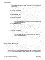
Private User Mobility *....................................................................................................................................38
Logging on to the telephone..................................................................................................................39
Logging off the telephone......................................................................................................................39
Suppressing specific status information..........................................................................................................40
Setting redial list..............................................................................................................................................40
Enabling call list settings................................................................................................................................41
Using Call Center functions............................................................................................................................41
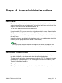
Chapter 4: Local administrative options..............................................................................43
Audit menu......................................................................................................................................................43
Saving and reloading data..............................................................................................................................43
Testing the telephone......................................................................................................................................44
Replacing a defective telephone....................................................................................................................45
Relocating the telephone................................................................................................................................45
Chapter 5: Accessories..........................................................................................................47
Accessories....................................................................................................................................................47
Button module BM32......................................................................................................................................47
About connecting button module BM32..................................................................................................48
Service Adapter..............................................................................................................................................49
Downloading software with the Service Adapter............................................................................................50
Headsets........................................................................................................................................................51
About operating headsets..............................................................................................................................52
1408/1416 Telephones IAM Guide
January 2010
5
Contents
Chapter 6: Technical data......................................................................................................53
Chapter 7: System Components............................................................................................55
Telephones, spare parts, labels, etc...............................................................................................................55
Headsets........................................................................................................................................................59
Chapter 8: Abbreviations........................................................................................................63
Index.........................................................................................................................................65
6
1408/1416 Telephones IAM Guide
January 2010
Chapter 1: Introduction
About this guide
This guide describes how to install and maintain the Avaya 1400 Series telephones product
line connected to Avaya Integral Enterprise telephone systems and troubleshoot telephone
problems.
Intended audience
This document is intended for personnel who install and administer the Avaya 1400 Series
telephones.
Other documentation and customer support
See the Avaya Support Web site: http://support.avaya.com for Avaya 1400 Series telephones
technical and end user documentation.
The following documents are available for the Avaya 1400 Series telephones:
• Avaya 1408 and 1416 connected to Integral Enterprise, user guide
• Avaya 1408 and 1416 connected to Integral Enterprise, walled sheet
For Avaya 1400 Series telephones support, call the Avaya support number provided to you by
your Avaya representative or Avaya reseller. Information about Avaya products can be
obtained at the internet site mentioned above.
Warning:
For Australian installations only:
Installations of the 1416 terminal with an 1151 PSU and DBM32 must be restricted to the
same building as the host Gateway. That is, the 1416 – if installed with an 1151 PSU and
DBM32 – cannot be connected in a campus environment where the 1416 terminal is installed
in a building separate from the building housing the Gateway. This application cannot be
used with exposed (out-of-building) wiring.
1408/1416 Telephones IAM Guide
January 2010
7
Introduction
For installations in which the 1416 is used without the 1151 PSU and DBM32, campus
connections are acceptable: the 1416 can be located in a separate building in these cases.
This restriction applies to Australian installations only.
8
1408/1416 Telephones IAM Guide
January 2010
Chapter 2: Overview
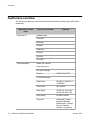
Overview of phone buttons and features
Avaya 1408 Telephone
Avaya 1416 Telephone
1408/1416 Telephones IAM Guide
January 2010
9
Overview
No.
10
Name
Description
1
Call/Message
Waiting Indicator
This light flashes when you receive an incoming call.
Additionally it indicates you have voicemail
messages waiting.
2
Phone Display
There are 3 (1408) or 4 (1416) lines in the phone
display. The phone display presents calling or called
party identification, user options, and other
information relevant to using the phone.
When the phone is idle, the top line shows the
number of missed calls. The top line also shows the
phone number and name you set and the date and
time. The top line shows the phone number and name
you set and the date and time.
The middle line (1408) or two lines (1416) display
status information.
The bottom line displays the softkey labels.
3
Softkeys
Press the softkeys to select the softkey labels. The
softkey labels show you the action that each softkey
produces. The labels and the actions vary depending
on the object that is selected.
4
OK
Press the OK button to open a selected menu item
or confirm an input.
5
Phone/Exit
Press the Phone/Exit button to return back to the idle
display from a menu.
6
Function keys /
Destination keys /
Partner keys
There are 8 (1408) or 16 (1416) keys that can be
programmed as either function keys or destination
keys. Press a labeled function key to enable or
1408/1416 Telephones IAM Guide
January 2010
Overview of phone buttons and features
No.
Name
Description
disable that function. The function keys provide the
same functions that are available in the menu. When
a call number is programmed on the key press the
key to dial the destination. (Partners are special
destinations, see chapter Partners for more
information)
7
Hold
Press the Hold button (R button) to put the active call
on hold or to toggle between an active call and a call
on hold. Press the Hold button (R button) to put the
active call on hold.
8
Conference
Press the Conference button to add another party to
an existing call.
9
Transfer
Press the Transfer button to transfer a call to another
number.
10
Drop
Press the Drop button to drop the active call. While
on a conference call, press the Drop button to drop
the call party which is marked in the display from the
conference call.
11
Headset
Press the Headset button to use the headset if it is
connected. Only HIS headset cords are compatible
with your phone.
12
Volume
Press + or - on the Volume button while active on the
handset, headset or speaker to adjust the volume.
While not on a call, press + or - to access the audio
settings menu.
13
Mute
Press the Mute button to mute a call in progress. To
take a call off mute, press Mute again.
14
Speaker
Press the Speaker button to activate the loudspeaker
or the handsfree equipment.
15
Redial
Press the Redial button to either dial the last number
you dialed or display the redial list from which you can
select a number to redial.
16
Call Log
Press the Call Log button to view a list of your
outgoing, incoming, and missed calls. The icon on the
Call Log button is illuminated when you have missed
calls.
Press the Call Log button to view a list of your missed
calls. The Icon on the Call Log button is illuminated
when you have missed calls.
17
Phone book /
Contacts
Press the Phone book / Contacts button to view the
entries in your phone book or contact list.
1408/1416 Telephones IAM Guide
January 2010
11
Overview
No.
Name
Description
18
Avaya Menu
Press the A button to access the Avaya menu. The
Avaya menu provides options that allow you to
customize phone settings, configure call logging and
select the display language.
19
Message
Press the Message button to connect directly to your
voicemail system.
20
Navigation
Arrows
Press the up and down navigation arrows to scroll
through lists. Press the right and left navigation
arrows to navigate between different views of an
application, to move the cursor during text input, or
to turn an option on or off.
Menu overview
The following table contains an overview of the menu structure of the Avaya 1400 Series
telephones. The first three menu levels are shown. The menu structure shown here may differ
from the actual menu structure on your telephone. Deviations from the menu overview shown
here may arise due to the features used, the accessories in use and the assignment of the
function keys. Remarks and notes are shown in italic font.
Menu item in basic
menu
Call diversion
One menu level lower
One menu level lower
to
to
on busy
Ex. aft. time
Int. after time
Double call
Automatic 1
Automatic 2
Set automatic
to
StartTime 1
StopTime 1
12
1408/1416 Telephones IAM Guide
January 2010
Menu overview
Menu item in basic
menu
One menu level lower
One menu level lower
Weekday 1
to
StartTime 2
StopTime 2
Weekday 2
Appointments
Call diversion key 1
Number:
Call diversion key 2
Number:
Partner diversion
Partner diversion from my
Phone
Partner diversion to my
Phone
Partner diversion from/to
others
Set deputy key
Set/delete Partner
diversion
Partner diversion key 1
Partner diversion key 2
Appointment data (only if
appointment entered)
Enter new appointment
On NDL phones only as
soft key available
Time 00:00
Date XX.XX.XX
Text
Call no.
Appointments
Charges
Charge display for last
call
... for next-to-last call
... for third-last call
... for fourth-last call
Total call charg
1408/1416 Telephones IAM Guide
January 2010
13
Overview
Menu item in basic
menu
One menu level lower
One menu level lower
Charges
Charge displ.
Delete single counter
Lock
Lock telephone
Change PIN
Old PIN
New PIN
Re-enter PIN
Save PIN
Automatic locking
Lock at 00:00
Time zones
Current time zones
Settings
The complete settings
menu is shown in the
following separate table.
Menu settings overview
The following table contains an overview of the settings menu structure of the Avaya 1400
Series telephones. Three menu levels are shown starting with the appropriate settings
submenu.
Menu item in setting
menu
Display/Acoustics
One menu level lower
One menu level lower
Second call
Do not disturb
Ringing tone
Signal tone
VIP ringing tone
Set acoustics
14
1408/1416 Telephones IAM Guide
Handset
January 2010
Menu settings overview
Menu item in setting
menu
One menu level lower
One menu level lower
Loudspeaker
Ringing tone
Alerting tone
Signal tone
Headset volume
Select Ringer melody…
Set contrast
Set brightness
Switch language
Number and variety of
languages depends on
the software image
loaded in the telephone
Set handsfree
Set own call number
Name
Call no.
Display date/time
Request time / partner /
DSS
Recogn. partial nos.
Favorite Screen active
Keys
Set destination keys
Set new destination
Edit destination key
Delete destination key
Set functions keys
All possible functions are
listed
Set macro function (only
1416)
Call diversion 1
Call diversion 2
Call pick-up 1
1408/1416 Telephones IAM Guide
January 2010
15
Overview
Menu item in setting
menu
One menu level lower
One menu level lower
Call pick-up 2
Going
Coming
Display key assignement
Key beep
Dial settings
Anonymous call
DTMF duration
Direct dial
Direct dest. dial
Direct digit dial
Refer-back dest
Applications
Part of group line
Partner
Adapt my partners
Set/delete partner
diversion
Adopt partner group size
CC user function
Answer call
CSTA answer call
Handsfree AB
Handset On/Off
DSS direct call
Set DSS direct call dest
Ed. DSS direct call dest
Del. DSS direct call dest.
Security
Save data
Save data at:
Save data locally
Save data centrally
Save centrally
16
1408/1416 Telephones IAM Guide
January 2010
Menu settings overview
Menu item in setting
menu
One menu level lower
One menu level lower
Set emergency numbers
Emergency destin. SOS
1
…
Emergency destin. SOS
8 (1408) or 10 (1416)
Relocate telephone
Info/Service
Info
HW type, Refer. no,
Bootstrap, Software,
Load date, Protocol,
Serial no.
Tone ringing
sounding
Display
test procedure
Set contrast
Set brightness
Test LED
all LED's are switched on
Keypad
Press key
Speech path
Handset
Monitoring
VIP
Test memory
Result is shown
PIN
Send VIP functions
Recv. VIP
Set VIP partner
Remote Headset
Display call list
1408/1416 Telephones IAM Guide
January 2010
17
Overview
Audit menu overview
The following contains an overview of the audit menu structure of the Avaya 1400 Series
telephones.
Menu item in audit
menu
Telephone ID
One menu level lower
Settings
Hardware type
ComCode
Bootstrap
Software
Load date
Protocol
Serial no.
1st install
Terminal settings
Delete sum counter
Layer 2 perm act.
Dec. point charges
Protocol
TN1R6, VN2, ETSI
CC autocall accept
18
1408/1416 Telephones IAM Guide
Date format
DD,MM.YY, MM.DD.YY,
YY.MM.DD
Time format
24h, am/pm
Date delimit.
XX.XX.XX, XX-XX-XX,
XX/XX/XX, XX XX XX
Time delimit.
HH.MM, HH:MM
Time zone
Amsterdam, Athens,
Bangkok, Brussels,
Buenos Aires, Chicago,
Denver, Frankfurt,
Helsinki , Hong Kong,
January 2010
Audit menu overview
Menu item in audit
menu
One menu level lower
Settings
Copenhagen, London,
Lisbon, Los Angeles,
Madrid, Mexico City,
Moscow, New York, Oslo,
Paris, Peking, Rome,
Singapore, Stockholm,
Sydney, Tokyo
Esc key dial tone
Use MSN
Call sequence GB
PDIV LED flashing
Name from TBook
CSTA MakeCall tone
CDiv. locked phone
Set redial
Auto-redial status
Redial interval
10, 20, 30, 60 seconds
Number
Set call list
Call list
Delete after time
Dwell time (only if “Delete
after time” is activated))
Incoming ELC code
Outgoing ELC code
Internal calls
CBR. internal calls (only if
“Internal calls” is set off)
External calls
Operator calls
Picked-up calls
1408/1416 Telephones IAM Guide
January 2010
19
Overview
Menu item in audit
menu
One menu level lower
Settings
User menu
Set handsfree
Outg. sensitiv
Inc. sensit
Reverberation ti
Echo comp. level
Echo comp. time
Attenuation le
Handsfree Parameter Set
Test patt.
Per. signal
Single pulse
No signal
Close Test Loop
Error Counter
Frame losses
Frame errors
Error messages
Delete error counter
External line code
Code 1 Lock
Code 2 Lock
Code 3 Lock
Code 4 PIN check
PIN check duration
Code 5 PIN check
PIN check duration
Delete all entries
Total memory
Phone book
Function keys
20
1408/1416 Telephones IAM Guide
January 2010
Audit menu overview
Menu item in audit
menu
One menu level lower
Settings
Lock no. memory
Features
Software reset
Set features
MSN0: ... MSN9
MTB DAD
MTB SUB
Start search
DAD save
Save subad
Barred features' list
Appointments
Announce ackn.
Auto call div.
Callback
Callback request
Call trap
Charges
CC Emergency
CC function
CSTA ans. call
Cut-in
Disp. ptr. call
DSS direct Call
Do not disturb
Executive key
Ext. part. div
Handsfree AB
1408/1416 Telephones IAM Guide
January 2010
21
Overview
Menu item in audit
menu
One menu level lower
Settings
Hold/Retrieve
Hunt group
Ind. emerg. call
Local phone book
Main phone book
Priv. User Mob.
Redial abroad
Relocation
Restrict sign.
Set Acoustics
Set Dble Call
Set VIP
Set call FWD
Set call div.
Set func. keys
Set language
Set partners
Set phone
Test mode
Time zones
Trap call
Show telephone status
Call diversion
Intern after time
Ex.aft.time
22
1408/1416 Telephones IAM Guide
January 2010
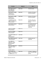
Barred features' list
Barred features' list
The barred features' list enables you to bar (disable) and release (enable) features on each
telephone.
The following matrix indicates the respective features, which settings are possible, the
predefined factory setting and additional information.
Note:
A barred feature cannot be assigned to a function key. It is deleted, when the setting of the
appropriate feature is changed from free to barred.
Menu item
Feature
Available settings
Factory
setting
and
notes
Auto call
div.
Automatic call
diversion
Free: The menu items “Automatic 1“
and “Automatic 2“ are shown in the
call diversion menu. The automatic
call diversion can be set.
Barred: This menu item is not
offered to the user.
Barred
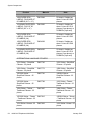
Appointmen
ts
Appointments
Free: The user can use this
function.
Barred: This menu item is not
offered to the user.
A specified appointment will not be
processed.
Free
Announce
ackn.
VIP function
announcement
with
acknowledgeme
nt
Free: VIP calls with the attribute
”announcement with
acknowledgement" will be carried
out.
Barred: For VIP calls with the
attribute “announcement with
acknowledgement” only the
loudspeaker is switched on
(announcement).
Barred
Callback
request
Callback
request
Free: The user can use this
function.
Callback request allows the user to
enter an explicit callback request in
the subscriber's call list when their
phone is free or busy.
Barred
1408/1416 Telephones IAM Guide
January 2010
23
Overview
Menu item
Feature
Available settings
Factory
setting
and
notes
Barred: This menu item is not
offered to the user.
24
Callback
Automatic
callback if busy
Free: The user can use this
function.
Barred: This menu item is not
offered to the user.
A callback that has already been
programmed will be carried out.
Free
Call trap
Call tracing
Free: During a call, the user is able
to store the call number of the
opposite subscriber in the system.
Barred: This menu item is not
offered to the user.
Barred
Charges
Call charges
Free: The user can use this
function.
Barred: This menu item is not
offered to the user.
The charges counter will not be
affected. Call charges are shown
during a conversation.
Free
Do not
disturb
Do not disturb
Free: The user can switch certain
ring tones on and off.
Barred: This menu item is not
offered to the user.
Free
CC
Emergency
CC Emergency
Free: Function keys SupAct and
SupPas are predefined.
Barred: This menu item is not
offered to the user.
Barred
CC function
Automatic call
distribution, CC
Free: The user is able to log in to
automatic call distribution (CC).
Barred: This menu item is not
offered to the user.
Barred
Cut-in
Cut-in
Free: The user can use this
function.
Barred: This menu item is not
offered to the user.
Barred
Disp. ptr.
call
Display partner
call
Free: Every call reaching one of
your partners is shown in your
display.
Barred: No call reaching your
partners is shown in your display.
1408/1416 Telephones IAM Guide
January 2010
Barred features' list
Menu item
Feature
Available settings
Factory
setting
and
notes
DSS direct
call
DSS direct call
destinations
Free: The user can programme
DSS direct call destination keys on
button modules.
Barred: This menu item is not
offered to the user.
Barred
Ext. part. div
Extended
partner
diversion
Free: Subscribers of a partner
group can set up a call diversion to
any number for every subscriber in
the partner group (e.g. a partner's
mobile or home number).
Barred: This menu item is not
offered to the user.
Barred
Executive
key
Executive
secretary line
Free: An executive secretary line
(abbreviated to executive line) can
be set up. Each partner within a
partner group is able to seize a line
if the executive line key is set up on
his telephone.
Barred: This menu item is not
offered to the user.
Barred
Handsfree
AB
Handsfree
answer back
Free: The user is able to set up his
telephone so that calls are accepted
automatically.
Barred: This menu item is not
offered to the user.
Barred
Hold/
Retrieve
CSTA hold and
retrieve call
Free: For multiple connections, only
the shift key is used for control, and
not the refer back and/or shift keys.
Barred: The phone is not capable of
processing and producing “hold and
retrieve call” messages.
Barred
Hunt group
Hunt group
Free: The user is able to participate
in a hunt group.
Barred: This menu item is not
offered to the user.
Barred
Ind. emerg.
call
Individual
emergency call
Free: The user can store 8 (1408) or
10 (1416) numbers as individual
emergency call numbers and
assign them to function keys.
Additionally he can dial these
numbers at any time.
Barred: This menu item is not
offered to the user.
Free
1408/1416 Telephones IAM Guide
January 2010
25
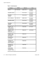
Overview
Menu item
Feature
Available settings
Factory
setting
and
notes
Set: The user cannot change an
individual emergency number. Also
he cannot store any new
emergency numbers. However, he
can dial an individual emergency
call number at any time.
26
Local phone
book
Local phone
book
Free: The user can use this
function.
Barred: The user cannot make any
settings to the local phone book.
The menu options ”Edit" and
”Delete" are not offered to the user
in the phone book menu or when he
presses a destination key.
Free
Main phone
book
Main phone
book
Free: The user can use this
function.
Barred: This menu item is not
offered to the user.
Barred
Priv. User
Mob.
Mobile call
number
Free: The user is able to register
(log in) at another telephone in the
system and use it as if it were his
own.
Barred: This menu item is not
offered to the user.
Programmed function keys with the
”Log in" and ”Log out" functions will
be deleted.
Barred
Restrict
sign.
Restrict partner
signaling
Free: The user is able to restrict the
partner signal control.
Barred: This menu item is not
offered to the user.
Barred
Redial
abroad
Enables delayed
automatic redial
abroad
Free: The user is able to use the
delayed redialing function when
dialling into certain analogue
exchanges. The delayed redialing
abroad variant works by lifting the
handset and not via signalling from
the system.
Barred: Under certain
circumstances, the user will not be
able to use the delayed redialling
abroad variant.
Barred
1408/1416 Telephones IAM Guide
January 2010
Barred features' list
Menu item
Feature
Available settings
Factory
setting
and
notes
Relocation
Relocate ISDN
telephone
Free: The user can use this
function.
Barred: This menu item is not
offered to the user.
Free
Set
Acoustics
Set acoustics
and contrast
Free: The user is able to change the
acoustics and contrast settings in
the main menu or during a call.
partially: The user can only change
the volume of the handset and that
of the loudspeaker in handsfree
mode during a call. The settings are
permanently saved. A function key
that has been programmed for the
”Set contrast" function will be
deleted.
Barred: This menu item is not
offered to the user.
Free
Set call div.
Call diversion
setting
Free: The user can use this
function.
Barred: The user can only switch on
or off a call diversion that had
previously been created. Neither
sources nor destinations can be
specified.
Free
Set Dble
Call
Double call
Free: The user can use this
function.
Barred: The user can only switch
prescribed Double Call destinations
on or off. Neither sources nor
destinations can be specified.
Free
Set func.
keys
Set function
keys
Free: The user can use this
function.
Barred: This menu item is not
offered to the user.
Free
Set call
FWD
Call transfer
internal and
external
Free: The menu item Call
forwarding is shown in the Call
diversion menu.
Barred: The user can only switch on
or off Call forwarding that had
previously been created. Neither
sources nor destinations can be
specified.
Free
1408/1416 Telephones IAM Guide
January 2010
27
Overview
Menu item
Feature
Factory
setting
and
notes
Set
language
Set language
Free: The user can use this
function.
Barred: This menu item is not
offered to the user.
Free
Set partners
Partner
Free: The user can use this
function.
Barred: This menu item is not
offered to the user.
Free
Set phone
Set telephone
Free: The user can use this
function.
Barred: The Setting menu is not
offered to the user.
Free
Set VIP
VIP functions
receive
VIP functions
send
if necessary VIP
partner
determine
Free: The user can use this
function.
Barred: This menu item is not
offered to the user.
Barred
Free: The user is able to test various
telephone functions.
Barred: This menu item is not
offered to the user.
Free
Free: The user can use this
function.
Barred: This menu item is not
offered to the user.
Free
Test mode
Time zones
28
Available settings
Time zones
1408/1416 Telephones IAM Guide
January 2010
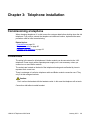
Chapter 3: Telephone installation
Commissioning a telephone
When changing telephones, it is vital to save the customer data before shutting down the old
telephone. If you wish to connect the telephone at a different location, implement the same
procedure used for initial commissioning.
Related topics:
Connections on page 29
Telephone sockets on page 30
Plugging in the telephone on page 33
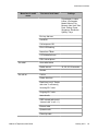
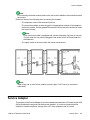
Connections
The wiring is the same for all telephones. A button module can be connected to the 1416
telephone. Power supply with a separate power supply unit is not necessary unless you
connect one or more button module.
The sockets are located on the back of the telephone housing and are flanked by icons to
represent their correct use.
There is no danger of confusion telephone cable and Button module connection cord. They
only fit in their assigned sockets.
Caution:
Don't confuse the handset with the headset socket. In this case the telephone will not work.
Connection with/without corded headset:
1408/1416 Telephones IAM Guide
January 2010
29
Telephone installation
Connection with/without corded headset and DBM32 Button module:
Telephone sockets
In the following table you can find the connections of all wiring pins of the 4– and 8–pole
telephone sockets.
30
1408/1416 Telephones IAM Guide
January 2010
Commissioning a telephone
UPN socket 1416
1 – NC
2 – NC
3 – NC
4 – UPN-LIA
5 – UPN-LIB
6 – NC
7 – -48V
8 – +48V
UPN socket 1408
1 – NC
2 – NC
3 – NC
4 – UPN-LIA
5 – UPN-LIB
6 – NC
7 – NC
8 – NC
MOD socket 1408/1416
1 – TXD
2 – RXD
3 – RQ
1408/1416 Telephones IAM Guide
January 2010
31
Telephone installation
4 – GT
5 – GND
6 – RST/SYNC
7 – -48V
8 – +48V
MOD socket DBM32
1 – TXD
2 – RXD
3 – RQ
4 – GT
5 – GND
6 – RST/SYNC
7 – -48V
8 – +48V
Handset socket 1408/1416
1 – MIC
2 – GND
3 – SPK
4 – +V
Headset socket 1408/1416
1 – MIC
2 – GND
3 – SPK
4 – +V
32
1408/1416 Telephones IAM Guide
January 2010
Commissioning a telephone
Plugging in the telephone
After plugging in the telephone or at each reset, the bootstrap compares the check sum of the
software to the default value. It ensures, that software can be loaded, only if it compatible with
the terminal.
The phone also ensures that initial factory data was written during the factory procedures. If
the phone has no factory data (or it is damaged) and no factory SW can be started all available
LEDs will be activated to indicate the error. If the phone has no factory data (or it is damaged)
and factory SW starts automatically – The screen stays blank to indicate the error.
Plug in the telephone.
The bootstrap performs a check sum test.
• If successful, the software version is indicated in the display, e.g.
T015_ODE.xx1.
• otherwise, the bootstrap returns the message NO SOFTWARE LOADED
Note:
In this case, the software can be downloaded from the telephone system or
via the TCM tool.
Next steps
Set Time / Partner / DSS in the Avaya Menu > Settings > Display/Acoustics> Time/Partner/
DSS. As a result the time and set up partner group are shown on the display. The telephone
ID is thus initialized. The connection to the system is also be checked at this point.
Note:
As also the CM application SW is in parallel in the phone, it might be that the phone starts
erroneously with the CM application SW depending if the phone was plugged to a CM before.
To switch back to the I55 application SW, unplug the phone and replug while holding the Amenu button and the Drop button pressed simultaneously. To switch manually to CM
application SW, unplug the phone and replug while holding the A-menu button and the
Transfer button pressed simultaneously.
1408/1416 Telephones IAM Guide
January 2010
33
Telephone installation
Setting date and time format
1. Open the audit menu.
2. Select Terminal settings.
3. Press the OK button.
4. Select Date format.
5. Press the Change softkey to select one of the following:
• DD.MM.YY
• MM.DD.YY
• YY.MM.DD
6. Select Time format.
7. Press the Change softkey to select one of the following:
• 24h
• am/pm
8. Select Date delimit..
9. Press the Change softkey to select one of the following:
• XX.XX.XX
• XX-XX-XX
• XX/XX/XX
• XX XX XX
10. Select Time delimit..
11. Press the Change softkey to select one of the following:
• HH.MM
• HH:MM
12. Press the Done softkey.
Setting up external line codes
External calls are impossible, if the telephone is locked with a local PIN.
34
1408/1416 Telephones IAM Guide
January 2010
Setting up a PIN for outgoing external calls
You can enter three three-digit external line codes in the audit menu. This codes are checked if
the telephone is locked with a local PIN. Depending on this check a call is either executed or
rejected.
Note:
If the PIN is set in the system, these settings determine the length and evaluate the selection
code for external calls.
1. Open the audit menu.
2. Select External line codes.
3. Press the OK button.
4. Select one of the following:
• Code 1 lock
• Code 2 lock
• Code 3 lock
5. Enter one to three digits of the external line code.
6. Press the Done softkey.
Setting up a PIN for outgoing external calls
Making an external call, the subscriber can dial an additional PIN or project number, which is
transferred to the central call charge data recording.
1. Open the audit menu.
2. Select External line codes.
3. Press the OK button.
4. Select Code 4 PIN check.
5. Enter a maximum 5 digit ELC (= external line code) for outgoing external calls and
then the PIN or project number. This ELC is set up for general or individual PIN
checks in the telephone system. To enable call charge data recording to recognize
the PIN, the ELC for dialling with PIN must be different from the ELC for dialling
without PIN. This must be set up in the telephone system accordingly.
6. Select PIN check duration.
1408/1416 Telephones IAM Guide
January 2010
35
Telephone installation
7. Enter the length of the PIN that is set up in the telephone system. This PIN has a
maximum 12 digits and applies throughout the system. Corresponding to the
entered length, the digits entered after the ELC are presented with PIN code (as ”*").
8. Press the Done softkey.
Setting loudspeaker volume
1. Press the Avaya Menu button.
2. Select Settings.
3. Press the OK button.
4. Select Display/Acoustics.
5. Press the OK button.
6. Select Set acoustics.
7. Press the OK button.
8. Select Loudspeaker.
9. Press the left/right arrow button or enter numeric characters to change the setting.
The volume of the loudspeaker should be kept as low as possible. Handsfree
operation works best under these conditions.
10. Press the Save softkey.
Setting handsfree parameter
In the settings menu (Avaya Menu > Settings > Display/Acoustics > Set handsfree)
handsfree operation can be set to normal, echo or muffled surrounding conditions. Each
of these three settings corresponds with a parameter set. All parameter sets can be modified in
the audit menu.
Note:
It is also possible to call up this menu during a handsfree connection and subsequently
change the settings. This is a good means of directly testing the settings. When testing in
this manner, speak to an opposite subscriber who is using the handset.
36
1408/1416 Telephones IAM Guide
January 2010
Setting handsfree parameter
When setting the parameters, consider the room conditions, the surrounding noises, and the
type of telephone conversations (internal, local, long-distance, overseas, …) most frequently
made by the respective user.
1. Open the audit menu.
2. Select Set handsfree.
3. Press the OK button.
4. Select Handsfr. par. set.
Note:
Select the desired parameter set first, because all other settings in this menu
apply to the specified parameter set. Individual settings can be saved for each
parameter set.
5. Select the desired parameter set.
6. Select Outg. sensitivity.
This menu item is used to influence the response threshold for outgoing calls.
7. Select one of the following:
• Move setting to the left: higher sensitivity (low voice, quiet room)
• Move setting to the right: lower sensitivity (loud voice, noisy room)
8. Select Inc. sensitivity.
This menu item is used to influence the response threshold for incoming calls.
9. Select one of the following:
• Move setting to the left: increased sensitivity (quiet call partner, high
attenuation on the line)
• Move setting to the right: reduced sensitivity (loud call partner, little
attenuation on the line)
10. Select Reverberate ti.
This menu item is used to compensate for reverberation time in the room where the
telephone is located (to adapt handsfree operation to the room conditions.
11. Select one of the following:
• Move setting to the left: the room has a short reverberation time (quiet
room)
• Move setting to the right: the room has a long reverberation time (echoing
room)
12. Select Echo comp. level.
This and the following setting affect the ”Reverberation time of the connecting line".
Because most cases are adequately covered by the default settings, you only rarely
need to change these settings. You can best determine the echo characteristic when
1408/1416 Telephones IAM Guide
January 2010
37
Telephone installation
using the handset for connection, and take these results as the basis for setting the
handsfree mode.
Echo comp. level is used to compensate the signal level that is reflected from the
connecting line and the opposite subscriber.
13. Select one of the following:
• Move setting to the left: if no echo or only a faint echo can be heard
• Move setting to the right: if a loud echo can be heard
14. Select Echo comp. time.
This menu item is used to compensate the effective time of the echo on the line.
15. Select one of the following:
• Move setting to the left: if only a short time delay is apparent between the
actual speech and the resulting echo
• Move setting to the right: if a long time delay is apparent between the actual
speech and the resulting echo
16. Select Attenuation level.
Handsfree operation works in accordance with the principle of the ”attenuation
scales". This means that one signal direction only (e.g. outgoing) can be active
(switched through) at any one time. During this period, the opposite side (e.g.
incoming) is ”attenuated" with a configurable value. This menu item is used to set
the attenuation level of the handsfree electronics in the telephone.
17. Select one of the following:
• Move setting to the left: increased two-way communication, but also more
echo for the other party to the call
• Move setting to the right: reduced two-way communication, but also less
echo for the other party to the call
Better duplex communication will mean more echo for the opposite subscriber. The
echo behavior can only be heard and thus evaluated by the other party of the call.
Private User Mobility *
The Private User Mobility feature allows you to log on to any telephone inside the telephone
system and have access to your personal settings (call list, redial, call diversion, and callbacks).
Callers will reach you on this telephone when they dial your call number. Charging units
incurred are allocated to your call number.
To use the PUM function, it must be enabled in the telephone system. Furthermore two function
keys must have the functions Log on and Log off assigned to them (look at the UsersGuide).
38
1408/1416 Telephones IAM Guide
January 2010
Private User Mobility *
This function is protected by the same PIN as the locking function. To use PUM, this PIN have
exact six digits.
Related topics:
Logging on to the telephone on page 39
Logging off the telephone on page 39
Logging on to the telephone
1. Press the Log in user function key.
2. Enter your personal call number.
3. Select Password:.
4. Enter your PIN.
The PIN is displayed by asterisks *.
5. Select Log in user.
6. Press the OK button.
A status message appears in the display. You are now logged in to this telephone
and you can use it exactly like your own set.
Logging off the telephone
Press the Log out user function key.
Your personal settings (call list, redial, call diversion, callbacks entered) are cleared.
Note:
You are logged off automatically if another subscriber logs on to this telephone.
1408/1416 Telephones IAM Guide
January 2010
39
Telephone installation
Suppressing specific status information
Usually the status information shows activated call diversions in the display. Some of these
status messages can be suppressed partly or totally.
1. Open the audit menu.
2. Select Show telephone status.
3. Press the OK button.
4. Select one of the following:
• Call diversion if you want to suppress the call number of the call diversion
destination in the status message.
• Intern after time if you want to suppress the complete status message in
case a call diversion “internal after time” is activated.
• Ex.aft.time if you want to suppress the complete status message in case
a call diversion “external after time” is activated.
5. Press the Done softkey.
Setting redial list
The redial list can contain up to 30 entries. Up to ten of these are reserved for the most recently
dialed numbers. The remaining entries are generated by callback request. Each callback
request that you initiate is its own entry in the redial list.
The number of entries for the most recently dialed numbers can be decreased.
1. Open the audit menu.
2. Select Set redial.
3. Press the OK button.
4. Select Number.
The number of redial list entries reserved for the most recent dialed numbers is
shown.
5. Enter a value between 1 and 10.
6. Press the Done softkey.
40
1408/1416 Telephones IAM Guide
January 2010
Enabling call list settings
Enabling call list settings
You can grant a user to change call list entries to some extent. For example, remove internal
calls from the call list. Then an entry is included in the call list only when the internal caller
explicitly requests a callback.
1. Open the audit menu.
2. Select Set call list.
3. Press the OK button.
4. Select Call list (off).
5. Press the Change softkey.
6. Press the Done softkey.
Now the user can set by oneself, which kind of calls will be stored in the call list (Avaya Menu >
Settings > Display call list).
Using Call Center functions
Before Call Center functions can be used with Avaya 1400 Series telephones some
requirements must be fulfilled.
Some settings have to be activated in audit menu.
In the Barred features' list:
• CC functions: mandatory
• CSTA answer call: The telephone can accept a CSTA Answer Call with the Speaker
button or with a headset.
• CC emergency : To enable a help notification to the supervisor during an ongoing
call. The supervisor can then listen to the call.
In Terminal settings:
CC autocall accept: If CC calls should be accepted automatically
For a faster logging in, it is recommended to set up a CC function key.
1408/1416 Telephones IAM Guide
January 2010
41
Telephone installation
42
1408/1416 Telephones IAM Guide
January 2010
Chapter 4: Local administrative options
Audit menu
The default settings and authorizations for the user can be changed in the audit menu and
various test procedures can be implemented. The individual menu items can be found in the
chapters Audit menu overview and Barred features' list .
You will need an auditor PIN to enter the Audit menu.
Using this auditor PIN, you can even unlock a telephone locked by a user. After entering the
PIN, you must wait for the timer to count down. The telephone is then unlocked.
If the telephone was locked before, you should make sure that you lock it again after leaving
the audit menu.
In case the telephone was locked by the telephone system, you need the system terminal to
unlock it (See the appropriate service manual for more details).
Note:
Three unsuccessful attempts to unlock the telephone will result in the telephone being
blocked for 15 minutes. You can, however, unlock it at any time using the auditor password.
Saving and reloading data
You must save the phone book and the customer data prior to a change of the telephone or
to a basic initialization, and subsequently reload the data into the telephone.
The data transfer can be done via your system or locally via a PC. The first way is not matter
of this manual. If you are using a PC, the TCM program must have been installed (TCM =
Terminal Configuration Manager).
Prerequisites
The telephone is in idle state for upload or download, that is the following requirements are met:
1408/1416 Telephones IAM Guide
January 2010
43
Local administrative options
• The telephone is idle in terms of the switching technology.
• All procedures are finished.
• The telephone is unlocked, and the idle display is active.
Note:
During the data transfer all events are barred on the telephone.
If the telephone detects a fault, this will be indicated to the PC. The affected data will be reinitialized.
1. Connect the PC and the telephone via the Service Adapter:
a. Plug the provided cable into the MOD jack of the telephone.
b. Plug the USB cable into an appropriate interface of the PC.
2. Activate the data transfer in the TCM program.
Example
A detailed example how to perform a software download can be found in the chapter
Accessories > Downloading software with the Service Adapter.
Testing the telephone
You can test various functions. As long as a telephone is in test mode, it cannot receive any
calls. Each discrete test only lasts a few seconds.
1. Press the Avaya Menu button.
2. Select Settings.
3. Press the OK button.
4. Select Info/Service.
5. Press the OK button.
6. Select one of the following:
• Tone ringing ...
• Display ...
• Set contrast ...
• Set brightness ...
44
1408/1416 Telephones IAM Guide
January 2010
Replacing a defective telephone
• Test LED ...
• Keypad ...
• Speech path ...
• Test memory ...
7. Press the OK button.
The test is executed and the result is shown.
Replacing a defective telephone
On a defective telephone set analyze which of the following cases happened:
• If a hardware part like the display, the keypad or another device is defective, save the
customer data and replace the telephone.
• If the complete hardware is defective, replace the telephone.
• If the software is defective, reload the software.
After having replaced the telephone, do the following:
1. Make sure that the previously installed software is used again.
2. Clear down all memories (Audit menu item Delete all entries).
3. Reload the old customer and phone book data, if they are available.
Relocating the telephone
1. Press the Avaya Menu button.
2. Select Settings.
3. Press the OK button.
4. Select Security.
5. Press the OK button.
6. Select Relocate.
7. Press the OK button.
1408/1416 Telephones IAM Guide
January 2010
45
Local administrative options
The data is saved locally in the telephone. The status message Relocation
prepared appears.
8. Plug the telephone in at the new location.
The status message Relocation initiated appears on the idle telephone display.
When the relocation is finished, Telephone relocated appears.
9. To cancel the relocation, select Security > Relocate > OK.
46
1408/1416 Telephones IAM Guide
January 2010
Chapter 5: Accessories
Accessories
Accessories
Information
Settings on Avaya 1400
Series telephones
Analogue additional devices
Second handset
to handset interface
Set volume Settings >
Display / Acoustics >
Setting acoustics >
Handset volume 1…8
Headset
to handset interface or to
headset socket
Set volume Settings >
Display / Acoustics >
Setting acoustics >
Headset volume 1…8
Additional digital devices
Button module BM32
to button module socket
Applications for service PC
TCM download
via Service Adapter to
MOD socket.
Download program can
be obtained from the
product service. The
interface settings must
where necessary be
configured for download.
In the TCM: Functions >
Interface > T3 Telephone
(V.24): COM 4; marked
check box T3; 38,400
Baud, data bit, 1 stop bit,
parity odd
Button module BM32
1408/1416 Telephones IAM Guide
January 2010
47
Accessories
You can connect one or two external button modules DBM32 to the 1416 telephone. (Make
sure to use 700.469.968 BUTTON MOD FOR 1400/1500 SERIES, don't mix it up with the other
model for the 1600 IP phones.)
No button module can be connected to the Avaya 1408 telephone.
Depending on the system, the keys can be operated as partner keys, destination keys or
function keys. Destination keys can be stored as DSS direct call destinations or DSS
destinations:
• DSS destinations: Call numbers on button module destination keys
• DSS direct dial destinations: Call numbers on button module destination keys, busy
display, overriding knocking prevention. You must enable the button module in the
telephone’s audit menu. The button module has to be activated under settings in the
telephone menu.
The following graphics show the top and bottom view of DBM32. In the bottom view the
connection cable to the telephone is added.
Note:
When using any button module a power supply 1151C has to be connected additionally.
Related topics:
About connecting button module BM32 on page 48
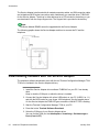
About connecting button module BM32
You can connect one or two external button modules BM32 to the telephone 1416. The
following graphic shows how to connect the button modules BM32.
48
1408/1416 Telephones IAM Guide
January 2010
Service Adapter
Note:
For connecting the button module please refer also to the installation manual delivered with
the module.
Please be aware of the following when connecting the modules:
• The telephone must be disconnected from line.
• The connection cables must be plugged in the appropriate sockets of the telephone
and button module. See the graphic below and the icons next to the sockets to locate
the correct sockets.
Note:
Every connection cable is equipped with a ferrite attenuation ring next to one jack.
The jack near this ring must be plugged in the socket, which is located nearer to
the telephone.
• The upper socket of the last module will remain unconnected.
Note:
When using one or more button module a power supply 1151C has to be connected
additionally.
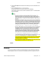
Service Adapter
The purpose of the Service Adapter is to convert datastreams between a PC and a Avaya 1400
Series telephone the way that both devices can handle it. It is used to upload telephone
software or transfer telephone settings from a PC to the telephone and vice versa.
1408/1416 Telephones IAM Guide
January 2010
49
Accessories
The Service Adapter is delivered with all needed connection cables: an USB connection cable
and a telephone MOD socket connection cable. Additionally you need the driver TUBS3410
for the Service Adapter. The driver is either delivered on a CD included in the delivery or you
can download it from the Avaya Support site. The Support link is provided in the delivery.
Note:
The Button Module DBM32 cannot be upgraded with the Service Adapter.
The following graphic shows the Service Adapter and how to connect the PC and the
telephone.
Downloading software with the Service Adapter
The telephone software download is done with the tool Terminal Configuration Manager TCM.
TCM is not included in the Service Adapter delivery.
1. Install the Service Adapter driver software TUBS3410 on your PC if not already
done.
Keep in mind the COM port on which the driver is installed.
2. Connect the Service Adapter with a free USB socket on your PC (USB 2.0 or 1.1)
and with the MOD socket on your Avaya 1400 telephone. See the graphic above.
On the Service Adapter the PWR LED goes on and the LINK/ACT LED is flashing.
3. Start the Terminal Configuration Manager TCM on your PC.
4. Press the button Terminal Software Download.
5. Select the COM port of your Service Adapter driver.
You can find the COM port via Arbeitsplatz > Verwaltung > Gerätemanager >
Ports (Com & LPT).
50
1408/1416 Telephones IAM Guide
January 2010
Headsets
6. Press the File open button and select the software you want to download on the
telephone.
7. Press the Download button to start downloading.
During the data transfer all events are barred on the telephone.
If the telephone detects a fault, this will be indicated to the PC. The affected data
will be re-initialized.
Note:
• Also the boot loader can be downloaded with this procedure. It is
absolutely important to ensure safe power supply of the phone during
boot loader update. Power interrupting during boot loader update
destroys the phone. The phone can only be repaired in repair station in
this case.
• Additionally, the telephones can be set manually into the local application
FW update mode state for TCM with restarting/replugging the phone and
pressing the A-menu key and softkey 2 simultaneously. Upon pressing
the special keys the normal booting process is aborted and the phone
waits in the TCM bootloader mode for a connection. Following display
message shows that the phone is in the TCM local update mode:
INSTALLATION TEST U <VERSION> READY FOR DOWNLOAD
• Also the 1400 telephones can be set manually into the local application
FW update mode state for DCP Serial Download tool with restarting/
replugging the phone and pressing the A-menu key and softkey 1
simultaneously. Upon pressing the special keys the normal booting
process is aborted and the phone waits in the DCP Serial Download
bootloader mode for a connection. Following display message shows
that the phone is in the DCP Serial Download local update mode:
NO APPLICATION FIRMWARE WAITING FOR FW DOWNLOAD
In the DCP Download mode no I55 SW can be downloaded, this is only
for the DCP SW and special DCP compatible bootloader files.
• The 14xx Series Terminals will be connected exclusively to DCP or ISDN
circuitry that has been qualified as a Limited Power Source (LPS), in
accordance with IEC / UL 60950-1.
• For the 14xx Service Adapter: Use only with I. T. E. Listed products and
Avaya digital phone (model 1403, 1408, and 1416).
Headsets
You can connect different cordless and corded headsets to Avaya 1400 Series telephones.
Corded telephones have to be connected to the headset socket of the telephone via a HIC
1408/1416 Telephones IAM Guide
January 2010
51
Accessories
adapter cable. Cordless headsets are connected to the headset socket via a special
"Hookswitch Control Cord" adapter cable. This are included in the delivery.
The chapter system components will show you all headsets that can be used with Avaya 1400
Series telephones.
For using the headsets see the headset's and telephone's user guides.
About operating headsets
• A cordless headset is connected to the headset socket of the Avaya 1400 Series
telephones via a special "D+M" adapter cable. This adapter must be connected
directly to the telephone. Do not connect it to the base station because of strong
whistling noises caused by acoustic feedbacks. The “HIS” adapter cable for corded
headsets or the "9600 Hookswitch Control Cord" adapter cable cannot be used.
Note:
Cordless headsets with a connection via the AEI interface cannot be connected to
Avaya 1400 Series telephones.
• Do not change the default Off setting in Menu > Settings > Remote headset. On
causes undesirable audible DTMF-signals. This setting (On) will only be needed for
new Savy Office (Hydra) headsets.
• The acoustic ring signal on the telephone is transferred to the cordless headset via a
separate call detector cable with its own (separate) microphone. This separate
microphone must first be attached to the grid of the telephone speaker. For mounting
see the headset's user's guide.
• Avaya 1400 Series telephones cannot control a cordless headset without DTMFsignaling, i. e. the cordless headset cannot be switched to online or offline mode with
the HEADSET key on the telephone.
Note:
You can also use the HEADSET key to seize the line or end a call. In order to place a
call correctly using the cordless headset, the headset must always be in headset
mode (online). When doing so, however, you must never press the talk button on
the headset itself.
• The call signal on the telephone must not be set to Off. Otherwise, the call will not be
signaled on the headset.
• Second calls are not signaled on the headset.
• If you are placing a call with the headset, and the other party terminates the
connection, you must also press the call button on the headset so that your telephone
will also be disconnected from the line.
52
1408/1416 Telephones IAM Guide
January 2010
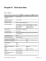
Chapter 6: Technical data
Table 1: 1408/1416
1408
1416
Temperature range for
operation
+4 °C to +49 °C
Temperature range for
storage / transport
-20 °C to +60 °C
Operating voltage
35 to 57 V polarity–dependent
Power consumption
Idle (backlight off): 250 mW
Idle (backlight on): 400 mW
Average: 525 mW
Max: 950 mW
Power supply
Power supply via ISDN cable
Connecting cable
2 wired, 14 ft
Connection system
Terminated with Western Electric plug connector at each end
RJ 45, screened
D–channel protocol
TN1R6
Audio frequency range
300 Hz to 3400 Hz
Interfaces for Button Module
0
1
Interface for local download
1
1
Line interfaces
UPN
Range
1000 m
Weight (incl. handset and
stand)
890 g
1016 g
Width
7.87 in (200 mm)
9.02 in (229 mm)
Length
9.09 in (231 mm)
Height: upright position
flat position
7.80 in (198 mm)
4.17 in (106 mm)
1408/1416 Telephones IAM Guide
Idle (backlight off): 250 mW
Idle (backlight on): 400 mW
Average: 550 mW
Max: 1000 mW
January 2010
53
Technical data
Table 2: Button Module DBM32 (only for 1416)
Temperature range for operation
+4 °C to +49 °C
Temperature range for storage / transport
-20 °C to +60 °C
Operating voltage
35 to 57 V polarity–dependent
Power consumption
Idle: 250 mW
Max: 700 mW
Power supply
Power supply via 1151C connected to 1416
Button Module socket (MOD)
Connection system
MOD: 8 pole Western Electric plug connector
Digital interface
MOD: In/Out
Connection cable
MOD: 8 wired
Width (without bridge to telephone)
3,94 in (100 mm)
Length
9.09 in (231 mm)
Height: upright position
flat position
7.80 in (198 mm)
4.17 in (106 mm)
Weight (incl. stand)
366 g
54
1408/1416 Telephones IAM Guide
January 2010
Chapter 7: System Components
Telephones, spare parts, labels, etc.
Product
Material
Note
PHONES & MODULES
1408 TELSET FOR CM/
IE UpN
700469851
Includes cord.
1416 TELSET FOR CM/
IE UpN
700469869
Includes cord.
BUTTON MOD FOR
1400/1500 SERIES
700469968
Button Module for 32
additional buttons to add
to the phone
SERVICE ADPTR FOR
1400/1500 SERIES
700469976
Adapter for
Administrators only in
case of local SW
download
1600 Amplified Speech
Handset- RoHS
700446388
Amplified Handset for
1600 Series Phones
14xx LINE CORD, 14FT,
2 WIRE, 8 POSITION
JACK
700478399
For desktop usage of
1400 series phones if
cord does not exist at
desktop already
CAT5 ETHERNET CORD
(1FT)
700436710
For 1603 wall-mounting
applications. For 1608 &
1616, cord included in
wall-mount kits
Add-Ons
INSTALLATION ADD-Ons
1408/1416 Telephones IAM Guide
January 2010
55
System Components
Product
Material
Note
1608 WALL MOUNT KIT
700415623
Includes 1 ft Ethernet
cord (no function for
1400) and screws
1616 WALL MOUNT KIT
700415631
Includes 1 ft Ethernet
cord (no function for
1400) and screws
Power Options for 1400 TDM/digital PHONES with button modules
1151C1 Power Supply
700356447
1151C1 & 1151C2
products will include
CAT5 cable for IP
Phones.
1151C2 Power Supply
(with battery backup)
700356454
1151C1 & 1151C2
products will include
CAT5 cable for IP Phones
US Plug (15A, 120V)
17505
405362641
All power cords must be
ordered separately!
Europe Plug (10A)
12013S
407786623
All power cords must be
ordered separately!
UK Plug (10A) 14012
407786599
All power cords must be
ordered separately!
Australia/NZ (10A) Plug
15012
407786631
All power cords must be
ordered separately!
India Plug (10A) SPCP250CIM
407790591
All power cords must be
ordered separately!
Argentina Plug
408161453
All power cords must be
ordered separately!
ASSY_CABLE DBM32:
14xx MODULE-CABLE
700478407
14xx MODULE-CABLE
CORD
CONNECTORIZED,
M4BK, LINE, 14 FT, 4
COND, 26 GA
108604265
Additional cord in the
1500 box only
REPLACEMENT PARTS
56
1408/1416 Telephones IAM Guide
January 2010
Telephones, spare parts, labels, etc.
Product
Material
Note
1600 SERIES BM32
BOND BRIDGE REPLACEMENT
700415599
Includes screws
1603 PLASTIC LABEL
COVERS (10) REPLACEMENT
700419831
Quantity = 10 pieces
(covers 10 phones)
1608 PLASTIC LABEL
COVERS (10) REPLACEMENT
700415664
Quantity = 10 pieces
(covers 10 phones)
1616/BM32 PLASTIC
LABEL COVERS (20) REPLACEMENT
700415672
Quantity = 20 pieces
(covers 10 1616s or 5
BM32s)
1603 WEDGE STAND REPLACEMENT
700415615
For desktop and wall
mount configuration.
Ethernet cord sold
separately.
1608 FLIP STAND REPLACEMENT
700415714
1616 FLIP STAND REPLACEMENT
700415722
1600 SERIES BM32 FLIP
STAND REPLACEMENT
700432800
1600 SERIES HANDSET
- REPLACEMENT
700427495
1600 SERIES 9'
HANDSET CORD REPLACEMENT
(BLACK)
700429707
9600/1600 SERIES 25'
HANDSET CORD
(GREY)
700383821
Handset cord sold
separately.
PAPER LABELS
1603 PAPER DESI
LABELS - PACKAGE OF
50 LABELS (8.5" x 11")
1408/1416 Telephones IAM Guide
700415706
25 sheets, 2 labels per
sheet. Covers 50 1603
phones.
January 2010
57
System Components
Product
Material
Note
1608 PAPER DESI
LABELS - PACKAGE OF
50 LABELS (8.5" x 11")
700415649
25 sheets, 2 labels per
sheet. Covers 50 1608
phones.
1616/BM32 PAPER DESI
LABELS - PKG OF 50
LABELS (8.5" x 11")
700415656
25 sheets, 4 labels per
sheet. Covers 50 1616
phones (2 per phone) or
25 BM32s (4 per unit)
1603 PAPER DESI
LABELS - PACKAGE OF
50 LABELS (A4)
700434210
25 sheets, 2 labels per
sheet. Covers 50 1603
phones.
1608 PAPER DESI
LABELS - PACKAGE OF
50 LABELS (A4)
700434228
25 sheets, 2 labels per
sheet. Covers 50 1608
phones.
1616/BM32 PAPER DESI
LABELS - PACKAGE OF
50 LABELS (A4)
700434236
25 sheets, 4 labels per
sheet. Covers 50 1616
phones (2 per phone) or
25 BM32s (4 per unit)
INTERNATIONAL LANGUAGE STICKERS
58
1616 Sticker - Simplified
Chinese - 25 pieces
700457765
1616 Sticker - Simplified
Chinese - 25 pieces
1608 Sticker - Simplified
Chinese - 25 pieces
700457773
1608 Sticker - Simplified
Chinese - 25 pieces
1603SW Sticker Simplified Chinese - 25
pieces
700457781
1603SW Sticker Simplified Chinese - 25
pieces
1603SW Sticker Simplified Chinese - 25
pieces
700457799
1616 Sticker - Taiwan Traditional Chinese - 25
pieces
1608 Sticker - Taiwan Traditional Chinese - 25
pieces
700457807
1608 Sticker - Taiwan Traditional Chinese - 25
pieces
1603SW Sticker - Taiwan
- Traditional Chinese - 25
pieces
700457815
1603SW Sticker - Taiwan
- Traditional Chinese - 25
pieces
1616 Sticker - Korean - 25
pieces
700457823
1616 Sticker - Korean - 25
pieces
1408/1416 Telephones IAM Guide
January 2010
Headsets
Product
Material
Note
1616 Sticker - Korean - 25
pieces
700457831
1608 Sticker - Korean - 25
pieces
1603SW Sticker - Korean
- 25 pieces
700457849
1603SW Sticker - Korean
- 25 pieces
1616 Sticker - Hebrew 25 pieces
700457856
1616 Sticker - Hebrew 25 pieces
1608 Sticker - Hebrew 25 pieces
700457864
1608 Sticker - Hebrew 25 pieces
1603SW Sticker Hebrew - 25 pieces
700457872
1603SW Sticker Hebrew - 25 pieces
1616 Sticker - Arabic - 25
pieces
700457880
1616 Sticker - Arabic - 25
pieces
1608 Sticker - Arabic - 25
pieces
700457898
1608 Sticker - Arabic - 25
pieces
1603SW Sticker - Arabic
- 25 pieces
700457906
1603SW Sticker - Arabic
- 25 pieces
1616 Sticker - Russian 25 pieces
700457914
1616 Sticker - Russian 25 pieces
1608 Sticker - Russian 25 pieces
700457922
1608 Sticker - Russian 25 pieces
1603SW Sticker Russian - 25 pieces
700457930
1603SW Sticker Russian - 25 pieces
1616 Sticker - Canadian
French - 25 pieces
700457948
1616 Sticker - Canadian
French - 25 pieces
1608 Sticker - Canadian
French - 25 pieces
700457955
1608 Sticker - Canadian
French - 25 pieces
1603SW Sticker Canadian French - 25
pieces
700457963
1603SW Sticker Canadian French - 25
pieces
Headsets
1408/1416 Telephones IAM Guide
January 2010
59
System Components
Table 3: Corded headsets
Product
HSG 21
#.211.054.248
Material
Note
4999112103
HIC cable
necessary
SupraElite AH450
700.413.925
HIC cable
necessary
SupraElite
AH450N
700.413.933
HIC cable
necessary
4999112108
HIC cable
necessary
SupraElite AH460
700.413.941
HIC cable
necessary
SupraElite
AH460N
700.413.958
HIC cable
necessary
HEADSET HIC
CORD - DCP &
4610/462X RHS
700414089
HIC cable
HEADSET MOD
BASE UNIT
KS23822L26 RHS
700414147
M12 LUCM
HEADSET QDUSB ADAPTER
RHS (DA55)
700414139
Headset-Lifter
HL-10 RHS
700414105
SUPRAELITE
WIDEBAND MON
EURO AW450N
700453038
SUPRAELITE
WIDEBAND BI
AW460N
700453046
CE ENCORE
ELITE MONRL
HEADSET EURO
700470594
HSG 24 Multiset
60
OFPOS
#.211.050.101
1408/1416 Telephones IAM Guide
January 2010
Headsets
Product
OFPOS
CE ENCORE
ELITE BINRL
HEADSET EURO
Material
Note
700470602
Table 4: Cordless headsets
Product
OFPOS
Material
Note
Wireless headset
AWH-65+
700.428.220
Ringing detection
and signalling to
the headset only
via special
microfon-cable
Wireless headset
AWH-75N
700.446.321
Ringing detection
and signalling to
the headset only
via special
microfon-cable
Wireless headset
AWH-450N
700.420.292
Ringing detection
and signalling to
the headset only
via special
microfon-cable
Bluetooth headset
ABT-35S+
700.428.196
Ringing detection
and signalling to
the headset only
via special
microfon-cable
SUPRAELITE BI
NC WIRELESS EMEA
.700.420.326
Ringing detection
and signalling to
the headset only
via special
microfon-cable
ABT-35H
HEADSET EURO RHS
(Bluetooth)
700414063
HEADSET
AVD400 USB
DGTL RHS
700414071
1408/1416 Telephones IAM Guide
January 2010
61
System Components
Product
62
OFPOS
Material
AWH-65 USB
WRLS HEADSET
EURO RHS
700413834
ABT-35 USB62
700438559
1408/1416 Telephones IAM Guide
Note
January 2010
Chapter 8: Abbreviations
Abbreviation
Description
CTI
Computer Telephony Integration
ELC
External Line Code
MOD
Button module socket
MSN
Manufacturer Serial Number
PIN
Personal Identification Number
PUM
Private User Mobility
TCM
Terminal Configuration Manager
TAPI
Telephony Application Programming
Interface
USB
Universal Serial Bus
VIP
Very important person
1408/1416 Telephones IAM Guide
January 2010
63
Abbreviations
64
1408/1416 Telephones IAM Guide
January 2010
Index
A
accessories ................................................................47
audit menu ............................................................18, 43
headsets ...............................................................51, 52
operating characteristics ......................................52
I
B
intended audience ........................................................7
barred features' list .....................................................23
BM32 ..........................................................................48
bootstrap ....................................................................33
button module .............................................................48
connecting ............................................................48
buttons .........................................................................9
K
C
Call Center .................................................................41
call charge data recording ..........................................35
Call list
enable settings .....................................................41
commissioning ............................................................29
connections ................................................................29
customer support .........................................................7
D
data
reloading ..............................................................43
saving ...................................................................43
Date
format ...................................................................34
defective telephone ....................................................45
E
ELC ............................................................................35
external line code .......................................................35
external line codes .....................................................34
F
features' list
barred features .....................................................23
H
Handsfree operation
audit menu settings ..............................................36
1408/1416 Telephones IAM Guide
keys ..............................................................................9
L
legal notices .................................................................2
loudspeaker
volume .................................................................36
M
material numbers
headsets ..............................................................60
spare parts ...........................................................55
telephones ...........................................................55
menu
audit .....................................................................18
overview ...............................................................12
overview settings .................................................14
O
overview .................................................................9, 29
bottom view ..........................................................29
P
PIN ........................................................................35, 38
private user mobility ...................................................38
project number ...........................................................35
PUM ......................................................................38, 39
logging off ............................................................39
R
Redial list
settings .................................................................40
relocating
telephone .............................................................45
January 2010
65
Index
replacing telephone ....................................................45
S
saving
customer data ......................................................43
data ......................................................................43
service adapter ...........................................................43
Service Adapter ....................................................43, 50
downloading software ..........................................50
sockets .......................................................................30
66
1408/1416 Telephones IAM Guide
Status
suppressing information .......................................40
T
TCM ............................................................................50
technical data .............................................................53
telephone
commissioning .....................................................29
Time
format ...................................................................34
January 2010