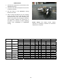
1
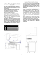
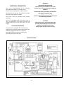
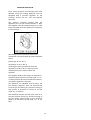
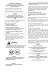
WARNING! IMPORTANT SAFETY INFORMATION Read this instruction booklet before installing and using the appliance. PLEASE READ AND FOLLOW THESE IMPORTANT INSTRUCTIONS FOR THE SAFETY OF YOUR HOME AND OF THE PEOPLE LIVING IN IT. The manufacturer will not be responsible for any damage to property or to persons caused by incorrect installation or improper use of the appliance. Save this Manual for local electrical inspector’s use. Read and save these instructions for future reference. The manufacturer reserves the right to make changes to its products when considered necessary and useful, without affecting the essential safety and operating characteristics. Observe all governing codes, ordinances and regulations. WARNING! If the information in this manual is not followed exactly, a fire or explosion may result causing property damage, personal injury or death. This appliance has been designed for non‐ professional, domestic use only. Do not use this appliance to heat a room. Do not place any pot or pan on the open oven door. The door is made of glass and it can break if loaded with a weight. ‐ Do not store or use gasoline or other flammable substances in the vicinity of this or any other appliance. Before beginning installation, please read these instructions completely and carefully. ‐ WHAT TO DO IF YOU SMELL GAS Do not touch any electrical switch. Do not remove permanently affixed labels, warnings, or plates from the product. This may void the warranty. ‐Please observe all local and national codes and ordinances. Do not use any phone in your building. Please ensure the range is properly grounded. Immediately call your gas supplier from a neighbor’s phone. Follow the gas supplier’s instructions. The installer should leave these instructions with the consumer who should retain for local inspector's use and for future reference. If you cannot reach your gas suppliers, call the fire department. The plug should always be accessible. Do not light any appliance. Installation must conform with local codes or in the absence of codes, the National Fuel Gas Code ANSI Z223.1 / NFPA 54. Electrical installation must be in accordance with the National Electrical Code, ANSI/NFPA70 ‐ latest edition and/or local codes. IN CANADA: Installation must be in accordance with the current CAN/CGA‐B149.1 National Gas Installation Code or CAN/CGA‐B 149.2, Propane Installation Code and/or local codes. Electrical installation must be in accordance with the current CSA C22.1 Canadian Electrical Codes Part 1 and/or local codes. ‐ Installation and service must be performed by a qualified installer, service agency or the gas supplier In Massachusetts: All gas products must be installed by a "Massachusetts" licensed plumber or gasfitter. A "T" handle type manual gas valve must be installed in the gas line connected to this appliance. Installation of any gas‐fired equipment should be made by a licensed plumber. A manual gas shut‐off valve must be installed in the gas supply line ahead of the oven in the gas flow for safety and ease of service. WARNING This appliance shall not be installed with a ventilation system that blow air downward toward the range/rangetop/cooktop; this type of ventilation system may cause ignition and combustion problem with the gas appliance resulting in a personal injury or unintended operation WARNING An air curtain or other overhead range/rangetop/cooktop hood, which operates by blowing a downward airflow onto a range/rangetop/cooktop, shall not be used/installed in conjunction with this gas range/rangetop/cooktop, Warning! This range can tip. Injury to persons could result. Install anti-tip device shipped with range. See Installation Instructions. 1 From the desk of the President Dear new owner of a Bertazzoni product, I want to thank you for choosing one of our beautiful PRO ranges. We know that you have many brands and products to choose from and we are thrilled that you have decided to take onw of your products into your home. We take as much pride in making our ranges as we hope you will in owning them. My family started manufacturing cooking appliances in 1882. Each of our products is a blend of Italian design finess and superior appliance technology. While we can not replace your unique talent at cooking delicious recipes for yourself, your family and your friends, we try our best to make cooking easier, more effective and more fun. BERTAZZONI SpA Via Palazzina 8 42016 Guastalla RE ITALY WWW.BERTAZZONI.COM Our appliances are designed according to the strictest safety and performance standard for the European and the North American market. We follow the most advanced manufacturing philosophy. Each appliance leaves the factory after thorough quality inspection and testing. Our distributors and our service partners are ready to answer any questions you may have regarding how to install, use and care for your Bertazzoni product. This manual will help you learn to use the product in the safest and most effective manner and care for it so that it may give you the highest satisfaction for years to come. The manual also includes directions for the professional installer that will install the product in your home. We recommend using factory‐trained professionals for the delicate task of installing and testing appliances in your home. Please call Customer Service at (800) if you need help locating a factory‐trained professional installer in your area. Models PRO48 6G GAS X LP 01 [MTYKQPU8X2A] Please keep this manual for future use. Grazie! 2 TABLE OF CONTENTS IMPORTANT SAFETY INFORMATION ............................................................................................ 1 WARRANTY AND SERVICE ............................................................................................................ 4 CUSTOMER SERVICE ....................................................................................................................................................... 4 REPLACEMENT PARTS .................................................................................................................................................... 4 PRODUCT SPECIFICATIONS ........................................................................................................... 5 INSTALLING THE LEGS ................................................................................................................... 7 INSTALLING THE WORKTOP FRONTGUARD .................................................................................. 7 INSTALLING THE BACKGUARD ...................................................................................................... 8 INSTALLING THE ANTI‐TIP STABILLTY DEVICE ............................................................................... 9 INSTALLATION REQUIREMENTS .................................................................................................... 9 ELECTRICAL .................................................................................................................................................................... 9 GAS ................................................................................................................................................................................. 9 INSTALLATION ADJACENT TO KITCHEN CABINETS ...................................................................... 10 EXHAUST HOOD INSTALLATION ................................................................................................. 10 ELECTRICAL CONNECTION .......................................................................................................... 11 WIRING DIAGRAM ........................................................................................................................................................ 11 GAS CONNECTION ...................................................................................................................... 12 PRESSURE REGULATOR ................................................................................................................................................ 13 GAS CONVERSION ...................................................................................................................... 14 STEP 1: PRESSURE REGULATOR .................................................................................................................................... 14 STEP 2: SURFACE BURNERS .......................................................................................................................................... 15 STEP 3: MAIN OVEN BURNER ....................................................................................................................................... 15 STEP 4: BROILER BURNER ............................................................................................................................................. 17 STEP 5: VISUAL CHECKS ................................................................................................................................................ 17 STEP 6: MINIMUM FLAME ADJUSTMENT ..................................................................................................................... 18 OVEN BURNER .............................................................................................................................................................. 19 INSTALLATION CHECKLLST .......................................................................................................... 20 FINAL PREPARATION .................................................................................................................. 20 USER MANUAL ........................................................................................................................... 21 ROOM VENTILATION .................................................................................................................. 21 SURFACE BURNER LAYOUT ......................................................................................................... 21 SURFACE COOKING .................................................................................................................... 22 SYMBOLS ...................................................................................................................................................................... 22 SURFACE BURNER OPERATION .................................................................................................................................... 22 TIPS FOR USING BURNERS CORRECTLY ........................................................................................................................ 23 TIPS FOR USING PANS CORRECTLY ............................................................................................................................... 23 TIPS FOR USING ELECTRIC GRIDDLE ............................................................................................ 24 OVEN COOKING .......................................................................................................................... 25 SYMBOLS (LEFT OVEN) ................................................................................................................................................. 25 SYMBOLS (RIGHT OVEN) .............................................................................................................................................. 25 OVEN SHELVES ............................................................................................................................................................. 26 GAS OVEN OPERATION ................................................................................................................................................. 26 CONVECTION COOKING ............................................................................................................................................... 27 COOKING WITH THE GAS BROILER............................................................................................................................... 28 MAINTAINING YOUR RANGE ...................................................................................................... 28 REPLACING THE OVEN LIGHT BULB .............................................................................................................................. 28 COOLING FAN FAILURE ................................................................................................................................................. 28 CLEANING YOUR RANGE............................................................................................................. 29 IMPORTANT APPLIANCE INFORMATION .................................................................................... 31 3 WARRANTY AND SERVICE All Bertazzoni products carry a 2 year parts and labor warranty. Service on all Bertazzoni products shall be carried out by factory‐trained professionals only. For warranty service please contact Customer Service at the numbers indicated below. CUSTOMER SERVICE English/spanish hotline French (866) 905‐0010 (800) 561‐7625 Fax (714) 428‐0040 Email [email protected] Mailing address SERVICEPOWER 1503 South Coast drive Suite 320 Costa Mesa CA 92626 REPLACEMENT PARTS Only Bertazzoni replacement parts may be used in performing service on the appliance. Replacement parts are available from factory authorized parts distributors. PHONE 716 961 7131 FAX 716 856 4779 Reliable Parts PHONE 206 5758818 FAX 206 5750910 AP Wagner Coast PHONE 800 821 0244 4 FAX 604 321 6646 PRODUCT SPECIFICATIONS Dimensions (insert drawings front, side and back Weight Burner power Natural gas LP gas Auxiliary 3750 BTU/h 3750 BTU/h Semi‐rapid 6000 BTU/h 6300 BTU/h Rapid 10400 BTU/h 11400 BTU/h Dual burner (inner) 2730 BTU/h 2900 BTU/h Dual burner ( outer) 15000 BTU/h 16400 BTU/h Oven (left cavity) 14500 BTU/h 14500 BTU/h Broiler (left cavity) 12000 BTU/h 12000 BTU/h Oven (right cavity) 7000 BTU/h 7000 BTU/h 5 WARNING! BEFORE INSTALLATION This appliance shall only be installed by an authorized professional. Do not use aerosol sprays in the vicinity of this appliance while it is in operation This appliance shall be installed in accordance with the manufacturer’s installation instructions. ROOM VENTILATION: An exhaust fan may be used with the appliance; in each case it shall be installed in conformity with the appropriate national and local standards. Exhaust hood operation may affect other vented appliances; in each case it shall be installed in conformity with the appropriate national and local standards. This appliance must be installed in accordance with the norms & standards of the country where it will be installed. The installation of this appliance must conform to local codes and ordinances. In the absence of local codes, Installations must conforms to American National Standards, National Fuel Gas Code ANSI Z223.1 / NFPA 54 or B149.1. TYPE OF GAS This appliance is shipped from the factory for use with propane lp gas. For use with natural gas please follow the conversion procedure described on pg. 14. A step by step conversion procedure is also included with each set of natural gas nozzles. The appliance, when installed, must be electrically grounded in accordance with local codes or, in the absence of local codes, with the National Electrical Code, ANSI/NFPA 70. If local codes permit, a flexible metal appliance connection with the new AGA or CGA certified design, max. 5 feet (1,5 m) long, ½” I.D. is recommended for connecting this appliance to the gas supply line. Do not bend or damage the flexible connector when moving the appliance. GAS PRESSURE The maximum inlet gas supply pressure incoming to the gas appliance pressure regulator is ½ psi (13,8 w.c. or 3.5 kPa). This appliance must be used with the pressure regulator provided. The regulator shall be properly installed in order to be accessible when the appliance is installed in its final location. The pressure regulator must be set for the type of gas to be used. The pressure regulator has ½” female pipe thread. The appropriate fitting must be determined based on the size of your gas supply line, the flexible metal connector and the shutoff valve. The minimum gas supply pressure for checking the regulator setting shall be at least 1“ w.c. (249 Pa) above the inlet specified manifold pressure to the appliance (this operating pressure is 4” w.c. (1.00 kPa) for Natural Gas and 11” w.c. (2.75 kPa for LP Gas). The appliance must be isolated from the gas supply piping system by closing its individual manual shutoff valve during any pressure testing of the gas supply piping system at test pressures equal to or less than ½ psi (3.5 kPa). All opening and holes in the wall and floor, back and under the appliance shall be sealed before installation of the appliance. A manual valve shall be installed in an accessible location in the gas line external to the appliance for the purpose of turning on or shutting off gas to the appliance 6 INSTALLING THE LEGS INSTALLING THE WORKTOP FRONTGUARD Bertazzoni ranges must be used only with the legs properly installed. To increase the clearance between the front edge of the worktop and the burners it is possible to install the worktop frontguard shipped with the appliance. Four height‐adjustable legs are shipped with the range in the polysterene container situated over the appliance. To install the front guard, hold it with the pointed edges looking up. Align the edges of the frontguard with the appropriate receptacles in the bottom of the worktop and press firmly until the frontguard is securely attached to the worktop. Before installing the legs, position the appliance near its final location as the legs are not suitable for moving the appliance over long distances. After unpacking the range, raise it enough to insert the legs in the appropriate receptacles situated on the lower part of the appliance. Lower the range gently to keep any undue strain from legs and mounting hardware. If possible use a pallet or lift jack instead of tilting the unit. ATTENTION: once installed the frontguard may only be removed by disassembling the worktop. Attempting to remove the frontguard without disassembling the worktop will result in permanent damage to the worktop. Adjust leg height to the desired level by twisting the inside portion of the leg assembly until the proper height is reached. Check with a level that the cooktop is perfectly level. 7 Install the front part of the backguard by tightening the 2 central screws from the top and 2 lateral screws from the bottom. INSTALLING THE BACKGUARD The backguard must be installed prior to operation of the appliance for appropriate ventilation of the oven compartment. The supplied backguard is a 2‐part assembly. The box also contains a set of metal screws for securing the backguard to the worktop. Position the back part of the backguard and secure it to the worktop tightening 4 screws from the bottom. Disassemble the backguard and position the front part on the worktop. Align the screw holes with the corresponding holes at the back of the worktop. Connect the back and front part of the upstand. Check for tight assembly. If the holes are not aligned, partially loosen the brackets att the back of the worktop as shown below. 8 INSTALLATION REQUIREMENTS INSTALLING THE ANTI‐TIP STABILlTY DEVICE ELECTRICAL The anti‐tip bracket shipped with the range must be properly secured to the rear wall as shown in the pircture below. A properly‐grounded horizontally‐ mounted electrical receptacle should be installed no higher than 3" (7.6 cm) above the floor, no less than 2” (5 cm) and no more than 8” (20,3 cm) from the left side (facing product). The height of the bracket from the floor must be determined after the range legs have been adjusted to the desired height and after the range has been leveled. Check all local code requirements. Measure the distance from the floor to the bottom of the anti‐tip bracket receptacle on the back of the appliance. GAS Position the two anti‐tip brackets on the wall at the desired height plus 1/8" (0.32 cm). The brackets must be placed at 2”5/16 (6,0 cm) from the side of the range. The distance between the two bracket is 43”1/4 (109.8 cm). An agency‐approved, properly‐sized manual shut‐ off valve should be installed no higher than 3" (7.6 cm) above the floor and no less than 2” (5 cm) and no more than 8” (20.3 cm) from the right side (facing product). Secure the brackets to the wall with appropriate hardware. To connect gas between shut‐off valve and regulator, use agency‐approved, properly sized flexible or rigid pipe. Check all local code requirements. Slide the range against the wall until the brackets are fully inserted into their receptacles on the back of the range. 9 EXHAUST HOOD INSTALLATION This range will best perform when used with PRO line Bertazzoni exhaust hoods. These hoods have been designed to work in conjunction with the Bertazzoni range and have the same finish for a perfect look. INSTALLATION ADJACENT TO KITCHEN CABINETS This range may be installed directly adjacent to existing countertop high cabinets (36" or 91.5 cm from the floor). For maximum performance, the height of the bottom of the hood from the worktop should be between 25 1/2" (65 cm) and 31 1/2" (80 cm). This would typically result in the bottom of the hood being 61 1/2" (156.2 cm) to 67 1/2" (171.5 cm) above the floor. These measurements provide for safe and efficient operation of the hood. For the best look, the worktop should be level with the cabinet countertop. This can be accomplished by raising the unit using the adjustment spindles on the legs. ATTENTION: the range CANNOT be installed directly adjacent to kitchen walls, tall cabinets, tall appliances, or other vertical surfaces above 36" (91.4 cm) high. The minimum side clearance in such cases is 6" (15.2 cm). Before installation of the exhaust hood, consult local or regional building and installation codes for additional specific clearance requirements. Wall cabinets with minimum side clearance must be installed 18" (45.7 cm) above the countertop with countertop height between 35 ½” (90.2 cm) and 37 ¼” (94.6 cm). The maximum depth of wall cabinets above the range shall be 13" (33.0 cm) Refer to the range hood installation instructions provided by the manufacturer for additional information. A B C D E F 48” (122 cm) 36” (91,5 cm) 13” (33,0 cm) 18” (45,7 cm) 35”1/2(90,2 cm) / 37” ¼ (94,6 cm) 6” (15,2 cm) 10 WARNING! ELECTRICAL SHOCK HAZARD ELECTRICAL CONNECTION Disconnect electrical power at the circuit breaker box or fuse box before installing the appliance. This unit is manufactured for a polarized, grounded 120 volt/60 Hz, 16 amp system. Electric power consumption is about 1200 W. Provide appropriate ground for the appliance. The minimum of 102 VAC is required for proper operation of gas ignition systems. Use copper conductors only. Failure to follow these instructions could result in serious injury or death The circuit must be grounded and properly polarized. The unit is equipped witth a SJT power cord. In case of replacement, the power cord shall be replaced with one of the same type, size and length. CAUTION Label all wires prior to disconnecting when servicing controls. Wiring errors can cause improper and dangerous operation. ELECTRICAL GROUNDING Verify proper operation after servicing. This appliance is equipped with a three‐prong plug for your protection against shock hazard and should be plugged directly into a properly grounded socket. Do not cut or remove the grounding prong from this plug. WIRING DIAGRAM 11 MANUAL SHUT‐OFF VALVE GAS CONNECTION THIS VALVE IS NOT SHIPPED WITH THE APPLIANC AND MUST BE SUPPLIED BY THE INSTALLER. All gas connections must comply with national and local codes. The gas supply line (service) must be the same size or greater than the inlet line of the appliance. This range uses a 1/2" NPT inlet (see drawing below for details of gas connection). On all pipe joints use appropriate sealant resistant to gas. The manual shut‐off valve must be installed in the gas service line between the gas hook‐up on the wall and the appliance inlet, in a position where it can be reached quickly in the event of an emergency. This range can be used with Natural or LP/Propane gas. The range is shipped from the factory for use with LP/Propane gas. In Massachusetts: A 'T' handle type manual gas valve must be installed in the gas supply line to this appliance. For natural household installation, the appliance must be converted by the dealer, by a factory‐ trained professional or by a qualified licensed plumber or gas service company. FLEXIBLE CONNECTIONS In case of installation with flexible couplings and/or quick‐disconnect fittings, the installer must use a heavy‐duty, AGA design‐certified commercial flexible connector of at least 1/2" (1.3 cm) ID NPT (with suitable strain reliefs) in compliance with ANSI Z21.41 and Z21.69 standards. Gas conversion is important for safe and effective use of the appliance. It is the responsibility of the dealer and the owner of the range to perform the appropriate gas conversion following the directions of the manufacturer. THE GAS CONVERSION PROCEDURE IS DESCRIBED IN THIS MANUAL AND IN THE PACKAGE CONTAINING THE CONVERSION NOZZLES SHIPPED WITH EVERY RANGE. In Massachusetts: The unit must be installed with a 36" (3‐foot) long flexible gas connector. In Canada: use CAN 1‐6.10‐88 metal connectors for gas appliances and CAN 1‐6.9 M79 quick disconnect device for use with gas fuel. Please provide the service person with this manual before work is started on the range. WARNING! PRESSURE TEST‐POINT STOPPER VALVE DO NOT USE AN OPEN FLAME WHEN CHECKING FOR LEAKS! To avoid gas leaks, the pressure test‐point stopper valve and gasket supplied with the range must be installed on the gas fitting at the back of the range according to the diagram below. Leak testing of the appliance shall be conducted according to the manufacturer's instructions. Before placing the oven into operation, always check for leaks with soapy water solution or other acceptable method. Check for gas leakage with soapy water solution or other acceptable methods in all gas connections installed between inlet gas pipe of the appliance, gas regulator, till to the manual shut‐off valve. 12 PRESSURE REGULATOR Since service pressure may fluctuate with local demand, every gas cooking appliance must be equipped with a pressure regulator on the incoming service line for safe and efficient operation. The pressure regulator shipped with the appliance has has two female threads ½” NPT. The regulator shall be installed properly in order to be accessible when the appliance is installed in its final position. Manifold pressure should be checked with a manometer and comply with the values indicated below: Natural gas 4.0" W.c.P. LP/Propane 11.0" W.C.P. Incoming line pressure upstream from the regulator must be 1" W.c.P. higher than the manifold pressure in order to check the regulator. The regulator used on this range can withstand a maximum input pressure of 1/2 PSI (13,8" w.c. or 3,5 kPa) If the line pressure exceeds that amount, a stepdown regulator is required. The appliance, its individual shut‐off valve, and the pressure regulator must be disconnected from the gas line during any pressure testing of that system at pressures in excess of 1/2 PSI (13,8" w.c. or 3,5 kPa). The individuaL manual shut‐off valve must be in the OFF position during any pressure testing of the gas supply piping system at test pressures equal to or less than 1/2 PSI (13,8" w.c. or 3,5 kPa). 13 STEP 1: PRESSURE REGULATOR APPLIANCE SERVICING The pressure regulator supplied with the appliance is a convertible type pressure regulator for use with LP gas at a nominal outlet pressure of 11” w.c. or Natural Gas at a nominal outlet pressure of 4” w.c. and it is pre‐arranged from the factory to operate with one of these gas/pressure as indicated in the labels affixed on the appliance, package and Instruction booklet. Before carrying any servicing operation disconnect the appliance from gas and electric supply and extra appliance from final installation place in order to have access to the appliance for proper servicing intervention. GAS CONVERSION To convert the regulator for use with other liquid propane Natural Gas: WARNING! Before carrying out this operation, disconnect the appliance from gas and electricity. 1. Unscrew by hand the upper cap of the regulator, remove the white plastic attachment from the cap, reverse its direction and screw it again firmly against the cap. The white plastic attachment has arrows indicating the position for LP gas (LP) and natural gas (NAT). Gas conversion shall be conducted by a factory‐ trained professional. Call the customer service hotline to identify a factory‐trained professional near your home. The gas conversion procedure for this range includes 6 steps: 2. Screw by hand the metal cap in the original position on the regulator. 1. Pressure regulator 2. Surface burners 3. Main oven burner 4. Broiler burner 5. Visual checks prior to closure of oven bottom panel 6. Adjustment of minimum setting The conversion is not completed if all 6 steps have not been concluded properly. Before performing the gas conversion, locate the package containing the replacement nozzle shipped with every range. IMPORTANT: Each nozzle has a number indicating its flow diameter printed on the body. Consult the table on page 20 for matching nozzles to burners. Save the nozzles removed from the range for future use. 14 STEP 3: MAIN OVEN BURNER STEP 2: SURFACE BURNERS To replace the nozzles of the main oven burner, start by removing the bottom panel of the oven. To replace the nozzles of the surface burners, lift up the burners and unscrew the nozzles shipped with the range using a 7 mm {sochet wrench). Replace nozzles using the conversion set supplied with the range or by a Bertazzoni authorized parts warehouse. Each nozzle has a number indicating its flow diameter printed on the body. Consult the table on page 20 for matching nozzles to burners. Loosen the screw located on the right side of the burner and pull out the burner from its support. ATTENTION: pay extra attention to avoid damage to the igniter and thermocouple. Left oven 15 Left oven Unscrew the nozzle located inside the gas fitting using a 7 mm [ socket wrench]. Replace the nozzle using the conversion set supplied with the range or by a Bertazzoni authorized parts warehouse. Each nozzle has a number indicating its flow diameter printed on the body. Consult the table on page 20 for matching nozzles to burners. Do not need air adjustment on the oven burner. Left oven Right oven Right oven 16 STEP 5: VISUAL CHECKS STEP 4: BROILER BURNER Before reinstalling the bottom panel, the following visual check must be performed to ensure that the conversion has been carried out properly and without damage to other components of the range. Loosen the screw and pull out the burner from its support. ATTENTION: pay extra attention to avoid damage to the igniter and thermocouple. Verify that the flame of the oven/broiler burner be completely blue and with regular aspect as shown below. Using a 7 mm [name of the tool] unscrew the nozzle. Replace the nozzle using the conversion set supplied with the range or by a Bertazzoni authorized parts warehouse. Each nozzle has a number indicating its flow diameter printed on the body. Consult the table on page 20 for matching nozzles to burners. A) CONNECTION OF THERMOCOUPLES TO THERMOSTAT The thermocouples for both broiler and main oven burner are connected to the same magnet. Tight gently the two connections alternating action on the two nuts. Do not fully tighten one thermocouple before having started to tighten the second one. Adjust the gap X by setting it to fully open position. B) OVEN IGNITER AND THERMOCOUPLE POSITION The appropriate gap between the tip of the spark plug or thermocouple and the burner shall be approximately 1/8’’. 17 STEP 6: MINIMUM FLAME ADJUSTMENT WARNING! These adjustments should be made only for use of the appliance with natural gas. For use with liquid propane gas, the choke screw must be fully turned in a clockwise direction. SURFACE BURNERS 1. Light one burner at a time and set the knob to the MINIMUM position (small flame). 2. Remove the knob. The tip of the spark plug or thermocouple must fully overlap at least the first gas emission hole of the burner. 3. The range is equipped with a safety valve. Using a small‐size slotted screwdriver, locate the choke valve on the valve body and turn the choke screw to the right or left until the burner flame is adjusted to desired minimum. 4. Make sure that the flame does not go out when switching quickly from the MAXIMUM to the MINIMUM position. After performing all these visual checks, reinstall the bottom panel of the oven compartment and proceed to setting the minimum for each burner. 18 OVEN BURNER 1. Set the oven temperature control knob to the MAXIMUM setting. 2. Close the oven door and operate the oven for at least 10 minutes. 3. Set the knob to the MINIMUM setting Remove the knob. 4. With a slotted screwdriver turn the choking screw (by‐pass screw at the left side of the thermostat bar) and, while observing the flame at the same time through the bottom oven porthole, evaluate the consistency of the flame so it remains on when switching quickly from MINIMUM to MAXIMUM setting. Broiler burner: the broiler burner always operates at maximum, therefore no minimum adjustment is required. Burner Position Injector diam. [mm.] Gas Type Pressure [i.w.c.] Auxiliary Front R Semi-Rapid Rear L & C Front C Rapid Rear R 0,92 0,56 1,17 0,73 1,55 0,98 0,80 0,50 N°2 x 1,30 N°2 x 0,83 NG LP (Propane) NG LP (Propane) NG LP (Propane) NG LP (Propane) NG LP (Propane) 4" 11” 4” 11” 4” 11” 4” 11” 4” 11” 3750 3750 6000 6300 10400 11400 2730 2900 15000 16400 1098 1098 1759 1845 3046 3339 799 849 4394 4804 900 900 1500 1500 2500 2500 900 900 4500 4500 264 264 439 439 732 732 264 264 1318 1318 1,85 1,10 1,70 0,98 1,25 0,75 NG LP (Propane) NG LP (Propane) NG LP (Propane) 4” 11” 4” 11” 4” 11” 14500 14500 12000 12000 7000 7000 4248 4248 3516 3516 2051 2051 3500 3500 Only Max Only Max 2400 2400 1025 1025 Only Max Only Max 703 703 Front L Inner Dual Burner Front L Outer Oven (left cavity) Broiler (left cavity) Oven (right cavity) Oven Left downside Oven Left upside Oven Right downside 19 Max Rate [BTU/h] [W] Min Rate [BTU/h] [W] By-pass diam. [mm] Regulated 0,29 Regulated 0,36 Regulated 0,47 Regulated 0,29 Regulated 0,65 Regulated 0,54 No by-pass No by-pass Regulated 0,48 INSTALLATION CHECKLlST FINAL PREPARATION 1. Is the range mounted on its legs? Before using the oven, remove any protective wrap from the stainless steel. 2. Is the backguard securely connected? All stainless steel body parts should be wiped with hot, soapy water and with a liquid stainless steel cleanser. 3. Has the anti‐tip device been properly installed? If buildup occurs, do not use steel wool, abrasive cloths, cleaners, or powders! If it is necessary to scrape stainless steel to remove encrusted materials, soak with hot, wet cloths to loosen the material, then use a wood or nylon scraper. Do not use a metal knife, spatula, or any other metal tool to scrape stainless steel! Scratches are almost impossible to remove. 4. Does the clearance from the side cabinets comply with the manufacturers directions? 5. Is the electricity properly grounded? 6. Is the gas service line connected following the directions of the manufacturer? Before using the oven for food preparation, wash the cavity thoroughly with a warm soap and water solution to remove film residues and any dust or debris from installation, then rinse and wiped dry. 7. Have all the proper valves, stoppers and gasket been installed between the range and the service line? 8. Has the gas connection been checked for leaks? 9. Has the range been set for the type of gas available in the household? 10. Is the ignition of all oven burners functioning properly? 11. Is the air flow to the over and broiler burners properly adjusted? 12. Does the flame appear sharp blue, with no yellow tipping, sooting or flame lifting? 13. Has the minimum setting for all burners been adjusted? 14. Is the oven and broiler ignition working properly? 15. Does the oven light work properly? 20 USER MANUAL SURFACE BURNER LAYOUT IMPORTANT: Take care of reset all worktop/oven/broiler burners controls in OFF position after use of the appliance. Reflect names from brochure 1. Small Burner 2. Medium burner 3. Rapid burner 4. Dual burner (Power burner) 5. Griddle Model PRO486GGASX LP 01 [MTYKQPU8X2A] WARNING! Do not to cover the holes inside the oven with aluminium foil. Do not to cover the worktop with aluminium foil. Do not store any flammable object or objects under pressure in the storage compartment. Keep the area of operation of the range free from combustible materials, gasoline and other flammable vapors and liquid. Do not store dangerous or flammable materials in the cabinets above the appliance, since this may result in a potential fire hazard. Do not use the appliance for space heating. Do not use aerosol sprays in the vicinity of the appliance while cooking. Do not sit or step on the oven door. Do not use oven compartment for storage. ROOM VENTILATION The use of a gas cooking appliance generates heat and humidity in the room where it is installed. Proper ventilation in the room is needed. Make sure the kitchen is equipped with a range hood of appropriate power (400 CFM minimum). Activate the exhaust fan/range hood when possible. Intensive and continuous use of the appliance may require additional ventilation, for example by opening a window. 21 SURFACE COOKING SURFACE BURNER OPERATION IMPORTANT. Take care of reset all worktop/oven/broiler burners controls in OFF position after use of the appliance. THERMOCOUPLE SAFETY VALVE SYMBOLS Each surface burner of a Bertazzoni range is equipped with a thermocouple safety device. The thermocouple opens the flow of gas to the burner only when hot. Should the flame go off, the thermocouple will immediately close the gas flow to the burner eliminating any risk to your home. For faster activation of the thermocouple, always light the burners on maximum power. This will allow the thermocouple to reach the optimum temperature in the fastest time. ELECTRIC IGNITION To activate the electric ignition, simply turn the control knob counter‐clockwise to maximum power ( position). Press the knob to start the flow of gas and the ignition spark. The spark will released at the metal tip of the white ceramic pin located on the side of the burner. Once the flame is on, release the control knob gently. Burner position (in this case front right burner). If the flame turns off, repeat the above procedure. The dual power‐burner is composed by two burners (inside and outside). Each burner is activated by a separate control knob. The two burners can be operated separately or together for maximum power. To activate the power‐ burner, turn on the central burner first, then turn on the external ring. Maximum temperature setting / Recommended control knob position for burner ignition ATTENTION: do not ignite burners if the black burner cap is not installed or not centred. The flame will be irregular. Minimum temperature setting MANUAL IGNITION Manual ignition is always possible even when the power is cut off or in the event of power failure. Turn the control knob counter‐clockwise to the MAXIMUM position. Light the flame with a kitchen lighter or with a match. 22 TIPS FOR USING PANS CORRECTLY TIPS FOR USING BURNERS CORRECTLY WARNING! ATTENTION! KEEP CHILDREN AT A SAFE DISTANCE FROM THE APPLIANCE DURING OPERATION. Always ensure that bottom and handles of pans do not protrude from the worktop. DO NOT ALLOW CHILDREN TO OPERATE THE APPLIANCE. When cooking with flammable fat such as oil, do not leave the range unattended. IMPORTANT. Take care of reset all worktop/oven/broiler burners controls in OFF position after use of the appliance. Use pots of the appropriate size on each burner following the indication of the diagram below. 1. Always check that the burner caps are properly installed before operation. Burner Small Recommended pan size inches (mm) 3½”‐51/2”(90 – 140) Medium 51/2”‐ 101/4”(140 – 260) Large 71/8”‐ 101/4” (180 – 260) Dual burner 82/3”‐101/4” (220 – 260) When boiling liquids, turn the knob to the MINIMUM position once boiling is reached to avoid overflow. . 2. Verify that the flame of the worktop burners be completely blue and with regular aspect as shown below. Always use pots with matching lid. Dry the bottom of pans before operation. Use pots with a flat, thick bottom (except for wok cooking). WOK COOKING: always use the wok adapter supplied with the range. Wok pan external diameter shall not be smaller than 10” (25cm) and larger than 16” (40cm). SIMMERING: use the simmer ring supplied with the range. 3. Always adjust the burner flame so it does not extend beyond the edge of the pan. 23 TIPS FOR USING ELECTRIC GRIDDLE Griddle cooking recommendations WARNING! FOOD Eggs The griddle element is hot after use. Allow sufficient time for griddle components cool before cleaning. Bacon; Breakfast Sausage Toasted Sandwiches Boneless Chicken Breasts Boneless Pork Chops, ½” thick Ham Slices, ½” thick Pancakes; French Toast Potatoes; Hash Browns The electric griddle element is rated 120 volts AC 1100 watts. Seasoning the griddle Before using the griddle for the first time, it must be seasoned. If the griddle has not been used for a period of time, it should be reseasoned. To season the gridlle: 1. clean the griddle thoroughly with hot, soapy water to remove any protective coating. 2. rinse with a mixture of 1 quart water and 1 cup white vinegar. Dry thoroughly. 3. Pour 1 teaspoon vegetable oil into the center of the griddle. Do not use corn oil as it gets sticky. Rub the oil over the entire surface of the griddle using a heavy cloth. 4. Turn the control knob to a maximum setting (7). Turn the heat off when the oil begins to smoke. Allow the griddle to cool. 5. Repeat step 3. Be sure to cover the entiresurface with the oil 6. Repeat step 4. Allow the griddle to cool. Wipe the entire surface of the griddle using a heavy cloth. Apply a very thin layer of vegetable oil. The griddle is now ready to use. Use Press and turn the knob anti‐clockwise to the selected position Pre‐heat at the maximum temperature, (7 position) for 15 minutes, then place the food on the griddle and cook to the desired temperature. The activation of the griddle is shown by the indicator light which is also found on the front panel of the appliance. 24 KNOB POSITION SETTING 5-6 300°F to 325°F (150°C to 160°C) 6 350°F to 375°F (177°C to 190°C) 5-6 325°F to 350°F (160°C to 177°C) 6 350°F to 375°F (177°C to 190°C) 6 350°F to 375°F (177°C to 190°C) 6 350°F to 375°F (177°C to 190°C) 6 350°F to 375°F (177°C to 190°C) 7 375°F to 400°F (190°C to 205°C) OVEN COOKING IMPORTANT. Take care of reset all worktop/oven/broiler burners controls in OFF position after use of the appliance. IMPORTANT: Does not obstruct the oven/broiler’s flow of combustion outlets located in the backguard fixed in the back side of the worktop since this can produce poisonous excess of carbon monoxide. Convection fan and oven compartment light switch Oven compartment light switch for baking or broiling SYMBOLS (RIGHT OVEN) SYMBOLS (LEFT OVEN) Thermal bake selector Recommended control knob position for burner ignition Thermal bake selector 220F Mimimum oven temperature setting 440F Broiler selector Maximum oven temperature setting Recommended control knob position for burner ignition 275F Mimimum oven temperature setting 500F Maximum oven temperature setting Oven on/off Oven status indicator. 25 Oven compartment light OVEN SHELVES GAS OVEN OPERATION Bertazzoni ranges are equipped with commercial grade shelves and a enamel cooking tray. Shelves are mounted on the appropriate guides situated on the sides of the oven compartment. Insert the shelf between top and bottom guide in any of the 5 positions available. IMPORTANT: Does not obstruct the oven/broiler’s flow of combustion outlets located in the backguard fixed in the back side of the worktop since this can produce poisonous excess of carbon monoxide. THERMOCOUPLE SAFETY VALVE To keep the oven as clean as possible, cook meat on the tray . Bertazzoni gas ovens are equipped with a thermocouple safety device and a thermostat to set the proper cooking temperature. When available, always follow recipe book directions. Personal experience will help to determine any variations in the values reported in the table. In any case, it is recommended to follow the instructions of the specific recipe being used. The thermocouple opens the flow of gas to the burner only when hot. Should the flame go off, the thermocouple will immediately close the gas flow to the burner eliminating any risk to your home. For faster activation of the thermocouple, always light the burners on maximum power. This will allow the thermocouple to reach the optimum temperature in the fastest time. Verify that the flame of the oven/broiler burner be completely blue and with regular aspect as shown below. ATTENTION! When using the oven for the first time it should be operated for 15‐30 minutes at a temperature of about 500°F/260°C (left oven) or 440°F/227°C(right oven) without cooking anything inside in order to eliminate any moisture and odours from the internal insulation. 26 ELECTRIC IGNITION CONVECTION COOKING Bertazzoni gas oven are equipped with a CONVECTION fan. WARNING! Always keep the oven door open when lighting the oven. In convection mode, the fan situated at the back of the oven compartment creates horizontal forced‐air circulation. The advantages of convection cooking are: Warning: Do not use the gas oven or broiler in case of electric power failure Open the oven door, with oven/broiler thermostat knob in the OFF position, press the thermostat knob for about 1 sec., release it immediately and turn it to the desired oven temperature; in the case when the ignition of oven burner does not happen successfully (the oven burner does not remain alight), turn the thermostat knob in the OFF position again and repeat the whole sequence described here one minute later. 1. uniform distribution of heat throughout the oven cavity (meat no longer needs to be turned while roasting) The gas oven operation is indicated by a blue light on the left side of the control panel. To activate the convection fan use the selector placed on control panel. 2. cooking different types of food at the same time, without flavour transmission from one dish to the other. Pre‐heating the oven is not necessary. For delicate pastry baking, it is recommended to heat the oven before inserting the pastry trays. Before closing the oven door, visually check that the flame is on through the portholes on the oven compartment bottom panel. If no flame is visible, repeat the procedure. After lighting the burner and setting the desired temperature, wait about 15 minutes before putting food in to preheat the oven. WARNING If the oven burner flame is extinguished accidentally during operation, turn the temperature control knob counter‐clockwise to the off position. Wait at least 60 seconds before attempting to light the oven again. IMPORTANT: In case of electric power failure reset oven/broiler controls in off position. Oven/broiler burners cannot operates till when electric power to the appliance has been restored. 27 COOKING WITH THE GAS BROILER Verify that the flame of the oven/broiler burner be completely blue and with regular aspect as shown below. IMPORTANT: Does not obstruct the oven/broiler’s flow of combustion outlets located in the backguard fixed in the back side of the worktop since this can produce poisonous excess of carbon monoxide. MAINTAINING YOUR RANGE REPLACING THE OVEN LIGHT BULB WARNING! Disconnect power before servicing unit. ELECTRIC IGNITION Open the oven door, with oven/broiler thermostat knob in the OFF position, press the thermostat knob for about 1 sec., release it immediately and turn it to the broile r position; in the case when the ignition of broiler burner does not happen successfully (the broiler burner does not remain alight), turn the thermostat knob in the OFF position again and repeat the whole sequence described here one minute later. To replace the oven light bulb, unscrew the protection cap that projects out inside the oven. Spare bulbs are available at factory‐authorized parts resellers listed on page 4. Alternatively use commercial bulbs type [list SPECS] Before closing the oven door, visually check that the flame is on through the portholes on the oven compartment bottom panel. If no flame is visible, repeat the procedure. ATTENTION: always use the small wire shelf inside the enamel tray supplied with the range; position the tray on the top oven shelf. COOLING FAN FAILURE Gas broiler operation is indicated by the indicator on the left side of the control panel. Bertazzoni ranges are equipped with a cooling fan. The fan starts operating each time the oven knob is on a position different from 0 (zero). IMPORTANT: when broiling food keep the door closed. IMPORTANT: In case of electric power failure reset oven/broiler controls in off position. Oven/broiler burners cannot operates till when electric power to the appliance has been restored. The fan circulates the air between the control panel and the oven door, allowing the control panel and the oven door to remain cool while cooking. Malfunction of the cooling fan is indicated by the FAN FAILURE light situated at the left side of the control panel. If the light is on, turn off all burners as soon as possible and call the customer service hotline to schedule service by a factory‐ trained professional. 28 Cleaning Enamel: enamelled parts should be cleaned frequently with awarm soap and water solution applied with a soft sponge or wipe. Never use abrasive powders or liquids! Do not leave acid or alkaline substances on the enamelled parts (such as vinegar, lemon juice, salt, tomato sauce, etc.). Use a rubber spatula to remove fat residues. CLEANING YOUR RANGE ATTENTION: during cleaning operation never move the appliance from its foreseen original installation position. ATTENTION! Never use abrasive cleaners! Scratches on the stainless steel surfaces are permanent. Cleaning glass door: clean the glass using a non‐ abrasive sponge or wipe with a warm soap and warm water solution. Use a rubber spatula to remove fat residues. Do not clean the range when hot! Cleaning after installation: use a stainless steel cleaning product or wipe to eliminate the glue residues of the blue protection film after removal. Cleaning the inside of the oven glass: Oven feature is the ability to remove the inner glass. After you open the door completely and lock the hinges (fig. 1) unhook the engagements shows the figure (2‐3) lift and remove the inner glass (fig. 4) and then clean the crystal. Such an operation is to be performed in cold oven and with a damp cloth, taking care not to use abrasives. To reassemble the glass do the opposite making with the same orientation that has been disassembled, remembering that the smooth part both in vista and the remains inside the screen‐printed glass oven door. Once you have reassembled the glass block with the engagements and unlocking hinges. Cleaning the worktop: periodically clean the burner heads, the cast iron pan supports and the burner caps using warm water. Remove burned food and fat residues with a rubber spatula . If food residue prevent the smooth operation of the control knobs, call the customer servce hotline to schedule service by a factory‐trained professional. Cleaning stainless steel: for best results use a stainless steel cleaner product with a soft sponge or wipe. Alternatively use a soft sponge or cloth with a warm soap and water solution. Never use abrasive powders or liquids! Caution: do not loosen the hinges if the inner glass is not mounted on the door. Cleaning the burner caps: lift the burner caps from the burner heads and wash them in a warm soap and water solution. Dry thoroughly before using them again. Before reinstalling them on the burner head, check that the gas flow holes are not clogged with food residues or cleaning product residues. Clean the inside of the oven: To facilitate intensive cleaning of the oven is easy to disassemble the door by following the below instructions. After you open the door completely and lock the hinges (fig. 1),put the door in a semi‐ open position and using both hands pull it towards you until it is released from the attachment.. To reassemble the door operate in reverse order. They are also easily off the side grids, by unscrewing the nuts that fasten the oven. ATTENTION: while cleaning the door, avoid spillage of food resideues and cleaning products in the venting holes situated on the top side of the door. To clean the inside of the oven door, call a factory‐trained professional. Cleaning the griddle: Thoroughly clean the griddle of grease and food particles, using a square‐edged spatula, while it is still hot. Remove drip tray and discard grease into a grease resistant container for disposal. Wash drip tray with hot soapy water, rinse and dry. Wipe the griddle with a dry, heavy, coarse cloth to remove any remaining residue and food particles. Wash with hot soapy water, rinse and dry . Once the griddle has cooled, rub the surface lightly with vesetable oil. Do not use corn oil or cooking sprays as they get sticky. If the gridlle is cleaned with anything other than a dry, heavy, coarse cloth, it will need to be reseasoned. Never flood the hot griddle with cold water. This could cause the griddle to crack or warp. ATTENTION: for further details about cleaning of the appliance, please contact your appliance retailer. 29 30 IMPORTANT APPLIANCE INFORMATION MODEL ______________________________________________________________ DATE INSTALLED _______________________________________________________________ DEALER _______________________________________________________________ _______________________________________________________________ _______________________________________________________________ ________________________________________________________________ _______________________________________________________________ ________________________________________________________________ INSTALLER SERVICER 31 SPARE PARTS LIST NUMBER COMPONENT 1 1 1 9 11 18 38 38 80 81 82 83 84 105 106 107 108 109 117 120 130 138 160 203 204 205 206 207 207 274 311 329 329 385 385 389 389 424 424 425 426 427 429 430 430 441 442 443 444 444 446 446 473 478 544 546 551 561 562 564 564 565 566 6010008 601785 910588 3070593 202631 202945 306031 306031 504791 504792 504793 504795 504801 202629 2020032 202721 202551 1080417 101481 101048 404541 2020004 202526 410915 410918 410914 410916 308034 308034 202473 301156 309181 309181 306029 306030 301077 301077 415098 415103 415096 415097 415077 415084 415099 415100 404042 404539 404497 405095 405095 405128 405129 408077 410623 504781 505013 503159 508045 508046 508043 508043 508047 508048 DESCRIPTION PRO486GGASX-LP 01 - GAS COOKER WIRE T-ZERO CIRCUIT DIAGRAM PAN SUPPORT BUMPER KIT BADGE BURNERS FLASK BURNERS FLASK THERMOSTAT CLIP THERMOSTAT CLIP COVER FOR SMALL FLAME SPREADER COVER FOR MEDIUM BURNER COVER FOR RAPID BURNER COVER OUT FOR ULTRA RAPID FLAME SPREADER BRASS BURNER CAP UP SUPPORT FOR AXIAL COOLIN FAN DOWN SUPPORT FOR AXIAL COOLIN FAN UP SUPPORT FOR AXIAL COOLIN FAN RIGHT SUPPORT FOR AXIAL COOLIN FAN INSIDE FLAP DOOR PROTECTION FOR FAN ASSISTED OVEN BLACK OVEN DRIP TRAY GRID FOR OVEN RIGHT DISHWARMER BOTTOM BRIDLE FOR FIXING GAS VALVES PROFILE FOR GLASS DOOR PROFILE FOR GLASS DOOR PROFILE FOR GLASS DOOR PROFILE FOR GLASS DOOR BUMPER BUMPER CROSS MEMBER SCREW 4,2X30 INSIDE DOOR PAN COMPARTMENT SPACER INSIDE DOOR PAN COMPARTMENT SPACER SPRING FOR SPARK PLUG SPRING FOR SPARK PLUG DUAL SCREW M5X35 FOR HANDLE SCREW M5X35 FOR HANDLE SPARK PLUG FOR DUAL BURNER IN SPARK PLUG FOR DUAL BURNER OUT SPARK PLUG 350MM SPARK PLUG 800MM SPARK PLUG SPARK PLUG 1600mm ACCUMULATOR 4U ACCUMULATOR 6U SIDE GRID FOR OVEN SHELF OVEN GRID FOR TRAY OVEN DOOR HINGE FIX PART OVEN DOOR HINGE FIX PART OVEN DOOR HINGE OVEN DOOR HINGE REDUCTION GRID FLAP DOOR S.STEEL OVEN BURNER SUPPORT FOR GRILL BURNER NOZZLE THERMOSTAT GAS THERMOCOUPLE MM300 THERMOCOUPLE MM600 THERMOCOUPLE OVEN BURNER THERMOCOUPLE OVEN BURNER THERMOCOUPLE MM800 THERMOCOUPLE ULTRA-RAPID BURNER INT QUANTITY 2 1 1 1 2 1 2 2 1 3 1 1 1 1 1 1 1 1 1 1 2 1 1 1 1 1 1 2 2 1 8 2 2 6 1 2 2 1 1 3 2 1 2 1 1 4 2 1 2 2 2 2 1 1 1 1 1 2 2 1 1 1 1 566 567 570 572 611 612 616 620 623 636 646 647 648 649 649 649 667 670 671 672 675 702 715 760 761 762 764 871 884 885 886 887 917 927 929 930 940 943 965 972 972 988 1041 1043 1044 1046 1047 1143 1406 1407 1411 1412 1413 1415 1415 1416 1419 1421 1508 1510 1602 1603 1603 1603 1608 1609 1609 508048 508042 508040 504782 603020 603022 606070 602039 608046 402158 415086 602043 601991 608047 608047 608047 503157 504787 504788 504789 504790 408084 604063 510316 510317 510318 510320 108709 502179 502148 502180 502150 200327 202474 202586 202214 201197 308041 408075 202360 202360 501780 401904 401905 401906 401961 401962 910916 403606 406396 411120 411122 602033 602042 602042 411123 411121 406395 410922 410923 2100034 309119 309119 309119 501761 505056 505056 THERMOCOUPLE ULTRA-RAPID BURNER INT THERMOCOUPLE GRILL BURNER THERMOSTAT ADAPTER OVEN BURNER OVEN CONVECTION FAN COOLING FAN RESISTANCE 1100W COMMUTATOR OVEN BULB WITH HOLDER BACK FIBER GLASS T-ZERO MODULE ENERGY REGULATOR TERMINAL SEPARATOR SMALL WARNING LIGHT SMALL WARNING LIGHT SMALL WARNING LIGHT THERMOSTAT SMALL FLAME SPREADER MEDIUM BURNER HEAD RAPID BURNER HEAD ULTRA RAPID FLAME SPREADER ADAPTER FOR WOK BURNER PAN SUPPORT DAISYCHAIN SWITCH SMALL BURNER MEDIUM BURNER RAPID BURNER ULTRA-RAPID BURNER BLACK COVER GAS VALVE BY PASS 029 GAS VALVE BY PASS 036 GAS VALVE BY PASS 047 GAS VALVE BY PASS 065 STAINLESS STEEL SIDE VERTICAL VENT RIGHT VERTICAL VENT FEET SUPPORT FIXING FOR WORK TABLE BUMPER CAST IRON PAN SUPPORT 2 BURNERS WORK TABLE FIXING WORK TABLE FIXING ALL.TUBE FOR OVEN BURNER RIGHT GAS VALVE KNOB GAS THERMOSTAT KNOB ELECTRIC KNOB DUAL IN KNOB DUAL OUT KNOB UPSTAND KIT OVEN HANDLE OVEN DOOR GLASS GASKET FOR OVEN FRONT 3 SIDE GASKET FOR OVEN FRONT 3 SIDE THERMOSWITCH FOR COOLING FAN THERMOSWITCH FOR COOLING FAN THERMOSWITCH FOR COOLING FAN GASKET FOR OVEN FRONT ONE SIDE GASKET FOR OVEN FRONT 1 SIDE INNER OVEN GLASS STAINLESS STEEL OVEN DOOR LEFT STAINLESS STEEL OVEN DOOR RIGHT CONTROL PANEL BRIDLE FOR FIXING GAS VALVES/THERMOSTAT BRIDLE FOR FIXING GAS VALVES/THERMOSTAT BRIDLE FOR FIXING GAS VALVES/THERMOSTAT ALL.TUBE FOR OVEN BURNER SUPPORT FOR OVEN BURNER NOZZLE SUPPORT FOR OVEN BURNER NOZZLE 1 1 2 1 1 2 1 1 3 1 1 1 1 1 1 1 1 1 3 1 1 1 1 1 3 1 1 1 2 3 1 1 2 1 1 2 2 4 3 4 4 1 5 2 2 1 1 1 1 2 1 1 1 1 1 2 2 1 1 1 1 2 1 1 1 1 1 1614 1615 1616 1617 1622 1622 1624 1626 1627 1628 1631 1639 1641 1644 1645 1646 1685 1686 1687 1688 1705 1705 1800 1801 1802 1805 1806 2016 2016 2017 2018 2031 2032 2053 2054 2057 2097 2098 2099 2100 2107 2130 2151 2152 2153 2170 2171 2172 2186 2187 2188 2190 2191 2192 2200 2235 4106 4276 4286 4287 4301 4302 5140 201237 202478 402435 608045 608025 608025 200477 201196 501781 501759 501635 202587 201177 414058 414052 501762 201166 201180 202658 202484 410753 410753 501640 501782 501641 5010066 5010065 101485 101485 101486 101487 101408 101385 101400 101401 101399 101388 202437 202497 308036 308041 201159 101402 202483 202471 202482 202441 202475 202485 201179 201178 201181 200370 200369 200367 202481 405078 403612 406411 406412 200328 200329 504780 BACK PANEL CONTROL SUPPORT FIBER GLASS SMALL BLUE BUD SMALL RED BUD SMALL RED BUD WORK TABLE FIXING FOR GAS PIPE GAS COLLECTOR TUBE FOR RIGHT FRONT BURNER TUBE FOR RIGHT BACK BURNER LEFT VERTICAL VENT BACK PANEL RIGHT S.STEEL LEG BASE FOR LEGS GRILL THERMOSTAT TUBE REAR VENT STACK FRONT VENT STACK BACK ENCLOSURE METAL PANEL BACK ENCLOSURE METAL PANEL RIGHT OVEN GLASS SUPPORT OVEN GLASS SUPPORT REAR CENTRAL TUBE TUBE FOR LEFT BACK BURNER FRONT CENTRAL TUBE TUBE FOR EXTERNAL DUAL BURNER TUBE FOR INTERNAL DUAL BURNER OVEN SIDE PANEL BLACK OVEN SIDE PANEL BLACK OVEN SIDE PANEL BLACK OVEN SIDE PANEL BLACK UPPER PART FOR BODY LEFT BACK OVEN BODY OVEN TOP PANEL BLACK RIGHT BACK PANEL FRONT PANEL MUFFLE OVEN BOTTOM PANEL BLACK OVEN BURNER BASE OVEN BASE BUMPER BUMPER GRILL PROTECTION OVEN BOTTOM PANEL BLACK OVEN BURNER BASE RIGHT RIGHT OVEN BASE PARETI LAT BACK PANEL FOR DISHARMER COMPARTMENT BACK PANEL FOR DISHARMER COMPARTMENT FLASK CARTER CRANKCASE RESISTANCE CARTER FIBER GLASS FOR GRIDDLE GRIDDLE SUPPORT GRIDDLE DIRP TRAY BATTEN PLATE MUFFLE CROSS MEMBER HINGE FOR FLAP DOOR OVEN DOOR HANDLE RIGHT OVEN DOOR GLASS RIGHT INNER OVEN GLASS RIGHT RIGHT SIDE PROFILE LEFT SIDE PROFILE OVEN GRILL 1 1 2 1 1 1 1 2 1 1 1 1 1 4 4 1 3 3 1 1 2 2 1 1 1 1 1 1 1 1 1 1 1 1 1 1 1 1 1 2 4 2 1 1 1 2 1 1 2 1 1 1 1 1 1 2 4 1 2 1 1 1 1 39 BERTAZZONI SpA Via Palazzina 8 42016 Guastalla RE ITALY WWW.BERTAZZONI.COM 3100023 40