1
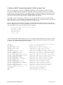
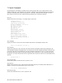
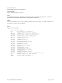
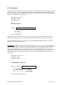
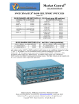
September 2009
PRO SWITCHING SYSTEM PLUS
Part Numbers
Rack Mount Chassis
SNMP Controller Card
RS232 Controller Card
Logic-only Controller Card
RJ45 CAT-5 A/B Switch Card
RJ45 CAT-6 A/B Switch Card
RJ45 CAT-6 Dual-Port A/B Switch Card
Video - F Connector, 75 Ohm A/B Switch Card
DB25 A/B Switch Card
DB9 A/B Switch Card
DB15 A/B Switch Card
Fiber Optic A/B Switch Card - SC
Fiber Optic A/B Switch Card - ST
AC Power A/B Switch Card - 1IN/2OUT (120 VAC)
AC Power A/B Switch Card - 1IN/2OUT (240 VAC)
AC Power A/B Switch Card - 1IN/2OUT (120 VAC)
AC Power A/B Switch Card - 1IN/2OUT (240 VAC)
AC Power A/B Switch Card - 2IN/1OUT (120 VAC)
Blank Rear Panel
External Power Supply Module
CUSTOMER
SUPPORT
INFORMATION
SM960A
SM962A
SM963A
SM964A
SM978A
SM979A
SM980A
SM976A
SM965A
SM966A
SM967A
SM977A-SC
SM977A-ST
SM968A
SM970A
SM969A
SM971A
SM973A
SM981
SM961A - PS
4U 19” Chassis
Includes MIB file & SwitchCenter GUI
Supports 10 GbE
Supports 10 GbE
Switches All 25 Leads
Switches All 9 Leads
Switches All 15 Leads
Full Duplex, Multimode Fiber
Full Duplex, Multimode Fiber
with SNMP reporting
with SNMP reporting
with SNMP reporting
Covers 1 empty slot in Chassis
1 per chassis, or 2 for redundant power
Order toll-free in the U.S.: 877-877-BBOX (outside U.S. call 724-746-5500)
FREE technical support, 24 hours a day, 7 days a week: Call 724-746-5500 or fax 724-746-0746
Mail order: Black Box Corporation, 1000 Park Drive, Lawrence, PA 15055-1018
Web site: www.blackbox.com • E-mail: [email protected]
Federal Communications Commission (FCC) Statement
This equipment generates, uses, and can radiate radio frequency energy and if not
installed and used in accordance with the instruction manual, may cause interference to
radio communications. It has been tested and found to comply with the limits for a Class
A computing device in accordance with the specifications in Subpart J of Part 15 of FCC
rules, which are designed to provide reasonable protection against such interference when
the equipment is operated in a commercial environment. Operation of this equipment in
a residential area is likely to cause interference, in which case the user at his own expense
will be required to take whatever measures may be required to correct the interference.
Contents
Chapter
1. Specifications
Page
3
2. Introduction
4
3. Configuration
5
4. Installation
8
5. Operation
9
6. SNMP/Web Setup
13
7. Console Commands
14
8. Web Interface
18
9. MIB Path Summary
20
PRO SWITCHING SYSTEM PLUS
Page 2 of 24
1. Specifications
Connectors:
RJ45 A/B SWITCH CARDS – SM978A & SM979A (3) RJ45 connectors; SM980A (6) RJ45 connectors
FIBER OPTIC A/B SWITCH CARD – SM977A-SC (3) duplex SC; SM977A-ST (6) ST
DB25 A/B SWITCH CARD – (3) DB25 female connectors
DB15 A/B SWITCH CARD – (3) DB15 female connectors
DB9 A/B SWITCH CARD – (3) DB9 female connectors
CONTROLLER CARD – (1) RJ45, (2) RJ11, (2) Two-Position DC Power Entry, (2) Two-Position Alarm Contact
Terminal Block
AC POWER A/B SWITCH CARD – 1IN 2OUT CARDS (1) IEC320 male and (2) IEC320 female; 2IN 1 OUT
CARD (2) IEC320 male and (1) IEC320 female
Indicators:
A/B SWITCH CARDS – (2) LED, one for A, one for B
CONTROLLER CARD – (3) LED, two for power, one for status, (2) Alarm Relay Contacts
Switches:
A/B SWITCH CARDS – (1) momentary toggle switch
CONTROLLER CARD – (1) momentary toggle switch, (2) 8-position dipswitch, (1) momentary push-button switch
4U RACK – (1) key-lock switch
Power:
RJ45, DB9 & DB15 A/B SWITCH CARDS – 12 VDC, 15 mA normal, additional 80 mA while switching.
FIBER OPTIC A/B SWITCH CARD – 12 VDC, 15 mA in A position, 95 mA max in B position, additional 20 mA
while switching.
DB25 & AC POWER A/B SWITCH CARDS – 12 VDC, 15 mA normal, additional 200 mA while switching.
CONTROLLER CARD – 12 VDC, 50 mA normal, additional 30 mA while switching, and an additional 250 mA
with SNMP module.
The 4U rack may be powered with one or two external 12 VDC, 5 A, regulated supplies.
The external power supply has an IEC input socket, for 100 – 240 VAC, 47 – 63 Hz INPUT, with a 12 VDC, 5 A,
regulated OUTPUT.
Environment:
TEMPERATURE
HUMIDITY
ALTITUDE
0° to 50° C operating, -40° to 70° C non-operating
0 to 95% non-condensing
40,000 ft maximum
Rack Size:
RACK – 7.0” H x 19” W x 6.5” D (not including handles and connectors)
RJ45 A/B SWITCH CARDS – one slot (0.937 inches wide)
FIBER OPTIC A/B SWITCH CARDS – one slot (0.937 inches wide)
DB9, DB15, DB25 A/B SWITCH CARDS – one slot (0.937 inches wide)
CONTROLLER CARDS – one slot (0.937 inches wide)
AC POWER A/B SWITCH CARDS – two slots (1.874 inches wide)
The Pro Switching System Plus rack has 18 slots. Slot 18 is reserved for future expansion.
PRO SWITCHING SYSTEM PLUS
Page 3 of 24
Rear View with Controller Card and a selection of A/B switch cards installed: (3) DB25, (3) RJ45 and (2)
AC power cards.
2. Introduction
The Pro Switching System Plus is a 4U high 19 inch rack style switching product that supports multiple A/B switch
cards, each of which connects port A or port B to port C through latching telecommunication relays or fiber optic
switching mechanisms. The rack has 18 slots, one of which is reserved for future use. The Controller Card requires
one slot, leaving 16 slots for any mix of A/B switch cards. Each A/B switch card can be individually switched, or
the entire rack can be switched from the Controller Card. The 4U rack has a key lock switch to enable and disable
manual switching (disables the front panel toggle switches). The Controller Card has two RJ11 ports that can be
used to daisy chain up to 255 racks, thus allowing a single point of control for all the racks in the system. The
Controller Card can also be operated using a +/- 12 VDC signal, or via a remote toggle switch. When used in this
manner, the maximum number of racks that can be daisy chained together is limited to 64 racks.
The Controller Card is available in three options: (Logic Only, RS-232, and SNMP). The Logic Only version
supports individual switching, Rack switching, and System Gang Switching using the front panel toggle switches, as
well as Gang Switching using an external +/- 12 VDC signal or external remote toggle switch. The RS-232 version
allows all features of the Logic Only version, with the addition of RS-232 communication on the Gang-In and GangOut connectors. This allows racks to be addressed, and individual A/B Switch Cards within the rack to be switched
with serial commands. The SNMP version allows all features of the RS-232 version, with the addition of an
Ethernet port for SNMP, telnet, or web commands. There can only be one SNMP style Controller Card in a daisy
chained system of racks, and it must be installed in the first rack in the system.
The Pro Switching System Plus A/B switch cards use latching relays or latching optical switching mechanisms,
which allows them to retain their selected connections and maintain data flow even when power is lost or removed.
PRO SWITCHING SYSTEM PLUS
Page 4 of 24
3. Configuration
3.1 Controller Card Configuration
Figure 3.1.1 – Controller Card Outline
The following discussion will describe all user configurable settings on the Pro Switching System Controller Card.
Some of these settings are not applicable to all versions.
Switch SW3 on the RS232 Controller Card or the SNMP Controller Card is used to set the card’s address. The card
address is used to identify the rack number when remotely accessing the switch through the serial port or Ethernet
port. The card address can be set from 0x01 to 0xFF hex, with position 1 being the least significant bit and position
8 being the most significant bit. A switch in the ON position is a low or 0 bit, while a switch in the OFF position is a
high or 1 bit. Address 0x00 is invalid and must not be used (it is used for factory test only). Each Controller Card
within a multi-rack system must have a unique address. The first rack in the system should be assigned address
0x01, the next rack address 0x02, and so on through 0xFF. If an SNMP Controller Card is being used in a multi-rack
system, it must be located in the first rack in the daisy-chained system of racks, and that card must be set to address
0x01. Only one SNMP Controller Card is permitted per multi-rack system.
The Controller Card also has user configurable jumpers. The 3-pin jumpers are positioned such that pin 1 is located
toward the front or top of the card. For reference, the LED indicators are located at the front toward the top of the
card. Each 3-pin jumper has a 2-position shunt, used to connect two of the three pins together.
Table 3.1.2 – Controller Card Shield and Ground Jumper Settings (* indicates factory default positions)
Jumper
RJ45 Shield
Connected to Frame Ground *
Open
Power Supply Ground
100 Ohm Connection to Frame Ground *
Direct Connection to Frame Ground
PRO SWITCHING SYSTEM PLUS
W1
W13
Pin 1 to Pin 2
Pin 2 to Pin 3
Pin 1 to Pin 2
Pin 2 to Pin 3
Page 5 of 24
Figure 3.1.2 – RJ45 and RJ11 Pin Number Diagram
Table 3.1.3 – RJ45 (Optional Ethernet Port) Pin Assignment
Pin
1
2
3
6
Signal Name
Transmit Pair
Transmit Pair
Receive Pair
Receive Pair
Signal Direction
Output
Output
Input
Input
Note: Although the RJ45 port is present on all versions of the Controller Card, this port is only used on the SNMP
version of the Controller Card.
Table 3.1.4 – RJ11 GANG-IN Port Pin Assignment
Pin
5
4
3
2
Signal Name
Signal Ground
Transmit Data / V+
Receive Data / VSystem Control (OPEN,+12,-12)
Signal Direction
Not Applicable
Output / Output
Input / Output
Input and Output
Note: Jumpers W2 and W3 select the function of pins 3 and 4 on the GANG-IN port.
Table 3.1.5 – RJ11 GANG-OUT Port Pin Assignment
Pin
5
4
3
2
Signal Name
System Control (OPEN,+12,-12)
Transmit Data
Receive Data
Signal Ground
Signal Direction
Input and Output
Output
Input
Not Applicable
Note: A standard RJ11 male/male crossover cable is required to connect from the gang-out port on one rack to the
gang-in port on the next.
PRO SWITCHING SYSTEM PLUS
Page 6 of 24
Table 3.1.6 – Controller Card Gang-In Port Configuration Jumper Settings
Jumper
Gang-In Pin 4
Connected to TXD *
Connected to V+ through 1K
Gang-In Pin 3
Connected to RXD *
Connected to V- through 1K
W3
W2
Pin 1 to Pin 2
Pin 2 to Pin 3
Pin 1 to Pin 2
Pin 2 to Pin 3
* Factory Default Setting
Jumpers W2 and W3 function as a pair to configure the gang-in port. Refer to table 3.1.4 for the GANG-IN port pin
assignment. Connect to TXD and RXD to support RS-232 serial communications, or connect to V+ and V- to
control the system control input with a remote toggle switch.
NOTE: RS-232 serial communication is not supported on the logic only version.
The connections to V+ and V- are through 1 K ohm resistors. The System Control signal is used as an input and an
output. As an Input signal it is normally open. This input is driven to +12 VDC to switch the system to A, and is
driven to –12 VDC to switch the system to B. As an output, this signal is driven to +10 VDC when the user initiates
a system switch to A, and is driven to –10 VDC when the user initiates a system switch to B.
W2 and W3 should be set to TXD and RXD for systems using the serial input port, and for Controller Cards that
have a network (SNMP) module installed.
Jumpers W7 & W8 should be set as follows:
• Both to position 1-2 if there is no network module installed (i.e. Controller Cards addressed 2 thru 255 in a
multi-unit system).
• Both to position 2-3 if there is a network module installed.
WARNING: Damage may occur to the network module and/or Controller Card if these jumpers are set to
position 1-2 with a network module installed.
The Controller Card has two independent power supply entry connectors. Each power supply has a set of alarm
relay contacts. The alarm relay contacts are labeled COM for common and CON for contact. The user may select
the normally open or normally closed contact.
Table 3.1.8 – Controller Card Alarm Contact Configuration Jumper Settings
Jumper
Power Supply 1 Alarm Contact
Normally Closed Contact *
Normally Open Contact
Power Supply 2 Alarm Contact
Normally Closed Contact *
Normally Open Contact
W11
W12
Pin 1 to Pin 2
Pin 2 to Pin 3
Pin 1 to Pin 2
Pin 2 to Pin 3
* Factory Default Setting
Dip Switch SW4 function is reserved for future development, and should be left in the OFF position. Note: Dip
Switch SW4 may not be installed.
PRO SWITCHING SYSTEM PLUS
Page 7 of 24
3.2 Configuring A/B Switch Cards
There are no jumpers or switch settings that need to be configured on the A/B Switch Cards that fit in the Pro
Switching System Plus chassis except for the AC Power A/B Switch Cards with SNMP Reporting. These switch
cards have address DIP switches to allow an SNMP manager to directly query these cards for status. Please see the
user manual for the AC Power A/B Switch Card for additional information.
4. Installation
The A/B switch cards and the Controller Card are installed from the rear of the rack.
4.1. Initial Installation
4.1.1 For each rack that contains an RS232 Controller Card, or an SNMP Controller Card, you must first set the
Controller Card’s address.
4.1.2 Using the card guides, carefully slide each card into the rack. Use caution to guide the switches and LED
indicators as they go through the holes in the front panel. Fully insert the card until it makes connection to
the card edge connector on the rack backplane.
4.1.3 Secure the card to the rack at the top and bottom of the card, using the screws provided.
4.1.4 If daisy chaining multiple racks together, use a standard RJ11 male/male crossover cable to connect the
GANG-OUT port from one rack to the GANG-IN port on the next rack. Repeat this step until all racks have
been connected.
4.1.5 Apply power to each rack, using the 12 VDC regulated power supply provided with your system. The ramp
on the power supply connector should face the tab on the power supply entry header.
4.2. Adding a rack to an installed multi-rack system
4.2.1
4.2.2
4.2.3
4.2.4
4.2.5
The following procedure was developed to prevent inadvertent system switching when adding a rack to an
installed system of daisy-chained racks.
If the new rack contains an RS232 Controller Card, you must first set the Controller Card’s address. The
address for the new rack should be unique – see .Section 3.1 for setting the Controller Card’s address DIP
switch.
Remove power from the last rack in the existing multi-rack system. All of the A/B Switch Cards in the Pro
Switching System Plus use latching relays or latching optical switching mechanisms, so the equipment
connected thru the rack that is powered down will continue to operate normally.
Connect from the GANG-OUT port on the last rack in the system to the GANG-IN port on the new rack,
using a standard RJ11 male/male crossover cable
Apply power to both racks, using the 12 VDC regulated power supply provided with each unit. The ramp on
the power supply connector should face the tab on the power supply entry header.
After the new rack has been powered up the first time, it is recommended that all of the A/B Switch Cards in
the rack be switched from A to B or B to A to insure that all of the latching relays and optical switching
mechanisms are in a known state. Once this has been done the system will be ready for use.
PRO SWITCHING SYSTEM PLUS
Page 8 of 24
5. Operation
When power is applied to the Controller Card, the appropriate Power Supply LED should illuminate. Also, the
alarm relay associated with the power supply should be energized, changing the state of the alarm relay contacts.
On each A/B Switch Card, either the "A" LED or the "B" LED should illuminate to indicate the currently connected
port. When first installed, each switch should be cycled from A to B and back. It is possible for the latching relays to
have changed state during shipping. Cycling the switch will assure that all relays on the card are in the same state.
When the Key-Lock switch is OFF, the toggle switches in the rack will be disabled. Note that the rack will still
switch in response to switch commands sent to the Gang In RS232 port, the E/N network port, or if using the dry
contact closure option on the Controller Card.
When the Key-Lock switch is ON, the toggle switches in the rack function normally.
The Toggle Switch on each A/B Switch Card is used to switch only that card. Hold the switch in the “A” position to
connect Port A to Port C. The “A” LED will illuminate when the switch operation has been completed. Release the
switch when switching has finished. Hold the switch in the “B” position to connect Port B to Port C. The “B” LED
will illuminate when the switch operation has been completed. Release the switch when switching has finished.
The Toggle Switch on the Controller Card is used to switch all cards in the rack, and is operated in the same fashion
as the individual toggle switches. To switch the entire system (multiple racks ganged together), hold the “system”
push-button while operating the toggle switch on the Controller Card.
The Controller Card STAT LED should blink under the following conditions:
The front panel control switches are used to initiate a “card”, “rack”, or “system” level switching operation.
The Controller Card receives a switch command from the gang-in port or the E/N network port.
5. 1 “SYSTEM” Switching Using the Gang-In System Control Signal
The System Control signal on the Gang In connector can be used as an input control signal or as an output indicator
signal. When used as an input control signal, this pin should be driven to +12 VDC to switch the system to A, and
should be driven to –12 VDC to switch the system to B. The input circuit requires approx + 1 mA to operate.
As an output, this signal is driven to +10 VDC when the user initiates a system switch to A, and is driven to –10
VDC when the user initiates a system switch to B. To protect the output circuits, the output goes through a 1 K ohm
resistor. Therefore, this output should not be used to drive a large load.
The Gang In connector can be configured to supply +12 VDC and –12 VDC - refer to table 3.1.6 for jumper
configuration information. These +12 VDC and –12 VDC outputs are provided through 1 K ohm resistors, and
therefore should not be used to drive large loads. These outputs are provided to allow system switching using only a
remote contact connected to the System Control pin. In this configuration, a momentary toggle switch or other dry
contact closure connected to the Gang In port can be used to remotely control the rack as shown in Figure 5.1.1.
GANG IN PORT
MOMENTARY
TOGGLE SWITCH
1 K OHM
PIN 4
+ 12 VDC
1 K OHM
PIN 3
-12 VDC
PIN 2
SYSTEM CONTROL
Figure 5.1.1 System Switching Using a Remote Momentary Toggle Switch
PRO SWITCHING SYSTEM PLUS
Page 9 of 24
5.2 RS232 Terminal Commands (Not applicable to Logic Only or SNMP Controller Cards)
This section describes the RS232 commands that are available when using an RS232 Controller Card. Logic Only
Controller Cards do not support any serial commands, and SNMP Controller Cards respond to an enhanced set of
RS232 commands – see Section 5.3 and Section 7 for more details on command syntax and responses for terminal
commands supported by SNMP Controller Cards.
IMPORTANT: To start the “terminal” interface on an RS232 Controller Card so that it is ready to accept and
respond to commands, set your terminal to 1200 Baud, No Parity, 8 Data Bits, 1 Stop Bit, then connect your
terminal to the GANG-IN port (refer to Table 3.1.4), and press the SPACE KEY.
When the GANG-IN port on an RS232 Controller Card detects a 1200 Baud SPACE character, it starts the
“terminal” interface and responds with the “>” prompt character. If you then type “help” and then press the ENTER
KEY, the RS232 Controller Card will respond with the rack address, software version, and a list of the available
commands – see Table 5.2.1 below.
Table 5.2.1 – RS232 Controller Card response to “help” command (1200, N, 8, 1)
Rack 1
Ctrl Rev F
Commands:
get system
get rack n (n = rack addr, 1 to 255)
get card y (y = card addr, 1 to 4080)
get version n (n = rack addr, 1 to 255)
set system X (X = A or B)
set rack n X (n = rack addr, 1 to 255, X = A or B)
set card y X (y = card addr, 1 to 4080, X = A or B)
help (displays current commands)
SPACE (space character starts terminal mode)
exit (exit terminal mode)
>
NOTE: For commands that use a rack address “n”, refer to Section 3.1 on how to set the rack address DIP switch on
the controller card. For commands that use a card address “y”, use the following formula to determine the card
address of any card in any rack: y = 16*(rack address – 1) + slot# Example: the card in slot 12 in rack 3 is card
address 44.
Commands are not case sensitive and can be entered as either upper or lower case. The RS232 Controller Card
echoes each character it receives back to your terminal, allowing the user to backspace to correct typing errors.
Each word on a command line must be separated by a single SPACE character. The command is processed when
you press the ENTER KEY. All of the above commands except “help” and “exit” may be abbreviated by using only
the first character of each word on the command line. For example:
“g s<CR>” is the same as “get system<CR>”.
“s r 2 A<CR>” is the same as “set rack 2 A<CR>”.
The following table shows an example of each command along with the expected Response and Action. Please
note that each command must be followed by a carriage return (ASCII HEX 0x0D).
Command
“SPACE” char
get system
set system B
Response
Action
>
starts terminal mode if not started (1200,N,8,1),
otherwise system will echo back a “SPACE”
char if already in terminal mode
None
All A/B switch cards in system will switch to B
System Status (A or B)
System Set To B
PRO SWITCHING SYSTEM PLUS
Page 10 of 24
get rack 1
Rack 1 Status
AAAABBBBXXXXAAXX
set rack 1 A
get card 8
set card 8 B
get version 1
help
exit
Rack 1 Set To A
Card 8 Status (A, B or Empty)
Card 8 Set To B
Rack 1 Version Ctrl Rev. F
(see Table 5.2.1 above)
Good Bye
None. In the response shown, switch cards 1-4,
13 & 14 are in A, 5-8 are in B, and the rest are
not present. If the selected rack doesn’t respond
within 3 seconds, the RS232 Controller Card in
rack 1 will reply with “No Response”.
All A/B switch cards in rack 1 will switch to A
None
A/B switch card 8 will switch to B
None
None
Exits terminal mode
5.2.1 Programming Tips for Using the RS232 Terminal Commands
This section is applicable to RS232 Controller Cards WITHOUT an SNMP network module installed, and is
intended for programmers who want to control the Pro Switching System Plus in an automated environment
using a computer.
BACKGROUND:
When first energized, the Pro Switching System Plus RS232 Controller Card provides a special rack-to-rack
interface at the Gang In connector, operating at 2400, N, 8, 1. When the Controller Card receives a 1200 baud
SPACE character, it detects a framing error with null data. This causes it to enter “Terminal” mode and to
automatically change its data rate to 1200 bps. The controller indicates that is has entered terminal mode by
displaying a prompt character (“>”, ASCII HEX 0x3E). It then stays in terminal mode, until it receives the
“exit” command, or detects 2400 baud characters.
While in terminal mode, the controller echoes the received characters and collects them into a buffer until it
receives a carriage return character. The carriage return is echoed and then the controller begins to process the
received command. Any characters received while the controller is processing the command are ignored. When
the command is processed, the controller responds, followed by a prompt character, indicating that it is ready to
receive another command. If the controller gets a command that is intended for another controller, it passes that
command out the Gang Out port, and waits up to three seconds for a response. If it does not get a response, it
responds “No Response”, followed by a prompt.
PROGRAMMING:
First your program must set its RS232 COM port to 1200, N, 8, 1.
Since the Pro Switching System Plus RS232 Controller Card may be in rack-to-rack interface mode, your
program should then force the controller into terminal mode. This can be done by sending a SPACE character,
followed by a carriage return character. If the Controller Card is in rack-to-rack interface mode, the SPACE
character will cause the controller to go into Terminal mode, and will then respond with a prompt character. The
carriage return will then cause it to respond with “Invalid Command”, followed by another prompt character. If
the controller was already in terminal mode, the controller will simply respond “Invalid Command”, followed
by a prompt character.
Now that the Controller Card is in terminal mode, your program can issue other commands, but must wait for
the controller to issue the prompt character (“>”, ASCII HEX 0x3E) before sending each new command.
If the Controller Card looses power, it will reset itself when power is restored and come back up in the rack-torack interface mode. As such, you may want to include an error recovery routine in your program that tries to
force terminal mode if your program does not receive a response from the Controller Card. In applications
where your program will issue commands very infrequently, you may find it useful to force terminal mode
before every command in case the controller has lost power since your last command.
PRO SWITCHING SYSTEM PLUS
Page 11 of 24
5.3 Enhanced RS232 Terminal Commands for SNMP Controller Cards
This section is applicable to controller cards WITH an SNMP network module installed. The RS232 Gang In
interface on the SNMP Controller Card operates at 9600 bps (rather than at 1200 bps as is the case for an RS232
Controller Card). The Gang Out interface on an SNMP Controller Card remains unchanged, and may still be used to
connect to an RS232 Controller Card when daisy chaining multiple racks together. When daisy chaining multiple
racks, only the first rack in the chain may have an SNMP Controller Card installed.
The SNMP Controller Card supports an enhanced set of serial commands that are listed below and described in
more detail in section 7. To communicate with an SNMP Controller Card, set your RS232 terminal to 9600 baud, no
parity, 8 data bits, and 1 stop bit. Connect this terminal to the GANG-IN port.
When you apply power to the system, the Controller Card and SNMP network module run a series of internal self
tests and configuration steps. This takes approximately 5 seconds. After this process is complete you will see a signon message displayed on your serial console, similar to the following:
R6000 Network Agent Version 2.6c JAN 2009
Copyright <c> 2009
All rights reserved
System starting ...
Rack position A
Console ready
>
At this point the SNMP Controller Card is now ready to receive RS232 serial commands via the Gang In connector.
If you type “help” followed by the ENTER KEY, the list of available commands will be displayed as shown below.
See Section 7 for a detailed description of each command.
GET ALL
GET VERSION
GET[SET] SYSTEM [A/B]
GET[SET] RACK N [A/B]
GET[SET] PORT N [A/B]
GET POWER N
GET[SET] IPADDRESS [X.X.X.X]
GET[SET] SUBNETMASK [X.X.X.X]
GET[SET] GATEWAY [X.X.X.X]
GET[SET] READCOMMUNITYNAME [string]
GET[SET] WRITECOMMUNITYNAME [string]
GET[SET] WEBENABLE [ON/OFF]
GET[SET] WEBPASSWORD [string]
GET[SET] WEBTIMEOUT [N] (seconds)
GET[SET] WEBPORT [N]
GET[SET] TELNETENABLE [ON/OFF]
GET[SET] TELNETPASSWORD [string]
GET[SET] TELNETTIMEOUT [N] (seconds)
GET[SET] TELNETPORT [N]
GET[SET] AUTHENTICATIONTRAP [ON/OFF]
GET[SET] MANAGER N [X.X.X.X]
GET MANAGER
SAVE
RESET
PRO SWITCHING SYSTEM PLUS
display all settings/configuration parameters
display software versions
display/set all ports in system
display/set all ports in a single rack
display/set a single port in a rack
display power supply status for a rack
display/set IP address of SNMP network module
display/set subnet mask of SNMP network module
display/set the gateway router’s IP address
display/set SNMP network module read password
display/set SNMP network module write password
display/set web browser interface status
display/set web browser interface password
display/set web browser interface timeout
display/set web interface port number
display/set telnet interface status
display/set telnet interface password
display/set telnet interface timeout
display/set telnet interface port number
display/set authentication trap status
display/set NMS IP address(es)
display all NMS IP address(es)
save configuration changes
restart system (use after SAVE)
Page 12 of 24
6. SNMP/Web Setup
To perform the initial setup of an SNMP Controller Card so that it can be remotely accessed over an Ethernet
network, you will need a serial terminal capable of 9600 baud, no parity, 8 data bits, and 1 stop bit in order to
configure the required networking parameters. Connect this terminal to the Gang In port. The necessary connections
to a standard IBM compatible PC serial port DB9 connector are as follows:
Table 6.1.1 – GANG-IN to DB9 Pin Assignment
GANG-IN
RJ11
4
3
5
SIGNAL
RECEIVED DATA
TRANSMITTED DATA
GROUND
DIRECTION
TO HOST
FROM HOST
HOST
DB9
2
3
5
Apply power to the Pro Switching System Plus. The SNMP Controller Card requires approx 5 seconds to boot up,
while it performs several internal self tests and initialization tasks. After this process is complete you will see a signon message similar to the following on your serial console:
R6000 Network Agent Version 2.6c JAN 2009
Copyright <c> 2009
All rights reserved
System starting ...
Rack Position A
Console ready
>
At this point the SNMP Controller Card is ready to accept the networking related configuration commands
necessary before you will be able to communicate with it over an Ethernet network. You will need to enter an IP
address, subnet mask, and gateway address as well as read and write SNMP community names, a telnet password,
and/or a web password depending on which of these options you want to use. These parameters must be saved into
non-volatile memory, and the system then needs to be reset to allow it to reconfigure with the new settings. Any
time one or more of these parameters is changed, they must be saved followed by a system reset. The following
shows a typical setup session. Change the entered parameters shown below to suit your application requirements.
These networking configuration commands are described in more detail in Section 7.
>set ipaddress 192.168.1.200
OK
>set subnetmask 255.255.255.0
OK
>set gateway 192.168.1.1
OK
>set readcommunityname public
OK
>set writecommunityname private
OK
>save
OK
>reset
restarting …
After the system reinitializes, you will again be greeted by the sign-on message as before. You can now attach a
10base-T CAT5 cable between the Network port on the SNMP Controller Card and an available port on your
Ethernet hub or switch/router. The SNMP Controller Card will now respond to telnet, SNMP and/or HTTP
messages at the assigned IP address depending on which options you enabled on the SNMP Controller Card. Section
7 describes the commands that are available via the telnet interface. Section 8 describes the operation of the web
browser interface, and Section 9 provides a MIB Path Summary that lists the supported SNMP variables and their
functions.
PRO SWITCHING SYSTEM PLUS
Page 13 of 24
7. Console Commands
The following list of commands are available from the console prompt (telnet, web, or RS232 interface) of the
SNMP Controller Card. All commands are case insensitive, although several variable parameters are case sensitive
(read/write community names, telnet and web password). GET, SET, SYSTEM, RACK, and PORT can all be
abbreviated by the first letter of the command, allowing shorthand entry of switching commands.
GET ALL
Displays all parameters and settings. An example output is shown here.
System Status: B
IP Address: 192.168.1.30
Subnet Mask: 255.255.255.0
Gateway IP Address: 192.168.1.1
Web Enable: Enabled
Web Password: mctech
Web Timeout: 300
Web Port: 80
Telnet Enable: Enabled
Telnet Password: dataman
Telnet Timeout: 80
Telnet Port: 23
Read Community Name: public
Write Community Name: private
Authentication Trap: Disabled
R6000: 2.6c JAN 2009, Ctrl Rev. F
SNMP Managers:
GET VERSION
Displays the software revisions of the network module and firmware on the SNMP Controller Card.
R6000: 2.6c JAN 2009, Ctrl Rev. F
GET SYSTEM
Displays the system status. This is the same as the status returned by the SNMP variable abSystemGangPort. The
GET SYSTEM command is meaningful only if you exclusively use the SET SYSTEM command to control the state
of all of the A/B switch cards simultaneously. The GET SYSTEM command queries rack 1 for status and assumes
that all other racks in the system are in the same connection state. It will report “A” if any cards in the first rack are
in position A, “B” if all cards in the first rack are in position B, and “not present” if there are no cards installed in the
first rack.
System Status: A
SET SYSTEM A[B]
Sets the entire system (all connected racks) to position A or B.
GET RACK N
Displays status of rack N (1-255). This is the same as the status returned by the SNMP variable abRackCards. It
displays a 16 character string showing the status of each card slot.
Rack Status: XXXBXXBXXXXBXAXX
SET RACK N A[B]
Sets the entire addressed rack N (1-255) to position A or B.
PRO SWITCHING SYSTEM PLUS
Page 14 of 24
GET PORT N
Displays the status of A/B switch card N (1-4080). Switch card addresses are assigned using the formula N =
16*(rack address – 1) + slot# The response will be “A”, “B”, or “X” (if not present).
Port Status: B
Port Status: X
SET PORT N A[B]
Sets the addressed A/B switch card N (1-4080) to position A or B. Switch card addresses are assigned using the
formula N = 16*(rack address – 1) + slot#
GET POWER N
Displays the status of the power supplies for rack N. If only one power supply is being used to power the rack or if
one of the supplies in a dual powered rack is down, the response will be “One Supply Down”. If two supplies are
used and both are operational, the response will be “Two Supplies”.
Power Status: One Supply Down
Power Status: Two Supplies
SET IPADDRESS X.X.X.X
GET IPADDRESS
Set or display the current IP address of the SNMP Controller Card. Any change will not become permanent until a
SAVE and RESET operation sequence is performed.
SET SUBNETMASK X.X.X.X
GET SUBNETMASK
Set or display the current subnet mask of the SNMP Controller Card. Any change will not become permanent until
a SAVE and RESET operation sequence is performed.
SET GATEWAY X.X.X.X
GET GATEWAY
Set or display the gateway router’s IP address. Any change will not become permanent until a SAVE and RESET
operation sequence is performed.
SET READCOMMUNITYNAME string
GET READCOMMUNITYNAME
SET WRITECOMMUNITYNAME string
GET WRITECOMMUNITYNAME
Set or display the current read or write community name as specified. Any mix of upper/lower case letters,
numerals, and/or printable symbols can be used. The password must be at least 1 char and no more than 8 chars in
length. Any change will not become permanent until a SAVE and RESET operation sequence is performed.
SET WEBENABLE ON[OFF]
GET WEBENABLE
Set or display the current state of web based access. The SNMP Controller Card will not accept any HTTP requests
when web enable is off. Any change will not become permanent until a SAVE and RESET operation sequence is
performed.
SET WEBPASSWORD string
GET WEBPASSWORD
Set or display the current web password. Any mix of upper/lower case letters, numerals, and/or printable symbols
can be used. The password must be at least 1 char and no more than 8 chars in length. Any change will not become
permanent until a SAVE and RESET operation sequence is performed.
PRO SWITCHING SYSTEM PLUS
Page 15 of 24
SET WEBTIMEOUT seconds
GET WEBTIMEOUT
Set or display the current web timeout in seconds. After a period of inactivity of this many seconds, the SNMP
Controller Card will request a login. Note that the web timeout cannot be disabled, for security reasons, it can
however, be set arbitrarily large.
SET WEBPORT N
GET WEBPORT
Set or display the current web port number. Changing the web port number from the default can be used to provide
an additional level of security. Any change will not become permanent until a SAVE and RESET operation
sequence is performed.
SET TELNETENABLE ON[OFF]
GET TELNETENABLE
Set or display the current state of telnet based access. The SNMP Controller Card will not accept any telnet requests
when telnet enable is off. Any change will not become permanent until a SAVE and RESET operation sequence is
performed.
SET TELNETPASSWORD string
GET TELNETPASSWORD
Set or display the current telnet password. Any mix of upper/lower case letters, numerals, and/or printable symbols
can be used. The password must be at least 1 char and no more than 8 chars in length. Any change will not become
permanent until a SAVE and RESET operation sequence is performed.
SET TELNETTIMEOUT seconds
GET TELNETTIMEOUT
Set or display the current telnet timeout in seconds. After a period of inactivity of this many seconds, the SNMP
Controller Card will disconnect any current telnet session. Note that the telnet timeout cannot be disabled, it can
however, be set arbitrarily large.
SET TELNETPORT N
GET TELNETPORT
Set or display the current telnet port number. Changing the telnet port number from the default can be used to
provide an additional level of security. Any change will not become permanent until a SAVE and RESET operation
sequence is performed.
SET AUTHENTICATIONTRAP ON[OFF]
GET AUTHENTICATIONTRAP
Set or display the current state of authentication error traps. Authentication traps will be generated when this
parameter is set to ON, and not when OFF. Note that this setting only affects the trap generation, and not how the
SNMP Controller Card handles an authentication failure. An authentication failure generally means that an SNMP
access was attempted with an incorrect community name. Any change will not become permanent until a SAVE and
RESET operation sequence is performed.
SET MANAGER N X.X.X.X
Set SNMP manager N (1-16) IP address. Up to 16 SNMP MANAGER IP addresses can be entered for destinations
of trap messages. Trap messages will be sent to all enabled MANAGER IP addresses. To remove an entry from the
list, set the IP address to 0.0.0.0.
SNMP Manager Table:
1: 192.168.1.113
2: 192.168.1.115
3: 192.168.1.149
4: 192.168.1.100
PRO SWITCHING SYSTEM PLUS
Page 16 of 24
GET MANAGER N
Display SNMP manager N (1-16) IP address.
GET MANAGER
Display all SNMP manager IP addresses.
SAVE
Save settings for next startup. All settings are stored in NV memory and restored upon power on. Changes to
parameters will not become permanent unless a SAVE operation is performed.
RESET
Causes the Controller Card to reboot and reloads all parameters from stored settings. The SNMP Controller Card
takes approx 5 seconds to reboot completely.
?
HELP
Displays a list of commands.
R6000 CONSOLE COMMANDS:
GET
ALL (display all parameters)
GET
VERSION (display software versions)
GET[SET]
SYSTEM [A/B] (control all system ports)
GET[SET]
RACK N [A/B] (control single rack ports)
GET[SET]
PORT N [A/B] (control single port)
GET
POWER N (display power status)
GET[SET]
IPADDRESS [X.X.X.X]
GET[SET]
SUBNETMASK [X.X.X.X]
GET[SET]
GATEWAY [X.X.X.X]
GET[SET]
READCOMMUNITYNAME [string]
GET[SET]
WRITECOMMUNITYNAME [string]
GET[SET]
WEBENABLE [ON/OFF]
GET[SET]
WEBPASSWORD [string]
GET[SET]
WEBTIMEOUT [N] (seconds)
GET[SET]
WEBPORT [N]
GET[SET]
TELNETENABLE [ON/OFF]
GET[SET]
TELNETPASSWORD [string]
GET[SET]
TELNETTIMEOUT [N] (seconds)
GET[SET]
TELNETPORT [N]
GET[SET]
AUTHENTICATIONTRAP [ON/OFF]
GET[SET]
MANAGER N [X.X.X.X] (0.0.0.0 to disable an entry)
GET
MANAGER (display all SNMP managers)
SAVE
save settings for next startup
RESET
restart (use after SAVE)
PRO SWITCHING SYSTEM PLUS
Page 17 of 24
8. Web Interface
The SNMP Controller Card also provides access to the console commands listed in Section 7 through a web browser
interface. When enabled (see SET WEBENABLE command) accessing the default page on the SNMP Controller
Card (by entering the module’s IP address in the address bar of your web browser application e.g. Internet Explorer,
Netscape, etc) will present the following page:
Web Interface Version 1.0
Copyright (c) 2008
All rights reserved.
Please logon:
Password:
Submit
Figure 8.1 Logon Screen
Note: If using a pop up blocker on your web browser, be sure to allow pop ups from the IP address of the Pro
Switching System Plus, otherwise you could experience trouble receiving a response through the web interface.
After successfully entering the correct web password (see SET WEBPASSWORD command) you will get the
command console page shown in Figure 8.2.
IMPORTANT: Do NOT click on the “submit” button or press the “enter” key on your keyboard multiple times.
The web browser interface on the SNMP Controller Card typically takes 5 to 10 seconds to process a command and
return a response. Clicking on “submit” or hitting “enter” multiple times while the SNMP Controller Card is
processing a command can cause it to decide that the interface is not functioning properly. If this happens, the
SNMP Controller Card will become non-responsive until it receives a valid login request i.e. you must re-enter the
SNMP Controller Card’s IP address in the address bar of your web browser, and then re-logon when the logon
screen appears.
Web Interface Version 1.0
Copyright (c) 2008,
All rights reserved.
Command console:
Enter new command:
Send Command
Logoff
Figure 8.2 Initial Command Screen
PRO SWITCHING SYSTEM PLUS
Page 18 of 24
At this point you may enter any valid command into the text box and click “Send Command” to execute (see Section
7 for a complete description of the console commands). The following is an example result of the GET ALL
command.
Web Interface Version 1.0
Copyright (c) 2008
All rights reserved.
Command console:
Output from last command...
System Status: A
IP Address: 192.168.1.30
Subnet Mask: 255.255.255.0
Gateway IP Address: 192.168.1.1
Web Enable: Enabled
Web Password: mctech
Web Timeout: 300
Web Port: 80
Telnet Enable: Enabled
Telnet Password: dataman
Telnet Timeout: 80
Telnet Port: 23
Read Community Name: public
Write Community Name: private
Authentication Trap: Disabled
R6000: 2.6c JAN 2009, Ctrl Rev. F
SNMP Managers:
Enter new command:
Send Command
Logoff
Figure 8.3 Example Command Results Screen for GET ALL command
The SNMP Controller Card will allow only 1 telnet or web access session at a time. For this reason, the web timeout
and telnet timeout parameters should be set to reasonable timeout values. To free up a session without waiting for
the web timeout, click “Logoff”. Typing “quit” at the telnet prompt will similarly close a telnet session. Resetting
the SNMP Controller Card will also clear any existing web or telnet sessions.
PRO SWITCHING SYSTEM PLUS
Page 19 of 24
9. MIB Path Summary
[internet] – 1.3.6.1
[private] – 1.3.6.1.4
[enterprises] – 1.3.6.1.4.1
[mctech] – 1.3.6.1.4.1.9477
[mctech] – 1.3.6.1.4.1.9477
private enterprise number
[mcAgent] – 1.3.6.1.4.1.9477.1
SNMP Agent
[abSwitchSystem] – 1.3.6.1.4.1.9477.1.4
A/B Switch System
[abSystemGangPort] – 1.3.6.1.4.1.9477.1.4.1
[abRackTable] – 1.3.6.1.4.1.9477.1.4.2
[abRackIndex] – 1.3.6.1.4.1.9477.1.4.2.1.1.RackIndex
[abRackGangPort] – 1.3.6.1.4.1.9477.1.4.2.1.2.RackIndex
[abRackKeyStat] – 1.3.6.1.4.1.9477.1.4.2.1.3.RackIndex
[abRackPowerStat] – 1.3.6.1.4.1.9477.1.4.2.1.4.RackIndex
[abRackSoftwareVersion] – 1.3.6.1.4.1.9477.1.4.2.1.5.RackIndex
[abRackName] – 1.3.6.1.4.1.9477.1.4.2.1.6.RackIndex
[abRackCards] – 1.3.6.1.4.1.9477.1.4.2.1.7.RackIndex
[abSwitchTable] – 1.3.6.1.4.1.9477.1.4.3
[abSwitchIndex] – 1.3.6.1.4.1.9477.1.4.3.1.1.SwitchIndex
[abSwitchPort] – 1.3.6.1.4.1.9477.1.4.3.1.2.SwitchIndex
[abSwitchSoftwareVersion] – 1.3.6.1.4.1.9477.1.4.3.1.3.SwitchIndex
[abSwitchName] – 1.3.6.1.4.1.9477.1.4.3.1.4.SwitchIndex
[IpRequester] – 1.3.6.1.4.1.9477.2
Traps generated by the system
coldStart
authenticationFailure
abRackKeyLockChange
abRackGangSwitchChange
abSwitchCardChange
abSwitchPortChange
abSwitchPortError
abSystemGangSwitchChange
generic trap 0
generic trap 4
specific trap 1
specific trap 2
specific trap 3
specific trap 4
specific trap 5
specific trap 6
A/B Switch System SNMP Variable Definitions:
[abSystemGangPort] – 1.3.6.1.4.1.9477.1.4.1
A/B Switch System gang port. This variable is used to control all A/B switch cards in the
system. A system may consist of up to 255 racks, each rack containing up to 16 A/B switch
PRO SWITCHING SYSTEM PLUS
Page 20 of 24
cards. On a “GET” of this variable, only rack with address 0x01 will respond. If any of the A/B
switch cards in rack 0x01 are at position A, the “system” status will be A. If all of the A/B switch
cards in rack 0x01 are at position B, the “system” status will be B. If there are no A/B switch
cards installed in rack 0x01, the “system” status will be Empty.
[abRackTable] – 1.3.6.1.4.1.9477.1.4.2
A/B Switch Rack variable table. This variable is not directly accessible.
[abRackIndex] – 1.3.6.1.4.1.9477.1.4.2.1.1.RackIndex
Controller Card “Rack” address. The Controller Card address is set via an eight position dip
switch on the card. Each Controller Card in the system MUST have a unique address, in the
range of 0x01 to 0xFF hex. Address 0x00 is invalid, and must not be used. This is a read only
variable.
[abRackGangPort] – 1.3.6.1.4.1.9477.1.4.2.1.2.RackIndex
A/B Switch Rack gang port. This variable is used to control all A/B switch cards in a rack. A
rack may contain up to 16 A/B switch cards. On a “GET” of this variable, the addressed rack
will respond as follows. If any of the A/B switch cards in the addressed rack are at position A,
the “rack” status will be A. If all of the A/B switch cards in the addressed rack are at position B,
the “rack” status will be B. If there are no A/B switch cards installed in the addressed rack, the
“rack” status will be empty.
[abRackKeyStat] – 1.3.6.1.4.1.9477.1.4.2.1.3.RackIndex
A/B Switch Rack Key-Lock Switch Status. This is a read only variable. This variable can be
used to determine if the Key-Lock Switch is in the OFF or ON position. The front panel switches
in the rack are disabled when the Key-Lock Switch is in the OFF position. The A/B Switches will
still respond to switch control signals and commands from the GANG-IN and GANG-OUT ports.
[abRackPowerStat] – 1.3.6.1.4.1.9477.1.4.2.1.4.RackIndex
A/B Switch Rack Power Status. This is a read only variable.
On the Controller Card, there are two DC power entry connectors. If power is applied to both
power entry connectors, the Power Status will report “TwoSupplies”. If power is applied to only
one of the power entry connectors, the Power Status will report “One Supply Down”.
[abRackSoftwareVersion] – 1.3.6.1.4.1.9477.1.4.2.1.5.RackIndex
Controller Card Software Version. This is a read only variable, and is limited to a maximum of
14 characters.
[abRackName] – 1.3.6.1.4.1.9477.1.4.2.1.6.RackIndex
Controller Card Identification String. The string is limited to a maximum of 14 characters.
[abRackCards] – 1.3.6.1.4.1.9477.1.4.2.1.7.RackIndex
A/B Switch Rack Card Status, One character for each of the sixteen cards in the rack. Card
slots which are not populated will be represented by an X character. Characters represent Card
slots 1 through 16, from left to right. This is a READ ONLY variable. This variable may not be
implemented on 2U A/B Switch Systems.
[abSwitchTable] – 1.3.6.1.4.1.9477.1.4.3
A/B Switch Rack variable table. This variable is not directly accessible.
PRO SWITCHING SYSTEM PLUS
Page 21 of 24
[abSwitchIndex] – 1.3.6.1.4.1.9477.1.4.3.1.1.SwitchIndex
A/B Switch “Card” address. Each A/B switch card address is determined by the position it is
installed in the rack and the address of the rack. The formula used to determine the switch
card’s address is:
card address = 16 * (rack address – 1) + slot #
For example A/B Switch cards 1 through 16 are in rack 1, and A/B Switch cards 17 through 32
are installed in rack 2, and so on up to A/B Switch cards 4065 through 4080 are installed in rack
255.
[abSwitchPort] – 1.3.6.1.4.1.9477.1.4.3.1.2.SwitchIndex
A/B Switch Card connected port. This variable is used to control which port on the A/B switch
card is connected to the common port on the switch card. When set to A, the switch card will
connect port A to port C. When set to B, the switch card will connect port B to port C. When
queried, the status of the A/B switch card will be reported as A or B if the addressed card slot is
populated, or the status will be “Empty” if the addressed card slot is empty.
[abSwitchSoftwareVersion] – 1.3.6.1.4.1.9477.1.4.3.1.3.SwitchIndex
A/B Switch Card Software Version. This is a read only variable, and is limited to a maximum of
14 characters. On the Pro Switching System Plus, only the AC Power Switch Cards have
software. The Controller Card’s software version will be reported when querying any other type
of switch card.
[abSwitchName] – 1.3.6.1.4.1.9477.1.4.3.1.4.SwitchIndex
A/B Switch Card Identification String. The string is limited to a maximum of 14 characters.
[IpRequester] – 1.3.6.1.4.1.9477.2
The IP address of the remote entity that last accessed branch 1.3.6.1.4.1.9477.1. This variable
can be used to identify the last IP address to access any mcAgent variable. It is returned in the
authenticationFailure message.
A/B Switch System SNMP Trap Definitions:
All traps carry the sysObjectId (1.3.6.1.2.1.1.2) variable, whose value is 1.3.6.1.4.1.9477.1.
coldStart – generic trap 0
This trap is sent during a power on initialization and reboot of the SNMP controller. It carries the
sysDescr variable (1.3.6.1.2.1.1.1).
authenticationFailure – generic trap 4
This trap is sent as a result of an authentication failure in processing an SNMP request.
Generally an authentication failure occurs as a result of an SNMP request with an invalid
community name. It carries the IpRequester variable.
abRackKeyLockChange – specific trap 1
This trap is sent when the key switch is changed on a rack. It carries the abRackKeyStat
variable.
abRackGangSwitchChange – specific trap 2
This trap is sent when a rack gang switch occurs. It carries the abRackGangPort variable.
PRO SWITCHING SYSTEM PLUS
Page 22 of 24
abSwitchCardChange – specific trap 3
This trap is sent when a card is removed from or inserted into a rack. It carries the
abSwitchPort variable.
abSwitchPortChange – specific trap 4
This trap is sent when an individual card is switched. It carries the abSwitchPort variable.
abSwitchPortError – specific trap 5
This trap is sent when a card is unable to switch to the commanded position. This trap indicates
a failure within the switch card itself. Not all switch cards are capable of generating this trap. It
carries the abSwitchPort variable.
abSystemGangSwitchChange – specific trap 6
This trap is sent when a system gang switch occurs. It carries the abSystemGangPort variable.
PRO SWITCHING SYSTEM PLUS
Page 23 of 24
© Copyright 2009 Black Box Corporation. All rights reserved.
1000 Park Drive • Lawrence, PA 15055-1018 • 724-746-5500 • Fax 724-746-0746
PRO SWITCHING SYSTEM PLUS
Page 24 of 24