1
Programming Manual
A50-031167-003 NA
ISSUE 4.0
Copyright
NEC Corporation reserves the right to change the specifications, functions, or features at any time
without notice.
NEC Corporation has prepared this document for use by its employees and customers. The
information contained herein is the property of NEC Corporation and shall not be reproduced without
prior written approval of NEC Corporation.
Windows is a registered trademark of Microsoft Corporation.
Copyright 2011 - 2014
NEC Corporation
Printed in Japan
SL1100
ISSUE 4.0
TABLE OF CONTENTS
Chapter 1
Section 1
Section 2
Section 3
Section 4
Section 5
Section 6
Section 7
Section 8
Section 9
Section 10
Introduction
BEFORE YOU START PROGRAMMING.......................................................... 1-1
HOW TO USE THIS MANUAL........................................................................... 1-1
HOW TO ENTER PROGRAMMING MODE...................................................... 1-2
HOW TO EXIT PROGRAMMING MODE........................................................... 1-2
USING KEYS TO MOVE AROUND IN THE PROGRAMS................................ 1-3
PROGRAMMING NAMES AND TEXT MESSAGES......................................... 1-4
USING SOFTKEYS FOR PROGRAMMING...................................................... 1-4
WHAT THE SOFTKEY DISPLAY PROMPTS MEAN........................................ 1-5
SYSTEM NUMBER PLAN/CAPACITIES........................................................... 1-5
CONCEPT OF SLOT NUMBER...................................................................... 1-8
Chapter 2
Programming the SL1100
Section 1 PROGRAMMING YOUR SYSTEM.................................................................... 2-1
Program 10 : System Configuration Setup.................................................................. 2-3
10-01 : Time and Date....................................................................................... 2-3
10-02 : Location Setup....................................................................................... 2-4
10-03 : ETU Setup............................................................................................. 2-5
10-04 : Music On Hold Setup............................................................................. 2-9
10-08 : Pre-Ringing Setup................................................................................ 2-10
10-09 : DTMF and Dial Tone Circuit Setup...................................................... 2-11
10-12 : CPU Network Setup............................................................................. 2-13
10-13 : In-DHCP Server Setup......................................................................... 2-16
10-14 : Managed Network Setup..................................................................... 2-17
10-15 : Client Information Setup...................................................................... 2-18
10-16 : Option Information Setup..................................................................... 2-19
10-19 : VoIPDB DSP Resource Selection........................................................ 2-22
10-20 : LAN Setup for External Equipment...................................................... 2-23
10-23 : SIP System Interconnection Setup...................................................... 2-25
10-24 : Daylight Savings Setup........................................................................ 2-26
10-26 : IP System Operation Setup................................................................. 2-27
10-27 : IP System ID ....................................................................................... 2-28
10-28 : SIP System Information Setup............................................................. 2-29
10-29 : SIP Server Information Setup.............................................................. 2-31
10-30 : SIP Authentication Information Setup.................................................. 2-33
10-31 : Network Keep Alive Setup .................................................................. 2-34
10-33 : SIP Registrar/Proxy Information Basic Setup...................................... 2-35
10-36 : SIP Trunk Registration Information Setup........................................... 2-36
10-37 : UPnP Setup......................................................................................... 2-37
10-39 : Fractional Setup................................................................................... 2-38
10-40 : IP Trunk Availability............................................................................. 2-39
10-42 : Virtual Loop Back Port Setting............................................................. 2-40
10-45 : IP Routing Table Setup........................................................................ 2-41
10-46 : DR700 Server Information Setup......................................................... 2-42
10-47 : Terminal License Server Information Setup......................................... 2-44
10-48 : License Activation................................................................................ 2-45
10-49 : License File Activation......................................................................... 2-46
10-50 : License Information.............................................................................. 2-47
10-51 : PRI/T1 Selection of PRI....................................................................... 2-48
10-52 : Free/Demo License Information........................................................... 2-49
Programming Manual
i
SL1100
ISSUE 4.0
10-54 : License Configuration for Each Package............................................. 2-50
10-58 : Network Address.................................................................................. 2-51
10-60 : Audio Port Setup ................................................................................. 2-53
10-61 : Relay Port Setup.................................................................................. 2-54
10-62 : NetBIOS Setting................................................................................... 2-55
10-63 : DHCP Client Setting............................................................................ 2-56
10-65 : NTP Server Setting.............................................................................. 2-57
Program 11 : System Numbering.............................................................................. 2-58
11-01 : System Numbering.............................................................................. 2-58
11-02 : Extension Numbering........................................................................... 2-65
11-04 : Virtual Extension Numbering............................................................... 2-66
11-07 : Department Group Pilot Numbers........................................................ 2-67
11-09 : Trunk Access Code.............................................................................. 2-68
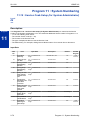
11-10 : Service Code Setup (for System Administrator).................................. 2-70
11-11 : Service Code Setup (for Setup/Entry Operation)................................. 2-73
11-12 : Service Code Setup (for Service Access)............................................ 2-77
11-13 : Service Code Setup (for ACD)............................................................. 2-81
11-14 : Service Code Setup (for Hotel)............................................................ 2-83
11-15 : Service Code Setup, Administrative (for Special Access)................... 2-85
11-16 : Single Digit Service Code Setup.......................................................... 2-87
11-17 : ACD Group Pilot Number..................................................................... 2-88
11-19 : Remote Conference Pilot Number Setup............................................. 2-89
11-20 : Dial Extension Analyze Table.............................................................. 2-90
Program 12 : Night Mode Setup................................................................................ 2-91
12-01 : Night Mode Function Setup................................................................. 2-91
12-02 : Automatic Night Service Patterns........................................................ 2-92
12-03 : Weekly Night Service Switching.......................................................... 2-94
12-04 : Holiday Night Service Switching.......................................................... 2-95
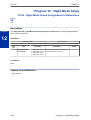
12-05 : Night Mode Group Assignment for Extensions.................................... 2-96
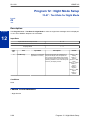
12-06 : Night Mode Group Assignment for Trunks........................................... 2-97
12-07 : Text Data for Night Mode..................................................................... 2-98
12-08 : Night Mode Service Range.................................................................. 2-99
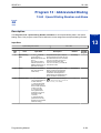
Program 13 : Abbreviated Dialing............................................................................ 2-100
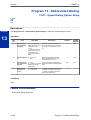
13-01 : Speed Dialing Option Setup............................................................... 2-100
13-02 : Group Speed Dialing Bins.................................................................. 2-101
13-03 : Speed Dialing Group Assignment for Extensions.............................. 2-102
13-04 : Speed Dialing Number and Name..................................................... 2-103
13-05 : Speed Dial Trunk Group.................................................................... 2-105
13-06 : Speed Dial Number and Name.......................................................... 2-106
13-11 : Abbreviated Dial Group Name........................................................... 2-107
Program 14 : Trunk, Basic Setup............................................................................. 2-108
14-01 : Basic Trunk Data Setup..................................................................... 2-108
14-02 : Analog Trunk Data Setup................................................................... 2-112
14-04 : Behind PBX Setup............................................................................. 2-115
14-05 : Trunk Group....................................................................................... 2-116
14-06 : Trunk Group Routing......................................................................... 2-117
14-07 : Trunk Access Map Setup................................................................... 2-119
14-08 : Music on Hold Source for Trunks....................................................... 2-121
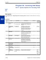
14-09 : Conversation Recording Destination for Trunks................................ 2-122
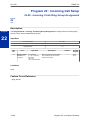
14-11 : ID Setup for IP Trunk......................................................................... 2-123
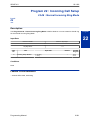
14-12 : SIP Register ID Setup for IP Trunk.................................................... 2-124
Program 15 : Extension, Basic Setup...................................................................... 2-125
15-01 : Basic Extension Data Setup.............................................................. 2-125
15-02 : Multiline Telephone Basic Data Setup............................................... 2-127
ii
Programming Manual
ISSUE 4.0
SL1100
15-03 : Single Line Telephone Basic Data Setup.......................................... 2-133
15-05 : IP Telephone Terminal Basic Data Setup.......................................... 2-136
15-06 : Trunk Access Map for Extensions..................................................... 2-139
15-07 : Programmable Function Keys............................................................ 2-140
15-08 : Incoming Virtual Extension Ring Tone Setup.................................... 2-147
15-09 : Virtual Extension Ring Assignment.................................................... 2-149
15-10 : Incoming Virtual Extension Ring Tone Order Setup.......................... 2-150
15-11 : Virtual Extension Delayed Ring Assignment...................................... 2-151
15-12 : Conversation Recording Destination for Extensions.......................... 2-152
15-13 : Loop Keys.......................................................................................... 2-153
15-14 : Programmable One-Touch Keys ...................................................... 2-154
15-16 : SIP Register ID Setup for Extension.................................................. 2-155
15-17 : CO Message Waiting Indication......................................................... 2-156
15-18 : Virtual Extension Key Enhanced Options.......................................... 2-157
15-22 : Mobile Extension Setup..................................................................... 2-159
15-24 : Registration of Standard SIP Terminal.............................................. 2-160
15-28 : Trunk Incoming Ring Tone of Extension Setup................................. 2-161
Program 16 : Department Group Setup................................................................... 2-162
16-01 : Department Group Basic Data Setup................................................ 2-162
16-02 : Department Group Assignment for Extensions.................................. 2-164
16-03 : Secondary Department Group........................................................... 2-165
16-04 : Call Restriction Between Department Groups................................... 2-166
Program 20 : System Option Setup......................................................................... 2-167
20-01 : System Options.................................................................................. 2-167
20-02 : System Options for Multiline Telephones.......................................... 2-169
20-03 : System Options for Single Line Telephones...................................... 2-172
20-04 : System Options for Virtual Extensions............................................... 2-174
20-06 : Class of Service for Extensions......................................................... 2-175
20-07 : Class of Service Options (Administrator Level)................................. 2-176
20-08 : Class of Service Options (Outgoing Call Service)............................. 2-178
20-09 : Class of Service Options (Incoming Call Service)............................. 2-180
20-10 : Class of Service Options (Answer Service)....................................... 2-182
20-11 : Class of Service Options (Hold/Transfer Service)............................. 2-184
20-12 : Class of Service Options (Charging Cost Service)............................ 2-186
20-13 : Class of Service Options (Supplementary Service)........................... 2-187
20-14 : Class of Service Options for DISA/E&M............................................ 2-191
20-15 : Ring Cycle Setup............................................................................... 2-193
20-16 : Selectable Display Messages............................................................ 2-195
20-17 : Operator Extension............................................................................ 2-197
20-18 : Service Tone Timers.......................................................................... 2-198
20-19 : System Options for Caller ID............................................................. 2-199
20-20 : Message Setup for Non-Caller ID Data............................................. 2-200
20-21 : System Options for Long Conversation............................................. 2-201
20-23 : System Options for CTI...................................................................... 2-202
20-25 : ISDN Options..................................................................................... 2-203
20-26 : Multiplier for Charging Cost............................................................... 2-205
20-28 : Trunk to Trunk Conversation............................................................. 2-206
20-29 : Timer Class for Extension.................................................................. 2-207
20-30 : Timer Class for Trunks....................................................................... 2-208
20-31 : Timer Class Timer Assignment.......................................................... 2-209
20-34 : Remote Conference Group Setup..................................................... 2-212
20-35 : Extension's Operator Setting............................................................. 2-213
20-36 : Trunk's Operator Setting.................................................................... 2-214
20-37 : Operator Extension Group Setup....................................................... 2-215
Programming Manual
iii
SL1100
ISSUE 4.0
20-38 : Operator Group Setting...................................................................... 2-216
20-42 : Night Mode for each package............................................................ 2-217
20-43 : Power supply for each package......................................................... 2-218
20-44 : Watch Mode Setup............................................................................ 2-219
20-45 : Remote Watch Setup......................................................................... 2-220
20-46 : Security Sensor Setup....................................................................... 2-221
20-47 : Time pattern setting for Watch Mode................................................. 2-222
20-48 : Time pattern setting for Security Sensor............................................ 2-223
20-49 : Caller ID Shared Group Basic Data Setup......................................... 2-224
20-55 : Delay Timer for Security Sensor........................................................ 2-225
Program 21 : Outgoing Call Setup........................................................................... 2-226
21-01 : System Options for Outgoing Calls.................................................... 2-226
21-02 : Trunk Group Routing for Extensions.................................................. 2-229
21-03 : Trunk Group Routing for Trunks........................................................ 2-230
21-04 : Toll Restriction Class for Extensions................................................. 2-231
21-05 : Toll Restriction Class......................................................................... 2-232
21-06 : Toll Restriction Table Data Setup...................................................... 2-234
21-07 : Toll Restriction Override Password Setup......................................... 2-236
21-08 : Repeat Dial Setup.............................................................................. 2-237
21-09 : Dial Block Setup................................................................................. 2-238
21-10 : Dial Block Restriction Class Per Extension........................................ 2-239
21-11 : Extension Ringdown (Hotline) Assignment........................................ 2-240
21-12 : ISDN Calling Party Number Setup for Trunks.................................... 2-241
21-13 : ISDN Calling Party Number Setup for Extensions............................. 2-242
21-14 : Walking Toll Restriction Password Setup.......................................... 2-243
21-15 : Individual Trunk Group Routing for Extensions................................. 2-244
21-16 : Trunk Group Routing for Networking................................................. 2-245
21-17 : IP Trunk (SIP) Calling Party Number Setup for Trunk....................... 2-246
21-19 : IP Trunk (SIP) Calling Party Number Setup for Extension................. 2-247
21-20 : SIP Trunk Call Discernment Setup for Extension.............................. 2-248
21-21 : Toll Restriction for Trunks (Seized Trunk Basis Setting)................... 2-249
21-22 : CO Message Waiting Indication - Call Back Settings........................ 2-250
21-26 : Home NPA Setup............................................................................... 2-251
21-27 : HNPA Exceptions Setup.................................................................... 2-252
21-28 : Foreign NPA Locals Setup................................................................. 2-253
Program 22 : Incoming Call Setup........................................................................... 2-254
22-01 : System Options for Incoming Calls.................................................... 2-254
22-02 : Incoming Call Trunk Setup................................................................. 2-256
22-03 : Trunk Ring Tone Range..................................................................... 2-257
22-04 : Incoming Extension Ring Group Assignment.................................... 2-259
22-05 : Incoming Trunk Ring Group Assignment........................................... 2-260
22-06 : Normal Incoming Ring Mode............................................................. 2-261
22-07 : DIL Assignment.................................................................................. 2-262
22-08 : DIL/IRG No Answer Destination........................................................ 2-263
22-09 : DID Basic Data Setup........................................................................ 2-264
22-10 : DID Translation Table Setup.............................................................. 2-266
22-11 : DID Translation Number Conversion................................................. 2-267
22-12 : DID Intercept Ring Group.................................................................. 2-270
22-13 : DID Trunk Group to Translation Table Assignment........................... 2-271
22-14 : VRS Delayed Message for IRG......................................................... 2-272
22-15 : VRS Delayed Message for Department Group.................................. 2-273
22-16 : Private Call Refuse Target Area Setup.............................................. 2-274
22-17 : Dial-In Conversion Table Area Setup for Time Pattern...................... 2-275
22-18 : Private Call Assignment Setup.......................................................... 2-276
iv
Programming Manual
ISSUE 4.0
SL1100
22-20 : Flexible Ringing by Caller ID Setup................................................... 2-277
Program 23 : Answer Features Setup..................................................................... 2-278
23-02 : Call Pickup Groups............................................................................ 2-278
23-03 : Universal Answer/Auto Answer.......................................................... 2-279
23-04 : Ringing Line Preference for Virtual Extensions................................. 2-280
Program 24 : Hold/Transfer Setup........................................................................... 2-281
24-01 : System Options for Hold.................................................................... 2-281
24-02 : System Options for Transfer.............................................................. 2-282
24-03 : Park Group......................................................................................... 2-284
24-04 : Automatic Trunk-to-Trunk Transfer Target Setup.............................. 2-285
24-05 : Department Group Transfer Target Setup......................................... 2-286
24-09 : Call Forward Split Settings................................................................. 2-287
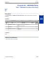
Program 25 : VRS/DISA Setup................................................................................ 2-289
25-01 : VRS/DISA Line Basic Data Setup...................................................... 2-289
25-02 : DID/DISA VRS Message................................................................... 2-290
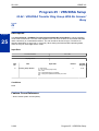
25-03 : VRS/DISA Transfer Ring Group With Incorrect Dialing..................... 2-291
25-04 : VRS/DISA Transfer Ring Group With No Answer/Busy..................... 2-292
25-05 : VRS/DISA Error Message Assignment.............................................. 2-293
25-06 : VRS/DISA One-Digit Code Attendant Setup...................................... 2-294
25-07 : System Timers for VRS/DISA............................................................ 2-296
25-08 : DISA User ID Setup........................................................................... 2-298
25-09 : Class of Service for DISA Users........................................................ 2-299
25-10 : Trunk Group Routing for DISA........................................................... 2-300
25-11 : DISA Toll Restriction Class................................................................ 2-301
25-12 : Alternate Trunk Group Routing for DISA........................................... 2-302
25-13 : System Option for DISA..................................................................... 2-303
25-15 : DISA Transfer Target Setup.............................................................. 2-304
Program 26 : ARS Service....................................................................................... 2-305
26-01 : Automatic Route Selection (ARS/F-Route) Service........................... 2-305
26-02 : Dial Analysis Table for ARS............................................................... 2-306
26-03 : ARS Dial Treatments......................................................................... 2-307
26-04 : ARS Class of Service......................................................................... 2-308
26-11 : Transit Network ID Table................................................................... 2-309
26-12 : Network Specific Parameter Table for ARS....................................... 2-310
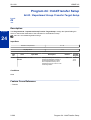
Program 30 : DSS/DLS Console Setup................................................................... 2-311
30-01 : DSS Console Operating Mode........................................................... 2-311
30-02 : DSS Console Extension Assignment................................................. 2-312
30-03 : DSS Console Key Assignment.......................................................... 2-313
30-04 : DSS Console Alternate Answer......................................................... 2-318
30-05 : DSS Console Lamp Table................................................................. 2-319
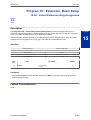
Program 31 : Paging Setup..................................................................................... 2-321
31-01 : System Options for Internal/External Paging..................................... 2-321
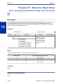
31-02 : Internal Paging Group Assignment.................................................... 2-323
31-03 : Internal Paging Group Settings.......................................................... 2-324
31-04 : External Paging Zone Group............................................................. 2-326
31-05 : Universal Night Answer/Ring Over Page........................................... 2-327
31-06 : External Speaker Control................................................................... 2-328
31-07 : Combined Paging Assignments......................................................... 2-329
31-08 : BGM on External Paging................................................................... 2-330
31-10 : External Paging Group Basic Setting................................................. 2-331
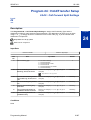
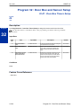
Program 32 : Door Box and Sensor Setup.............................................................. 2-332
32-01 : Door Box Timers Setup...................................................................... 2-332
32-02 : Door Box Ring Assignment................................................................ 2-333
32-03 : Door Box Basic Setup........................................................................ 2-334
Programming Manual
v
SL1100
ISSUE 4.0
32-04 : Door Box Name Setup....................................................................... 2-335
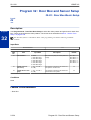
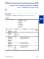
Program 34 : Tie Line Setup.................................................................................... 2-336
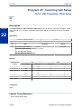
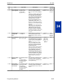
34-01 : E&M Tie Line Basic Setup................................................................. 2-336
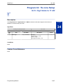
34-02 : E&M Tie Line Class of Service.......................................................... 2-337
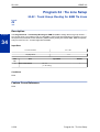
34-03 : Trunk Group Routing for E&M Tie Lines............................................ 2-338
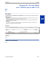
34-04 : E&M Tie Line Toll Restriction Class................................................... 2-339
34-05 : Tie Line Outgoing Call Restriction..................................................... 2-340
34-06 : Add/Delete Digit for E&M Tie Line..................................................... 2-341
34-07 : E&M Tie Line Timer........................................................................... 2-342
34-08 : Toll Restriction Data for E&M Tie Lines............................................. 2-343
34-09 : ANI/DNIS Service Options................................................................. 2-344
34-10 : Digit Delete for T1 ANI....................................................................... 2-347
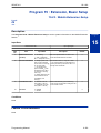
Program 35 : SMDR Account Code Setup.............................................................. 2-348
35-01 : SMDR Options................................................................................... 2-348
35-02 : SMDR Output Options....................................................................... 2-350
35-03 : SMDR Port Assignment for Trunk Group........................................... 2-353
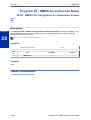
35-04 : SMDR Port Assignment for Department Groups............................... 2-354
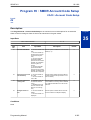
35-05 : Account Code Setup.......................................................................... 2-355
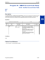
35-06 : Verified Account Code Table............................................................. 2-357
Program 40 : Voice Recording System.................................................................... 2-358
40-01 : Voice Mail Basic Setup...................................................................... 2-358
40-07 : Voice Prompt Language Assignment for VRS................................... 2-359
40-10 : Voice Announcement Service Option................................................ 2-360
40-11 : Preamble Message Assignment........................................................ 2-362
Program 41 : ACD Setup......................................................................................... 2-363
41-01 : System Options for ACD.................................................................... 2-363
41-02 : ACD Group and Agent Assignments................................................. 2-364
41-03 : Incoming Ring Group Assignment for ACD Group............................ 2-365
41-05 : ACD Agent Work Schedules.............................................................. 2-366
41-06 : Trunk Work Schedules....................................................................... 2-367
41-07 : ACD Weekly Schedule Setup............................................................ 2-368
41-08 : ACD Overflow Options....................................................................... 2-369
41-09 : ACD Overflow Table Setting.............................................................. 2-371
41-11 : VRS Delay Announcement................................................................ 2-372
41-12 : Night Announcement Setup............................................................... 2-374
41-13 : VRS Message Number for Night Announcement.............................. 2-375
41-14 : ACD Options Setup............................................................................ 2-376
41-16 : ACD Threshold Overflow................................................................... 2-378
41-19 : ACD Voice Mail Delay Announcement.............................................. 2-379
41-20 : ACD Queue Display Settings............................................................. 2-380
Program 42 : Hotel Setup........................................................................................ 2-381
42-01 : System Options for Hotel/Motel......................................................... 2-381
42-02 : Hotel/Motel Telephone Setup............................................................ 2-382
42-03 : Class of Service Options (Hotel/Motel).............................................. 2-383
42-04 : Hotel Mode One-Digit Service Codes................................................ 2-385
42-05 : Hotel Room Status Printer................................................................. 2-386
42-09 : Flexible Setup for Room Status......................................................... 2-387
Program 44 : ARS/F-Route Setup........................................................................... 2-388
44-01 : System Options for ARS/F-Route...................................................... 2-388
44-02 : Dial Analysis Table for ARS/F-Route Access.................................... 2-389
44-03 : Dial Analysis Extension Table............................................................ 2-391
44-04 : ARS/F-Route Selection for Time Schedule........................................ 2-393
44-05 : ARS/F-Route Table............................................................................ 2-394
44-06 : Additional Dial Table.......................................................................... 2-396
vi
Programming Manual
ISSUE 4.0
SL1100
44-07 : Gain Table for ARS/F-Route Access................................................. 2-397
44-08 : Time Schedule for ARS/F-Route....................................................... 2-398
44-09 : Weekly Schedule for ARS/F-Route.................................................... 2-400
44-10 : Holiday Schedule for ARS/F-Route................................................... 2-401
Program 45 : Voice Mail Integration........................................................................ 2-402
45-01 : Voice Mail Integration Options........................................................... 2-402
45-02 : NSL Option Setup.............................................................................. 2-404
45-04 : Voice Mail Digit Add Assignment....................................................... 2-405
45-05 : Voice Mail Send Protocol Signal Without Additional Digits................ 2-406
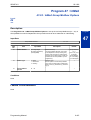
Program 47 : InMail................................................................................................. 2-407
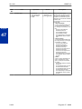
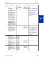
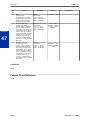
47-01 : InMail System Options....................................................................... 2-407
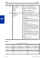
47-02 : InMail Station Mailbox Options.......................................................... 2-411
47-03 : InMail Group Mailbox Options............................................................ 2-415
47-06 : Group Mailbox Subscriber Options.................................................... 2-416
47-07 : InMail Routing Mailbox Options......................................................... 2-420
47-08 : Call Routing Mailbox Options............................................................. 2-422
47-09 : Announcement Mailbox Options........................................................ 2-424
47-10 : InMail Trunk Options.......................................................................... 2-426
47-11 : InMail Answer Table Options............................................................. 2-428
47-12 : InMail Answer Schedules................................................................... 2-431
47-13 : InMail Dial Action Tables................................................................... 2-435
47-15 : Routing Directory Mailbox Options.................................................... 2-438
47-17 : Routing Distribution Mailbox Options................................................. 2-439
47-18 : SMTP Setup....................................................................................... 2-440
47-19 : POP3 Setup....................................................................................... 2-441
47-20 : Station Mailbox Message Notification Options................................... 2-442
47-21 : Station Mailbox Find-Me Follow-Me Options..................................... 2-444
47-22 : Group Mailbox Message Notification Options.................................... 2-445
47-23 : Group Mailbox Find-Me Follow-Me Options...................................... 2-447
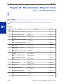
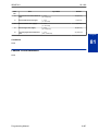
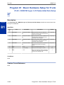
Program 80 : Basic Hardware Setup for System..................................................... 2-448
80-01 : Service Tone Setup........................................................................... 2-448
80-02 : DTMF Tone Setup............................................................................. 2-453
80-03 : DTMF Tone Receiver Setup.............................................................. 2-454
80-04 : Call Progress Tone Detector Setup................................................... 2-456
80-05 : Date Format for SMDR and System.................................................. 2-458
80-07 : Call Progress Tone Detector Frequency Setup................................. 2-459
80-08 : MFC Tone Setup................................................................................ 2-460
80-09 : Short Ring Setup................................................................................ 2-461
80-10 : MF Tone Receiver Setup................................................................... 2-463
80-12 : Caller ID Receiver Setup................................................................... 2-465
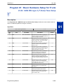
Program 81 : Basic Hardware Setup for Trunk........................................................ 2-466
81-01 : CO Initial Data Setup......................................................................... 2-466
81-05 : ISDN PRI Layer 2 (T-Point) Initial Data Setup................................... 2-468
81-06 : ISDN PRI Layer 3 (T-Point) Timer Setup........................................... 2-469
81-07 : CODEC Filter Setup for Analog Trunk Port....................................... 2-471
81-08 : T1 Trunk Timer Setup........................................................................ 2-472
81-09 : COT CODEC (QSLAC) Filter Setting................................................. 2-475
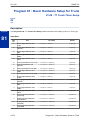
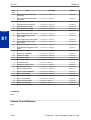
Program 82 : Basic Hardware Setup for Extension................................................. 2-477
82-01 : Incoming Ring Tone........................................................................... 2-477
82-04 : ASTU Initial Data Setup..................................................................... 2-479
82-05 : ISDN PRI Layer2 (S-Point) Initial Data Setup.................................... 2-480
82-06 : ISDN PRI Layer3 (S-point) Timer Setup............................................ 2-481
82-07 : CODEC Filter Setup for Analog Station Port..................................... 2-483
82-08 : Sidetone Volume Setup .................................................................... 2-484
Programming Manual
vii
SL1100
ISSUE 4.0
82-09 : SLIU CODEC Filter Data Setup......................................................... 2-485
82-11 : SLIU Initial Data Setup....................................................................... 2-488
82-12 : OPX Initial Data Setup....................................................................... 2-489
82-14 : Handset/Headset Gain Setup for Multi Line Telephone..................... 2-490
82-21 : Sensor Setup..................................................................................... 2-491
Program 84 : Hardware Setup for VoIPDB.............................................................. 2-492
84-02 : H.225 and H.245 Information Basic Setup......................................... 2-492
84-07 : Firmware Download Setup................................................................. 2-494
84-09 : VLAN Setup....................................................................................... 2-495
84-10 : ToS Setup.......................................................................................... 2-496
84-12 : Networking CODEC Information Basic Setup ................................... 2-497
84-13 : SIP Trunk CODEC Information Basic Setup...................................... 2-499
84-14 : SIP Trunk Basic Information Setup.................................................... 2-503
84-15 : SIP Phone Keep Alive Setup............................................................. 2-505
84-16 : VoIPDB Limiter Control Gain Setup................................................... 2-506
84-19 : SIP Extension CODEC Information Basic Setup............................... 2-508
84-20 : SIP Extension Basic Information Setup............................................. 2-511
84-22 : DR700 Multiline Logon Information Setup......................................... 2-512
84-23 : DR700 Multiline Basic Information Setup.......................................... 2-513
84-24 : DR700 Multiline CODEC Basic Information Setup............................ 2-515
84-26 : VoIP Basic Setup (DSP).................................................................... 2-518
84-27 : VoIP Basic Setup............................................................................... 2-519
84-28 : DR700 Multiline Firmware Name Setup............................................. 2-521
84-29 : SIP-MLT CODEC Information Fixed Mode Setup.............................. 2-522
84-31 : VoIPDB Echo Canceller Setup.......................................................... 2-523
84-32 : FAX Over IP CODEC Setup.............................................................. 2-527
84-39 : SIP Trunk message customize.......................................................... 2-528
Program 90 : Maintenance Program........................................................................ 2-529
90-01 : Installation Date................................................................................. 2-529
90-02 : Programming Password Setup.......................................................... 2-530
90-03 : Save Data.......................................................................................... 2-532
90-04 : Load Data.......................................................................................... 2-533
90-05 : Slot Control........................................................................................ 2-534
90-06 : Trunk Control..................................................................................... 2-535
90-07 : Station Control................................................................................... 2-536
90-08 : System Reset..................................................................................... 2-537
90-09 : Automatic System Reset Time Setup................................................ 2-538
90-10 : System Alarm Setup.......................................................................... 2-539
90-11 : Alarm Report SMTP Setting............................................................... 2-546
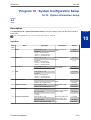
90-12 : System Alarm Output......................................................................... 2-548
90-13 : System Information Output................................................................ 2-549
90-16 : Main Software Information................................................................. 2-550
90-17 : Firmware Information......................................................................... 2-551
90-19 : Dial Block Release............................................................................. 2-552
90-20 : Traffic Report Data Setup.................................................................. 2-553
90-21 : Traffic Report Output......................................................................... 2-555
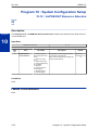
90-23 : Deleting Registration of IP Telephones............................................. 2-556
90-24 : System Alarm Report Notification Time Setup................................... 2-557
90-25 : System Alarm Report CC Mail Setup................................................. 2-558
90-26 : Program Access Level Setup............................................................. 2-559
90-28 : User Programming Password Setup.................................................. 2-560
90-31 : DIM Access over Ethernet................................................................. 2-561
90-33 : Preselected Data Setup..................................................................... 2-562
90-34 : Firmware Information......................................................................... 2-579
viii
Programming Manual
ISSUE 4.0
SL1100
90-35 : Wizard Programming Level Setup..................................................... 2-580
90-36 : Firmware Update Time Setting.......................................................... 2-581
90-37 : Set Temporary License...................................................................... 2-583
90-38 : User Programming Data Level Setup................................................ 2-584
90-39 : Virtual Loop Back Port Reset............................................................. 2-586
90-41 : Server Setting to Update Terminal Local Data.................................. 2-587
90-42 : DR700 Multiline Terminal Version Information.................................. 2-588
90-43 : Deleting Terminal License of DR700................................................. 2-589
90-44 : Deleting Terminal License of TCP Interface...................................... 2-590
90-45 : Temporary Password Change for Multiline Telephone...................... 2-591
90-50 : System Alarm Display Setup............................................................. 2-592
90-51 : Alarm Setup for Maintenance Exchange........................................... 2-593
90-52 : System Alarm Save........................................................................... 2-594
90-53 : System Alarm Clear........................................................................... 2-595
90-54 : PC/Web Programming....................................................................... 2-596
90-55 : Free License Select........................................................................... 2-597
90-56 : NTP Setup......................................................................................... 2-598
90-57 : Backup Recovery Data...................................................................... 2-599
90-58 : Restore Recovery Data...................................................................... 2-600
90-59 : Delete Recovery Data........................................................................ 2-601
90-60 : T1/ISDN Layer Status Information..................................................... 2-602
90-62 : Security ID Information ..................................................................... 2-603
90-63 : DR700 Control................................................................................... 2-604
90-65 : 1st Party CTI Authentication Password Setup................................... 2-605
90-66 : FTP Firmware Update setup.............................................................. 2-606
90-67 : Backup Data Auto-save Interval Time Set......................................... 2-607
90-68 : Side Tone Auto Setup........................................................................ 2-608
Program 92 : Copy Program.................................................................................... 2-609
92-01 : Copy Program.................................................................................... 2-609
92-02 : Delete All Extension Numbers........................................................... 2-612
92-03 : Copy Program by Port Number.......................................................... 2-613
92-04 : Extension Data Swap......................................................................... 2-614
92-05 : Extension Data Swap Password........................................................ 2-616
92-06 : Fill Command..................................................................................... 2-617
92-07 : Delete Command............................................................................... 2-618
Program 93 : System Information............................................................................ 2-619
93-01 : Day/Night Mode Information.............................................................. 2-619
93-02 : Trunk Information............................................................................... 2-620
93-03 : Extension Information........................................................................ 2-621
93-04 : Redial List.......................................................................................... 2-623
93-05 : Department Group Information.......................................................... 2-624
Programming Manual
ix
SL1100
ISSUE 4.0
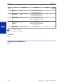
LIST OF TABLES
Table 1-1
Table 1-2
Table 1-3
Table 1-4
Table 2-1
Table 2-2
Table 2-3
Table 2-4
Table 2-5
Table 2-6
Table 2-7
Table 2-8
Table 2-9
Table 2-10
Table 2-11
Table 2-12
Table 2-13
Table 2-14
Table 2-15
Table 2-16
Table 2-17
Table 2-18
x
Keys for Entering Data....................................................................................... 1-3
Keys for Entering Names................................................................................... 1-4
Softkey Display Prompts.................................................................................... 1-5
System Number Plan/Capacities....................................................................... 1-5
System Numbering Default Settings................................................................ 2-59
Function Number List .................................................................................... 2-141
Function Number List .................................................................................... 2-144
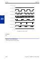
Program 15-08 - Incoming Signal Frequency Patterns.................................. 2-147
Ringing Cycles .............................................................................................. 2-193
Program 22-03 - Incoming Signal Frequency Patterns ................................. 2-257
Function Number List..................................................................................... 2-313
Function Number List..................................................................................... 2-317
47-02-16 Default Table.................................................................................. 2-414
47-06-14 Default Table................................................................................ 2-419
47-07-03 Default Table................................................................................ 2-421
47-10-03 Default Table................................................................................ 2-427
Basic Tones................................................................................................. 2-448
Frequency 1/2 Table.................................................................................... 2-461
Ring Cycle Table......................................................................................... 2-462
Default Table............................................................................................... 2-462
82-01 Default Table..................................................................................... 2-478
Description of Alarm.................................................................................... 2-539
Programming Manual
Introduction
1
SECTION 1 BEFORE YOU START PROGRAMMING
Before customizing your system be sure to read this chapter first.
This Manual is created for System : SL1100
SECTION 2 HOW TO USE THIS MANUAL
This section lists each program in numerical order. For example, Program 10-01 is at the beginning of
the section and Program 92-01 is at the end. The information on each program is subdivided into the
following headings :
Description describes what the program options control. The Default Settings for each program are
also included. When you first install the system, it uses the Default Setting for all programs. Along with
the Description are the Conditions which describe any limits or special considerations that may apply
to the program.
The program access level is just above the Description heading. You can only use the program if your
access level meets or exceeds the level the program requires. Refer to How to Enter Programming
Mode on page 1-2 for a list of the system access levels and passwords.
Feature Cross Reference provides you with a table of all the features affected by the program. You
will want to keep the referenced features in mind when you change a program. Customizing a feature
may have an effect on another feature that you did not intend.
Telephone Programming Instructions shows how to enter the program data into system memory.
For example :
1. Enter the programming mode.
2. 15-07-01
15-07-01
TEL
KY01 = *01
+
tells you to enter the programming mode, dial 150701 from the telephone dial pad. After you do, you
will see the message “15-07-01 TEL” on the first line of the telephone display. This indicates the
program number (15-07), item number (01), and that the options are being set for the extension. The
second row of the display “KY01 = *01” indicates that Key 01 is being programmed with the entry of
*01. The third row allows you to move the cursor to the left or right, depending on which arrow is
Programming Manual
1-1
Introduction
This chapter provides you with detailed information about the system programs. By changing a
program, you change the way the feature associated with that program works. In this chapter, you find
out about each program, the features that the program affects and how to enter the program data into
system memory.
ISSUE 4.0
SL1100
pressed. To learn how to enter the programming mode, refer to How to Enter Programming Mode on
page 1-2.
SECTION 3 HOW TO ENTER PROGRAMMING MODE
To enter programming mode :
1.
Go to any working display telephone.
In a newly installed system, use extension (port 1).
2.
3.
4.
Do not lift the handset.
Press Speaker.
# * # *.
5.
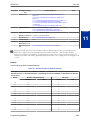
Dial the system password + Hold.
Refer to the following table for the default system passwords. To change the passwords, use
90-02 : Programming Password Setup on page 2-530.
Program Mode
Base Service OP1 OP2
Password
User Name
Level
Programs at this Level
******
necam
1 (MF)
Manufacture Level (MF) :
80-02, 80-03, 80-04, 80-05, 80-07, 80-10, 81-04, 81-05, 82-01, 82-04,
82-05, 82-08
12345678
sltech
2 (IN)
Installation (IN) :
All programs in this section not listed for MF, SA, & SB
0000
ADMIN1
3 (SA)
System Administrator - Level 1 (SA) :
10-01, 10-02, 10-12, 10-13, 10-14, 10-15, 10-16, 10-17, 10-18, 10-23,
10-24, 10-25, 10-28, 10-29, 10-45, 12-02, 12-03, 12-04, 12-08, 15-01,
15-07, 15-09, 15-10, 15-11, 20-16, 20-34, 21-07, 21-14, 22-04, 22-11,
22-17, 25-08, 30-03, 30-04, 32-02, 45-02, 84-22, 90-03, 90-04, 90-06,
90-07, 90-19, 90-57, 90-58, 90-59, 90-65
9999
ADMIN2
4 (SB)
System Administrator - Level 2 (SB) :
13-04, 13-05, 13-06, 13-11, 15-14, 21-20
SECTION 4 HOW TO EXIT PROGRAMMING MODE
To-exit the programming mode :
When you are done programming, you must be out of a program option to exit (pressing the Mute key
will exit the program option).
1. Press Mute key to exit the program options, if needed.
Program Mode
Base Service OP1 OP2
2.
1-2
Press Speaker. If changes were to the system programming, "Saving System Data" is displayed.
Introduction
ISSUE 4.0
3.
SL1100
The display shows "Complete Data Save" when completed and exits the telephone to an idle
mode.
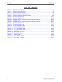
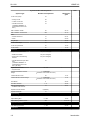
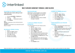
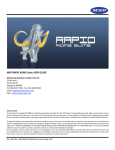
To save a customer’s database, a blank Compact Flash (CF) Card is required. Insert the CF Card into the
CPU and, using Program 90-03, save the software to the CF Card. (Program 90-04 is used to reload the
customer data if necessary.) Note that a CF Card can only hold one customer database. Each database to
be saved requires a separate drive.
CF card
CPU card
CF Slot (CN2)
VMDB-C1
SECTION 5 USING KEYS TO MOVE AROUND IN THE PROGRAMS
Once you enter the programming mode, use the keys in the following chart to enter data, edit data and
move around in the menus.
Table 1-1 Keys for Entering Data
When you want to ...
Telephone Programming
Enter Data into program
0 ~ 9, *, # Line Key (1 ~ 6)
Next Index
Cursor Key (Up)
Prior Index
Cursor Key (Down)
Select Data
Line Key (1 ~ 6)
All Clear
Flash
Register
Hold
Enter
Go Back to Prior Screen
Mute
Clear / Back
Move Cursor Jump Up/Down
DND
Delete single character
Clear / Back
Next Page
Help
Toggle between Number/Character
While in a Entering Number
Prior Page
Transfer
Quit the programming
Speaker
Exit
Move Cursor to Left
Cursor Key (Left)
Soft Key1
Change Program Number
Soft Key2
Change Index Number
Programming Manual
1-3
ISSUE 4.0
SL1100
When you want to ...
Change Program Number
Telephone Programming
Soft Key3
Change Index Number
Move Cursor to Right
Cursor Key (Right)
Soft Key4
SECTION 6 PROGRAMMING NAMES AND TEXT MESSAGES
Several programs (e.g., Program 20-16 : Selectable Display Messages) require you to enter text. Use
the following chart when entering and editing text. When using the keypad digits, press the key once
for the first character, twice for the second character, etc. For example, to enter a C, press the key 2
three times. Press the key six times to display the lower case letter. The name can be up to 12 digits
long.
Table 1-2 Keys for Entering Names
Use this keypad digit ...
When you want to ...
1
Enter characters : 1 @ [ ¥ ] ^ _ ` { | }
2
Enter characters : A-C, a-c, 2.
3
Enter characters : D-F, d-f, 3.
4
Enter characters : G-I, g-i, 4.
5
Enter characters : J-L, j-l, 5.
6
Enter characters : M-O, m-o, 6.
7
Enter characters : P-S, p-s, 7.
8
Enter characters : T-V, t-v, 8.
9
Enter characters : W-Z, w-z, 9.
0
Enter characters : 0 ! “ # $ % & ’ ( ) ô õ ú å ä æ ö ü α ε θ В
*
Enter characters : * + , - . / : ; < = > ? π Σ σ Ω ∞ ¢ £
#
# = Accepts an entry (only required if two letters on the same key are needed - ex : TOM).
Pressing # again = Space. (In system programming mode, use the right arrow Softkey instead to accept and/or add a space.)
Clear/Back
Flash
ÁÀÂÃÅÆÇÉÊìó0
Clear the character entry one character at a time.
Clear all the entries from the point of the flashing cursor and to the right.
SECTION 7 USING SOFTKEYS FOR PROGRAMMING
Each Display telephone with Softkeys provides interactive Softkeys for intuitive feature access. The
options for these keys will automatically change depending on where you are in the system
programming. Simply press the Softkey located below the option you wish and the display will change
accordingly.
_
Program Mode
Base Service OP1 OP2
Pressing the Cursor key Up or Down will scroll between the menus.
1-4
Introduction
ISSUE 4.0
SL1100
_
Program Mode
Hard Mtnance
SECTION 8 WHAT THE SOFTKEY DISPLAY PROMPTS MEAN
When using a display telephone in programming mode, various Softkey options are displayed. These
keys will allow you to easily select, scan, or move through the programs.
Table 1-3 Softkey Display Prompts
Softkey Display Prompts
If you press this Softkey ...
back
The system will ...
Go back one step in the program display.
You can press Cursor Key (UP) or Cursor Key (Down) to scroll forward or backward through a
list of programs.
Scroll down through the available programs.
Scroll up through the available programs.
select
Select the currently displayed program.
Move the cursor to the left.
Move the cursor to the right.
-1
Move back through the available program options.
+1
Move forward through the available program options.
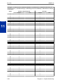
SECTION 9 SYSTEM NUMBER PLAN/CAPACITIES
The following table provides the capacities for the SL1100 system.
Table 1-4 System Number Plan/Capacities
System Number Plan/Capacities
System Type
Number Plan/Capacities
Analog Caller ID Detector (detected by DSP)
96 channels
Note
Related Program
System
Classes of Service
15
20–06
Day/Night Mode Numbers
8
12–07
Day/Night Service Patterns
4
12–07
Dial Tone Detector
DTMF Receiver
96
Toll Restriction Classes
15
Verifiable Account Code Table
800
35–06
Trunk
Trunk Port Number
Programming Manual
84
1-5
SL1100
ISSUE 4.0
System Number Plan/Capacities
System Type
Number Plan/Capacities
Note
Related Program
Trunk Ports (Total) :
76
• Analog Trunks
36
• T1/PRI Trunk Ports
48
• VoIPDB Trunk Ports
(VoIPDB & MEMDB is required. Need license to be
Max.)
16
DID Translation Tables
20
22–10
DID Translation Table Entries
800
22–10
• Classes of Service
• Users
15
15
20–14
25–09
Ring Groups
25
22–04
Trunk Access Maps
84
14–07
Trunk Group Numbers
25
14–05
Trunk Routes
25
14–06
DISA :
Extension
Telephone Extension Ports
112 (V3.5 Changed)
• Multiline Terminals
96 (V3.5 Changed)
• Single Line Phones/Analog
Devices
80 (V3.5 Changed)
• VoIPDB Extensions (SIP-MLT/
Std)
(VoIPDB & MEMDB is required. Need license to be
Max. (SIP-Std))
Digital Extension Ports
• Physical Ports
Telephone Extension Number
Range
Virtual Extension Ports
32
01 ~ 08
1 ~ 89999999*
(*Extension cannot start with 0 or 9)
50
11–04
1 ~ 89999999*
(*Extension cannot start with 0 or 9)
11–04
6
32–02
1~6
32–02
DSS Consoles Numbers :
• 60 Button DSS Console
12
30–01
Operator Access Number
0 (Default)
Virtual Extension Number Range
Door Boxes
Door Box Numbers
Operator Extension
15
Speed Dialing
Speed Dialing Groups
Speed Dialing Bins
Speed Dialing Table-Common
32
13–02
0 ~ 999
13–02
900
13–01–03
1 ~ 100
25–06
Automated Attendant
VRS Message Numbers
Conference
1-6
Introduction
ISSUE 4.0
SL1100
System Number Plan/Capacities
System Type
Conference Circuits
Number Plan/Capacities
Note
Related Program
32 : maximum
(16 Parties Per Conference)
Department and Pickup Groups
Department (Extension) Group
Numbers
1 ~ 32
16–01
Call Pickup Group Numbers
1 ~ 32
23–02
Hotline
Internal Hotline
128
External Hotline
128
Paging and Park
Internal Page Group Numbers
0, 01 ~ 32
31–02
External Page Group Numbers
1~3
31–04
External Speakers
1~3
31–04
Park Group Numbers
1 ~ 64
24–03
Park Orbits
1 ~ 64
24–03
1~2
35–03
SMDR
SMDR Ports
VRS/VM InMail
VRS/VM InMail
1
VRS/VM Ports
(Need license and MEMDB)
16
VRS Port
(Need MEMDB)
16
VRS Attendant Messages
3
VRS Recordable Messages
100
VRS Ports
16
40–10–02
VoIPDB
RTP Ports
0 ~ 65534
RTCP Ports
0 ~ 65535
DSP Resources
16
Passwords
Programming Passwords :
Level 1 (MF)
PCPro/WebPro User Name :
*****
Level 2 (IN)
PCPro/WebPro User Name :
12345678
sltech
Level 3 (SA)
PCPro/WebPro User Name :
0000
ADMIN1
Level 4 (SB)
PCPro/WebPro User Name :
9999
ADMIN2
Programming Password Users
necam
8
Extension numbers can be one to eight digits long. Refer to the Flexible System Numbering feature in the SL1100 Features
and Specifications Manual.
Programming Manual
1-7
SL1100
ISSUE 4.0
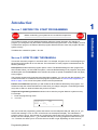
SECTION 10 CONCEPT OF SLOT NUMBER
Each unit installed to the system has a slot number assigned. Some of slot number are fixed to a unit
that be installed. Other slots are not fixed to unit but fixed to location where it is installed. Below chart
shows the slot and its number :
Main KSU
Expansion KSU 1-3
Slot 0 Base Unit
Slot 10 4th Unit*
Slot 3 3rd Unit
Slot 2 2nd Unit
Slot 1 Base Unit
C
P
U
Slot 11/12/- 4th Unit
Slot 6/9/15 3rd Unit
Slot 5/8/14 2nd Unit
Slot 4/7/13 Base Unit
E
X
I
F
E
* Note: Lot D or higher Main KSU or FPGA Version 0100 and V3.5 or higher System Software required.
FPGA version can be found in PC Pro/Web Pro and Lot # is on side of Chassis.
- To verify if your Chassis is D or higher check the lot # (e.g. 118DCA-G). The 4th Character
needs to be D or higher.
- To verify the FPGA version connect with PC Pro/Web Pro and check version information in the
blade configuration screen.
However the maximum trunk port will be limited to 84 ports even though the expansion Trunk card
is fully mounted into the four KSUs.
Please see the hardware manual for further information.
1-8
Introduction
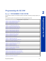
Programming the SL1100
2
SECTION 1 PROGRAMMING YOUR SYSTEM
The information contained in this chapter provides the information necessary to properly program your
system.
Programming the SL1100
The programming blocks are organized into the following programming modes.
Program Number : Program Name
Program 10 : System Configuration Setup on page 2-3
Program 11 : System Numbering on page 2-58
Program 12 : Night Mode Setup on page 2-91
Program 13 : Abbreviated Dialing on page 2-100
Program 14 : Trunk, Basic Setup on page 2-108
Program 15 : Extension, Basic Setup on page 2-125
Program 16 : Department Group Setup on page 2-162
Program 20 : System Option Setup on page 2-167
Program 21 : Outgoing Call Setup on page 2-226
Program 22 : Incoming Call Setup on page 2-254
Program 23 : Answer Features Setup on page 2-278
Program 24 : Hold/Transfer Setup on page 2-281
Program 25 : VRS/DISA Setup on page 2-289
Program 26 : ARS Service on page 2-305
Program 30 : DSS/DLS Console Setup on page 2-311
Program 31 : Paging Setup on page 2-321
Program 32 : Door Box and Sensor Setup on page 2-332
Program 34 : Tie Line Setup on page 2-336
Program 35 : SMDR Account Code Setup on page 2-348
Program 40 : Voice Recording System on page 2-358
Program 41 : ACD Setup on page 2-363
Program 42 : Hotel Setup on page 2-381
Program 44 : ARS/F-Route Setup on page 2-388
Program 45 : Voice Mail Integration on page 2-402
Program 47 : InMail on page 2-407
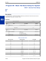
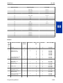
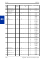
Program 80 : Basic Hardware Setup for System on page 2-448
Program 81 : Basic Hardware Setup for Trunk on page 2-466
Program 82 : Basic Hardware Setup for Extension on page 2-477
Program 84 : Hardware Setup for VoIP on page 2-492
Program 90 : Maintenance Program on page 2-529
Program 92 : Copy Program on page 2-609
Programming Manual
2-1
SL1100
ISSUE 4.0
Program Number : Program Name
Program 93 : System Information on page 2-619
2-2
Programming the SL1100
ISSUE 4.0
SL1100
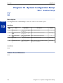
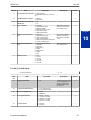
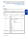
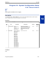
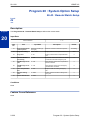
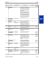
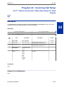
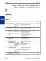
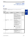
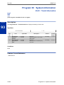
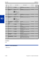
Program 10 : System Configuration Setup
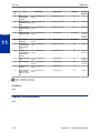
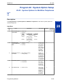
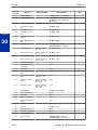
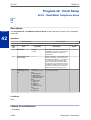
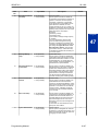
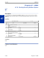
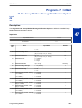
10-01 : Time and Date
Level:
SA
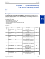
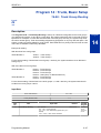
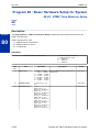
Description
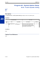
Use Program 10-01 : Time and Date to change the system Time and Date through system
programming. Extension users can also dial Service Code 728 to change the time if allowed by an
extension Class of Service.
Program
10
Input Data
Item
No.
Item
Input Data
Description
Default
01
Year
07 ~ 96
Enter 2 digits for year (07 ~ 96).
No Setting
02
Month
01 ~ 12
Enter 2 digits (01 ~ 12) for the month.
No Setting
03
Day
01 ~ 31
Enter 2 digits (01 ~ 31) for the day.
No Setting
04
Week
1 ~ 7 (Sun ~ Sat)
Enter digit for the day of the week (1 =
Sunday, 7 = Saturday).
No Setting
05
Hour
00 ~ 23
Enter 2 digits for the hour (00 ~ 23).
No Setting
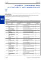
06
Minute
00 ~ 59
Enter 2 digits for the minute (00 ~ 59).
No Setting
07
Second
00 ~ 59
Enter 2 digits for the second (00 ~ 59).
No Setting
Conditions
None
Feature Cross Reference
• Clock/Calendar Display/Time and Date
Programming Manual
2-3
SL1100
ISSUE 4.0
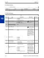
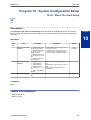
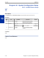
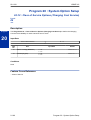
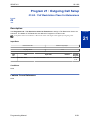
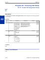
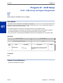
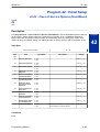
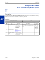
Program 10 : System Configuration Setup
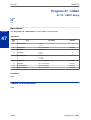
10-02 : Location Setup
Level:
SA
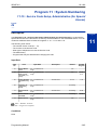
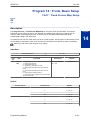
Description
Program
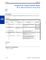
Use Program 10-02 : Location Setup to define the location of the installed system.
10
Input Data
Item
No.
Item
Input Data
Description
Default
01
Country Code
Dial (up to four digits) : Enter the country code.
0 ~ 9, *, #
1
02
International Access
Code
Dial (up to four digits) : Enter the international access code.
0 ~ 9, *, #
03
Other Area Access
Code
Dial (up to two digits) :
0 ~ 9, *, #
Enter the other area access code.
04
Area Code
Dial (up to six digits) :
0 ~ 9, *, #
Enter the local area code.
No Setting
05
Trunk Access Code
Dial (up to eight digits) : 0 ~ 9, *, #
Enter the trunk access code digits required
to place an outgoing call.
No Setting
No Setting
9
Conditions
None
Feature Cross Reference
None
2-4
Program 10 : System Configuration Setup
ISSUE 4.0
SL1100
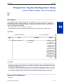
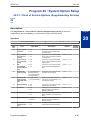
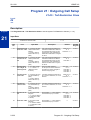
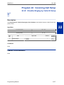
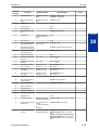
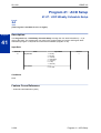
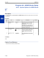
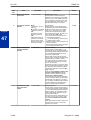
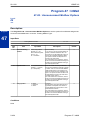
Program 10 : System Configuration Setup
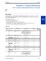
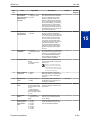
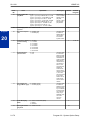
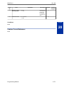
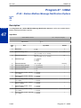
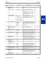
10-03 : ETU Setup
Level:
IN
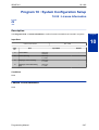
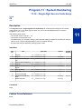
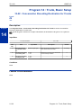
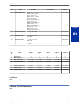
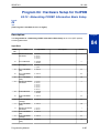
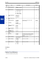
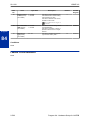
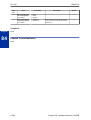
Description
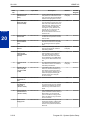
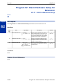
Use Program 10-03 : ETU Setup to setup and confirm the Basic Configuration data for each unit.
When changing a defined terminal type, first set the type to 0 and then plug the new device in to have
the system automatically define it or you may have to reseat the unit.
The items highlighted in gray are read only and cannot be changed.
Input Data
Slot No.
00 ~ 15 (V3.5 Changed)
For ESIU PKG Setup
Physical Port Number
Item
No.
01 ~ 08
Item
Input Data
Description
Default
01
Terminal Type (B1)
0 = No setting
1 = Multi-Line Telephone
10 = DSS Console
0
02
Logical Port Number
0 = No setting
1 = Multi-Line Telephone (1 ~
96 (V3.5 Changed) )
10 = DSS Console (1 ~ 12)
0
10
Bottom option information
0 = None
4 = WHA
0
12
Multi-Line Telephone Line
0 = None
12 = 12 Line
Terminal Type (B1)
24 = 24 Line
0
This program can
only be change by using PC Programming.
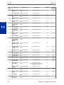
For SLIU PKG Setup
Physical Port Number
Item No.
Item
01 ~ 08
Input Data
Default
01
Logical Port Number
0 ~ 112 (V3.5 Changed)
03
Transmit Gain Level (S-Level)
1 ~ 63 (- 15.5 ~ + 15.5 dB)
32 (0 dB)
04
Receive Gain Level (R-Level)
1 ~ 63 (- 15.5 ~ + 15.5 dB)
32 (0 dB)
05
Select port type
0 = SLT
1 = Door Phone
Programming Manual
0
0
2-5
Program
10
SL1100
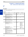
ISSUE 4.0
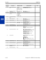
For COIU Unit Setup
Physical Port Number
Item No.
01
1~4
Item
Input Data
Logical Port Number
Default
1 ~ 36
0
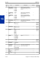
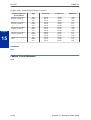
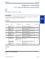
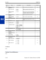
For PRIU PKG Setup
ISDN Line Number
Program
10
Item No.
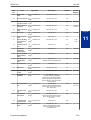
2-6
01 ~ 24
Item
Input Data
Description
Default
01
ISDN Line Mode
0 = No setting
1 = T-Point
2 = S-Point
6 = S-Point (Leased Line)
02
Logical Port Number
[0 : No setting] = 0
[1 : T-Point] = 1 ~ 84
[2 : S-Point] = 1 ~ 84
[6 : S-Point (Leased Line)] = 1 ~ 84
03
CRC Multi-frame (CRC4)
(Only for 2M = 30ch Mode)
0 = off
1 = on
04
Layer 3 Timer Type
1~5
05
CLIP Information
0 = No
1 = Yes
06
Length of Cable
0 = Level 1
1 = Level 2
2 = Level 3
3 = Level 4
4 = Level 5
2
07
S-point DDI digits
0-4
0
08
Dial Sending Mode
0 = Enbloc Sending
1 = Overlap Sending
ISDN Protocol definition
0
09
Dial Information Element
0 = Keypad Facility
1 = Called Party Number
ISDN Protocol definition
Only when Dial Sending
Mode (10-03-08) is set for
1 (Overlap Sending).
0
13
Loss-Of-Signal Detection
Limit
0 = Level 0 (lowest sensitivity)
1 = Level 1
2 = Level 2
3 = Level 3
4 = Level 4
5 = Level 5
6 = Level 6
7 = Level 7 (highest sensitivity)
If the transmit/receive
voltage is less than the
setting in 10-03-13, the
system considers this as
Loss-Of-Signal and the
PRI does not come up.
Note that there are different values based on the
setting in 10-03-12 for the
PRI.
2
1
The start port number of a PRI line is
displayed.
0
1
Each timer value of
Layer 3 is set up for
each type in Program
81-06 (T-Bus)
1
Based on this setting, the
system includes a Presentation Allowed (1) or
Presentation Restricted
(0) in the Setup message
to allow or deny the Calling Party Number. Program 15-01-04 must also
be set to 1 if this option is
enabled.
1
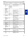
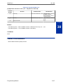
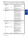
Program 10 : System Configuration Setup
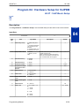
ISSUE 4.0
SL1100
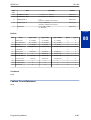
Item No.
Item
14
Service Protocol for S-point
0 = Keypad facility
1 = Specified Protocol for Aspire system
0
15
Call Busy Mode for S-point
0 = Alerting
1 = Disconnect
0
16
Two B-Channel Transfer for
PRI Service
0 = off
1 = on
0
18
Type of Number
0 = Unknown
1 = International number
2 = National number
3 = Network Specific number
4 = Subscriber number
5 = Abbreviated number
ISDN Protocol definition.
Select the number type
for the ISDN circuit.
Numbering Plan Identification
0 = Unknown
1 = ISDN numbering plan
2 = Data numbering plan
3 = Telex numbering plan
4 = National standard numbering plan
5 = Private numbering plan
ISDN Protocol definition.
Select the Numbering
Plan used for the ISDN
circuit.
1
20
Network Exchange Selection
0 = Standard (same as NI-2)
1 = reserved
2 = reserved
3 = DMS (A211)
4 = 5ESS
5 = DMS (A233)
6 = 4ESS
7 = NI-2
Select the ISDN protocol
for the ISDN circuit
7
21
Number of Ports
0 = Auto
1 = 4 Ports
2 = 8 Ports
3 = 12 Ports
4 = 16 Ports
5 = 20 Ports
19
Input Data
Description
Default
2
Program
10
0
For PRI (T1) PKG Setup
Physical Port Number
Item
No.
01 ~ 24
Item
Input Data
Description
Default
The start port number of a
T1 line is displayed, and
24 logic ports are automatically assigned to a
DTI (T1) line.
0
01
Logical Port Number
1 ~ 84
02
T1 Signal Format Selection
0 = D4 (12 Multi Frame)
1 = ESF (24 Multi Frame)
0
03
Zero Code Suppression
0 = B8ZS
1 = AMI/ZCS
0
04
Line Length Selection
0 = 0 feet ~ 133 feet
1 = 133 feet ~ 266 feet
2 = 266 feet ~ 399 feet
3 = 399 feet ~ 533 feet
4 = 533 feet ~ 655 feet
0
05
T1 Clock Source
0 = Internal
1 = External
1
Programming Manual
2-7
SL1100
ISSUE 4.0
Item
No.
06
Item
Input Data
Number of Ports
Description
Default
0 = Auto
1 = 4 Ports
2 = 8 Ports
3 = 12 Ports
4 = 16 Ports
5 = 20 Ports
0
For VoIPDB PKG Setup
Physical Port Number
Program
10
Item No.
01 ~ 32
Item
Input Data
Default
01
Trunk Logical Port Number
1 ~ 84
0
02
Trunk Type
1 = SIP
1
Conditions
• When changing a defined terminal type, first set the type to 0 and then plug the new device in to
have the system automatically define it, or redefine the type manually.
• The system must have a unit installed to view/change the options for that type of unit.
Feature Cross Reference
None
2-8
Program 10 : System Configuration Setup
SL1100
ISSUE 4.0
Program 10 : System Configuration Setup
10-04 : Music On Hold Setup
Level:
IN
Description
Use Program 10-04 : Music on Hold Setup to set the Music on Hold (MOH) source. For internal
Music on Hold, the system can provide a service tone callers on hold or one of eleven synthesized
selections.
Program
10
Input Data
Item
No.
Item
Input Data
Description
01
Music on Hold Source 0 = Internal MOH (Tone • Internal Music Tune - The tune is set by
Selection
set by PRG 10-04-02)
Program 10-04-02.
1 = External MOH (Tone • External Source - ACI input via audio
set by PRG 10-60-01:
connector (J421) (Program10-60-01).
Audio Port No.2)
• Silence - Callers on hold hear silence.
2 = Service Tone (Tone
set by PRG 80-01, tone
64)
3 = VMDB (Tone set by
PRG 10-04-02)
02
Music on Hold Tone
Selection
[In case Item 1 is 0.]
1 = Download File1
2 = Download File2
3 = Download File3
[In case Item 1 is 1, 2, or
3.]
1 ~ 100 = VRS Message
Number
03
Audio Gain Setup
1 ~ 63 (- 15.5 ~ + 15.5
dB)
Download File1 : Farewell Song (by Chopin)
Download File2 : Die Forelle (by F. Schubert)
Download File3 : Plaisir d’amour (by
J.P.E.Martini)
Default
1 (V1.5
Changed)
1
32 (0 dB)
Conditions
None
Feature Cross Reference
• Background Music
• Music on Hold
Programming Manual
2-9
SL1100
ISSUE 4.0
Program 10 : System Configuration Setup
10-08 : Pre-Ringing Setup
Level:
IN
Description
Program
10
Use Program 10-08 : Pre-Ringing Setup to enable or disable pre-ringing for trunk calls. This sets
how a trunk initially rings a telephone. With pre-ringing, a burst of ringing occurs as soon as the trunk
LED flashes. The call then continues ringing with the normal ring cadence cycle. Without pre-ringing,
the call starts ringing only when the normal ring cadence cycle occurs. This may cause a ring delay,
depending on when call detection occurs in reference to the ring cycle.
Input Data
Item
No.
01
Item
Pre-Ringing
Input Data
0 = No
1 = Yes
Default
0
Conditions
• Used with Analog Trunks only.
Feature Cross Reference
• Central Office Calls, Answering
2-10
Program 10 : System Configuration Setup
SL1100
ISSUE 4.0
Program 10 : System Configuration Setup
10-09 : DTMF and Dial Tone Circuit Setup
Level:
IN
Description
Use Program 10-09 : DTMF and Dial Tone Circuit Setup to allocate the circuits on the CPU for
either DTMF receiving or dial tone detection. The CPU has 16 circuits initially, and an additional 16
circuits are added when a VMDB is installed. By Adding EXIFE system can have up to 128 (V3.5 or
higher). These are used as follows:
• Extension: DTMF receiver for single line telephone
• Trunk: DTMF receiver for analog trunks, dial tone & busy tone detection for analog trunks
Input Data
Circuit/Resource Number
Item
No.
01
Item
DTMF Dial Tone Detection
01 ~ 128 (V3.5 Changed)
Input Data
0 = Common Use
1 = Extension Only
2 = Trunk Only
Default
Resource 01 - 128 = 0
(Common) (V3.5
Changed)
Resource 01 - 16 are
Baic resource (only use
Basic Board)
Resource 17 - 32 are
vmdb resource (only
use Basic Board)
Resource 33 - 64 are
EXIFE1 resource (only
use Expansion 1)
Resource 65 - 96 are
EXIFE2 resource (only
use Expansion 2)
Resource 97 - 128 are
EXIFE3 resource (only
use Expansion 3) (V3.5
Added)
Conditions
• CPU has 16 Channel DSP resources (receivers) only for basic CPU Unit. VMDB has additional 16
DSP resources which you can add to CPU. Addition to that EXIFE also each has 32 DSP resource
(receivers) only for expand unit.
• In case of 0 (= Common) is selected, and if 14-02-10 (Caller ID receive ability) is set to “Yes”, DSP
resources are always allocated to analog trunk only, not for analog extension. If 14-02-10 is set to
“No”, the DSP resources can be used for both analog trunk and analog extension commonly.
Feature Cross Reference
• Caller ID
Programming Manual
2-11
Program
10
SL1100
ISSUE 4.0
• Central Office Calls, Placing
• Direct Inward Dialing (DID)
• Direct Inward System Access (DISA)
Program
10
2-12
Program 10 : System Configuration Setup
ISSUE 4.0
SL1100
Program 10 : System Configuration Setup
10-12 : CPU Network Setup
Level:
SA
Description
Use Program 10-12 : CPU Network Setup to setup the IP Address, Subnet-Mask, and Default
Gateway addresses.
Program
Caution!
If any IP Address or NIC settings are changed, the system must be reset for the changes to take affect.
10
Input Data
Item
No.
Item
Input Data
Description
Default
01
IP Address
0.0.0.0 ~
126.255.255.254
128.0.0.1 ~
191.255.255.254
192.0.0.1 ~
223.255.255.254
Set for CPU.
192.168.0.10
02
Subnet Mask
128.0.0.0 | 192.0.0.0 |
224.0.0.0 | 240.0.0.0 |
248.0.0.0 | 252.0.0.0 |
254.0.0.0 | 255.0.0.0 |
255.128.0.0 |
255.192.0.0 |
255.224.0.0 |
255.240.0.0 |
255.248.0.0 |
255.252.0.0 |
255.254.0.0 |
255.255.0.0 |
255.255.128.0 |
255.255.192.0 |
255.255.224.0 |
255.255.240.0 |
255.255.248.0 |
255.255.252.0 |
255.255.254.0 |
255.255.255.0 |
255.255.255.128 |
255.255.255.192 |
255.255.255.224 |
255.255.255.240 |
255.255.255.248 |
255.255.255.252 |
255.255.255.254 |
255.255.255.255 |
The setting of Subnet Mask is invalid when
all Host Addresses are 0.
If the network section is:
0,
127,
128.0,
191.255,
192.0.0,
223.255.255
The setting of Subnet Mask is invalid.
255.255.255.0
03
Default Gateway
0.0.0.0 ~
126.255.255.254
128.0.0.1 ~
191.255.255.254
192.0.0.1 ~
223.255.255.254
Assign the default gateway IP address.
Programming Manual
0.0.0.0
2-13
SL1100
Item
No.
ISSUE 4.0
Item
Input Data
Time Zone
0~24 (0 = -12 Hours and
24 = +12 Hours)
05
NIC Interface
0 = Auto Detect
NIC Auto Negotiate
1 = 100Mbps, Full Du(CPU)
plex
2 = 100Mbps, Half Duplex
3 = 10Mbps, Full Duplex
4 = 10Mbps, Half Duplex
06
Network Address Port 0 = No (Disable)
Translation (NAPT)
1 = Yes (Enable)
Router Setup
If using an external NAPT Router or not.
07
NAPT Router IP Address(Default Gateway [WAN])
0.0.0.0 ~
126.255.255.254
128.0.0.1 ~
191.255.255.254
192.0.0.1 ~
223.255.255.254
Set the IP address on the WAN side of
router.
08
ICMP Redirect
0= NO, Signaling packets will follow the ICMP
redirect message.
1= YES, Signaling packets will NOT follow the
ICMP redirect message.
When receiving ICMP redirect message,
this determines if the IP Routing Table updates automatically or not.
0
09
IP Address
0.0.0.0 ~
126.255.255.254
128.0.0.1 ~
191.255.255.254
192.0.0.1 ~
223.255.255.254
Assign the IP Address for the VoIPDB.
If a VoIPDB is installed in the system it is
recommended to set PRG 10-12-01 to
0.0.0.0 and all connections to the system
will be made through the VoIPDB.
172.16.0.10
2-14
Determine the offset from Greenwich
Mean Time (GMT) time.
Then enter its respective value.
For example,
Eastern Time (US and Canada) has a
GMT offset of -5.
The program data would then be 7
(0 = - 12,
1 = - 11,
2 = - 10,
3 = - 9,
4 = - 8,
5 = - 7,
6 = - 6,
7 = - 5,
:
24 = + 12)
Default
04
Program
10
Description
07
0
0
0.0.0.0
Program 10 : System Configuration Setup
ISSUE 4.0
Item
No.
10
11
SL1100
Item
Subnet Mask
NIC Setup
Input Data
128.0.0.0 | 192.0.0.0 |
224.0.0.0 | 240.0.0.0 |
248.0.0.0 | 252.0.0.0 |
254.0.0.0 | 255.0.0.0 |
255.128.0.0 |
255.192.0.0 |
255.224.0.0 |
255.240.0.0 |
255.248.0.0 |
255.252.0.0 |
255.254.0.0 |
255.255.0.0 |
255.255.128.0 |
255.255.192.0 |
255.255.224.0 |
255.255.240.0 |
255.255.248.0 |
255.255.252.0 |
255.255.254.0 |
255.255.255.0 |
255.255.255.128 |
255.255.255.192 |
255.255.255.224 |
255.255.255.240 |
255.255.255.248 |
255.255.255.252 |
255.255.255.254 |
255.255.255.255 |
Description
Assign the subnet mask for the VoIPDB
card.
0 = Auto Detect
Set for VoIPDB.
1 = 100 Mbps, Full Duplex
3 = 10 Mbps, Full Duplex
5 = 1 Gbps, Full Duplex
Default
255.255.0.0
Program
10
0
Conditions
• The system must be reset for these changes to take affect.
Feature Cross Reference
None
Programming Manual
2-15
SL1100
ISSUE 4.0
Program 10 : System Configuration Setup
10-13 : In-DHCP Server Setup
Level:
SA
Description
Program
Use Program 10-13 : In-DHCP Server Setup to setup the DHCP Server built into the CPU.
10
Input Data
Item
No.
Item
01
DHCP Server Mode
02
Lease Time
Input Data
Description
Default
0 = Disable
1 = Enable
Enable or disable the use of the built-in
DHCP Server. This program cannot be
enabled if PRG10-63-01 is enabled.
0
Days 0 ~ 255
Lease Time of the IP address to a client.
Hour 0 ~ 23
Minutes 0 ~ 59
05
Last DHCP Data
0 = Disable
1 = Enable
Pressing the Hold Key increments to
the next setting data.
If 10–13–01 is enabled, this setting determines if DHCP resource is enabled
or disabled.
0 day
0 hour
30 minutes
1
Conditions
None
Feature Cross Reference
None
2-16
Program 10 : System Configuration Setup
ISSUE 4.0
SL1100
Program 10 : System Configuration Setup
10-14 : Managed Network Setup
Level:
SA
Description
Use Program 10-14 : Managed Network Setup to set up the range of the IP address which the
DHCP Server leases to a client.
Program
Input Data
10
Item
No.
Item
Input Data
Description
Default
Related Program
01
The Range of the IP
address to Lease.
Minimum :
0.0.0.0 ~ 126.255.255.254
128.0.0.1 ~ 191.255.255.254
192.0.0.1 ~ 223.255.255.254
When Maximum has
not been entered, the
maximum value equals
the minimum value.
172.16.0.100
10-13-04
Maximum :
0.0.0.0 ~ 126.255.255.254
128.0.0.1 ~ 191.255.255.254
192.0.0.1 ~ 223.255.255.254
172.16.5.254
Conditions
None
Feature Cross Reference
None
Programming Manual
2-17
SL1100
ISSUE 4.0
Program 10 : System Configuration Setup
10-15 : Client Information Setup
Level:
SA
Description
Program
Use Program 10-15 : Client Information Setup to set up the client information when the DHCP
server needs to assign a fixed IP address to clients.
10
Input Data
Client Number
Item No.
01
Item
1 ~ 16
Input Data
Description
MAC Address
MAC :
00-00-00-00-00-00 ~
FF-FF-FF-FF-FF-FF
IP Address
1.0.0.0 ~
126.255.255.254
128.0.0.1 ~
191.255255.254
192.0.0.1 ~
223.255.255.254
Default
00-00-00-00-00-00
The IP address should be
assigned out of the scope
range set up in Program
10-14.
0.0.0.0
Conditions
None
Feature Cross Reference
None
2-18
Program 10 : System Configuration Setup
ISSUE 4.0
SL1100
Program 10 : System Configuration Setup
10-16 : Option Information Setup
Level:
SA
Description
Use Program 10-16 : Option Information Setup to set up the option given from the DHCP server to
each client.
The items highlighted in gray are read only and cannot be changed.
10
Input Data
Item
No.
01
Item
Router
Input Data
Code number 0 ~ 255
IP address
0.0.0.0 ~ 126.255.255.254
128.0.0.1 ~ 191.255.255.254
192.0.0.1 ~ 223.255.255.254
02
DNS Server
Code number 0 ~ 255
IP address
0.0.0.0 ~ 126.255.255.254
128.0.0.1 ~ 191.255.255.254
192.0.0.1 ~ 223.255.255.254
03
TFTP Server
Code number 0 ~ 255
Maximum 64 character strings
05
06
MGC
Client Host Name
DNS Domain Name
Download Protocol
Set the Router IP address.
3 (Fixed)
Set IP address of DNS
Server.
6 (Fixed)
Set the name for the
TFTP Server.
66 (Fixed)
Code number 0 ~ 255
Code number 0 ~ 255
Set the Client Host
Name.
Set the DNS Domain
Name.
Set Download Protocol
used for AutoConfig (for
DR700 Series).
1 = FTP
2 = HTTP
Encryption Information
Code number 0 ~ 255
Sub code number
Maximum 128 character strings
Programming Manual
0.0.0.0
No setting
172.16.0.10
Sub code number
09
0.0.0.0
IP address
0.0.0.0 ~ 126.255.255.254
128.0.0.1 ~ 191.255.255.254
192.0.0.1 ~ 223.255.255.254
Maximum 20 character strings
08
Default
129 (Fixed)
Maximum 64 character strings
07
Description
Code number 0 ~ 255
Code number 0 ~ 255
Program
12 (Fixed)
No setting
15 (Fixed)
No setting
43 (Fixed)
163 (Fixed)
1
Set an Encryption Information used for AutoConfig (for DR700 series).
43 (Fixed)
164 (Fixed)
No setting
2-19
SL1100
Item
No.
10
ISSUE 4.0
Item
FTP Server Address
Input Data
Code number 0 ~ 255
Sub code number
Description
Default
Set a FTP Server Address used for AutoConfig.
43 (Fixed)
IP address
0.0.0.0 ~ 126.255.255.254
128.0.0.1 ~ 191.255.255.254
192.0.0.1 ~ 223.255.255.254
11
Config File Name
Code number 0 ~ 255
Program
12
Vender Class ID
0.0.0.0
Set a File Name used for
AutoConfig.
Sub code number
10
SNMP Server
POP3 Server
Code number 0 ~ 255
60 (Fixed)
NEC DR700
Code number 0 ~ 255
69 (Fixed)
0.0.0.0
Code number 0 ~ 255
70 (Fixed)
IP address
0.0.0.0 ~ 126.255.255.254
128.0.0.1 ~ 191.255.255.254
192.0.0.1 ~ 223.255.255.254
16
17
SIP Server (IP Address)
SIP Server (Domain Name)
FTP Server
120 (Fixed)
IP address
0.0.0.0 ~ 126.255.255.254
128.0.0.1 ~ 191.255.255.254
192.0.0.1 ~ 223.255.255.254
172.16.0.10
Code number 0 ~ 255
Code number 0 ~ 255
20
Config File Name
LDS Server 1
LDS Server 2
LDS Server 3
0.0.0.0
Maximum 15 character strings
No setting
Code number 0 ~ 255
162 (Fixed)
Code number 0 ~ 255
0.0.0.0
162 (Fixed)
Code number 0 ~ 255
0.0.0.0
162 (Fixed)
IP address
0.0.0.0 ~ 126.255.255.254
128.0.0.1 ~ 191.255.255.254
192.0.0.1 ~ 223.255.255.254
2-20
No setting
151 (Fixed)
IP address
0.0.0.0 ~ 126.255.255.254
128.0.0.1 ~ 191.255.255.254
192.0.0.1 ~ 223.255.255.254
22
120 (Fixed)
Code number 0 ~ 255
IP address
0.0.0.0 ~ 126.255.255.254
128.0.0.1 ~ 191.255.255.254
192.0.0.1 ~ 223.255.255.254
21
If there is setting in
10-16-16 this setting will
be ignored
141 (Fixed)
IP address
0.0.0.0 ~ 126.255.255.254
128.0.0.1 ~ 191.255.255.254
192.0.0.1 ~ 223.255.255.254
19
0.0.0.0
Code number 0 ~ 255
Maximum 20 character strings
18
151
No setting
IP address
0.0.0.0 ~ 126.255.255.254
128.0.0.1 ~ 191.255.255.254
192.0.0.1 ~ 223.255.255.254
14
43 (Fixed)
Maximum 15 character strings
Maximum 256 character strings
13
141
0.0.0.0
Program 10 : System Configuration Setup
ISSUE 4.0
Item
No.
23
24
27
SL1100
Item
LDS Server 4
Next Server IP Address
SIP Server Receive Port
Input Data
Code number 0 ~ 255
Description
Default
162 (Fixed)
IP address
0.0.0.0 ~ 126.255.255.254
128.0.0.1 ~ 191.255.255.254
192.0.0.1 ~ 223.255.255.254
0.0.0.0
IP address
0.0.0.0 ~ 126.255.255.254
128.0.0.1 ~ 191.255.255.254
192.0.0.1 ~ 223.255.255.254
0.0.0.0
Code number 0 ~ 255
Port: 1 ~ 65535
168 (Fixed)
Program
5080
10
Conditions
None
Feature Cross Reference
None
Programming Manual
2-21
ISSUE 4.0
SL1100
Program 10 : System Configuration Setup
10-19 : VoIPDB DSP Resource Selection
Level:
IN
Description
Program
Use Program 10-19 : VoIPDB DSP Resource Selection to define the criteria for each DSP resource
on the VoIPDB unit.
10
Input Data
DSP Resource Number
Item
No.
01
Item
VoIPDB DSP Resource Selection
01 ~ 32
Input Data
Description
Default
0 = Common use for
both IP extensions and
trunks
1 = Use for IP extensions
2 = Use for SIP trunks
3 = User for Networking
(V1.5 Added)
5 = Blocked
6 = Common without
unicast paging
7 = Multicast paging
8 = Unicast paging
This program is used to assign the 16 or
32 resources of the VoIPDB.
NEC recommends leaving the default settings as system default.
Resource 1 = 1
Resource 2 ~ 32
=0
Conditions
None
Feature Cross Reference
None
2-22
Program 10 : System Configuration Setup
SL1100
ISSUE 4.0
Program 10 : System Configuration Setup
10-20 : LAN Setup for External Equipment
Level:
IN
Description
Use Program 10-20 : LAN Setup for External Equipment to define the TCP port/address/etc. for
communicating to external equipment.
Program
Input Data
10
Type of External Equipment
Item
No.
1 = CTI Server
2 = ACD MIS (V4.0 Added)
4 = Networking System (V1.5 Added)
5 = SMDR Output
6 = DIM Output
9 = 1st Party CTI
11 = O&M Server
12 = Traffic Report Output
13 = Room Data Output for Hotel Service
14 = IP-DECT Directory Access (V3.0 Added)
Item
Input Data
01
TCP Port
0 ~ 65535
03
Keep Alive Time
1 ~ 255 seconds
Default
External Device 1 (CTI
Server) = 8181 (V3.0
Changed)
External Device 2
(ACD-MIS) = 4000
(V4.0 Added)
External Device 4 (Networking System) =
30000 (V1.5 Added)
External Device 5
(SMDR Output) = 0
External Device 6 (DIM
Output) = 0
External Device 9 (1st
Party CTI ) = 8282
(V3.0 Changed)
External Device 11
(O&M Server) = 8080
External Device 12
(Traffic Report Output)
=0
External Device 13
(Room Data Output for
Hotel Service) = 0
External Device 14 (IPDECT Directory Access) = 0 (V3.0 Added)
30
Conditions
None
Programming Manual
2-23
SL1100
ISSUE 4.0
Feature Cross Reference
None
Program
10
2-24
Program 10 : System Configuration Setup
ISSUE 4.0
SL1100
Program 10 : System Configuration Setup
10-23 : SIP System Interconnection Setup
Level:
SA
Description
Use Program 10-23 : SIP System Interconnection Setup to determine if the system is
interconnected and define the IP address of another system, call control port number and alias
address for SL1100 system interconnection.
Program
10
Input Data
System Number
Item
No.
001 ~ 1000
Item
Input Data
01
System Interconnection
0 = No (Disable)
1 = Yes (Enable)
02
IP Address
0.0.0.0 ~ 126.255.255.254
128.0.0.1 ~ 191.255.255.254
192.0.0.1 ~ 223.255.255.254
03
Call Control Port
Read Only:
1 ~ 65535
04
Dial Number
Up to 12 digits (0 ~ 9)
Default
0
0.0.0.0
1720
No Setting
Conditions
None
Feature Cross Reference
None
Programming Manual
2-25
ISSUE 4.0
SL1100
Program 10 : System Configuration Setup
10-24 : Daylight Savings Setup
Level:
SA
Description
Program
10
Use Program 10-24 : Daylight Savings Setup to set the options for daylight savings. As the
telephone system is used globally, these settings define when the system should automatically adjust
for daylight savings as it applies to the region in which the system is installed.
Input Data
Item
No.
Item
Input Data
Description
Default
1
01
Daylight Savings
Mode
0 = Disable
1 = Enable
Enable (1) or disable (0) the system ability
to adjust the time for daylight savings/
standard time.
02
Time for Daylight
Savings
00:00 ~ 23:59
Enter the time of day when the system
should adjust for daylight savings time.
03
Start of Month (Summer Time)
1 ~ 12
(Jan = 1, 2 = Feb, etc.)
Enter the month when the system should
adjust the time for daylight savings time
(01 ~ 12).
3
04
Start of Week
0 = Last Week of Month
0~5
Enter the week of the month when the system should adjust the time for daylight savings time. The week will start on the day
listed in 10-24-05.
2
05
Start of Week Day
1~7
(Sun = 1, Mon = 2, etc.)
Enter the day of the week when the system should adjust the time for daylight savings time (01 = Sunday, 02 = Monday,
etc.).
1
06
End of Month
1 ~ 12
(Jan = 1, 2 = Feb, etc.)
Enter the month when the system should
adjust the time for standard time (01 ~ 12).
11
07
End of Week
0 = Last Week of Month
0~5
Enter the week of the month when the system should adjust the time for standard
time.
The week will start on the Day listed in
10-24-08.
1
08
End of Week Day
1~7
(Sun = 1, Mon = 2, etc.)
Enter the day of the week when the system should adjust the time for daylight savings time (01 = Sunday, 02 = Monday,
etc.).
1
02:00
Conditions
None
Feature Cross Reference
• Clock/Calendar Display/Time and Date
2-26
Program 10 : System Configuration Setup
ISSUE 4.0
SL1100
Program 10 : System Configuration Setup
10-26 : IP System Operation Setup
Level:
IN
Description
Use Program 10-26 : IP System Operation Setup to enable or disable the Peer to Peer feature for
SIP MLT and SIP IP stations.
Program
Input Data
10
Item
No.
Item
Input Data
Default
02
RTP Forwarding Mode
0 = Disable
1 = Enable
0
03
SIP Peer to Peer Mode
0 = Off
1 = On
1
0 = Off
1 = On
1
By Setting PRG 10-33-05: Enable
this Setting will always be "Off"
(V4.0 Added)
04
DR700 Peer to Peer Mode
Conditions
• Disabling 10-26-04 results in SIP MLT Station-to-SIP MLT Station calls using a DSP resource.
• SIP-to-SIP MLT Station does not support Peer to Peer function and will result in using a DSP
resource.
• Disabling 10-26-03 results in SIP IP Station-to-SIP IP Station calls using a DSP resource.
Feature Cross Reference
None
Programming Manual
2-27
ISSUE 4.0
SL1100
Program 10 : System Configuration Setup
10-27 : IP System ID
Level:
IN
(This Program is available for V1.5 or higher)
Program
Description
Use Program 10-27 : IP System ID to set the IP address of the networked IP systems.
10
Input Data
Network System ID (V4.0 Added)
Item
No.
Item
Input Data
1~4
Description
Default
01
IP Address
0.0.0.0 ~
126.255.255.254
128.0.0.1 ~
191.255.255.254
192.0.0.1 ~
223.255.255.254
System ID is related with the System ID in
the Numbering Plan (Program 11-01-03).
When the digits are analyzed and the system ID is determined from the System data
set in the Numbering Plan, the networking
call is sent to the IP Address set in this
Program.
The IP Address should be the IP Address
of the peer CPU (Program 10-12-09).
0.0.0.0
02
Call Procedure Port
1 ~ 65535
The Port Number should be set with the
same value as the H.225 setup port in Program 84-02-33.
1730
Conditions
None
Feature Cross Reference
None
2-28
Program 10 : System Configuration Setup
SL1100
ISSUE 4.0
Program 10 : System Configuration Setup
10-28 : SIP System Information Setup
Level:
SA
Description
Use Program 10-28 : SIP System Information Setup to set up basic SIP trunking.
Program
Input Data
Item
No.
Item
Input Data
Description
Default
01
Domain Name
Up to 64 Characters
(ex. : [email protected])
Set the domain name of the SIP-URL.
No Setting
02
Host Name
Up to 48 Characters
(ex. : [email protected])
Set the host name of the SIP-URL.
No Setting
03
Transport Protocol
0 = UDP
1 = TCP
Set the protocol for the connection.
0
04
UserID
Up to 32 Characters
When assigning the
User ID, the ID may contain only alpha characters. (A space and/or
special characters are
not allowed in the User
ID field).
(ex. : [email protected])
User ID in the SIP Invite Setup message.
Use it for outbound caller ID information if
no information is assigned in commands
21-17, 21-19, 15-16, 14-12 and 10-36. A
call cannot be completed across the span
if there is no outbound CID info. The reason for this is: the from and display portion
of the invite message would be blank, and
it would not know where the call originated
from.
No Setting
05
Domain Assignment
0 = IP Address
1 = Domain Name
If the information from Telco was a domain
name ([email protected]) then set to domain. If the information for Telco was a IP
address then set to IP Address.
0
06
IP Trunk Port Binding
0 = Disable
1 = Enable
Trunk port binding is only used for SIP
trunks to the provider in Non-Registration
Mode only. When this is disabled, an inbound call comes in and follows your DID
routing but it comes in on the first available
trunk. When enabled, the inbound call
comes in and follows your normal DID
routing but maps to that specified trunk. If
that trunk is busy, it sends back a busy unless you build a hunt group. To build the
hunt group, it references command
14-12-02 (pilot register ID). This then
points you to command 10-36-02. All the
numbers with the same pilot are in the
same hunt group.
0
Conditions
None
Programming Manual
2-29
10
SL1100
ISSUE 4.0
Feature Cross Reference
None
Program
10
2-30
Program 10 : System Configuration Setup
ISSUE 4.0
SL1100
Program 10 : System Configuration Setup
10-29 : SIP Server Information Setup
Level:
SA
Description
Use Program 10-29 : SIP Server Information Setup to define the SIP Proxy setup for outbound/
inbound. The 10-29 commands are not used in non-registration mode.
Program
If entries are made in Program 10-29-xx for a SIP Server and the SIP Server is then removed or not used,
the entries in Program 10-29-xx must be set back to their default settings. Even if 10-29-01 is set to 0 (off),
the system still checks the settings in the remaining 10-29 programs.
Input Data
Item
No.
Item
Input Data
Description
Default
01
Default Proxy (Outbound)
0 = Off
1 = On
This sets whether the SIP message is always sent through the Default Proxy.
0
02
Default Proxy (Inbound)
0 = Off
1 = On
Need to be registered in registration mode.
This sets whether the SIP message is always received through the Default Proxy.
0
03
Default Proxy IP Address
0.0.0.0 ~
126.255.255.254
128.0.0.1 ~
191.255.255.254
192.0.0.1 ~
223.255.255.254
This is optional and used if the provider
gives you a proxy address that is different
than the registration address. If the provider is using domain names instead of IP addresses, leave this at default.
0.0.0.0
04
Default Proxy Port
Number
0 ~ 65535
The port number of the Default Proxy is
set.
5060
05
Registrar Mode
0 = None
1 = Manual
The mode registered in the registration
server is set.
0
06
Registrar IP Address
0.0.0.0 ~
126.255.255.254
128.0.0.1 ~
191.255.255.254
192.0.0.1 ~
223.255.255.254
IP address of the SIP registration server is
set.
07
Registrar Port Number
0 ~ 65535
The port number of the SIP registration
server is set.
08
DNS Server Mode
0 = Off
1 = On
This setting determines if the DNS server
is used.
0
09
DNS Server IP Address
0.0.0.0 ~
126.255.255.254
128.0.0.1 ~
191.255.255.254
192.0.0.1 ~
223.255.255.254
If 10-29-08 is 1, this is effective. This sets
the IP address of the DNS server.
0.0.0.0
10
DNS Port Number
0 ~ 65535
If 10-29-08 is 1, this is effective. This sets
the port number of the DNS server.
53
11
Registrar Domain
Name
Up to 128 Characters
This sets the domain name of the registration server.
No Setting
Programming Manual
0.0.0.0
5060
2-31
10
SL1100
ISSUE 4.0
Item
No.
Item
Description
Default
12
Domain Name
Up to 64 Characters
This specifies the domain name of the SIP
server.
No Setting
13
Proxy Host Name
Up to 48 Characters
This specifies the host name of the SIP
server.
No Setting
14
SIP Carrier Choice
(V1.5 Changed)
0 ~ 26
1 = Carrier A
2 = Carrier B
:
7 = Carrier G
8 = Carrier H
:
26 = Carrier Z
This selects the carrier type of the SIP
server.
When Carrier A, B, or C is selected in
PRG10-29-14, PRG10-29-16 Register Sub
Mode is set "On" automatically.
0
15
Registration Expiry
(Expire) Time
120 ~ 65535 seconds
This sets the expiration time when the SIP
trunk registers to the Sip server. When half
the time set here passes, the registration
update is automatically done.
3600
16
Register Sub Mode
0 = Off (Allow invalid Invite message)
1 = On (Deny invalid Invite message)
Prevents an invalid Invite message. If the
"register information that system send to
SIP server" and the "Invite information that
system receive" are different, system
sends "404 Not Found" message. If
PRG10-29-05 Register Mode is 0; Off, it is
necessary to set 0; Off in PRG10-29-16.
0
17
DNS Source Port
0 ~ 65535
(10-29-08 must be On)
This sets the DNS source port number.
53
Program
10
Input Data
Conditions
None
Feature Cross Reference
None
2-32
Program 10 : System Configuration Setup
ISSUE 4.0
SL1100
Program 10 : System Configuration Setup
10-30 : SIP Authentication Information Setup
Level:
IN
Description
Use Program 10-30 : SIP Authentication Information Setup to set the authentication options for SIP
trunks.
Program
Input Data
10
Item
No.
Item
Input Data
Description
Default
02
User Name
Up to 64 Characters
This sets the user name of the SIP trunk.
No Setting
03
Password
Up to 32 Characters
This sets the SIP trunk password.
No Setting
04
Authentication Trial
0~9
This is how many times it will try an authenticate before timing out and not registering.
1
Conditions
None
Feature Cross Reference
None
Programming Manual
2-33
ISSUE 4.0
SL1100
Program 10 : System Configuration Setup
10-31 : Network Keep Alive Setup
Level:
IN
(This Program is available for V1.5 or higher)
Program
10
Description
Use Program 10-31 : Network Keep Alive Setup to set the interval and retry count of the AspireNet
networking keep alive message. The keep alive is used for ISDN and IP networking.
The keep alive message is automatically responded to by the destination system, if the response is
not received the retry count will start. If a response is not received within the number of retries, the
networking link will be taken out of service.
When the link is taken out of service:
• Any calls that are in progress will be released.
• Park Hold orbits will be released.
• No further Park Hold information will be sent until the link is active.
The link will automatically become active when the next keep alive response is received.
Input Data
Item
No.
Item
Input Data
Description
Default
01
Keep Alive Interval
0 ~ 65535 seconds
This program is used to set the interval of
the Keep Alive timer.
The system does not send Keep Alive
when this item is set to 0.
0
02
Keep Alive Retry Timer
1 ~ 255
Set how many times the system resends
Keep Alive.
5
Conditions
• The Keep Alive message must be sent and a response not received for the retry count, for the link
to be taken out of service and the calls in progress and Park Hold ordits to be released.
Feature Cross Reference
None
2-34
Program 10 : System Configuration Setup
SL1100
ISSUE 4.0
Program 10 : System Configuration Setup
10-33 : SIP Registrar/Proxy Information Basic Setup
Level:
IN
Description
Use Program 10-33 : SIP Registrar/Proxy Information Basic Setup to set the registrar/proxy
options for SIP extensions.
Program
Input Data
10
Item
No.
Item
Input Data
Description
Default
01
Registration Expire
Time
60 ~ 65535
After this time expires, the UA’s are forced
to reregister with the CPU. This allows the
CPU to keep a current location of the entire end UA’s.
3600
02
Authentication Mode
0 = Disable
1 = Enable
Check here if a password is desired for the
IP SIP phones to register. When checked,
15-05-16 must have a password entered
and also the SIP phone must have the
same password. When using Authentication, the station number is the authorization name.
0
03
Registrar/Proxy Domain Name
Up to 64 Characters
Set the domain name of the SIP proxy.
No Setting
04
Registrar/Proxy Host
Name
Up to 48 Characters
Set the domain name of the SIP proxy.
No Setting
05
NAT Mode (V4.0 Added)
0 = Disable
1 = Enable
Enable this Mode if the System controls
the SIP Phone by the NAT router.
0
Conditions
None
Feature Cross Reference
None
Programming Manual
2-35
SL1100
ISSUE 4.0
Program 10 : System Configuration Setup
10-36 : SIP Trunk Registration Information Setup
Level:
IN
Description
Program
Use Program 10-36 : SIP Trunk Registration Information Setup to set the SIP trunk registration
information.
10
Input Data
Register ID
Item
No.
Item
1 ~ 31
Input Data
Description
Default
0
01
Registration
0 = Disable
1 = Enable
This setting determines if the SIP trunk information is registered.
02
User ID
Up to 32 Characters
This sets the SIP trunk User ID.
No Setting
03
Authentication User
ID
Up to 64 Characters
This sets the SIP trunk Authentication
User ID.
No Setting
04
Authentication Password
Up to 32 Characters
This sets the SIP trunk authentication
password.
No Setting
Conditions
None
Feature Cross Reference
None
2-36
Program 10 : System Configuration Setup
ISSUE 4.0
SL1100
Program 10 : System Configuration Setup
10-37 : UPnP Setup
Level:
IN
Description
Use Program 10-37 : UPnP Setup to set the UPnP (Universal Plug and Play) options for SIP trunks.
Program
Input Data
10
Item
No.
01
Item
UPnP Mode
Input Data
0 = Disable
1 = Enable
Description
If the system controls the SIP phone
through the NAT Router this program
should be 1: Enable. (V4.0 Added)
Default
0
Router must support UPnP.
02
Retry Time
0, 60 ~ 3600
(1 ~ 59 cannot be input)
Set interval time to re-check the Router for
the WAN IP address.
When this set as 0 it will not retry.
60
Conditions
None
Feature Cross Reference
None
Programming Manual
2-37
SL1100
ISSUE 4.0
Program 10 : System Configuration Setup
10-39 : Fractional Setup
Level:
IN
Description
Program
Use Program 10-39 : Fractional Setup to enable or disable the ability to use fractional T1 or PRI.
10
Input Data
Item
No.
01
Item
Fractional
Input Data
Description
0 = Disable (when disa- This program is used to enable/disable the
bled the system will assystem's ability to use a fractional PRI or
sign the PRI as a full PRI T1.
trunks.)
1 = Enable (when enabled the system will not
assign any trunks to the
PRI, the trunks must be
manually configured.)
Default
0
Conditions
None
Feature Cross Reference
None
2-38
Program 10 : System Configuration Setup
ISSUE 4.0
SL1100
Program 10 : System Configuration Setup
10-40 : IP Trunk Availability
Level:
IN
Description
Use Program 10-40 : IP Trunk Availability to enable or disable the ability to use SIP trunks and
assign the number of ports if IP Trunk is enabled.
Program
Input Data
10
Slot Number
Item
No.
0
Item
Input Data
Default
01
IP Trunk Availability
0 = Disable
1 = Enable
0
02
Number of Ports
0 ~ 32 (Port)
0
SIP trunks are assigned in increments of two.
Please note that if odd port number is set it will
use 1 extra port. (V2.0 Changed)
Conditions
None
Feature Cross Reference
None
Programming Manual
2-39
SL1100
ISSUE 4.0
Program 10 : System Configuration Setup
10-42 : Virtual Loop Back Port Setting
Level:
IN
Description
Program
Use Program 10-42 : Virtual Loop Back Port Setting to set the data for the Virtual Loop Back Port.
10
Input Data
Item
No.
Item
Input Data
Default
01
Number of Loop Back Ports
0 ~ 30 (0 = No Setting)
0
02
Logical Trunk Port Number
Read Only:
1 ~ 84
0
03
Logical Station Port Number
Read Only:
1 ~ 84
0
04
Layer 3 Timer Type
1~5
1
05
Calling Party Number
0 = No
1 = Yes
1
06
S-point DDI digits
0~4
0
07
Call Busy Mode for S-point
0 = Alerting Message
1 = Disconnect Message
0
Conditions
None
Feature Cross Reference
None
2-40
Program 10 : System Configuration Setup
SL1100
ISSUE 4.0
Program 10 : System Configuration Setup
10-45 : IP Routing Table Setup
Level:
SA
Description
Use Program 10-45 : IP Routing Table Setup to set up the IP Routing Table.
Program
Input Data
10
Routing Table Number
Item
No.
Item
001 ~ 100
Input Data
Default
01
Network Address
0.0.0.0 ~ 126.255.255.254
128.0.0.0 ~ 191.255.255.254
192.0.0.0 ~ 223.255.255.254
0.0.0.0
02
Subnet Mask
128.0.0.0 | 192.0.0.0 | 224.0.0.0 | 240.0.0.0 |
248.0.0.0 | 252.0.0.0 | 254.0.0.0 | 255.0.0.0 |
255.128.0.0 | 255.192.0.0 | 255.224.0.0 |
255.240.0.0 | 255.248.0.0 | 255.252.0.0 |
255.254.0.0 | 255.255.0.0 | 255.255.128.0 |
255.255.192.0 | 255.255.224.0 | 255.255.240.0 |
255.255.248.0 | 255.255.252.0 | 255.255.254.0 |
255.255.255.0 | 255.255.255.128 |
255.255.255.192 | 255.255.255.224 |
255.255.255.240 | 255.255.255.248 |
255.255.255.252 | 255.255.255.254 |
255.255.255.255 |
0.0.0.0
03
Default Gateway
0.0.0.0 ~ 126.255.255.254
128.0.0.1 ~ 191.255.255.254
192.0.0.1 ~ 223.255.255.254
0.0.0.0
Conditions
None
Feature Cross Reference
None
Programming Manual
2-41
SL1100
ISSUE 4.0
Program 10 : System Configuration Setup
10-46 : DR700 Server Information Setup
Level:
IN
Description
Program
Use Program 10-46 : DR700 Server Information Setup to set up the information of DR700 Server.
10
Input Data
Item
No.
Item
Input Data
Description
Default
01
Register Mode
0 = Normal
1 = Auto
2 = Manual
Normal:
When the phone boots up, it reports
the ext. assigned in the phone or
chooses the next available extension in the system. Password is not
required.
Auto:
If set to Auto, the SIP user name
and password must be entered on
the actual IP phone. These settings
must match 84-22/15-05-27, or the
phone does not come on-line.
Manual:
When the phone boots up, it
prompts user to enter a user ID and
password before logging in. It
checks this user ID/password
against 84-22/15-05-27. If there is
no match, the phone does not come
online.
0
04
Server Name
Up to 32 characters
Assign the Server name to be used
in the SIP URL.
sipphd
06
Register Port
0 ~ 65535
Assign the port number in which the
SIP messages are sent to on the
VoIPDB.
This same port number must be assigned in the SIP Multiline terminals.
If this command is changed, it requires a CPU reset.
5080
07
Encryption Mode 0 = Off
1 = On
0
08
Encryption Type
Read Only:
0 = Mode 1
0
09
One Time Password
Up to 10 characters (0
~ 9, *, #)
10
Start Port
1 ~ 128 (V3.5
Changed)
11
Multicast IP Address
224.0.0.0 ~
239.255.255.255
12
Multicast Port
0 ~ 65535
2-42
This sets the Multicast IP address
so that two or more main devices
don’t overlap on the same network,
or if Multicast is used by other IP
services.
Related
Program
No Setting
10-46-07
1
10-46-01
224.0.0.10
30000
Program 10 : System Configuration Setup
ISSUE 4.0
Item
No.
SL1100
Item
Input Data
13
Subscribe Session Port
0 ~ 65535
14
NAT Mode
0 = Off
1 = On
Description
Default
Related
Program
5081
When the system controls the SIP
multiline terminal via the NAT router,
this system data is set to On.
0
Conditions
None
Program
10
Feature Cross Reference
None
Programming Manual
2-43
SL1100
ISSUE 4.0
Program 10 : System Configuration Setup
10-47 : Terminal License Server Information Setup
Level:
IN
Description
Program
Use Program 10-47 : Terminal License Server Information Setup to setup the information of
Terminal License Server.
10
Input Data
Item
No.
Item
Input Data
Description
01
Register Port of TCP
I/F
0 ~ 65535
This set the register port number of TCP
I/F.
02
TCP Keep Alive Time
1~255 seconds
This set the TCP keep alive time.
Default
6080
5
Conditions
None
Feature Cross Reference
None
2-44
Program 10 : System Configuration Setup
ISSUE 4.0
SL1100
Program 10 : System Configuration Setup
10-48 : License Activation
Level:
IN
Description
Use Program 10-48 : License Activation to turn on the license issued from the license server.
Program
Input Data
10
Item
No.
Item
Input Data
Default
01
Software Key Code
20-digit character
No Setting
02
Activation Code
8-digit hexadecimal number
No Setting
03
Feature Code
7-digit number
No Setting
Conditions
The Key Operation for input item 03 is as follows;
Hold Key
Edit next feature code
• Up to 10 feature code is possible to input at once.
• Register the license when 10th feature code is edited.
Soft Key2 (Back)
Edit previous feature code
Soft Key3 (Submit)
Register the license
Feature Cross Reference
None
Programming Manual
2-45
SL1100
ISSUE 4.0
Program 10 : System Configuration Setup
10-49 : License File Activation
Level:
IN
Description
Program
Use Program 10-49 : License File Activation to enable the command to save the license file via CF
Card which is issued from the license server.
10
Input Data
Item
No.
01
Item
Save License File on CF Card
Input Data
Dial 1 + Hold (Press Hold to cancel.)
Default
-
Conditions
None
Feature Cross Reference
None
2-46
Program 10 : System Configuration Setup
ISSUE 4.0
SL1100
Program 10 : System Configuration Setup
10-50 : License Information
Level:
IN
Description
Use Program 10-50 : License Information to confirm license information that is stored in a system.
Program
Input Data
10
Feature Code Number
Item
No.
000 ~ 9999
Item
Input Data
Default
01
License Name
Read Only:
Character
-
02
License Quantity
Read Only:
0 ~ 32767
-
03
Campaign License Quantity
Read Only:
0 ~ 32767
-
04
Campaign License Remaining
Days
Read Only:
0 ~ 9999
-
Conditions
None
Feature Cross Reference
None
Programming Manual
2-47
SL1100
ISSUE 4.0
Program 10 : System Configuration Setup
10-51 : PRI/T1 Selection of PRI
Level:
IN
Description
Program
Use Program 10-51 : PRI/T1 Selection of PRI to select whether the unit works as PRI or T1.
10
Input Data
Slot Number
Item
No.
01
Item
PRI/T1 Selection
01 ~ 15 (V3.5 Changed)
Input Data
0 = PRI
1 = T1
Description
Chose whether the unit works as PRI or
T1.
Default
0 = PRI
Conditions
None
Feature Cross Reference
None
2-48
Program 10 : System Configuration Setup
ISSUE 4.0
SL1100
Program 10 : System Configuration Setup
10-52 : Free/Demo License Information
Level:
IN
Description
Use Program 10-52 : Free/Demo License Information to display information on free of charge/Demo
license.
Program
Input Data
10
Item
No.
01
Item
Remaining days of Free/Demo License
Input Data
Read Only:
0 ~ 9999
Default
-
Conditions
None
Feature Cross Reference
None
Programming Manual
2-49
SL1100
ISSUE 4.0
Program 10 : System Configuration Setup
10-54 : License Configuration for Each Package
Level:
IN
Description
Program
Use Program 10-54 : License Configuration for Each Package to set the license information for
each unit.
10
Input Data
Slot Number
0 ~ 15 (V3.5 Changed)
License Index Number
1 ~ 32
Item
No.
Item
Input Data
01
License Code
0000 ~ 9999
02
License Quantity
0 ~ 255
Default
No Setting
0
Conditions
None
Feature Cross Reference
None
2-50
Program 10 : System Configuration Setup
SL1100
ISSUE 4.0
Program 10 : System Configuration Setup
10-58 : Network Address
Level:
IN
(This Program is available for V1.5 or higher)
Description
Program
Use Program 10-58 : Network Address to set the local network address when the SIP Terminal
(V4.0 or higher) terminal connects the system via a local router.
10
Input Data
Area Table
Item
No.
Item
1~8
Input Data
Description
Default
Related
Program
01
Network Address 0.0.0.0 ~
126.255.255.254 |
128.0.0.1
~191.255.255.254 |
192.0.0.1 ~
223.255.255.254
Sets local network address.
If the system uses both the Intranet
and NAT router please input the IP
Network address of the terminal
connected to the Internet. (V4.0
Added)
0.0.0.0
10-46-14
02
Subnet Mask
Sets local subnet mask.
0.0.0.0
10-46-14
248.0.0.0 | 252.0.0.0 |
254.0.0.0 | 255.0.0.0
255.128.0.0 |
255.192.0.0 |
255.224.0.0
255.240.0.0 |
255.248.0.0 |
255.252.0.0
255.254.0.0 |
255.255.0.0 |
255.255.128.0
255.255.192.0 |
255.255.224.0
255.255.240.0 |
255.255.248.0
255.255.252.0 |
255.255.254.0
255.255.255.0 |
255.255.255.128
255.255.255.192 |
255.255.255.224
255.255.255.240 |
255.255.255.248
255.255.255.252 |
255.255.255.254
Conditions
None
Programming Manual
2-51
SL1100
ISSUE 4.0
Feature Cross Reference
None
Program
10
2-52
Program 10 : System Configuration Setup
ISSUE 4.0
SL1100
Program 10 : System Configuration Setup
10-60 : Audio Port Setup
Level:
IN
Description
Use Program 10-60 : Audio Port Setup to defines which audio port on the 084M packages are used
for BGM/External MOH.
Program
Input Data
10
Audio Port Number
Item
No.
01
Item
Slot No.
1 = BGM
2 = External MOH
Input Data
0 = Not Used
1 = 1st KSU
4 = 2nd KSU
7 = 3rd KSU
Description
Default
Select which audio port on the 084M packages are used for BGM/External MOH.
Audio Port Number 1 = BGM
Audio Port Number 2 = External MOH
Audio Port1
(BGM) : 0 (V1.5
Changed)
Audio Port2 (External MOH) : 1
(V1.5 Changed)
Conditions
None
Feature Cross Reference
None
Programming Manual
2-53
SL1100
ISSUE 4.0
Program 10 : System Configuration Setup
10-61 : Relay Port Setup
Level:
IN
Description
Program
Use Program 10-61 : Relay Port Setup to defines the relay port type on the 084M.
10
Input Data
Relay Port No.
Item
No.
Item
1~6
Input Data
01
Relay Type
0 = No Setting
1 = External MOH
2 = BGM resource
3 = External Speaker
4 = Door Phone
02
Destination Selection
10-61-01 = 1 or 2 : Not Use
10-61-01 = 3 : 1 ~ 3 External Speaker Message
No.
10-61-01 = 4 : 1 ~ 6 Door Phone No.
Default
0
0 (Not Used)
Conditions
None
Feature Cross Reference
None
2-54
Program 10 : System Configuration Setup
ISSUE 4.0
SL1100
Program 10 : System Configuration Setup
10-62 : NetBIOS Setting
Level:
IN
Description
Use Program 10-62 : NetBIOS Setting to set the data of NetBIOS.
Program
Input Data
Item
No.
Item
Input Data
01
NetBIOS Mode
0 = Disabled
1 = Enabled
02
NetBIOS Name
Maximum 15 characters
Description
Default
1
Please avoid using Space between the
words. Also when you create name
please use all upper letters.
SL1100
Conditions
None
Feature Cross Reference
None
Programming Manual
2-55
10
SL1100
ISSUE 4.0
Program 10 : System Configuration Setup
10-63 : DHCP Client Setting
Level:
IN
Description
Program
Use Program 10-63 : DHCP Client Setting to set the data of DHCP Client.
10
Input Data
Item
No.
01
Item
DHCP Client Mode
Input Data
0 = Disabled
1 = Enabled
Description
Default
If you are using IP phones/trunks it is recommended to not use the DHCP client
function, a static IP address would be preferred. If you are going to still use the
DHCP client function then the DHCP server should be setup so that the same IP address is always provided to the system.
1
When changing this program a system
reset is required.
Conditions
None
Feature Cross Reference
None
2-56
Program 10 : System Configuration Setup
ISSUE 4.0
SL1100
Program 10 : System Configuration Setup
10-65 : NTP Server Setting
Level:
IN
(This Program is available for V4.0 or higher)
Description
Program
Use Program 10-65 : NTP Server Setting to set the NTP Server.
10
Input Data
Item
No.
Item
Input Data
Description
Default
01
NTP Server
0 = Disable (Stop)
1 = Enable (Start)
Set 1 when you want to start the NTP
Server.
0 (Stop)
02
NTP Server Port
1 ~ 65535
Set the receiving port of NTP Server.
123
Conditions
None
Feature Cross Reference
None
Programming Manual
2-57
SL1100
ISSUE 4.0
Program 11 : System Numbering
11-01 : System Numbering
Level:
IN
Description
Program
11
Use Program 11-01 : System Numbering to set the system numbering plan. The numbering plan
assigns the first and second digits dialed and affects the digits an extension user must dial to access
other extensions and features, such as service codes and trunk codes. If the default numbering plan
does not meet the site requirements, use this program to tailor the system numbering to the site.
Caution!
Improperly programming this option can adversely affect system operation. Make sure you thoroughly understand
the default numbering plan before proceeding. If you must change the standard numbering, use the chart for
Table 2-1 System Numbering Default Settings on page 2-59 to keep careful and accurate records of your changes.
Before changing your numbering plan, use PC Pro to make a backup copy of your system data.
Changing the numbering plan consists of three steps:
Step 1 : Enter the digit (s) you want to change
You can make either single or two digit entries. In the Dialed Number column in the Table 2-1 System
Numbering Default Settings on page 2-59, the nX rows (e.g., 1X) are for single digit codes. The
remaining rows (e.g., 11, 12, etc.) are for two digit codes.
• Entering a single digit affects all the Dialed Number entries beginning with that digit. For example,
entering 6 affects all number plan entries beginning with 6. The entries you make in step 2 and step
3 below affect the entire range of numbers beginning with 6. (For example, if you enter 3 in step 2
the entries affected are 600 ~ 699. If you enter 4 in step 2 below, the entries affected are 6000 ~
6999.)
• Entering two digits lets you define codes based on the first two digits a user dials. For example,
entering 60 allows you to define the function of all codes beginning with 60. In the default program,
only * and # use 2-digit codes. All the other codes are single digit. If you enter a two digit code
between 0 and 9, be sure to make separate entries for all the other two digit codes within the range
as well. This is because in the default program all the two digit codes between 0 and 9 are
undefined.
Defining codes based on more than 2 digits require a secondary program (Program 11-20) to define the
codes.
Step 2 : Specify the length of the code you want to change
After you specify a single or two digit code, you must tell the system how many digits comprise the
code. This is the Number of Digits Required column in the Table 2-1 System Numbering Default
Settings on page 2-59.
Step 3: Assign a function to the code selected
After entering a code and specifying its length, you must assign its function. This is the Dial Type
column in the Table 2-1 System Numbering Default Settings on page 2-59. The choices are:
Dial Types
0
2-58
Dial Type Description
Related Program
Note
--- Not Used ---
Program 11 : System Numbering
ISSUE 4.0
Dial Types
SL1100
Dial Type Description
Related Program
Note
1
Service Code
11-10 : Service Code Setup (for System Administrator) on
page 2-70
11-11 : Service Code Setup (for Setup/Entry Operation) on
page 2-73
11-12 : Service Code Setup (for Service Access) on page 2-77
11-14 : Service Code Setup (for Hotel) on page 2-83
11-15 : Service Code Setup, Administrative (for Special Access)
on page 2-85
11-16 : Single Digit Service Code Setup on page 2-87
2
Extension Number
11-02 : Extension Numbering on page 2-65
11-04 : Virtual Extension Numbering on page 2-66
11-07 : Department Group Pilot Numbers on page 2-67
3
Trunk Access Code
11-09-01 : Trunk Access Code
4
Special Trunk Access 11-09-02 : Trunk Access Code
5
Operator Access
20-17 : Operator Extension on page 2-197
6
F-Route Access
44-xx
8
Networking Access
(Network ID : 0 ~ 4)
9
Dial Extension Analyze
Program
11
(V1.5 Added)
11-20 : Dial Extension Analyze Table on page 2-90
Changing the Dial Type for a range of codes can have a dramatic affect on how your system operates.
Assume, for example, the site is a hotel that has room numbers from 100 ~ 399. To make extension
numbers correspond to room numbers, you should use Program 11-02 to reassign extension numbers on
each floor from 100 to 399. (Other applications might also require you to change entries in Program 11-10
~ 11-16.)
Default
See the following tables for default settings.
Table 2-1 System Numbering Default Settings
Dial Types : 1 = Service Code, 2 = Extension Number, 3 = Trunk Access, 4 = Special Trunk Access, 5 =
Operator Access, 6 = Flexible Routing, 8 = Networking Access (V1.5 Added), 9 = Dial Extension Analyze,
0 = Not Used
Dialed
Number of Digits Required
Default
New
Dial Type
Default
1X
3
2
11
0
0
12
0
0
13
0
0
14
0
0
15
0
0
16
0
0
17
0
0
18
0
0
19
0
0
10
0
0
1*
0
0
1#
0
0
Programming Manual
New
2-59
SL1100
ISSUE 4.0
Dial Types : 1 = Service Code, 2 = Extension Number, 3 = Trunk Access, 4 = Special Trunk Access, 5 =
Operator Access, 6 = Flexible Routing, 8 = Networking Access (V1.5 Added), 9 = Dial Extension Analyze,
0 = Not Used
Dialed
Number of Digits Required
Default
Program
11
2-60
New
Dial Type
Default
2X
3
2
21
0
0
22
0
0
23
0
0
24
0
0
25
0
0
26
0
0
27
0
0
28
0
0
29
0
0
20
0
0
2*
0
0
2#
0
0
3X
4
2
31
0
0
32
0
0
33
0
0
34
0
0
35
0
0
36
0
0
37
0
0
38
0
0
39
0
0
30
0
0
3*
0
0
3#
0
0
4X
3
1
41
0
0
42
0
0
43
0
0
44
0
0
45
0
0
46
0
0
47
0
0
48
0
0
49
0
0
40
0
0
New
Program 11 : System Numbering
ISSUE 4.0
SL1100
Dial Types : 1 = Service Code, 2 = Extension Number, 3 = Trunk Access, 4 = Special Trunk Access, 5 =
Operator Access, 6 = Flexible Routing, 8 = Networking Access (V1.5 Added), 9 = Dial Extension Analyze,
0 = Not Used
Dialed
Number of Digits Required
Default
New
Dial Type
Default
4*
0
0
4#
0
0
5X
3
1
51
0
0
52
0
0
53
0
0
54
0
0
55
0
0
56
0
0
57
0
0
58
0
0
59
0
0
50
0
0
5*
0
0
5#
0
0
6X
3
1
61
0
0
62
0
0
63
0
0
64
0
0
65
0
0
66
0
0
67
0
0
68
0
0
69
0
0
60
0
0
6*
0
0
6#
0
0
7X
3
1
71
0
0
72
0
0
73
0
0
74
0
0
75
0
0
76
0
0
77
0
0
78
0
0
Programming Manual
New
Program
11
2-61
SL1100
ISSUE 4.0
Dial Types : 1 = Service Code, 2 = Extension Number, 3 = Trunk Access, 4 = Special Trunk Access, 5 =
Operator Access, 6 = Flexible Routing, 8 = Networking Access (V1.5 Added), 9 = Dial Extension Analyze,
0 = Not Used
Dialed
Number of Digits Required
Default
Program
11
2-62
New
Dial Type
Default
79
0
0
70
0
0
7*
0
0
7#
0
0
8X
1
1
81
0
0
82
0
0
83
0
0
84
0
0
85
0
0
86
0
0
87
0
0
88
0
0
89
0
0
80
0
0
8*
0
0
8#
0
0
9X
1
3
91
0
0
92
0
0
93
0
0
94
0
0
95
0
0
96
0
0
97
0
0
98
0
0
99
0
0
90
0
0
9*
0
0
9#
0
0
0X
1
3
01
0
0
02
0
0
03
0
0
04
0
0
05
0
0
06
0
0
New
Program 11 : System Numbering
SL1100
ISSUE 4.0
Dial Types : 1 = Service Code, 2 = Extension Number, 3 = Trunk Access, 4 = Special Trunk Access, 5 =
Operator Access, 6 = Flexible Routing, 8 = Networking Access (V1.5 Added), 9 = Dial Extension Analyze,
0 = Not Used
Dialed
Number of Digits Required
Default
New
Dial Type
Default
07
0
0
08
0
0
09
0
0
00
0
0
0*
0
0
0#
0
0
*X
2
2
*1
0
0
*2
0
0
*3
0
0
*4
0
0
*5
0
0
*6
0
0
*7
0
0
*8
0
0
*9
0
0
*0
0
0
**
0
0
*#
0
0
#X
0
0
#1
2
1
#2
2
1
#3
2
1
#4
2
1
#5
2
1
#6
2
1
#7
2
1
#8
2
1
#9
2
1
#0
2
1
#*
4
1
##
2
1
New
Program
11
Conditions
None
Programming Manual
2-63
SL1100
ISSUE 4.0
Feature Cross Reference
• Flexible System Numbering
Program
11
2-64
Program 11 : System Numbering
SL1100
ISSUE 4.0
Program 11 : System Numbering
11-02 : Extension Numbering
Level:
IN
Description
Use Program 11-02 : Extension Numbering to set the extension number. The extension number can
have up to eight digits. The first/second digit (s) of the number should be assigned in Program 11-01
or Program 11-20. This allows an employee to move to a new location (port) and retain the same
extension number.
Input Data
Extension Port Number
Item
No.
01
Item
Extension Number
001 ~ 128 (V3.5 Changed)
Input Data
Dial (Up to 8 digits)
Description
Default
Set up extension numbers for multiline telephones, single line telephones and IP telephones.
Extension Port
Number : Extension Number
001 ~ 112 : 101
~ 212 (V3.5
Changed)
113 ~ 128 : No
Setting (V3.5
Added)
Extension number assignments cannot
be duplicated in Programs 11-02, and
11-07.
Conditions
None
Feature Cross Reference
• Department Calling
• Flexible System Numbering
• Intercom
Programming Manual
2-65
Program
11
SL1100
ISSUE 4.0
Program 11 : System Numbering
11-04 : Virtual Extension Numbering
Level:
IN
Description
Program
11
Use Program 11-04 : Virtual Extension Numbering to define the virtual extension numbers. The
extension number can have up to eight digits. The first/second digit (s) of the number should be
assigned in Program 11-01 or Program 11-20.
Input Data
Virtual Extension Numbers
Item
No.
01
Item
Extension Number
Input Data
Dial (Up to 8 digits)
001 ~ 050
Description
Set up Virtual Extension numbers.
The extension number cannot be duplicated in Programs 11-02 and 11-07.
Default
Virtual Port Number : Extension
Number
1 ~ 50 : 250 ~
299 (V3.5
Changed)
Conditions
None
Feature Cross Reference
• Flexible System Numbering
2-66
Program 11 : System Numbering
SL1100
ISSUE 4.0
Program 11 : System Numbering
11-07 : Department Group Pilot Numbers
Level:
IN
Description
Use Program 11-07 : Department Group Pilot Numbers to assign a pilot number to each
Department Group set up in Program 16-02. The pilot number is the number users dial for Department
Calling and Department Step Calling. The pilot number can have up to eight digits. The first and
second digits of the number should be assigned in Program 11-01 or Program 11-20 as type 2.
Input Data
Department (Extension) Group Number
Item
No.
Item
01
Extension Group
Pilot Number
Input Data
Dial (Up to 8 digits)
01 ~ 32
Description
Use this program to assign department group pilot numbers.
The number set up by Program
11-02 (Extension Numbering) cannot be used.
The extension number cannot be
duplicated in Programs 11-02 and
11-07.
Default
Related
Program
Extension Group • 16-01 :
No. 1-31 :
Depart3101-3131
ment
(V3.5
(ExtenChanged)
sion)
Group
Basic
Data
Setup
• 16-02 :
Department
Group
Assignment for
Extensions
• 16-03 :
Secondary Department
Group
Conditions
None
Feature Cross Reference
• Department Calling
• Department Step Calling
Programming Manual
2-67
Program
11
SL1100
ISSUE 4.0
Program 11 : System Numbering
11-09 : Trunk Access Code
Level:
IN
Description
Program
11
Use Program 11-09 : Trunk Access Code to assign the trunk access code. The trunk access code
can be set from 1 ~ 4 digits which is defined to type 3 and 4 in Program 11-01. This is the code
extension users dial to access Automatic Route Selection (ARS/F-Route). The Individual Trunk
Access Code is used when Trunk Group Routing is desired for an outgoing line.
Caution!
The digit 9 is defined in Program 11-01 as Dial Type ( ) with the Number of Digits Required set to ( ). If you change the
trunk access code in Program 11-09, you must make the corresponding changes in Program 11-01.
Input Data
Item
No.
01
2-68
Item
Trunk Access
Code
Input Data
Dial (Up to four digits)
Description
Default
Related
Program
Use this program to assign the trunk
access code. This is the code extension users dial to access Automatic
Route Selection (ARS/F-Route).
9
• 11-01 :
System
Numbering
• 14-01 ~
07 : Basic
Trunk
Data
Setup
• 14-05 :
Trunk
Group
• 14-06 :
Trunk
Group
Routing
• 21-02 :
Trunk
Group
Routing
for Extensions
Program 11 : System Numbering
ISSUE 4.0
SL1100
Item
No.
Item
02
2nd Trunk Route
Access Code
Input Data
Dial (Up to four digits)
Description
Default
Related
Program
Use this program to define additional trunk access codes.
When a user dials the Alternate
Trunk Route Access Code, the system routes their call to the Alternate
Trunk Route.
No Setting
• 11-01 :
System
Numbering
• 14-01 ~
07: Basic
Trunk
Data
Setup
• 14-05 :
Trunk
Group
• 14-06 :
Trunk
Group
Routing
• 21-02 :
Trunk
Group
Routing
for Extensions
• 21-15 :
Individual Trunk
Group
Routing
for Extensions
Conditions
None
Feature Cross Reference
• Automatic Route Selection (ARS/F-Route)
• Central Office Calls, Placing
• Trunk Group Routing
Programming Manual
2-69
Program
11
SL1100
ISSUE 4.0
Program 11 : System Numbering
11-10 : Service Code Setup (for System Administrator)
Level:
IN
Description
Program
11
Use Program 11-10 : Service Code Setup (for System Administrator) to customize the Service
Codes for the System Administrator. You can customize additional Service Codes in Programs 11-11
~ 11-16. The following chart shows:
• The number of each code (01 ~ 50).
• The function of the Service Code.
• The type of telephones that can use the Service Code.
• The default entry. For example, dialing item 26 allows users to force a trunk line to disconnect.
Input Data
Item
No.
Item
Input Data
Description
Default
Related
Program
12-xx
20-07-01
01
Night Mode
Switching
0~9, *, # Maximum of
8 digit
Terminal: MLT, SLT
718
03
Setting the System Time
0~9, *, # Maximum of
8 digit
Terminal: MLT
728
04
Storing Common 0~9, *, # Maximum of
Speed Dialing
8 digit
Numbers
Terminal: MLT
753
05
Storing Group
Speed Dialing
Numbers
0~9, *, # Maximum of
8 digit
Terminal: MLT
754
06
Setting the Automatic Transfer
for Each Trunk
Line
0~9, *, # Maximum of
8 digit
Terminal: MLT
733
24-04-01
07
Canceling the
0~9, *, # Maximum of
Automatic Trans- 8 digit
fer for Each
Trunk Line
Terminal: MLT
734
24-04-01
08
Setting the Desti- 0~9, *, # Maximum of
nation for Auto8 digit
matic Trunk
Transfer
Terminal: MLT
735
24-04-01
09
Charging Cost
Display by the
Supervisor
0~9, *, # Maximum of
8 digit
Terminal: MLT
No Setting
11
Entry Credit for
Toll Restriction
0~9, *, # Maximum of
8 digit
Terminal: MLT
No Setting
12
Night Mode
Switching for
Other Group
0~9, *, # Maximum of
8 digit
Terminal: MLT
618
2-70
12-xx
20-07-01
Program 11 : System Numbering
ISSUE 4.0
Item
No.
SL1100
Item
Input Data
Description
Default
Related
Program
16
Leaving Message 0~9, *, # Maximum of
Waiting (Re8 digit
quires CPU to be
licensed for Hotel/Motel)
Terminal: MLT
626
11-11-09
17
Dial Block by Su- 0~9, *, # Maximum of
pervisor
8 digit
Terminal: MLT
601
90-19
18
Off-Premise Call
Forward by Door
Box
0~9, *, # Maximum of
8 digit
Terminal: MLT
722
13-05
20
VRS - Record/
Erase Message
0~9, *, # Maximum of
8 digit
Terminal: MLT, SLT
Define Service Code for VRS message recording or erasing.
616
20-07-13
21
VRS - General
Message Playback
0~9, *, # Maximum of
8 digit
Terminal: MLT, SLT
611
20-07-14
22
VRS - Record or
Erase General
Message
0~9, *, # Maximum of
8 digit
Terminal: MLT, SLT
612
20-07-15
23
SMDR - Extension Accumulated Printout
Code
0~9, *, # Maximum of
8 digit
Terminal: MLT
621
20-07-18
24
SMDR - Group
Accumulated
Printout Code
0~9, *, # Maximum of
8 digit
Terminal: MLT
622
20-07-19
25
Account Code
Accumulated
Printout Code
0~9, *, # Maximum of
8 digit
Terminal: MLT
623
20-07-20
26
Forced Trunk
Disconnect
0~9, *, # Maximum of
8 digit
Terminal: MLT, SLT
No Setting
20-07-11
27
Trunk Port Disable for Outgoing
Calls
0~9, *, # Maximum of
8 digit
Terminal: MLT, SLT
645
20-07-12
32
Set Private Call
Refuse
0~9, *, # Maximum of
8 digit
Terminal: MLT, SLT
646
14-01-27
20-07-24
33
Entry Caller ID
Refuse
0~9, *, # Maximum of
8 digit
Terminal: MLT
647
20-07-25
34
Set Caller ID Refuse
0~9, *, # Maximum of
8 digit
Terminal: MLT, SLT
748
14-01-27
20-07-25
35
Dial-In Mode
Switching
0~9, *, # Maximum of
8 digit
Terminal: MLT, SLT
609
20-07-26
41
Date Setting
0~9, *, # Maximum of
8 digit
Terminal: MLT
789
20-07-30
42
Maintenance
Service
0~9, *, # Maximum of
8 digit
Terminal: MLT
643
43
VRS Incoming
0~9, *, # Maximum of
8 digit
Terminal: MLT
778
44
Cutting the telephone power
0~9, *, # Maximum of
8 digit
Sets the Service Code for power
cutting. (for Administrator)
731
45
Room Monitor
Permit
0~9, *, # Maximum of
8 digit
Terminal: MLT, SLT
Sets Service Code (SC) for Room
monitor on/off to terminal.
SC+1+Extension Number ; Room
Monitor enable
SC+0+Extension Number ; Room
Monitor disable
610
Programming Manual
13-04
15-02-55
2-71
Program
11
SL1100
ISSUE 4.0
Item
No.
Program
11
Item
Input Data
Description
Default
46
Watch Message
Setting
0~9, *, # Maximum of
8 digit
Terminal: MLT, SLT
Service Code setting for Watching
message recording to VRS.
614
47
Warning Message Setting
0~9, *, # Maximum of
8 digit
Terminal: MLT, SLT
Service Code setting for Warning
message recording to VRS.
615
48
Auto Dial Setting
for Security Sensor
0~9, *, # Maximum of
8 digit
Terminal: MLT
Service Code setting for destination
number when Warning mode detected.
617
49
Auto Dial Setting
for Remote Inspection
0~9, *, # Maximum of
8 digit
Terminal: MLT
Service Code setting for destination
number when remote inspection detects no answer.
619
50
Night-mode Skip
(Own Group)
0~9, *, # Maximum of
8 digit
Terminal: MLT, SLT
787
Related
Program
MLT = Multiline Terminal
SLT = Single Line Telephone
Conditions
None
Feature Cross Reference
None
2-72
Program 11 : System Numbering
ISSUE 4.0
SL1100
Program 11 : System Numbering
11-11 : Service Code Setup (for Setup/Entry Operation)
Level:
IN
Description
Use Program 11-11 : Service Code Setup (for Setup/Entry Operation) to customize the Service
Codes which are used for registration and setup. You can customize additional Service Codes in
Programs 11-10, and 11-12 ~ 11-16.
The following chart shows:
• The number of each code (01 ~ 73 (V1.5 or higher)).
• The function of the Service Code.
• What type of telephones can use the Service Code.
• The default entry. For example, users to turn on or turn off Background Music by dialing the number
set at item 18.
Input Data
Item
No.
Item
Input Data
Description
Default
Related
Program
01
Call Forward - All 0~9, *, # Maximum of
8 digit
Terminal: MLT, SLT
741
02
Call Forward Busy
0~9, *, # Maximum of
8 digit
Terminal: MLT, SLT
742
03
Call Forward - No 0~9, *, # Maximum of
Answer
8 digit
Terminal: MLT, SLT
743
04
Call Forward Busy/No Answer
0~9, *, # Maximum of
8 digit
Terminal: MLT, SLT
744
05
Call Forward Both Ring
0~9, *, # Maximum of
8 digit
Terminal: MLT, SLT
745
07
Call Forwarding - 0~9, *, # Maximum of
Follow-Me
8 digit
Terminal: MLT, SLT
746
08
Do Not Disturb
0~9, *, # Maximum of
8 digit
Terminal: MLT, SLT
747
09
Answer Message 0~9, *, # Maximum of
Waiting
8 digit
Terminal: MLT, SLT
*0
10
Cancel All Messages Waiting
0~9, *, # Maximum of
8 digit
Terminal: MLT, SLT
773
11
Cancel Message
Waiting
0~9, *, # Maximum of
8 digit
Terminal: MLT, SLT
771
12
Alarm Clock
0~9, *, # Maximum of
8 digit
Terminal: MLT, SLT
727
20-01-06
13
Display Language Selection
for Multiline Terminal
0~9, *, # Maximum of
8 digit
Terminal: MLT
678
15-02
14
Text Message
Setting
0~9, *, # Maximum of
8 digit
Terminal: MLT
No Setting
Programming Manual
11-10-16
2-73
Program
11
SL1100
Program
11
ISSUE 4.0
Item
No.
Item
15
Enable Handsfree Incoming Intercom Calls
16
Description
Default
Related
Program
0~9, *, # Maximum of
8 digit
Terminal: MLT
721
20-09-05
20-02-12
Force Ringing of
Incoming Intercom Calls
0~9, *, # Maximum of
8 digit
Terminal: MLT
723
20-09-05
20-02-12
17
Programmable
Function Key
Programming (3Digit Service Codes)
0~9, *, # Maximum of
8 digit
Terminal: MLT
751
15-07
11-11-38
18
BGM On/Off
0~9, *, # Maximum of
8 digit
Terminal: MLT
No Setting (V1.5
Changed)
19
Key Touch Tone
On/Off
0~9, *, # Maximum of
8 digit
Terminal: MLT
724
20
Change Incoming CO and ICM
Ring Tones
0~9, *, # Maximum of
8 digit
Terminal: MLT
720
21
Check Incoming
Ring Tones
0~9, *, # Maximum of
8 digit
Terminal: MLT
711
22
Extension Name
Programming
0~9, *, # Maximum of
8 digit
Terminal: MLT
700
23
Second Call for
DID/DISA/DIL
0~9, *, # Maximum of
8 digit
Terminal: MLT
679
24
Change Station
Class of Service
0~9, *, # Maximum of
8 digit
Terminal: MLT
Allows an extension user to change
the COS of another extension. Must
be allowed in Program 20-13-28.
677
20-13-28
25
Automatic Trans- 0~9, *, # Maximum of
fer Setup for
8 digit
Each Extension
Group
Terminal: MLT, SLT
602
20-11-17
24-05
26
Automatic Trans- 0~9, *, # Maximum of
fer Cancellation
8 digit
for Each Extension Group
Terminal: MLT, SLT
603
27
Destination of
0~9, *, # Maximum of
Automatic Trans- 8 digit
fer Each Extension Group
Terminal: MLT
604
20-11-17
24-05
28
Delayed Transfer 0~9, *, # Maximum of
for Every Exten- 8 digit
sion Group
Terminal: MLT, SLT
605
20-11-17
24-05
24-02-08
29
Delayed Transfer 0~9, *, # Maximum of
Cancellation for
8 digit
Each Extension
Group
Terminal: MLT, SLT
606
20-11-17
30
DND Setup for
Each Extension
Group
0~9, *, # Maximum of
8 digit
Terminal: MLT, SLT
607
31
DND Cancellation for Each Extension Group
0~9, *, # Maximum of
8 digit
Terminal: MLT, SLT
608
33
Dial Block
0~9, *, # Maximum of
8 digit
Terminal: MLT, SLT
600
34
Temporary Toll
0~9, *, # Maximum of
Restriction Over- 8 digit
ride
Terminal: MLT, SLT
775
2-74
Input Data
15-02
15-01
21-07
Program 11 : System Numbering
ISSUE 4.0
Item
No.
SL1100
Item
Input Data
Description
Default
Related
Program
35
Pilot Group With- 0~9, *, # Maximum of
drawing
8 digit
Terminal: MLT, SLT
650
36
Toll Restriction
Override
0~9, *, # Maximum of
8 digit
Terminal: MLT, SLT
663
37
Ring Volume Set
0~9, *, # Maximum of
8 digit
Terminal: MLT
729
38
Programmable
Function Key
Programming (2Digit Service Codes)
0~9, *, # Maximum of
8 digit
Terminal: MLT
752
39
Station Speed Di- 0~9, *, # Maximum of
al Number Entry 8 digit
Terminal: MLT, SLT
755
41
Tandem Ringing
0~9, *, # Maximum of
8 digit
Terminal: MLT, SLT
No Setting
15-07
30-03
42
Transfer Dial Set- 0~9, *, # Maximum of
ting for Out of
8 digit
Range
-
689
13-06
43
Headset Mode
Switching
0~9, *, # Maximum of
8 digit
Terminal: MLT, SLT
688
45
Set/Cancel Call
Forward All
(Split)
0~9, *, # Maximum of
8 digit
Terminal: MLT, SLT
682
24-09
46
Set/Cancel Call
Forward Busy
(Split)
0~9, *, # Maximum of
8 digit
Terminal: MLT, SLT
683
24-09
47
Set/Cancel Call
Forward No Answer (Split)
0~9, *, # Maximum of
8 digit
Terminal: MLT, SLT
684
24-09
48
Set/Cancel Call
0~9, *, # Maximum of
Forward Busy No 8 digit
Answer (Split)
Terminal: MLT, SLT
685
24-09
49
Set/Cancel Call
Forward Both
Ring (Split)
0~9, *, # Maximum of
8 digit
Terminal: MLT, SLT
686
24-09
50
Set Message
Waiting Indication
0~9, *, # Maximum of
8 digit
Terminal: SLT
No Setting
51
Cancel Message
Waiting Indication
0~9, *, # Maximum of
8 digit
Terminal: SLT
No Setting
52
Set/Cancel Call
Forward All Destination (No
Split)
0~9, *, # Maximum of
8 digit
Terminal: MLT, SLT
790
24-09
53
Set/Cancel Call
Forward Busy
Destination (No
Split)
0~9, *, # Maximum of
8 digit
Terminal: MLT, SLT
791
24-09
54
Set/Cancel Call
Forward No Answer Destination
(No Split)
0~9, *, # Maximum of
8 digit
Terminal: MLT, SLT
792
24-09
55
Call Forward
Busy No Answer
Destination (No
Split)
0~9, *, # Maximum of
8 digit
Terminal: MLT, SLT
793
24-09
Programming Manual
21-14
15-07
11-11-17
Program
2-75
11
ISSUE 4.0
SL1100
Item
No.
Input Data
Description
Default
Related
Program
58
Call Forward
with Personal
Greeting
0~9, *, # Maximum of
8 digit
Terminal: MLT, SLT
713
59
Call Forward to
0~9, *, # Maximum of
Attendant except 8 digit
Busy
Terminal: MLT, SLT
696
15-01-08
60
Call Forward to
0~9, *, # Maximum of
Attendant/No An- 8 digit
swer
Terminal: MLT, SLT
697
15-01-09
62
Adjust of Headset Ring Volume
0~9, *, # Maximum of
8 digit
Terminal: MLT
No Setting
11-11-37
15-02-12
15-02-41
15-02-42
65
Headset Mode
Switching
0~9, *, # Maximum of
8 digit
Terminal: MLT
No Setting
68
IntraMail Language Selection
for own extension
0~9, *, # Maximum of
8 digit
Terminal: MLT,SLT
664
47-02-16
69
IntraMail Language Selection
for specific extension
0~9, *, # Maximum of
8 digit
Terminal: MLT,SLT
665
20-13-53
47-02-16
70
Backlight Brightness
0~9, *, # Maximum of
8 digit
Terminal: MLT
705
15-02-61 ~
15-02-63
71
Auto Backlight
0~9, *, # Maximum of
8 digit
Terminal: MLT
706
15-02-64
15-02-65
72
Headset V.Announce
0~9, *, # Maximum of
8 digit
Terminal: MLT
714
73
Select Incoming
Ring Tones at
trunk (V1.5 Added)
0~9, *, # Maximum of
8 digit
Terminal: MLT
761
Program
11
Item
15-28-01
MLT = Multiline Terminal
SLT = Single Line Telephone
Conditions
None
Feature Cross Reference
None
2-76
Program 11 : System Numbering
ISSUE 4.0
SL1100
Program 11 : System Numbering
11-12 : Service Code Setup (for Service Access)
Level:
IN
Description
Use Program 11-12 : Service Code Setup (for Service Access) to customize the Service Codes
which are used for service access. You can customize additional Service Codes in Programs 11-10,
11-11, and 11-14 through 11-16.
The following chart shows:
• The number of each code (01 ~ 64).
• The function of the Service Code.
• The type of telephones that can use the Service Code.
• The default entry. For example, dialing (Item 05) cancels a previously set Camp- On.
• Programs that may be affected with the changing the code.
Input Data
Item
No.
Item
Input Data
Description
Default
01
Bypass Call
0~9, *, # Maximum of
8 digit
Terminal: MLT, SLT
Activating Call Forwarding/Do Not
Disturb Override. This code is available only if you disable the voice
mail Single Digit dialing code in Program 11-16-09.
707
02
Conference
0~9, *, # Maximum of
8 digit
Terminal: MLT, SLT
#1
03
Override (OffHook Signaling)
0~9, *, # Maximum of
8 digit
Terminal: MLT, SLT
709
04
Set Camp-On
0~9, *, # Maximum of
8 digit
Terminal: MLT, SLT
750
05
Cancel Camp-On
0~9, *, # Maximum of
8 digit
Terminal: MLT, SLT
770
06
Switching of
Voice Call and
Signal Call
0~9, *, # Maximum of
8 digit
Terminal: MLT, SLT
712
07
Step Call
0~9, *, # Maximum of
8 digit
Terminal: MLT, SLT
708
08
Barge-In
0~9, *, # Maximum of
8 digit
Terminal: MLT, SLT
710
09
Change to STG
(Department
Group) All Ring
0~9, *, # Maximum of
8 digit
Terminal: MLT, SLT
No Setting
10
Station Speed Di- 0~9, *, # Maximum of
aling
8 digit
Assign the service code used for accessing common speed dialing (system speed dialing) bins.
The service code assigned must be
within your valid numbering plan in
PRG.
#2
Programming Manual
Related
Program
16-02
2-77
Program
11
SL1100
Program
11
ISSUE 4.0
Item
No.
Item
11
Group Speed Dialing
Description
Default
0~9, *, # Maximum of
8 digit
Terminal: MLT, SLT
#4
12
Last Number Dial 0~9, *, # Maximum of
8 digit
Terminal: MLT, SLT
#5
13
Saved Number
Dial
0~9, *, # Maximum of
8 digit
Terminal: MLT, SLT
715
14
Trunk Group Access
0~9, *, # Maximum of
8 digit
Terminal: MLT, SLT
704
15
Specified Trunk
Access
0~9, *, # Maximum of
8 digit
Terminal: MLT, SLT
#9
16
Trunk Access via 0~9, *, # Maximum of
Networking (V1.5 8 digit
Added)
Terminal: MLT, SLT
726
17
Clear Last Number Dialing Data
0~9, *, # Maximum of
8 digit
Terminal: MLT, SLT
776
18
Clear Saved
Number Dialing
Data
0~9, *, # Maximum of
8 digit
Terminal: MLT, SLT
785
19
Internal Group
Paging
0~9, *, # Maximum of
8 digit
Terminal: MLT, SLT
701
20
External Paging
0~9, *, # Maximum of
8 digit
Terminal: MLT, SLT
703
21
Meet-Me Answer
to Specified Internal Paging
Group
0~9, *, # Maximum of
8 digit
Terminal: MLT, SLT
764
22
Meet-Me Answer
to External Paging
0~9, *, # Maximum of
8 digit
Terminal: MLT, SLT
765
23
Meet-Me Answer
in Same Paging
Group
0~9, *, # Maximum of
8 digit
Terminal: MLT, SLT
763
31-02-01
24
Combined Paging
0~9, *, # Maximum of
8 digit
Terminal: MLT, SLT
*1
31-02-01
31-07
25
Direct Call Pickup - Own Group
0~9, *, # Maximum of
8 digit
Terminal: MLT, SLT
756
26
Call Pickup for
Specified Group
0~9, *, # Maximum of
8 digit
Terminal: MLT, SLT
768
23-02
27
Call Pickup
0~9, *, # Maximum of
8 digit
Terminal: MLT, SLT
*#
23-02
28
Call Pickup for
Another Group
0~9, *, # Maximum of
8 digit
Terminal: MLT, SLT
769
23-02
29
Direct Extension
Call Pickup
0~9, *, # Maximum of
8 digit
Terminal: MLT, SLT
Customize the Service Codes for direct extension call pickup.
**
30
Specified Trunk
Answer
0~9, *, # Maximum of
8 digit
Terminal: MLT, SLT
672
31
Park Hold
0~9, *, # Maximum of
8 digit
Terminal: MLT, SLT
#6
24-03
32
Answer for Park
Hold
0~9, *, # Maximum of
8 digit
Terminal: MLT, SLT
*6
24-03
33
Group Hold
0~9, *, # Maximum of
8 digit
Terminal: MLT, SLT
732
34
Answer for
Group Hold
0~9, *, # Maximum of
8 digit
Terminal: MLT, SLT
762
2-78
Input Data
Related
Program
31-01-01
31-02-01
Program 11 : System Numbering
ISSUE 4.0
Item
No.
SL1100
Item
Input Data
Description
Default
Related
Program
35
Station Park
Hold
0~9, *, # Maximum of
8 digit
Terminal: MLT, SLT
757
36
Door Box Access 0~9, *, # Maximum of
8 digit
Terminal: MLT, SLT
702
37
Common Cancel- 0~9, *, # Maximum of
ing Service Code 8 digit
Terminal: MLT, SLT
*9
38
General Purpose
Indication
0~9, *, # Maximum of
8 digit
Terminal: MLT, SLT
783
40
Station Speed Di- 0~9, *, # Maximum of
aling
8 digit
Terminal: MLT, SLT
#7
41
Voice Over
0~9, *, # Maximum of
8 digit
Terminal: MLT
690
42
Flash on Trunk
lines
0~9, *, # Maximum of
8 digit
Terminal: SLT
#3
43
Answer No-Ring
Line (Universal
Answer)
0~9, *, # Maximum of
8 digit
Terminal: MLT, SLT
#0
44
Callback Test for
SLT
0~9, *, # Maximum of
8 digit
Terminal: SLT
799
45
Enabled On
Hook When
Holding (SLT)
0~9, *, # Maximum of
8 digit
Terminal: SLT
749
15-03-07
46
Answer On Hook
When Holding
(SLT)
0~9, *, # Maximum of
8 digit
Terminal: SLT
759
15-03-08
47
Call Waiting Answer/Split Answer
0~9, *, # Maximum of
8 digit
Terminal: SLT
Splitting (switching) between calls
794
11-12-03
48
Account Code
0~9, *, # Maximum of
8 digit
Terminal: SLT
##
51
VM Access
0~9, *, # Maximum of
8 digit
Terminal: MLT, SLT
*8
53
Live Recording
at SLT
0~9, *, # Maximum of
8 digit
Terminal: MLT, SLT
654
54
VRS Routing for
ANI/DNIS
0~9, *, # Maximum of
8 digit
Terminal: MLT, SLT
Use when setting up ANI/DNIS
Routing to the VRS Automated Attendant. Using the Transfer feature,
this also allows a call to be transferred to the VRS.
782
56
E911 Alarm Shut
Off
0~9, *, # Maximum of
8 digit
Terminal: MLT
Enter the Service Code that an extension user can dial to shut off the
E911 Alarm Ring.
786
57
Tandem Trunking
0~9, *, # Maximum of
8 digit
Terminal: MLT, SLT
#8
58
Transfer Into
Conference
0~9, *, # Maximum of
8 digit
Terminal: MLT, SLT
Assign the Service Code a user dials to Transfer a call to a Conference call.
624
59
Trunk Drop Operation for SLT
0~9, *, # Maximum of
8 digit
Terminal: SLT
660
62
Security Sensor
Reset
0~9, *, # Maximum of
8 digit
Terminal: MLT, SLT
Service Code setting for cancel
Warning message sending and
emergency call.
716
Programming Manual
15-07-56
15-07-57
11-16-08
14-05
14-06
21-01-13
21-01-14
2-79
Program
11
SL1100
ISSUE 4.0
Item
No.
Input Data
Description
Default
63
Watch Mode
Start
0~9, *, # Maximum of
8 digit
Terminal: MLT, SLT
Service Code (SC) setting for on/off
watch mode.
SC+1;Watch mode start
SC+0; Watch mode end.
717
64
Security Sensor
Mode Start
0~9, *, # Maximum of
8 digit
Terminal: MLT, SLT
Service Code (SC) setting for on/off
security sensor.
SC+1; Start sensor detection
SC+0; Ignore sensor detection
719
Related
Program
MLT = Multiline Terminal
SLT = Single Line Telephone
Program
11
Item
Conditions
None
Feature Cross Reference
None
2-80
Program 11 : System Numbering
ISSUE 4.0
SL1100
Program 11 : System Numbering
11-13 : Service Code Setup (for ACD)
Level:
IN
(This Program is available for V1.5 or higher)
Description
Program
Use Program 11-13 : Service Code Setup (for ACD) to customize the Service Codes which are used
with the Automatic Call Distribution (ACD) feature. You can customize additional Service Codes in
Programs 11-10 ~ 11-12 and 11-14 ~ 11-16. The following chart shows:
• The number of each code (01 ~ 06).
• The function of the Service Code.
• The type of telephones that can use the Service Code.
• The default entry.
Input Data
Item
No.
Item
Input Data
Description
Default
01
ACD Log In/Log Out
(for KTS)
0~9, *, # Maximum of 8
digit
Assign the service code used to Login
(MLT/SLT) and Logout (MLT/SLT) ACD
Agents.
The service code assigned must be within
your valid numbering plan in PRG.
*5
02
ACD Log Out (for
SLT)
0~9, *, # Maximum of 8
digit
Assign the service code used to Logout
SLT ACD Agents.
The service code assigned must be within
your valid numbering plan in PRG.
655
03
Set ACD Wrap-Up
Time (for SLT)
0~9, *, # Maximum of 8
digit
Assign the service code used to set WrapUp on SLT ACD Agents.
The service code assigned must be within
your valid numbering plan in PRG.
656
04
Cancel ACD Wrap-Up
Time (for SLT)
0~9, *, # Maximum of 8
digit
Assign the service code used to cancel
Wrap-Up on SLT ACD Agents.
The service code assigned must be within
your valid numbering plan in PRG.
657
05
Set ACD Off Duty (for
SLT)
0~9, *, # Maximum of 8
digit
Assign the service code used to set Off
Duty on SLT ACD Agents.
The service code assigned must be within
your valid numbering plan in PRG.
658
06
Cancel ACD Off Duty
(for SLT)
0~9, *, # Maximum of 8
digit
Assign the service code used to cancel Off
Duty on SLT ACD Agents.
The service code assigned must be within
your valid numbering plan in PRG.
659
MLT = Multiline Terminal
SLT = Single Line Telephone
Programming Manual
2-81
11
SL1100
ISSUE 4.0
Conditions
None
Feature Cross Reference
• Automatic Call Distribution (ACD)
Program
11
2-82
Program 11 : System Numbering
ISSUE 4.0
SL1100
Program 11 : System Numbering
11-14 : Service Code Setup (for Hotel)
Level:
IN
Description
Use Program 11-14 : Service Code Setup (for Hotel) to customize the Service Codes which are
used with the Hotel/Motel feature. You can customize additional Service Codes in Programs 11-10 ~
11-12, 11-15 and 11-16. The Service Codes can be used only at telephones registered as hotel
terminals in Program 42-02.
The following chart shows:
• The number of each code (01 ~ 19).
• The function of the Service Code.
• The type of telephones that can use the Service Code.
• The default entry.
Input Data
Item
No.
Item
Input Data
Description
Default
01
Set DND for Own Extension
0~9, *, # Maximum of 8
digit
Terminal: MLT, SLT
Determine what the service code should
be for an internal party to set DND for own
extension.
627
02
Cancel DND for Own
Extension
0~9, *, # Maximum of 8
digit
Terminal: MLT, SLT
Determine what the service code should
be for an internal party to cancel DND for
own extension.
628
03
Set DND for Other Ex- 0~9, *, # Maximum of 8
tension
digit
Terminal: MLT, SLT
Determine what the service code should
be for an internal party to set DND for another extension.
629
04
Cancel DND for Other
Extension
0~9, *, # Maximum of 8
digit
Terminal: MLT, SLT
Determine what the service code should
be for an internal party to cancel DND for
another extension.
630
05
Set Wake Up Call for
Own Extension
0~9, *, # Maximum of 8
digit
Terminal: MLT, SLT
Determine what the service code should
be for an internal party to set wake up call
for own extension.
631
06
Cancel Wake Up Call
for Own Extension
0~9, *, # Maximum of 8
digit
Terminal: MLT, SLT
Determine what the service code should
be for an internal party to cancel wake up
call for own extension.
632
07
Set Wake Up Call for
Other Extension
0~9, *, # Maximum of 8
digit
Terminal: MLT, SLT
Determine what the service code should
be for an internal party to set wake up call
for another extension.
633
08
Cancel Wake Up Call
for Other Extension
0~9, *, # Maximum of 8
digit
Terminal: MLT, SLT
Determine what the service code should
be for an internal party to cancel wake up
call for another extension.
634
Programming Manual
2-83
Program
11
ISSUE 4.0
SL1100
Item
No.
Item
Input Data
Description
Default
09
Set Room to Room
Call Restriction
0~9, *, # Maximum of 8
digit
Terminal: MLT, SLT
Determine what the service code should
be for an internal party to Set Room to
Room Call Restriction.
635
10
Cancel Room to
0~9, *, # Maximum of 8
Room Call Restriction digit
(Hotel)
Terminal: MLT, SLT
Determine what the service code should
be for an internal party to cancel Room to
Room Call Restriction.
636
11
Change Toll Restriction Class for Other
Extension
0~9, *, # Maximum of 8
digit
Terminal: MLT, SLT
Determine what the service code should
be for an internal party to change the toll
restriction class for another extension.
637
12
Check-In
0~9, *, # Maximum of 8
digit
Terminal: MLT, SLT
Determine what the service code should
be for an internal party to check-in another
extension.
638
13
Check-Out
0~9, *, # Maximum of 8
digit
Terminal: MLT, SLT
Determine what the service code should
be for an internal party to check-out another extension.
639
14
Room Status Change
for Own Extension
0~9, *, # Maximum of 8
digit
Terminal: MLT, SLT
Determine what the service code should
be for an internal party to change room
status on their extension.
640
15
Room Status Change
for Other Extension
0~9, *, # Maximum of 8
digit
Terminal: MLT, SLT
Determine what the service code should
be for an internal party to change room
status on another extension.
641
16
Room Status Output
0~9, *, # Maximum of 8
digit
Terminal: MLT
Determine what the service code should
be for an internal party to output the status
of hotel rooms via a printer.
642
17
Hotel Room Monitor
0~9, *, # Maximum of 8
digit
Terminal: MLT, SLT
Determine what the service code should
be for initiating Hotel Room Monitor.
675
19
Hotel Room Data Set
0~9, *, # Maximum of 8
digit
Terminal: MLT, SLT
No Setting
Program
11
MLT = Multiline Terminal
SLT = Single Line Telephone
Conditions
None
Feature Cross Reference
• Hotel/Motel
2-84
Program 11 : System Numbering
SL1100
ISSUE 4.0
Program 11 : System Numbering
11-15 : Service Code Setup, Administrative (for Special
Access)
Level:
IN
Description
Program
Use Program 11-15 : Service Code Setup, Administrative (for Special Access) to customize the
special access Service Codes which are used by the administrator in the Hotel/Motel feature. You can
customize additional Service Codes in Programs 11-10 ~ 11-14 and 11-16.
The following chart shows:
• The number of each code (01 ~ 14).
• The function of the Service Code.
• What type of telephones can use the Service Code.
• The default entry.
• Programs that may be affected when changing the code.
Input Data
Item
No.
Item
Input Data
Description
Default
Related
Program
01
Remote Maintenance
0~9, *, # Maximum of
8 digit
730
02
ACD Access in
Dialin Conversion Table (V1.5
Added)
0~9, *, # Maximum of
8 digit
760
22-04
22-11
05
System Program- 0~9, *, # Maximum of
ming Mode, Log- 8 digit
On
# * #*
11-01
09
Transfer to Incoming Ring
Group
0~9, *, # Maximum of
8 digit
12
Extension Data
Swap
0~9, *, # Maximum of
8 digit
13
Remote Access
from DISA
14
Modem Access
Terminal: MLT
No Setting
Terminal: MLT
No Setting
92-04
0~9, *, # Maximum of
8 digit
No Setting
22-02
0~9, *, # Maximum of
8 digit
740
MLT = Multiline Terminal
SLT = Single Line Telephone
Conditions
None
Programming Manual
2-85
11
SL1100
ISSUE 4.0
Feature Cross Reference
None
Program
11
2-86
Program 11 : System Numbering
SL1100
ISSUE 4.0
Program 11 : System Numbering
11-16 : Single Digit Service Code Setup
Level:
IN
Description
Use Program 11-16 : Single Digit Service Code Setup to customize the one-digit Service Codes
used when a busy or ring back signal is heard. You can customize additional Service Codes in
Programs 11-10 ~ 11-15.
The following chart shows:
• The number of each code (01 ~ 11).
• The function of the Service Code.
• The default entry. For example, dialing 1 (Item 03) when calling an extension switches the call from
either a voice or signal call (depending on how it is currently defined).
• Programs that may be affected by changing these codes.
Input Data
Item
No.
Item
Input Data
Default
01
Step Call
0~9, *, # Maximum of 1 digit
2
02
Barge-In
0~9, *, # Maximum of 1 digit
No Setting
03
Switching of Voice/Signal
Call
0~9, *, # Maximum of 1 digit
1
04
Intercom Off-Hook Signaling
0~9, *, # Maximum of 1 digit
*
05
Camp-On
0~9, *, # Maximum of 1 digit
#
06
DND/Call Forward Override
Bypass
0~9, *, # Maximum of 1 digit
No Setting
07
Message Waiting
0~9, *, # Maximum of 1 digit
0
08
Voice Over
0~9, *, # Maximum of 1 digit
6
09
Access to Voice Mail
0~9, *, # Maximum of 1 digit
8
10
(Department) STG All Ring
Mode
0~9, *, # Maximum of 1 digit
No Setting
11
Station Park Hold
0~9, *, # Maximum of 1 digit
No Setting
Related
Program
16-01-05
Conditions
None
Feature Cross Reference
None
Programming Manual
2-87
Program
11
SL1100
ISSUE 4.0
Program 11 : System Numbering
11-17 : ACD Group Pilot Number
Level:
IN
(This Program is available for V1.5 or higher)
Program
Description
11
Use Program 11-17 : ACD Group Pilot Number to assign the ACD Master Number for each ACD
Group. This is the number a user dials to transfer calls to the ACD Group. Normally, you should use
unassigned extension numbers for the master number. If you want to use an extension number which,
by default, has a port number assigned, first remove the default assignment.
Input Data
ACD Group Number
Item
No.
01
Item
ACD Group Pilot
Number
01 ~ 02
Input Data
Dial (Up to eight digits)
Description
Assign the ACD Master Number for each
ACD Group.
Default
No Setting
Conditions
None
Feature Cross Reference
• Automatic Call Distribution (ACD)
2-88
Program 11 : System Numbering
ISSUE 4.0
SL1100
Program 11 : System Numbering
11-19 : Remote Conference Pilot Number Setup
Level:
IN
Description
Use Program 11-19 : Remote Conference Pilot Number Setup to assign the pilot number to be
used for the Remote Conference. This is the number that outside parties will call in order to connect to
a conference.
Input Data
Conference Group Number
Item
No.
01
1~4
Item
Remote Conference Group
Pilot Number
Input Data
Dial (Up to 8 digits)
Default
See
Related
Program
20-13-46
20-34
No Remote Conference Pilot Numbers assigned to any Conference Group (1 ~ 4).
Conditions
None
Feature Cross Reference
• Conference, Remote
Programming Manual
2-89
Program
11
SL1100
ISSUE 4.0
Program 11 : System Numbering
11-20 : Dial Extension Analyze Table
Level:
IN
Description
Program
Use Program 11-20 : Dial Extension Analyze Table to define the dial type based on three or more
digits. This program is relevant only if digits in 11-01-01 are set to 9 (Dial Extension Analyze).
11
Input Data
Dial Extension Analyze Table
Item
No.
Item
001 ~ 128
Input Data
01
Dial Extension Analyze Table Dial (Up to eight digits : 0, 1 ~ 9, #, *, @)
02
Dial Extension Analyze Table Type of Dials :
0 = Not used
1 = Service Code
2 = Extension Number
5 = Operator Access
6 = F-Route Access
Default
Related
Program
No Setting
11-01
0
11-01
Conditions
• When the system uses the Dial Extension Analyze Table to determine the dial type, the lower table
has priority. For example, if Table 1 has 211 defined and Table 2 has 2113 defined, Table 1 is used
to determine the dial type.
Feature Cross Reference
None
2-90
Program 11 : System Numbering
ISSUE 4.0
SL1100
Program 12 : Night Mode Setup
12-01 : Night Mode Function Setup
Level:
IN
Description
Use Program 12-01 : Night Mode Function Setup to set up the Night Mode options. Refer to the
following chart for a description of each option, its range and default setting.
Program
Input Data
12
Item
No.
Item
Input Data
Description
Default
Related
Program
01
Manual Night
Mode Switching
0 = Off (Manual Night
Mode changes are not
allowed.)
1 = On (Manual Night
Mode changes are allowed.)
Allow/Prevent a activating Night
Service by dialing a service code.
1
11-10-01
02
Automatic Night
Mode Switching
0 = Off (Automatic
Night Mode disabled)
1 = On (Automatic
Night Mode enabled)
According to a preset schedule, enable or disable Automatic Night
Service for the system.
0
12-02
12-03
Even if the operation mode is changed manually, the operation mode changes according to the schedule set
up.
Conditions
None
Feature Cross Reference
• Night Service
Programming Manual
2-91
SL1100
ISSUE 4.0
Program 12 : Night Mode Setup
12-02 : Automatic Night Service Patterns
Level:
SA
Description
Program
12
Use Program 12-02 : Automatic Night Service Patterns to define the daily pattern of the Automatic
Mode Switching. Each Mode Group has 10 patterns. These patterns are used in Programs 12-03 and
12-04. The daily pattern consists of 20 timer Settings.
Input Data
Night Mode Service Group Number
01 ~ 04
Time Pattern Number
01 ~ 10
Set Time Number
01 ~ 20
Item
No.
Item
Input Data
Description
Default
01
Start Time
0000 ~ 2359
Per Night Service Group, Per Time Pattern, assign a starting time pattern. The
first time pattern must start at 00:00 (midnight).
Refer below
02
End Time
0000 ~ 2359
Per Night Service Group, Per Time Pattern, assign an ending time pattern. Each
used time pattern must have a starting and
ending time assigned.
Refer below
03
Operation Mode
1 ~ 8 = Night Modes 1 ~
8
Refer below
Example :
Time Pattern 1
0 :0 0
9 :0 0
1 2 :0 0
1 3 :0 0
1 7 :0 0
1 8 :0 0
M ode 3
(m id n ig h t)
M ode 1
(d a y)
M ode 4
(re st)
M ode 1
(d a y)
M ode 4
(re st)
M ode 2
(n ig h t)
2 2 :0 0
0 :0 0
M ode 3
(m id n ig h t)
To make the above schedule, it is necessary to set the data as follows:
Time setting 01 :
00 : 00 to 09 : 00
Mode 3 (midnight)
Time setting 02 :
09 : 00 to 12 : 00
Mode 1 (day)
Time setting 03 :
12 : 00 to 13 : 00
Mode 4 (rest)
Time setting 04 :
13 : 00 to 17 : 00
Mode 1 (day)
Time setting 05 :
17 : 00 to 18 : 00
Mode 4 (rest)
Time setting 06 :
18 : 00 to 22 : 00
Mode 2 (night)
Time setting 07 :
22 : 00 to 00 : 00
Mode 3 (midnight)
2-92
Program 12 : Night Mode Setup
SL1100
ISSUE 4.0
Time Pattern 2
00 : 00
00 : 00
Mode 2
(night)
Time setting 01 :
00 : 00 to 00 : 00
Mode 2 (night)
Default
Program
Time Pattern 1
Set Time Number
Start Time
End Time
Mode
01
0000
0800
2
02
0800
1700
1
03
1700
0000
2
04
0000
0000
1
:
:
:
:
20
0000
0000
1
Set Time Number
Start Time
End Time
Mode
01
0000
0000
2
02
0000
0000
1
:
:
:
:
20
0000
0000
1
Set Time Number
Start Time
End Time
Mode
01
0000
0000
1
:
:
:
:
20
0000
0000
1
12
Time Pattern 2
Time Pattern 3 ~ 10
Conditions
None
Feature Cross Reference
• Night Service
Programming Manual
2-93
ISSUE 4.0
SL1100
Program 12 : Night Mode Setup
12-03 : Weekly Night Service Switching
Level:
SA
Description
Program
Use Program 12-03 : Weekly Night Service Switching to define a weekly schedule of night-switch
settings. 21-02 : Trunk Group Routing for Extensions
12
Input Data
Night Mode Service Group Number
Item No.
01
01 ~ 04
Item
Input Data
Day of the Week
01 = Sunday
02 = Monday
03 = Tuesday
04 = Wednesday
05 = Thursday
06 = Friday
07 = Saturday
Time Schedule Pattern Number
0 ~ 10
Default
Refer below
Default
Day of the Week
Time Schedule Pattern Number
01 = Sunday
2
02 = Monday
1
03 = Tuesday
1
04 = Wednesday
1
05 = Thursday
1
06 = Friday
1
07 = Saturday
2
Conditions
None
Feature Cross Reference
• Night Service
2-94
Program 12 : Night Mode Setup
ISSUE 4.0
SL1100
Program 12 : Night Mode Setup
12-04 : Holiday Night Service Switching
Level:
SA
Description
Use Program 12-04 : Holiday Night Service Switching to define a yearly schedule of holiday nightswitch settings. This schedule is used for the setting of special days when the company is expected to
be closed, such as a national holiday.
Input Data
Night Mode Service Group Number
Item No.
01
Item
Days and Months
Time Pattern Number
01 ~ 04
Input Data
Default
0101 ~ 1231
(e.g. 0101 = Jan. 1, 1231 = Dec. 31)
No Setting
0 ~ 10
(0 = No Setting)
Conditions
None
Feature Cross Reference
• Night Service
Programming Manual
2-95
Program
12
SL1100
ISSUE 4.0
Program 12 : Night Mode Setup
12-05 : Night Mode Group Assignment for Extensions
Level:
IN
Description
Program
Use Program 12-05 : Night Mode Group Assignment for Extensions to a assign Day/Night Mode
Group for each extension.
12
Input Data
Extension Number
Item
No.
01
Item
Night Mode Service
Group Number
Up to eight digits
Input Data
1 = Night Mode Group 1
2 = Night Mode Group 2
3 = Night Mode Group 3
4 = Night Mode Group 4
Description
Assign extension numbers into one of the
four Night Mode Service Groups.
Default
1
Conditions
None
Feature Cross Reference
• Night Service
2-96
Program 12 : Night Mode Setup
ISSUE 4.0
SL1100
Program 12 : Night Mode Setup
12-06 : Night Mode Group Assignment for Trunks
Level:
IN
Description
Use Program 12-06 : Night Mode Group Assignment for Trunks to assign a Day/Night Mode
Group for each trunk port.
Program
Input Data
12
Trunk Port Number
Item
No.
01
Item
Night Mode Service
Group Number
001 ~ 084
Input Data
Description
Default
1 = Night Mode Group 1
2 = Night Mode Group 2
3 = Night Mode Group 3
4 = Night Mode Group 4
Assign the trunks into one of the four Night
Mode Service Groups.
1
Conditions
None
Feature Cross Reference
• Night Service
Programming Manual
2-97
ISSUE 4.0
SL1100
Program 12 : Night Mode Setup
12-07 : Text Data for Night Mode
Level:
IN
Description
Program
Use Program 12-07 : Text Data for Night Mode to make an original text message which is displayed
on an LCD of Multiline telephone in each Mode.
12
Input Data
Night Mode Service Group Number
01 ~ 04
Day/Night Mode
1~8
Item
No.
01
Item
Text Message
Input Data
Description
Default
Maximum 12 Characters
(alphabetic or numeric)
Assign the data that will be displayed on
the phones display when the system enters one of the eight different night modes.
Only phones that have manual night mode
switching enabled in class of service (PRG
20-07-01) will display the text.
Mode 1 = No
Setting
Mode 2 =
<Night>
Mode 3 = <Midnight>
Mode 4 = <Rest>
Mode 5 =
<Day2>
Mode 6 =
<Night2>
Mode 7 = <Midnight2>
Mode 8 =
<Rest2>
Conditions
None
Feature Cross Reference
• Night Service
2-98
Program 12 : Night Mode Setup
SL1100
ISSUE 4.0
Program 12 : Night Mode Setup
12-08 : Night Mode Service Range
Level:
SA
Description
Use Program 12-08 : Night Mode Service Range to define the changing range of toggle key for each
Day/Night Mode.
Program
Input Data
12
Night Mode Service Group Number
Item
No.
01
Item
Range
Input Data
2~8
01 ~ 04
Description
Default
When a Night Mode Key (PRG 15-07 key
09) is assigned as a toggle key (PRG
20-01-17), this data determines how many
night modes a user toggles through when
the Night Mode key is pressed. Each press
of the Night Mode key toggles to the next
mode.
2
Example :
When Program 12-08 is set to 3 and the Mode Key is pressed, the following modes are switched :
• Press once = Night
• Press twice = Mid-night
• Press third = Day
• Default = 2
Conditions
None
Feature Cross Reference
• Night Service
Programming Manual
2-99
ISSUE 4.0
SL1100
Program 13 : Abbreviated Dialing
13-01 : Speed Dialing Option Setup
Level:
IN
Description
Program
Use Program 13-01 : Speed Dialing Option Setup to define the Speed Dialing functions.
13
Input Data
Item
No.
Item
Input Data
Description
Default
0 = Trunk Outgoing
Mode (Use trunk group
assigned in PRG
13-05.)
1 = Intercom Outgoing
Mode (Follow the system routing for the
trunk access code entered.)
Set where the Speed Dial bins will
use Trunk Routing (0) or dial the bin
as though it is an Intercom number
(1).
0
13-05
Define use additional 20 Private
speed dial bin beside 1000 Common speed dial bin or not.
1
13–06
900
13-04
01
Speed Dialing
Auto Outgoing
Call Mode
02
Private Speed Di- 0 = Do not use
al
1 = Use
03
Number of Common Speed Dialing Bins
0 ~ 1000
Assign the number of Speed Dial
0 = No Common Speed bins that are used for System Speed
Dialing (No System
Dials.
Speed Dial)
04
Trunk Access
Routing (V3.0
Added)
0 = Trunk Group
1 = Trunk Route
0 = PRG13-05 defines a trunk group
in PRG14-05 to select a trunk from.
1 = PRG13-05 refers to a trunk access route in PRG14-06.
Related
Program
0
Conditions
None
Feature Cross Reference
• Abbreviated Dialing/Speed Dial
2-100
Program 13 : Abbreviated Dialing
SL1100
ISSUE 4.0
Program 13 : Abbreviated Dialing
13-02 : Group Speed Dialing Bins
Level:
IN
Description
Use Program 13-02 : Group Speed Dialing Bins to define the range of bin numbers to be used by
each Speed Dialing group.
(Refer to 13-03 : Speed Dialing Group Assignment for Extensions on page 2-102.)
Input Data
Speed Dialing Group Number
Item No.
01
01 ~ 32
Item
Input Data
Start Address of Speed Dialing Bin
0 ~ 990
End Address of Speed Dialing Bin
0, 9 ~ 999
Default
Refer below
Default
Abbreviated dial group No.
Start address of ABB Bin
End address of ABB Bin
1
0
0
:
:
:
32
0
0
Conditions
None
Feature Cross Reference
• Abbreviated Dialing/Speed Dial
Programming Manual
2-101
Program
13
SL1100
ISSUE 4.0
Program 13 : Abbreviated Dialing
13-03 : Speed Dialing Group Assignment for Extensions
Level:
IN
Description
Program
Use Program 13-03 : Speed Dialing Group Assignment for Extensions to assign Speed Dialing
Group for each extension. There are 32 available Speed Dialing groups.
13
Input Data
Extension Number
Item
No.
01
Item
Group Number
Up to 8 digits
Input Data
Description
01 ~ 32
Assign each extension to a speed dialing
Assign group number for group.
extension
Default
1
Conditions
None
Feature Cross Reference
• Abbreviated Dialing/Speed Dial
2-102
Program 13 : Abbreviated Dialing
ISSUE 4.0
SL1100
Program 13 : Abbreviated Dialing
13-04 : Speed Dialing Number and Name
Level:
SB
Description
Use Program 13-04 : Speed Dialing Number and Name to store Speed Dialing data in the Speed
Dialing areas. This program is also used to define the names assigned to the Speed Dialing numbers.
Program
Input Data
13
Speed Dialing Bin Number
Item
No.
Item
000 ~ 999
Input Data
Description
Default
01
Speed Dialing
Data
1 ~ 9, 0, *, #, Pause
(Press line key 1),
Recall/Flash (Press line
key 2),
@ = Code to wait for
answer supervision in
ISDN (Press line key 3)
(Maximum 36 digits)
Per speed dial bin (000 ~ 999) assign the telephone number that is to
be called when the bin is accessed.
If 13-01-01 is set to (0) do not include the trunk access code.
If 13-01-01 is set to (1) include the
trunk access code.
No Setting
02
Name
Maximum 12 Characters (Use dial pad to
enter name)
Per Speed Dialing bin (000 ~ 999)
assign a name to be used when
searching through the directory.
If a name is not assigned for a
speed dial bin the speed dial entry
will not be listed in the directory.
No Setting
03
Transfer Mode
0 = Not Used (Calls will
not be routed based off
a users caller ID.)
1 = Internal Dial (Calls
will be routed to an internal number specified
in PRG 13-04-04.)
2 = Incoming Ring
Group (Calls will be
routed to a ring group
specified in PRG
13-04-04.)
3 = Remote Monitor
(Used for the security
feature and not Flexible
Caller ID routing.)
Programming Manual
Each time when this setting is
changed Program 13-04-04 will
be reset. (V1.5 Added)
Related
Program
0
2-103
ISSUE 4.0
SL1100
Item
No.
Input Data
Description
Default
Related
Program
04
Transfer Destina- If Transfer mode is
tion Number
(Refer to 13-04-03) :
1 = Internal Dial Mode
1 ~ 9, 0, *, #, P, R, @
(Maximum 36 Characters)
2 = Incoming Ring
Group
0 ~ 25 (IRG Number)
P = Pause
R = Recall
@ = Additional Digits
when using ISDN functionality
3 = Remote Monitor
Dial (Up to 8 digits)
05
Incoming Ring
Pattern
0 = Normal System
Ring Pattern
1 ~ 4 = Tone Pattern 1
~4
5 ~ 9 = Scale Pattern 1
~5
10 ~ 13 = Tone Pattern
5 ~ 8 (V3.0 Added)
07
VRS Message
Number
0 ~ 100
If the VRS can not be played it
will use a Program 13-04-05
Ringing Pattern. (V1.5 Added)
08
Memo1 (V1.5 Deleted)
Maximum 28 digit
Can only be changed in WebPro
or PCPro.
No Setting
15-02-58
09
Memo2 (V1.5 Deleted)
Maximum 28 digit
Can only be changed in WebPro
or PCPro.
No Setting
15-02-58
10
Memo3 (V1.5 Deleted)
Maximum 28 digit
Can only be changed in WebPro
or PCPro.
No Setting
15-02-58
11
Mailbox Number
0 ~ 544
This setting only works when
Program 13-04-01 Speed Dial
and Incoming Trunk Call match.
(V1.5 Added)
0
Program
13
Item
This setting can be changed only
when Program 13-04-03 is set
other than 0. Also if the Program
13-04-03 is set to 3 only Extension number can be changed.
(V1.5 Added)
When set 1 or 2 at PRG13-04-03,
this program is used to assign a ring
pattern for the caller ID routed call.
No Setting
13-04-03
0
13-04-03
0
40-02
Conditions
None
Feature Cross Reference
• Abbreviated Dialing/Speed Dial
2-104
Program 13 : Abbreviated Dialing
ISSUE 4.0
SL1100
Program 13 : Abbreviated Dialing
13-05 : Speed Dial Trunk Group
Level:
SB
Description
Use Program 13-05 : Speed Dialing Trunk Group to define the trunk group to be seized for each
Speed Dialing number.
Program
If this program has an entry of 0 (no setting), then seizing a line follows the trunk access group routing
of the caller’s extension (refer to Program 14-06). This setting is available only in External Speed
Dialing Mode (Program 13-01-01).
13
Input Data
Speed Dialing Bin Number
Item
No.
01
Item
Trunk Group/Route Number (V3.0
Changed)
000 ~ 999
Input Data
Default
0 = Follow the caller's extension trunk group routing (PRG 21-02)
1 ~ 25 = Trunk group 1 ~ 25
No Setting
Conditions
None
Feature Cross Reference
• Abbreviated Dialing/Speed Dial
Programming Manual
2-105
SL1100
ISSUE 4.0
Program 13 : Abbreviated Dialing
13-06 : Speed Dial Number and Name
Level:
SB
Description
Program
Use Program 13-06 : Speed Dial Number and Name to set up the dial number and name of each
Speed Dial Number.
13
Input Data
Extension Number
Up to 8 digits
Speed Dial Number
01 ~ 20
Item No.
01
Item
Input Data
Default
Speed Dialing Data
1 ~ 9, 0, *, #, Pause (Press line key 1), Recall/
Flash (Press line key 2),
@ = Code to wait for answer supervision in
ISDN (Press line key 3)
(Maximum 36 digits)
Name
Maximum 12 Characters
(Use dial pad to enter name)
No Setting
Conditions
None
Feature Cross Reference
• Abbreviated Dialing/Speed Dial
2-106
Program 13 : Abbreviated Dialing
ISSUE 4.0
SL1100
Program 13 : Abbreviated Dialing
13-11 : Abbreviated Dial Group Name
Level:
SB
Description
Use Program 13-11 : Abbreviated Dial Group Name to set the name of Abbreviated Dial Group
Name.
Program
Input Data
13
Group Number
Item
No.
01
Item
Group Name
01 ~ 32
Input Data
Up to 12 characters
Default
1 = ABB : GROUP01
:
32 = ABB : GROUP32
Conditions
None
Feature Cross Reference
None
Programming Manual
2-107
SL1100
ISSUE 4.0
Program 14 : Trunk, Basic Setup
14-01 : Basic Trunk Data Setup
Level:
IN
Description
Program
Use Program 14-01 : Basic Trunk Data Setup to set the basic options for each trunk port. Refer to
the chart below for a description of each option, its range and default setting.
14
Input Data
Trunk Port Number
Item
No.
Item
Input Data
001 ~ 084
Description
Default
01
Trunk Name
Up to 12 characters
Set the names for trunks. The trunk
name displays on a multiline terminal for incoming and outgoing calls.
Refer below
02
Transmit Level
1 ~ 63
(- 15.5 dB ~ + 15.5 dB
in 0.5 dB intervals)
Use this option to select the CODEC
gain for the trunk. The option sets
the gain (signal amplification) for the
trunk you are programming.
32 (0 dB)
03
Receive Level
1 ~ 63
(- 15.5 dB ~ + 15.5 dB
in 0.5 dB intervals)
Use this option to select the CODEC
gain for the trunk. The option sets
the gain (signal amplification) for the
trunk you are programming.
32 (0 dB)
04
Transmit Gain
Level for Conference and Transfer Calls
1 ~ 63
(- 15.5 dB ~ + 15.5 dB
in 0.5 dB intervals)
Use this option to select the CODEC
gain type used by the trunk when it
is part of an Unsupervised Conference.
32 (0 dB)
05
Receive Gain
Level for Conference and Transfer Calls
1 ~ 63
(- 15.5 dB ~ + 15.5 dB
in 0.5 dB intervals)
Use this option to select the CODEC
gain type used by the trunk when it
is part of an Unsupervised Conference.
16 (- 8 dB)
06
SMDR Printout
0 = No (trunk will not be
reported in the SMDR
print out.)
1 = Yes (trunk will be
reported in the SMDR
print out.)
This option can include/exclude
trunks from being reported in the
SMDR printout.
If a trunk is set to No Print Out (setting data of 0) any calls made or received on this line will not be reported in the SMDR printout.
1
07
Outgoing Calls
0 = Deny (No)
1 = Allow (Yes)
Use this option to allow/prevent outgoing calls on the trunk you are programming.
1
08
Toll Restriction
0 = Restriction Disabled (Toll restriction will
not be applied to calls
on this trunk.)
1 = Restriction Enabled
(Toll restriction will be
applied to calls on this
trunk.)
Use this option to enable/disabled
Toll Restriction for the trunk. If enabled, the trunk follows Toll Restriction programming (example: Programs 21-05, 21-06). If disabled, the
trunk is a toll free line.
1
2-108
Related
Program
21-04
21-05
21-06
Program 14 : Trunk, Basic Setup
ISSUE 4.0
Item
No.
SL1100
Item
Input Data
Description
Default
09
Private Line
0 = Disable Private
Line (Normal)
1 = Enable Private Line
(Private Line)
10
DTMF Tones for
Outgoing Calls
0 = Disable (No)
1 = Enable (Yes)
Use this option to enable (1) or disable (0) DTMF tones for outgoing
trunk calls.
0
11
Account Code
Required
0 = Disabled (user can- Per trunk enable or disable the abilinot enter account coty to enter an account code on an
des using this trunk.)
inbound or outbound trunk call.
1 = Enabled (user can
enter account codes
using this trunk.)
1
Related
Program
0
Program
13
Trunk-to-Trunk
Transfer
0 = Disable (No)
1 = Enable (Yes)
Use this option to enable (1) or disable (0) loop supervision for the
trunk. This option is required for Call
Forwarding Off-Premise and Tandem Trunking only.
1
14
Long Conversation Cutoff
0 = Disable (No)
1 = Enable (Yes)
Use this option to enable or disable
the Long Conversation Cutoff feature for each trunk.
0
20-21-03
20-21-04
15
Long Conversation Alarm Before Cutoff
0 = Disable (No)
1 = Enable (Yes)
Use this option to enable or disable
the Long Conversation Alarm for
each trunk.
0
20-21-01
20-21-02
16
Forced Release
of Held Call
0 = Disable (No)
1 = Enable (Yes)
Use this option to enable/disable
forced release for calls on Hold. If
enabled, the system disconnects a
call if it is on Hold longer than a programmed interval (Program
24-01-05). If disabled, forced disconnection does not occur. Program
24-01-01 also affects this option.
0
24-01-01
24-01-05
17
Trunk to Trunk
0 = Disable (No)
Warning Tone for 1 = Enable (Yes)
Long Conversation Alarm
Use this option to enable or disable
the Warning Tone for Long Conversation feature for DISA callers.
0
18
Warning Beep
Tone Signaling
0 = Disable (No)
1 = Enable (Yes)
19
Privacy Mode
Toggle Option
0 = Disable (No)
1 = Enable (Yes)
Use this option to enable or disable
a trunk ability to be switched from
private to non-private mode by
pressing the line key or Privacy Release function key.
0
20
Block Outgoing
Caller ID
0 = Prevent (No)
1 = Allow (Yes)
Allow (1) or prevent (0) the system
from automatically blocking outgoing
Caller ID information when a user
places a call. If allowed (i.e. block,
enabled), the system automatically
inserts the Caller ID block code (defined in 14-01-21) before the user
dialed digits.
0
14-01-21
20-08-15
21
Caller ID Block
Code
Dial (up to eight digits)
Enter the code, up to 8 digits, that
should be used as the Caller ID
Block Code. This code is automatically inserted before dialed digits if
Program 14-01-20 is set to 1.
*67
14-01-20
20-08-15
22
Caller ID to Voice 0 = Disable (Caller ID
Mail
not sent to VM.)
1 = Enable (Caller ID is
sent to VM.)
Enable or disable the system ability
to send the Caller ID digits (Remote
Log-On Protocol) to voice mail.
0
Programming Manual
14
0
2-109
SL1100
ISSUE 4.0
Item
No.
Item
Input Data
24
Trunk-to-Trunk
Outgoing Caller
ID through Mode
0 = Disable (Caller ID
not forwarded out.)
1 = Enable (Caller ID is
forwarded out.)
Enable (1) or Disable (0) the ability
to send the original Caller ID
through when the call is Forward
Off-Premise.
0
25
Continued/
Discontinued
Trunk-to-Trunk
Conversation
0 = Disable (No)
1 = Enable (Yes)
Enable (1) or Disable (0) the ability
to dial a service code to continue or
disconnect the Trunk-to-Trunk conversation after the alert tone is
heard.
0
20-28-01
20-28-02
20-28-03
24-02-07
24-02-10
25-07-07
25-07-08
Program
26
0
24-02-11
24-02-12
14
Automatic Trunk- 0 = Normal Transfer
to-Trunk Trans(Normal)
fer Mode
1 = Step Transfer
(Step)
27
Caller ID Refuse
Setup
0 = Disable (CID refuse Per trunk enable or disable the abiliwill not function.)
ty to use the caller ID refuse feature.
1 = Enable
0
28
Effectively of
"Conversation
Recording Destination for Extension"
0 = No Effect (No)
1 = Available (Yes)
1
15-12
30
Flexible Ringing
by Caller ID
0 = Disable (No)
1 = Enable (Yes)
1
13-04
32
Anti-trombone
Function
0 = No Effect (No)
1 = Available (Yes)
0
33
APSU(VM00)
Trunk Receive
Gain
1 ~ 63
(- 15.5 dB ~ + 15.5 dB
in 0.5 dB intervals)
36
Calling Party
0 = Off (when set to Off This program enables/disabled the
Name notificathe system will not
ability to send calling party name intion (ISDN Trunk) send any outbound
formation on a per trunk basis.
calling party information.)
1 = On (when set to ON
the system will send
calling party information.)
0
38
Outgoing CLI se- 0 = Contract Number
lection (V3.0 Add- 1 = Extension Number
ed)
2 = Extended Table
3 = PRG21-13
4 = PRG21-18
5 = PRG21-19
6 = No Digits
Shows what number to show.
0
39
CLI composition
(V3.0 Added)
If the flag has the default value 0:
"prefer extension", the extension's
CLI is sent out, if it is not empty. If it
is empty, the trunk's CLI is sent instead.
If the flag has the value 1: "combine
trunk+extension", the trunk's CLI is
stored in the sending buffer, padded
with the extension's CLI.
0
2-110
0 = Prefer extension
1 = Combine trunk +
extension
Description
Additional PAD when a trunk call
connects to APSU Voice Mail.
Default
Related
Program
32 (0 dB)
21-13-01
21-18-01
21-19-01
21-25-01
Program 14 : Trunk, Basic Setup
ISSUE 4.0
Item
No.
SL1100
Item
Input Data
Description
Default
40
ISDN Queue announcement
connect mode
(V2.0 Added)
0 = send CONNECT
1 = send PROGRESS
#8
When a VRS queue message is to
be played back (configured in PRG
22-14, PRG 22-15, PRG 41-11, or
PRG 41-19, the system shall, instead of a CONNECT message,
send a PROGRESS message including a ProgressIE #8 “in-band
tones and announcements available”.
0
41
Incoming Caller
Name Usage
(V2.0 Added)
0 = Use
1 = Ignore
This program will determines that
the caller name information from the
network is valid or not. If the program is set to 1, the caller name information the network provides is ignored.
0
Collect Call
Blocking (V4.0
Added)
0 = Disable
1 = Enable
Can block the Collect only when
ISDN line is in use.
0
46
Related
Program
22-14
22-15
41-11
41-19
Program
20-09-09
Default
Item01 : Trunk Name
Trunk Port Number
Name
1
Line 001
2
Line 002
:
:
84
Line 84
Conditions
None
Feature Cross Reference
None
Programming Manual
2-111
14
SL1100
ISSUE 4.0
Program 14 : Trunk, Basic Setup
14-02 : Analog Trunk Data Setup
Level:
IN
Description
Program
Use Program 14-02 : Analog Trunk Data Setup to set the basic options for each analog trunk port.
Refer to the table below for a description of each option, its range and default setting.
14
Input Data
Trunk Port Number
Item
No.
Item
Input Data
001 ~ 084
Description
Related
Program
01
Signaling Type
(DP/DTMF)
02
Ring Detect Type 0 = Normal/delayed
1 = Immediate Ringing
This option sets Extended Ring Detect or Immediate Ring Detect for
the trunk. For T1 loop/ground start
trunks, this option must be set to 1
for the trunks to ring and light correctly.
1
03
Flash Type
0 = Open Loop Flash
1 = Ground
This option selects the flash type
(open loop flash or ground). Always
set this option for open loop flash.
0
04
Hooking Type
0 = Timed Flash (Hook- This option lets you use Flash for
ing)
Timed Flash (Program 81-01-14) or
1 = Disconnect (Cut)
Disconnect (Program 81-01-15). (A
user implements Flash by pressing
the FLASH key while on a trunk
call.)
0
81-01-14
81-01-15
05
Dial Tone Detec- 0 = Dial Tone Detection
tion for Manually Not Used
Accessed Trunks 1 = Dial Tone Detection
Used
0
21-01-04
06
Pause at 1st Dig- 0 = No Pause (No)
it after Line Seize 1 = Pause (Yes)
in Manual Dial
Mode
1
21-01-06
2-112
0 = Dial Pulse (10 PPS) This option sets the signaling type
2 = DTMF
for the trunk.
Default
Use this option enable/disable dial
tone detection for directly accessed
trunks. If disabled, the system outdials on the trunks without monitoring for dial tone.
2
Program 14 : Trunk, Basic Setup
ISSUE 4.0
Item
No.
07
SL1100
Item
Input Data
DP to DTMF Con- 0 = Automatic
version Options 1 = Automatic and
Manual
2 = Manual
Description
Default
Determine how a user can convert a
Dial Pulse (DP) call to a DTMF call.
For each trunk, set the type of DP to
DTMF conversion required. There
are three conversion options: Automatic (0), Automatic and Manual (1),
or Manual (2).
Automatic:
DP to DTMF conversion occurs automatically if the extension user
waits more than 10 seconds before
dialing the next digit.
Automatic and Manual:
DP to DTMF conversion occurs automatically if the extension user
waits more than 10 seconds before
dialing the next digit. In addition, the
user can dial # to switch a DP trunk
to DTMF dialing.
Manual:
Users can dial # to switch a DP
trunk to DTMF dialing.
2
Related
Program
21-01-03
Program
14
08
Answering Condition
0 = Polarity Reversing
(Polarity)
1 = Polarity Reversing
or Timer (Int Digit)
1
09
Busy Tone Detection
0 = Disable (No)
1 = Enable (Yes)
0
10
Caller ID
0 = Off (Caller ID not
displayed.)
1 = On ( Caller ID is
displayed.)
Enable or disable a trunk ability to
receive Caller ID information.
11
Next Trunk in
Rotary if No Dial
Tone
0 = Disable (No)
1 = Enable (Yes)
Use this option to enable/disable the
system ability to skip over a trunk if
dial tone is not detected. This option
pertains to calls placed using Speed
Dial, ARS, Last Number Redial or
Save Number dialed. It does not
pertain to line key or Direct Trunk
Access calls.
12
Detect Network
Disconnect Signal
0 = Disable (No)
1 = Enable (Yes)
1
13
Trunk-to-Trunk
Limitation
0 = Disable (No)
1 = Enable (Yes)
0
18
Busy Tone Detection on Talking
0 = Disable
1 = Enable
0
19
Busy Tone Detection Frequency
1 ~ 255
1
14-02-18
20
Busy Tone Detection Interval
0 ~ 64800 (x 100 ms)
0
14-02-18
23
Caller ID Receiving Method
0 = Wait Caller ID
1 = Immediate Ring
Rings extension before receiving
Caller ID (1) or after receiving Caller
ID (0).
1
24
Use Call Waiting
Caller ID (V4.0
Added)
0 = Off
1 = On
Set the Call Waiting Caller ID.
1
Programming Manual
21-01-03
1 (V1.5
Changed)
0
14-02-10
2-113
SL1100
ISSUE 4.0
Conditions
None
Feature Cross Reference
None
Program
14
2-114
Program 14 : Trunk, Basic Setup
ISSUE 4.0
SL1100
Program 14 : Trunk, Basic Setup
14-04 : Behind PBX Setup
Level:
IN
Description
Use Program 14-04 : Behind PBX Setup to indicate if the trunk is installed behind a PBX. There is
one item for each mode.
Program
Input Data
14
Item
No.
01
Trunk Port Number
001 ~ 084
Day/Night Mode
1~8
Item
Type of Connection
Input Data
0 = Stand Alone (Trunk)
1 = Behind PBX (PBX)
3 = CTX assume 9
Default
0
Related Program
22-02
Conditions
None
Feature Cross Reference
• Central Office Calls, Placing
Programming Manual
2-115
ISSUE 4.0
SL1100
Program 14 : Trunk, Basic Setup
14-05 : Trunk Group
Level:
IN
Description
Program
14
Use Program 14-05 : Trunk Group to assign trunks to Trunk Groups. You can also assign the
outbound priority for trunks within the group. When users dial up the trunk group, they seize the trunks
in the order you specify in the outbound priority entry.
Input Data
Trunk Port Number
Item No.
001 ~ 084
Item
01
Input Data
Trunk Group Number
0 ~ 25
Priority Number
001 ~ 084
Default
Trunk Port
Group
Priority
1
1
1
:
:
:
084
1
084
Conditions
None
Feature Cross Reference
• Trunk Groups
2-116
Program 14 : Trunk, Basic Setup
ISSUE 4.0
SL1100
Program 14 : Trunk, Basic Setup
14-06 : Trunk Group Routing
Level:
IN
Description
Use Program 14-06 : Trunk Group Routing to set up an outbound routing table for the trunk groups
you assigned in Program 14-05. When a user dial 9, the system routes their calls in the order (priority)
specified. For example, if a user dials 9 and all calls in the first group are busy, the system may route
the call to another group. Trunk Access Map programming (Programs 14-07) may limit this option. The
system contains 25 routing tables for trunk access. Each table has four priority orders for trunk access.
There are 25 available Trunk Group Numbers.
Example for setting:
With less than four trunk groups,
Route Number 1
: Order 1 - Trunk Group 1
: Order 2 - Trunk Group 2
For the above setting, if all the lines in trunk group 1 are busy, the system searches for an idle line in
trunk group 2.
With more than four trunk groups,
Route Number 1
: Order 1 - Trunk Group 1
: Order 2 - Trunk Group 2
: Order 3 - Trunk Group 3
: Order 4 - 1002 (Jump To Route Number 2)
: Order 1 - Trunk Group 4
: Order 2 - Trunk Group 5
Route Number 2
For the above setting, if all the lines in the trunk groups 1, 2 and 3 are busy, the system searches for
an idle line in trunk groups 4 and 5.
Input Data
Item
No.
01
Route Table Number
001 ~ 025
Priority Order Number
1~4
Item
Trunk Group Routing
Programming Manual
Input Data
0 = Not Set
001 ~ 025 = Trunk group No.
101 ~ 104 = 100 + Networking System No. (V1.5
Added)
1001 ~ 1025 = 1000 + Route Table No.
Default
Refer below
Related
Program
14-01-07
14-05
15-01-02
21-02
2-117
Program
14
SL1100
ISSUE 4.0
Default
Route No.
Order
Route 1
1
1 (Trunk group 1)
2
0 (Not specified)
3
0 (Not specified)
4
0 (Not specified)
1
0 (Not specified)
2
0 (Not specified)
3
0 (Not specified)
4
0 (Not specified)
1
0 (Not specified)
2
0 (Not specified)
3
0 (Not specified)
4
0 (Not specified)
1
0 (Not specified)
2
0 (Not specified)
3
0 (Not specified)
4
0 (Not specified)
Route 2
Program
:
14
Route 25
Data
Conditions
None
Feature Cross Reference
None
2-118
Program 14 : Trunk, Basic Setup
ISSUE 4.0
SL1100
Program 14 : Trunk, Basic Setup
14-07 : Trunk Access Map Setup
Level:
IN
Description
Use Program 14-07 : Trunk Access Map Setup to set up the Trunk Access Maps. This sets an
extension access options for trunks. For example, an extension can place only outgoing calls on
trunks to which it has outgoing access. There are 084 Access Maps with all 084 trunk ports
programmed in Map 1 with full access.
An extension can use one of the maps you set up in this program. Use Program 15-06 to assign Trunk
Access Maps to extensions. Each trunk can have one of eight access options for each Access Map.
Emergency calls will override Program 14-07 settings.
Input Data
Access Map Number
Item
No.
Item
01
Access
Map
001 ~ 084
Input Data
Description
0 = No access
1 = Outgoing access only
2 = Incoming access only
3 = Access only when trunk on Hold
4 = Outgoing access and access when trunk on
Hold
5 = Incoming access and access when trunk on
Hold
6 = Incoming and Outgoing access
7 = Incoming access, outgoing access and access
when trunk on Hold
Trunk Port Number =
001 ~ 084
Default
Refer below
Default
Access map No.
Trunk Port No.
Default
1
1
7 (T, R, H)
2
7 (T, R, H)
:
:
084
7 (T, R, H)
1
7 (T, R, H)
2
7 (T, R, H)
:
:
084
7 (T, R, H)
2
Programming Manual
2-119
Program
14
SL1100
ISSUE 4.0
Access map No.
Trunk Port No.
Default
:
1
7 (T, R, H)
2
7 (T, R, H)
:
:
084
7 (T, R, H)
1
7 (T, R, H)
2
7 (T, R, H)
:
:
084
7 (T, R, H)
084
Program
14
Conditions
None
Feature Cross Reference
• Central Office Calls, Answering
• Central Office Calls, Placing
2-120
Program 14 : Trunk, Basic Setup
ISSUE 4.0
SL1100
Program 14 : Trunk, Basic Setup
14-08 : Music on Hold Source for Trunks
Level:
IN
Description
Use Program 14-08 : Music on Hold Source for Trunks to define a Music on Hold source for a trunk
as COI port.
Program
Input Data
14
Trunk Port Number
Item
No.
01
Item
MOH Type
001 ~ 084
Input Data
0 = Internal/External
MOH
1 = BGM Source
Description
Select whether the system will use the
built in Music on Hold/External Music on
Hold or a Customer provided source connected to the BGM port.
Default
0
Conditions
None
Feature Cross Reference
• Music on Hold
Programming Manual
2-121
SL1100
ISSUE 4.0
Program 14 : Trunk, Basic Setup
14-09 : Conversation Recording Destination for Trunks
Level:
IN
Description
Program
14
Use Program 14-09 : Conversation Recording Destination for Trunks to set the Conversation
Recording destination for each trunk.
If both Programs 14-09 and 15-12 define a destination, the destination in Program 15-12 is followed.
Input Data
Trunk Port Number
Item
No.
Item
001 ~ 084
Input Data
Description
01
Recording Destination Extension Number
Maximum eight digits
Enter the extension number where the
trunk calls should be recorded.
02
Automatic Recording
for Incoming Calls
0 = Off
1 = On
Determine if incoming trunk calls should
be automatically recorded.
04
Automatic Recording
for Outgoing Call
0 = Off
1 = On
Default
No Setting
0
0
Conditions
None
Feature Cross Reference
None
2-122
Program 14 : Trunk, Basic Setup
ISSUE 4.0
SL1100
Program 14 : Trunk, Basic Setup
14-11 : ID Setup for IP Trunk
Level:
IN
Description
Use Program 14-11 : ID Setup for IP Trunk to set the ID of each IP Trunk. This program refers to
incoming and outgoing IP Trunk calls. The ID is sent on an outgoing IP Trunk call. This program is
used only for H.323.
Input Data
Trunk Port Number
Item
No.
01
001 ~ 084
Item
IP Trunk ID
Input Data
0 ~ 65535
(0 = No Setting)
Default
0
Conditions
•
•
•
•
This Data is referred to at IP trunk outgoing call, or IP trunk incoming call.
This ID is notified at IP trunk outgoing call.
It is not notified when ID is 0.
Incoming Call arrives to the trunk port of the same ID as ID notified from the partner system.
Feature Cross Reference
None
Programming Manual
2-123
Program
14
SL1100
ISSUE 4.0
Program 14 : Trunk, Basic Setup
14-12 : SIP Register ID Setup for IP Trunk
Level:
IN
Description
Program
Use Program 14-12 : SIP Register ID Setup for IP Trunk to define the SIP Register ID for IP Trunks.
14
Input Data
Trunk Port Number
Item
No.
001 ~ 084
Item
Input Data
Default
01
Register ID
0 ~ 31
0
02
Pilot Register ID
0 ~ 31
0
Conditions
None
Feature Cross Reference
None
2-124
Program 14 : Trunk, Basic Setup
ISSUE 4.0
SL1100
Program 15 : Extension, Basic Setup
15-01 : Basic Extension Data Setup
Level:
SA
Description
Use Program 15-01 : Basic Extension Data Setup to define the basic settings for each extension.
Program
Input Data
15
Extension Number
Maximum eight digits
Item
No.
Item
01
Extension Name
Up to 12 Characters
Define the extension/virtual extension name.
02
Outgoing Trunk
Line Preference
0 = Off
1 = On
Use this option to set the extension
outgoing Trunk Line Preference. If
enabled, the extension user receives trunk dial tone when they lift
the handset. The user hears trunk
dial tone only if allowed by Trunk
Access Map programming (Programs 14-07 and 15-06). Refer to
the Line Preference feature for more
details.
0
03
SMDR Printout
0 = None (Station will
not be reported in the
SMDR print out.)
1 = Yes (Station will be
reported in the SMDR
print out.)
Use this option to include or exclude
the extension in the SMDR report.
1
04
ISDN Caller ID
0 = Disabled (CPN is
NOT sent.)
1 = Enabled (CPN is
sent.)
If both Program 15-01-04 and
10-03-05 are enabled, the system
includes Caller ID in the Setup message as Presentation Allowed. If
these options are disabled, it is Presentation Restricted.
1
10-03-05
20-08-13
05
Restriction for
0 = Supervise dial deOutgoing Disable tection
on Incoming Line 1 = Not supervise dial
detection
Enable or disable supervised dial
detection for an extension.
0
21-01-15
21-01-16
21-01-17
80-03-01
07
Do-Not-Call
0 = Off
1 = On
0
21-01-19
08
Call Attendant
Busy Message
0 ~ 100
(0 = No Setting)
0
11-11-59
40-10-08
09
Call Attendant
0 ~ 100
Answer Message (0 = No Setting)
0
11-11-60
40-10-09
Programming Manual
Input Data
Description
Default
Related
Program
Ext. 101 ~ 212 =
No Setting (V3.5
Changed)
14-06
21-02
2-125
SL1100
ISSUE 4.0
Item
No.
Item
Input Data
Description
Related
Program
10
Extension Number
13
Special ringtone 0 = Incoming extension
choice (V2.0 Add- ring tone
ed)
1 = Tone pattern 1
2 = Tone pattern 2
3 = Tone pattern 3
4 = Tone pattern 4
5 = Tone pattern 5
(V3.0 Added)
6 = Tone pattern 6
(V3.0 Added)
7 = Tone pattern 7
(V3.0 Added)
8 = Tone pattern 8
(V3.0 Added)
When an incoming call is received
from the extension defined in this
PRG this item defines the ringtone
presented.
0
15-02-03
14
SMDR output of
made intercom
calls (V2.0 Added)
0 = Disable
1 = Enable
When set 0 it will not record the internal calls that been made.
0
15-01-49
15
SMDR output of
answered intercom calls (V2.0
Added)
0 = Disable
1 = Enable
When set 0 it will not record the internal calls that been received.
0
15-01-49
Program
15
0 = Off (when set to Off This program enables/disables the
the system will not
ability to send calling party name insend any outbound
formation on a per station basis.
calling party information.)
1 = On (when set to ON
the system will send
calling party information.)
Default
0
Conditions
None
Feature Cross Reference
None
2-126
Program 15 : Extension, Basic Setup
ISSUE 4.0
SL1100
Program 15 : Extension, Basic Setup
15-02 : Multiline Telephone Basic Data Setup
Level:
IN
Description
Use Program 15-02 : Multiline Telephone Basic Data Setup to set up various Multiline telephone
options.
Program
Input Data
15
Extension Number
Item
No.
Item
Maximum eight digits
Input Data
Description
Default
01
Display Language Selection
1 = English
2 = German
3 = French
4 = Italian
5 = Spanish
6 = Dutch
7 = Portuguese
8 = Norwegian
9 = Danish
10 = Swedish
11 = Turkish
12 = Latin American
Spanish
13 = Romanian
14 = Polish
This program sets the Display Language for the extension port you are
programming.
(To select options 6 ~ 11, dial 6 or
press Help until 2 shows in the far
right of screen , then press line keys
1 ~ 6. To select options 12 ~ 16, dial
12 or press Help until 3 shows in the
far right of screen, then press line
keys 1 ~ 6.)
1
02
Trunk Ring Tone
1 = High
2 = Medium
3 = Low
4 = Ring Tone 1
5 = Ring Tone 2
6 = Ring Tone 3
7 = Ring Tone 4
8 = Ring Tone 5
Use this option to set the tone
(pitch) of the incoming trunk ring for
the extension port you are programming.
2
03
Extension Ring
Tone
1 = High
2 = Medium
3 = Low
4 = Ring Tone 1
5 = Ring Tone 2
6 = Ring Tone 3
7 = Ring Tone 4
8 = Ring Tone 5
Use this option to set the tone
(pitch) of the incoming extension call
ring for the extension port you are
programming. Also refer to Program
15-08.
8
04
Redial (Speed Di- 0 = Common Abbrevial) Control
ated Dial
1 = Group Speed Dialing
Use this option to control the function of the extension Redial key
when used with Speed Dialing. The
Redial key can access either the
Common/Individual or Group Speed
Dialing numbers.
0
Programming Manual
Related
Program
22-03
2-127
SL1100
Item
No.
Item
Input Data
Description
Default
05
Transfer Key Op- 0 = Transfer
eration Mode
1 = Call back
2 = Hook
Use this option to set the operating
mode of the extension Transfer key.
The keys can be for Call Transfer,
Serial Calling or Flash. When selecting the Flash option (selection 2),
refer also to Program 81-01-14.
0
06
Hold Key Operat- 0 = Normal (Common)
ing Mode
1 = Exclusive Hold
Use this option to set the function of
the Multiline Hold key. The Hold key
can activate normal Hold or Exclusive Hold.
0
07
Automatic Hold
for CO Lines
0 = Hold
1 = Disconnect (Cut)
When talking on a CO call and another CO line key is pressed, the
original trunk is placed on Hold (0)
or Disconnected (1).
1
08
Automatic
Handsfree
0 = Preselect
1 = One-Touch (Automatic Handsfree)
Use this option to set whether
pressing a key access a One-Touch
Key or if it preselects the key.
1
09
Auto answer to
incoming call
from Extension
0 = Off
1 = On
10
Ringing Line
Preference for
Trunk Calls
0 = Idle (Off)
1 = Ringing (On)
Use this option to select between
Idle and Ringing Line Preference for
trunk calls.
1
11
Callback Automatic Answer
0 = Off
1 = On
Use this option to enable or disable
automatic answer of calls recalling
to a station. For example, if a Transfer Recall or Hold Recall is ringing
back to a station, the following happens:
If Program 15-02-11 is enabled, the
station will automatically answer the
recall when it goes off-hook. If Program 15-02-11 is disabled, a station
does not automatically answer the
recall when it goes off-hook. The
user must first press the line appearance of the recalling call or
press the answer key.
1
12
Off-Hook Ringing 0 = Muted Off-Hook
Ringing
1 = No Off-Hook Ringing
3 = Beep in Speaker
(SP)
4 = Beep in Handset
(HS)
5 = Speaker and Handset Beep
Use this option to set the telephone
Off-hook signaling. Off-hook signaling occurs when a telephone user
receives a second call while busy on
a handset call. To enable/disable
Off-hook signaling for an extension
Class of Service, use Program
20-13-06.
5
13
Redial List Mode
0 = ICM/Trunk (Extension/Trunk Mode)
1 = Trunk Mode
Select whether the Redial List feature should store internal and external numbers (0), or only external
numbers (1).
0
15
Storage of Caller-ID for answered call
0 = Disable (Off)
1 = Enable (On)
16
Handsfree Operation
0 = Disable (Off)
1 = Enable (On)
18
Power-Saving
Mode
0 = Normal mode
1 = Power-Saving
Mode (Eco-Mode)
Program
15
ISSUE 4.0
2-128
Related
Program
1
1
Enable or disable an extension ability to use the speakerphone on outside calls. When disabled, users can
hear the conversation, but cannot
respond handsfree.
1
1
Program 15 : Extension, Basic Setup
ISSUE 4.0
Item
No.
SL1100
Item
Input Data
Description
Default
21
Virtual Extension 0 = DSS
Access Mode
1 = Outgoing (OTG)
(when idle Virtual 2 = Ignore
Extension key
pressed)
Determine whether a Virtual Extension (VE) should function as a DSS
key or a Virtual Extension. When
DSS (0) is selected, the key functions as a DSS key to the extension
and for incoming calls to that extension. When Outgoing (1) is selected,
the key functions as a virtual extension and can be used for incoming
and outgoing calls. When Ignore (2)
is selected, the key functions can receive incoming calls only.
2
22
Multiple Incoming From Intercom and Trunk
If enabled, this affects how a Hotline
key lights, based on the setting in
Program 22-01-01. If 22-01-01 is set
to 1 for trunk priority, the Hotline key
lights solid when a trunk call rings
in. If 22-01-01 is set to 0 for intercom priority, the Hotline key does
not light for incoming trunk calls, but
lights solid for intercom calls. If
15-02-22 is disabled, Hotline keys
light solid for any incoming calls regardless of the setting in Program
22-01-01.
1
0 = Disable
1 = Enable
22-01-01
Program
15
23
Speed Dial Preview Mode
0 = Preview
1 = Outgoing Immediately
This option defines how a speed dial
key functions when pressed. If set to
Preview (0), the speed dial number
can be previewed before dialing. If
set to Outgoing Immediate (1), the
number is dialed immediately.
0
27
Handset Volume
0 = Back to Default
(Back)
1 = Stay at previous
level (Stay)
Determine how an extension handset volume is set after it is adjusted
during a call.
1
When 1 is assigned in this program and a user sets the volume
to maximum, the volume is reset
to a level to meet FCC standards
when the user hangs up.
28
Message Waiting 0 = Green
Lamp Color
1 = Red
Determine whether an extension
Message Waiting Lamp lights Green
(0) or Red (1) when a message is
received.
29
PB Back Tone
Level
1 ~ 63 (- 15.5 dB ~ +
15.5 dB)
This program allows adjustment of
the PB Back Tone Level when you
are calling an ISDN Line.
30
Toll Restriction
Class
0 = Virtual Extension
(Follows virtual extension Toll Class in PRG
21-04.)
1 = Real Extension
(Follows physical stations Toll Class in PRG
21-04.)
Select the Toll Restriction Class to
use when placing a call from a virtual extension.
1
34
Call Register
Mode
0 = Trunk Mode
1 = Extension/Trunk
Mode
The Caller ID Scroll stores Trunk
calls only (0), or both Internal and
Trunk calls (1).
1
35
Message Waiting
Lamp Cycle for
Calling Extension
1 = Cycle 1
2 = Cycle 2
3 = Cycle 3
4 = Cycle 4
5 = Cycle 5
6 = Cycle 6
7 = Cycle 7
Select the cycle method that the
Large LED flashes when the extension has set Message Waiting.
3
Programming Manual
Related
Program
1
32 (0 dB)
15-02-21
2-129
SL1100
Item
No.
Item
Input Data
Description
Default
Related
Program
36
Message Waiting 1 = Cycle 1
Lamp Cycle for
2 = Cycle 2
Called Extension 3 = Cycle 3
4 = Cycle 4
5 = Cycle 5
6 = Cycle 6
7 = Cycle 7
Select the cycle method that the
Large LED flashes when the extension has Message Waiting set to the
extension.
2
37
Voice Mail Message Wait Lamp
Color
0 = Green
1 = Red
Select the color of the Large LED
when a voice mail message is waiting at the extension.
1
38
Voice Mail Message Wait Lamp
Cycle
1 = Cycle 1
2 = Cycle 2
3 = Cycle 3
4 = Cycle 4
5 = Cycle 5
6 = Cycle 6
7 = Cycle 7
Select the cycle method that the
Large LED flashes when the extension has a VM Message Waiting set
to the extension.
2
40
Additional Dial
for Caller ID Call
Return
Up to four digits (0, 1 ~
9, #, *)
Enter the digits to be dialed in front
of the Caller ID when using the Caller ID Return function.
No Setting
41
Incoming Ring
Setup
0=Speaker Normal
Ring
1=Headset Ring
0
11-11-37
11-11-62
15-02-12
15-02-42
20-13-06
42
Incoming OffHook Ring Setup
0=Speaker Off-Hook
Ring
1=Headset Off-Hook
Ring
0
11-11-37
11-11-62
15-02-12
15-02-41
43
Headset Ring
Duration
0=No Switch to Speaker Ring
1=10 sec
2=20 sec
3=30 sec
4=40 sec
5=50 sec
6=1 minute
0
11-11-62
15-02-41
15-02-42
46
Backlight LCD
duration
0 = Continuous on
1 = 5 seconds
2 = 10 seconds
3 = 15 seconds
4 = 30 seconds
5 = 60 seconds
48
Short Ring Setup 0 = Disable
1 = Enable
0
50
Mute Lamp Status Change
0 = normal
1 = Lamp Status
Change
0
52
Voice Mail Message Waiting
Lamp Setup
0 = Light the VM F-Key
only
1 = Light the MW lamp
only
2 = Light both MW
Lamp and VM Key
54
Menu Operation
Mode
0 = Automatic Close
1 = Manual Close
0
55
VRS Message
Number
0 ~ 100
0
57
Caller Log on
busy
0 = Off
1 = On
1
Program
15
ISSUE 4.0
2-130
Set how long the Backlight LCD
stays on.
This program is not followed if one
of the F-keys is assigned as a VM
key of some other mailbox.
2
0
80-09-01
80-09-02
80-09-03
15-07-01
15-02-34
Program 15 : Extension, Basic Setup
ISSUE 4.0
SL1100
Item
No.
Item
Input Data
Description
Default
58
Display mode of
trunk incoming
(V1.5 Deleted)
0 = Caller ID
1 = Memo Information
0
60
Soft Key/Navigation key Mode
0 = Standard Mode
1 = Advanced Mode1
2 = Advanced Mode2
2
61
Backlight Max
Brightness
0~8
6
62
Backlight Min
Brightness
0~8
0
63
Auto Backlight
0 = Off
1 = On
0
15-02-64
Program
64
Auto Backlight
bound threshold
(auto setting)
0 ~ 13
13
15-02-63
65
Auto Backlight
bound threshold
(manual setting)
0 ~ 13
0
15
66
Dial Button
Backlight
0 = Off
1 = On
1
67
Caller ID shared
groups
0 = Personal
1 ~ 8 = Shared Group
0
68
Mode setting for
incoming call
from extension
Read Only:
0 = Voice
1 = Signal
69
Mute Operation
on Handsfree
(3.0 Added)
0 = Do not change
Mute status
1 = Start with enabled
Mute
2 = Start with muted
Mute
70
Mute Key Operation (V2.0 Added)
0 = Enabled (Active)
1 = Disabled
This program determines whether
the Mute key is operational during a
call.
0
71
Disable Softkey
(V3.0 Added)
0 = Off
1 = On
When set to 1 (On), disable Softkey
and cursor key operation at the terminal.
0
This program can only be
change by using PC Programming.
Related
Program
13-04-08
13-04-09
13-04-10
20-49-01
1
0
Lamp Cycle On/Off Timing Pattern (Program 15-02-35, 36, 38)
Programs 15-02-35, 36, and 38
Input
Cycle
1
Cycle 1
500 ms - ON / 500 ms - OFF
2
Cycle 2
250 ms - ON / 250 ms - OFF
3
Cycle 3
125 ms - ON / 125 ms - OFF
4
Cycle 4
125 ms - ON / 125 ms - OFF / 125 ms - ON / 625 ms - OFF
5
Cycle 5
875 ms - ON / 125 ms - OFF
6
Cycle 6
625 ms - ON / 125 ms - OFF / 125 ms - ON / 125 ms - OFF
7
Cycle 7
1000 ms - ON
Programming Manual
2-131
SL1100
ISSUE 4.0
Program 15-02 - Incoming Signal Frequency Patterns
Incoming Signal Frequency Pattern
Program
15
Type
Frequency 1
Frequency 2
Modulation
External Incoming Signal
Frequency (Pattern 1)
High
Middle
Low
1100 Hz
660 Hz
520 Hz
1400 Hz
760 Hz
660 Hz
16 Hz
16 Hz
16 Hz
External Incoming Signal
Frequency (Pattern 2)
High
Middle
Low
1100 Hz
660 Hz
520 Hz
1400 Hz
760 Hz
660 Hz
8 Hz
8 Hz
8 Hz
External Incoming Signal
Frequency (Pattern 3)
High
Middle
Low
2000 Hz
1400 Hz
1100 Hz
760 Hz
660 Hz
540 Hz
16 Hz
16 Hz
16 Hz
External Incoming Signal
Frequency (Pattern 4)
High
Middle
Low
2000 Hz
1400 Hz
1100 Hz
760 Hz
660 Hz
540 Hz
8 Hz
8 Hz
8 Hz
Internal Incoming Signal Frequency
High
Middle
Low
1100 Hz
660 Hz
520 Hz
1400 Hz
760 Hz
660 Hz
8 Hz
8 Hz
8 Hz
Conditions
None
Feature Cross Reference
None
2-132
Program 15 : Extension, Basic Setup
ISSUE 4.0
SL1100
Program 15 : Extension, Basic Setup
15-03 : Single Line Telephone Basic Data Setup
Level:
IN
Description
Use Program 15-03 : Single Line Telephone Basic Data Setup to set up various single line
telephone options.
Program
Input Data
15
Extension Number
Item
No.
Item
Input Data
Maximum eight digits
Description
Default
Related
Program
01
SLT Signaling
Type
0 = DP
1 = DTMF
Use this option to tell the system the
type of dialing the connected telephone uses.
For Analog Wireless telephones to
function correctly, this must be set
to 0 (dial pulse). If this option is set
for DTMF, after an outside call is
placed, the system cannot dial any
additional digits.
This program change is automatically performed when the Analog Wireless telephone is registered. When
upgrading software from prior versions, the previous default of 1 is
saved from the prior database so
this option must be changed manually.
1
15-03-03
45-01-01
03
Terminal Type
0 = Normal
1 = Special
Enter 1 for this option to allow a single line port to receive DTMF tones
after the initial call setup. Enter 0 to
have the port ignore DTMF tones after the initial call setup. For Voice
Mail, always enter 1 (e.g., receive
DTMF tones).
0
15-03-01
45-01-01
04
Flashing
0 = No
1 = Yes
Enables/disables Flash for single
line telephones.
1
05
Trunk Polarity
Reverse
0 = Off
1 = On
Do Not Change Default Entry as
DTMF issues may arise with voice
mail.
0
06
Extension Polari- 0 = Disable (Off)
ty Reverse
1 = Enable (On)
Do Not Change Default Entry as
DTMF issues may arise with voice
mail.
0
07
Enabled OnHook When
Holding (SLT)
08
Answer On-Hook 0 = Disable (No)
when Holding
1 = Yes (Enable)
(SLT)
Programming Manual
0 = No
1 = Yes
1
11-12-45
1
11-12-46
2-133
SL1100
Item
No.
09
ISSUE 4.0
Item
Caller ID Function - For External Module
Input Data
Description
Default
0 = Disable (Caller ID
not displayed.)
1 = Enable (Caller ID is
displayed.)
Enable (1) or disable (0) the Caller
ID FSK signal for an external Caller
ID module or a 3rd party vendor telephone with Caller ID display.
Important:
If voice mail is used, this setting
must be disabled for the system integration codes to be correct.
0
Related
Program
With a Single Line Telephone,
this must be set to 0 for incoming
callers to have a talk path.
Program
10
Caller ID Name
0 = Disable
1 = Enable
Determine if an extension user telephone should display the Caller ID
name.
1
15
11
Caller ID Type
0 = FSK
1 = DTMF
Determine whether the Caller ID
type is FSK or DTMF.
0
12
Fixed Cadence
0 = Normal
1 = Fixed
13
MW sending type 0 = Lamp
1 = Caller ID
14
Forwarded Caller 0 = Calling Extension
ID Display Mode Number (Calling)
1 = External Caller ID
(Forward)
Determine what the display shows
when a multiline terminal receives a
forwarded outside call.
0
15
Disconnect without dial after
hooking hold
0 = Normal
1 = Disconnect
Determine whether or not to disconnect a held call when on-hook without any dialing after hooking-hold.
0
16
Special DTMF
Protocol Send
0 = No
1 = Yes
Determine whether or not to send
the extension number of the phone
forwarded to the extension when
Program 15-03-04 is set to Special
(1) and not in the VM group.
0
17
Dial Tone Select
0 = Normal
1 = New DT
When the function of MW has been
set from another extension or VM,
the dial tone upon off hook is selected.
0
18
Select Special
Terminal Type
(V2.0 Added)
0 = Fax
1 = Modem
This PRG is used for selecting Special Terminal Type (Fax or Modem).
This setting influences how to transmit data via SIP trunk. This PRG is
effective at the time of when
PRG15-03-03 1: Special.
0
15-03-03
19
Door Phone
Number (V4.0
Added)
1~6
Set the SLT door phone number.
When unlocking the door PRG10-61
will be in effect.
0
10-03-05
(SLIU)
10-61
15-05-46
Do not set
the same
door phone
number between
PRG10-03-0
5 (SLIU) and
PRG15-05-4
6.
2-134
15-03-09
1
0
45-01-16
Program 15 : Extension, Basic Setup
ISSUE 4.0
SL1100
(1)
(2)
(3)
(4)
(5)
Normal
Outgoing Call
Idle
Reverse
Normal
Incoming Call
Idle
Reverse
Normal
Call Pickup
Program
Idle
Reverse
(1) = Off-Hook (2) = Calling/Ringing
(3) = Answer
15
(4) = Detect Hang Up (5) = On-Hook
Conditions
None
Feature Cross Reference
• Single Line Telephones
Programming Manual
2-135
SL1100
ISSUE 4.0
Program 15 : Extension, Basic Setup
15-05 : IP Telephone Terminal Basic Data Setup
Level:
IN
Description
Program
Use Program 15-05 : IP Telephone Terminal Basic Data Setup to set up the basic settings for an IP
telephone.
15
Input Data
Extension Number
Item
No.
Item
Input Data
Maximum eight digits
Description
Default
Related
Program
01
Terminal Type
Read Only:
0 = NGT
1 = H.323
2 = SIP
3 = MEGACO
4 = SIP-MLT
02
IP Phone Fixed
Port Assignment
MAC address
00-00-00-00-00-00 ~
FF-FF-FF-FF-FF-FF
MAC Address of registered SIP MLT
phone is stored and/or can input the
MAC address of an SIP MLT phone
so when it comes online it is provided with the extension in which the
MAC address matches.
00-00-0000-00-00
15-05-01
04
Nickname
Up to 48 characters
Nickname section on Invite message.
Example :
Extension 100 has a Nickname set
to PAUL.
Extension 101 has command
15-05-17 set to Nickname.
The inbound call to extension 101,
from 100, shows PAUL.
Nickname must be unique in the
system.
No Setting
15-05-17
07
Using IP Address Read Only:
0.0.0.0 ~
255.255.255.255
-
15-05-01
09
Call procedure
port
Read Only:
0 ~ 65535
-
15-05-01
15
CODEC Type
1 = Type 1
2 = Type 2
3 = Type 3
4 = Type 4
5 = Type 5
Assign the CODEC Type of the SIP
MLT.
1
84-24
84-11
15-05-01
16
Authentication
Password
Up to 24 characters
Assign the authentication password
for SIP single line telephones.
No Setting
15-05-01
2-136
-
Program 15 : Extension, Basic Setup
ISSUE 4.0
Item
No.
SL1100
Item
Input Data
Description
Default
Related
Program
18
IP Duplication Al- 0 = Not Used
lowed Group
1 = Group 1
2 = Group 2
3 = Group 3
4 = Group 4
5 = Group 5
6 = Group 6
7 = Group 7
8 = Group 8
9 = Group 9
10 = Group 10
If there is an adapter that has one IP
address coming into it but has multiple extensions off of it.
Assign all the extensions to a group
so that way the CPU knows that the
one IP address is assigned to multiple extensions.
0
15-05-01
20
Bottom Option
Information
Read Only:
0 = No Option
1 = ADA
2 = BHA
3 = WHA
Shows the type of adapter installed.
0
10-03-10
26
DR700 Terminal
Type
0 = Not Set
2 = ITL-()D-1D/
ITL-24BT-1D/
ITL-24PA-1D (without
8LKI (LCD)-L)
5 = Softphone
6 = CTI
9 = IP4WW-24TIXH
27
Personal ID Index
0 ~ 128 (V3.5
Changed)
When the SIP Multiline telephone is
using manual/auto registration, assign each phone a unique personal
index. Then go to command 84-22
to assign the user name and password.
0
84-22
28
Addition Information Setup
0 = Do not inform
1 = Inform
Select whether to inform of additional information or not.
0
15-01-01
15-02-13
15-02-15
15-02-34
29
Terminal WANside IP Address
Read Only:
0.0.0.0 ~
255.255.255.255
30
DTMF Play dur0 = Do Not Play
ing Conversation 1 = Play
at Receive Extension
0
31
Alarm Tone dur- 0 = Off
ing Conversation 1 = On
(RTP packet loss
alarm)
1
33
LAN Side IP Address of Terminal
35
Encryption Mode Read Only:
On/Off
0 = Off
1 = On
36
DR700 Firmware
Version
Read Only:
00.00.00.00 ~ ff.ff.ff.ff
Indicate a current firmware Version.
00.00.00.00
38
Paging Protocol
Mode
0 = Multicast
1 = Unicast
2 = Auto
Sets the protocol mode for the Paging function.
0
39
CTI Override
Mode
0 = Disable
1 = Enable
Programming Manual
15
0
0.0.0.0
Read Only:
0.0.0.0 ~
255.255.255.255
Program
0.0.0.0.
0
0
2-137
ISSUE 4.0
SL1100
Item
No.
Item
40
Calling name display info via
trunk for standard SIP
0 = Both name and
number
1 = Name only
2 = Number only
3 = None
0
41
Time Zone(hour)
0 ~ 24
(- 12 ~ + 12 hour)
12
43
Video Mode
0 = Disable
1 = Enable
0
44
Using STD-SIP
Display for CPN
0 = Disable
1 = Enable
0
45
NAT plug & play
0 = OFF
1 = ON
Effect this program only when PRG
10-46-14 (for DR700) or PRG
10-33-05 (for Standard SIP Terminal) are set to NAT mode. (V4.0 or
higher)
If you are setting the SIP Terminal
using remote router by turning this
setting ON you don't need to set the
Port Forward on remote router side.
(V4.0 Added)
Select sending RTP port number to
remote Router, use from negotiation
result (0) or received RTP packet (1)
1
10-46-14
47
Registration Expire Timer for
NAT (V4.0
Changed)
0 = Disable
60 ~ 65535 (sec)
On a per station basis, this setting
defines the SIP registration expiry
timer. This setting applies to DR700
stations or Standard SIP Terminal
connected via NAPT. If this value is
set to 0, for a NAPT terminal, the
value in PRG 84-23-01 (for DR700)
or PRG 10-33-01 (for Standard SIP
Terminal) are applied.
180
84-23-01
48
Subscriber Expire Timer for
NAPT (V4.0
Changed)
0 = Disable
60 ~ 65535 (sec)
On a per station basis, this setting
defines the SIP subscribe expiry
timer. This setting only applies to
DR700 stations or Standard SIP
Terminal connected via NAPT. If
this value is set to 0, for a NAPT terminal, the value in PRG 84-23-02
(for DR700) or PRG 10-33-01 (for
Standard SIP Terminal) are applied.
180
84-23-02
49
Receiving SIP IN- 0 = Disable
FO (V4.0 Added)
1 = Allowed any time
2 = Allowed while RTP
is not available
Enables to receive a SIP INFO message from a standard SIP phone as
a dial information.
2
Program
Input Data
15
Description
Default
Related
Program
Conditions
None
Feature Cross Reference
None
2-138
Program 15 : Extension, Basic Setup
ISSUE 4.0
SL1100
Program 15 : Extension, Basic Setup
15-06 : Trunk Access Map for Extensions
Level:
IN
Description
Use Program 15-06 : Trunk Access Map for Extensions to define the trunk access map for each
extension. An extension can place only outgoing calls on trunks to which it has outgoing access. Use
Program 14-07 to define the available access maps.
Input Data
Item
No.
01
Extension Number
Maximum eight digits
Day/Night Mode
1~8
Item
Trunk Access Map Number
Input Data
Default
Related
Program
001 ~ 084
1
14-07
Conditions
None
Feature Cross Reference
• Central Office Calls, Answering
• Central Office Calls, Placing
Programming Manual
2-139
Program
15
ISSUE 4.0
SL1100
Program 15 : Extension, Basic Setup
15-07 : Programmable Function Keys
Level:
SA
Description
Program
Use Program 15-07 : Programmable Function Keys to assign functions to a multiline terminal line
keys.
15
For certain functions, you can append data to the key basic function. For example, the function 26
appended by data 1 makes a Group Call Pickup key for Pickup Group 1. You can also program
Function Keys using Service Codes.
To clear any previously programmed key, press 000 to erase any displayed code.
Input Data
Extension Number
Maximum eight digits
Default Settings
Line Key
Function Number
Additional Data
LK01
*01 (Trunk Line Key)
1
:
:
:
LK12
*01 (Trunk Line Key)
12
LK13
0 (No setting)
0
:
:
:
LK24
0 (No setting)
0
Item No.
01
Item
Input Data
Additional Data
Line Key Number
1 ~ 24
Refer to Table 2-2 Function Number
List on page 2-141.
Function Number
0 ~ 99, #0 ~ #99
(Normal Function Code) (Service Code
751 by default)
*00 ~ *99
(Appearance Function Code) (Service
Code 752 by default)
Refer to Table 2-2 Function Number
List on page 2-141.
Default
Programmable keys 1 ~ 8 are Trunk Line keys (key 1 = Trunk Line 1, key 2 = Trunk Line 2, etc.). All
other programmable keys are undefined.
Function Number List
2-140
Program 15 : Extension, Basic Setup
ISSUE 4.0
SL1100
Table 2-2 Function Number List
[1] Normal Function Code (00 ~ 99, #00 ~ #99) (Service Code 751)
Function
Number
Function
Additional Data
01
DSS/One-Touch
Extension number
or any numbers (up
to 36 digits)
02
Microphone
(Mute) Key (ON/
OFF)
On (Red) : Mic On
Off : Mic Off
03
DND Key
On (Red) : DND Setup
04
BGM (ON/OFF)
On (Red) : Active
05
Headset
On (Red) : Headset Operating
06
Transfer Key
None
07
Conference Key
On (Red) : Conference Operating
08
Incoming Call
Log
Fast Blink (Red) : Existing New CID
On (Red) : Existing Checked CID
Off : No CID
09
Day/Night Mode
Switch
10
Call Forward Immediate
On (Red) : Setup
11
Call Forward Busy
On (Red) : Setup
12
Call Forward -No
Answer
On (Red) : Setup
13
Call Forward Busy/No Answer
On (Red) : Setup
14
Call Forward Both Ring
On (Red) : Setup
15
Call Forward Follow Me
Fast Blink (Red) : Setup
Slow Blink : To be setup
18
Text Message
Setup
Selectable Display
Message Numbers
(01 ~ 20)
On (Red) : Setup
19
External Group
Paging
External Paging
Number
(1 ~ 6)
On (Red) : Active
20
External All Call
Paging
21
Internal Group
Paging
22
Internal All Call
Paging
None
23
Privacy Release
None
24
Call Pickup for
own group
None
25
Call Pickup for
Another Group
None
26
Call Pickup for
Specified Group
Programming Manual
LED Indication
Note
On (Red) : DSS Ext. Busy
Off : DSS Ext. Idle, DND External, DND Transfer,
CFW Busy, CFW Noans, CFW Busy/Noans, CFW
Both, CFW FL ME
Fast Blink (Red) : DND Intercom, DND All, CFW
Imm
Program
Mode number (1 ~
8) (0 = toggle)
15
On : While each mode
On (Red) : Active
Internal Paging
Number
(01 ~ 32)
Call Pickup Group
Number (01 ~ 32)
On (Red) : Active
None
2-141
SL1100
Function
Number
Function
Additional Data
27
Speed Dial Common/Private
Speed Dial Number
(Common / Private)
None
28
Speed Dial Group
Speed Dial Number
(Group)
None
29
Repeat Redial
On (Red) : Repeat Dialing
30
Saved Number
Redial
None
31
Memo Dial
None
32
Meet - Me Conference
None
33
Override (OffHook Signaling)
None
34
Break - In
None
35
Camp On
On (Red) : Active
36
Step Call
None
37
DND/FWD Override Call
None
38
Message Waiting
None
39
Room Monitoring
Slow Blink (Red) : Monitoring
Fast Blink (Red) : To be monitored
41
Buzzer
Extension Number
On (Red) : Calling party
Fast Blink (Red) : Called party
42
Boss - Secretary
Call
Extension Number
On (Red) : Active
43
Series Call
None
44
Common Hold
None
45
Exclusive Hold
None
46
Department
Group Log Out
On (Red) : Withdrawing
47
Reverse Voice
Over
Program
15
ISSUE 4.0
Extension Number
LED Indication
Note
Same as DSS
Softphone
doesn't support Reverse Voice
Over. (V1.5
Added)
48
Voice Over
49
Call Redirect
50
Account Code
52
Automatic Answer with Delay
Message Setup
53
Automatic Answer with Delay
Message Start
On (Red) : Delay Message Answering
54
External Call Forward by Door
Box
On (Red) : Setup
2-142
On (Red) : Responding
Slow Blink (Red) : Listening
Extension Number
or Voice Mail Number
None
None
Incoming Ring
Group
(01 ~ 25)
On (Red) : Setup
Program 15 : Extension, Basic Setup
ISSUE 4.0
SL1100
Function
Number
Function
55
Extension Name
Change
56
General Purpose
LED Operation
001 ~ 100 :
(Red) On
Off
001 ~ 100 : (Red) On
Off
57
General Purpose
LED Indication
001 ~ 100 :
(Red) On
Off
001 ~ 100 : (Red) On
Off
58
Automatic Trans- Extension Group
fer at Department Number
Group Call
(01 ~ 32)
Slow Blink (Red) : Set
Off : Cancel
59
Delayed Transfer Extension Group
at Department
Number
Group Call
(01 ~ 32)
Slow Blink (Red) : Set
Off : Cancel
60
DND at Department Group Call
Slow Blink (Red) : Set
Off : Cancel
62
Flash Key
None
63
Outgoing Call
Without Caller ID
(ISDN)
On (Red) : Mode enabled
66
CTI (V3.0 Deleted)
On (Red) : CTI active
72
Keypad Facility
Key
73
Keypad Hold Key
74
Keypad RETRIEVE Key
75
Keypad Conference Key
76
Application Key
Any dial data (8 digit)
None
77
Voice Mail (InSkin)
Extension Number
or Pilot Number
<InMail>
Fast Blink (Green) : New Message (s) in own Mailbox.
Slow Blink (Red) : New Message (s) in other Mailbox.
<External VM>
On (Red) : Access to Voice Mail
Fast Blink (Green) : New Message (s) in own Mailbox.
Slow Blink (Red) : New Message (s) in other Mailbox.
78
Conversation Recording - Voice
Mail
79
Automated Attendant (In-Skin)
Extension Number
or Pilot Number
80
Tandem Ringing
1 = Set
On (Red) : Master Side
0 = Cancel ExtenSlow Blink : Slave Side
sion Number to Tandem Ring
81
Automatic Transfer to Transfer
Key
Trunk Line No.
(001-084)
Programming Manual
Additional Data
LED Indication
Note
None
Extension Group
Number
(01 ~ 32)
Program
15
Fast Blink : Recording
On (Red) : Setup - All calls
Fast Blink (Red) : Setup - No answer calls
(125msec on/125msec off/125msec on/625msec
off) (Red) : Setup - busy calls
Slow Blink (Red) : Setup – busy/noans calls
Off : Cancel
Slow Blink (Red) : Set
2-143
SL1100
Function
Number
Program
15
ISSUE 4.0
Function
Additional Data
LED Indication
83
Conversation Re- 0 = Pause
cording Function 1 = Re-recording
(VMSU)
2 = Address
3 = Erase
4 = Urgent Page
84
Drop Key
None
86
Private Call Refuse
None
Off : Cancel
Slow Blink (Red) : Set
87
Caller ID Refuse
None
Off : Cancel
Slow Blink (Red) : Set
88
Dial-In Mode
Switching
Program 22-17 Table No.
(1 ~ 500)
Off : Pattern 1, Pattern 5 ~ 8
On (Red) : Pattern 2
Slow Blink (Red) : Pattern 3
(125msec on/125msec off/125msec on/625msec
off) (Red) : Pattern 4
91
Live Recording
Key
Slow Blink (Green) : Set
94
Call Attendant
Fast Blink (Red) : Setup - No answer calls
(125 ms : On / 125 ms : Off / 125 ms : On / 625 ms :
Off) (Red) : Setup - Busy calls
On (Red) : Setup - Busy/No answer calls
97
Door Box Access Door Box Number
Key
(1-6)
On (Red) : Doorphone Busy
Off : Doorphone Idle
Fast Blink (Red) : Doorphone Incoming
#02
-- Cutting the telephone power --
On (Red) : Set
Off : Cancel
#03
-- Remote Monitor Permit --
#07
Fix Operation
Mode (V3.0 Added)
Package Number
(2-9, 13-15) (V3.5
Changed)
Note
Slow Blink (Red) : Remote Monitor Permit
Off : Remote Monitor Deny
Night Mode Service
Group No. (1-4)
Table 2-3 Function Number List
[2] Appearance Function Level (*00 ~ *99) (Service Code 752)
Function
Number
Function
Additional Data
LED Indication
*00
ICM Key
None
*01
Trunk Key
Trunk Number
(001 ~ 084)
Fast Blink (Green) : Incoming(own)/Recall(own)
Fast Blink (Red) : Incoming(other)
On (Green) : Speaking(own)
On (Red) : Speaking(other)
Slow Blink (Green) : Holding(own)/Transferring(own)
Slow Blink (Red) : Holding(other)/Transferring(other)/
Recall(other)
*02
Trunk Group
Trunk Group
Number (001 ~
025)
Fast Blink (Red) : Incoming (own/other)
*03
Virtual Extension
Key
Extension Number or Department Group Number
Fast Blink (Red) : Incoming(own/other)/Recall(own)
On (Green) : Speaking(own)
On (Red) : Speaking(other)
Slow Blink (Green) : Holding(own)/Transferring(own)
Slow Blink (Red) : Holding(other)/Transferring(other)/
Recall(other)
2-144
Note
Program 15 : Extension, Basic Setup
ISSUE 4.0
Function
Number
SL1100
Function
Additional Data
LED Indication
Note
*04
Park Key
Park Number (01
~ 64)
Slow Blink (Green) : Holding(own)
Fast Blink (Green) : Recall(own)
Slow Blink (Red) : Holding(other)
*05
Loop Keys
Use Programs
15-13-01 and/or
15-13-02 to assign the loop key
to a trunk group.
0 = Incoming
1 = Outgoing
2 = Both
None
*06
Trunk Access via
Networking
Network System
No. 1 ~ 4
None
*07
Station Park Hold None
Slow Blink (Green) : Holding(own)
Fast Blink (Green) : Recall(own)
*10
ACD Log in / Log
out
On : Logged in
Off : Logged out
(V1.5 Added)
*13
ACD off-duty
mode (Rest
Mode)
On : While Setup
Slow Blink : Rest Mode Setup
(V1.5 Added)
*17
ACD Work wrap
up time
On : While wrap up time
Slow Blink : While setup wrap up time
(V1.5 Added)
*19
ACD Queue Status Display
None
(V1.5 Added)
*32
Warning Message
On (Red) : Play warning message
Off : Stop warning message
*33
Sensor Mode
On (Red) : Security Sensor On
Off : Security Sensor Off
(125msec:on / 125msec:off / 125msec:on /
625msec:off) : Security Sensor Delay Timer
(PRG20-50-01) is starting. (V1.5 Added)
Programming Manual
(V1.5 Added)
Program
2-145
15
ISSUE 4.0
SL1100
L E D P a tte rn 0 :[O F F ]
On
O ff
L E D P a tte rn 1 :[F L : O n (5 0 0 m s)/Off(5 0 0 m s)]
On
O ff
L E D P a tte rn 2 :[W K : O n (2 5 0 m s)/Off(2 5 0 m s)]
On
O ff
L E D P a tte rn 3 :[R W : O n (1 2 5 m s)/Off(1 2 5 m s)]
Program
On
O ff
15
L E D P a tte rn 4 :[IR : O n (1 2 5 m s)/Off(1 2 5 m s)/ O n (1 2 5 m s)/Off(6 2 5 m s)]
On
O ff
L E D P a tte rn 5 :[IL O n (8 7 5 m s)/Off(1 2 5 m s)]
On
O ff
L E D P a tte rn 6 :[IW O n (6 2 5 m s)/Off(1 2 5 m s)/O n (1 2 5 m s)/Off(1 2 5 m s)]
On
O ff
L E D P a tte rn 7 :[O N ]
On
O ff
LED Indication Reference :
ON = LED pattern 7.
OFF = LED pattern 0.
Rapid Blink = LED pattern 3.
Slow Blink (General Function Level) = LED pattern 5.
Slow Blink (Appearance Function Level) = LED pattern 1.
Fast Blink = LED pattern 3.
Stutter Blink = LED pattern 4.
Conditions
• When a key is programmed using service code 752, it cannot be programmed with a function using
the 751 code until the key is undefined (000). For example with a Park Key programmed by dialing
752 + *04 must be undefined by dialing 752 + 000 before it can be programmed as a Voice Over
key by dialing 751 + 48.
Feature Cross Reference
None
2-146
Program 15 : Extension, Basic Setup
ISSUE 4.0
SL1100
Program 15 : Extension, Basic Setup
15-08 : Incoming Virtual Extension Ring Tone Setup
Level:
IN
Description
Use Program 15-08 : Incoming Virtual Extension Ring Tone Setup to assign a ring tone range (0 ~
4) to incoming virtual extensions assigned to a Virtual Extension key (Program 15-07). If you enable
ringing for the key in Program 15-09, the key rings with the tone you set in this program. Also see
Program 22-03. The chart below shows the available tones. There are 084 available extension ports.
Input Data
Extension Number
Item
No.
01
Item
Incoming Ring Pattern
Maximum eight digits
Input Data
Description
0 = Tone Pattern 1
1 = Tone Pattern 2
2 = Tone Pattern 3
3 = Tone Pattern 4
4 = Incoming Ring Tone
Extension
5 = Tone pattern 5 (V3.0
Added)
6 = Tone pattern 6 (V3.0
Added)
7 = Tone pattern 7 (V3.0
Added)
8 = Tone pattern 8 (V3.0
Added)
Default
When an extension or a virtual extension
is assigned to the function key on the key
telephone, select the ring tone when receiving a call on that key.
0
Table 2-4 Program 15-08 - Incoming Signal Frequency Patterns
Incoming Signal
Frequency Pattern
Type
Frequency 1
Frequency 2
Modulation
Pattern 1
High
Middle
Low
1100 Hz
660 Hz
520 Hz
1400 Hz
760 Hz
660 Hz
16 Hz
16 Hz
16 Hz
Pattern 2
High
Middle
Low
1100 Hz
660 Hz
520 Hz
1400 Hz
760 Hz
660 Hz
8 Hz
8 Hz
8 Hz
Pattern 3
High
Middle
Low
2000 Hz
1400 Hz
1100 Hz
760 Hz
660 Hz
540 Hz
16 Hz
16 Hz
16 Hz
Pattern 4
High
Middle
Low
2000 Hz
1400 Hz
1100 Hz
760 Hz
660 Hz
540 Hz
8 Hz
8 Hz
8 Hz
Internal Incoming Signal Frequency
High
Middle
Low
1100 Hz
660 Hz
520 Hz
1400 Hz
760 Hz
660 Hz
8 Hz
8 Hz
8 Hz
Programming Manual
2-147
Program
15
SL1100
ISSUE 4.0
Conditions
None
Feature Cross Reference
None
Program
15
2-148
Program 15 : Extension, Basic Setup
SL1100
ISSUE 4.0
Program 15 : Extension, Basic Setup
15-09 : Virtual Extension Ring Assignment
Level:
SA
Description
Use Program 15-09 : Virtual Extension Ring Assignment to assign the ringing options for an
extension Virtual Extension Key or Virtual Extension Group Answer Key which is defined in Program
15-07. You make an assignment for each Night Service Mode.
Assign extension numbers and names to virtual extension ports in Program 15-01. Program Virtual
Extension keys in Program 15-07 (code *03). There are 50 Virtual Extension Ports.
Input Data
Item
No.
01
Extension Number
Maximum eight digits
Key Number
01 ~ 24
Day/Night Mode
1~8
Item
Ringing
Input Data
0 = No Ringing
1 = Ring
Default
0
Conditions
• Program the Multiple Directory Number function keys NOT to ring before removing the key from
telephone programming.
Feature Cross Reference
None
Programming Manual
2-149
Program
15
ISSUE 4.0
SL1100
Program 15 : Extension, Basic Setup
15-10 : Incoming Virtual Extension Ring Tone Order Setup
Level:
SA
Description
Program
15
Use Program 15-10 : Incoming Virtual Extension Ring Tone Order Setup to set the priority (1 ~ 4)
for the Virtual Extension Ring Tones set in Program 15-08. When Virtual Extension calls ring an
extension simultaneously, the tone with the highest order number (e.g., 1) rings. The other keys only
flash. There are 50 Virtual Extension ports.
Input Data
Extension Number
Item No.
01
Item
Maximum eight digits
Input Data
Priority Order
1~4
Data
0 = Tone Pattern 1
1 = Tone Pattern 2
2 = Tone Pattern 3
3 = Tone Pattern 4
4 = Incoming Extension Ring Tone
5 = Tone Pattern 5 (V3.0 Added)
6 = Tone Pattern 6 (V3.0 Added)
7 = Tone Pattern 7 (V3.0 Added)
8 = Tone Pattern 8 (V3.0 Added)
Description
Related Program
When two or more virtual
extensions are set on a
function key on the telephone, and the tone pattern by which the sound
of each extension differs,
the priority of ring sound
is set up.
15-08
Default
• By default, Virtual Extension ring tones have the following order :
Priority Order
Ring Tone (Set in Program 15-08)
1
0 (Tone Pattern 1)
2
1 (Tone Pattern 2)
3
2 (Tone Pattern 3)
4
3 (Tone Pattern 4)
Conditions
None
Feature Cross Reference
None
2-150
Program 15 : Extension, Basic Setup
SL1100
ISSUE 4.0
Program 15 : Extension, Basic Setup
15-11 : Virtual Extension Delayed Ring Assignment
Level:
SA
Description
Use Program 15-11 : Virtual Extension Delayed Ring Assignment to assign the delayed ringing
options for an extension Virtual Extension or Virtual Extension Group Answer keys (defined in
Program 15-09). You make an assignment for each Night Service Mode. There are 50 Virtual
Extension Ports.
Assign extension numbers (Program 11-04) and names (Program 15-01) to virtual extension ports.
Program Multiple Directory Number (virtual extension) keys in Program 15-07 (code *03).
Input Data
Item
No.
01
Extension Number
Maximum eight digits
Key Number
01 ~ 24
Day/Night Mode
1~8
Item
Ringing
Input Data
0 = Immediate Ring
1 = Delayed Ring
Default
Related
Program
0
20-04-03
15-09-01
Conditions
• Program the Virtual Extension keys NOT to ring before removing the key from telephone
programming.
• Program 15-09-01 has to be assigned to Ring Immediately before assigning the VE key to Delay
Ring.
Feature Cross Reference
None
Programming Manual
2-151
Program
15
ISSUE 4.0
SL1100
Program 15 : Extension, Basic Setup
15-12 : Conversation Recording Destination for Extensions
Level:
IN
Description
Program
15
Use Program 15-12 : Conversation Recording Destination for Extensions to set the Conversation
Recording destination for each extension.
If both Programs 14-09 and 15-12 define a destination, the destination in Program 15-12 is followed.
Input Data
Extension Number
Item
No.
Item
Maximum eight digits
Input Data
Description
Default
01
Recording Destination Extension Number
Maximum eight digits
Enter the extension number to which the
trunk calls should be recorded.
No Setting
02
Automatic Recording
for Incoming Calls
0 = Off
1 = On
Determine if an extension incoming calls
should be automatically recorded.
0
03
Recording Contents
Storing Method
0 = Save to dialed Mail
Box
1 = Save to own Mail
Box
04
Automatic Recording
for Outgoing Calls
0 = Off
1 = On
0
Determine if an extension outgoing calls
should be automatically recorded.
0
Conditions
None
Feature Cross Reference
None
2-152
Program 15 : Extension, Basic Setup
ISSUE 4.0
SL1100
Program 15 : Extension, Basic Setup
15-13 : Loop Keys
Level:
IN
Description
Use Program 15-13 : Loop Keys to assign the Loop Key data for each keyset terminal. Loop Keys
can be incoming, outgoing or both ways. Outgoing Loop Keys use the entry in item 1. Incoming Loop
Keys use the entry in item 2. Both Way Loop Keys follow the entries in both item 1 and 2.
Input Data
Item
No.
Extension Number
Maximum eight digits
Key Number
01 ~ 24
Item
Input Data
Default
01
Outgoing Option
0 ~ 25
(0 = Assigns the Loop Key for ARS, 1 ~ 25 = Assigns the Loop Key to the trunk group specified)
0: Programming Function Key No. = 01 ~ 24
02
Incoming Option
0 ~ 25
(0 = Assigns the Loop Key to all trunk groups,
1 ~ 25 = Assigns the Loop key to the trunk group
specified)
0: Programming Function Key No. = 01 ~ 24
Conditions
• Please set Loop Key at Program 15-07 before setting Program 15-13.
Feature Cross Reference
None
Programming Manual
2-153
Program
15
ISSUE 4.0
SL1100
Program 15 : Extension, Basic Setup
15-14 : Programmable One-Touch Keys
Level:
SB
Description
Program
Use Program 15-14 : Programmable One-Touch Keys to define the One-Touch key data for each
multiline terminal.
15
For each SL1100 Wireless telephone to use the Transfer When Out of Range feature, enter the
destination number (up to 36 digits) and name (up to 12 characters) into One-Touch bin 10. Make sure
to add any required trunk access codes for outside numbers. If this bin information is changed either
through 15-14-01 or through user programming, the destination for the transferred calls is also
changed.
Input Data
Item
No.
Extension Number
Maximum eight digits
Key Number
01 ~ 10
Item
Input Data
Description
Default
01
Dial Data
Maximum of 36 digits (0
~ 9, *, #, @, P, R)
@ = Wait for Answer Supervision - ISDN trunks
only
P = Pause - Analog
Trunk Only
R = Hook flash - Analog
Trunk Only
If PRG 15-02-60 is set to a (0) then the
stations personal speed dial entries are
programmed here.
Per key number (1 ~ 10) assign the telephone number that is to be called when
the bin is accessed.
No Setting
02
Name
Maximum of 12 characters
Per key number (1 ~ 10) assign a name to
be used when searching through the directory.
If a name is not assigned for a speed dial
bin the speed dial entry will not be listed in
the directory.
No Setting
Conditions
None
Feature Cross Reference
None
2-154
Program 15 : Extension, Basic Setup
ISSUE 4.0
SL1100
Program 15 : Extension, Basic Setup
15-16 : SIP Register ID Setup for Extension
Level:
IN
Description
Use Program 15-16 : SIP Register ID Setup for Extension to define the SIP Register ID for
Extensions.
Program
Input Data
15
Extension Number
Item
No.
01
Maximum eight digits
Item
Register ID
Input Data
None, 0 ~ 31
Default
No Setting
Conditions
None
Feature Cross Reference
None
Programming Manual
2-155
SL1100
ISSUE 4.0
Program 15 : Extension, Basic Setup
15-17 : CO Message Waiting Indication
Level:
IN
Description
Program
Use Program 15-17 : CO Message Waiting Indication to set the message waiting LED Flash
assignment on each CO line.
15
Input Data
Extension Number including Virtual Extensions
Up to eight digits
Trunk Port Number
001 ~ 084
Item
No.
01
Item
LED Flash Assignment
Input Data
0 = LED Off
1 = LED On
Default
0
Conditions
None
Feature Cross Reference
None
2-156
Program 15 : Extension, Basic Setup
ISSUE 4.0
SL1100
Program 15 : Extension, Basic Setup
15-18 : Virtual Extension Key Enhanced Options
Level:
IN
Description
Use Program 15-18 : Virtual Extension Key Enhanced Options to define the operation when a
Virtual Extension Key is pressed.
Program
Input Data
15
Extension Number including Virtual Extensions
Item
No.
01
Item
Input Data
Virtual Extension 0 = Release
Key Operation
1 = Land on the key
Mode
Up to eight digits
Description
Default
Define if calls to a Virtual Extension
Key land on the Virtual or on the extension/CO appearance.
1
Related
Program
20-04-01
This is assigned for the Virtual
Extension Key, not the extension
it resides on.
02
Display mode
when placing a
call on Virtual
Extension Key
0 = Secondary Extension Name
1 = Actual Station
Name
Defines if calls to or from a Virtual
Extension Key display the Virtual
Extension Key name or the name of
the extension it resides on.
1
03
Show CLI (V3.0
Added)
0 = No CLI info
1 = Show CLI info
When set to a 0, the caller ID of a
trunk call/station call pointed to a virtual extension will not be displayed if
the virtual extension is not set to
ring. When set to a 1, the caller ID
of a trunk call pointed to a virtual extension will be displayed if the virtual
extension is not set to ring. Station
calls to a virtual that is not assigned
to ring will display the station name
or number if PRG 15-18-04 is set to
a 1.
0
15-09-01
04
Show Internal
Caller Information (V3.0 Added)
0 = Do Not Show
1 = Show
When set to a 0, internal calls to the
virtual extension will not show the
name or number of the extension
that is calling.
When set to 1, internal calls to the
virtual extension will show the name
or number of the extension that is
calling if the virtual is assigned to
ring or if PRG 15-18-03 is set to a 1.
0
15-09-01
15-18-03
05
One Ring (V3.0
Added)
0 = Normal Ring Cycle
1 = One Ring
When set to a 0, the virtual extension follows the normal ring cycle.
When set to a 1, the virtual extension will only ring one time (the virtual extension must be first set to ring
in PRG 15-08).
0
15-09-01
Programming Manual
2-157
SL1100
ISSUE 4.0
Condition
• If a DIL rings a Virtual Extension, the Virtual Extension Key Operation Mode must be set to 1.
Feature Cross Reference
None
Program
15
2-158
Program 15 : Extension, Basic Setup
SL1100
ISSUE 4.0
Program 15 : Extension, Basic Setup
15-22 : Mobile Extension Setup
Level:
IN
Description
Use Program 15-22 : Mobile Extension Setup to set the system information for the Mobile Extension
feature.
Program
Input Data
15
Extension Number
Item
No.
Item
Up to eight digits
Input Data
Description
Default
01
Mobile Extension Tar- 0 = No Setting
Set which Speed Dial bin is used to call
get Setup
1 ~ 999 = Speed Dial
when the Mobile extension is called.
Bin 1 ~ 999 (PRG 13-04)
0
02
Connect Confirmation 0 = Always (User must
dial * when answered
for the call to cut through
on ALL line types.)
1 = On Analog Line
(User must dial * when
answered for the call to
cut through on Analog
lines only.)
2 = Never (When the call
is answered the call is
immediately cuts
through.)
Per Mobile Extension, assigned in PRG
11-02, select whether a confirmation is required (user dials*) to allow the call to cut
through when answered.
0
03
Trunk Access Code
0 = Normal Trunk Access (PRG 11-09-01)
1 = Individual Trunk Access (PRG 11-09-02)
Select if the Normal (0) or Individual (1)
Trunk access is used when making the call
to the mobile number.
0
04
Call Back
0 = Disable
1 = Enable
0
Conditions
None
Feature Cross Reference
None
Programming Manual
2-159
SL1100
ISSUE 4.0
Program 15 : Extension, Basic Setup
15-24 : Registration of Standard SIP Terminal
Level:
IN
(This Program is available for V1.5 or higher)
Program
15
Description
Use Program 15-24 : Registration of Standard SIP Terminal to register data in the standard SIP
terminal where Register is not used.
Input Data
Item
No.
Item
Input Data
Description
Default
0.0.0.0
01
Using IP Address
0.0.0.0 ~
255.255.255.255
IP Address of the standard SIP terminal
that is used as the SIP extension. When
Program 15-24-03 is set to 1, this Program
cannot be changed from 0.0.0.0 (except
using PCProgramming).
02
Call Procedure Port
0 ~ 65535
Call procedure port of the standard SIP
terminal that is used as SIP extension.
03
Registration Setting
when REGISTER isn't
used
0 = Disable
1 = Enable
Enables or disables the Registration method. An error will occur if Program 15-24-01
is 0.0.0.0 and this Program is set to 1 (except using PCProgramming).
5060
0
Conditions
None
Feature Cross Reference
None
2-160
Program 15 : Extension, Basic Setup
SL1100
ISSUE 4.0
Program 15 : Extension, Basic Setup
15-28 : Trunk Incoming Ring Tone of Extension Setup
Level:
IN
(This Program is available for V1.5 or higher)
Description
Program
Use Program 15-28 : Trunk Incoming Ring Tone of Extension Setup to define the ringing tone for
each trunk port of extension.
Input Data
Extension Number
Up to eight digits
Trunk port number
001 ~ 084
Day/Night Mode
1~8
Item
No.
01
Item
Trunk Incoming
Ring Tone
Input Data
0 = Trunk incoming ring
tone
1 = High
2 = Middle
3 = Low
4 = Melody 1
5 = Melody 2
6 = Melody 3
7 = Melody 4
8 = Melody 5
Description
Assign individual ring tones at extension for each trunk and each
Night mode.
When 0 (Trunk incoming ring tone)
is selected, it follows the setting of
Program 15-02-02.
Default
0
Related
Program
22-03
15-02-02
Conditions
None
Feature Cross Reference
None
Programming Manual
2-161
15
SL1100
ISSUE 4.0
Program 16 : Department Group Setup
16-01 : Department Group Basic Data Setup
Level:
IN
Description
Program
Use Program 16-01 : Department Group Basic Data Setup to set the function mode for each
department group. There are 32 available Department Groups.
16
Input Data
Department Group Number
Item
No.
Item
Input Data
1 ~ 32
Description
01
Department
Name
Maximum 12 characters
This program is used to assign a
name to the department group.
02
Department Calling Cycle
0 = Normal Routing
(Priority)
1 = Easy - UCD Routing (Circular)
03
Department
Routing when
Busy (Auto Step
Call)
04
05
Default
Related
Program
No Setting
11-07
Use this option to set the call routing
for Department Calling. Routing can
be either circular (cycles to all
phones in group) or priority (cycles
to highest priority extensions first).
0
16-02
0 = Normal (Intercom
caller hears busy tone.)
1 = Circular (Intercom
caller routes to an idle
group member.)
Set this option to set how the system routes an Intercom call to a
busy Department Group member.
Intercom callers to the extension
can either hear busy or route to the
first available department number.
This only occurs for calls to the extension directly, not the department
number assigned in Program 11-07.
0
16-02
Hunting Mode
0 = Last extension is
called and hunting is
stopped
1 = Circular
Use this option to set the action taken when a call reaches the last extension in the Department Group (0
= hunting stopped, 1 = hunting repeats with circular routing through
the Department Group).
0
Extension Group
All Ring Mode
Operation
0 = Manual (Ring the
extensions one at a
time when the service
code are pressed.)
1 = Automatic (Ring all
extensions.)
Determine whether calls ringing a
Department Group should ring all
extensions in the group simultaneously automatically or manually
when using the service code defined
in Program 11-12-09.
0
11-16-10
When set to (1) Automatic, only
ICM Calls and DID Calls will
ring all the stations in the Department Group.
06
STG Withdraw
Mode
0 = Disabled (Call will
camp on to the group.)
1 = Automatic (Call follows PRG 22-11-11.)
07
Call Recall Restriction for STG
0 = Disabled (Call will
recall.)
1 = Enabled (Call will
not recall.)
2-162
0
Determine whether or not an unanswered call transferred to a Department Group should recall the extension from which it was transferred.
0
Program 16 : Department Group Setup
ISSUE 4.0
SL1100
Item
No.
Item
08
Maximum Queuing number for
Department
Group Call
09
10
Input Data
Description
Default
0 ~ 32
0 = No Queuing
This program sets the amount of
calls that can queue to a department
group when all members of the
group are busy.
0
Department
Hunting No Answer Time
0 ~ 64800 seconds
Set how long a call rings a Department group extension before hunting occurs.
15
Enhanced Hunt
Type
0 = No hunting
Set the type of hunting for each Ex1 = Hunting When Busy tension (Department) Group.
2 = Hunting When Not
Answered
3 = Hunting When Busy
or No Answer
Related
Program
0
Program
16
Conditions
None
Feature Cross Reference
• Department Calling
Programming Manual
2-163
SL1100
ISSUE 4.0
Program 16 : Department Group Setup
16-02 : Department Group Assignment for Extensions
Level:
IN
Description
Program
16
Use Program 16-02 : Department Group Assignment for Extensions to set the Department
Groups. The system uses these groups (32 Department Groups) for Department Calling. Assign pilot
numbers to Department Groups you set up in Program 11-07. This lets system users place calls to the
departments. Use Program 16-01 to set the priority of each extension in each Department Group.
When a call comes to the group, the extensions ring in order of their priority.
Input Data
Extension Number
Item
No.
Item
01
Group Number
1 ~ 32
Priority
1 ~ 999
Maximum eight digits
Input Data
Default
1 - xxx
(See
)
Description
Related Program
Set up the Department Group called
by the pilot number and the extension priority when a group is called.
Call Pickup Groups are set up in
23-02.
11-07
16-01
The initial value of a priority becomes the ports numerical order assigned in Programs 11-02 and 11-04.
(Extension ports are 1 ~ 128 (V3.5 or higher) Virtual extension ports are 1 ~ 50.)
Conditions
None
Feature Cross Reference
• Department Calling
2-164
Program 16 : Department Group Setup
ISSUE 4.0
SL1100
Program 16 : Department Group Setup
16-03 : Secondary Department Group
Level:
IN
Description
Use Program 16-03 : Secondary Department Group to set a second Department Group for
extensions. Up to 16 extensions can be assigned per a Department Group. There are 32 available
Department Groups.
Input Data
Department (Extension) Group Number
Item No.
01
Item
01 ~ 32
Input Data
Secondary Extension Number
1 ~ 16
Extension Number
Maximum 8 digits
Priority Order
0 ~ 999
Description
This program is set up when placing telephones in two or more groups.
Default
• All extension groups : No setting
Conditions
None
Feature Cross Reference
• Department Calling
Programming Manual
2-165
Program
16
SL1100
ISSUE 4.0
Program 16 : Department Group Setup
16-04 : Call Restriction Between Department Groups
Level:
IN
Description
Program
16
Use Program 16-04 : Call Restriction Between Department Groups to set internal calls between
members of different Department (Station) groups that can be restricted on a per group basis. Each
department group can restrict calls to up to 8 department groups in Department Group - Departmental
Call Restriction.
Input Data
Extension (Department) Group Number
1 ~ 32
Restricted Group Index
1~8
Item
No.
01
Item
Input Data
Description
Default
0 ~ 32
Calls between members of different Department (Station) groups can be restricted
on a per group basis.
0
Restrict Department
Group Number
Conditions
None
Feature Cross Reference
None
2-166
Program 16 : Department Group Setup
ISSUE 4.0
SL1100
Program 20 : System Option Setup
20-01 : System Options
Level:
IN
Description
Use Program 20-01 : System Options to set various system options.
Program
Input Data
Item
No.
Item
01
Operator Access
Mode
02
Description
Default
0 = Step Call
1 = Circular
Use this program to set up priority of
a call when calling an operator telephone.
0
20-17
Text Message
Mode
0 = Call mode
1 = No Answer/Busy
mode
Use this program to select the mode
when calling the telephone which
set up the text message.
1
11-11-14
15-07-08
04
Interval timer for
BLF Data (V1.5
Added)
0 ~ 64800
(0 ~ 6480 seconds)
While on Networking Operation It
sends a BLF message to other system interval of per 100s.
0
05
DTMF Receive
Active Time
0 ~ 64800 seconds
For OPXs, analog telephones and
certain analog trunks (like DISA),
the system attaches a DTMF receiver to the port for this time. The system releases the receiver after the
time expires.
10
25-07-01
06
Alarm Duration
0 ~ 64800 seconds
This time sets the duration of the
alarm signal.
30
11-11-12
07
Callback Ring
Duration Time
0 ~ 64800 seconds
Callback rings an extension for this
time.
15
11-12-05
15-07-35
08
Trunk Queuing
Callback Time
0 ~ 64800 seconds
Trunk Queuing callback rings an extension for this time.
15
11-12-05
15-07-35
09
Callback/Trunk
Queuing Cancel
Time
0 ~ 64800 seconds
The system cancels an extension
Callback or Trunk Queuing request
after this time.
64800
11-12-05
15-07-35
10
Trunk Guard
Timer
0 ~ 64800 seconds
The amount of time the system
waits to seize the next outside line
after the system releases an outside
line.
1
12
Telephone/Web
Pro Logout Time
1 ~ 86400
(86400 seconds = 1
day)
The system automatically logs out of
a Telephone/Web Pro session after
inactivity lasting this time.
900
(15 min.)
16
Mobile Extension 1 ~ 64800 seconds
Callback time
The amount of time the system
waits to until system ends the call
back.
17
Day/Night
Change Key
Mode
This program sets the operation
mode for the Night Mode Key (PRG
15-07 key 09).
Programming Manual
Input Data
0 = Toggle (Will follow
PRG 12-08-01.)
1 = Skip (When pressed the system will step
to the next night mode
time period in PRG
12-02.)
15
0 (V4.0
Changed)
Related
Program
15-22-04
15-07
2-167
20
SL1100
ISSUE 4.0
Item
No.
20
Item
Input Data
ProgressTone
0 = Disable
for Mobile Exten- 1 = Enable
sion Setting
(V4.0 Added)
Description
Enable/Disable the ProgressiveTone when calling a Mobile Extension.
Default
Related
Program
1
Conditions
None
Program
20
Feature Cross Reference
None
2-168
Program 20 : System Option Setup
ISSUE 4.0
SL1100
Program 20 : System Option Setup
20-02 : System Options for Multiline Telephones
Level:
IN
Description
Use Program 20-02 : System Options for Multiline Telephones to set various system options for
multiline telephones.
Program
Input Data
20
Item
No.
01
Item
Input Data
Description
Trunk Loop Key Op- 0 = Keep Lamp
eration Mode
1 = Extinction
Mode
Trunk Group Access Key Operating
Mode
04
0 = Keep Lamp
1 = LED Off
300 IPM Red blink
Talking :
Green Lighting
(on Talking TEL)
LED Off
Holding :
60 IPM Green
blink (on holding
TEL)
LED Off
Use this option
to set the operating mode of
the extension
trunk group
keys. The keys
are for incoming access,
outgoing access, or both.
0
Retrieve the Line Af- 0 = Not Holding (No Keep)
ter Transfer
1 = Holding (Keep)
Enable (1) or
disable (0) an
extension ability to answer a
call after it has
been transferred, but before
it is answered.
1
05
Headset Busy Mode
0 = No (Disable)
1 = Yes (Enable)
Set the conditions under
which a headset extension
is busy to incoming callers.
0
06
Pre-selection Time
0 ~ 64800 seconds
When a multiline terminal
user preselects
a line key, the
system remembers the
pre-selection
for this time.
5
Programming Manual
Related
Program
1
Incoming :
02
Default
0 = Outgoing / Incoming
1 = Outgoing
2 = Incoming
20-09-07
2-169
SL1100
Item
No.
ISSUE 4.0
Item
Input Data
Description
Default
Set how the
Time and Date
appear on display telephones. There
are eight display modes.
3
07
Time and Date Display Mode
1~8
Type 1 = (12 hour) 10 MAR TUE 3 : 15 PM
Type 2 = (12 hour) 3 : 15 PM MAR 10 TUE
Type 3 = (12 hour) 3-10 TUE 3 : 15 PM
Type 4 = (12 hour) 3 : 15 PM TUE 10 MAR
Type 5 = (24 hour) 10 MAR TUE 15 : 15
Type 6 = (24 hour) 15 : 15 MAR 10 TUE
Type 7 = (24 hour) 3-10 TUE 15 : 15
Type 8 = (24 hour) 15 : 15 TUE 10 MAR
08
LCD Display Holding Time
0 ~ 64800 seconds
Program
09
Disconnect Supervi- 0 = Disable (Off)
sion
1 = Enable (On)
20
10
Time Before Shifting 0 = No Shift
to Power-Saving
1 = 1 minute
Mode
2 = 2 minutes
3 = 4 minutes
4 = 8 minutes
5 = 16 minutes
6 = 32 minutes
7 = 64 minutes
11
Handsfree Microphone Control
12
Forced Intercom
0 = Disable (Voice)
Ring (ICM Call Type) 1 = Enable (Signal)
15
Caller ID Display
Mode
0 = Name and Number (Both)
1 = Name
2 = Number
0
18
Dialing Record Display Time
0 ~ 64800 seconds
30
2-170
0 = Off
1 = On
Related
Program
5
Use this option
to enable or
disable disconnect supervision for the
system trunks.
1
0
Use this option
to control the
setting for Multiline Terminal
Handsfree microphone after
being disconnected and reconnected. If
set to 0, the
microphone is
always off
when the terminal is reconnected. If set to
1, the microphone remains
in the same
state it was in
when the terminal is reconnected.
1
Use this option
to enable or
disable Forced
Intercom Ringing. If enabled,
incoming Intercom calls normally ring. If
disabled, Intercom calls
voice-announce.
1
15-02-18
Program 20 : System Option Setup
ISSUE 4.0
Item
No.
SL1100
Item
Input Data
19
DSS Key - Virtual
Extension Mode
0 = No
1 = Yes
24
LCD scroll mode
0 = Character
1 = Dot
Description
Default
Sets the mode
of a virtual extension key
that appears
on a DSS console.
0
Related
Program
0
Conditions
Program
None
20
Feature Cross Reference
None
Programming Manual
2-171
SL1100
ISSUE 4.0
Program 20 : System Option Setup
20-03 : System Options for Single Line Telephones
Level:
IN
Description
Program
Use Program 20-03 : System Options for Single Line Telephones to set up various options for
single line telephones.
20
Input Data
Item
No.
Item
Input Data
Description
Default
01
SLT Call Waiting
Answer Mode
0 = Hook Flash (Hooking)
1 = Hook Flash + Service Code 794
For a busy single line telephone, set
the mode used to answer a camped-on trunk call.
0
11-12-47
02
Ignore Received
DP Dial on DTMF
SLT Port
0 = Do Not Ignore (No)
1 = Ignore (Yes)
Use this option to define whether
the system should receive dial pulse
and DTMF signals (0) or ignore dial
pulse and only accept DTMF signals
(1).
0
15-03-01
03
SLT DTMF Dial to 0 = Receive all dialed
Trunk Lines
data, before sending
(All)
1 = Direct through out
(Direct)
• Type 0 : The system keeps the
digits dialed by the single line telephone on a trunk in a buffer. After all the digits are received, the
system sends all the digits to the
trunk. If the time space between
digits is longer than the time in
Item 4, the system considers all
digits received.
• Type 1 : The system passes the
received digits from the single line
telephone to the trunk immediately. If the single line telephone has
a Last Number Dial key without a
pause, this key may not be able to
use the Last Number Dial key with
the Type 1 setting.
When using a third-party external
paging device, set this option to 1.
In addition, set Program 20-03-04 to
1
0
20-03-04
04
Dial Sending
Start Time for
SLT or ARS
0 ~ 64800 seconds
When ARS or an analog extension
user accesses a trunk and dials an
outside call, the system waits this
time before outdialing the first digit.
When using a third-party external
paging device, set this option to 1.
In addition, set Program 20-03-03 to
1.
3
20-03-03
05
SLT Operation
Mode
0 = Normal Mode
1 = Extended Mode 1
2 = Extended Mode 2
2-172
Related
Program
0
Program 20 : System Option Setup
ISSUE 4.0
SL1100
Item
No.
Item
Input Data
06
Headset Ringing
Start Time (for
SLT)
0 ~ 64800 seconds
07
Trunk Call Dial
Forced Sending
Start Time
(Forced Dial)
0 ~ 64800 seconds
Description
Default
Related
Program
Define the headset ringing start
time. After this time expires from the
time when a single line telephone is
off-hook, the system sets the single
line telephone to headset ringing
mode.
5
20-13-38
0
20-03-03
20-03-04
Program
Conditions
20
None
Feature Cross Reference
• Single Line Telephones
Programming Manual
2-173
SL1100
ISSUE 4.0
Program 20 : System Option Setup
20-04 : System Options for Virtual Extensions
Level:
IN
Description
Program
Use Program 20-04 : System Options for Virtual Extensions to set up various system options for
Virtual Extensions. There are 50 available Virtual Extension ports.
20
Input Data
Item
No.
Item
Input Data
Description
Default
03
Virtual Extension 0 ~ 64800 seconds
Delay Interval
Virtual Extensions set for Delayed
Ringing (see Program 15-11) ring
the extension after this time.
10
04
Virtual Extension 0 = Normal
Key Seize Mode
1 = Enhanced Option
When set to Enhanced, the BLF will
not show as being busy when the
station is on a trunk call.
When set to Normal, the BLF will
show as being busy when on a trunk
call.
1
05
Ringtone mode
for incoming to
VE (V2.0 Added)
Enable the distinctive ring tone
when incoming ring.
0
0 = Off
1 = On
Related
Program
22-03-01
15-08-01
Conditions
None
Feature Cross Reference
• Virtual Extensions
2-174
Program 20 : System Option Setup
ISSUE 4.0
SL1100
Program 20 : System Option Setup
20-06 : Class of Service for Extensions
Level:
IN
Description
Use Program 20-06 : Class of Service for Extensions to assign a Class of Service (COS) to an
extension. There are 15 Classes of Service that can be assigned. To specify the options in each Class
of Service, refer to Programs 20-07 through 20-13. You make eight entries for Program 20-06, one for
each Night Service Mode.
Input Data
Extension Number
Maximum eight digits
Day/Night Mode
1~8
Item
No.
01
Item
Class of Service for Extensions
Input Data
1 ~ 15
Default
Extension 101 is Class
15 and other Extension
are Class 1
Conditions
None
Feature Cross Reference
• Class of Service
Programming Manual
2-175
Program
20
SL1100
ISSUE 4.0
Program 20 : System Option Setup
20-07 : Class of Service Options (Administrator Level)
Level:
IN
Description
Program
Use Program 20-07 : Class of Service Options (Administrator Level) to define the administrator
service availability for each extension Class of Service (COS).
20
Input Data
Class of Service Number
Item
No.
Item
Input Data
01
Manual Night
Service Enabled
0 = OFF (User cannot
control manual night
mode.)
1 = ON (User can control manual night
mode.)
02
Changing the
Music on Hold
Tone
03
01 ~ 15
Default
Related
Program
Turns off or on an extension for
manual Night Service Switching.
COS1 ~ 14/
COS15 = 1
11-10-01
0 = Off
1 = On
Turns off or on an extension to
change the Music on Hold tone.
COS1 ~ 14/
COS15 = 1
11-10-02
Time Setting
0 = Off
1 = On
Turns off or on an extension to set
the Time via Service Code 728.
COS1 ~ 14/
COS15 = 1
11-10-03
04
Storing Speed
Dialing Entries
0 = Off (Deny)
1 = On
Turns off or on an extension to store
System or Group Speed Dialing
numbers.
COS1 ~ 14/
COS15 = 1
11-10-04
05
Set/Cancel Automatic Trunk-toTrunk Transfer
0 = Off
1 = On
Turns off or on an extension user
ability to use the Trunk-to-Trunk
Forwarding service codes.
COS1 ~ 14/
COS15 = 0
11-10-06
11-10-07
11-10-08
06
Charging Cost
Display
0 = Off
1 = On
COS1 ~ 14/
COS15 = 0/1
11-10-09
10
Programmable
Function Key
Programming
(Appearance
Level)
0 = Off
1 = On
Turns off or on the ability for an extension user ability to program the
Appearance function keys using
Service Code 752.
COS1 ~ 14/
COS15 = 1
11-11-38
11
Forced Trunk
Disconnect (analog trunk only)
0 = Off
1 = On
Turns off or on an extension user
ability to use Forced Trunk Disconnect.
COS1 ~ 14/
COS15 = 1
11-10-26
12
Trunk Port Disable
0 = Off
1 = On
COS1 ~ 14/
COS15 = 1
11-10-27
13
VRS Record
0 = Off
(VRS Msg Opera- 1 = On
tion)
Turns off or on extension user ability
to record, erase and listen to VRS
messages.
COS1 ~ 14/
COS15 = 0/1
11-10-20
14
VRS General
Message Play
Turns an extension off or on to dial
4 or Service Code 611 to listen to
the General Message.
COS1 ~ 14/
COS15 = 0/1
11-10-21
2-176
0 = Off
1 = On
Description
Program 20 : System Option Setup
SL1100
ISSUE 4.0
Item
No.
Item
Input Data
Description
Default
Related
Program
Turns off or on an extension user
ability to dial Service Code 612 and
record, listen to, or erase the General Message.
COS1 ~ 14/
COS15 = 0/1
11-10-22
15
VRS General
0 = Off
Message Record/ 1 = On
Delete
18
SMDR Printout
0 = Off
Accumulated Ex- 1 = On
tension Data
COS1 ~ 14/
COS15 = 1
11-10-23
19
SMDR Printout
Department
Group (STG) Data
0 = Off
1 = On
COS1 ~ 14/
COS15 = 1
11-10-24
20
SMDR Printout
0 = Off
Accumulated Ac- 1 = On
count Code Data
COS1 ~ 14/
COS15 = 1
11-10-25
21
Register and delete DECTPP
0 = Off
1 = On
COS1 ~ 14/
COS15 = 1
23
CO MSG Waiting
Indication Callback Number
Programming
0 = Off
1 = On
Enable or Disable an extension ability to receive CO Message Waiting
Indication.
COS1 ~ 14/
COS15 = 1
24
Set/Cancel Private Call Refuse
0 = Off (User cannot
control the feature.)
1 = On
Per class of service (PRG 20-06-01)
this program is used to allow or deny the stations ability to set or cancel the Private Call Refuse feature.
COS1 ~ 14/
COS15 = 1
11-10-32
25
Set/Cancel Caller 0 = Off (User cannot
ID Refuse
control the feature.)
1 = On
Enable or Disable an extension ability to set or cancel Caller ID Refuse.
COS1 ~ 14/
COS15 = 1
11-10-33
11-10-34
26
Dial-In Mode
Switch
0 = Off (Station cannot
control DDI switching.)
1 = On (Station can
control DDI switching.)
COS1 ~ 14/
COS15 = 1
11-10-35
27
Do-Not-Call Administrator
0 = Off
1 = On
COS1 ~ 14/
COS15 = 1
25-01-07
15-07-89
20-01-19
30
Date Setting
0 = Off
1 = On
COS1 ~ 14/
COS15 = 1
11-10-41
31
System Wide call 0 = Off
forward clear
1 = On
COS1 ~ 14/
COS15 = 0/1
33
Caller ID Checking (V4.0 Added)
0 = Off
1 = On
This program sets the Caller ID
Checking.
20
COS 1 ~ 5 = 0
Conditions
None
Feature Cross Reference
• Class of Service
Programming Manual
Program
2-177
SL1100
ISSUE 4.0
Program 20 : System Option Setup
20-08 : Class of Service Options (Outgoing Call Service)
Level:
IN
Description
Program
Use Program 20-08 : Class of Service Options (Outgoing Call Service) to define the outgoing call
feature availability for each extension Class of Service (COS).
20
Input Data
Class of Service Number
Item
No.
Item
Input Data
01 ~ 15
Description
Default
01
Intercom Calls
0 = Off
1 = On
Turns off or on Intercom calling for
the extension.
COS 01 ~ 15 = 1
02
Trunk Outgoing
Calls
0 = Off
1 = On
Turns off or on outgoing trunk calling for the extension.
COS 01 ~ 15 = 1
03
System Speed
Dialing
0 = Off (Deny)
1 = On
Turns off or on an extension ability
to make outbound calls using system speed dial numbers.
COS 01 ~ 15 = 1
04
Group Speed Dialing
0 = Off (Deny)
1 = On
Turns off or on an extension ability
to make outbound calls using group
speed dial numbers.
COS 01 ~ 15 = 1
05
Dial Number Pre- 0 = Off
view (Preset Dial) 1 = On
Turns off or on an extension for using Dial Number Preview.
COS 01 ~ 15 = 1
06
Toll Restriction
Override
0 = Off
1 = On
07
Repeat Redial
0 = Off
1 = On
Turns off or on an extension to use
Repeat Redial.
COS 01 ~ 15 = 1
08
Toll Restriction
Dial Block
0 = Off
1 = On
Turns off or on an extension to use
Dial Block.
COS 01 ~ 15 = 1
09
Hotline/Extension Ringdown
0 = Off
1 = On
Turns off or on Ringdown Extension
for extensions with this COS.
COS 01 ~ 15 = 1
10
Signal/Voice Call
0 = Off
1 = On
Turns off or on an extension allowing it to force Handsfree Answerback or Forced Intercom Ringing for
outgoing Intercom calls.
COS 01 ~ 15 = 1
11
Protect for the
Call Mode
Switching from
Caller
0 = Off
1 = On
(Internal Call)
COS 01 ~ 15 = 0
12
Department
Group Step Calling
0 = Off
1 = On
Turns off or on an extension to use
Department Group Step Calling.
COS 01 ~ 15 = 1
2-178
Turns off or on Toll Restricting Over- COS 01 ~ 15 = 0
ride (Service Code 663).
Related
Program
21-01-07
21-07
Program 20 : System Option Setup
SL1100
ISSUE 4.0
Item
No.
Item
Input Data
Description
Default
Related
Program
Determines if the ISDN calling line
identity presentation and screening
indicators are allowed.
COS 01 ~ 15 = 0
10-03-05
15-01-04
13
ISDN CLIP
0 = Off (when set to Off
the system will not
send any outbound
calling party information.)
1 = On (when set to ON
the system will send
calling party information for the station or
trunk.)
14
Call Address Information
0 = Off
1 = On
15
Block Outgoing
Caller ID
0 = Off
1 = On
COS 01 ~ 15 = 0
Turns off or on the system ability to
automatically block outgoing Caller
ID information when a user places a
call.
If this option is on, the system automatically inserts the Caller ID block
code (defined in Program 14-01-21)
before the user-dialed digits.
COS 01 ~ 15 = 0
14-01-20
14-01-21
20
16
Display E911 Dialed Extension
Name and Number
0 = Off
1 = On
Turns off or on an extension to display the name and number of the
extension that dialed E911.
COS 01 ~ 15 = 0
17
ARS Override of
Trunk Access
Map
0 = Off
1 = On
Turns off or on an extension ability
to override the trunk access map
programming for outgoing calls.
COS 01 ~ 15 = 0
19
Hotline for SPK
0 = Off
1 = On
The ability of an extension to have COS 01 ~ 15 = 0
Hotline activated or deactivated
when going off hook via the speaker
key.
20
Hot Key Pad
0 = Off
1 = On
The ability of an extension to make
a call by just dialing the number
without first going off hook.
COS 01 ~ 15 = 0
21
Automatic Trunk 0 = Off
Seizing by Press- 1 = On
ing SPK Key
The ability of an extension to automatically access Trunk Route when
going off hook via the speaker key.
COS 01 ~ 15 = 0
22
Voice Over to
Busy Virtual Extension
0 = Off
1 = On
The ability of an extension to make
Voice Over to Busy Virtual Extension.
COS 01 ~ 15 = 0
23
Display indication for security
sensor detection
0 = Off
1 = On
COS 01 ~ 15 = 0
24
Display indica0 = Off
tion for emergen- 1 = On
cy call by remote
inspection
COS 01 ~ 15 = 0
20-08-09
Conditions
None
Feature Cross Reference
• Class of Service
Programming Manual
Program
2-179
SL1100
ISSUE 4.0
Program 20 : System Option Setup
20-09 : Class of Service Options (Incoming Call Service)
Level:
IN
Description
Program
Use Program 20-09 : Class of Service Options (Incoming Call Service) to define the incoming call
feature availability for each extension Class of Service (COS).
20
Input Data
Class of Service Number
Item
No.
Item
Input Data
01 ~ 15
Description
Default
01
Second Call for
DID/
DISA/DIL/E&M
Override
0 = Off (2nd call will not Turns off or on the extension ability
be allowed.)
to receive a second call from a DID,
1 = On (2nd call is alDISA, DIL, or tie line caller.
lowed.)
With this option set to 1, the destination extension must be busy
for a second DNIS caller to ring
through. If the destination extension does not have a trunk key
available for the second call and
a previous call is ringing the extension but has not yet been answered, the second caller hears
busy regardless of this program
setting.
COS 01 ~ 15 = 1
02
Caller ID Display
0 = Off
1 = On
Turns off or on the Caller ID display
at an extension.
COS 01 ~ 15 = 1
(V1.5 Changed)
04
Notification for
Incoming Call
List Existence
0 = Off
1 = On
Determines whether or not an extension display shows Check List
when an incoming call is missed by
a user.
COS 01 ~ 15 = 0
05
Signal/Voice Call
0 = Off
1 = On
Turn off or on an extension ability to
enable Handsfree Answerback or
Forced Intercom Ringing for their incoming Intercom calls.
COS 01 ~ 15 = 1
06
Incoming Time
Display
0 = Off
1 = On
07
Call Queuing
0 = Off (Calls are not
queued.)
1 = On (Calls are
queued.)
09
Deny Collect Call 0 = Off
Receiving
1 = On
13
DND Active
While Ringing
(V3.0 Added)
2-180
0 = Immediate
1 = Next call
Related
Program
11-11-15
11-11-16
COS 01 ~ 15 = 0
Turn off or on an extension ability to
have calls queued if a call rings the
extension when it is busy.
COS 01 ~ 15 = 1
20-13-06
COS 01 ~ 15 = 0
When set to 0, and if set DND during an incoming call, the call for the
terminal stops immediately.
When set to 1, and if set DND during an incoming call, the call for the
terminal continues ringing and set
for the next call.
COS 01 ~ 15 = 0
Program 20 : System Option Setup
ISSUE 4.0
SL1100
Conditions
None
Feature Cross Reference
• Class of Service
Program
20
Programming Manual
2-181
ISSUE 4.0
SL1100
Program 20 : System Option Setup
20-10 : Class of Service Options (Answer Service)
Level:
IN
Description
Program
Use Program 20-10 : Class of Service Options (Answer Service) to define the answer feature
availability for each extension Class of Service (COS).
20
Input Data
Class of Service Number
Item
No.
Item
01 ~ 15
Input Data
Description
Default
01
Group Call Pickup
(Within Group)
0 = Off
1 = On
Turns off or on Group Call Pickup for calls
ringing an extension Pickup Group and
ringing group calls (Service Code *#).
COS 01 ~ 15 = 1
02
Group Call Pickup
(Another Group)
0 = Off
1 = On
Turns off or on Group Call Pickup for calls
ringing outside a group (Service Code
769).
COS 01 ~ 15 = 1
03
Group Call Pickup for
Specific Group
0 = Off
1 = On
Turns off or on Group Call Pickup for a
specific group (Service Code 768).
COS 01 ~ 15 = 1
04
Telephone Call Pickup
0 = Off
1 = On
Turns off or on an extension to be picked
up by a call pickup
COS 01 ~ 15 = 1
05
Directed Call Pickup
for Own Group
0 = Off
1 = On
Turns off or on Directed Call Pickup for
calls ringing an extension Pickup Group
(Service Code 756).
COS 01 ~ 15 = 1
06
Meet-Me Conference
and Paging
0 = Off
1 = On
Turns off or on an extension to use MeetMe Conference and Paging.
COS 01 ~ 15 = 1
07
Automatic Off-Hook
Answer
0 = Off
1 = On
Turns off or on an extension to use Univer- COS 01 ~ 15 = 0
sal Auto Answer (no service code required).
08
Virtual Extension OffHook Answer
0 = Off (Ringing Line
Preference Disabled)
1 = On (Ringing Line
Preference Enabled)
Turns off or on an extension to answer an
incoming call on a Virtual Extension simply
by lifting the handset.
COS 01 ~ 15 = 1
09
Call Pickup Callback
0 = Off
1 = On
Turn off or on an extension ability to use
Call Pickup to pick up Callback calls.
COS 01 ~ 15 = 1
10
Answer Preset
0 = Off
1 = On
COS 01 ~ 15 = 0
Conditions
None
2-182
Program 20 : System Option Setup
ISSUE 4.0
SL1100
Feature Cross Reference
None
Program
20
Programming Manual
2-183
SL1100
ISSUE 4.0
Program 20 : System Option Setup
20-11 : Class of Service Options (Hold/Transfer Service)
Level:
IN
Description
Program
Use Program 20-11 : Class of Service Options (Hold/Transfer Service) to define the Hold and
Transfer feature availability for each extension Class of Service (COS).
20
Input Data
Class of Service Number
Item
No.
Item
01 ~ 15
Input Data
Description
Default
01
Call Forward All
0 = Off
1 = On
Turns off or on an extension ability to initiate Call Forwarding All.
COS 01 ~ 15 = 1
02
Call Forward When
Busy
0 = Off
1 = On
Turns off or on an extension ability to use
Call Forward when Busy.
COS 01 ~ 15 = 1
03
Call Forwarding
When Unanswered
0 = Off
1 = On
Turns off or on an extension ability to use
Call Forward when Unanswered.
COS 01 ~ 15 = 1
04
Call Forwarding (Both 0 = Off
Ringing)
1 = On
Turns off or on an extension ability to activate Call Forwarding with Both Ringing.
COS 01 ~ 15 = 1
05
Call Forwarding with
Follow Me
0 = Off
1 = On
Turns off or on an extension ability to initiate Call Forwarding with Follow Me.
COS 01 ~ 15 = 1
06
Unscreened Transfer
(Ring Inward Transfer)
0 = Off
1 = On
Turns off or on an extension ability to use
Unscreened Transfer.
COS 01 ~ 15 = 1
07
Transfer Without
Holding
0 = Off
1 = On
Turns off or on an extension ability to use
Transfer Without Holding.
COS 01 ~ 15 = 0
08
Transfer Information
Display
0 = Off
1 = On
Turns off or on an extension ability for incoming Transfer preanswer display.
COS 01 ~ 15 = 1
09
Group Hold Initiate
0 = Off
1 = On
Turns off or on an extension ability to initiate a Group Hold.
COS 01 ~ 15 = 1
10
Group Hold Answer
0 = Off
1 = On
Turns off or on an extension ability to pick
up a call on Group Hold.
COS 01 ~ 15 = 1
11
Automatic On-Hook
Transfer
0 = Off
1 = On
Turns off or on an extension ability to use
Automatic On Hook Transfer.
COS 01 ~ 15 = 0
12
Call Forwarding Off
Premise (External
Call Forwarding)
0 = Off
1 = On
Turns off or on an extension ability to set
up Call Forwarding Off-Premise for their
telephone.
COS 01 ~ 15 = 1
13
Operator Transfer After Hold Callback
0 = Off
1 = On
Turns off or on an extension ability to have
a call which recalls from hold transfer to
the operator.
COS 01 ~ 15 = 1
14
Trunk-to-Trunk Trans- 0 = Off
fer Restriction
1 = On
Turns off or on the Trunk-to-Trunk Transfer Restriction. If enabled, Trunk-to-Trunk
Transfer is not possible.
COS 01 ~ 15 = 0
15
VRS Personal Greeting (Message Greeting)
Turns off or on a Service Code to record,
listen to, or erase the Personal Greeting
Message.
COS 01 ~ 15 = 1
2-184
0 = Off
1 = On
Program 20 : System Option Setup
SL1100
ISSUE 4.0
Item
No.
Item
16
Call Redirect
17
Input Data
0 = Off
1 = On
Description
Default
Turns off or on a multiline terminal user
ability to transfer a call to a predefined
destination (such as an operator, voice
mail, or another extension) without answering the call.
COS 01 ~ 15 = 1
Department Group
0 = Off
Trunk-to-Trunk Trans- 1 = On
fer (Each Telephone
Group Transfer)
Turns off or on an extension user ability to
set Trunk-to-Trunk Forwarding for a Department Group.
COS 01 ~ 15 = 1
18
No Recall
0 = Off
1 = On
No Recall set to "Allow" (1) will not stop
COS 01 ~ 15 = 0
transferred calls from recalling from a virtual extension.
19
Hold/Extended Park
0 = Off
1 = On
Determine if an extension Class of Service
should allow either a normal or extended
Park.
COS 01 ~ 15 = 0
20
No Callback
0 = Off
1 = On
Turns off or on an extension to receive
callbacks.
COS 01 ~ 15 = 0
21
Restriction for Tandem Trunking on
Hang Up
0 = Allow
1 = Deny
Allow (0) or Deny (1) an extension user
ability to set up a tandem/conference call
automatically when they hang up.
COS 01 ~ 15 = 0
22
Restricted Unsupervised Conference
0 = Allow
1 = Deny
Allow (0) or Deny (1) an extension ability
to initiate an unsupervised conference.
COS 01 ~ 15 = 0
23
VE Call Forward Set/
Cancel
0 = Off
1 = On
Turn on or off an extension ability to set or
cancel call forwarding for a virtual extension.
COS 01 ~ 15 = 1
24
Trunk Park Hold
Mode
0 = Non Exclusive Hold
(Off)
1 = Exclusive Hold (On)
Set the hold type when a trunk call is put
on hold by an extension.
COS 01 ~ 15 = 1
25
Transfer Park Call
0 = Off
1 = On
Turn off or on an extension ability to transfer a parked call.
COS 01 ~ 15 = 1
26
Station Park Hold
mode
0 = Off
1 = On
COS 01 ~ 15 = 0
27
Call Park Automatically Search
0 = Off
1 = On
COS 01 ~ 15 = 1
28
Both Ring Enhancement
0 = Normal
1 = Enhanced
COS 01 ~ 15 = 0
30
Disable Call FWD Indication on LCD (V3.0
Added)
0 = Off
1 = On
When set to 1, Call FWD setting is not
shown on the terminal LCD.
COS 01 ~ 15 = 1
Conditions
None
Feature Cross Reference
• Class of Service
Programming Manual
2-185
Program
20
SL1100
ISSUE 4.0
Program 20 : System Option Setup
20-12 : Class of Service Options (Charging Cost Service)
Level:
IN
Description
Program
Use Program 20-12 : Class of Service Options (Charging Cost Service) to define the Charging
Cost service availability for each extension service class.
20
Input Data
Class of Service Number
Item
No.
01 ~ 15
Item
Input Data
Default
02
Advice of Charge (ISDN-AOC)
0 = Off
1 = On
COS 01~15 = 0
03
Cost Display (TTU)
0 = Off
1 = On
COS 01~15 = 1
Conditions
None
Feature Cross Reference
• Class of Service
2-186
Program 20 : System Option Setup
ISSUE 4.0
SL1100
Program 20 : System Option Setup
20-13 : Class of Service Options (Supplementary Service)
Level:
IN
Description
Use Program 20-13 : Class of Service Options (Supplementary Service) to define the
supplementary feature availability for each extension Class of Service (COS).
Program
Input Data
20
Class of Service Number
Item
No.
Item
Input Data
01 ~ 15
Description
Default
01
Long Conversation Alarm
0 = Off
1 = On
Turns off or on the Warning Tone for COS 01 ~ 15 = 0
Long Conversation (not for single
line telephones).
02
Long Conversation Cutoff (Incoming)
0 = Off
1 = On
Turns off or on an extension ability
to use Long Conversation Cutoff for
incoming calls.
COS 01 ~ 15 = 0
03
Long Conversation Cutoff (Outgoing)
0 = Off
1 = On
Turns off or on an extension ability
to use Long Conversation Cutoff for
outgoing calls.
COS 01 ~ 15 = 0
04
Call
0 = Off
Forward/DND
1 = On
Override (Bypass
Call)
Turns off or on an extension ability
to use Call Forwarding/DND Override.
COS 01 ~ 15 = 1
05
Intercom OffHook Signaling
Turns off or on an extension ability
to receive off-hook signals.
COS 01 ~ 15 = 1
06
Automatic Off0 = Off (manually)
Hook Signaling
1 = On (automatically)
(Automatic Override)
Allows a busy extension ability to
manually (0) or automatically (1) receive off-hook signals.
COS 01 ~ 15 = 1
07
Message Waiting 0 = Off
1 = On
Turns off or on an extension ability
to leave Message Waiting.
COS 01 ~ 15 = 1
08
Conference
0 = Off
1 = On
Turns off or on an extension user
ability to initiate a conference or
Meet-Me Conference.
COS 01 ~ 15 = 1
09
Privacy Release
0 = Off
1 = On
Turns off or on an extension user
ability to initiate a Voice Call Conference.
COS 01 ~ 15 = 1
10
Barge-In Monitor
0 = Speech
1 = Monitor
Enables the extension Barge-In
Mode to be Speech mode (0) or
Monitor mode (1).
COS 01 ~ 15 = 0
11
Room Monitor,
Initiating Extension
0 = Off
1 = On
Turns off or on extension user ability COS 01 ~ 15 = 1
to Room Monitor other extensions.
Programming Manual
0 = Off (ICM off hook
signaling disabled.)
1 = On (ICM off hook
signaling enabled.)
Related
Program
20-13-45
2-187
SL1100
Program
20
ISSUE 4.0
Item
No.
Item
12
Room Monitor,
Extension Being
Monitored
13
Description
Default
0 = Off
1 = On
Turn off or on an extension ability to
be monitored by other extensions.
COS 01 ~ 15 = 1
Continued Dialing (DTMF) Signal on ICM Call
0 = Off
1 = On
Turn off or on an extension user
ability to use Continued Dialing,
which allows DTMF signal sending
while talking on extension.
COS 01 ~ 15 = 1
14
Department Calling (PLT No
Called Extension)
0 = Off
1 = On
Turns off or on an extension user
ability to call a Department Group
Pilot.
COS 01 ~ 15 = 1
15
Barge-In, Initiate
0 = Off
1 = On
Turns off or on an extension user
ability to barge-in on other's calls.
COS 01 ~ 15 = 0
16
Barge-In, Receive
0 = Off
1 = On
Turns off or on an extension ability
to have other extensions barge-in
on calls.
COS 01 ~ 15 = 0
17
Barge-in Tone/
Display (Intrusion Tone)
0 = Off
1 = On
Turns off or on the Barge-In tone. If
on, callers hear an alert tone and
their display indicates the Barge-In
when another extension barges into
their conversation. If off, there is no
alert tone or display indication.
COS 01 ~ 15 = 1
18
Programmable
Function Key
Programming
(General Level)
0 = Off
1 = On
Turns off or on extension user ability COS 01 ~ 15 = 1
to program General function keys
using Service Code 751 (by default).
(Refer to Program 20-07-10 for
Service Code 752.)
19
Selectable Dis0 = Off
play Messaging
1 = On
(Text Messaging)
Turns off or on an extension user
ability to use Selectable Display
Messaging.
20
Account Code/
0 = Off (Call restricted.)
Toll Restriction
1 = On (Call routed to
Operator Alert
operator.)
(Restricted Operation Transfer)
Turns off or on operator alert when
an extension user improperly enters
an Account Code or violates Toll
Restriction.
COS 01 ~ 15 = 0
21
Extension Name
0 = Off
1 = On
Turns off or on an extension user
ability to program its name.
COS 01 ~ 15 = 1
22
Busy Status Display (Called Party Status)
0 = Off
1 = On
Turns off or on the ability to display
the detailed state of the called party.
COS 01 ~ 15 = 0
23
Display the Reason for Transfer
0 = Off
1 = On
Select whether an extension should
display the reason a call is being
transferred to their extension (Call
Forward Busy, Call Forward No Answer, and DND).
COS 01 ~ 15 = 0
24
Privacy Release
by Pressing Line
Key
0 = Off
1 = On
Turns off or on a user ability to
COS 01 ~ 15 = 0
press a line key to barge into an outside call. The Barge-In feature must
be enabled if this option is to be
used.
26
Group Listen
0 = Off
1 = On
Turns off or on an extension user
ability to use Group Listen.
COS 01 ~ 15 = 1
27
Busy on Seizing 0 = Off
Virtual Extension 1 = On
If set to 1, you can call a busy extension which is talking on a virtual
extension key. Program 20-13-06
(Call Waiting) must be set to 0 for
this option to work.
COS 01 ~ 15 = 1
28
Allow Class of
Service to be
Changed
Turns off or on the ability of an extension Class of Service to be
changed via Service Code 677.
COS 01 ~ 15 = 0
2-188
Input Data
0 = Off
1 = On
Related
Program
1
20-13-06
Program 20 : System Option Setup
ISSUE 4.0
Item
No.
SL1100
Item
Input Data
Description
Default
Turns off or on an extension user
ability to display paging information.
COS 01 ~ 15 = 1
Related
Program
29
Paging Display
0 = Off
1 = On
30
Background Music
0 = Deny (user cannot Allow or Deny an extension user to
control background mu- turn Background Music on and off.
sic on their station.)
1 = Allow (user can
control background music on their station.)
COS 01 ~ 15 = 1
31
Connected Line
Identification
(COLP)
0 = Off
1 = On
COS 01 ~ 15 = 0
32
Deny Multiple
Barge-Ins
0 = Off
1 = On
Allows or Denies an extension from
having multiple users Barge into
their conversation.
COS 01 ~ 15 = 0
Program
34
Block Manual
Off-Hook Signaling
0 = Off
1 = On
Turns off or on an extension user
COS 01 ~ 15 = 0
ability to block off-hook signals manually sent from a co-worker.
20
35
Block Camp On
0 = Off ( Camp On
blocked.)
1 = On (Camp On allowed.)
Turns off or on an extension user
ability to block callers from dialing to
Camp On.
COS 01 ~ 15 = 0
36
Call Duration
Timer Display
0 = Off
1 = On
Turns off or on an extension display
of the Call Duration Time. The system waits until the interdigit time
(Program 21-01-01) expires before
beginning this timer.
COS 01 ~ 15 = 1
38
Headset Ringing
for SLT
0 = Off
1 = On
Turn off or on an extension user
ability to use the Headset ringing
COS 01 ~ 15 = 0
39
ACD Queue Status Display (V1.5
Added)
0 = Off
1 = On
Turn off or on the ACD Queue StaCOS 01 ~ 15 = 0
tus Display for an extension Class of
Service. Any extension, which has
this option enabled, also hears the
queue alarm.
40
Do Not Disturb
0 = Off
1 = On
Turn off or on an extension user
ability to set or cancel Do Not Disturb.
COS 01 ~ 15 = 1
41
Voice Mail Message Indication
on DSS
0 = Off
1 = On
Turn off or on the Voice Mail Message Indication for an extension on
a DSS console.
COS 01 ~ 15 = 0
42
Extension Data
Swap Enabling
0 = Off
1 = On
Turn off or on an extension user
ability to use Extension Data Swap.
COS 01 ~ 15 = 1
44
Live Monitor Enabling
0 = Off
1 = On
Turn off or on an extension user
ability to use Live Monitor.
COS 01 ~ 15 = 1
45
Mute Key Mode
while Call Monitoring
0 = Off
1 = On
Set per class of service, when in
Call Monitoring Mode determines if
the monitored parties receive the
barge in alert tone when Coaching
Mode is enabled.
COS 01 ~ 15 = 1
20-13-10
46
Remote Conference
0 = Off
1 = On
COS 01 ~ 15 = 1
11-19
20-34
47
Station Number
Display
0 = Off
1 = On
Determine if a station Number will
be displayed (On) or not displayed
(Off) in the LCD when the phone is
in an idle state.
COS 01 ~ 15 = 1
48
Station Name
Display
0 = Off
1 = On
Determine if a station Number will
be displayed (On) or not displayed
(Off) in the LCD when the phone is
in an idle state.
COS 01 ~ 15 = 1
Programming Manual
41-20
11-11-08
15-07-03
11-15-12
2-189
SL1100
Program
20
ISSUE 4.0
Item
No.
Item
49
BLF Indication
on CO Incoming
State
51
Input Data
Description
Default
Related
Program
0 = Off (Disabled)
1 = On (Enabled)
Determine if a BLF of the station will
light when a Normal CO call is ringing the phone.
COS 01 ~ 15 = 0
Number and
Name appear in
the Directory
0 = Off
1 = On
Determine if an extension name and
number will be listed (On) or unlisted (Off) in the directory.
COS 01 ~ 15 = 1
52
VoIPDB All DSP
Busy Display
0 = Disable
1 = Enable
Set whether “All DSP Busy” alarm
displays on LCD when the caller
makes an IP call and there is no
VoIPDB DSP resource.
COS 01 ~ 15 = 1
53
Language Selection for specific
extension
0 = Disable
1 = Enable
COS 01 ~ 15 = 0
11-11-68
15-02-01
47-02-16
54
Call waiting for
standard SIP terminal
0 = Disable
1 = Enable
COS 01 ~ 15 = 0
20-13-05
20-13-06
20-09-01
20-09-07
55
Intercom Call to
Room Monitor
0 = Off
1 = On
COS 01 ~ 15 = 1
Conditions
None
Feature Cross Reference
• Class of Service
2-190
Program 20 : System Option Setup
ISSUE 4.0
SL1100
Program 20 : System Option Setup
20-14 : Class of Service Options for DISA/E&M
Level:
IN
Description
Use Program 20-14 : Class of Service Options for DISA/E&M to enable/disable DISA and tie line
Class of Service options. You assign a DISA Class of Service to DISA users in Program 25-09. Assign
tie line Classes of Service in 34-02. Up to 15 DISA/E&M Classes of Service can be defined.
Analog trunk-to-analog trunk and ISDN trunk-to-ISDN trunk calls are supported by this program.
However, analog trunk-to-ISDN trunk and ISDN trunk-to-analog trunk calls are NOT supported by this
program.
Input Data
Class of Service Number
01 ~ 15
Item
No.
Item
01
First Digit Absorption
(Delete First Digit Dialed)
0 = Off
1 = On
For tie lines, enable or disable the ability to COS 01 ~ 15 = 0
absorb (ignore) the first incoming digit.
Use this to make the tie trunk compatible
with 3- and 4-digit tie line service. This option does not apply to DISA.
02
Trunk Group
Routing/ARS Access
0 = Off
1 = On
This option enables or disables a DISA or
tie trunk caller ability to dial 9 for Trunk
Group Routing or Automatic Route Selection (ARS/F-Route).
COS 01 ~ 15 = 1
03
Trunk Group Access
0 = Off
1 = On
This option enables or disables a DISA or
tie trunk caller ability to access trunk
groups for outside calls (Service Code
704).
COS 01 ~ 15 = 1
04
Outgoing System
Speed Dial
0 = Off
1 = On
This option enables or disables DISA or tie
trunk caller ability to use the System
Speed Dialing.
COS 01 ~ 15 = 0
05
Operator Calling
0 = Off
1 = On
This option enables or disables a DISA or
tie trunk caller ability to dial 0 for the telephone system operator.
COS 01 ~ 15 = 1
06
Internal Paging
0 = Off
1 = On
This option enables or disables a DISA or
tie trunk caller ability to use the telephone
system Internal Paging.
COS 01 ~ 15 = 1
07
External Paging
0 = Off
1 = On
This option enables or disables a DISA or
tie trunk caller ability to use the telephone
system External Paging.
COS 01 ~ 15 = 1
08
Direct Trunk Access
0 = Off
1 = On
This option enables or disables a DISA or
tie trunk caller ability to use Direct Trunk
Access (Service Code #9).
COS 01 ~ 15 = 0
09
Forced Trunk Disconnect <Not for ISDN Tpoint>
0 = Off
1 = On
This option enables or disables a tie trunk
caller ability to use Forced Trunk Disconnect (Service Code 11-10-26). This option
is not available to DISA callers.
COS 01 ~ 15 = 0
Programming Manual
Input Data
Description
Default
2-191
Program
20
SL1100
ISSUE 4.0
Item
No.
Program
20
Item
Input Data
Description
Default
10
Call Forward Setting
by Remote via DISA
0 = Off
1 = On
Enable or disable a DISA caller ability to
use the Call Forward service codes (Programs 11-11-01 ~ 11-11-05).
COS 01 ~ 15 = 0
11
DISA/Tie Trunk
Barge-In
0 = Off
1 = On
This option enables or disables a DISA or
tie trunk caller ability to use the Barge-In.
COS 01 ~ 15 = 0
12
Retrieve Park Hold
0 = Off
1 = On
This option enables or disables a DISA or
tie trunk caller ability to retrieve a Park
Hold call.
COS 01 ~ 15 = 1
Conditions
None
Feature Cross Reference
• Class of Service
• Direct Inward System Access (DISA)
2-192
Program 20 : System Option Setup
ISSUE 4.0
SL1100
Program 20 : System Option Setup
20-15 : Ring Cycle Setup
Level:
IN
Description
Use Program 20-15 : Ring Cycle Setup to define the ringing cycles for each ring type.
Program
Input Data
Item
No.
Item
Input Data
20
Default
01
Incoming Signal Type : Normal Incoming Call on Trunk
Ringing Cycle Number : 1 ~ 13
2
02
Incoming Signal Type : PBX, CES
Incoming Call
Ringing Cycle Number : 1 ~ 13
8
03
Incoming Signal Type : Incoming
Internal Call
Ringing Cycle Number : 1 ~ 13
12
04
Incoming Signal Type : DID/
DISA/VRS
Ringing Cycle Number : 1 ~ 13
8
05
Incoming Signal Type : DID/DDI
Ringing Cycle Number : 1 ~ 13
8
06
Incoming Signal Type : Dial-In in
the E&M Tie Line
Ringing Cycle Number : 1 ~ 13
12
07
Incoming Signal Type : Door Box
Ringing for SLT
Ringing Cycle Number : 1 ~ 13
8
08
Incoming Signal Type : Virtual Extension Ring
Ringing Cycle Number : 1 ~ 13
8
09
Incoming Signal Type : Callback
Ringing Cycle Number : 1 ~ 13
11
10
Incoming Signal Type : Alarm for
SLT
Ringing Cycle Number : 1 ~ 13
5
11
Incoming Signal Type : VRS Waiting Message Incoming Call
Ringing Cycle Number : 1 ~ 13
6
Table 2-5 Ringing Cycles
Ringing Cycle
Number
1
On
2
On : 2.0 / Off : 4.0
3
On : 1.0 / Off : 2.0
4
On : 0.5 / Off : 0.5
5
On : 0.25 / Off : 0.25
6
On : 0.5 / Off : 0.5 / On : 0.5 / Off : 1.5
7
On : 0.25 / Off : 0.25 / On : 0.25 / Off : 5.25
8
On : 0.375 / Off : 0.25 / On : 0.375 / Off : 2.0
9
On : 0.25 / Off : 0.125 / On : 0.25 / Off : 0.125 / On : 0.25 / Off : 2.0
10
On : 1.0 / Off : 4.0
Programming Manual
2-193
SL1100
ISSUE 4.0
Number
Ringing Cycle
11
On : 0.25 / Off : 0.25 / On : 0.25 / Off : 4.25
12
On : 1.0 / Off : 3.0
13
On : 0.25 / Off : 0.25 / On : 0.25 / Off : 2.25
Conditions
None
Program
20
Feature Cross Reference
None
2-194
Program 20 : System Option Setup
ISSUE 4.0
SL1100
Program 20 : System Option Setup
20-16 : Selectable Display Messages
Level:
SA
Description
Use Program 20-16 : Selectable Display Messages to enter the Selectable Display Messages.
There are 20 alphanumeric messages, with up to 48 characters. Use the following chart when
programming messages.
Use this keypad digit ...
When you want to ...
1
Enter characters: 1 @ [ ¥ ] ^ _ ` { | }
2
Enter characters : A-C, a-c, 2.
3
Enter characters : D-F, d-f, 3.
4
Enter characters : G-I, g-i, 4.
5
Enter characters : J-L, j-l, 5.
6
Enter characters : M-O, m-o, 6.
7
Enter characters : P-S, p-s, 7.
8
Enter characters : T-V, t-v, 8.
9
Enter characters : W-Z, w-z, 9.
0
Enter characters : 0 ! “ # $ % & ’ ( ) ô õ ú å ä æ ö ü α ε θ В
*
Enter characters : * + , - . / : ; < = > ? π Σ σ Ω ∞ ¢ £
#
# = Accepts an entry (only required if two letters on the same key are needed - ex :
TOM). Pressing # again = Space. (In system programming mode, use the right arrow soft
key instead to accept and/or add a space.)
Clear/Back
ÁÀÂÃÅÆÇÉÊìó0
Clear the character entry one character at a time.
Flash
Clear all the entries from the point of the flashing cursor and to the right.
Input Data
Selectable Display Message Number
Item No.
01
Item
Selectable Display Messages
01 ~ 20
Input Data
48 characters
Default
Refer below
Default
Message
Number
1
IN MEETING UNTIL ## : ##
2
MEETING ROOM - ########
3
COME BACK ## : ##
4
PLEASE CALL ###########
Programming Manual
2-195
Program
20
SL1100
ISSUE 4.0
Number
Program
20
Message
5
BUSY CALL AFTER ## : ##
6
OUT FOR LUNCH BACK ## : ##
7
BUSINESS TRIP BACK ## / ##
8
BUSINESS TRIP ##########
9
GONE FOR THE DAY
10
ON VACATION UNTIL ## / ##
11
MESSAGE 11
12
MESSAGE 12
13
MESSAGE 13
14
MESSAGE 14
15
MESSAGE 15
16
MESSAGE 16
17
MESSAGE 17
18
MESSAGE 18
19
MESSAGE 19
20
MESSAGE 20
Conditions
• Time value ## : ## must be followed by two spaces.
Feature Cross Reference
• Selectable Display Messages
2-196
Program 20 : System Option Setup
ISSUE 4.0
SL1100
Program 20 : System Option Setup
20-17 : Operator Extension
Level:
IN
Description
Use Program 20-17 : Operator Extension to designate an operator. When an extension user dials 0
(defined by Program 11-01 Type 5), calls go to the operator selected in this program.
Program
If you do not assign an extension in Program 90-11-01, system alarms appear on the extension
assigned in this option.
20
Input Data
Operator Number
Item
No.
Item
Input Data
1~8
Description
Default
01
Operator’s Extension Number
Up to eight digits
Define the extension numbers which
are to be used by operators.
101
02
Operator Console
0 = Normal Key Set
1 = Special Operator
Console
Determines an operator console
type when any extension user dials
"0" , the assigned extensions shall
ring.
0
Related
Program
11-01
20-01-01
Conditions
None
Feature Cross Reference
• Intercom
Programming Manual
2-197
ISSUE 4.0
SL1100
Program 20 : System Option Setup
20-18 : Service Tone Timers
Level:
IN
Description
Program
Use Program 20-18 : Service Tone Timers to set the values for the system service tone timers.
Refer to the following chart for a description of each option, its range and default setting.
20
Input Data
Item
No.
Item
Input Data
0 ~ 64800 seconds
Description
After getting Intercom dial tone, a
telephone user has this time to dial
the first digit of the Intercom call.
Default
01
Extension Dial
Tone Time
02
Busy Tone Timer 0 ~ 64800 seconds
03
Congestion Tone 0 ~ 64800 seconds
A Busy Tone when system resources run short. (Such as DTMF receiver resources).
10
04
Call Waiting
Tone Timer
0 ~ 64800 seconds
This option sets the time between
Call Waiting tones. This timer also
sets the time between Off-Hook Signaling alerts.
10
05
Multiline Confirmation Tone
0 ~ 64800 seconds
10
06
Interval of Call
Waiting Tone
3 ~ 64800 seconds
10
07
Intrusion Tone
Repeat Time
0 ~ 64800 seconds
08
Conference Tone 0 ~ 64800 seconds
Interval
0
09
Warning Beep
Tone Signaling
Interval
60
Related
Program
30
15
After a call is interrupted (such as
Barge-In, Voice Mail Conversation
Recording, or Voice Over), the system repeats the Intrusion Tone after
this time. Normally, you should enter
0 to disable this time.
0 ~ 64800 seconds
0
14-01-18
Conditions
None
Feature Cross Reference
• Distinctive Ringing, Tones, and Flash Patterns
2-198
Program 20 : System Option Setup
SL1100
ISSUE 4.0
Program 20 : System Option Setup
20-19 : System Options for Caller ID
Level:
IN
Description
Use Program 20-19 : System Options for Caller ID to define the system options for the Caller ID
feature.
Program
Input Data
20
Item
No.
Item
Input Data
Description
Default
01
Caller ID Displaying
Format
0 = First 10 digits (Upper)
1 = Last 10 digits (Lower)
(if displaying digits are more than 12 digits)
0
02
Caller ID Wait Timer
0 ~ 30 seconds
When an incoming CO call is received, the
SL1100 starts the timer. It will wait the programmed time for Caller ID information
from Telco before connecting the CO call.
5
03
Caller ID Edit Mode
(V2.0 Added)
0 = Off
1 = On
If Caller ID Edit Mode is disabled (0), no
access code will be added to the Caller ID.
If this option is enabled (1), the access
code entered in PRG 10-02-02 & 10-02-03
will be added to the beginning of the Caller
ID.
0
04
Wait Facility IE Timer
0 ~ 64800 seconds
This timer is used with ISDN trunks to determine how long the system waits for the
Caller ID name from the Telco.
10
05
Caller ID Sender
Queuing Time (Sender Wait)
0 ~ 64800 seconds
0
07
Long Distance Code
Up to two digits
1
08
Area Code
Up to six digits
No Setting
09
Calling party Name
for ISDN Trunk
Maximum of 12 digits (0
~ 9, *, #)
When a name is programmed in this program this will be the name sent out for all
callers that have PRG 15-01-10 enabled.
No Setting
Conditions
None
Feature Cross Reference
• Caller ID
Programming Manual
2-199
SL1100
ISSUE 4.0
Program 20 : System Option Setup
20-20 : Message Setup for Non-Caller ID Data
Level:
IN
Description
Program
Use Program 20-20 : Message Setup for Non-Caller ID Data to define the messages which are
displayed when no Caller ID information is received.
20
Input Data
Item
No.
Item
Input Data
Default
01
Private Call
24 Alphanumeric Characters
PRIVATE
02
Call from Out of Service Area
24 Alphanumeric Characters
OUT OF AREA
03
Call Information with Error
24 Alphanumeric Characters
NO CALLER INFO
Conditions
None
Feature Cross Reference
• Caller ID
2-200
Program 20 : System Option Setup
SL1100
ISSUE 4.0
Program 20 : System Option Setup
20-21 : System Options for Long Conversation
Level:
IN
Description
Use Program 20-21 : System Options for Long Conversation to define the system options for the
Long Conversation feature.
Program
Input Data
20
Item
No.
Item
Input Data
Description
Default
Related
Program
01
Long Conversation Alarm 1
0 ~ 64800 seconds
The warning tone for long toll calls
sounds after this time.
170
14-01-15
02
Long Conversation Alarm 2
0 ~ 64800 seconds
After the initial long toll call warning
tone, additional warning tones
sound after this time.
180
14-01-15
03
Long Conversa- 0 ~ 64800 seconds
tion Cutoff for Incoming Call
This timer determines how long the
system waits before disconnecting
an incoming call.
0
14-01-14
04
Long Conversation Cutoff for
Outgoing Call
0 ~ 64800 seconds
This timer determines how long the
system waits before disconnecting
an outgoing call.
0
14-01-14
05
Conversation
cutoff for remote
monitor
0 ~ 64800 seconds
180
Conditions
None
Feature Cross Reference
• Long Conversation Cutoff
Programming Manual
2-201
SL1100
ISSUE 4.0
Program 20 : System Option Setup
20-23 : System Options for CTI
Level:
IN
Description
Program
Use Program 20-23 : System Options for CTI to define the system options for the CTI feature.
20
Input Data
Item
No.
Item
Input Data
Description
01
Delayed ring timer for
CTI
0 ~ 64800 seconds
30 seconds
02
ALERT replay time
(CTI)
0 ~ 64800 seconds
8 seconds
03
Trunk Virtual Bridge TSP Driver
0 = Disable (No)
1 = Enable (Yes)
04
The Timer that waits
for an off-hook for
Single Line Telephone
0 ~ 64800 seconds
06
3rd Party CTI IP Address (V3.0 Added)
0.0.0.0 255.255.255.255
Enable or disable the system to send trunk
or virtual extension information to the TSP
driver.
Default
0
30 seconds
Read Only:
Displays the IP address of 3rd Party CTI
Server currently connected.
0.0.0.0
Conditions
None
Feature Cross Reference
None
2-202
Program 20 : System Option Setup
ISSUE 4.0
SL1100
Program 20 : System Option Setup
20-25 : ISDN Options
Level:
IN
Description
Use Program 20-25 : ISDN Options to define the ISDN system options.
Program
Input Data
Item
No.
Item
Input Data
Description
Default
01
Send the Release
Message After Subscriber Hangs Up
0 = Service Off
1 = Service On
1
02
Progress Indicate Information Element
Detect
0 = Service Off
1 = Service On
1
03
Bearer Capability Select from SLT Outgoing
0 = 3.1 KHz Audio
1 = Speech
0
04
Send DT until user dials first digit (Local
Dial Tone)
0 = Service Off
1 = Service On
05
T305 Timer Start After 0 = Service Off
Sending Disconnect
1 = Service On
Message
1
06
Call Proceeding Send
Mode
0 = Service Off
1 = Service On
1
07
Local Busy Tone
Mode Set When Disconnect Message Received
0 = Local Busy Tone Off
1 = Busy Tone from NT
(network side)
0
08
Use of Lower Layer
Compatibility (LLC)
0 = Disable (Off)
1 = Enable (On)
09
High Layer Compatibility (HLC) Sending
0 = Disable (Off)
1 = Enable (On)
0
10
S-Point Terminal
Seizes Analog Trunk
0 = Disable (Off)
1 = Enable (On)
1
11
Automatic Changing
System Clock When
Date/Time Information Element Received
0 = Disable (Off)
1 = Enable (On)
0
12
Call Forward Options
(Auto Connect Send)
0 = Normal - No Message (Off)
1 = Normal - No Message (On)
Incoming Calls Forwarded Out Automatically Return Connect Message When Outgoing Call Receives Alerting Message.
0
13
Local Busy Tone (Release)
0 = Off
1 = On
Busy tone sends when T-point receiving a
RELEASE message from Network.
0
Programming Manual
With Overlap Sending Mode, if the network
side stops dial tone when CLI is included
in the SETUP message, the system sends
dial tone until the user dials the first digit
instead of the network.
This Program must be set to (0 = Disable)
for International Dialing when using Calling
Number Presentation (CPN) from station.
0
0
2-203
20
SL1100
ISSUE 4.0
Item
No.
Item
Input Data
Operation mode setting for when second
T303 timer expires.
Default
14
No Response Release 0 = Off
Send
1 = On
15
Call Reference selection for PRI 2B-Ch
Transfer
0 = Off
1 = On
18
Include CPN on Presentation Restriction
(V3.0 Added)
0 = Not include
1 = Include
When the presentation indicator bit is set
(by pressing key 63 in PRG 15-07) the
ISDN setup message is changed as follows:
When set to "Include" the CPN from the
station or trunk is sent in the setup message.
When set to "Disable" the CPN from the
station or trunk is NOT sent in the setup
message.
0
19
Send Progress Message on Forward
(V3.0 Added)
0 = Disable
1 = Enable
When enabled if an ISDN call forwards out
of the system a Progress Message will be
sent for the initial call.
0
Program
20
Description
0
0
Conditions
None
Feature Cross Reference
• ISDN Compatibility
2-204
Program 20 : System Option Setup
ISSUE 4.0
SL1100
Program 20 : System Option Setup
20-26 : Multiplier for Charging Cost
Level:
IN
Description
Use Program 20-26 : Multiplier for Charging Cost to define the Multiplier for charging cost to each
extension service class.
Program
Input Data
20
Service Class
Item
No.
01
01 ~ 15
Item
Value (%)
Input Data
100 ~ 500
Default
100
Conditions
None
Feature Cross Reference
None
Programming Manual
2-205
ISSUE 4.0
SL1100
Program 20 : System Option Setup
20-28 : Trunk to Trunk Conversation
Level:
IN
Description
Program
Use Program 20-28 : Trunk to Trunk Conversation to define system options for Trunk to Trunk
Conversation.
20
Input Data
Item
No.
Item
Input Data
Description
Default
Related
Program
01
Conversation
Continue Code
0 ~ 9, *, #
(Set for one digit only)
Input the code that can be dialed to
continue the conversation after the
Trunk-to-Trunk Release Warning
Tone is heard.
No Setting
14-01-25
20-28-03
24-02-07
24-02-10
25-07-07
25-07-08
02
Conversation
0 ~ 9, *, #
Disconnect Code (Set for one digit only)
Input the code that can be dialed to
disconnect the conversation after
the Trunk-to-Trunk Release Warning Tone is heard.
No Setting
14-01-25
24-02-07
24-02-10
25-07-07
25-07-08
03
Conversation
Continue Time
Input how long the conversation extends when the Conversation Continue Code is dialed.
0
14-01-25
20-28-01
24-02-07
24-02-10
25-07-07
25-07-08
0 ~ 64800 seconds
Conditions
None
Feature Cross Reference
None
2-206
Program 20 : System Option Setup
ISSUE 4.0
SL1100
Program 20 : System Option Setup
20-29 : Timer Class for Extension
Level:
IN
Description
Use Program 20-29 : Timer Class for Extension to assign the timer class to each extension. There
are 16 Classes that can be assigned. You make eight entries for this Program, one for each Night
Service Mode. This entry includes virtual extension numbers.
The details of classes are assigned by Program 20-31.
Input Data
Item
No.
01
Extension Number
Up to eight digits
Day/Night Mode
1~8
Item
Timer Class for Extension
Input Data
0 ~ 15
0 = Not assigned
Default
0
Conditions
None
Feature Cross Reference
None
Programming Manual
2-207
Program
20
SL1100
ISSUE 4.0
Program 20 : System Option Setup
20-30 : Timer Class for Trunks
Level:
IN
Description
Program
20
Use Program 20-30 : Timer Class for Trunks to assign the timer class to each trunk. There are 16
Classes that can be assigned. You make eight entries for this Program, one for each Night Service
Mode. The details of classes are assigned by Program 20-31.
Input Data
Item
No.
01
Trunk Port Number
001 ~ 084
Day/Night Mode
1~8
Item
Timer Class for Trunks
Input Data
1 ~ 15
0 = Not assigned
Default
0
Conditions
None
Feature Cross Reference
None
2-208
Program 20 : System Option Setup
ISSUE 4.0
SL1100
Program 20 : System Option Setup
20-31 : Timer Class Timer Assignment
Level:
IN
Description
Use Program 20-31 : Timer Class Timer Assignment to assign values to the timers on a class of
service basis.
Program
Input Data
20
Timer Class Number
Item
No.
Item
Input Data
0 ~ 15
Description
01
Trunk Queuing
Callback Duration Time
0 ~ 64800 seconds
Trunk Queuing Callback rings an
extension for this amount of time
02
Callback / Trunk
Queuing Cancel
Time
0 ~ 64800 seconds
03
Default
Related
Program
15
20-01-08
The system cancels an extension
Callback or Trunk Queuing request
after this amount of time.
64800
20-01-09
Virtual Extension 0 ~ 64800 seconds
Delay Interval
Virtual Extensions set for Delayed
Ringing (refer to 15-11 : Virtual Extension Delayed Ring Assignment)
ring the extension after this time.
10
20-04-03
04
Intercom Interdigits Time (Intercom I/D Timer)
0 ~ 64800 seconds
When placing Intercom calls, extension users must dial each digit in
this time.
10
21-01-02
05
Trunk Interdigits
Time (Trunk I/D
Timer)
0 ~ 64800 seconds
The system waits for this time to expire before placing the call in a talk
state (Call Timer starts after time expires, Voice Over and Barge-In are
not allowed until after time expires).
10
21-01-03
06
Hotline Time
Start Time (Hotline Start)
0 ~ 64800 seconds
A Ringdown extension automatically
calls the programmed destination after this time.
5
21-01-09
07
Ring No Answer
Alarm Time
0 ~ 64800 seconds
If a trunk rings a multiline telephone
longer than this time, the system
changes the ring cadence. This indicates to the user that the call has
been ringing too long.
60
22-01-03
08
DIL/Incoming
Ring Group No
Answer Time
0 ~ 64800 seconds
A DIL that rings its programmed
destination longer than this time diverts to the DIL No Answer Ring
Group (set in Program 22-08).
0
22-01-04
09
DID Ring-No-Answer Time
0 ~ 64800 seconds
In systems with DID Ring-No-Answer Intercept, this time sets the
Ring-No-Answer time. This time is
how long a DID call rings the destination extension before rerouting to
the intercept ring group.
20
22-01-06
Programming Manual
2-209
SL1100
ISSUE 4.0
Item
No.
Item
10
Hold Recall Time
(Non Exclusive
Hold)
11
Input Data
Description
Default
Related
Program
0 ~ 64800 seconds
A call on Hold recalls the extension
that placed it on Hold after this time.
This time works with the Hold Recall
Callback Time (Program 24-01-02 ).
60 (V1.5
Changed)
24-01-01
Hold Recall CallBack Time (Non
Exclusive Hold)
0 ~ 64800 seconds
A trunk recalling from Hold or Park
rings an extension for this time. This
time works with Hold Recall Time or
Park Hold Time. After this time, the
system invokes the Hold Recall
Time again. Cycling between time
Program 24-01-01 and 24-01-02
and Program 24-01-06 and
24-01-07 continues until a user answers the call.
30
24-01-02
12
Exclusive Hold
Recall Time
0 ~ 64800 seconds
A call left on Exclusive Hold recalls
the extension that placed it on Hold
after this time.
90
24-01-03
13
Exclusive Hold
Recall Callback
Time
0 ~ 64800 seconds
An Exclusive Hold Recall rings an
extension for this time. If not picked
up, the call goes back on System
Hold.
30
24-01-04
14
Park Hold Time Normal
0 ~ 64800 seconds
A call left parked longer than this
time interval recalls the extension
that initially parked it.
60 (V1.5
Changed)
24-01-06
15
Delayed Call For- 0 ~ 64800 seconds
warding Time
(Call Forward No
Answer)
If activated at an extension, Delayed
Call Forwarding occurs after this
time. This also sets how long a
Transferred call waits at an extension forwarded to Voice Mail before
routing to the called extension mailbox.
10
24-02-03
16
Transfer Recall
Time
0 ~ 64800 seconds
An unanswered transferred call recalls after this time to the extension
that initially transferred it.
20 (V1.5
Changed)
24-02-04
17
DID/DISA No Answer Time (Disconnect or IRG
or VM)
0 ~ 64800 seconds
A VRS/DISA caller can ring an extension for this time before the system sets the call as a Ring No Answer. After this time expires, the call
follows the programmed Ring No
Answer routing (set in Program
25-03 and 25-04).
0
25-07-02
18
Disconnect after
Re-transfer to
IRG
0 ~ 64800 seconds
60
25-07-03
19
Long Conversation Warning
Tone Time
(Trunk to Trunk)
0 ~ 64800 seconds
Determine the time a DISA caller or
any trunk-to-trunk (such as Tandem
Trunking) conversation can last before the Long Conversation tone is
heard
3600
25-07-07
20
Long Conversation Disconnect
(Trunk to Trunk)
0 ~ 64800 seconds
This time determines how long the
system waits before disconnecting a
DISA caller or any trunk-to-trunk
(such as Tandem Trunking) conversation call after the Long Conversation tone is heard.
10
25-07-08
21
DISA Internal
Paging Time
0 ~ 64800 seconds
This is the maximum length of an Internal Page placed by a DISA caller.
If the Page continues longer than
this time, the system terminates the
DISA call.
30
25-07-09
Program
20
2-210
Program 20 : System Option Setup
ISSUE 4.0
Item
No.
SL1100
Item
Input Data
Description
Default
Related
Program
22
DISA External
Paging Time
0 ~ 64800 seconds
This is the maximum length of an
External Page placed by a DISA
caller. If the Page continues longer
than this time, the system terminates the DISA call.
30
25-07-10
23
Page Announcement Duration
0 ~ 64800 seconds
This timer sets the maximum length
of Page announcements. (Affects
External Paging only)
1200
31-01-02
24
Mobile Extension 1 ~ 64800 seconds
answer time
3
22-01-12
25
Mobile Extension 1 ~ 64800 seconds
callback time
15
20-01-16
20
Conditions
• These timers are used when an extension or trunk is assigned to a class from 1 to 16 in 20-29-01 or
20-30-01. When the timer class is set to 0, the system-wide timer is used.
• All defaults are the same as the system-wide timers.
Feature Cross Reference
None
Programming Manual
Program
2-211
ISSUE 4.0
SL1100
Program 20 : System Option Setup
20-34 : Remote Conference Group Setup
Level:
SA
Description
Program
Use Program 20-34 : Remote Conference Group Setup to define the Remote Conference options.
20
Input Data
Remote Conference Group Number
Item
No.
Item
Input Data
1~4
Description
Default
01
Conference Name
Up to 12 characters
Enter the name displayed at the time of a
Remote Conference. This entry will display
on the keyset LCD.
Group1 = Conf1
Group2 = Conf2
Group3 = Conf3
Group4 = Conf4
02
Password
4 digits Fixed
(0 ~ 9, @ = wild character)
Define the password of a Remote Conference.
Group1 = 1111
Group2 = 2222
Group3 = 3333
Group4 = 4444
03
Max participants
0 ~ 32
Define the maximum number of participants of a Remote Conference.
04
Max Conference Duration
0 ~ 64800 seconds
Define the maximum duration of a Remote
Conference.
When this time passes, the conference is
disconnected by the SL1100.
7200
05
End Tone Alert Time
0 ~ 64800 seconds
Determine how long prior disconnecting a
Remote Conference call (based on the
maximum conference duration above) the
SL1100 should send out a beep. This is
used to warn the conference participants
of the pending disconnect.
300
8
Conditions
None
Feature Cross Reference
• Conference, Remote
2-212
Program 20 : System Option Setup
ISSUE 4.0
SL1100
Program 20 : System Option Setup
20-35 : Extension's Operator Setting
Level:
IN
Description
Use Program 20-35 : Extension’s Operator Setting to assign an extension to an operator group.
Program
Input Data
20
Extension Number
Item
No.
01
Item
Extension’s Operator Setting
Up to eight digits
Input Data
0 ~ 15 ( 0 = Not Set)
Default
0
Conditions
None
Feature Cross Reference
None
Programming Manual
2-213
SL1100
ISSUE 4.0
Program 20 : System Option Setup
20-36 : Trunk's Operator Setting
Level:
IN
Description
Program
Use Program 20-36 : Trunk’s Operator Setting to assign a trunk to an operator group.
20
Input Data
Trunk Port Number
Item
No.
Item
01
Trunk’s Operator Setting
001 ~ 084
Input Data
0 ~ 15
(0 = No Setting)
Description
Default
Allows the user to select Operator Group
per trunk when DISA is being used. After
the user enters the 6 digit DISA password
if the user dials 0 this command will decide
which operator to route the call to.
0
Conditions
None
Feature Cross Reference
None
2-214
Program 20 : System Option Setup
ISSUE 4.0
SL1100
Program 20 : System Option Setup
20-37 : Operator Extension Group Setup
Level:
IN
Description
Use Program 20-37 : Operator Extension Group Setup to define the operator(s) in the operator
group.
Program
Input Data
20
Item
No.
01
Operator Group
1 ~ 15
Operator Number
1~8
Item
Operator Extension Group Setup
Input Data
Up to eight digits
Default
No Setting
Conditions
None
Feature Cross Reference
None
Programming Manual
2-215
SL1100
ISSUE 4.0
Program 20 : System Option Setup
20-38 : Operator Group Setting
Level:
IN
Description
Program
Use Program 20-38 : Operator Group Setting to set up priority of a call when calling an operator
telephone.
20
Input Data
Operator Group
Item
No.
01
Item
Operator Access
Mode
1 ~ 15
Input Data
0 = Step
1 = Circular
Description
Assign if the operator is called, starting
with the first operator, every time (0) or a
different operator is tried first (1)
Default
0
Conditions
None
Feature Cross Reference
None
2-216
Program 20 : System Option Setup
ISSUE 4.0
SL1100
Program 20 : System Option Setup
20-42 : Night Mode for each package
Level:
IN
Description
Use Program 20-42 : Night Mode for each package to assigns the Night Mode to each package.
This Program uses ecology function (Program 20-43).
Program
Input Data
20
PKG Number
Item
No.
01
Item
Ecology Mode
group No
02 ~ 15 (V3.5 Changed)
Input Data
1~4
Description
Assign Night mode group number
per each package (slot)
Default
1
Related
Program
12-02
Conditions
None
Feature Cross Reference
None
Programming Manual
2-217
SL1100
ISSUE 4.0
Program 20 : System Option Setup
20-43 : Power supply for each package
Level:
IN
Description
Program
Use Program 20-43 : Power supply for each package to assigns the Night Mode to each package.
This Program uses ecology function (Program 20-43).
20
Input Data
Item
No.
01
PKG Number
02 ~ 15 (V3.5 Changed)
Operation Mode
01 ~ 08
Item
Ecology Mode
Input Data
0 = Cut the power
1 = Power Supply
Description
Assigns the power supply mode to each
package base
Default
1
Conditions
None
Feature Cross Reference
None
2-218
Program 20 : System Option Setup
ISSUE 4.0
SL1100
Program 20 : System Option Setup
20-44 : Watch Mode Setup
Level:
IN
Description
Use Program 20-44 : Watch Mode Setup to defines the watch mode.
Program
Input Data
Item
No.
Item
Input Data
Description
Default
01
Internal Paging Group 0 ~ 32
for Watch Message
Define Internal paging group number for
Watching message.
0
02
External Paging
0~8
Group for Watch Message
Define External paging group number for
Watching message
0
03
VRS Message for
Watch Mode
0 ~ 100
Define VRS number used for Watching
message
0
04
Interval Timer for
Watch Message
0 ~ 60
Define interval time for sending Watching
message.
0
Conditions
None
Feature Cross Reference
None
Programming Manual
2-219
20
ISSUE 4.0
SL1100
Program 20 : System Option Setup
20-45 : Remote Watch Setup
Level:
IN
Description
Program
Use Program 20-45 : Remote Watch Setup to defines the remote watch.
20
Input Data
Terminal Number
1~6
Item
No.
Item
Input Data
Description
Default
01
Ring Terminal for Remote Inspection
Extension Number (Up
to 8 digits)
Extension number for Remote Inspection
No Setting
02
Ring Time Setting
0000 ~ 2359
Ringing start time for Inspected Extension
0000
03
Ring Timer
0 ~ 60
Ringing continue time for inspected extension
0
04
Auto Dial Number
Area Setting
0 ~ 999
Speed dial number when detect no answer
at extension and make emergency call
0
05
VRS Message for Answer
0 ~ 100
VRS message number when inspected extension answered
0
06
VRS Message for Auto Dial
0 ~ 100
VRS message number when emergency
call destination answered.
0
07
Time of Repeat Auto
Dial
0 ~ 255
Repeat number for making emergency
call.
0
08
Auto Dial Calling
Time
0 ~ 3600
Calling continue time when making emergency call.
0
09
Interval of Auto Dial
0 ~ 3600
0
Conditions
None
Feature Cross Reference
None
2-220
Program 20 : System Option Setup
SL1100
ISSUE 4.0
Program 20 : System Option Setup
20-46 : Security Sensor Setup
Level:
IN
Description
Use Program 20-46 : Security Sensor Setup to defines the security sensor.
Program
Input Data
20
Security Sensor Number
Item
No.
Item
01
Sensor Mode
02
1~6
Input Data
0 = Off
1 = On
Description
Default
Define door port (084M 3, 4) to use as
Sensor.
0
Internal Paging Group 0 ~ 32
for Warning Message
Define Internal paging group number for
Warning message
0
03
Ring Timer
0~8
Define External paging group number for
Warning message.
0
04
VRS Message for
Warning
0 ~ 100
Define VRS number used for Warning
message.
0
05
Auto Dial Number
Area Setting
0 ~ 999
Define Speed dial number when sensor
detects warning.
0
06
VRS Message for Answer
0 ~ 100
Define VRS message number when emergency call destination answered.
0
07
Auto Dial Wait Timer
0 ~ 64800
Define wait time before making emergency
auto dial.
30
08
Time of Repeat Auto
Dial
0 ~ 255
Define repeat number for making emergency call.
3
09
Auto Dial Calling
Time
0, 1 ~ 3600
0 = No Auto Dial
Define calling continue time when making
emergency call.
30
10
Monitored Terminal
Extension Number (Up
to 8 digits)
Define extension number for monitor from
outside. IP terminal cannot set as monitored extension.
No Setting
11
Interval of Auto Dial
0 ~ 3600
0
Conditions
None
Feature Cross Reference
None
Programming Manual
2-221
SL1100
ISSUE 4.0
Program 20 : System Option Setup
20-47 : Time pattern setting for Watch Mode
Level:
IN
Description
Program
Use Program 20-47 : Time pattern setting for Watch Mode to defines the watch mode time pattern.
20
Input Data
Time Pattern
Item
No.
01
Item
Watch Mode Time
Pattern
01 ~ 08
Input Data
0 = Off
1 = On
Description
Default
Define watch mode on/off against time pattern 1-8
0
Conditions
None
Feature Cross Reference
None
2-222
Program 20 : System Option Setup
ISSUE 4.0
SL1100
Program 20 : System Option Setup
20-48 : Time pattern setting for Security Sensor
Level:
IN
Description
Use Program 20-48 : Time pattern setting for Security Sensor to defines the Security Sensor time
pattern.
Program
Input Data
20
Time Pattern
Item
No.
Item
01
Security Sensor Time
Pattern
01 ~ 08
Input Data
0 = Off
1 = On
Description
Define security sensor on/off against time
pattern 1-8
Default
0
Conditions
None
Feature Cross Reference
None
Programming Manual
2-223
ISSUE 4.0
SL1100
Program 20 : System Option Setup
20-49 : Caller ID Shared Group Basic Data Setup
Level:
IN
Description
Program
Use Program 20-49 : Caller ID Shared Group Basic Data Setup to defines the function mode for
each Caller ID shared group.
20
Input Data
Caller ID shared group Number
Item
No.
01
Item
Group Name
Input Data
Maximum 12 characters
01 ~ 08
Description
Caller ID shared group Name
Default
Related
Program
Group 1 = Group 15-02-67
Name: Group 1
:
Group 8 = Group
Name: Group 8
Default
Group
Group Name
1
Group1
2
Group2
3
Group3
4
Group4
5
Group5
6
Group6
7
Group7
8
Group8
Conditions
None
Feature Cross Reference
None
2-224
Program 20 : System Option Setup
ISSUE 4.0
SL1100
Program 20 : System Option Setup
20-55 : Delay Timer for Security Sensor
Level:
IN
(This Program is available for V1.5 or higher)
Description
Program
Use Program 20-55 : Delay Timer for Secuirty Sensor to set time for Security to be operational.
Once it reach the time the Security will starts if the Security sets manually.
Input Data
Item
No.
01
Item
Sensor delay timer
Input Data
0 ~ 3600 (seconds)
0 = Sensor will start immediately
Default
60
Conditions
None
Feature Cross Reference
None
Programming Manual
2-225
20
SL1100
ISSUE 4.0
Program 21 : Outgoing Call Setup
21-01 : System Options for Outgoing Calls
Level:
IN
Description
Program
Use Program 21-01 : System Options for Outgoing Calls to set the system options for Outgoing
Call Service.
21
Input Data
Item
No.
Item
Input Data
Description
Default
Related
Program
01
Seizure Trunk
Line Mode
0 = Priority Route
1 = Circular Route
Select the trunk based off the Trunk
Route Priority (0) or based off the
trunk that has not been used in the
longest time (1).
0
02
Intercom Interdigit Time
0 ~ 64800 seconds
When placing Intercom calls, extension users must dial each digit in
this time.
10
03
Trunk Interdigit
Time (External)
0 ~ 64800 seconds
The system waits for this time to expire before placing the call in a talk
state (Call Timer starts after time expires, Voice Over and Barge-In is
not allowed until after time expires).
5
14-02-08
04
Dial Tone Detection Time
0 ~ 64800 seconds
If dial tone detection is enabled, the
system waits this time for the Telco
to return dial tone. When the time
expires, the system assumes dial
tone is not present. To disable this
time (and have the system wait continuously), enter 0.
5
14-02-05
05
Disconnect Time
when Dial Tone
not Detected
0 ~ 64800 seconds
If 14-02-11 is enabled, the system
skips over a trunk if dial tone is not
detected. This option pertains to
calls placed using Speed Dial, ARS,
Last Number Redial or Save Number dialed. It does not pertain to line
key or Direct Trunk Access calls.
3
06
Dial Pause at
First Digit
0 ~ 64800 seconds
07
Toll Restriction
Override Time
0 ~ 64800 seconds
08
Preset Dial Display Hold Time
0 ~ 64800 seconds
09
Ringdown Exten- 0 ~ 64800 seconds
sion Timer (Hotline Start)
2-226
14-05
14-06
1
After dialing the Toll Restriction
Override codes, the system removes Toll Restriction from the extension for this time.
10
20-08-06
21-07
10
A Ringdown extension automatically
calls its programmed destination after this time.
5
20-08-09
21-11
Program 21 : Outgoing Call Setup
ISSUE 4.0
Item
No.
10
SL1100
Item
Dial Digits for
Toll Restriction
Path
Input Data
0 ~ 36
Description
Default
If this option is programmed with an
entry other than 0, a call does not
have a talk path unless the user dials at least the number of digits entered in this option when placing an
outgoing call.
This means that an entry of 4 or
higher in this program causes a
problem when dialing 911 (USA only). Since it is only a 3-digit number,
the call does not have a talk path,
preventing the emergency dispatcher from hearing the caller. This option should be kept at its default setting of 0 to prevent any problems
with dialing 911 (USA only).
0
Related
Program
Program
21
11
Inter-Digit Time
0 ~ 60 seconds
for Toll Restriction Path Control
12
Dial E911 Routing Without
Trunk Access
0 = Trunk Access Code
Required
1 = Trunk Access Code
Not Required
If enabled (1), an extension user
can dial 911 (USA only) without first
dialing a trunk access code or
pressing a line key. If disabled (0),
an extension user must dial a trunk
access code (e.g., 9) or press a line
key before dialing 911 (USA only).
1
13
Alarm Ring Timer (E911)
0, 1~ 64800 seconds
(0 = Off)
Use this option to set the duration of
the E911 Alarm Ring Time. If set for
0, the E911 Alarm does not ring.
0
14
Forced Account
Code Inter-digit
Timer
0 ~ 64800 seconds
If the user does not enter the account code in the amount of time
specified in this program the call will
be restricted.
3
15
Outgoing Disable 0 = Disable (Off)
on Incoming Line 1 = Enable (On)
(Toll Restriction)
Enable or disable the Outgoing Disable on Incoming Line feature.
0
15-01-05
21-01-16
21-01-17
80-03-01
16
Supervise Dial
Detection Timer
With the Outgoing Disable on Incoming Line feature, if dial tone is
not detected after the extension answers an incoming line, the system
determines the call is unable to
complete and releases the DTMF
receiver.
20
15-01-05
21-01-16
21-01-17
80-03-01
17
Restriction Digit Digits 1 ~ 9
in Outgoing Disable on Incoming
Line
With the Outgoing Disable on Incoming Line feature, determine the
number of digits to be dialed before
the call should be disconnected.
4
15-01-05
21-01-15
21-01-16
80-03-01
18
Reset Dial After
Failure of Trunk
Access
0 = Disable (Off)
1 = Enable (On)
Enable (1) or Disable (0) the ability
to continue to dial codes or extensions after receiving Trunk Busy.
This needs to be set to Enabled (1)
for the Forced Trunk Disconnect
feature to work.
1
19
Do-Not-Call-Setup
0 = No service
1 = Extented common
restriction
20
Caller ID Callback with Home
Area Code Mode
(V4.0 Added)
0 = Disable
1 = Manual Call Back
2 = Automatic Call
Back
Programming Manual
0 ~ 64800 seconds
0
0 = Disable (same as before R3)
1 = CID Call Back is manual
2 = Call Back is automatic based on
the entries of the Home NPA, HNPA
Exceptions, and Foreign NPA Locals
11-12-56
20-08-16
0
15-01-07
0
21-01-21
21-01-22
21-26-01
21-27-01
21-28-01
2-227
SL1100
ISSUE 4.0
Item
No.
Item
Input Data
Description
Default
Related
Program
21
HNPA Exception
Type (V4.0 Added)
0 = Toll
1 = Local
Sets the exception of HNPA list.
0
21-01-20
21-01-22
21-26-01
21-27-01
21-28-01
22
10 Digit Local
Calls (V4.0 Added)
0 = 7 digits (without
Area code)
1 = 10 digits (with Area
Code)
Decide if the local call needs to dial
with Area Code or not.
0
21-01-20
21-01-21
21-26-01
21-27-01
21-28-01
Program
Conditions
21
None
Feature Cross Reference
• Central Office Calls, Placing
2-228
Program 21 : Outgoing Call Setup
ISSUE 4.0
SL1100
Program 21 : Outgoing Call Setup
21-02 : Trunk Group Routing for Extensions
Level:
IN
Description
Use Program 21-02 : Trunk Group Routing for Extensions to assign Program 14-06 routes to
extensions.
Program
Input Data
21
Item
No.
01
Extension Number
Maximum eight digits
Day/Night Mode
1~8
Item
Route Table Number
Input Data
0 ~ 25
0 = No Setting (Calls will not route.)
Default
Related
Program
1
14-06
14-01-07
Conditions
None
Feature Cross Reference
None
Programming Manual
2-229
SL1100
ISSUE 4.0
Program 21 : Outgoing Call Setup
21-03 : Trunk Group Routing for Trunks
Level:
IN
Description
Program
Use Program 21-03 : Trunk Group Routing for Trunks to set the Trunk Route Table for Automatic
External Call Forward. The Route Table is set in Program 14-06.
21
Input Data
Item
No.
01
Trunk Port Number
001 ~ 084
Day/Night Mode
1~8
Item
Route Table Number
Input Data
0 ~ 25
(0 = No Setting)
Default
1
Related
Program
14-06
14-07-01
Conditions
None
Feature Cross Reference
• Trunk Group Routing
2-230
Program 21 : Outgoing Call Setup
ISSUE 4.0
SL1100
Program 21 : Outgoing Call Setup
21-04 : Toll Restriction Class for Extensions
Level:
IN
Description
Use Program 21-04 : Toll Restriction Class for Extensions to assign a Toll Restriction class to an
extension. The details of Toll Restriction are defined in Program 21-05 and 21-06.
A telephone and a trunk will have a Restriction Class. The higher class applies for outgoing calls.
21
Input Data
Item
No.
01
Extension Number
Maximum eight digits
Day/Night Mode
1~8
Item
Restriction Class
Input Data
1 ~ 15 = Toll Class 1 ~ 15
Default
Related
Program
2
14-01-08
21-05
Conditions
None
Feature Cross Reference
None
Programming Manual
Program
2-231
SL1100
ISSUE 4.0
Program 21 : Outgoing Call Setup
21-05 : Toll Restriction Class
Level:
IN
Description
Program
Use Program 21-05 : Toll Restriction Class to set the system Toll Restriction classes (1 ~ 15).
21
Input Data
Toll Restriction Class Number
Item
No.
Item
Input Data
1 ~ 15
Description
Default
Related
Program
01
International Call 0 = Unassign (No interRestriction Table national restrict table
applied.)
1 = Assign (Table in
PRG 21-06-01 is applied.)
This option assigns/unassigns the
International Call Restrict Table for
the Toll Restriction Class you are
programming. Enter International
Call Restrict Table data in Program
21-06-01.
02
International Call 0 = Unassign (No interPermit Code Ta- national permit table
ble
applied.)
1 = Assign (Table in
PRG 21-06-02 is applied.)
This option assigns/unassigns the
International Call Permit Table for
the Toll Restriction Class you are
programming. Enter International
Call Permit Table data in Program
21-06-02.
04
Maximum Number of Digits Table Assignment
0 = No Table Applied
1 ~ 4 = Tables 1 ~ 4
( Defined in PRG
21-06-03)
Select the table (defined in
21-06-03) to be used to determine
the maximum number of digits allowed for outgoing calls.
Class No1 ~ 2, 6 21-06-03
~ 15 : 0
Class No3 : 1
Class No4 : 2
Class No5 : 3
05
Common Permit
Code Table
0 = Unassign (No common permit table applied.)
1 = Assign (Table in
PRG 21-06-04 is applied.)
It chooses whether the table set up
by 21-06-04 is referred to, or not referred to.
Class No1, 8 ~ 21-06-04
15 : 0
Class No2 ~ 7 : 1
06
Common Restriction Table
0 = Unassign (No common restrict table applied.)
1 = Assign (Table in
PRG 21-06-05 is applied.)
It chooses whether the table set up
by 21-06-05 is referred to, or not referred to.
Class No1, 6 ~ 21-06-05
15 : 0
Class No2 ~ 5 : 1
07
Permit Code Table
0 = No Permit Table
Set the tables 1 ~ 4 when referring
Assigned
to the table set up by 21-06-06.
1 ~ 4 = Permit Tables 1
~ 4 (assigned in PRG
21-06-06)
08
Restriction Table 0 = No Permit Table
Set the tables 1 ~ 4 when referring
Assigned
to the table set up by 21-06-07.
1 ~ 4 = Restrict Tables
1 ~ 4 (assigned in PRG
21-06-07)
2-232
Class No1, 6 ~ 21-06-01
15 : 0
Class No2 ~ 5 : 1
Class No1, 3 ~
15 : 0
Class No2 : 1
21-06-02
Class No1 ~ 2, 6 21-06-06
~ 15 : 0
Class No3 : 1
Class No4 : 2
Class No5 : 3
0
21-06-07
Program 21 : Outgoing Call Setup
ISSUE 4.0
Item
No.
SL1100
Item
Input Data
Description
Default
09
Restriction for
Common Speed
Dials
0 = Does Not Restrict
1 = Following Restriction Check
Use this option to enable/disable
Toll Restriction for Common Speed
Dialing numbers. If enabled, System
Speed Dialing numbers have the
same restrictions as manually dialed
numbers.
0
10
Restriction for
Group Speed Dials
0 = Does Not Restrict
1 = Following Restriction Check
Use this option to enable/disable
Toll Restriction for Group Speed Dialing numbers. If enabled, Group
Speed Dialing numbers have the
same restrictions as manually dialed
numbers.
0
11
Intercom Call Re- 0 = Disable (ICM call
Determines if incoming and outgostriction
not restricted.)
ing intercom calls are allowed.
1 = Enable (ICM call restricted.)
12
PBX Call Restric- 0 = Disable (PBX/CTX
tion
call not restricted.)
1 = Enable (PBX/CTX
call restricted.)
Use this option to set how the system Toll Restricts calls over PBX
trunks. If you enable PBX Toll Restriction, the system begins Toll Restriction after the PBX access code.
The user cannot dial a PBX extension. If you disable PBX Toll Restriction, the system only restricts calls
that contain the PBX access code.
The system does not restrict calls to
PBX extensions. Refer to the PBX
compatibility feature. Make sure
Program 21-05-04 (Maximum Number of Digits Table Assignment) allows for PBX Toll Call Dialing (normally 12 digits).
Class 1 ~ 6 = 0
Class 7 = 1
Class 8 ~ 15 = 0
13
Restriction of Tie 0 = Disable (No)
Line Calls
1 = Enable (Yes)
It chooses whether the toll restriction of the dial set up by 34-08 is enabled or disabled.
0
Related
Program
Program
0
21
34-08
Conditions
None
Feature Cross Reference
None
Programming Manual
2-233
SL1100
ISSUE 4.0
Program 21 : Outgoing Call Setup
21-06 : Toll Restriction Table Data Setup
Level:
IN
Description
Program
Use Program 21-06 : Toll Restriction Table Data Setup to set the system Toll Restriction data. Dial
1 ~ 9, 0, *, # can be entered in each table.
21
Input Data
Item
No.
Item
Table
01
International Call Restriction Table
This option lets you program the Restrict Table for international calls.
The system has 10 International Call Restrict
Tables.
Each entry can have up to four digits.
[caption: table]
1 ~ 10
Dial (Up to four
digits)
02
International Call Permit Code Table
This option lets you program the Permit Table for international calls.
The system has 20 International Call Permit
Tables.
Each entry can have up to six digits.
[caption: table]
1 ~ 20
Dial (Up to six dig- Tables 1 ~ 20 = No Setits)
ting
03
Maximum Number Digits Table Assignment
This option selects the maximum number of
digits allowed in outgoing calls for each table.
[caption: table]
1~4
4 ~ 30
Tables 1 ~ 4 = 30
04
Common Permit Code Table
This option lets you program the Common
Permit Code Table.
This table contains up to 10 codes you commonly allow users to dial.
[caption: table]
1 ~ 10
Dial (Up to four
digits)
Table 1 = 911
Table 2 = 1800
Table 3 = 1888
Table 4 =1822
Table 5 = 1833
Table 6 =1844
Table 7 = 1855
Table 8 = 1866
Table 9 = 1877
Table 10 = No Setting
05
Common Restriction Table
This option lets you program the Common
Restrict Code Table.
This table contains up to 10 codes you commonly prevent users from dialing.
[caption: table]
1 ~ 10
Dial (Up to 12 digits)
Table 1 = 900
Table 2 = 1900
Table 3 = 976
Tables 4 ~ 10 = No setting
06
Permit Code Table
This option lets you program the Permit
Code Tables.
If the system has Toll Restriction enabled,
users can dial numbers only if permitted by
these tables and the Common Permit Table
(21-06-04).
There are four Permit Code Tables, with up
to 200 entries in each table.
The system permits calls exactly as you enter the code.
[caption: table]
1 ~ 4 (table)
001 ~ 200 (Entry)
Dial (Up to 12 digits)
Tables 1 ~ 4 = No Setting
2-234
Input Data
Default
Tables 1 ~ 10 = No Setting
Program 21 : Outgoing Call Setup
SL1100
ISSUE 4.0
Item
No.
Item
Table
Input Data
Default
07
Deny Restriction Table
This option lets you program the Restrict
Code Tables.
If the system has Toll Restriction enabled,
users cannot dial numbers listed in these tables.
There are four Restrict Code Tables, with up
to 60 entries in each table.
The system restricts calls exactly as you enter the code.
[caption: table]
1 ~ 4 (table)
1 ~ 60 (Entry)
Dial (Up to 12 digits)
Tables 1 ~ 4 = No Setting
08
PBX Access Code
Use this option to enter the PBX Access
Code.
When the system is behind a PBX, this is the
code users dial to access a PBX trunk.
Toll Restriction begins after the PBX access
code.
For PBX trunks (Program 14-04) the system
only Toll Restricts calls that contain the access code.
Always program this option when the system
is behind a PBX, even if you don’t want to
use Toll Restriction.
PBX Access Codes can have up to two digits, using 0-9, #, * and LINE KEY 1 (don’t
care).
When using Account Codes, do not use an
asterisk in a PBX access code. Otherwise,
after the *, the trunk stops sending digits to
the central office.
Entries 1~4 correspond to the 4 PBX Access
Codes.
Each code can have up to two digits.
[caption: table]
1~4
Dial (Up to two
digits)
Tables 1 ~ 4 = No Setting
09
Specific Dial Outgoing Code
[caption: table]
1 ~ 20
Dial (Up to eight
digits)
Tables 1 ~ 20 = No Setting
10
Outgoing Call Code Setup
[caption: table]
1 ~ 20
Dial (Up to four
digits)
Tables 1 ~ 20 = No Setting
Program
21
Conditions
None
Feature Cross Reference
None
Programming Manual
2-235
SL1100
ISSUE 4.0
Program 21 : Outgoing Call Setup
21-07 : Toll Restriction Override Password Setup
Level:
SA
Description
Program
21
Use Program 21-07 : Toll Restriction Override Password Setup to assign Toll Restriction Override
codes to extension ports. Each code must have four digits, using any combination of 0 ~ 9, # and *.
Each extension can have a separate code, or many extensions can share the same override code.
Input Data
Extension Number
Item
No.
01
Maximum eight digits
Item
Password
Input Data
Four Digits (Fixed)
Default
No Setting
Related
Program
21-01-07
20-08-06
Conditions
None
Feature Cross Reference
None
2-236
Program 21 : Outgoing Call Setup
ISSUE 4.0
SL1100
Program 21 : Outgoing Call Setup
21-08 : Repeat Dial Setup
Level:
IN
Description
Use Program 21-08 : Repeat Dial Setup to define the automatic Repeat Dial data.
Program
Input Data
Item
No.
Item
Input Data
0 ~ 255
Description
Default
Sets how many times a Repeat Redial automatically repeats if the call does not go
through.
3
01
Repeat Redial Count
02
Repeat Redial Interval 0 ~ 64800 seconds
Time
Set the time between Repeat Redial attempts.
60
03
Repeat Dial Calling
Timer
0 ~ 64800 seconds
After dialing the trunk call, Repeat Redial
maintains the call after this time. After this
time, the system terminates the call, waits
the Repeat Redial Time (Timer 02) and
tries again.
30
04
Time for Send Busy
Tone for ISDN Trunk
0 ~ 64800 seconds
Sets the time (sec) to send out Busy Tone
with an ISDN line, when called party is
busy.
0
Conditions
None
Feature Cross Reference
None
Programming Manual
2-237
21
SL1100
ISSUE 4.0
Program 21 : Outgoing Call Setup
21-09 : Dial Block Setup
Level:
IN
Description
Program
Use Program 21-09 : Dial Block Setup to define the Dial Blocking Toll Restriction Class and Dial
Block Password to be used by the Supervisor extension.
21
Input Data
Item
No.
Item
Input Data
Description
Default
01
Toll Restriction Class
With Dial Block
1 ~ 15
Assign a Toll Restriction Class of Service
when the Dial Block feature is used.
15
02
Supervisor Password
0 ~ 9,*, #
(4-digit fixed)
Assign a 4-digit password to be used by
the supervisor to enable or disable Dial
Block for other extensions.
No Setting
Conditions
• This function works by password and Class of Service control (the supervisor is not an assigned
extension). If Dial Block is available for all Classes of Service, everyone may become a supervisor if
they know the Dial Block password.
Feature Cross Reference
None
2-238
Program 21 : Outgoing Call Setup
ISSUE 4.0
SL1100
Program 21 : Outgoing Call Setup
21-10 : Dial Block Restriction Class Per Extension
Level:
IN
Description
Use Program 21-10 : Dial Block Restriction Class Per Extension to define the Toll Restriction
Class to each extension when the extension is set for Dial Block Restriction. If this data is 0, Toll
Restriction Class follows Program 21-09-01.
Input Data
Extension Number
Item
No.
01
Maximum eight digits
Item
Toll Restriction Class
Input Data
0, 1 ~ 15
(0 = No Setting)
Default
0
Conditions
None
Feature Cross Reference
None
Programming Manual
2-239
Program
21
SL1100
ISSUE 4.0
Program 21 : Outgoing Call Setup
21-11 : Extension Ringdown (Hotline) Assignment
Level:
IN
Description
Program
Use Program 21-11 : Extension Ringdown (Hotline) Assignment to define the Hotline destination
number for each extension number.
21
Input Data
Extension Number
Item
No.
01
Maximum eight digits
Item
Hotline Destination Number
Input Data
Default
1 ~ 0, *, #, Pause, Hook Flash, @ (Code to wait
for answer supervision) (maximum 36 digits)
No Setting
Related
Program
20-08-09
21-01-09
Conditions
• The @ code is used to make an outbound call automatically to a DISA Trunk or to VM Auto
Attendant. This code can only be used on ISDN outbound calls. Internal calls and analog outbound
calls are not supported.
Feature Cross Reference
• Ringdown Extension (Hotline), Internal/External
2-240
Program 21 : Outgoing Call Setup
ISSUE 4.0
SL1100
Program 21 : Outgoing Call Setup
21-12 : ISDN Calling Party Number Setup for Trunks
Level:
IN
Description
Use Program 21-12 : ISDN Calling Party Number Setup for Trunks to assign Calling Party
Numbers for each trunk (maximum 16 digits per entry). When a call is made by an extension which
does not have an Extension Calling Number assigned (Program 21-13), the system sends the calling
number for the ISDN trunk defined in 21-12.
If the Calling Party Number is assigned in both Programs 21-12 and 21-13, the system sends the data in
Program 21-13.
Input Data
Trunk Port Number
001 ~ 084
Item
No.
Item
Input Data
Description
Default
01
Calling Party Number
Data
Maximum of 16 digits (0
~ 9, *, #)
Most Telco's will only accept 10 digits.
This program is used to assign a calling
party number per trunk.
If CPN information is programmed on both
the trunk and station when a call is made
the CPN from the station will be sent to the
Telco.
No Setting
Conditions
None
Feature Cross Reference
• ISDN Compatibility
Programming Manual
2-241
Program
21
ISSUE 4.0
SL1100
Program 21 : Outgoing Call Setup
21-13 : ISDN Calling Party Number Setup for Extensions
Level:
IN
Description
Program
21
Use Program 21-13 : ISDN Calling Party Number Setup for Extensions to assign each extension a
Calling Party Number (maximum 16 digits per entry). The calling number is the subscriber number of
the dial-in number. When a call is made by an extension which does not have an Extension Calling
Number assigned (Program 21-13), the system sends the calling number for the ISDN trunk defined in
Program 21-12.
If a Calling Party Number is assigned in both Programs 21-12 and 21-13, the system sends the data in
Program 21-13.
Input Data
Extension Number
Maximum eight digits
Item
No.
Item
Input Data
Description
Default
01
Calling Party Number
Data
Maximum of 16 digits (0
~ 9, *, #)
Most Telco's will only accept 10 digits.
This program is used to assign a calling
party number per station.
If CPN information is programmed on both
the trunk and station when a call is made
the CPN from the station will be sent to the
Telco.
No Setting
Conditions
None
Feature Cross Reference
• ISDN Compatibility
2-242
Program 21 : Outgoing Call Setup
ISSUE 4.0
SL1100
Program 21 : Outgoing Call Setup
21-14 : Walking Toll Restriction Password Setup
Level:
SA
Description
Use Program 21-14 : Walking Toll Restriction Password Setup to assign the password and Toll
Restriction Class for Walking Toll Restriction. Each code has six digits, using any combination of 0 ~
9, # and *.
Input Data
ID Table Number
Item
No.
1 ~ 100
Item
Input Data
01
User ID
Dial (Six digits)
02
Walking Toll Restriction Class
Number
1 ~ 15
Default
No Setting
1
Conditions
None
Feature Cross Reference
• Code Restriction/Toll Restriction
Programming Manual
2-243
Program
21
SL1100
ISSUE 4.0
Program 21 : Outgoing Call Setup
21-15 : Individual Trunk Group Routing for Extensions
Level:
IN
Description
Program
21
Use Program 21-15 : Individual Trunk Group Routing for Extensions to designate the alternate
trunk access route accessed when a user dials the Alternate Trunk Route Access Code. Refer to
Program 11-09 : Trunk Access Code on page 2-68 when setting up alternate trunk codes. Refer to
14-06 : Trunk Group Routing on page 2-117 to set up the trunk routes. When entering data for this
option, enter the route number or 0 to prevent routing.
Input Data
Item
No.
01
Extension Number
Maximum eight digits
Day/Night Mode
1~8
Item
Route Table Number
Input Data
0 ~ 25
0 = No Setting (Calls will
not route.)
Description
This assigns extensions per day/night
mode to a route table (PRG 14-06-01).
This program follows the special trunk access code from PRG 11-01-01 and
11-09-02.
Default
0
Conditions
None
Feature Cross Reference
• Central Office Calls, Placing
2-244
Program 21 : Outgoing Call Setup
SL1100
ISSUE 4.0
Program 21 : Outgoing Call Setup
21-16 : Trunk Group Routing for Networking
Level:
IN
(This Program is available for V1.5 or higher)
Description
Program
Use Program 21-16 : Trunk Group Routing for Networking to assign Program 14-06 routes for a
networked system. This is required to seize the trunk in a networked system (Extension in System A
tries to make an external call using a trunk in System B).
The route number is specified for each system ID (01 ~ 04).
Input Data
Item
No.
01
System ID
01 ~ 04
Day/Night Mode
1~8
Item
Route Table
Number
Input Data
0 ~ 25
0 = No Setting (Calls
will not route.)
Description
Default
If a call comes in from across the
network, this program determines
the route table (PRG 14-06-01) that
will be accessed in the local system.
1
Related
Program
14-06-01
Conditions
None
Feature Cross Reference
• SL-Net
Programming Manual
2-245
21
SL1100
ISSUE 4.0
Program 21 : Outgoing Call Setup
21-17 : IP Trunk (SIP) Calling Party Number Setup for Trunk
Level:
IN
Description
Program
Use Program 21-17 : IP Trunk (SIP) Calling Party Number Setup for Trunk set the SIP calling
party number for individual trunks.
21
Input Data
Trunk Port Number
Item
No.
01
001 ~ 084
Item
Calling Party Number (V2.0
Changed)
Input Data
Up to 16 digits
(1 ~ 0, *, #)
Default
No Setting
Related
Program
15-01-04
20-08-13
Conditions
None
Feature Cross Reference
None
2-246
Program 21 : Outgoing Call Setup
ISSUE 4.0
SL1100
Program 21 : Outgoing Call Setup
21-19 : IP Trunk (SIP) Calling Party Number Setup for
Extension
Level:
IN
Description
Program
Use Program 21-19 : IP Trunk (SIP) Calling Party Number Setup for Extension to set the SIP
calling party number for an individual extension.
Input Data
Extension Number
Item
No.
01
Up to eight digits
Item
Calling Party Number
Input Data
Up to 16 Digits
(1 ~ 0, *, #)
Default
No Setting
Related
Program
15-01-04
20-08-13
Conditions
None
Feature Cross Reference
None
Programming Manual
2-247
21
SL1100
ISSUE 4.0
Program 21 : Outgoing Call Setup
21-20 : SIP Trunk Call Discernment Setup for Extension
Level:
SB
Description
Program
Use Program 21-20 : SIP Trunk Call Discernment Setup for Extension to set the SIP Trunk Call
Discernment.
21
Input Data
Extension Number
Item
No.
01
Up to eight digits
Item
Discernment Tone
Input Data
0 = Off
1 = On
Default
1
Conditions
None
Feature Cross Reference
None
2-248
Program 21 : Outgoing Call Setup
ISSUE 4.0
SL1100
Program 21 : Outgoing Call Setup
21-21 : Toll Restriction for Trunks (Seized Trunk Basis
Setting)
Level:
IN
Description
Program
Use Program 21-21 : Toll Restriction for Trunks (Seized Trunk Basis Setting) to define the toll
restriction class to each trunk. The details of toll restriction are defined by Programs 21-05 and 21-06.
This program is compared to Station Restriction Class. The higher class is applied.
Input Data
Item
No.
01
Trunk Port Number
001 ~ 084
Day/Night Mode
1 ~ 9 (9 = Power Failure mode)
Item
Input Data
Restriction Class 1 ~ 15 = Toll Class 1 ~
15
Description
Default
Per Day/Night Mode assign a toll restriction class to each trunk.
It is recommended to not use class
2, because by default all stations
are assigned in class 2.
1
Related
Program
14-01-08
21-05
Conditions
None
Feature Cross Reference
None
Programming Manual
2-249
21
SL1100
ISSUE 4.0
Program 21 : Outgoing Call Setup
21-22 : CO Message Waiting Indication - Call Back Settings
Level:
IN
Description
Program
Use Program 21-22 : CO Message Waiting Indication - Call Back Settings to define the settings of
CO Message Waiting Indication.
21
Input Data
Trunk Port Number
Item
No.
Item
001 ~ 084
Input Data
Description
01
CO MWI Call Back En- 0 = No VMWI Service
abling
1 = Enable VMWI Service
Enable or Disable CO MWI Call Back.
02
CO MWI Call Back
Number Area Setting
Define the Speed Dial Bin number for MWI
Call Back.
0 ~ 999
Default
0
999
Conditions
None
Feature Cross Reference
None
2-250
Program 21 : Outgoing Call Setup
ISSUE 4.0
SL1100
Program 21 : Outgoing Call Setup
21-26 : Home NPA Setup
Level:
IN
(This Program is available for V4.0 or higher)
Description
Program
Use Program 21-26 : Home NPA Setup to set the home NPA dial. Order to use this program PRG
21-01-20 needs to set to 2: Automatic Call Back.
Input Data
Index
Item
No.
01
Item
Home NPA
1 ~ 16
Input Data
Up to 3 digits (0 ~ 9, *)
* = Wild Card
Description
Set the NPA (Home Area Code)
If using wild card "*" make sure
it is 3 digits (Example: 1**)
Default
None
Related
Program
21-01-20
21-01-21
21-01-22
21-27-01
21-28-01
Conditions
None
Feature Cross Reference
None
Programming Manual
2-251
21
SL1100
ISSUE 4.0
Program 21 : Outgoing Call Setup
21-27 : HNPA Exceptions Setup
Level:
IN
(This Program is available for V4.0 or higher)
Program
21
Description
Use Program 21-27 : HNPA Exceptions Setup to set the dial number sent. Order to use this
program PRG 21-01-20 needs to set as 2: Automatic Call Back.
Input Data
Index
Item
No.
01
Item
HNPA Exceptions
1 ~ 96
Input Data
Description
Default
Up to 6 digits (0 ~ 9, *)
* = Wild Card
It is a 6 digits starting with Area
Code which you want to have an exception to it.
None
If using wild card "*" make sure
it is 6 digits (Example: 123***)
Related
Program
21-01-20
21-01-21
21-01-22
21-26-01
21-28-01
Conditions
None
Feature Cross Reference
None
2-252
Program 21 : Outgoing Call Setup
ISSUE 4.0
SL1100
Program 21 : Outgoing Call Setup
21-28 : Foreign NPA Locals Setup
Level:
IN
(This Program is available for V4.0 or higher)
Description
Program
Use Program 21-28 : Foreign NPA Locals Setup to set the dial number sent. Order to use this
program PRG 21-01-20 needs to set as 2: Automatic Call Back.
21
Input Data
System Number
1 ~ 96
Item
No.
Item
Input Data
Description
Default
01
Foreign NPA Exceptions
Up to 6 digits (0 ~ 9, *)
* = Wild Card
Foreign NPA Locals, this is used to
make exceptions of some area code
office code combinations that are
not within your home area code but
may be dialed as a local call (Such
as Metro-Lines)
None
Related
Program
21-01-20
21-01-21
21-01-22
21-26-01
21-27-01
If using wild card "*" make sure
it is 6 digits (Example: 123***)
Conditions
None
Feature Cross Reference
None
Programming Manual
2-253
SL1100
ISSUE 4.0
Program 22 : Incoming Call Setup
22-01 : System Options for Incoming Calls
Level:
IN
Description
Program
Use Program 22-01 : System Options for Incoming Calls to define the system options for incoming
calls.
22
Input Data
Item
No.
Item
Input Data
Description
Default
Related
Program
01
Incoming Call
Priority
0 = Intercom Call Priori- Use this option to determine if Interty
com calls or trunk calls have answer
1 = Trunk Call Priority
priority when both are ringing simultaneously.
1
15-02-22
02
Incoming Call
Ring No Answer
Alarm
0 = Disable (Off)
1 = Enable (On)
If enabled, an incoming call that
rings longer than the Ring No Answer Alarm interval (22-01-03),
changes to a unique ring cadence to
indicate that the call has been ringing too long. If disabled, this does
not occur.
0
22-01-03
22-01-04
03
Ring No Answer
Alarm Time
0 ~ 64800 seconds
If a trunk rings a multiline telephone
longer than this interval, the system
changes the ring cadence. This indicates to the user that the call has
been ringing too long.
60
22-01-02
04
DIL No Answer
Recall Time
0 ~ 64800 seconds
0 = No Overflow
A DIL that rings its programmed
destination longer than this interval
diverts to the DIL No Answer Ring
Group (set in Program 22-08).
0
06
DID Ring-No-Answer Time
0 ~ 64800 seconds
In systems with DID Ring-No-Answer Intercept, this sets the RingNo-Answer time. This time is how
long a DID call rings the destination
extension before rerouting to the intercept ring group.
20
07
DID Incoming
Ring Group No
Answer Time
0 ~ 64800 seconds
20
08
DID Pilot Call No
Answer Time
0 ~ 64800 seconds
60
09
DID to Trunk to
Trunk no answer
timer
0 ~ 64800 seconds
20
10
VRS Waiting
Message Operation
0 = Enable Always
1 = Change by Manual
Operation
2-254
Set up the operation mode for Auto
Attendant and Queuing Message.
0
22-12
22-14
22-15
22-08
22-04
22-01-04
20-15-11
15-07
Program 22 : Incoming Call Setup
ISSUE 4.0
SL1100
Item
No.
Item
Input Data
11
VRS Waiting
Message Interval
Time
12
Mobile Extension 0~ 64800 seconds
answer time
0 ~ 64800 seconds
Description
Default
Related
Program
Setup the sending duration time of
the Auto - Attendant & Queuing.
The message is repeatedly sent out
during the specified time.
20
22-14-06
22-15-06
41-11-06
3
15-22-04
Conditions
None
Program
Feature Cross Reference
22
• Central Office Calls, Answering
Programming Manual
2-255
ISSUE 4.0
SL1100
Program 22 : Incoming Call Setup
22-02 : Incoming Call Trunk Setup
Level:
IN
Description
Program
Use Program 22-02 : Incoming Call Trunk Setup to assign the incoming trunk type for each trunk.
There is one item for each Night Service Mode.
22
Input Data
Item
No.
01
Trunk Port Number
001 ~ 084
Day/Night Mode
1~8
Item
Incoming Type
Input Data
0 = Normal
1 = VRS (second dial
tone if no VRS installed)
2 = DISA
3 = DID
4 = DIL
5 = E&M Tie line
6 = Delayed VRS
7 = ANI/DNIS
8 = DID (DDI) Mode
Switching
Description
Use this option to set the feature
type for the trunk you are programming.
Default
0
Related
Program
14-04
Conditions
• When connecting to T1 trunks, after changing Program 22-02-01 to match the Telco connected T1
service type, the T1 cable or the T1 unit must be unplugged and then reconnected for the T1 unit to
sync.
• When the trunk type is set to 3 (DID), the DID Transfer to Destination in 22-11-04 for each DID
feature is not supported. This feature is supported only for DID trunks when assigned as VRS.
• When the trunk type is set to 3 (DID), the DID Intercept Destination feature for each DID is not
supported. This feature is supported only for DID trunks assigned as VRS.
Feature Cross Reference
• Central Office Calls, Answering
2-256
Program 22 : Incoming Call Setup
ISSUE 4.0
SL1100
Program 22 : Incoming Call Setup
22-03 : Trunk Ring Tone Range
Level:
IN
Description
Use Program 22-03 : Trunk Ring Tone Range to select the ring tone range for the trunk. The trunk
uses a ring tone in the range selected when it rings an extension. Eight ring tones are available.
Customize the Trunk Ring Tones in Program 82-01.
Input Data
Trunk Port Number
Item
No.
01
Item
Ring Tone Pattern
001 ~ 084
Input Data
Description
Default
Related
Program
0 = Ring Tone Pattern
1
1 = Ring Tone Pattern
2
2 = Ring Tone Pattern
3
3 = Ring Tone Pattern
4
4 = Melody 1
5 = Melody 2
6 = Melody 3
7 = Melody 4
8 = Melody 5
9 = Ring Tone Pattern
5 (V3.0 Added)
10 = Ring Tone Pattern
6 (V3.0 Added)
11 = Ring Tone Pattern
7 (V3.0 Added)
12 = Ring Tone Pattern
8 (V3.0 Added)
Use this program to select the ring
tone range for the trunk. The trunk
uses a ring tone in the range selected when it rings an extension. Four
Ring Tones are available (V2.0 or
lower).
Eight Ring Tones are available
(V3.0 or higher).
0
15-02
Table 2-6 Program 22-03 - Incoming Signal Frequency Patterns
Incoming Signal
Frequency Pattern
Type
Frequency 1
Frequency 2
Modulation
Pattern 1
High
Middle
Low
1100Hz
660Hz
520Hz
1400Hz
760Hz
660Hz
16Hz
16Hz
16Hz
Pattern 2
High
Middle
Low
1100Hz
660Hz
520Hz
1400Hz
760Hz
660Hz
8Hz
8Hz
8Hz
Pattern 3
High
Middle
Low
2000Hz
1400Hz
1100Hz
760Hz
660Hz
540Hz
16Hz
16Hz
16Hz
Pattern 4
High
Middle
Low
2000Hz
1400Hz
1100Hz
760Hz
660Hz
540Hz
8Hz
8Hz
8Hz
Programming Manual
2-257
Program
22
SL1100
Incoming Signal
Frequency Pattern
Type
Frequency 1
Frequency 2
Modulation
Pattern 5 (V3.0 Added)
High
Middle
Low
1400Hz
760Hz
660Hz
540Hz
540Hz
540Hz
16Hz
16Hz
16Hz
Pattern 6 (V3.0 Added)
High
Middle
Low
1400Hz
760Hz
660Hz
540Hz
540Hz
540Hz
8Hz
8Hz
8Hz
Pattern 7 (V3.0 Added)
High
Middle
Low
2000Hz
2000Hz
1100Hz
1100Hz
540Hz
760Hz
16Hz
16Hz
16Hz
Pattern 8 (V3.0 Added)
High
Middle
Low
2000Hz
2000Hz
1100Hz
1100Hz
540Hz
760Hz
8Hz
8Hz
8Hz
Program
22
ISSUE 4.0
Conditions
None
Feature Cross Reference
• Selectable Ring Tones
2-258
Program 22 : Incoming Call Setup
ISSUE 4.0
SL1100
Program 22 : Incoming Call Setup
22-04 : Incoming Extension Ring Group Assignment
Level:
SA
Description
Use Program 22-04 : Incoming Extension Ring Group Assignment to assign extensions to Ring
Groups. Calls ring extensions according to Ring Group programming. Use Program 22-05 to assign
trunks to Ring Groups and use Program 22-06 to set the ringing for the phones. An Incoming Ring
Group (IRG) can have up to 32 extension numbers assigned.
There are 25 available Ring Groups.
Input Data
Incoming Ring Group Number
Item
No.
01
Item
Extension Number
Input Data
Maximum eight Digits
01 ~ 25
Description
Use this program to assign extensions (up to 32) to Ring Groups.
Calls ring extensions according to
Ring Group programming.
Default
Group01 has
101, 102, 103,
104, 105, 106,
107, and 108
(First 8 ports
ringing)
Related
Program
22-02
22-05
22-06
Conditions
None
Feature Cross Reference
• Ring Groups
Programming Manual
2-259
Program
22
SL1100
ISSUE 4.0
Program 22 : Incoming Call Setup
22-05 : Incoming Trunk Ring Group Assignment
Level:
IN
Description
Program
Use Program 22-05 : Incoming Trunk Ring Group Assignment to assign trunks to incoming Ring
Groups. There are 25 available Ring Groups.
22
Input Data
Trunk Port Number
001 ~ 084
Day/Night Mode
1~8
Item
No.
Item
01
Incoming Group
Number (V1.5
Changed)
Input Data
0 = No Setting
01 ~ 25 = Incoming
Ring group
102 = VM
103 = Centralized VM
Description
Use this program to assign Normal
Ring Trunks (22-02) to Incoming
Ring Groups (22-04).
Default
1
Related
Program
22-04
22-06
Conditions
None
Feature Cross Reference
• Ring Groups
2-260
Program 22 : Incoming Call Setup
ISSUE 4.0
SL1100
Program 22 : Incoming Call Setup
22-06 : Normal Incoming Ring Mode
Level:
IN
Description
Use Program 22-06 : Normal Incoming Ring Mode to define whether or not an extension should ring
for the Normal Incoming Ring Mode.
Program
Input Data
22
Item
No.
01
Extension Number
Maximum eight digits
Day/Night Mode
1~8
Item
Incoming Group Number
Input Data
0 = No Ring
1 = Ring
Default
1
Related
Program
22-04
22-05
Conditions
None
Feature Cross Reference
• Central Office Calls, Answering
Programming Manual
2-261
SL1100
ISSUE 4.0
Program 22 : Incoming Call Setup
22-07 : DIL Assignment
Level:
IN
Description
Program
22
Use Program 22-07 : DIL Assignment to assign the destination extension or Department Calling
Group for each DIL Incoming trunk. A DIL rings an extension directly, without any other Access Map or
Ring Group programming. If an extension has a line key, the DIL rings the line key. Use Program
22-02 to designate a trunk as a DIL. You can make eight DIL assignments, one for each Night Service
mode.
Input Data
Item
No.
01
Trunk Port Number
001 ~ 084
Day/Night Mode
1~8
Item
Number of Transferring Destination
Input Data
Description
Maximum of 8 digits (0 ~ Assign extension or department group
9, *, #)
number for DIL trunk.
Default
No Setting
Conditions
• Program 22-02 must be set to four for the trunk.
Feature Cross Reference
• Direct Inward Line (DIL)
2-262
Program 22 : Incoming Call Setup
ISSUE 4.0
SL1100
Program 22 : Incoming Call Setup
22-08 : DIL/IRG No Answer Destination
Level:
IN
Description
For DIL Delayed Ringing, use Program 22-08 : DIL/IRG No Answer Destination to assign the DIL
No Answer Ring Group. An unanswered DIL rings this group after the DIL No Answer Time expires
(Program 22-01-04). DIL Delayed Ringing can also reroute outside calls ringing a Ring Group. Make
eight assignments, one for each Night Service mode.
Input Data
Item
No.
01
Trunk Port Number
001 ~ 084
Day/Night Mode
1~8
Item
Incoming Group Number (V1.5
Changed)
Input Data
0 = No Setting
01 ~ 25 = Incoming Ring group
102 = VM
103 = Centralized VM
Default
Group01 has 101, 102,
103, 104, 105, 106,
107, and 108 (First 8
ports ringing)
Conditions
None
Feature Cross Reference
• Direct Inward Line (DIL)
• Ring Group
Programming Manual
2-263
Program
22
ISSUE 4.0
SL1100
Program 22 : Incoming Call Setup
22-09 : DID Basic Data Setup
Level:
IN
Description
Program
Use Program 22-09 : DID Basic Data Setup to define the basic setting of Dial-In incoming calls for
each trunk group.
22
Input Data
Trunk Group Number
Item
No.
Item
01 ~ 25
Input Data
Description
Default
01
Expected Number of
Digits
1~8
Enter the number of digits the table expects to receive from the Telco. Use this
program to make the system compatible
with 3- and 4-digit DID service. If ISDN
trunks, we analyze the last digits that are
set here. If it is T-1 or analog DID, it analyzes the first digits that are assigned here.
4
02
Received Vacant
Number Operation
0 = Disconnect (call denied)
1 = Transfer (call routed
to PRG 22-12)
If the system receives a DID that is not
routed this program sets what the system
does with the call.
If the setting data is a (0), Disconnect, the
system will deny the call.
If the setting data is a (1), Transfer, the call
will be routed to the ring group specified in
PRG 22-12-01.
0
03
Sub-Addressing
Mode
0 = Extension # Specify
(Intercom)
1 = DID Conversion Table
0
04
DID Receiving Mode
for ISDN
0 = Enbloc Receiving
1 = Overlap Receiving
0
05
Local Code Digits
0 ~ 15 (0 = No Local
Code)
06
Local Code
Dial (maximum 16 digits) (Only Overlap Receiving Mode)
No Setting
07
Pilot Code
Dial (1 digit : 0 ~ 9)
(Only Overlap Receiving Mode)
No Setting
08
T302 Time-out Operation
0 = Disconnect (Cut)
1 = Transfer (Refer to
Program 22-12 : DID Intercept Ring Group.)
(Only Overlap Receiving Mode)
0
(Only Overlap Receiving Mode)
0
Conditions
None
2-264
Program 22 : Incoming Call Setup
ISSUE 4.0
SL1100
Feature Cross Reference
• Direct Inward Dialing (DID)
Program
22
Programming Manual
2-265
ISSUE 4.0
SL1100
Program 22 : Incoming Call Setup
22-10 : DID Translation Table Setup
Level:
IN
Description
Program
22
Use Program 22-10 : DID Translation Table Setup to specify the size of the DID Translation Tables.
There are 800 (V1.5 or higher) Translation Table entries that you can allocate among 20 Translation
Tables.
Input Data
Conversion Table Area Number
Item
No.
01 ~ 20
Item
01
Input Data
1st Area Setup (Start Address)
Default
0 ~ 800
(0 = No Setting)
1st Area Setup (End Address)
Refer below
2nd Area Setup (Start Address)
2nd Area Setup (End Address)
Default
Conversion Table Area
1st
2nd
Start Table
End Table
Start Table
End Table
1
1
200
0
0
2
201
400
0
0
3
401
600
0
0
4
601
800
0
0
5
0
0
0
0
:
:
:
:
:
20
0
0
0
0
Conditions
None
Feature Cross Reference
• Direct Inward Dialing (DID)
2-266
Program 22 : Incoming Call Setup
ISSUE 4.0
SL1100
Program 22 : Incoming Call Setup
22-11 : DID Translation Number Conversion
Level:
SA
Description
Use Program 22-11 : DID Translation Number Conversion to specify for each Translation Table
entry (800).
• The digits received by the system (eight maximum)
• The extension the system dials after translation (36 digits maximum)
• The name that should show on the dialed extension display when it rings (12 characters maximum)
• The Transfer Target - 1 and 2
If the Transfer Targets are busy or receive no answer, those calls are transferred to the final transfer
destination (Program 22-10).
• Operation Mode
Use the following chart when entering and editing text for names. Press the key once for the first
character, twice for the second character, etc. For example, to enter a C, press 2 three times.
Key for Entering Names
When entering names in the procedures below, refer to this chart. Names can have up to 12 digits.
Use this keypad digit ...
When you want to ...
1
Enter characters: 1 @ [ ¥ ] ^ _ ` { | }
2
Enter characters: A-C, a-c, 2.
3
Enter characters: D-F, d-f, 3.
4
Enter characters: G-I, g-i, 4.
5
Enter characters: J-L, j-l, 5.
6
Enter characters: M-O, m-o, 6.
7
Enter characters: P-S, p-s, 7.
8
Enter characters: T-V, t-v, 8.
9
Enter characters: W-Z, w-z, 9.
0
Enter characters: 0 ! “ # $ % & ’ ( ) ô õ ú å ä æ ö ü α ε θ В
*
Enter characters: * + , - . / : ; < = > ? π Σ σ Ω ∞ ¢ £
#
# = Accepts an entry (only required if two letters on the same key are needed - ex :
TOM). Pressing # again = Space. (In system programming mode, use the right arrow soft key instead to accept and/or add a space.)
Clear/Back
Flash
ÁÀÂÃÅÆÇÉÊìó0
Clear the character entry one character at a time.
Clear all the entries from the point of the flashing cursor and to the right.
Input Data
Conversion Table Number
Programming Manual
001 ~ 800
2-267
Program
22
SL1100
Item
No.
ISSUE 4.0
Item
Input Data
Default
01
Received Number
Maximum eight digits
(0 ~ 9, *, #)
This is the received DID digits.
No Setting
02
Target Number
Maximum 36 digits
(0 ~ 9, *, #, @)
Enter the destination number to which the
DID number is sent.
No Setting
03
DID Name
Maximum 12 characters
This is the name that is assigned to the
DID digits when it rings the extension.
No Setting
04
Transfer Operation
Mode
0 = No Transfer
1 = Busy
2 = No Answer
3 = Busy/No Answer
The transfer operation mode allows DID
calls to have more routing options than just
the target number. If the transfer operation
mode is set to "No Transfer" calls will only
be delivered to the Target Number specified in PRG 22-11-02. If set to one of the
three other modes, it will follow that mode
through all assigned transfer destinations.
05
Transfer Destination
Number 1
0 = No setting
01 ~ 25 = Incoming Ring
Group
102 = VM
103 = Centralized VM
(V1.5 Added)
201 ~ 232 = Department
Group
400 = VRS
401 = DISA
501 ~ 599 = Valid Extension Number/VRS Message (V2.0 Change)
(VRS Message No.)
1000 ~ 1999 = Common
ABB Dial (000 ~ 999)
06
Transfer Destination
Number 2
0 = No setting
01 ~ 25 = Incoming Ring
Group
102 = VM
103 = Centralized VM
(V1.5 Added)
201 ~ 232 = Department
Group
400 = VRS
401 = DISA
501 ~ 599 = Valid Extension Number/VRS Message (V2.0 Change)
(VRS Message No.)
1000 ~ 1999 = Common
ABB Dial (000 ~ 999)
400 - Allow the outside party to dial a different extension number in the translation
table (for example, ring no answer to a dialed number, the caller then hears a dial
tone, allowing them to enter another Valid
Extension Number).
401 - Provide the caller with DISA dialing
options (requires using the DISA password).
Program
22
Description
0
0
0
This applies to 22-11-05 and 22-11-06.
07
Call Waiting
0 = Disable (No)
1 = Enable (Yes)
Program 20-09-07 overrides this setting.
0
08
Maximum Number of
DID Calls
0 ~ 084 (0 = No limit)
0 = No Limit (Can receive as many calls as
you have available
trunks.)
Per DID translation table a DID can be
limited to only accept a certain amount of
calls. If a call is delivered to the system
when the limit has been reached, the outside caller will receive a busy tone.
0
09
Music on Hold Source 0 = IC/MOH Port
1 = BGM Port
2-268
0
Program 22 : Incoming Call Setup
ISSUE 4.0
Item
No.
11
SL1100
Item
Input Data
Description
Default
Incoming Ring Group
Transfer
0 = Disable (Calls will
not be routed to PRG
22-12.)
1 = Enable (Calls will be
routed to PRG 22-12.)
Enable (1) or disable (0) each conversation tables ability to follow the Ring Group
programming defined in Program
22-12-01 : DID Intercept Ring Group. If
Program 22-11-05 (DID Translation Number Conversion, Transfer Destination
Number 1) and Program 22-11-06 (DID
Translation Number Conversion, Transfer
Destination Number 2) are set, the priority
of transferring is in this order (Program
22-11-05 then Program 22-11-06) then if
Program 22-11-11 is enabled, the calls will
overflow from Transfer Destination Number 2 to the destination programmed in
PRG 22-12-01.
1
Program
If the terminal is in Power Cutting mode
from the ecology feature this command
will not be applied.
22
Conditions
When the trunk type is set to 3 (DID) in 22-02-01, the DID Transfer Destination for each DID feature is
not supported. This feature is supported only for DID trunks when assigned as VRS.
Feature Cross Reference
• Direct Inward Dialing (DID)
Programming Manual
2-269
ISSUE 4.0
SL1100
Program 22 : Incoming Call Setup
22-12 : DID Intercept Ring Group
Level:
IN
Description
Program
For each DID Translation Table, use Program 22-12 : DID Intercept Ring Group to define the first
destination group for DID calls.
22
Depending on the entry in Programs 22-09-02 and 22-11-04, the incoming calls route to the first
destination group by the following:
• Vacant number intercept (vacant number means that no phone is connected, no station unit is
installed, or the extension number is not defined in Program 11-02)
• Busy intercept
• Ring-no-answer intercept
If the destination is 0, the calls are forwarded to the trunk ring group defined in Program 22-11 based
on the table assigned to the DID trunk.
If Programs 22-11-05 and 22-11-06 are set, the priority of transferring is in this order: Program
22-11-05 + Program 22-11-06 + Program 22-12.
For busy and no-answer calls, if the first and third destinations are programmed, but the
second destination is not, the incoming call goes to the third destination after the first
destination. If the first and second destinations are not defined, but the third destination is, the
call goes directly to the third destination.
Input Data
Conversion Table Area Number
01 ~ 20
Day/Night Mode
1~8
Item
No.
01
Item
Incoming Group Number (V1.5
Changed)
Input Data
0 = No setting
01 ~ 25 = Incoming Ring group
102 = VM
103 = Centralized VM
Default
1
Conditions
None
Feature Cross Reference
• Direct Inward Dialing (DID)
2-270
Program 22 : Incoming Call Setup
ISSUE 4.0
SL1100
Program 22 : Incoming Call Setup
22-13 : DID Trunk Group to Translation Table Assignment
Level:
IN
Description
Use Program 22-13 : DID Trunk Group to Translation Table Assignment to assign the DID Trunk
Groups to DID Translation Tables. DID trunks should be in their own group. If you have more than one
type of DID trunk, put each type in a separate Trunk Group. For each Trunk Group, you make a
Translation Table entry for each Night Service mode.
Input Data
Item
No.
01
Trunk Group Number
1 ~ 25
Day/Night Mode
1~8
Item
Conversion Table Area Number
Input Data
0 ~ 20
(0 = No Setting)
Default
1
Conditions
None
Feature Cross Reference
• Direct Inward Dialing (DID)
Programming Manual
2-271
Program
22
ISSUE 4.0
SL1100
Program 22 : Incoming Call Setup
22-14 : VRS Delayed Message for IRG
Level:
IN
Description
Program
Use Program 22-14 : VRS Delayed Message for IRG (Incoming Group Ring) to define for each
incoming ring group the timers, VRS message number and type of tone for VRS Waiting Message.
22
Input Data
Incoming Ring Group Number
Item
No.
Item
Input Data
1 ~ 25
Description
Default
01
1st Delayed Message
Start Time
0 ~ 64800 seconds
Time before the VRS Delay Message is
played for IRG.
0
02
1st Delayed Message
Number
0 ~ 101
0 = No Message
101 = Fixed Message
VRS message that is used for the 1st Delayed Message.
0
03
1st Delayed Message
Sending Count
0 ~ 255 (time)
This is the number of times the 1st Delay
Message is played. If set to 0, the 1st Delay Message is not played.
0
04
2nd Delayed Message
Number
0 ~ 101
0 = No Message
101 = Fixed Message
VRS message that is used for the 2nd Delayed Message.
0
05
2nd Delayed Message
Sending Count
0 ~ 255 (time)
This is the number of times the 2nd Delay
Message is played. If set to 0, the 2nd Delay Message is not played.
0
06
Tone Kind at Message Interval
0 = Ring Back Tone
1 = MOH Tone
2 = BGM Source
What is heard between the Delay Message.
0
07
Disconnect Time After the End of VRS
Delayed Message
0 ~ 64800 seconds
0 = No Disconnect
Time, after all 2nd Delay Messages are
played, before the caller is disconnected.
60
Conditions
None
Feature Cross Reference
None
2-272
Program 22 : Incoming Call Setup
SL1100
ISSUE 4.0
Program 22 : Incoming Call Setup
22-15 : VRS Delayed Message for Department Group
Level:
IN
Description
Use Program 22-15 : VRS Delayed Message for Department Group to define for each Department
(Extension) Group the timers, VRS message number and tone kind for VRS Delayed Message. There
are 32 available Department Groups.
Input Data
Extension Group Number
Item
No.
Item
Input Data
01 ~ 32
Description
Default
01
1st Delayed Message
Start Time
0 ~ 64800 seconds
Time before the VRS Delay Message is
played for Department Group.
0
02
1st Delayed Message
Number
0 ~ 101
0 = No Message
101 = Fixed Message
VRS message that is used for the 1st Delayed Message.
0
03
1st Delayed Message
Sending Count
0~255 (time)
This is the number of times the 1st Delay
Message is played. If set to 0, the 1st Delay Message is not played.
0
04
2nd Delayed Message
Number
0 ~ 101
0 = No Message
101 = Fixed Message
VRS message that is used for the 2nd Delayed Message.
0
05
2nd Delayed Message
Sending Count
0 ~ 255 (time)
This is the number of times the 2nd Delay
Message is played. If set to 0, the 2nd Delay Message is not played.
0
06
Tone Kind at Message Interval
0 = Ring Back Tone
1 = MOH Tone
2 = BGM Source
What is heard between the Delay Message.
0
07
Disconnect Time After the End of VRS
Delayed Message
0 ~ 64800 seconds
0 = No Disconnect
Time, after all 2nd Delay Messages are
played, before the caller is disconnected.
60
Conditions
None
Feature Cross Reference
• Department Group
Programming Manual
2-273
Program
22
SL1100
ISSUE 4.0
Program 22 : Incoming Call Setup
22-16 : Private Call Refuse Target Area Setup
Level:
IN
Description
Program
Use Program 22-16 : Private Call Refuse Target Area Setup to define Speed Dial group number for
Private Call Refuse.
22
Input Data
Item
No.
01
Item
Speed Dial Group
Number
Input Data
Description
Default
0 ~ 32
0 = No Group Assigned
(Caller ID refuse will not
function.)
This program is used to assign a speed dial group (1 ~ 32) to be used for the caller
ID refuse number matching storage.
0
Conditions
None
Feature Cross Reference
• Department Group
2-274
Program 22 : Incoming Call Setup
SL1100
ISSUE 4.0
Program 22 : Incoming Call Setup
22-17 : Dial-In Conversion Table Area Setup for Time
Pattern
Level:
SA
Description
Program
Use Program 22-17: Dial-In Conversion Table Area Setup for Time Pattern to define Time Zone
and Dial-In Conversion Table (Program 22-11) for Time Pattern.
Input Data
Item
No.
Conversion Table Number
001 ~ 500 (V2.0 Changed)
Time Pattern Number
1~8
Item
Input Data
Description
Default
01
Received Dial
Up to eight digits
02
Start of Time
0000 ~ 2359 (Time)
Define the Starting Time for each DID
Translation table in PRG 22-17-01.
0000
03
End of Time
0000 ~ 2359 (Time)
Define the Ending Time for each DID
Translation table in PRG 22-17-01.
0000
04
Dial-In Conversion
Table Number
1 ~ 800 (These are the
table entries in PRG
22-11.)
05
Day of week (V2.0
Added)
1: Sun
2: Mon
3: Tue
4: Wed
5: Thu
6: Fri
8: Sun
9: Holiday
0 = Off
1 = On
No Setting
0
Assign Day of Week for each DID conversion table.
1
Conditions
None
Feature Cross Reference
None
Programming Manual
2-275
22
ISSUE 4.0
SL1100
Program 22 : Incoming Call Setup
22-18 : Private Call Assignment Setup
Level:
IN
Description
Program
Use Program 22-18: Private Call Assignment Setup to define assignment and incoming ring pattern
for Private Calls.
22
Input Data
Item
No.
Item
Input Data
Description
Default
Related
Program
0 = Not Defined (Private call will not transfer to a user in the system, can be routed to
VRS message in PRG
40-10-06.)
1 = Internal Dial (Specified in PRG 22-18-02)
2 = Incoming Ring
Group (Specified in
PRG 22-04)
Leave this program set to (0) Not
Defined to route the Private caller to
a VRS message to refuse the call.
This program can also be used to
route the Private caller to an internal
destination (PRG 22-18-02) or a
Ring Group (PRG 22-04).
0
14-01-27
15-02-02
40-10-06
No Setting
14-01-27
15-02-02
40-10-06
0
14-01-27
15-02-02
40-10-06
01
Transfer Mode
02
Destination Num- 1 = Internal Dial (up to
ber
36 digits)
0 ~ 9, *, #, P, R, @
2 = Incoming Ring
Group
0 ~ 25
03
Incoming Ring
Pattern
Incoming Ring Pattern
(0 ~ 13) (V3.0
Changed)
0 = Normal pattern
1 ~ 4 = Tone pattern (1
~ 4)
5 ~ 9 = Scale pattern (1
~ 5)
10 ~ 13 = Tone pattern
(5 ~ 8) (V3.0 Added)
Conditions
None
Feature Cross Reference
None
2-276
Program 22 : Incoming Call Setup
ISSUE 4.0
SL1100
Program 22 : Incoming Call Setup
22-20 : Flexible Ringing by Caller ID Setup
Level:
IN
Description
Use Program 22-20: Flexible Ringing by Caller ID Setup to set flexible ringing by Caller ID per timer
pattern mode.
Program
Input Data
22
Item
No.
01
Trunk Port Number
001 ~ 084
Day/Night Mode
01 ~ 08
Item
Flexible Ringing
Input Data
0 = Disable
1 = Enable
Default
1
Related
Program
13-04
14-01-30
Conditions
None
Feature Cross Reference
None
Programming Manual
2-277
ISSUE 4.0
SL1100
Program 23 : Answer Features Setup
23-02 : Call Pickup Groups
Level:
IN
Description
Program
23
Use Program 23-02 : Call Pickup Groups to assign extensions to Call Pickup Groups. This program
also lets you assign an extension Call Pickup Group priority. If two extensions in a group are ringing at
the same time, Group Call Pickup intercepts the highest priority extension first.
There are 32 available Call Pickup Groups.
Input Data
Extension Number
Maximum eight digits
Group Number
Item
No.
01
Item
Priority
Input Data
Group No. - Priority Order
(1 - 32) - ( 1 - 999)
1 ~ 32
Description
Default
Use this program to assign exten1 - xxx
sions to Call Pickup Groups other
(Note; default
than the extension group set up by a value follows the
Program 16-02.
port order of
PRG11-02 or
PRG11-04.)
Related
Program
11-12-26
11-12-27
11-12-28
15-07-24
15-07-25
15-07-26
Conditions
None
Feature Cross Reference
• Group Call Pickup
2-278
Program 23 : Answer Features Setup
SL1100
ISSUE 4.0
Program 23 : Answer Features Setup
23-03 : Universal Answer/Auto Answer
Level:
IN
Description
Use Program 23-03 : Universal Answer/Auto Answer to assign trunk routes (set in Program 14-06)
to extensions for Universal Answer. If the call ringing the paging system is in an extension assigned
route, the user can dial the Universal Answer code (#0) to pick up the call.
You can also use this program to let an extension user automatically answer trunk calls that ring other
extensions (not their own). When the user lifts the handset, they automatically answer the ringing calls
based on Trunk Group Routing programming (defined in Program 14-06). The extension user ringing
calls, however, always have priority over calls ringing other co-worker extensions. Refer to the Line
Preference feature in the SL1100 Features and Specifications Manual for more information.
Make one entry for each Night Service mode.
Input Data
Extension Number
Maximum eight digits
Day/Night Mode
Item
No.
01
Item
Route Table
Number
Input Data
0 ~ 25
1~8
Description
Default
Use this program to let an extension
user automatically answer trunk
calls that ring other extensions.
When the user lifts the handset,
they automatically answer the ringing calls based on Trunk Group
Routing programming (defined in
Program 14-06).
0
Related
Program
14-06
Conditions
None
Feature Cross Reference
• Line Preference
• Night Service
Programming Manual
2-279
Program
23
ISSUE 4.0
SL1100
Program 23 : Answer Features Setup
23-04 : Ringing Line Preference for Virtual Extensions
Level:
IN
Description
Program
23
Use Program 23-04 : Ringing Line Preference for Virtual Extensions to set the off-hook automatic
response priority for calls ringing virtual extension keys on a telephone.
There are 50 available Virtual Extension Ports.
Input Data
Extension Number
Maximum eight digits
Priority Order
1~4
Item
No.
Item
01
Extension Group
Number
Input Data
0 ~ 32
(0 = No Setting)
Description
Default
Related
Program
When an extension has a virtual extension assigned to a Programmable Function Key, this program determines the priority for automatically answering the ringing calls when
the handset is lifted. If 0 or 00 is selected, when the user lifts the handset, the user answers a ringing call
from any group.
0
16-02
Conditions
None
Feature Cross Reference
• Virtual Extensions
2-280
Program 23 : Answer Features Setup
SL1100
ISSUE 4.0
Program 24 : Hold/Transfer Setup
24-01 : System Options for Hold
Level:
IN
Description
Use Program 24-01 : System Options for Hold to define the system options for the Hold feature.
Program
Input Data
24
Item
No.
Item
01
Hold Recall Time
02
Input Data
Description
Default
Related
Program
0 ~ 64800 seconds
A call on Hold recalls the extension
that placed it on Hold after this time.
This time works with the Hold Recall
Callback Time (Item 2).
60 (V1.5
Changed)
Hold Recall Callback Time
0 ~ 64800 seconds
A trunk recalling from Hold or Park
rings an extension for this time. This
time works with Hold Recall Time or
Park Hold Time. After this time, the
system invokes the Hold recall time
again. Cycling between time 01 and
02 and 06 and 07 continues until a
user answers the call.
30
03
Exclusive Hold
Recall Time
0 ~ 64800 seconds
A call left on Exclusive Hold recalls
the extension that placed it on Hold
after this time.
90
04
Exclusive Hold
Recall Callback
Time
0 ~ 64800 seconds
An Exclusive Hold Recall rings an
extension for this time. If not picked
up, the call goes back on System
Hold.
30
05
Forced Release
of Held Call
0 ~ 64800 seconds
Depending on the setting of Program 14-01-16, the system disconnects calls on Hold longer than this
time.
1800
14-01-16
06
Park Hold Time Normal
0 ~ 64800 seconds
A call left parked longer than this
time recalls the extension that initially parked it.
60 (V1.5
Changed)
20-31-14
07
Park Hold Time Extended (Recall)
0 ~ 64800 seconds
A call left parked longer than this
time recalls the extension that initially parked it.
300
Conditions
None
Feature Cross Reference
• Hold
• Park
Programming Manual
2-281
SL1100
ISSUE 4.0
Program 24 : Hold/Transfer Setup
24-02 : System Options for Transfer
Level:
IN
Description
Program
Use Program 24-02 : System Options for Transfer to define the system options for the Transfer
feature.
24
Input Data
Item
No.
Item
Input Data
Description
Default
Related
Program
01
Busy Transfer
0 = Disable (No)
1 = Enable (Yes)
Use this option to prevent or allow
extensions to Transfer calls to busy
extensions. If disabled, calls transferred to busy extensions recall immediately.
1
02
MOH or Ringback on Transferred Calls
0 = Hold Tone
1 = Ring Back Tone
Use this option to enable or disable
MOH on Transfer. If enabled (0), a
transferred caller hears MOH while
their call rings the destination extension. If disabled (1), a transferred
caller hears ringback while their call
rings the destination extension.
1 (V1.5
Changed)
20-03-02
03
Delayed Call For- 0 ~ 64800 seconds
warding Time
If activated at an extension, Delayed
Call Forwarding occurs after this
time. This also sets how long a
Transferred call waits at an extension forwarded to Voice Mail before
routing to the called extension mailbox.
10
20-31-15
04
Transfer Recall
Time
0 ~ 64800 seconds
An unanswered transferred call recalls to the extension that initially
transferred it after this time.
20 (V1.5
Changed)
20-31-16
05
Message Wait
Ring Interval
Time
0 ~ 64800 seconds
For Single Line Telephones (SLTs)
without message waiting lamps, this
is the time between intermittent ringing. If this value is set to 0, the system rings once.
30
07
Trunk-to-Trunk
Transfer Release
Warning Tone
0 ~ 64800 seconds
Time starts when a trunk begins
talking with another trunk (for example : trunk-to-trunk transfer, outgoing
from trunk, Tandem Trunking).
When this time expires, a warning
tone is heard. If Program 24-02-10
is set, the conversation disconnects
after time expires. This time is set
again when the external digit timer
expires. One of the trunks used
must be an analog trunk (or leased
line).
1800
14-01-25
20-28-01
20-28-02
20-28-03
24-02-10
08
Delayed Transfer 0 ~ 64800 seconds
Time for all Department Groups
10
11-11-28
11-11-29
15-07-59
2-282
Program 24 : Hold/Transfer Setup
ISSUE 4.0
Item
No.
SL1100
Item
Input Data
Description
Default
Related
Program
09
Two B-Channel
Transfer Retry
Timer
0 ~ 30 seconds
10
10-03-16
(PRI)
10
Disconnect
Trunk-to-Trunk
0 ~ 64800 seconds
0
14-01-25
20-28-01
20-28-02
20-28-03
24-02-07
11
No Answer Step
Transfer
0 ~ 64800 seconds
10
14-01-26
12
No Answer
Trunk-to-Trunk
Transfer
0 ~ 64800 seconds
0
14-01-26
13
Hook Flash
0 ~ 64800 seconds
Sending Timer
When the System Answers Automatically
Time before sending the hook flash
for Call Forward Centrex.
2
15
SIP Out of Range 0 ~ 30 seconds
Timer (V3.0 Added)
When not receiving any response
within this timer setting, the system
determines that the SIP terminal is
out of range. When set to 0, timer is
invalid.
4
24
Conditions
None
Feature Cross Reference
• Transfer
Programming Manual
Program
2-283
SL1100
ISSUE 4.0
Program 24 : Hold/Transfer Setup
24-03 : Park Group
Level:
IN
Description
Program
24
Use Program 24-03 : Park Group to assign an extension to a Park Group. The system allows a total
of 64 Park Groups. An extension user can pick up only a call parked in orbit by an extension user in
own group.
Input Data
Extension Number
Item
No.
01
Item
Input Data
Park Group Num- 1 ~ 64
ber
Maximum eight digits
Description
Default
Related
Program
Assign an extension to a Park
Group. The system allows a total of
64 Park Groups.
1
15-07-01
Conditions
None
Feature Cross Reference
• Park
2-284
Program 24 : Hold/Transfer Setup
ISSUE 4.0
SL1100
Program 24 : Hold/Transfer Setup
24-04 : Automatic Trunk-to-Trunk Transfer Target Setup
Level:
IN
Description
Use Program 24-04 : Automatic Trunk-to-Trunk Transfer Target Setup to assign the Speed Dialing
number bin which should be used as the destination of the Automatic Trunk-to-Trunk Transfer.
Program
Input Data
24
Trunk Port Number
001 ~ 084
Day/Night Mode
1~8
Item
No.
Item
01
Speed Dial Area Number
Input Data
0 ~ 999
Default
Description
999
The destination telephone number of the
Trunk-to-Trunk Transfer uses the number registered into the Speed Dial. Use
this program to setup the Speed Dial Bin
Number.
Related
Program
11-10-08
13-04
24-05
Conditions
None
Feature Cross Reference
• Call Forwarding, Off-Premise
Programming Manual
2-285
SL1100
ISSUE 4.0
Program 24 : Hold/Transfer Setup
24-05 : Department Group Transfer Target Setup
Level:
IN
Description
Program
24
Use Program 24-05 : Department Group Transfer Target Setup to assign the Speed Dialing bin
which is used as the destination of the extension for the Extension Group.
There are 32 available Department Groups.
Input Data
Item
No.
01
Extension Group Number
01 ~ 32
Day/Night Mode
1~8
Item
Speed Dial Area
Number
Input Data
0 ~ 999
Description
Default
The Speed Dialing area is used to
program the destination number of
the transferred telephone number
when a Department Group call is
transferred using the Trunk-to-Trunk
Forwarding feature.
999
Related
Program
11-11-27
13-04
24-04
Conditions
None
Feature Cross Reference
• Transfer
2-286
Program 24 : Hold/Transfer Setup
SL1100
ISSUE 4.0
Program 24 : Hold/Transfer Setup
24-09 : Call Forward Split Settings
Level:
IN
Description
Use Program 24-09 : Call Forward Split Settings to assign Call Forwarding Type and the
destination number for each extension/virtual extension. The destination can have up to 24 digits,
using 0 ~ 9, *, #, and @. Be sure to include the trunk access code (e.g., 9) in the number if the
destination is off-premise.
Only ISDN uses the @ symbol.
Pause can be set by LK 1.
Input Data
Extension Number
Item
No.
Item
Maximum eight digits
Input Data
01
Call Forwarding Type
0 = No Call Forwarding
1 = Call Forward Both
2 = Call Forward No Answer
3 = Call Forward All
4 = Call Forward Busy No Answer
5 = Call Forward Busy
02
CO Call Forwarding Destination for Maximum of 36 digits (0 ~ 9, *, #, @, P, R) (V1.5
Both Ring, All Call, No Answer
Changed)
Default
0
No Setting
Only ISDN uses the @ symbol
03
Intercom Call Forwarding Destination for Both ring, All Call, No Answer
Maximum of 36 digits (0 ~ 9, *, #, @, P, R) (V1.5
Changed)
No Setting
04
CO Call Forwarding Busy Destination
Maximum of 36 digits (0 ~ 9, *, #, @, P, R) (V1.5
Changed)
No Setting
05
Intercom Call Forwarding Busy
Destination
Maximum of 36 digits (0 ~ 9, *, #, @, P, R) (V1.5
Changed)
No Setting
06
Call Forwarding Destination for
CTX/PBX for All Call, No Answer
Maximum of 36 digits (0 ~ 9, *, #, @, P, R) (V1.5
Changed)
No Setting
07
Call Forwarding Destination for
CTX/PBX for Busy
Maximum of 36 digits (0 ~ 9, *, #, @, P, R) (V1.5
Changed)
No Setting
Conditions
None
Programming Manual
2-287
Program
24
SL1100
ISSUE 4.0
Feature Cross Reference
• Call Forwarding, Off-Premise
Program
24
2-288
Program 24 : Hold/Transfer Setup
ISSUE 4.0
SL1100
Program 25 : VRS/DISA Setup
25-01 : VRS/DISA Line Basic Data Setup
Level:
IN
Description
Use Program 25-01 : VRS/DISA Line Basic Data Setup to define the basic setting of each VRS/
DISA line.
Program
Input Data
25
Trunk Port Number
Item
No.
001 ~ 084
Item
Input Data
Default
Related
Program
01
VRS/DISA Dial - In Mode
0 = Extension Number Service Code Specify (Intercom)
1 = Use Dial Conversion Table
0
22-11
02
DISA User ID
0 = Off
1 = On
1
25-08
03
VRS/DISA Transfer Alarm
0 = Normal (Off)
1 = Alarm (On)
0
Conditions
None
Feature Cross Reference
• Direct Inward System Access (DISA)
Programming Manual
2-289
SL1100
ISSUE 4.0
Program 25 : VRS/DISA Setup
25-02 : DID/DISA VRS Message
Level:
IN
Description
Program
Use Program 25-02 : DID/DISA VRS Message to assign the VRS message number to be used as the
Automated Attendant Message for each trunk which is assigned as a VRS/DISA.
25
Input Data
Item
No.
01
Trunk Port Number
001 ~ 084
Day/Night Mode
1~8
Item
Input Data
Message (Talkie) Source 0 = No Talkie
1 = VRS
3 = SLT
Additional Data
1 = 01 ~ 100 (VRS Message Number)
3 = 01 ~ 32 (Station Group Number)
Default
Talkie Type = 1
Additional Data = 1
Conditions
None
Feature Cross Reference
• Direct Inward System Access (DISA)
2-290
Program 25 : VRS/DISA Setup
SL1100
ISSUE 4.0
Program 25 : VRS/DISA Setup
25-03 : VRS/DISA Transfer Ring Group With Incorrect
Dialing
Level:
IN
Description
Program
Use Program 25-03 : VRS/DISA Transfer Ring Group With Incorrect Dialing to set what happens
to a call when the DISA or Automated Attendant caller dials incorrectly or waits too long to dial. The
call can either disconnect (0) or Transfer to an alternate destination (a ring group or voice mail). When
setting the DISA and DID Operating Mode, make an entry for each Night Service mode.
Input Data
Item
No.
01
Trunk Port Number
001 ~ 084
Day/Night Mode
1~8
Item
Incoming Group Number
Input Data
Default
Related
Program
0 = Disconnect
01 ~ 25 = Incoming Ring Group
102 = VMI
103 = Centralized VM (V1.5 Added)
104 = Assign the Speed Dial Number (V3.0 Added)
0
22-04
Conditions
None
Feature Cross Reference
• Direct Inward System Access (DISA)
Programming Manual
2-291
25
ISSUE 4.0
SL1100
Program 25 : VRS/DISA Setup
25-04 : VRS/DISA Transfer Ring Group With No Answer/
Busy
Level:
IN
Program
25
Description
Use Program 25-04 : VRS/DISA Transfer Ring Group With No Answer/Busy to set the operating
mode of each DISA trunk. This sets what happens to the call when the DISA or Automated Attendant
caller calls a busy or unanswered extension. The call can either disconnect (0) or Transfer to an
alternate destination (a ring group or voice mail). When setting the DISA and DID Operating Mode,
make an entry for each Night Service mode.
Input Data
Item
No.
01
Trunk Port Number
001 ~ 084
Day/Night Mode
1~8
Item
Incoming Group Number
Input Data
Default
Related
Program
0 = Disconnect
01 ~ 25 = Incoming Ring Group
102 = VMI
103 = Centralized VM (V1.5 Added)
104 = Assign the Speed Dial Number (V3.0 Added)
0
22-04
Conditions
None
Feature Cross Reference
• Direct Inward System Access (DISA)
2-292
Program 25 : VRS/DISA Setup
ISSUE 4.0
SL1100
Program 25 : VRS/DISA Setup
25-05 : VRS/DISA Error Message Assignment
Level:
IN
Description
Use Program 25-05 : VRS/DISA Error Message Assignment to assign the VRS message number to
be used as the Automated Attendant error message. For each VRS/DISA trunk that the VRS answers,
enter the VRS message (1 ~ 100) the outside caller hears if they dial incorrectly. If you enter 0 (i.e., no
error message), the call reroutes according to Programs 25-03 and 25-04.
For each trunk, make a separate entry for each Night Service mode.
Input Data
Item
No.
01
Trunk Port Number
001 ~ 084
Day/Night Mode
1~8
Item
VRS Message Number
Input Data
0 ~ 100
(0 = No Setting)
Default
0
Conditions
None
Feature Cross Reference
• Direct Inward System Access (DISA)
Programming Manual
2-293
Program
25
SL1100
ISSUE 4.0
Program 25 : VRS/DISA Setup
25-06 : VRS/DISA One-Digit Code Attendant Setup
Level:
IN
Description
Program
25
Use Program 25-06 : VRS/DISA One-Digit Code Attendant Setup to set up single digit dialing
through the VRS. This gives VRS callers single key access to extensions, the company operator,
Department Calling Groups and Voice Mail. For each VRS message set to answer outside calls (refer
to Programs 25-04 and 25-05), you specify:
• The digit the VRS caller dials (0 ~ 9, *, #). Keep in mind that if you assign destinations to digits,
outside callers cannot dial system extensions.
• The destination reached (Maximum eight digits ) when the caller dials the specified digit.
The destination can be an extension, a Department Calling pilot number or the Voice Mail master
number. A one-digit code can be assigned for each Automated Attendant message.
Example:
Message Number = 01, Destination = 2, Next Message Number = 0, Dial = 399
In this example, when 2 is dialed by an outside caller, the system transfers the call to 399. This means
that extension 200~299 cannot receive calls from VRS/DISA users during/after VRS Message 01.
Input Data
Item
No.
Attendant Message Number
01 ~ 100
Received Dial
1 ~ 9, 0, *, #
Item
Input Data
Description
Default
Defines the next attendant message number or destination number for each 1-digit
access code in Automated Attendant service
0
01
Next Attendant Message Number
0 ~ 100 (0 = No Setting)
101 = Voice Mail answers
104 = Refer to 25-04 :
VRS/DISA Transfer Ring
Group With No Answer/
Busy on page 2-292
105 = Dial the other extension
106 =record VRS
02
Destination Number
Up to eight digits
No Setting
Must be a valid extension number that
is programmed in
command 11-02 or
11-04.
2-294
Program 25 : VRS/DISA Setup
ISSUE 4.0
SL1100
Conditions
• Outside caller may not be able to dial individual extensions or lines if the same first digit is defined
here.
Feature Cross Reference
• Direct Inward System Access (DISA)
• Voice Response System (VRS)
Program
25
Programming Manual
2-295
SL1100
ISSUE 4.0
Program 25 : VRS/DISA Setup
25-07 : System Timers for VRS/DISA
Level:
IN
Description
Program
25
Use Program 25-07 : System Timers for VRS/DISA to set the value for the system timers which
affect DID and DISA. Refer to the following chart for a description of each option, its range and default
setting.
Input Data
Item
No.
Item
01
VRS/DISA Dial
Tone Time
02
Input Data
Default
Related
Program
After answering a DISA trunk, the
system waits this time for the caller
to dial the first digit of the DISA
password. If the caller fails to dial
during this time, the system drops
the call.
10 seconds
VRS/DISA No An- 0 ~ 64800 seconds
swer Time
A VRS/DISA caller can ring an extension for this time before the system sets the call as a Ring No Answer. After this time expires, the call
follows the programmed Ring No
Answer routing (set in Programs
25-03 and 25-04).
0
25-04
20-31-17
03
Disconnect after
VRS/DISA retransfer to IRG
0 ~ 64800 seconds
From DISA trunk, when the call may
go to Incoming Ring Group of Programs 25-03 and 25-04. This setting
determines how long the call is ringing in the IRG.
60 seconds
20-31-18
04
Calling Time to
Automatic Answering Telephone Set
0 ~ 64800 seconds
Set the answering waiting time of
the automatic answering extension
when an incoming DID trunk call is
received.
10 seconds
05
Duration Time
for Guidance
Message by Automatic Answering Telephone
Set
0 ~ 64800 seconds
Set the announcement time of the
automatic answering extension after
which an incoming DID trunk caller
is disconnected.
10 seconds
07
Long Conversation Warning
Tone Time
0 ~ 64800 seconds
Determine the time a DISA caller or
any trunk-to-trunk (such as Tandem
Trunking) conversation can talk before the Long Conversation tone is
heard.
3600
14-01-25
20-28-01
20-28-02
20-28-03
20-31-19
08
Long Conversation Disconnect
Time
0 ~ 64800 seconds
This time determines how long the
system waits before disconnecting a
DISA caller or any trunk-to-trunk
(such as Tandem Trunking) conversation call after the Long Conversation tone is heard.
10
14-01-25
20-28-01
20-28-02
20-28-03
2-296
0 ~ 64800 seconds
Description
25-04
Program 25 : VRS/DISA Setup
ISSUE 4.0
Item
No.
SL1100
Item
Input Data
Description
Default
Related
Program
09
DISA Internal
Paging Time
0 ~ 64800 seconds
This is the maximum length of an Internal Page placed by a DISA caller.
If the Page continues longer than
this time, the system terminates the
DISA call.
30 seconds
20-31-21
10
DISA External
Paging Time
0 ~ 64800 seconds
This is the maximum length of an
External Page placed by a DISA
caller. If the Page continues longer
than this time, the system terminates the DISA call.
30 seconds
20-31-22
11
VRS/DISA Answer Delay Time
0 ~ 64800 seconds
Sets up the time the system waits
after receiving an incoming VRS/
DISA call before the system automatically answers the call.
0 second
13
VRS/DISA Busy
Tone Interval
0 ~ 64800 seconds
If a DISA caller dials a busy extension (and Program 25-04 = 0), the
system plays busy tone for this time
before disconnecting.
5 seconds
14
Delayed VRS An- 0 ~ 64800 seconds
swer Time
Assign the delay time from switching
from a normal incoming status to
DID mode. If this time is set to 0, the
call switches to DID mode immediately.
10 seconds
Program
25
Conditions
None
Feature Cross Reference
• Direct Inward System Access (DISA)
Programming Manual
2-297
SL1100
ISSUE 4.0
Program 25 : VRS/DISA Setup
25-08 : DISA User ID Setup
Level:
SA
Description
Program
Use Program 25-08 : DISA User ID Setup to set the 6-digit DISA password for each user. There are
15 users each with one 6-digit password.
25
Input Data
DISA User Number
Item
No.
01
Item
Password
01 ~ 15
Input Data
Dial (Fixed - six digits)
0 ~ 9, *, #
Default
No Setting
Conditions
None
Feature Cross Reference
• Direct Inward System Access (DISA)
2-298
Program 25 : VRS/DISA Setup
ISSUE 4.0
SL1100
Program 25 : VRS/DISA Setup
25-09 : Class of Service for DISA Users
Level:
IN
Description
Use Program 25-09 : Class of Service for DISA Users to set the DISA Class of Service for each
user. When a DISA caller enters a password (defined in Program 25-08), the system identifies the
user and associates the appropriate DISA Class of Service with the call. Assign the DISA Class of
Service options in Program 20-14. When programming DISA Class of Service, make one entry for
each Night Service mode.
Input Data
DISA User Number
1 ~ 15
Day/Night Mode
1~8
Item
No.
01
Item
Function Class
Input Data
1 ~ 15
Default
1
Conditions
• DISA Class of Service cannot be 0.
• Program 20-06 cannot be used to assign Class of Service to DISA trunks.
Feature Cross Reference
• Direct Inward System Access (DISA)
Programming Manual
2-299
Program
25
SL1100
ISSUE 4.0
Program 25 : VRS/DISA Setup
25-10 : Trunk Group Routing for DISA
Level:
IN
Description
Program
25
Use Program 25-10 : Trunk Group Routing for DISA to assign the Trunk Group route chosen when
a user places a DISA call to the system and dials 9. Set Trunk Group Routing in Program 14-06.
Enable or disable the DISA caller ability to dial 9 in Program 20-14-02. Assign a route to each DISA
Class of Service (1 ~ 15). The system assigns a DISA Class of Service to a call based on the
password the DISA caller dials.
When programming, make a separate entry for each Night Service Mode.
Input Data
Item
No.
01
DISA User Number
1 ~ 15
Day/Night Mode
1~8
Item
Route Table Number
Input Data
0 ~ 25
(0 = No Setting)
Default
1
Conditions
None
Feature Cross Reference
• Direct Inward System Access (DISA)
2-300
Program 25 : VRS/DISA Setup
ISSUE 4.0
SL1100
Program 25 : VRS/DISA Setup
25-11 : DISA Toll Restriction Class
Level:
IN
Description
For systems that use Toll Restriction, use Program 25-11 : DISA Toll Restriction Class to assign a
Toll Restriction Class (1-15) to each DISA user (1~15). The system uses the Toll Restriction Class you
enter in Programs 21-05 and 21-06. The Toll Restriction Class assigned to a DISA call is based on the
DISA Class of Service and user, which is determined by the password the caller dials.
When programming, make a separate entry for each Night Service mode.
Input Data
Item
No.
01
DISA User Number
1 ~ 15
Day/Night Mode
1~8
Item
Toll Restriction Class
Input Data
1 ~ 15
Default
2
Conditions
• Program 21-05 cannot be used to assign Toll Restriction to DISA trunks.
Feature Cross Reference
• Direct Inward System Access (DISA)
Programming Manual
2-301
Program
25
SL1100
ISSUE 4.0
Program 25 : VRS/DISA Setup
25-12 : Alternate Trunk Group Routing for DISA
Level:
IN
Description
Program
25
Use Program 25-12 : Alternate Trunk Group Routing for DISA to define the trunk route selected
when a DISA caller dials the Alternate Trunk Access Code. The route selected is based on the DISA
caller Class of Service, which in turn is determined by the password the caller dials. When
programming, make a separate entry for each Night Service Mode.
Use Program 11-09-02 to set the Alternate Trunk Access Code. Use Program 14-06 to set trunk routes.
Input Data
Item
No.
01
DISA User Number
1 ~ 15
Day/Night Mode
1~8
Item
Route Table Number
Input Data
Default
0 ~ 25
(0 = No Setting)
1
Conditions
• You cannot use Program 21-15 to assign alternate trunk routing to DISA trunks.
Feature Cross Reference
• Direct Inward System Access (DISA)
• Trunk Group Routing
2-302
Program 25 : VRS/DISA Setup
ISSUE 4.0
SL1100
Program 25 : VRS/DISA Setup
25-13 : System Option for DISA
Level:
IN
Description
Use Program 25-13 : System Option for DISA to enter the password DISA callers must dial before
the system allows them to record, listen to and or erase the VRS messages. This program also is used
to define additional DISA call options.
Input Data
Item
No.
Item
01
VRS Message Access
Password
Input Data
1 ~ 9, 0, *, #
(Fixed six digits)
Description
Default
Enter the password DISA callers must dial
before the system allows them to record,
listen to and/or erase the VRS messages.
No Setting
Conditions
None
Feature Cross Reference
• Direct Inward System Access (DISA)
• Voice Response System (VRS)
Programming Manual
2-303
Program
25
SL1100
ISSUE 4.0
Program 25 : VRS/DISA Setup
25-15 : DISA Transfer Target Setup
Level:
IN
Description
Program
Use Program 25-15 : DISA Transfer Target Setup to assign a Speed Dial number when a dial tone
times-out, or when the wrong number is received and the target extension does not answer or is busy.
25
Input Data
Item
No.
Trunk Port Number
001 ~ 084
Day/Night Mode
1~8
Item
Input Data
Default
Related
Program
01
DISA Transfer Target Area At Speed Dial bin number 0 ~ 999
Wrong Dial
999
25-03-01
02
DISA Transfer Target Area At Speed Dial bin number 0 ~ 999
No Answer or Busy
999
25-04-01
Conditions
• Related to Programs 25-03-01 25-04-01.
Feature Cross Reference
• Direct Inward System Access (DISA)
• Voice Response System (VRS)
2-304
Program 25 : VRS/DISA Setup
SL1100
ISSUE 4.0
Program 26 : ARS Service
26-01 : Automatic Route Selection (ARS/F-Route) Service
Level:
IN
Description
Use Program 26-01 : Automatic Route Selection Service (ARS/F-Route) to define the system
options for Automatic Route Selection (ARS/F-Route).
Program
Input Data
26
Item
No.
Item
Input Data
Description
Default
Related
Program
01
ARS Service
0 = Disabled (ARS
Enable or disable ARS.
service is OFF.)
1 = Enabled (ARS service is ON.)
0
26-02
26-03
26-04
02
Network Outgoing Inter-Digit
ARS Time
0 ~ 64800 seconds
With Networking, this time replaces
20-03-04 when determining if all
network protocol digits have been
received. If ARS is enabled at Site
B, this time can be programmed for
5 (500 ms) at Site A. If ARS is disabled and Site B is using F-Route for
outbound dialing, this time should
be programmed for 30 (three seconds) at Site A.
30
20-03-04
03
ARS Misdialed
Number Handling
0 = Route to Trunk
Group 1
1 = Play Warning Tone
to Dialer
If a user dials a number not programmed in ARS, this option determines if the system should route
over Trunk Group 1 or play error
tone.
0
21-02
06
Class of Service
Match Access
0 = Disabled (ARS
This enables/disables the ARS class
service is OFF.)
of service settings.
1 = Enabled (ARS service is ON.)
0
26-02
07
F-Route Access
COS Reference
0 = F-Route
1 = ARS
0
26-02
44-05
Conditions
None
Feature Cross Reference
• Automatic Route Selection (ARS/F-Route)
Programming Manual
2-305
ISSUE 4.0
SL1100
Program 26 : ARS Service
26-02 : Dial Analysis Table for ARS
Level:
IN
Description
Program
26
Use Program 26-02 : Dial Analysis Table for ARS to set pre-transaction tables for selecting
Automatic Route Selection (ARS/F-Route).
• Service Type 1 (Route to Trunk Group Number) - The number routes to a trunk group.
• Service Type 2 (F-Route Selected) - The number is controlled by the F-Route table.
Input Data
Dial Analysis Table Number
Item
No.
Item
1 ~ 400
Input Data
Default
01
Dial
Maximum of 16 digits (0 ~ 9, *, #, @)
02
ARS Service Type
0 = No Service (Call Restricted)
1 = Route to Trunk Group
2 = Select F-Route Access
0
03
Additional Data/Service
Number
If Service Type 1 (in 26-02) : Select Trunk Group
Number
0 ~ 25 (Trunk Group Number 0 = No Route)
101 ~ 104 (Networking ID) (V1.5 Added)
If Service Type 2 (in 26-02) :
F-Route Time Schedule Not Used = 0 ~ 100
(F-Route Table Number).
Refer to Program 44-05 : ARS/F-Route Table on
page 2-394.
F-Route Time Schedule Used = 0 ~ 100
(F-Route Selection Number).
Refer to Program 44-04 : ARS/F-Route Selection
for Time Schedule on page 2-393.
0
04
ARS Class of Service
0 ~ 16
0 = No ARS Class (Call Restricted)
0
05
Dial Treatment for ARS
0 ~ 15
0
07
Network Specified Parameter 0 ~ 16
Table
0
Related
Program
No Setting
44-04
44-05
26-12
Conditions
None
Feature Cross Reference
• Automatic Route Selection (ARS/F-Route)
2-306
Program 26 : ARS Service
SL1100
ISSUE 4.0
Program 26 : ARS Service
26-03 : ARS Dial Treatments
Level:
IN
Description
Use Program 26-03 : ARS Dial Treatments to assign the 15 Dial Treatments for automatic ARS
dialing translation. Assign Dial Treatments to Service Numbers (Trunk Groups) in Program 26-02. The
ARS Dial Treatment options are:
• An - For Alternate Carrier Access (n = 1 ~ 4). The numeric digit instructs the system to insert a
Transit Network Selection information element in the SETUP message and also identifies which
code in Program 26-11 will be included in the information element. This function is valid only for
outbound calls by ISDN trunks.
• DNN - Outdial the NN number of digits or execute the code that follows. For example, D041234
outdials 1234. Valid entries are 0 ~ 9, #, *, Wnn (wait nn seconds) and P (pause). Each digits code
counts as a digit. So, for example, if a P was added for a pause, the entry would look like :
D05P1234.
• Wnn - Wait nn seconds.
• P - Pause in analog trunk.
• R - Redial the initially dialed number, including any modifications.
• E - End of Dial Treatment. All Dial Treatments must end with the E code.
• X - When ARS is enabled, X must be entered in the Dial Treatment for the system to output the
extension number of the call originator to the black box for the E911 feature.
Input Data
Dial Treatment Table Number
Item
No.
01
1 ~ 15
Item
Treatment Code
Input Data
Maximum 36 characters
Default
No Setting
Conditions
None
Feature Cross Reference
• Automatic Route Selection (ARS/F-Route)
Programming Manual
2-307
Program
26
SL1100
ISSUE 4.0
Program 26 : ARS Service
26-04 : ARS Class of Service
Level:
IN
Description
Program
26
Use Program 26-04 : ARS Class of Service to set the ARS Class of Service for an extension.
Automatic Route Selection (ARS/F-Route) uses ARS Class of Service when determining how to route
extension calls.
Input Data
Item
No.
01
Extension Number
Up to eight digits
Day/Night Mode
1~8
Item
Class
Input Data
0 ~ 16
0 = No Class
Default
0
Conditions
None
Feature Cross Reference
• Automatic Route Selection (ARS/F-Route)
2-308
Program 26 : ARS Service
ISSUE 4.0
SL1100
Program 26 : ARS Service
26-11 : Transit Network ID Table
Level:
IN
Description
Use Program 26-11 : Transit Network ID Table to define Transit Network ID for Alternate carrier
access, which is referred from Program 26-03.
Program
Input Data
26
Transit Network ID Table
Item
No.
01
Item
Transit Network ID (Carrier ID)
1~4
Input Data
0000 ~ 9999
(Fixed four digits or No Setting)
Default
Table No. 1 ~ 4 = No
Setting
Conditions
None
Feature Cross Reference
None
Programming Manual
2-309
ISSUE 4.0
SL1100
Program 26 : ARS Service
26-12 : Network Specific Parameter Table for ARS
Level:
IN
Description
Program
Use Program 26-12 : Network Specific Parameter Table for ARS to define the Network Specific
Parameter Table.
26
Input Data
Network Specific Parameter Table
Item
No.
Item
Input Data
1 ~ 16
Description
Default
01
Called Party Number - 0 = System Default
This setting is used by Programs 26-02-07
Type of Number Se1 = Unknown
and 44-05-11 to determine ISDN element.
lection
2 = International No.
3 = National No.
4 = Network Specific No.
5 = Subscriber No.
6 = Abbreviated No.
0
02
Called Party number Numbering Plan Identification Selection
0
0 = System Default
1 = Unknown
2 = ISDN Plan
3 = Data Plan
4 = Telex Plan
5 = National Standard
Plan
6 = Private Plan
This setting is used by Programs 26-02-07
and 44-05-11 to determine ISDN element.
Conditions
None
Feature Cross Reference
None
2-310
Program 26 : ARS Service
ISSUE 4.0
SL1100
Program 30 : DSS/DLS Console Setup
30-01 : DSS Console Operating Mode
Level:
IN
Description
Use Program 30-01 : DSS Console Operating Mode to set the mode of the system DSS Consoles.
The entry for this option applies to all the system DSS Consoles. The available options are:
• Regular (Business) Mode (0)
• Hotel Mode (1)
Input Data
DSS Console Number
Item
No.
01
Item
DSS Operation Mode
01 ~ 12
Input Data
Default
0 = Business Mode
1 = Hotel Mode
0
Conditions
None
Feature Cross Reference
• Direct Station Selection (DSS) Console
• Hotel/Motel
Programming Manual
2-311
Program
30
SL1100
ISSUE 4.0
Program 30 : DSS/DLS Console Setup
30-02 : DSS Console Extension Assignment
Level:
IN
Description
Program
30
Use Program 30-02 : DSS Console Extension Assignment to identify which extensions have DSS
Consoles connected.
• Up to 12 different extensions with DSS Consoles can be set up. A single extension can have up to
four 60-button DSS Consoles (12 is the maximum allowed per system).
When programming, each extension/DSS Console(s) combination is called a Console Number. There
are 12 Console Numbers (01 ~ 12). Console Numbers can be assigned to extensions. When entering
data, the assignment for Console Number 1 is normally made first.
Input Data
60-button DSS Console Number
Item
No.
01
Item
Extension Number
Input Data
Up to eight digits
01 ~ 12
Description
Default
The extension number for the multiline terminal connected with the DSS console.
No Setting
Conditions
None
Feature Cross Reference
• Direct Station Selection (DSS) Console
2-312
Program 30 : DSS/DLS Console Setup
ISSUE 4.0
SL1100
Program 30 : DSS/DLS Console Setup
30-03 : DSS Console Key Assignment
Level:
SA
Description
Use Program 30-03 : DSS Console Key Assignment to customize the key assignments for 60button DSS Consoles. A DSS Console key can have any function with up to eight digits (e.g.,
extension number or Service Code).
To prevent lamp problems when reassigning DSS Console keys, clearing an extension programmed
key before reassigning it is recommended [Enter key to be cleared + 00 or *00 (If using WebPro or
PC Programming, delete the key assignments and upload the change to the system before
proceeding.)] Without clearing an extension key first, the DSS Console may not show the correct lamp
display, although the DSS function works correctly.
If you are programming the system from the extension to which the DSS Console is connected, either
by phone or using the WebPro or PC Program, you may need to unplug the DSS and plug it back in to
reset the console lamping.
Input Data
Index 1
DSS Console Number
01 ~ 12
Index 2
Item No.
Key Number
01
001 ~ 114
Function Number
0 ~ 99, #0 ~ #99 (General
Functional Level)
*00 ~ *99 (Appearance
Functional Level)
Additional Data
Refer to Table 2-7 Function
Number List on page 2-313.
Table 2-7 Function Number List
[1] General functional level (00 ~ 99, #00 ~ #99)
Function
Number
Function
Additional Data
01
DSS/One-Touch
02
Microphone Key (ON/
OFF)
On (Red) : Mic On
Off : Mic Off
03
DND Key
On (Red) : DND Setup
04
BGM (ON/OFF)
On (Red) : Active
05
Headset
On (Red) : Headset Operation
06
Transfer Key
None
Programming Manual
Extension Number or
any Numbers (up to
36 digits)
LED Indication
Note
On (Red) : DSS Ext. Busy
Off : DSS Ext. Idle, DND External, DND
Transfer, CFW Busy, CFW Noans, CFW
Busy/Noans, CFW Both, CFW FL ME
Fast Blink (Red) : DND Intercom, DND
All, CFW Imm
2-313
Program
30
SL1100
Function
Number
Function
Additional Data
LED Indication
07
Conference Key
On (Red) : Conference Operation
08
Incoming Call ID List
Fast Blink (Red) : Existing New CID
On (Red) : Existing Checked CID
Off : No CID
09
Day/Night Mode Switch
10
Call Forward - Immediate
On (Red) : Setup
11
Call Forward - Busy
On (Red) : Setup
12
Call Forward - No Answer
On (Red) : Setup
13
Call Forward - Busy/No
Answer
On (Red) : Setup
14
Call Forward - Both
Ring
On (Red) : Setup
15
Follow Me
Fast Blink (Red) : Setup
Slow Blink (Red) : To be setup
18
Text Message Setup
Message Numbers
(01 ~ 20)
19
External Group Paging
External Paging Num- On (Red) : Active
ber (1 ~ 6)
20
External All Call Paging
21
Internal Group Paging
22
Internal All Call Paging
None
23
Meet-Me Answer to Internal Paging
None
24
Call Pickup
None
25
Call Pickup for Another
Group
None
26
Call Pickup for Specified Call Pickup Group
Group
Number (1 ~ 32)
None
27
Speed Dial - System/
Private
None or Speed Dial
Number (00 ~ 99 or
000 ~ 999)
None
28
Speed Dial - Group
None or Speed Dial
Number (00 ~ 99 or
000 ~ 999)
None
29
Repeat Redial
On (Red) : Repeat Dialing
30
Saved Number Redial
None
31
Memo Dial
None
32
Meet-me Conference
None
33
Override (Off-Hook Signaling)
None
34
Barge-In
None
35
Camp On
On (Red) : Active
36
Department Step Call
None
37
DND/FWD Override Call
None
38
Message Waiting
None
39
Room Monitoring
Slow Blink (Red) : Monitoring
Fast Blink (Red) : To be monitored
Program
30
ISSUE 4.0
2-314
Mode Number (1 ~ 8)
Note
On : While each mode
On (Red) : Setup
On (Red) : Active
Internal Paging Number (01 ~ 32)
On (Red) : Active
Program 30 : DSS/DLS Console Setup
ISSUE 4.0
Function
Number
SL1100
Function
Additional Data
41
Secretary Buzzer
Extension Number (8
digits)
On (Red) : Calling party
Fast Blink : Called party
42
Boss - Secretary Call
Pickup
Extension Number (8
digits)
On (Red) : Active
43
Series Call
None
44
Common Hold
None
45
Exclusive Hold
None
46
Department Group Log
Out
On (Red) : Withdrawing
49
Call Redirect
50
Account Code
52
Automatic Answer with
Delay Message Setup
53
Automatic Answer with
Delay Message Starting
On (Red) : Delay Message Answering
54
External Call Forward
by Door Box Setup
On (Red) : Setup
55
Extension Name Edit
None
56
General Purpose LED
Operation
001 ~ 100 :
(Red) On
Off
57
General Purpose LED
Indication
001 ~ 100 :
(Red) On
Off
58
Department Incoming
Call - Immediate
Extension Group
Number (01 ~ 32)
Slow Blink (Red) : Set
Off : Cancel
59
Department Incoming
Call - Delay
Extension Group
Number (01 ~ 32)
Slow Blink (Red) : Set
Off : Cancel
60
Department Incoming
Call - DND
Extension Group
Number (01 ~ 32)
Slow Blink (Red) : Set
Off : Cancel
62
Flash Key
None
63
Outgoing Call Without
Caller ID (ISDN)
On (Red) : Mode enabled
66
CTI (V3.0 Deleted)
On (Red) : CTI active
72
Keypad Facility Key
73
Keypad Hold Key
74
Keypad Retrieve Key
75
Keypad Conference Key
76
Application Key
77
Voice Mail (In-Skin)
78
Conversation Recording 0 = Conversation reFast Blink (Red) : Recording
(In0skin VM)
cording
1 = Delete, Re-recording
2 = Delete
79
Automated Attendant
(In-Skin)
Programming Manual
LED Indication
Note
Program
Extension Number or None
Voice Mail Number ( 8
digits)
30
None
Incoming Group Num- On (Red) : Setup
ber (01 ~ 25)
None
Extension Number or Fast Blink (Red) : Existing new message
Pilot Number (8 digits)
Extension Number or On (Red) : Setup - All calls
Pilot Number (8 digits) Fast Blink (Red) : Setup - No answer
calls
(125msec on/125msec off/125msec on/
625msec off) (Red) : Setup - busy calls
Slow Blink (Red) : Setup – busy/noans
calls
2-315
SL1100
Function
Number
Function
Additional Data
LED Indication
80
Tandem Ringing Set Up
Key
0 = Cancel
1 = Set
Extension Number to
Tandem Ring (8 digits)
On (Red) : Master Side
Slow Blink (Red) : Slave Side
81
Automatic Transfer to
Transfer Key
Trunk Line Number
001 ~ 084
Off : Cancel
Slow Blink (Red) : Set
83
Conversation Recording 0 = Pause
Function
1 = Re-record
2 = Address
3 = Erase
4 = Urgent Page
84
Line Drop (send long
flash)
86
Private Call Refuse
None
Off : Cancel
Slow Blink (Red) : Set
87
Caller ID Refuse
None
Off : Cancel
Slow Blink (Red) : Set
88
Dial-In Mode Switching
Program 22-17, Table
No. 1 ~ 500
Off : pattern 1, pattern 5 ~ 8
On (Red) : pattern 2
Slow Blink (Red) : pattern 3
91
Live Monitoring Key
92
Wake Up Call Indication
None
Set : On
No Set : Off
No answer : Blink(On (125ms)/Off
(125ms)
93
Room Status Indication
None
ON : Checked In and Clean
OFF : Checked Out (clean and available)
SLOW blink : Maid Required [On
(500ms)/Off (500ms)]
MEDIUM blink : Maid in Room [On
(250ms)/Off (250ms)]
FAST blink : Inspect Room [On
(125ms)/Off (125ms)]
94
Call Attendant
95
Page Switching
None
Red On : Page 1
Slow Blink (Red) Page 2
97
Door Box Access Key
Doorphone No. (1 ~
6)
On (Red) : Door Box Busy
Off : Door Box Idle
Fast Blink (Red) : Door Box Incoming
98
Message Waiting Indication Key
None
ON : New Message
OFF : No Message
99
Alternate Answer Key
None
Program
30
ISSUE 4.0
2-316
Note
Slow Blink (Red) : Set
Fast Blink (Red) : Setup - No answer
calls
(125msec:on
125msec:off
125msec:on
625msec:off) (Red) : Setup - Busy
calls
On (Red) : Setup - Busy/No answer calls
Program 30 : DSS/DLS Console Setup
ISSUE 4.0
SL1100
Table 2-8 Function Number List
[2] Appearance Function Level (*00 - *99) (Service Code 752)
Function
Number
Function
Additional Data
LED Indication
*01
Trunk Key
Trunk Line Number 001 ~ 084 Fast Blink (Red) : Incoming
On (Red) : Speaking
Slow Blink (Red) : Holding/
Transferring/Recall
*04
Park Key
Park Number (01 ~ 64)
*07
Station Park Hold
Slow Blink (Red) : Holding/
Recall
None
Program
Default
30
• The DSS keys 001 ~ 060 of all DSS consoles = DSS/One-Touch key 101 ~ 160.
• The DSS keys 061 ~ 114 of all DSS consoles = No Setting.
Conditions
None
Feature Cross Reference
• Direct Station Selection (DSS) Console
Programming Manual
2-317
SL1100
ISSUE 4.0
Program 30 : DSS/DLS Console Setup
30-04 : DSS Console Alternate Answer
Level:
SA
Description
Program
Use Program 30-04 : DSS Console Alternate Answer to assign the alternate DSS console station in
case off-duty mode is set (by pressing the ALT key on the DSS console).
30
Input Data
Index 1
DSS Console Number
01 ~ 12
Index 2
Item
No.
01
Item
DSS Console Alternate Answer
Input Data
Alternate DSS No. 01 ~ 12
(0 = No setting)
Default
0 = No Setting
Conditions
• Related extension is assigned in Program 30-02. Alternate answer key (ALT key) is assigned at
Program 30-03.
Feature Cross Reference
None
2-318
Program 30 : DSS/DLS Console Setup
ISSUE 4.0
SL1100
Program 30 : DSS/DLS Console Setup
30-05 : DSS Console Lamp Table
Level:
IN
Description
Use Program 30-05 : DSS Console Lamp Table to define the LED patterns for functions on the DSS
consoles.
Program
Input Data
30
Item
No.
Item
Input Data
Default
01
Idle Extension
0 ~ 7 (Lamp Pattern Data)
0
02
Busy Extension
0 ~ 7 (Lamp Pattern Data)
7
03
DND Extension
0 ~ 7 (Lamp Pattern Data)
3
04
ACD Agent Busy (V1.5 Added)
0 ~ 7 (Lamp Pattern Data)
7
05
Out of Schedule (ACD DSS) (V1.5
Added)
0 ~ 7 (Lamp Pattern Data)
0
06
ACD Agent log Out (ACD DSS)
(V1.5 Added)
0 ~ 7 (Lamp Pattern Data)
5
07
ACD Agent Log In (ACD DSS) (V1.5
Added)
1 ~ 7 (Lamp Pattern Data)
4
09
Hotel Status Code 1 (Hotel DSS)
0 ~ 7 (Lamp Pattern Data)
7
10
Hotel Status Code 2 (Hotel DSS)
0 ~ 7 (Lamp Pattern Data)
1
11
Hotel Status Code 3 (Hotel DSS)
0 ~ 7 (Lamp Pattern Data)
2
12
Hotel Status Code 4 (Hotel DSS)
0 ~ 7 (Lamp Pattern Data)
3
13
Hotel Status Code 5 (Hotel DSS)
0 ~ 7 (Lamp Pattern Data)
5
14
Hotel Status Code 6 (Hotel DSS)
0 ~ 7 (Lamp Pattern Data)
3
15
Hotel Status Code 7 (Hotel DSS)
0 ~ 7 (Lamp Pattern Data)
6
16
Hotel Status Code 8 (Hotel DSS)
0 ~ 7 (Lamp Pattern Data)
4
17
Hotel Status Code 9 (Hotel DSS)
0 ~ 7 (Lamp Pattern Data)
3
18
Hotel Status Code 0 (Hotel DSS)
0 ~ 7 (Lamp Pattern Data)
0
19
Hotel Status Code * (Hotel DSS)
0 ~ 7 (Lamp Pattern Data)
4
20
Hotel Status Code # (Hotel DSS)
0 ~ 7 (Lamp Pattern Data)
5
21
VM Message Indication
0 ~ 7 (Lamp Pattern Data)
3
Programming Manual
2-319
SL1100
ISSUE 4.0
L E D P a tte rn 0 :[O F F ]
On
O ff
L E D P a tte rn 1 :[F L : O n (5 0 0 m s)/Off(5 0 0 m s)]
On
O ff
L E D P a tte rn 2 :[W K : O n (2 5 0 m s)/Off(2 5 0 m s)]
On
O ff
L E D P a tte rn 3 :[R W : O n (1 2 5 m s)/Off(1 2 5 m s)]
Program
On
O ff
30
L E D P a tte rn 4 :[IR : O n (1 2 5 m s)/Off(1 2 5 m s)/ O n (1 2 5 m s)/Off(6 2 5 m s)]
On
O ff
L E D P a tte rn 5 :[IL O n (8 7 5 m s)/Off(1 2 5 m s)]
On
O ff
L E D P a tte rn 6 :[IW O n (6 2 5 m s)/Off(1 2 5 m s)/O n (1 2 5 m s)/Off(1 2 5 m s)]
On
O ff
L E D P a tte rn 7 :[O N ]
On
O ff
LED Patterns for DSS Console
Conditions
None
Feature Cross Reference
• Direct Station Selection (DSS) Console
2-320
Program 30 : DSS/DLS Console Setup
ISSUE 4.0
SL1100
Program 31 : Paging Setup
31-01 : System Options for Internal/External Paging
Level:
IN
Description
Use Program 31-01 : System Options for Internal/External Paging to define the system options for
Internal/External Paging.
Program
The system shows the name you program on the telephone display. Use the following chart when
entering and editing text. When using the keypad digits, press the key once for the first character,
twice for the second character, etc. For example, to enter C, press 2 three times. Press 2 six times to
display the lower case letter.
31
Key for Entering Names
When entering names in the procedures below, refer to this chart. Names can have up to 12 digits.
Use this keypad digit ...
When you want to ...
1
Enter characters : 1 @ [ ¥ ] ^ _ ` { | }
2
Enter characters : A-C, a-c, 2.
3
Enter characters : D-F, d-f, 3.
4
Enter characters : G-I, g-i, 4.
5
Enter characters : J-L, j-l, 5.
6
Enter characters : M-O, m-o, 6.
7
Enter characters : P-S, p-s, 7.
8
Enter characters : T-V, t-v, 8.
9
Enter characters : W-Z, w-z, 9.
0
Enter characters : 0 ! “ # $ % & ’ ( ) ô õ ú å ä æ ö ü α ε θ В
*
Enter characters : * + , - . / : ; < = > ? π Σ σ Ω ∞ ¢ £
#
# = Accepts an entry (only required if two letters on the same key are needed - ex : TOM).
Pressing # again = Space. (In system programming mode, use the right arrow soft key instead
to accept and/or add a space.)
Clear/Back
Flash
ÁÀÂÃÅÆÇÉÊìó0
Clear the character entry one character at a time.
Clear all the entries from the point of the flashing cursor and to the right.
Input Data
Item
No.
Item
Input Data
Description
Default
Related
Program
11-12-19
31-02-02
01
All Call Paging
Zone Name
Up to 12 Characters
Assign a name to each All Call Internal Paging zone. The name shows
on the display of the telephone making the announcement.
Group all
02
Page Announcement Duration
0 ~ 64800 seconds
This timer sets the maximum length
of Page announcements. (Affects
External Paging only)
1200 seconds
Programming Manual
2-321
SL1100
ISSUE 4.0
Item
No.
04
Item
Privacy Release
Time
Input Data
0 ~ 64800 seconds
Description
Default
Once the user initiates a Meet-Me
Conference or Voice Call Conference, the system waits this time for
the Paged party to join the call.
Related
Program
90 seconds
Conditions
None
Program
31
Feature Cross Reference
• Paging, External
• Paging, Internal
2-322
Program 31 : Paging Setup
SL1100
ISSUE 4.0
Program 31 : Paging Setup
31-02 : Internal Paging Group Assignment
Level:
IN
Description
Use Program 31-02 : Internal Paging Group Assignment to assign extensions to Internal Paging
Groups (i.e., Page Zones). The setting in this program also determines if the Internal Page Group can
receive Internal All Call Paging. The system can have up to 32 paging groups. An extension can be in
only one Internal Paging Group.
Input Data
Extension Number
Item
No.
Item
Maximum eight digits
Input Data
Description
Default
01
Internal Paging Group 0 ~ 32
Number
(0 = No setting)
Assign extensions to Internal Paging
Groups (i.e., Page Zones). The system allows up to 32 Internal Paging Groups. An
extension can be in only one Internal Paging Group.
Port 1 ~ 16 = 1
(Group 1),
Port 17 ~ = 0
02
Internal All Call Paging Receiving
Allow or prevent All Call Internal Paging for
each extension. If allowed, extension can
place and receive All Call Internal Paging
announcements. If prevented, extensions
can only make (not receive) All Call Internal Paging announcements. If combined,
Paging zones should be restricted as well,
change the internal page zone group in
Program 31-07-01 to 0.
0
0 = Off
1 = On
Conditions
None
Feature Cross Reference
• Paging, Internal
Programming Manual
2-323
Program
31
SL1100
ISSUE 4.0
Program 31 : Paging Setup
31-03 : Internal Paging Group Settings
Level:
IN
Description
Program
Use Program 31-03 : Internal Paging Group Settings to assign names to Internal Paging Groups
(i.e., Page Zones) and to define the splash tone for Internal Paging.
31
The system shows the names you program on the telephone display. Use the following chart when
entering and editing text. When using the keypad digits, press the key once for the first character,
twice for the second character, etc. For example, to enter a C, press 2 three times. Press 2 six times
to display the lower case letter.
Key for Entering Names
When entering names in the procedures below, refer to this chart. Names can have up to 12 digits.
Use this keypad digit ...
When you want to ...
1
Enter characters : 1 @ [ ¥ ] ^ _ ` { | }
2
Enter characters : A-C, a-c, 2.
3
Enter characters : D-F, d-f, 3.
4
Enter characters : G-I, g-i, 4.
5
Enter characters : J-L, j-l, 5.
6
Enter characters : M-O, m-o, 6.
7
Enter characters : P-S, p-s, 7.
8
Enter characters : T-V, t-v, 8.
9
Enter characters : W-Z, w-z, 9.
0
Enter characters : 0 ! “ # $ % & ’ ( ) ô õ ú å ä æ ö ü α ε θ В
*
Enter characters : * + , - . / : ; < = > ? π Σ σ Ω ∞ ¢ £
#
# = Accepts an entry (only required if two letters on the same key are needed - ex : TOM).
Pressing # again = Space. (In system programming mode, use the right arrow soft key instead
to accept and/or add a space.)
Clear/Back
ÁÀÂÃÅÆÇÉÊìó0
Clear the character entry one character at a time.
Flash
Clear all the entries from the point of the flashing cursor and to the right.
Input Data
Internal Paging Group Number
Item
No.
01
2-324
Item
Input Data
Internal Paging Group Up to 12 Characters
Name
01 ~ 32
Description
Assign name to Internal Paging Groups
(i.e., Page Zones). The system shows the
name you program on the telephone display.
Default
Refer below
Program 31 : Paging Setup
ISSUE 4.0
SL1100
Default
Item 01 : Internal Paging Group Name
Extension Paging Group
Name
01
Group 1
02
Group 2
:
:
32
Group 32
Program
Conditions
None
31
Feature Cross Reference
• Paging, Internal
Programming Manual
2-325
SL1100
ISSUE 4.0
Program 31 : Paging Setup
31-04 : External Paging Zone Group
Level:
IN
Description
Program
31
Use Program 31-04 : External Paging Zone Group to assign each External Paging zone to an
External Paging group. Users call the External Paging group when broadcasting announcements to
the external zone.
To simplify programming and troubleshooting, always make the External Paging Zone Group the
same number as the External Paging zone (i.e., 1 = 1, 2 = 2, etc.).
Input Data
External Speaker Number
Item
No.
Item
01
Paging Group Number
1~3
Input Data
Default
0 ~ 3 (0 = No setting, 1 ~ 3= Group number)
Speaker 1 (Basic) = 1
(Group 1)
Speaker 2 (Expansion1) = 2 (Group 2)
Speaker 3 (Expansion2) = 3 (Group 3)
Conditions
None
Feature Cross Reference
• Paging, External
2-326
Program 31 : Paging Setup
ISSUE 4.0
SL1100
Program 31 : Paging Setup
31-05 : Universal Night Answer/Ring Over Page
Level:
IN
Description
Use Program 31-05 : Universal Night Answer/Ring Over Page to assign Universal Night Answer
ringing to each External Paging zone. For each trunk port, make a separate entry for each External
Paging zone. For UNA ringing, make a separate entry for each Night Service mode.
Input Data
Trunk Port Number
001 ~ 084
Day/Night Mode
1~8
External Speaker Number
1~3
Item
No.
01
Item
Universal Night Answer/Ring
Input Data
0 = No Ringing (No)
1 = Ringing (Yes)
Default
0
Conditions
None
Feature Cross Reference
• Night Service
• Paging, External
Programming Manual
2-327
Program
31
ISSUE 4.0
SL1100
Program 31 : Paging Setup
31-06 : External Speaker Control
Level:
IN
Description
Program
Use Program 31-06 : External Speaker Control to define the settings for the external speaker using
an amplifier.
31
Input Data
External Speaker Number
Item
No.
Item
Input Data
1~3
Description
Default
01
Broadcast Splash
Tone Before Paging
(Paging Start Tone)
0 = No Tone (None)
1 = Splash Tone
2 = Chime Tone
Use this option to enable or disable splash
tone before Paging over an external zone.
If enabled, the system broadcasts a splash
tone before the External Paging announcement.
2
02
Broadcast Splash
Tone After Paging
(Paging End Time)
0 = No Tone (None)
1 = Splash Tone
2 = Chime Tone
Use this option to enable or disable splash
tone after Paging over an external zone. If
enabled, the system broadcasts a splash
tone at the end of an External Paging announcement.
2
03
Speech Path
0 = Both Way (Duplex)
1 = One Way (Simplex)
Determine if the external speaker will be
used for talkback (As this option is not
available with the CPU external page
zone, speaker 9 should be left at 1).
1
04
CODEC Transmit
Gain Setup
1 ~ 63 (- 15.5 ~ + 15.5
dB)
32
05
CODEC Receive Gain
Setup
1 ~ 63 (- 15.5 ~ + 15.5
dB)
32
Conditions
None
Feature Cross Reference
• Paging, External
2-328
Program 31 : Paging Setup
ISSUE 4.0
SL1100
Program 31 : Paging Setup
31-07 : Combined Paging Assignments
Level:
IN
Description
Use Program 31-07 : Combined Paging Assignments to assign an External Paging Group (0 ~ 3) to
an Internal Paging Zone (0 ~ 32) for Combined Paging. When an extension user makes a Combined
Page, they simultaneously broadcast into both the External and Internal Zone.
Use Program 31-04-01 to assign an External Paging Zone (1 ~ 3) to an External Page Group (0 ~ 3).
Input Data
External Paging Group Number
Item
No.
01
Item
Internal Paging Group Number
0 ~ 3 (0 = All External Paging)
Input Data
0 ~ 32 (0 = All Internal Paging)
Default
1
Conditions
None
Feature Cross Reference
• Paging, External
• Paging, Internal
Programming Manual
2-329
Program
31
SL1100
ISSUE 4.0
Program 31 : Paging Setup
31-08 : BGM on External Paging
Level:
IN
Description
Program
Use Program 31-08 : BGM on External Paging to set the Background Music option for each External
Paging zone. If enabled, the system plays Background Music over the zone when it is idle.
31
Input Data
External Speaker Number
Item
No.
01
Item
BGM
Input Data
1~3
Description
0 = BGM Prevented (No) Use this option to allow or prevent the Ex1 = BGM allowed (Yes)
ternal Paging zone you select from broadcasting Background Music when it is idle.
Default
0
Conditions
None
Feature Cross Reference
• Background Music
• Paging, External
2-330
Program 31 : Paging Setup
ISSUE 4.0
SL1100
Program 31 : Paging Setup
31-10 : External Paging Group Basic Setting
Level:
IN
Description
Use Program 31-10 : External Paging Group Basic Setting assigns the name of external paging
group and defines the splash tone for external paging.
Program
Input Data
31
External Speaker Number
Item
No.
01
Item
External Speaker Name
01 ~ 03
Input Data
Up to 12 Characters
Default
External Speaker Number 01 = Group 1
External Speaker Number 02 = Group 2
External Speaker Number 03 = Group 3
Conditions
None
Feature Cross Reference
None
Programming Manual
2-331
SL1100
ISSUE 4.0
Program 32 : Door Box and Sensor Setup
32-01 : Door Box Timers Setup
Level:
IN
Description
Program
32
Use Program 32-01 : Door Box Timers Setup to assign the timers used for the Door Box.
The Door Box feature is called Door Phone when programming via WebPro and using a multiline
terminal.
Input Data
Item
No.
Item
Input Data
Description
Default
01
Door Box Answer
Time
0 ~ 64800 seconds
A user can answer the door box during the
time specified in this program.
30 seconds
02
Door Lock Cancel
Time
0 ~ 64800 seconds
When a user activates the door lock release relay, this program specifies the
amount of time the door strike remains
open.
10 seconds
03
Off-Premise Call Forward by Door Box
Disconnect Timer
0 ~ 64800 seconds
Define the conversation period for an OffPremise Call Forward by Door Box call.
When this timer expires, the caller hears
busy tone for three seconds (fixed time),
and the call is then disconnected.
60 seconds
Conditions
None
Feature Cross Reference
• Door Box
2-332
Program 32 : Door Box and Sensor Setup
ISSUE 4.0
SL1100
Program 32 : Door Box and Sensor Setup
32-02 : Door Box Ring Assignment
Level:
SA
Description
Use Program 32-02 : Door Box Ring Assignment to assign the extension which rings when a caller
presses the associated Door Box call button.
The Door Box feature is called Door Phone when programming via WebPro and using a multiline
terminal.
32
Input Data
Item
No.
01
Door Box Number
1~6
Day/Night Mode
1~8
Door Box Ring Group Number
01 ~ 32
Item
Extension Number
Input Data
Maximum eight digits
Default
Door Box Ringing
Member 1 = 101
Other : No Setting
Conditions
None
Feature Cross Reference
• Door Box
Programming Manual
Program
2-333
ISSUE 4.0
SL1100
Program 32 : Door Box and Sensor Setup
32-03 : Door Box Basic Setup
Level:
IN
Description
Program
32
Use Program 32-03 : Door Box Basic Setup to select the chime pattern and gain level for each Door
Box. There are six distinctive chime patterns. The chime tones are defined in 80-01 : Service Tone
Setup. on page 2-448
The Door Box feature is called Door Phone when programming via WebPro and using a multiline
terminal.
Input Data
Door Box Number
Item
No.
Item
1~6
Input Data
Description
Default
01
Chime Pattern
0 = None
1 = Door Box Ring 1
2 = Door Box Ring 2
3 = Door Box Ring 3
4 = Door Box Ring 4
5 = Door Box Ring 5
6 = Door Box Ring 6
Per door box specify the chime pattern for
ringing.
Door Box 1 = 1
Door Box 2 = 2
Door Box 3 = 3
Door Box 4 = 4
Door Box 5 = 5
Door Box 6 = 6
02
CODEC Transmit
Gain Setup
1 ~ 63 (- 15.5 dB ~ +
15.5 dB)
This program controls the gain levels from
the system to the door box.
32
03
CODEC Receive Gain
Setup
1 ~ 63 (- 15.5 dB ~ +
15.5 dB)
This program controls the gain levels from
the door box to the system.
32
Conditions
None
Feature Cross Reference
• Door Box
2-334
Program 32 : Door Box and Sensor Setup
SL1100
ISSUE 4.0
Program 32 : Door Box and Sensor Setup
32-04 : Door Box Name Setup
Level:
IN
Description
Use Program 32-04 : Door Box Name Setup to define the name of each Door Box.
Program
The Door Box feature is called Door Phone when programming via WebPro and using a multiline
terminal.
32
Input Data
Door Box Number
Item
No.
01
Item
Door Box Name
1~6
Input Data
Up to 12 characters
Description
Default
Per door box assign a name up to 12 characters long.
Door Box Name
1 = DOOR-1
Door Box Name
2 = DOOR-2
Door Box Name
3 = DOOR-3
Door Box Name
4 = DOOR-4
Door Box Name
5 = DOOR-5
Door Box Name
6 = DOOR-6
Conditions
None
Feature Cross Reference
• Door Box
Programming Manual
2-335
ISSUE 4.0
SL1100
Program 34 : Tie Line Setup
34-01 : E&M Tie Line Basic Setup
Level:
IN
Description
Program
Use Program 34-01 : E&M Tie Line Basic Setup to define the basic settings for each E&M Tie line.
34
Input Data
Trunk Port Number
Item
No.
Item
Input Data
001 ~ 084
Description
Default
Set the start signaling mode for DID
and Tie trunks. DID and Tie trunks
can use either immediate start or
wink start signaling.
1
22-02
1
10-09
22-11
01
DID/E&M Start
Signaling
02
Receive Dial
0 = DP
Type for E&M Tie 1 = DTMF
Line
2 = MF
03
E&M Dial-In
Mode
0 = Specify Extension
Number (Intercom)
1 = Use Conversion
Table (NTT)
Determine if the incoming Tie Line
call should be directed as an intercom call or if it should follow the DID
Translation Table in Program 22-11.
0
04
E&M Line Dial
Tone
0 = Disable (No)
1 = Enable (Yes)
Enter 1 if the Tie Line should send
dial tone to the calling system after
the call is set up. Enter 0 if the Tie
Line should not send dial tone.
1
05
System Toll Restriction
0 = System
1 = Each Extension
Determine if an incoming Tie Line
call should be subject to Toll Restriction. If it is set to 0 then it will
use the Program 21-05-13, if it is set
to 1 then it will used Programs
21-05-01 ~ 21-05-13.
0
0 = 2nd Dial Tone
1 = Wink
2 = Immediate
3 = Delay
Related
Program
21-05
Conditions
None
Feature Cross Reference
None
2-336
Program 34 : Tie Line Setup
ISSUE 4.0
SL1100
Program 34 : Tie Line Setup
34-02 : E&M Tie Line Class of Service
Level:
IN
Description
Use Program 34-02 : E&M Tie Line Class of Service to assign a Class of Service to a Tie line (there
are 15 Tie line Classes of Service). The Class of Service options are defined in Program 20-14. For
each Tie line, make a separate entry for each Night Service mode.
Input Data
Item
No.
01
Trunk Port Number
001 ~ 084
Day/Night Mode
1~8
Item
Class
Input Data
1 ~ 15
Default
1
Related
Program
20-14
Conditions
• Program 20-06 cannot be used to assign Class of Service to Tie lines.
Feature Cross Reference
None
Programming Manual
2-337
Program
34
SL1100
ISSUE 4.0
Program 34 : Tie Line Setup
34-03 : Trunk Group Routing for E&M Tie Lines
Level:
IN
Description
Program
34
Use Program 34-03 : Trunk Group Routing for E&M Tie Lines to assign the trunk group route 01 ~
25) chosen when a user seizes a Tie Line and dials 9. (Set Trunk Group Routing in Program 14-07.) If
the system has Automatic Route Selection (ARS/F-Route), dialing 9 accesses ARS. Make a separate
entry for each Tie Line - for each Night Service Mode.
Input Data
Item
No.
01
Trunk Port Number
001 ~ 084
Day/Night Mode
1~8
Item
Route Table Number
Input Data
00 ~ 25
(0 = No setting)
Default
1
Conditions
None
Feature Cross Reference
None
2-338
Program 34 : Tie Line Setup
ISSUE 4.0
SL1100
Program 34 : Tie Line Setup
34-04 : E&M Tie Line Toll Restriction Class
Level:
IN
Description
Use Program 34-04 : E&M Tie Line Toll Restriction Class to enter a Toll Restriction Class for each
Tie Line. There are 15 Toll Restriction Classes which are defined in Programs 21-05 and 21-06. For
each Tie Line, you make a separate Toll Restriction Class entry for each Night Service mode.
Input Data
Item
No.
01
Trunk Port Number
001 ~ 084
Day/Night Mode
1~8
Item
Toll Restriction Class
Input Data
1 ~ 15
Default
2
Related
Program
21-05
14-01-08
Conditions
• Program 20-06 cannot be used to assign Toll Restriction to Tie Lines.
Feature Cross Reference
None
Programming Manual
2-339
Program
34
SL1100
ISSUE 4.0
Program 34 : Tie Line Setup
34-05 : Tie Line Outgoing Call Restriction
Level:
IN
Description
Program
34
Use Program 34-05 : Tie Line Outgoing Call Restriction to build a restriction matrix for outgoing
trunk calls placed from an inbound trunk (e.g., dialed from a Tie Line). For each inbound trunk group,
enable or disable access to each CO trunk group.
Input Data
Item
No.
01
Incoming Trunk Group Number
01 ~ 25
Trunk Group Number
01~25
Item
Outgoing Trunk Group Number
Input Data
0 = Enable (Y-Tandem)
1 = Restricted (N-Tandem)
Default
0
Conditions
None
Feature Cross Reference
None
2-340
Program 34 : Tie Line Setup
SL1100
ISSUE 4.0
Program 34 : Tie Line Setup
34-06 : Add/Delete Digit for E&M Tie Line
Level:
IN
Description
Use Program 34-06 : Add/Delete Digit for E&M Tie Line to set digits that the system should add or
delete for Tie Lines.
• Delete Digit
Some Tie Line networks pass the location number and extension number to the remote side. This
program allows the system to ignore such numbers for a call.
If individual extension users do not want to receive an incoming call, they could delete all digits
including the extension number.
• Add Digit
If a Tie Line network requires additional digits to reroute the call to a location, the digits for the
location can be added to the received digits.
Input Data
Incoming Trunk Group Number
Item
No.
Item
01 ~ 25
Input Data
01
Delete Digit
0 ~ 255 (255 = delete all digits)
02
Additional Dial Digits
Up to four digits (0 ~ 9, *, #)
Default
0
No Setting
Conditions
None
Feature Cross Reference
None
Programming Manual
2-341
Program
34
SL1100
ISSUE 4.0
Program 34 : Tie Line Setup
34-07 : E&M Tie Line Timer
Level:
IN
Description
Program
Use Program 34-07 : E&M Tie Line Timer to define the system service tone timers.
34
Input Data
Item
No.
Item
Input Data
Default
01
First Digit Pause (E&M Immediate
Start)
0 ~ 64800 seconds
3 seconds
02
First Digit Pause (E&M Wink Start)
0 ~ 64800 seconds
0
03
First Digit Pause (LD Trunk)
0 ~ 64800 seconds
3 seconds
04
LD Trunk Guard Time
0 ~ 64800 seconds
0
05
Trunk Answer Detect Timer for
E&M
0 ~ 64800 seconds
30 seconds
Conditions
• If Program 34-07-05 is left at default (30) the transferred call recalls to the station that performed the
transfer when not answered.
Feature Cross Reference
None
2-342
Program 34 : Tie Line Setup
ISSUE 4.0
SL1100
Program 34 : Tie Line Setup
34-08 : Toll Restriction Data for E&M Tie Lines
Level:
IN
Description
Use Program 34-08 : Toll Restriction Data for E&M Tie Lines to define the toll restriction data for
E&M Tie Lines. This data should be defined if Tie Line Toll Restriction is enabled in Program
21-05-13.
Input Data
Item
No.
01
Class of Service
01 ~ 15
Table No.
01 ~ 20
Item
Dial Data
Input Data
Up to 10 Digits (0 ~ 9, *, #)
Default
No Setting
Related
Program
21-05-13
Conditions
None
Feature Cross Reference
None
Programming Manual
2-343
Program
34
SL1100
ISSUE 4.0
Program 34 : Tie Line Setup
34-09 : ANI/DNIS Service Options
Level:
IN
Description
Program
Use Program 34-09 : ANI/DNIS Service Options to define the ANI/DNIS service option setup for
E&M Class of Service.
34
Input Data
Class of Service
Item
No.
01
Item
Receive Format
Input Data
01 ~ 15
Description
Default
0 = Address
1 = * ANI*
2 = * DNIS*
3 = * ANI* Address*
4 = * ANI* DNIS*
5 = * DNIS* ANI*
(* = Delimiter Code)
Use this option to specify the format
of the ANI/DNIS data received from
the Telco. Make sure your entry is
compatible with the service the Telco provides. The character* indicates a delimiter.
COS 01 = 0
34-01-02
COS 02 ~ 15 = 0 34-09-02
If Program 34-01-02 is selected
to 2 (MF), this Program works
only as 4 =*ANI*DNIS*.
02
Delimiter Dial
Code
1 ~ 9, 0, #, *
This option defines the character
Telco uses as a delimiter (see entries 1 ~ 5 in Item 1 above). Valid
entries are 0 ~ 9, #, and *.
03
Route Setup of
Receive Dial
0 = Fixed Route (Item
08) (No Routing)
1 = Routes on Received DNIS or Address Data
2 = Routes on Received ANI Data
This option specifies the source of
COS 01 = 0
the data the system uses to route in- COS 02 ~ 15 = 0
coming ANI/DNIS calls. If option 2 is
selected, refer to Program 34-09-04.
2-344
Related
Program
COS 01 = *
COS 02 ~ 15 = *
34-09-01
22-09-01
22-11-01
34-09-04
34-09-08
Program 34 : Tie Line Setup
ISSUE 4.0
SL1100
Item
No.
Item
04
Route Table Setup of Target Dial
Input Data
0 = SPD Table
(Program 13-03)
1 = DID Table
(Program 22-11)
Description
Default
Related
Program
The option sets how the system
COS 01 = 0
13-04
uses the route data (gathered in
COS 02 ~ 15 = 0 22-11-03
Item 3) to route incoming ANI/DNIS
34-09-05
calls.
If option 2 is selected, and the call is
to be routed using the DID table (1),
up to eight digits can be matched.
The number of expected digits set in
Program 22-09-01 must match the
ANI digits defined in Program
22-11-01. For example, if an ANI/
DNIS number received was
*2035551234*3001* and Program
22-09- 01 = 4, the entry in 22-11-01
must be 1234 with the defined target
extension.
If the call is to be routed using the
ABB table (0), up to 36 digits can be
matched. Define the range of the
ABB table to be used in Program
34-09-06. The data is compared to
the entries in Program 13-04-01 and
then routed according to Program
13-04-03.
05
ANI/DNIS Display 0 = Display Off
as Target Dial
1 = Display On
Name
Use this option to set whether or not
ANI data should appear on telephone displays as part of Caller ID
display.
06
Routing SPD Table Setup
Start = 0, 100 ~ 900
End = 0, 99 ~ 999
Use this option to define which part
of the ABB Table set up in Program
13-04 the system uses for ANI/DNIS
Caller ID look-ups and ANI/DNIS
routing.
This is required if Items 4 and 5
above are 1 (Caller ID on). When
you specify a starting and end address, the system uses the part of
the table for look-ups.
When you specify a starting address
and length, the system uses that
part of the table for routing. If the incoming ANI/DNIS number data
matches the Number entry in the table, the system routes according to
the associated Name data. That data can be an extension, Department
Group pilot number, the voice mail
master number or a trunk ring
group.
07
Routing on ANI/
DNIS Error
0 = Play Busy Tone to
Caller
1 = Route Caller to
Ring Group Specified
in Program 25-03
(Transfer)
This option lets you determine how
the system handles an ANI/DNIS
call if a data error is detected in the
incoming data string.
COS 01 = 1
25-03
COS 02 ~ 15 = 0
08
Routing When
0 = Play Busy or RingDestination Busy back Tone to Caller
or No Answer
(Busy/ NoAns)
1 = Route Caller to
Ring Group Specified
in Program 25-04
(Transfer)
This option lets you determine how
the system handles an ANI/DNIS
call if destination is busy or does not
answer.
COS 01 = 0
25-04
COS 02 ~ 15 = 0
Programming Manual
COS 01 = 1
13-04
COS 02 ~ 15 = 0 20-09-02
22-11-03
23-09-04
COS 01 =
Start = 900
End = 999
COS 02 ~ 15 =
Start = 0
End = 0
13-04
2-345
Program
34
SL1100
ISSUE 4.0
Item
No.
09
Item
Calling Number
Address Length
Input Data
1~8
Description
Default
When Item 01 = 0 (ANI/DNIS receive format is the address), use
this option to specify the address
length. The choices are from 1 ~ 8
digits.
Related
Program
COS 01 = 7
34-09-01
COS 02 ~ 15 = 7
Conditions
None
Program
34
Feature Cross Reference
None
2-346
Program 34 : Tie Line Setup
ISSUE 4.0
SL1100
Program 34 : Tie Line Setup
34-10 : Digit Delete for T1 ANI
Level:
IN
Description
Use Program 34-10 : Digit Delete for T1 ANI to delete the Information Digits received from the
Network on Feature Group D Trunks.
Program
Input Data
34
Incoming Trunk Group Number
Item
No.
01
Item
Delete digit
Input Data
0 ~ 9 (0 = No delete)
001 ~ 025
Description
Example :
ANI Information = 111222
Delete = 2 digits
After digit been deleted = 1222
Default
2
Conditions
None
Feature Cross Reference
None
Programming Manual
2-347
ISSUE 4.0
SL1100
Program 35 : SMDR Account Code Setup
35-01 : SMDR Options
Level:
IN
Description
Program
35
Use Program 35-01 : SMDR Options to set the SMDR (Station Message Detail Recording) options
for each of the eight SMDR ports. Refer to the following chart for a description of each option, its
range and default setting.
Input Data
SMDR Port Number
Item
No.
Item
1~2
Input Data
Description
Default
01
Output Port Type
0 = No Setting (SMDR
disabled)
3 = LAN (SMDR enabled
and sent out of the LAN
port.)
This option specifies the type of connection used for SMDR. The baud rate for the
COM port should be set in Program
10-21-02 or 15-02-19.
SMDR port1 : 3
SMDR port2 : 0
03
Header Language
0 = English
1 = German
2 = French
3 = Italian
4 = Spanish
Specify the language in which the SMDR
header should be printed.
0
04
Omit Digits
0 ~ 24 (0 = Not applied)
The number of digits entered in this option
does not print on the SMDR report. For example, if the entry is 10, the first 10 digits a
user dials do not appear on the SMDR report.
0
05
Minimum Digits
0 ~ 24 (0 = Not applied)
Outgoing calls must be at least this number of digits for inclusion in the SMDR report.
0
06
Minimum Call Duration
0 ~ 65535 seconds (0 =
All)
The duration of the call must be at least
this time to be included on the SMDR report.
0
07
Minimum Ring Time
(For Incoming Calls)
0 ~ 65535 seconds (0 =
All)
A call must ring for at least this time to be
included on the SMDR report.
0
08
Format Selection
0 = Format1 Type (North
America)
1 = Format2 Type (Overseas)
0
Conditions
None
2-348
Program 35 : SMDR Account Code Setup
ISSUE 4.0
SL1100
Feature Cross Reference
• Station Message Detail Recording
Program
35
Programming Manual
2-349
SL1100
ISSUE 4.0
Program 35 : SMDR Account Code Setup
35-02 : SMDR Output Options
Level:
IN
Description
Program
35
Use Program 35-02 : SMDR Output Options to set the SMDR (Station Message Detail Recording)
output options for each of the eight SMDR ports. Refer to the following chart for a description of each
option, its range and default setting.
Input Data
SMDR Port Number
Item
No.
Item
1~2
Input Data
Description
Default
01
Toll Restricted Call
0 = Not Displayed
1 = Displayed
SMDR can include or exclude calls
blocked by Toll Restriction.
1
02
PBX Calls
0 = Not Displayed
1 = Displayed
When the system is behind a PBX, SMDR
can include all calls (1) or just calls dialed
using the PBX trunk access code (0).
1
03
Trunk Number or
Name
0 = Name
1 = Number
Select whether the system should display
the trunk name (0) or the number (1) on
SMDR reports.
1
If this option is set to 1, Program
35-02-14 must be set to 0.
04
Summary (Daily)
0 = Not Displayed
1 = Displayed
Set this option to (1) to have the SMDR report provides a daily summary (at midnight
every night).
1
05
Summary (Weekly)
0 = Not Displayed
1 = Displayed
Set this option to (1) to have the SMDR report provides a weekly summary (every
Saturday at midnight).
1
06
Summary (Monthly)
0 = Not Displayed
1 = Displayed
Set this option to (1) to have the SMDR report provides a monthly summary (at midnight on the last day of the month).
1
07
Toll Charge Cost
0 = Not Displayed
1 = Displayed
Set this option to (1) have the SMDR report include toll charges.
1
08
Incoming Call
0 = Not Displayed
1 = Displayed
Enable this option (1) to have the SMDR
report include incoming calls. If you disable this option (0), incoming calls do not
print.
1
09
Extension Number or
Name
0 = Name
1 = Number
Set this option (1) to have the SMDR report include extension numbers. Set this
option (0) to have the SMDR report include
extension names.
1
10
All Lines Busy (ALB)
Output
0 = Not Displayed
1 = Displayed
Determine if the All Lines Busy (ALB) indication should be displayed.
0
11
Walking Toll Restriction Table Number
0 = Not Output
1 = Output
12
DID Table Name Output
0 = Not Displayed
1 = Displayed
2-350
1
Determine if the DID table name should be
displayed.
0
Program 35 : SMDR Account Code Setup
SL1100
ISSUE 4.0
Item
No.
Item
Input Data
Description
Default
13
CLI Output When DID
to Trunk
0 = Not Displayed
1 = Displayed
Determine if the CLI output should be displayed for DID.
0
14
Date
0 = Not Displayed
1 = Displayed
Determine whether or not the date should
be displayed on SMDR reports.
0
This option must be set to 0 if the trunk
name is set to be displayed in Program
35-02-03.
15
CLI/DID Number
Switching
16
0 = CLI (CLIP)
1 = DID Calling Number
2 = Calling Party Name
Determine whether or not the CLI/DID
Number Switching should be displayed.
0
Trunk Name or Re0 = Trunk Port Name
ceived Dialed Number 1 = Received Dialed
Number
2 = Both
Determine how the SMDR should print incoming calls on ANI/DNIS or DID trunks. If
set to (1), ANI/DNIS trunks can print DNIS
digits. If set to (0) trunk names are printed
instead.
0
17
Print Account Code
or Caller Name of Incoming Call
0 = ACC
1 = CNAME
Determine if SMDR should print Account
Code or Caller Name of Incoming Call.
0
18
Print Mode for Caller
Name of Incoming
Call
0 = Normal
1 = Line Feed
Determine how SMDR should print Caller
Name of Incoming Call.
0
19
Dialed Number Output Format
0 = Display from the first
digit
1 = Display from the last
digit
Determine if the dialed number should display from the first digits or from the last
digits. This option is only available for outgoing calls.
0
20
External Information
CFW Mode
0 = Transfer Information Determine which information is displayed
1 = Incoming Information in the "STATION" area for a transferred
call when the extension has Call Forward
set with an Abbreviated Dial number as
the destination. Selecting "0" (Transfer Info) will display the extension number which
called the extension with external Call Forward set. Selecting "1" (Incoming Info) will
display the extension number which has
the external Call Forward set.
This option only applies when Call Forward is set using a service code (Programs 11-11-01 ~ 11-11-07) and the destination uses an Abbreviated Dial bin. It
does not include Off-Premise or Centrex
transfers.
0
21
S-Point Terminal
Number
0 = MSN Number
1 = Extension Number
0
22
Security Auto Dialing
0 = No Output
1 = Output
Emergency call from Watch Mode. Define
SMDR output on/off. Output is SAD (Security auto dialing).
1
23
Watch Auto Dialing
0 = No Output
1 = Output
Emergency call from Remote Inspection.
Define SMDR output on/off. Output is
WAD (Watch auto dialing )
1
25
Call Waiting (V4.0
Added)
0 = No Output
1 = Output
Define Call Waiting output on/off
1
Program
35
Conditions
None
Programming Manual
2-351
SL1100
ISSUE 4.0
Feature Cross Reference
• Station Message Detail Recording
Program
35
2-352
Program 35 : SMDR Account Code Setup
ISSUE 4.0
SL1100
Program 35 : SMDR Account Code Setup
35-03 : SMDR Port Assignment for Trunk Group
Level:
IN
Description
Use Program 35-03 : SMDR Port Assignment for Trunk Group to assign the SMDR port for each
trunk group. For each Trunk Group, select the SMDR port where the incoming SMDR information
should be sent.
Input Data
Trunk Group Number
01 ~ 25
Item
No.
Item
Input Data
Default
01
SMDR Port No.
1~2
1
Conditions
None
Feature Cross Reference
• Station Message Detail Recording
• Trunk Group Routing
Programming Manual
2-353
Program
35
SL1100
ISSUE 4.0
Program 35 : SMDR Account Code Setup
35-04 : SMDR Port Assignment for Department Groups
Level:
IN
Description
Program
35
Use Program 35-04 : SMDR Port Assignment for Department Groups to assign the SMDR port for
each Department Group. For each Department Group, select the SMDR port where the outgoing
SMDR information should be sent.
There are 32 available Department Groups.
Input Data
Department Group Number
01 ~ 32
Item
No.
Item
Input Data
Default
01
SMDR Port No.
1~2
1
Conditions
None
Feature Cross Reference
• Station Message Detail Recording
2-354
Program 35 : SMDR Account Code Setup
SL1100
ISSUE 4.0
Program 35 : SMDR Account Code Setup
35-05 : Account Code Setup
Level:
IN
Description
Use Program 35-05 : Account Code Setup to set various Account Code options for an extension
Class of Service. Assign a Class of Service to extensions in Program 20-06.
Program
Input Data
35
Class of Service Number
Item
No.
Item
Input Data
01 ~ 15
Description
0 = Account Codes Disa- Use this option to select the Account Code
bled
Mode (0 ~ 3).
1 = Account Codes Optional (This is for the account code entry feature.)
2 = Account Code Required Not Verified
(Forced Account Codes
enabled, no verification
with the system required)
3 = Account Code Required and Verified
(Forced Account Codes
enabled, verification with
PRG 35-06-01 required)
Default
01
Account Code Mode
02
Forced Account Code 0 = Account Codes for
Toll Call Setup
ALL calls
1 = Account Codes for
TOLL calls
Use this option enable Account Codes for
all calls or just toll calls (for mode 2 or 3 in
Item 01 above).
0
03
Account Codes for In- 0 = Disabled (User cancoming Calls
not enter an account
code.)
1 = Enabled (User can
enter an account code
while on an incoming
call.)
Use this option to allow users to enter Account Codes for incoming calls. If disabled,
any codes entered dial out on the connected trunk.
0
04
Hiding Account Codes
Use this option to either hide or show the
Account codes on a telephone display.
0
0 = Account Codes displayed
1 = Account Codes not
displayed
0
Conditions
None
Programming Manual
2-355
SL1100
ISSUE 4.0
Feature Cross Reference
• Account Code Forced/Verified/Unverified
Program
35
2-356
Program 35 : SMDR Account Code Setup
SL1100
ISSUE 4.0
Program 35 : SMDR Account Code Setup
35-06 : Verified Account Code Table
Level:
IN
Description
Use Program 35-06 : Verified Account Code Table to enter Account Codes into the Verified Account
Code list. You can enter up to 800 codes with 1 ~ 16 digits, using the characters 0 ~ 9 or #. Use the
LK1 to enter a wild card. For example, the entry @234 means the user can enter 0234-9234.
Input Data
Verified Account Code Bin Number
Item
No.
01
Item
Verified Account
Code
1 ~ 800
Input Data
Description
Default
1 ~ 9, 0, #, @ (@ = Wild
card)
(Up to 16 digits)
If PRG 35-05-01 is set to a (3), required
and verified, this is where the verified account code list is created in the system.
Up to 800 account codes with 1 ~ 16 digits
can be entered.
Wild cards can be entered by using the @
symbol. For example @234 means the
user can enter 0234 ~ 9234 as valid account codes.
The digit * cannot be used in the account
code because this digit is used to start and
end the account code entry.
No Setting
Conditions
None
Feature Cross Reference
• Account Codes - Forced/Verified/Unverified
Programming Manual
2-357
Program
35
ISSUE 4.0
SL1100
Program 40 : Voice Recording System
40-01 : Voice Mail Basic Setup
Level:
IN
Description
Program
Use Program 40-01 : Voice Mail Basic Setup to set the Basic setting of Voice Mail.
40
Input Data
Item
No.
Item
Input Data
Default
01
Fixed Channel for Voice Mail
0 ~ 16
0
02
Time Stamp
0 = Disable
1 = Enable
1
03
Conversation recording mode after 0 = Stop
Transfer
1 = Continue
1
04
Automated Attendant
0 = Disable
1 = Enable
1
05
Maintenance Time
0000 ~ 2359
(0000 = No setting)
06
Automatic Erase Mail
0 ~ 180 (Day)
0
07
Escape from DSPDB-VM while Attendant Message
0 = Disable
1 = Enable
0
08
Display caller ID while recording
message playing
0 = Disable
1 = Enable
1
10
Department group call when the
automated attendant is activate
0 = Disable
1 = Enable
0
0000
Conditions
None
Feature Cross Reference
None
2-358
Program 40 : Voice Recording System
SL1100
ISSUE 4.0
Program 40 : Voice Recording System
40-07 : Voice Prompt Language Assignment for VRS
Level:
IN
Description
Use Program 40-07 : Voice Prompt Language Assignment for VRS to specify the language to be
used for the VRS prompts.
Program
Input Data
40
Item
No.
01
Item
Voice Prompt Language Assignment for VRS
Input Data
01 = US English
02 = UK English
03 = Australian English
04 = French Canadian
05 = Dutch
06 = Mexican Spanish
07 = Latin America Spanish
08 = Italian
09 = German
10 = Madrid Spanish
11 = Norwegian
12 = Parisian French
13 = Brazilian Portuguese
14 = Japanese
15 = Mandarin Chinese
16 = Korean
17 = Iberian Portuguese
18 = Greek
19 = Danish
20 = Swedish
21 = Thai
22 = Mandarin Chinese (Taiwan)
23 = Flemish
24 = Turkish
25 = Arabic
26 = Russian (V3.0 Added)
Default
1
Conditions
None
Feature Cross Reference
• Voice Mail Integration (Analog)
Programming Manual
2-359
SL1100
ISSUE 4.0
Program 40 : Voice Recording System
40-10 : Voice Announcement Service Option
Level:
IN
Description
Program
In Program 40-10 : Voice Announcement Service Option define the system options for the Voice
Announcement feature.
40
Input Data
Item
No.
Item
Input Data
Description
Default
0 = Disable (VRS fixed
message will not be
played.)
1 = Enable (VRS fixed
message will be
played.)
Enable (1) or disable (0) the system
ability to play the fixed VRS messages (such as You have a message).
0
Related
Program
01
VRS Fixed Message
02
General Message 0 ~ 100
Number
(0 = No General Message Service)
This item assigns the VRS message
number to use for the General Message.
0
03
VRS No Answer
Destination
0 ~ 25
(Incoming Ring Group
Number)
This item assigns the transferred
Ring Group when the VRS is unanswered after Call Forwarding with
Personal Greeting Message.
0 (No Setting)
04
VRS No Answer
Time
0 ~ 64800 seconds
If an extension has Personal Greeting enabled and all VRS ports are
busy, a DIL or DISA call to the extension waits this time for a VRS
port to become free.
0
05
Park and Page
Repeat Timer
(VRS Msg Resend)
0 ~ 64800 seconds
If a Park and Page is not picked up
during this time, the Paging announcement repeats.
0
06
Set VRS Message for Private
Call Refuse (VRS
Msg Private Call)
0 = No Message
Played
1 ~ 100 = VRS Message 1 ~ 100
101 = VRS Fixed message (Message will only play if PRG 40-10-01
is enabled.)
This item assigns the VRS Message
number to be used as Private Call
Refuse.
When Fixed message is set, VRS
message guidance is: “Your call
cannot go through.”
0
14-01-27
07
Set VRS Message for Caller ID
Refuse (VRS Msg
CID)
0 = No Message
Played
1 ~ 100 = VRS Message 1 ~ 100
101 = VRS Fixed message (Message will only play if PRG 40-10-01
is enabled.)
This item assigns the VRS Message
number to be used as Caller ID Refuse.
When Fixed Message is set, VRS
message guidance is: “Your call
cannot go through.”
0
14-01-27
08
Call Attendant
Busy Message
0 ~ 100
(0 = No message)
0
15-01-08
2-360
Program 40 : Voice Recording System
ISSUE 4.0
SL1100
Item
No.
Item
Input Data
09
Call Attendant
No Answer Message
0 ~ 100
(0 = No message)
10
Call Forward Remainder Announcement
(V2.0 Added)
0 = Do not play
1 = Play
11
Call Forward Notification Announcement
(V2.0 Added)
0 = Do not play
1 = Play
Description
Default
Related
Program
0
15-01-09
Flag that control the playback of the
VRS announcements for 'on the forwarded phone'.
1
40-10-01
Flag that control the playback of the
VRS announcements for 'towards
the incoming call'.
1
40-10-01
Program
Conditions
40
None
Feature Cross Reference
• Voice Response System (VRS)
Programming Manual
2-361
SL1100
ISSUE 4.0
Program 40 : Voice Recording System
40-11 : Preamble Message Assignment
Level:
IN
Description
Program
40
In Program 40-11 : Preamble Message Assignment to assign the VRS message number to be used
as the Preamble Message for each trunk. When the extension user answers the incoming call, the
assigned VRS message is sent to the outside caller.
Input Data
Item
No.
01
Trunk Port Number
001 ~ 084
Day/Night Mode
1~8
Item
VRS Message Number
Input Data
0 ~ 100 (0 = No Service)
Default
0
Conditions
None
Feature Cross Reference
• Voice Response System (VRS)
2-362
Program 40 : Voice Recording System
ISSUE 4.0
SL1100
Program 41 : ACD Setup
41-01 : System Options for ACD
Level:
IN
(This Program is available for V4.0 or higher)
Description
Program
In Program 41-01 : System Options for ACD define the system options for the ACD feature.
41
Input Data
Item
No.
03
Item
ACD MIS Connection Ports
Input Data
0 = None
3 = LAN (CPU)
Default
0
Conditions
None
Feature Cross Reference
• Automatic Call Distribution (ACD)
Programming Manual
2-363
ISSUE 4.0
SL1100
Program 41 : ACD Setup
41-02 : ACD Group and Agent Assignments
Level:
SA
(This Program is available for V1.5 or higher)
Program
41
Description
In Program 41-02 : ACD Group and Agent Assignments, to set the name of Abbreviated Dial Group
Name. for each ACD extension number, assign an ACD Group (01 ~ 02). An ACD Group number is
assigned to each Work Period number (1 ~ 8).
The assigned extension works as an ACD agent extension in the following cases:
• The trunk belonging to an ACD group receives an incoming call while an ACD agent is logged in.
• An extension transfers a call to an ACD group using the ACD group pilot number.
• An incoming call is received with a DID/DISA number which is assigned as an ACD pilot number.
Input Data
Extension Number
Up to eight digits
ACD Work Period Mode Number
01 ~ 08
Item
No.
01
Item
ACD Group No.
Input Data
0~2
0 = No Setting
Description
Default
Designate for each incoming trunk, whether or not Night Announcement Service is
assigned.
0
Conditions
None
Feature Cross Reference
• Automatic Call Distribution (ACD)
2-364
Program 41 : ACD Setup
SL1100
ISSUE 4.0
Program 41 : ACD Setup
41-03 : Incoming Ring Group Assignment for ACD Group
Level:
SA
(This Program is available for V1.5 or higher)
Description
Program
In Program 41-03 : Incoming Ring Group Assignment for ACD Group for each incoming trunk
group set up in Program 22-05, designate which ACD Group (01 ~ 02) the trunks should ring for each
of the eight Work Periods. Also use this program to assign an Incoming Trunk Ring Group as priority
or normal. Use Program 41-06 to set up the Work Schedules and Work Periods for trunks. Use
Program 41-07 to assign the Work Schedules to the days of the week.
Input Data
Incoming Ring Group Number
01 ~ 25
ACD Work Period Mode Number
1~8
Item
No.
Item
Input Data
Description
Default
01
ACD Group Number
0~2
0 = No Setting
For each incoming trunk group set up in
Program 22-05, designate which ACD
Group (1 ~ 2) the trunks should ring for
each of the eight Work Periods.
0
02
Night Announcement
Service
0 = No
1 = Yes
Designate for each incoming trunk, whether or not Night Announcement Service is
assigned.
0
03
Priority Data
0, 1 ~ 7
0 = No Priority
1 = Highest Priority
7 = Lowest Priority
Determine whether or not an incoming call
to a trunk ring group should follow a priority assignment.
0
Conditions
None
Feature Cross Reference
• Automatic Call Distribution (ACD)
• Ring Groups
Programming Manual
2-365
41
ISSUE 4.0
SL1100
Program 41 : ACD Setup
41-05 : ACD Agent Work Schedules
Level:
SA
(This Program is available for V1.5 or higher)
Program
Description
41
Use Program 41-05 : ACD Agent Work Schedules to set up the Work Schedules for ACD Agents
and Groups. For each ACD Work Schedule (1~4), designate the start and stop times for each of the
eight Work Periods. After you set up the schedules in this program, assign them to days of the week in
Program 41-07. (This is the same program used by the Trunk Work Schedules.)
ACD extensions can log in only during their work period. ACD extensions receive the following calls
when they are logged in.
• ACD Call on a Trunk
When the incoming ring group is assigned in the operating time (Programs 41-03 and 41-06).
• ACD Pilot Number Call
Any time - if ACD extensions are available.
Input Data
ACD Work Schedule Time Pattern
Item No.
Item
01
Work Period
Mode Number
1~4
Input Data
1~8
Start Time
0000 ~ 2359
End Time
0000 ~ 2359
Default
(Start) 0000
(End) 0000
Conditions
None
Feature Cross Reference
• Automatic Call Distribution (ACD)
2-366
Program 41 : ACD Setup
ISSUE 4.0
SL1100
Program 41 : ACD Setup
41-06 : Trunk Work Schedules
Level:
SA
(This Program is available for V1.5 or higher)
Description
Program
Use Program 41-06 : Trunk Work Schedules to set up the Work Schedules for trunks. For each
Work Schedule (1 ~ 4), designate the start and stop times for each of the eight Work Periods. After
you set up the schedules, assign them to days of the week in Program 41-07. (This is the same
program used by the ACD Agent Work Schedules.)
41
Input Data
ACD Work Schedule Time Pattern Number
Item No.
01
1~4
Item
Input Data
Work Period
Mode Number
1~8
Start Time
0000 ~ 2359
End Time
0000 ~ 2359
Default
(Start) 0000
(End) 0000
Conditions
None
Feature Cross Reference
• Automatic Call Distribution (ACD)
Programming Manual
2-367
SL1100
ISSUE 4.0
Program 41 : ACD Setup
41-07 : ACD Weekly Schedule Setup
Level:
SA
(This Program is available for V1.5 or higher)
Program
41
Description
Use Program 41-07 : ACD Weekly Schedule Setup to assign the four Work Schedules (1 ~ 4) to
days of the week. The assignments you make in this program apply to both the ACD Agent Work
Schedules (Program 41-05) and the Trunk Work Schedules (Program 41-06).
Input Data
Item No.
01
Item
Input Data
Day Number
1 = Sunday
2 = Monday
3 = Tuesday
4 = Wednesday
5 = Thursday
6 = Friday
7 = Saturday
Time Pattern
0~4
0 = No ACD
Default
0
Conditions
None
Feature Cross Reference
• Automatic Call Distribution (ACD)
2-368
Program 41 : ACD Setup
ISSUE 4.0
SL1100
Program 41 : ACD Setup
41-08 : ACD Overflow Options
Level:
SA
(This Program is available for V1.5 or higher)
Description
Program
For each ACD Group (01 ~ 02), use Program 41-08 : ACD Overflow Options to assign the overflow
mode (0~9), destination and announcement message types. Delay Announcement functions are not
available for ACD pilot number calls. Each ACD Group can have unique overflow options. The table
below outlines the entry options.
41
Input Data
ACD Group No.
Item
No.
Item
01 ~ 02
Input Data
Description
Default
01
Overflow Operation
Mode
0 = No Overflow (None)
1 = Overflow with No Announcement
2 = No Overflow with
First Announcement Only
3 = No Overflow with
First & Second Announcements
4 = Overflow with First
Announcement Only
5 = Overflow with First &
Second Announcement
6 = Not Used
7 = Not Used
8 = No Overflow with
Second Announcement
Only
9 = Overflow with Second Announcement Only
Assign the overflow mode (0 ~ 9), destination and announcement message types.
Delay Announcement functions are not
available for ACD pilot number calls. Each
ACD Group can have unique overflow options.
0
02
ACD Overflow Destination
0 = No Setting
1 ~ 2 = ACD Group
3 = Overflow Table (Program 41-09)
4 = Voice Mail Integration
5 = System Speed (Program 41-08-05)
6 = Incoming Ring
Group (Program
41-08-06)
Assign the overflow mode (0 ~ 9), destination and announcement message types.
Delay Announcement functions are not
available for ACD pilot number calls. Each
ACD Group can have unique overflow options.
0
03
Delay Announcemen
Source Type
1 = VRS
2 = InMail
Assign the overflow mode (0 ~ 9), destination and announcement message types.
Delay Announcement functions are not
available for ACD pilot number calls. Each
ACD Group can have unique overflow options.
1
Programming Manual
2-369
SL1100
Program
41
ISSUE 4.0
Item
No.
Item
Input Data
Description
Default
04
ACD Overflow Transfer Time
0 ~ 64800 (seconds)
Define the time before ACD overflow occurs. Each ACD Group can have unique
overflow options.
30
05
System Speed Dial
Bin
0 ~ 999 (Used when
41-08-02 is set to 5)
Assign the speed dial bin to be used as
the ACD overflow destination. Using a
speed dial bin for ACD Overflow is supported only for off premise calls.
999
06
Incoming Ring Group
when Overflow
01 ~ 25 (Used when
41-08-02 is set to 6)
Assign the Ring Group for ACD overflow
calls to go to.
1
Conditions
None
Feature Cross Reference
• Automatic Call Distribution (ACD)
2-370
Program 41 : ACD Setup
ISSUE 4.0
SL1100
Program 41 : ACD Setup
41-09 : ACD Overflow Table Setting
Level:
SA
(This Program is available for V1.5 or higher)
Description
Program
Use Program 41-09 : ACD Overflow Table Setting to define the ACD group to which a call is
transferred when overflow occurs.
41
Input Data
ACD Group No.
Item
No.
01
Item
1~3
01 ~ 02
Input Data
0~3
0 = No Setting
3 = In-Skin Voice Mail
Integration
Description
Define the ACD group to which a call is
transferred when overflow occurs.
Default
0
Conditions
None
Feature Cross Reference
• Automatic Call Distribution (ACD)
Programming Manual
2-371
ISSUE 4.0
SL1100
Program 41 : ACD Setup
41-11 : VRS Delay Announcement
Level:
SA
(This Program is available for V1.5 or higher)
Program
41
Description
Use Program 41-11 : VRS Delay Announcement to assign the VRS message number to use as the
message source for the 1st and 2nd Delay Announcement Messages. Refer to Program 41-08 for
more on setting up the ACD overflow options.
This program is activated when the delay announcement source and options are assigned as VRS in
Program 41-08-03.
Input Data
ACD Group No.
Item
No.
Item
01 ~ 02
Input Data
Description
Default
01
Delay Message Start
Timer
0 ~ 64800 (seconds)
Input the time before the 1st Delay Message Starts.
0
02
1st Delay Message
Number
0 ~ 101
0 = No Message
101 = Fixed Message
Input the VRS Message to be played as
the 1st Delay Message.
0
03
1st Delay Message
Sending Count
0 ~ 255
Input the number of times the 1st Delay
Message is sent. If set to 0, the message
is not played.
0
04
2nd Delay Message
Number
0 ~ 101
0 = No Message
101 = Fixed Message
Input the VRS Message to be played as
the 2nd Delay Message.
0
05
2nd Waiting Message
Sending Count
0 ~ 255
Input the number of times the 2nd Delay
Message is sent. If set to 0, the message
is not played.
0
06
Tone Kind at Message Interval
0 = Ring Back Tone
1 = MOH Tone
2 = BGM Source
Input what is heard between the Delay
messages.
0
07
ACD Forced Disconnect Time after the
2nd DelayMessage
0 ~ 64800 (seconds)
(0 = No Disconnect)
Set the time, after the last 2nd Delay Message is played, before the call is disconnected.
60
08
Queue Depth Announcement
0 = Disable
1 = After 1st (1st)
2 = After 2nd (2nd)
3 = After 1st and 2nd
(1st and 2nd)
Input when the Queue Depth Announcement is played.
0
Conditions
None
2-372
Program 41 : ACD Setup
ISSUE 4.0
SL1100
Feature Cross Reference
• Automatic Call Distribution (ACD)
Program
41
Programming Manual
2-373
SL1100
ISSUE 4.0
Program 41 : ACD Setup
41-12 : Night Announcement Setup
Level:
SA
(This Program is available for V1.5 or higher)
Program
41
Description
Use Program 41-12 : Night Announcement Setup to set Night Announce time for each ACD group.
Night announcement availability depends on the setting in Program 41-03-02. The night
announcement function is not available for ACD pilot number calls.
Input Data
ACD Group Number
Item
No.
Item
03
ACD Night Announce
Sending Time
01 ~ 02
Input Data
0 ~ 64800 (seconds)
Description
Default
Define the time the ACD night Announcement plays. Night announcement availability depends on the setting in Program
41-03-02.
30
Conditions
• The Night Announcement function is not available for ACD pilot number call.
Feature Cross Reference
• Automatic Call Distribution (ACD)
2-374
Program 41 : ACD Setup
ISSUE 4.0
SL1100
Program 41 : ACD Setup
41-13 : VRS Message Number for Night Announcement
Level:
SA
(This Program is available for V1.5 or higher)
Description
Program
Use Program 41-13 : VRS Message Number for Night Announcement to define the VRS message
number to use as the night announcement. This program is activated when the night announcement
source is assigned as VRS in Program 41-12-01.
Input Data
ACD Group No.
Item
No.
Item
01 ~ 02
Input Data
Description
Default
01
VRS Message Number
0 ~ 100
0 = No Message
Input the VRS message number to be
used as the night announcement.
0
02
Tone Kind at Message Interval
0 = Ring Back Tone
1 = MOH Tone
2 = BGM Source
Input what is heard between the Night Announcements.
0
Conditions
None
Feature Cross Reference
• Automatic Call Distribution (ACD)
Programming Manual
2-375
41
SL1100
ISSUE 4.0
Program 41 : ACD Setup
41-14 : ACD Options Setup
Level:
SA
(This Program is available for V1.5 or higher)
Program
41
Description
Use Program 41-14 : ACD Options Setup to set various options for ACD Groups. When you set an
option for an ACD Group, the setting is in force (if applicable) for all agents in the group. The chart
below shows each of the ACD options, the entries available, and the default entry.
Input Data
ACD Group No
Item
No.
Item
01 ~ 02
Input Data
Default
02
Automatic Wrap Up
Mode
Enable/Disable Automatic Wrap Up mode.
0
03
ACD Priority for Over- 0 = Own group priority
Determines whether the ACD group
flow Calls
1 = Priority order by Pro- should use its own priority assignment or if
gram 41-03-03
it should follow the priority assigned in Program 41-03-03.
0
04
Automatic Answer at
Headset
0 = Off
1 = On
Enable (1)/Disable (0) Automatic Answer
for agents using headsets.
0
06
Call Queuing after
2nd Announcement
0 = Enable (Yes)
1 = Disable (No)
Determine whether the caller should hear
the 2nd Delay Announcement and then be
taken out of queue (1), or be placed back
into queue (0).
0
07
Automatic Off Duty
for SLT
0 = No change to Off
Duty mode
1 = Change to Off Duty
mode automatically
(Skip)
Enable (1)/Disable (0) Automatic Off Duty
(rest) mode for agents with single line telephones.
0
08
ACD Off Duty Mode
0 = Cannot receive inter- Enable (1)/Disable (0) the agent's ability to
nal call
receive internal calls in ACD Off Duty
1 = Can receive internal Mode.
call
0
09
Automatic Wrap Up
End Time
0 ~ 64800 (seconds)
Input the time the agent is in Automatic
Wrap Up End Time when Wrap key is
pressed, or automatically put into Wrap
mode.
0
10
ACD No Answer Skip
Time
0 ~ 64800 (seconds)
Set the time a call to the ACD Group rings
an idle extension before routing to the next
agent.
10
12
Start Headset Ear
Piece Ringing (for
SLT)
0 ~ 64800 (seconds)
Set the ringing start time for the headset
ear piece on a single line telephone.
0
2-376
0 = After wrap up the
mode key is pressed.
(Manual)
1 = After call is finished
automatically. (Auto)
Description
Program 41 : ACD Setup
ISSUE 4.0
SL1100
Item
No.
Item
17
CTI : Operation mode
when transfer no login ACD groups
Input Data
0 = Transfer to ACD
group
1 = Error notice
Description
Default
This program allows CTI Server transfers
a trunk call to ACD Pilot number which
group has no login agent in 3rd Party CTI.
0
Conditions
None
Program
Feature Cross Reference
41
• Automatic Call Distribution (ACD)
Programming Manual
2-377
SL1100
ISSUE 4.0
Program 41 : ACD Setup
41-16 : ACD Threshold Overflow
Level:
SA
(This Program is available for V1.5 or higher)
Program
41
Description
Use Program 41-16 : ACD Threshold Overflow to define the value of the ACD threshold call
overflow and the mode for each ACD group.
Input Data
ACD Group No.
Item
No.
Item
01 ~ 02
Input Data
Description
Default
01
Number of Calls in
Queue
0 ~ 84
0 = No Limitation
Define the maximum number of calls allowed in the ACD queue before overflow
occurs.
0
02
Operation Mode for
ACD Queue
0 = The last waiting call
is transferred
1 = The longest waiting
call is transferred
2 = Send Busy Tone
Define how the system should handle calls
when the number of calls in queue exceeds the threshold.
0
Conditions
None
Feature Cross Reference
• Automatic Call Distribution (ACD)
2-378
Program 41 : ACD Setup
SL1100
ISSUE 4.0
Program 41 : ACD Setup
41-19 : ACD Voice Mail Delay Announcement
Level:
SA
(This Program is available for V1.5 or higher)
Description
Program
Use Program 41-19 : ACD Voice Mail Delay Announcement to assign InMail Master Mailboxes
(Program 47-03) as ACD Delay Announcement Mailboxes.
Input Data
ACD Group Number
Item
No.
Item
01 ~ 02
Input Data
Description
Default
01
Delay Message Start
Timer
0 ~ 64800 (seconds)
Determine the time the system waits before playing the Delay Message.
0
02
Mailbox Number for
1st Announcement
Message
Dial (up to eight digits)
Assign the Voice Mail ACD Announcement
Mailbox as the message source for the 1st
Announcement Message.
No Setting
03
1st Delay Message
Sending Count
1 ~ 255
0 = No message is
played.
Determine the 1st Delay Message Sending
Count. This entry must be set to 1 or higher for the message to play.
0
04
Mailbox Number for
2nd Announcement
Message
Dial (up to eight digits)
Assign the Voice Mail ACD Announcement
Mailboxes as the message source for the
2nd Announcement Message.
No Setting
05
2nd Delay Message
Sending Count
1 ~ 255
0 = No message is
played.
Determine the 2nd Delay Message Sending Count. This entry must be set to 1 or
higher for the message to play.
0
06
Wait Tone Type at
Message Interval
0 = Ring Back Tone
1 = Music On Hold Tone
2 = Background Music
Source
Determine what the caller hears between
the messages.
0
07
ACD Forced Disconnect Time after 2nd
Announcement
0 ~ 64800 (seconds)
Assign the time the system should wait after the end of the ACD Delay Message before disconnecting.
0
08
Delay Message Interval Time
0 ~ 64800 (seconds)
Set the time for the interval between the
Delay Messages.
20
Conditions
None
Feature Cross Reference
None
Programming Manual
2-379
41
ISSUE 4.0
SL1100
Program 41 : ACD Setup
41-20 : ACD Queue Display Settings
Level:
SA
(This Program is available for V1.5 or higher)
Program
41
Description
Use Program 41-20 : ACD Queue Display Settings to assign the options for the ACD Queue Status
Display feature. This program allows the Queue Status Display, and causes an alarm to sound, when
the parameters in this program are met.
Input Data
ACD Group No.
Item
No.
Item
01 ~ 02
Input Data
Description
Default
01
Number of Calls in
Queue
0 ~ 84
0 = No Display
Set the number of calls that can accumulate in the ACD queue before the Queue
Status Display (and optional queue alarm)
occurs.
0
02
Queue Status Display
Time
0 ~ 64800 (seconds)
Set the time the Queue Status display remains on the telephone display.
5 (seconds)
03
Queue Status Display
Interval
0 ~ 64800 (seconds)
Determine whether or not an incoming call
to a trunk ring group should follow a priority assignment. Set the time that refreshes
the Queue Status Alarm time in queue display and causes the optional queue alarm
to occur on phones active on a call, logged
out, or in wrap-up.
60 (seconds)
04
ACD Call Waiting
Alarm
0 = Disable (Off)
1 = Enable (On)
Enable/Disable the queue alarm.
0
05
ACD Call Waiting
Alarm Hold Time
0 ~ 64800 (seconds)
Set the time the Call Waiting Alarm should
sound.
0
Conditions
None
Feature Cross Reference
• Automatic Call Distribution (ACD)
2-380
Program 41 : ACD Setup
SL1100
ISSUE 4.0
Program 42 : Hotel Setup
42-01 : System Options for Hotel/Motel
Level:
IN
Description
Use Program 42-01 : System Options for Hotel/Motel to assign the system options for Hotel/Motel
Service.
Program
Input Data
42
Item
No.
Item
Input Data
Description
Default
01
Answering Message
Mode for Wake Up
Call (Hotel Mode)
0 = MOH (Hold Time)
1 = VAU Message
2 = VAU Message +
Time
0
02
Wake Up Call Message Assignment
0 ~ 100
(0 = No setting)
03
Wake Up Call No Answer
0 = No Transfer
1 = Transfer to the Operator
0
04
Setup Message Mode
for Wake Up Call (Hotel Mode)
0 = Confirmation Tone
1 = VAU Message
2 = Time Stamp + VAU
Message
0
05
Wake Up Call Message Assignment
0 ~ 100
(0 = No setting)
0
06
Flexible Room Status
(V2.0 Added)
0 = Off
1 = On
VAU Message for Wake Up Calls. You
must make an entry for this program if you
have selected 1 or 2 in Item 01 above.
When PRG42-01-06 is set to on, any room
status change from any status can be
made.
Ex)
Hotel Status Code 4 -> 3
Hotel Status Code 4 -> 4
0
0
Conditions
None
Feature Cross Reference
• Hotel/Motel
Programming Manual
2-381
ISSUE 4.0
SL1100
Program 42 : Hotel Setup
42-02 : Hotel/Motel Telephone Setup
Level:
IN
Description
Program
Use Program 42-02 : Hotel/Motel Telephone Setup to define the basic operation of the Hotel/Motel
extensions.
42
Input Data
Extension Number
Item
No.
Item
Up to eight digits
Input Data
Description
Default
01
Hotel Mode
0 = Normal
1 = Hotel
If you want an extension to operate in the
Hotel/Motel mode, enter 1. If you want the
telephone to operate in the business
mode, enter 0.
0
02
Toll Restriction Class
When Check In
1 ~ 15
Assign an extension Toll Restriction Class
when it is checked in. The system has 15
Toll Restriction Classes (1 ~ 15). The entry
you make in this option affects the telephone in all Night Service modes. (Refer
to Programs 21-05 and 21-06 to set up the
Toll Restriction dialing options.) When the
extension is checked out, it uses the Toll
Restriction Class set in Program 21-04.
1
03
Room Status (Reference Only) (V2.0 Added)
Read Only:
1 = Room Clean (Occupied)
2 = Maid Required
3 = Maid in Room
4 = Inspection Required
5 = Maintenance Request
6 = Out of Order
7 = Reserve 1
8 = Reserve 2
9 = Reserve 3
0 = Room Clean (Vacant)
* = Reserve 5
# = Reserve 6
This Program shows the hotel room status
of each Hotel extension.
-
Conditions
None
Feature Cross Reference
• Hotel/Motel
2-382
Program 42 : Hotel Setup
SL1100
ISSUE 4.0
Program 42 : Hotel Setup
42-03 : Class of Service Options (Hotel/Motel)
Level:
IN
Description
Use Program 42-03 : Class of Service Options (Hotel/Motel) to set the Hotel/Motel Class of Service
(COS) options. Assign Class of Service to extensions in Program 42-02 : Hotel/Motel Telephone
Setup. There are 15 Classes of Service. Refer to the following chart for a description of each COS
option, its range and default setting. For additional Class of Service options, refer to Programs 20-06.
Input Data
Class of Service Number
Item
No.
Item
Input Data
01 ~ 15
Description
Default
01
Check-In Operation
0 = Off
1 = On
Class 01 ~ 15 =
1
02
Check-Out Operation
0 = Off
1 = On
Class 01 ~ 15 =
1
03
Room Status Output
0 = Off
1 = On
Class 01 ~ 15 =
1
04
DND Setting for Other 0 = Off
Extension
1 = On
Class 01 ~ 15 =
1
05
Wake up Call Setting
for Other Extension
0 = Off
1 = On
Class 01 ~ 15 =
1
06
Room Status Change
for Other Extension
0 = Off
1 = On
Class 01 ~ 15 =
1
07
Restriction Class
Changing for Other
Extension
0 = Off
1 = On
Class 01 ~ 15 =
1
08
Room to Room Call
Restriction
0 = Off
1 = On
Class 01 ~ 15 =
1
09
DND Setting for Own
Extension
0 = Off
1 = On
Class 01 ~ 15 =
1
10
Wake Up Call Setting
for Own Extension
0 = Off
1 = On
Class 01 ~ 15 =
1
11
Change Room Status
for Own Extension
0 = Off
1 = On
Class 01 ~ 15 =
1
12
SLT Room Monitor
0 = Off
1 = On
Enable (1) or disable (0) a single line telephone ability to use Room Monitor.
Class 01 ~ 15 =
1
Conditions
None
Programming Manual
2-383
Program
42
SL1100
ISSUE 4.0
Feature Cross Reference
• Class of Service
• Hotel/Motel
Program
42
2-384
Program 42 : Hotel Setup
ISSUE 4.0
SL1100
Program 42 : Hotel Setup
42-04 : Hotel Mode One-Digit Service Codes
Level:
IN
Description
Use Program 42-04 : Hotel Mode One-Digit Service Codes to set up the Hotel Mode one-digit
service codes which are assigned in 42-02-01. For each Department Calling Group (01 ~ 32), you
enter the destination for each single digit code (1 ~ 9, 0, *, #). The destination can be any code with
up to eight digits, such as an extension number or access code.
Input Data
Department (Extension) Group Number
01 ~ 32
Received Dial
1 ~ 9, 0, *, #
Item
No.
01
Item
Hotel Mode One-Digit Service Codes
Input Data
Destination Number
Up to eight digits
Default
No Setting
Conditions
• The one-digit service codes you assign in this program wait until the interdigit time expires before
executing.
Feature Cross Reference
• Hotel/Motel
Programming Manual
2-385
Program
42
SL1100
ISSUE 4.0
Program 42 : Hotel Setup
42-05 : Hotel Room Status Printer
Level:
IN
Description
Program
Use Program 42-05 : Hotel Room Status Printer to set the LAN port to output the Hotel Data
(Check-Out sheet, Room Status, etc.) and the output options for the Hotel/ Motel feature.
42
Input Data
Item
No.
Item
Input Data
Default
01
Output Port Type
0 = No Setting
3 = LAN
0
03
Wake Up Call No Answer Data
0 = Not Output
1 = Output
0
04
Check-Out Sheet
0 = Not Output
1 = Output
0
Conditions
• Room Status Reports can be output via LAN port.
Feature Cross Reference
• Hotel/Motel
2-386
Program 42 : Hotel Setup
SL1100
ISSUE 4.0
Program 42 : Hotel Setup
42-09 : Flexible Setup for Room Status
Level:
IN
(This Program is available for V2.0 or higher)
Description
Program
Use Program 42-09 : Flexible Setup for Room Status to enable dial room status codes. Note the
code definitions only apply to the system itself.
Input Data
Room Status
Item
No.
01
Item
Flexible Setup for Room Status
1, 2, 3, 4, 5, 6, 7, 8, 9, 0, *, #
Input Data
1 = Room Clean (Occupied)
2 = Maid Required
3 = Maid in Room
4 = Inspection Required
5 = Maintenance Request
6 = Out of order
7 = Reserve 1
8 = Reserve 2
9 = Reserve 3
0 = Room Clean (Vacant)
* = Reserve 5
# = Reserve 6
Default
1 - # = None
Conditions
None
Feature Cross Reference
• Hotel/Motel
Programming Manual
2-387
42
ISSUE 4.0
SL1100
Program 44 : ARS/F-Route Setup
44-01 : System Options for ARS/F-Route
Level:
IN
Description
Program
Use Program 44-01 : System Options for ARS/F-Route to define the system options for the ARS/FRoute feature.
44
Input Data
Item
No.
Item
Input Data
Description
Default
01
ARS/F-Route Time
Schedule
0 = Not Used
1 = Used
If this option is set to 0, the F-Route table
selected is determined only by the digits
dialed without any relation to the day or
time of the call.
If this option is set to 1, the system first refers to PRG 44-10. If there is a match, the
pattern defined in that program is used. If
not, the F-Route pattern in PRG 44-09 and
time setting in 44-08 are used.
0
02
Dial Tone Simulation
(V2.0 Added)
1 digit (0 ~ 9)
When first dialed digit matches with the
data set in this Program, system send simulated DT to calling party after receiving
first digit. Numbering plan for the dial
needs to configure as F-Route at PRG
11-01.
None
Tone Kind (V2.0 Added)
0 = Internal DT
1 = External DT
Set simulated DT kind which can change
the tone used at PRG 44-01-02 and PRG
44-02-04.
0
03
*, # cant be used
Conditions
None
Feature Cross Reference
• Automatic Route Selection (ARS/F-Route)
2-388
Program 44 : ARS/F-Route Setup
ISSUE 4.0
SL1100
Program 44 : ARS/F-Route Setup
44-02 : Dial Analysis Table for ARS/F-Route Access
Level:
IN
Description
Use Program 44-02 : Dial Analysis Table for ARS/F-Route Access to set the Pre-Transaction
Table for selecting ARS/F-Route.
Program
Input Data
44
Dial Analysis Table Number
Item
No.
Item
Input Data
001 ~ 120
Description
Default
Set the number of digits to be analyzed by
the system for ARS routing.
No Setting
01
Dial
Up to eight digits
(Use line key 1 for a
Don’t Care digit, @)
02
Service Type
0 = No setting (None)
• Service Type 1 (Extension Number)
1 = Extension Call (Own)
The number goes to an extension after
2 = ARS/F-Route Table
deleting the front digit(s).
(F-Route)
Additional Data
3 = Dial Extension AnaAssign the digit(s) to be deleted on top
lyze Table (Option)
of the number for extension number usage. At least one digit must be deleted.
• Service Type 2 (ARS/F-Route)
The number is controlled by ARS/FRoute table.
Additional Data:
If the ARS/F-Route Time Schedule is
not used, assign the ARS/F-Route table
number for Program 44-05.
If the ARS/F-Route Time Schedule is
used, assign the ARS/F-Route selection
number for Program 44-04.
• Service Type 3 (Dial Extension Analyze
Table)
The total length of the number exceeds
more than 8 digits.
Additional Data:
Assign the Dial Extension Analysis Table number to be used in Program
44-03.
0
03
Additional Data
1 = Delete Digit = 0 ~
255 (255 = Delete All
Digits)
2 = 0 ~ 100 (0 = No Setting)
3 = Dial Extension Analyze Table Number = 0 ~
4 (0 = No Setting)
0
Programming Manual
For the Service Type selected in 44-02-02,
enter the additional data required.
• 1 : Delete Digit = 0 ~ 255
(255 = Delete All Digits)
• 2 : [Program 44-01 : 0]
ARS/F-Route Table Number = 0 ~ 100
(0 = No Setting)
Refer to Program 44-05.
[Program 44-01 : 1]
ARS/F-Route Select Table Number = 0
~ 100 (0 = No Setting)
Refer to Program 44-04.
• 3 : Dial Extension Analyze Table Number = 0 ~ 4 (0 = No Setting)
Refer to Program 44-03.
2-389
SL1100
ISSUE 4.0
Item
No.
04
Item
Dial Tone Simulation
Input Data
0 = Off
1 = On
Description
Default
If enabled, this option sends dial tone to
the calling party after the routing is determined. This may be required if the central
office at the destination does not send dial
tone.
0
Conditions
None
Program
44
Feature Cross Reference
• Automatic Route Selection (ARS/F-Route)
2-390
Program 44 : ARS/F-Route Setup
ISSUE 4.0
SL1100
Program 44 : ARS/F-Route Setup
44-03 : Dial Analysis Extension Table
Level:
IN
Description
When Program 44-02-02 is set to type 3, use Program 44-03 : Dial Analysis Extension Table to set
the dial extension analysis table. These tables are used when the analyzed digits must be more than
eight digits. If the received digits do not match the digits set in tables 1 ~ 250, table number 252 is
used to refer to the next Extension Table Area (1 ~ 4) to be searched. If the received digits are not
identified in tables 1 ~ 250, the F-Route selection table number defined in table 251 is used.
Input Data
Extension Table Area Number
1~4
Dial Analysis Table Number
1 ~ 252
Dial Analysis Table Number : 1 ~ 250
Item
No.
Item
Input Data
01
Dial
Up to 36 digits
Digits = 1 ~ 9, 0, *, #, @
(Press Line Key 1 for wild character @)
02
ARS/F-Route Select Table Number
0 ~ 100 (ARS/F-Route Table Number)
With Program 44-01 set to 0, Program 44-05 is
checked.
With Program 44-01 set to 1, Program 44-04 is
checked.
Default
No Setting
0
Dial Analysis Table Number : 251
Item
No.
Item
03
ARS/F-Route Select Table Number
Input Data
0 ~ 100 (ARS/F-Route Table Number)
With Program 44-01 set to 0, Program 44-05 is
checked.
With Program 44-01 set to 1, Program 44-04 is
checked.
Default
0
Dial Analysis Table Number : 252
Item
No.
04
Item
Next Table Area Number
Programming Manual
Input Data
0~4
Default
0
2-391
Program
44
SL1100
ISSUE 4.0
Conditions
None
Feature Cross Reference
• Automatic Route Selection (ARS/F-Route)
Program
44
2-392
Program 44 : ARS/F-Route Setup
ISSUE 4.0
SL1100
Program 44 : ARS/F-Route Setup
44-04 : ARS/F-Route Selection for Time Schedule
Level:
IN
Description
Use Program 44-04 : ARS/F-Route Selection for Time Schedule to assign each ARS/ F-Route
Selection number to an ARS/F-Route table number for each ARS/F-Route time mode. There are eight
time modes for ARS/F-Route Access.
Input Data
ARS/F-Route Selection Number
001 ~ 100
ARS/F-Route Time Mode
Item
No.
01
1~8
Item
ARS/F-Route Table Number
Input Data
0 ~ 100
(0 = No Service)
Default
0
Conditions
None
Feature Cross Reference
• Automatic Route Selection (ARS/F-Route)
Programming Manual
2-393
Program
44
SL1100
ISSUE 4.0
Program 44 : ARS/F-Route Setup
44-05 : ARS/F-Route Table
Level:
IN
Description
Program
44
Use Program 44-05 : ARS/F-Route Table to set the ARS/F-Route table. There are four kinds of
order. If the higher priority trunk groups are busy, the next order group is used. If a lower priority route
is selected, the caller may be notified with a beep tone.
Input Data
ARS/F-Route Table Number
001 ~ 100
Priority Number
1~4
Item
No.
Item
Input Data
01
Trunk Group Number
0 = No Setting
1 ~ 25 = Trunk Group
101 ~ 104 = Networking
(V1.5 Added)
255 = Extension Call
Select the trunk group number to use for
the outgoing ARS call.
0
02
Delete Digits
0 ~ 255
(255 = Delete All)
Enter the number of digits to be deleted
from the dialed number.
0
03
Additional Dial Number Table
0 ~ 100
Enter the table number (defined in Program 44-06) for additional digits to be dialed.
0
04
Beep Tone
0 = Off
1 = On
Select whether or not a beep is heard if a
lower priority trunk group is used to dial
out.
0
05
Gain Table Number
for Internal Calls
0 ~ 100
0 = No Setting
Select the gain table number to use for the
internal call (defined in Program 44-07).
0
06
Gain Table Number
for Tandem Connections
0 ~ 100
0 = No Setting
Select the gain table number to use for the
tandem call (defined in Program 44-07).
0
07
ARS Class of Service
0 ~ 16
0 = No ARS Class (Call
Restricted)
Select the ARS Class of Service to use for
the table. An extension ARS COS is determined in Program 26-04-01.
0
08
Dial Treatment
0 ~ 15
Select the Dial Treatment to use for the table. If a Dial Treatment is selected, Programs 44-05-02 and 44-05-03 are ignored
and the Dial Treatment defined in Program
26-03-01 is used instead.
0
09
Maximum Digit
0 ~ 24
Input the maximum number of digits to
send when using the F-Route.
0
11
Network Specified Pa- 0 ~ 16
rameter Table
Enter a table number from Program 26-12.
0
2-394
Description
Default
Program 44 : ARS/F-Route Setup
ISSUE 4.0
SL1100
Conditions
None
Feature Cross Reference
• Automatic Route Selection (ARS/F-Route)
Program
44
Programming Manual
2-395
SL1100
ISSUE 4.0
Program 44 : ARS/F-Route Setup
44-06 : Additional Dial Table
Level:
IN
Description
Program
Use Program 44-06 : Additional Dial Table to set the additional dial table to add prior to the dialed
ARS/F-Route number. The Additional Dial Table used is determined in Program 44-05-03.
44
Input Data
Additional Dial Table Number
Item
No.
01
Item
Additional Dial
001 ~ 100
Input Data
Default
Up to 36 digits
Enter : 1 ~ 9, 0, *, #, Pause (press LK 1 to enter
a pause)
No Setting
Conditions
None
Feature Cross Reference
• Automatic Route Selection (ARS/F-Route)
2-396
Program 44 : ARS/F-Route Setup
SL1100
ISSUE 4.0
Program 44 : ARS/F-Route Setup
44-07 : Gain Table for ARS/F-Route Access
Level:
IN
Description
Use Program 44-07 : Gain Table for ARS/F-Route Access to set the gain/PAD table. If an extension
dials ARS/F-Route number:
• The Extension Dial Gain Table, assigned in Program 44-05, is activated.
• The Extension Dial Gain Table follows Outgoing transmit and Outgoing receive settings.
If the incoming call is transferred to another line using ARS/F-Route:
• The Tandem Gain Table, assigned in Program 44-05, is activated.
• The Tandem Gain Table follows the Incoming transmit and Incoming receive settings for incoming
line, and Outgoing transmit and Outgoing receive settings for the outgoing line.
For ARS/F-Route calls, the CODEC gains defined in Programs 14-01-02 and 14-01-03 are not
activated.
Input Data
Gain Table Number
Item
No.
001 ~ 100
Item
Input Data
Default
01
Incoming Transmit
1 ~ 63
(- 15.5 dB ~ + 15.5 dB)
32 (0 dB)
02
Incoming Receive
1 ~ 63
(- 15.5 dB ~ + 15.5 dB)
32 (0 dB)
03
Outgoing Transmit
1 ~ 63
(- 15.5 dB ~ + 15.5 dB)
32 (0 dB)
04
Outgoing Receive
1 ~ 63
(- 15.5 dB ~ + 15.5 dB)
32 (0 dB)
Conditions
None
Feature Cross Reference
• Automatic Route Selection (ARS/F-Route)
Programming Manual
2-397
Program
44
ISSUE 4.0
SL1100
Program 44 : ARS/F-Route Setup
44-08 : Time Schedule for ARS/F-Route
Level:
IN
Description
Program
44
Use Program 44-08 : Time Schedule for ARS/F-Route to define the daily pattern of the ARS/FRoute feature. ARS/F-Route has 10 time patterns. These patterns are used in Programs 44-09 and
44-10. The daily pattern consists of 20 time settings.
Input Data
Schedule Pattern Number
01 ~ 10
Item
Input Data
Item No.
01
Time Number
01 ~ 20
Start Time
0000 ~ 2359
End Time
0000 ~ 2359
Mode
1~8
Default
All Schedule Patterns = 0 : 00 - 0 : 00, Mode 1
Example :
Pattern 1
0 :0 0
8 :0 0
1 8 :0 0
2 2:0 0
M ode 3
M ode 1
M ode 2
M ode 3
0 :0 0
Time Number 01 = 00 : 00 - 08 : 00 Mode 3
Time Number 02 = 08 : 00 - 18 : 00 Mode 1
Time Number 03 = 18 : 00 - 22 : 00 Mode 2
Time Number 04 = 22 : 00 - 00 : 00 Mode 3
Pattern 2
0:00
0:00
Mode 2
Time Number 01 = 00 : 00 - 00 : 00 Mode 2
Conditions
None
2-398
Program 44 : ARS/F-Route Setup
ISSUE 4.0
SL1100
Feature Cross Reference
• Automatic Route Selection (ARS/F-Route)
Program
44
Programming Manual
2-399
SL1100
ISSUE 4.0
Program 44 : ARS/F-Route Setup
44-09 : Weekly Schedule for ARS/F-Route
Level:
IN
Description
Program
Use Program 44-09 : Weekly Schedule for ARS/F-Route to define a weekly schedule for using
ARS/F-Route. The pattern number is defined in Program 44-08-01.
44
Input Data
Day Number
Item
No.
01
1 = Sunday
2 = Monday
3 = Tuesday
4 = Wednesday
5 = Thursday
6 = Friday
7 = Saturday
Item
Schedule Pattern Number
Input Data
0 ~ 10
(0 = No Setting)
Default
Sunday ~ Saturday =
Pattern 1
Conditions
None
Feature Cross Reference
• Automatic Route Selection (ARS/F-Route)
2-400
Program 44 : ARS/F-Route Setup
ISSUE 4.0
SL1100
Program 44 : ARS/F-Route Setup
44-10 : Holiday Schedule for ARS/F-Route
Level:
IN
Description
Use Program 44-10 : Holiday Schedule for ARS/F-Route to define a yearly schedule for ARS/FRoute. This schedule is used for setting special days such as national holidays. The pattern number is
defined in Program 44-08-01.
Input Data
Item No.
01
Item
Input Data
Date
0101 ~ 1231
Schedule Pattern Number
0 ~ 10 (0 = No Setting)
Default
Date 0101 - 1231 = Pattern 0
Conditions
None
Feature Cross Reference
• Automatic Route Selection (ARS/F-Route)
Programming Manual
2-401
Program
44
SL1100
ISSUE 4.0
Program 45 : Voice Mail Integration
45-01 : Voice Mail Integration Options
Level:
IN
Description
Program
Use Program 45-01 : Voice Mail Integration Options to customize certain voice mail integration
options.
45
Input Data
Item
No.
Item
Input Data
Description
Default
Related
Program
01
Voice Mail Department Group
Number
0 ~ 32
0 = No Voice Mail
Assign which Extension (Department) Group number is to be assigned as the voice mail group.
02
Voice Mail Master Name
Up to 12 Characters
Enter the Voice Mail Master Name.
VOICE MAIL
03
Voice Mail Call
Screening
0 = Off
1 = On
Enable/disable the ability to process
the Call Screening commands (1 +
extension number) sent from the
Voice Mail. You should normally enable this option to allow for Voice
Mail Call Screening. Disable this option if your system has been modified so that extensions begin with
the digit 1(e.g., 101, 102, etc.). Also
see the “Flexible System Numbering” feature.
0
45-01-11
04
Park and Page
0 = Off
1 = On
Enable/disable the system ability to
process the Voice Mail Park and
Page (*) commands. You should
normally enable this option.
1
45-01-12
05
Message Wait
0 = Off
1 = On
Enable/disable the system ability to
process the Voice Mail Message
Wait (#) commands. You should
normally enable this option. If enabled, be sure that the programmed
Message Notification strings don’t
contain the code for trunk access.
1
45-01-13
06
Record Alert
Tone Interval
Time
0 ~ 64800 seconds
This time sets the interval between
Voice Mail Conversation Record
alerts.
30
07
Centralized
Voice mail Pilot
No. (V1.5 Added)
Dial (Up to 8 digits)
Assign this number the same as the
extension number or pilot number.
No Setting
08
Centralized
Voice Mail Department Group
Number (V1.5
Added)
0 ~ 32
0 = No Voice Mail Assigned
Assign which Extension (Department) Group Number is used as the
Centralized Voice Mail group.
0
09
Centralized
Voice Mail master Name (V1.5
Added)
Up to 12 characters
Assign the Centralized Voice Mail
Master Name.
2-402
0
C.V.M.
Program 45 : Voice Mail Integration
ISSUE 4.0
Item
No.
SL1100
Item
Input Data
Description
Default
Related
Program
10
New NSL Protocol support
0 = Off (Disable)
1 = On (Enable)
0
11
Prefix for Call
Screening
Dial (One digit)
1
45-01-03
12
Prefix for Park
and Page
Dial (One digit)
*
45-01-04
13
Prefix for Message Wait
Dial (One digit)
#
45-01-05
15
Analog Voice
0 = Fixed
Mail Protocol Se- 1 = Program
lection
Assigns whether fixed codes are
used or the codes used in Program
45-04 are used for analog voice mail
protocol.
0
45-04
11-11-50/5
1
16
Voice Mail Fax
Digit Add Assignment
Up to four digits
Assign up to four digits in front of
the station number sent to the SLT
port when a call is forwarded.
17
Reply Mailbox
Number
0 = No
1 = Yes
Whether or not to include the mailbox number in the analog voice mail
protocol.
1
18
Trunk Number
Mapping
2~3
Assign the digits of trunk number
mapping.
2
No Setting
15-03-16
45-04
Conditions
None
Feature Cross Reference
• Voice Mail Integration (Analog)
Programming Manual
2-403
Program
45
SL1100
ISSUE 4.0
Program 45 : Voice Mail Integration
45-02 : NSL Option Setup
Level:
SA
Description
Program
Use Program 45-02 : NSL Option Setup to setup the NSL options for Voice Mail integration.
45
Input Data
Item
No.
Item
Input Data
Default
01
Send DTMF tone or 6KD message
0 = Send DTMF tone to SLT-VM port
1 = Send 6KD message to Serial port
1
02
Forced Send Dial Tone
0 = Normal
1 = Forced
0
03
Send 51A Message
0 = Off
1 = On
1
04
NSL over LAN
0 = Off
1 = On
1
05
Send 4PM message
0 = Off
1 = On
0
Conditions
None
Feature Cross Reference
None
2-404
Program 45 : Voice Mail Integration
ISSUE 4.0
SL1100
Program 45 : Voice Mail Integration
45-04 : Voice Mail Digit Add Assignment
Level:
IN
Description
Use Program 45-04 : Voice Mail Digit Add Assignment to define the digits to add.
Program
Input Data
Item
No.
Item
Input Data
Default
Related
Program
01
Remote Logon (Internal)
Up to four digits
No Setting
45-01-15
02
Direct Logon
Up to four digits
No Setting
45-01-15
03
Transfer Message
Up to four digits
No Setting
45-01-15
04
Forward-All
Up to four digits
No Setting
45-01-15
05
Forward-Busy
Up to four digits
No Setting
45-01-15
06
Forward RNA
Up to four digits
No Setting
45-01-15
07
Remote Logon
Up to four digits
No Setting
45-01-15
08
Conversation Recording
Up to four digits
No Setting
45-01-15
09
Clear Down String
Up to four digits
No Setting
45-01-15
Conditions
None
Feature Cross Reference
None
Programming Manual
2-405
45
ISSUE 4.0
SL1100
Program 45 : Voice Mail Integration
45-05 : Voice Mail Send Protocol Signal Without Additional
Digits
Level:
IN
Program
45
Description
Use Program 45-05 : Voice Mail Send Protocol Signal Without Additional Digits to send trunk
number and/or station number information if integrating to Voice Mail when Program 45-04-XX is left
blank and 45-01-15 is set to "Program".
Input Data
Item
No.
Item
Input Data
Default
Related
Program
01
Remote Log-On Internal
0 = Off
1 = On
0
45-01-15
45-04-01
02
Direct Log-On
0 = Off
1 = On
0
45-01-15
45-04-02
03
Transfer Message/QVM
0 = Off
1 = On
0
45-01-15
45-04-03
04
Forward-All
0 = Off
1 = On
0
45-01-15
45-04-04
05
Forward-Busy
0 = Off
1 = On
0
45-01-15
45-04-05
06
Forward RNA
0 = Off
1 = On
0
45-01-15
45-04-06
07
Remote Log-On
0 = Off
1 = On
0
45-01-15
45-04-07
08
Conversation Recording
0 = Off
1 = On
0
45-01-15
45-04-08
09
Clear Down String
0 = Off
1 = On
0
45-01-15
45-04-09
Conditions
None
Feature Cross Reference
None
2-406
Program 45 : Voice Mail Integration
ISSUE 4.0
SL1100
Program 47 : InMail
47-01 : InMail System Options
Level:
IN
Description
Use Program 47-01 : InMail System Options to set up the InMail system-wide options.
Program
Input Data
Item
No.
Item
Input Data
Description
Default
02
InMail Master Name
Up to 12 characters
(MasterName)
The CPU must be reset for a change to
this program to take effect.
Use this option to modify the name for all
InMail ports. The system briefly displays
this name when a display multiline terminal
user calls a Voice Mail port (either by
pressing Message, their voice mail key, or
by dialing the master number). You should
always end the name with the ## characters. The system substitutes the port number for the last #. Using the default name
InMail ##, for example, the telephone display shows InMail #1 when calling port 1.
InMail ##
(The system
substitutes the
port number for
the # when calling the port.)
03
Subscriber Message
Length
1 ~ 4095 seconds
(Subs Msg Length)
Use this option to set the maximum length
of recorded messages for:
• Subscriber Mailbox users dialing RS to
record and send a message.
• Extension users leaving a message in a
Subscriber Mailbox.
• Outside Automated Attendant callers accessing a mailbox via a GOTO command and then dialing RS to record and
send a message.
• Subscriber Mailbox Greetings.
• Announcement Messages.
• Call Routing Mailbox Instruction Menus.
120 seconds
The length of a Conversation Record
is 10 times the Subscriber Message
Length. Since the Conversation Record time cannot exceed 4095 seconds, any setting in Subscriber Message Length larger than 409 has no
effect on the length of recorded conversations.
04
Non-Subscriber Message Length
Programming Manual
1 ~ 4095 seconds
(Mbox Msg Length)
Use this option to set the maximum length
of recorded messages for:
• Automated Attendant callers leaving a
message or Quick Message in a Subscriber Mailbox.
• Outside callers transferred by an extension user to a Subscriber Mailbox.
120 seconds
2-407
47
SL1100
Item
No.
ISSUE 4.0
Item
Input Data
Default
(Msg Bkup/Adv Time)
Use this option to set the backup/ go
ahead time. This time sets how far InMail
backs up when a user dials B while listening to a message. This interval also sets
how far InMail jumps ahead when a user
dials G while listening to a message.
5 seconds
05
Message Backup/Go
Ahead Time
07
Digital Pager Callback Digits
Number
(12 maximum, using 0 ~
9, # and*)
M (Number of messages
- entered by pressing
LK1)
X (Extension number entered by pressing
LK2)
InMail automatically replaces the X command
with the number of the
extension that initially received the message.
(Pager CBack)
Use this option to set the Digital Pager
Callback Number portion of the Message
Notification callout number for a digital
pager. This is the portion of the callout
number that is appended to the pager
service telephone number. Normally, this
option should be X*M#, where:
• X is the number of the extension that
generated the notification.
• * is a visual delimiter (to make the pager display easier to read).
• M is the number of new messages in the
extension mailbox.
• # is the digit normally used by the pager
service for positive disconnect.
X*M#
08
Delay in Dialing Digital Pager Callback
Number
0 ~ 99 seconds
(Pager Dial Delay)
Use this option to set the delay (0 ~ 99
seconds) that occurs just before InMail dials the Digital Pager Callback Number portion of the Message Notification callout
number for a digital pager.
Set this delay so the pager service has
enough time to connect to the digital pager
before sending the callback number.
Your pager service may be able to help
you determine the best value for this option (0 ~ 99 seconds).
By default, this option is 9 seconds. When
placing a digital pager notification, the system: Seizes the trunk specified. Dials the
user-entered notification number (in Message + OP + N).
Waits the 47-01-08: Delay in Dialing Digital Pager Callback Number interval.
Dials the number entered in 47-01-07:
Digital Pager Callback Number.
The system assumes that the notification
number completes dialing approximately 4
seconds after trunk seizure. This means
that, by default, the Digital Pager Callback
Number is dialed into the pager service
about 13 seconds after trunk seizure.
30 seconds
09
Wait Between Digital
Pager Callout Attempts
1 ~ 255 minutes
(Notify Pager Intvl)
Use this option to set the minimum time (1
~ 255 minutes) between unacknowledged
or unanswered digital pager Message Notification callouts. (A subscriber acknowledges a digital pager notification by logging onto their mailbox.)
After this time expires, InMail tries the callout again (for up to the number of times
set in 47-01-14: Number of Callout Attempts).
If the system dials the callout number and
the pager service is busy, it retries the
number in one minute.
15 minutes
Program
47
2-408
1 ~ 6015 seconds
Description
Program 47 : InMail
ISSUE 4.0
Item
No.
SL1100
Item
Input Data
Description
Default
10
Wait Between NonPager Callout Attempts
1 ~ 255 minutes
(Notify N-Pgr Intvl)
Use this option to set the minimum time (1
~ 255 minutes) between non-pager Message Notification callouts in which the destination answers, says Hello, dials 1 to acknowledge and then enters the wrong security code.
20 minutes
11
Wait Between Busy
1 ~ 255 minutes
Non-Pager Callout Attempts
(Notify Busy Intvl)
Use this option to set how long InMail
waits (1 ~ 255 minutes) after it dials a busy
non-pager callout destination, before retrying the callout number.
15 minutes
12
Wait Between RNA
1 ~ 255 minutes
Non-Pager Callout Attempts
(Notify RNA Intvl)
Use this option to set how long InMail
waits (1 ~ 255 minutes), after it dials an
unanswered non-pager callout destination,
before retrying the callout number.
There are 3 types of unanswered non-pager callouts:
• If the callout rings the destination longer
than the 47-01-13: Wait for Answer NonPager Callout Attempts option.
• If the destination answers, says Hello (or
the system detects answer supervision)
and then hangs up without dialing 1 to
log onto their mailbox. This typically
happens if someone unfamiliar with notification answers the callout, or if the callout is picked up by an answering machine.
• If the destination answers and then
hangs up without saying Hello. This typically happens if someone unfamiliar with
the notification answers the callout (like
the above example), or if the call is
picked up by an answering machine with
insufficient outgoing message volume.
30 minutes
13
Number of RNA rings
(V1.5 Changed)
1 ~ 99 rings
If a non-pager callout rings the destination
longer than this interval (1 ~ 99 rings), InMail marks the call as unanswered (Ring
No Answer) and hangs up.
5 rings
14
Number of Cascading
Attempts (V1.5
Changed)
1 ~ 99 rings
Use this option to set how many times (1 ~
99 rings) InMail retries an incomplete Message Notification callout.
This total includes unacknowledged callouts, callouts to a busy destination, and
callouts to an unanswered destination.
This option applies to pager and non-pager callouts.
1 ring
15
Send Pager Callout
Until Acknowledged
0 = No (Disabled)
1 = Yes (Enabled)
(Retry Until Ack)
When this option is enabled (1), InMail
continues to retry a digital pager Message
Notification callout until the notification is
acknowledged.
If this option is disabled (0), InMail retries a
digital pager Message Notification the
number of times specified in 47-01-14
Number of Callout Attempts. This option
does not apply to Message Notification
callouts to telephone numbers.
A digital pager notification is considered
acknowledged when the recipient logs onto the mailbox.
0
16
Name Format
0 = First-Last
1 = Last-First
Specify if names are displayed in FirstLast format or Last-First.
0
Programming Manual
Program
47
2-409
SL1100
ISSUE 4.0
Item
No.
Item
Input Data
Description
Default
When using V3.5 or higher software the InMail can be assigned to ports 113-128 and
will not affect the total station and trunk
ports. In addition when the SL1100 is defaulted with an InMail CF mounted the InMail is automatically assigned to ports
113-128 and when a SL1100 is upgraded
to V3.5 or higher software the InMail ports
can be moved to 113-128.
The first port of InMail must start with one
of the following ports:
5, 9, 13, 17, 21, 25, 29, 33, 37, 41, 45, 49,
53, 57, 61, 65, 69, 73, 77, 81, 85, 89, 93,
97, 101, 105, 109, 113. Only able to set
61~113 with V3.5 or higher.
0
17
InMail Port
0 ~ 113 (V3.5 Changed)
(Can only use the port
numbers provided in the
description section.)
18
Play PAD Control
1 ~ 63
(- 15.5 dBm ~ + 15.5
dBm)
32
19
Record PAD Control
(for Networking)
1 ~ 63
(- 15.5 dBm ~ + 15.5
dBm)
32
Program
47
Conditions
• When changing 47-01-01 or 47-01-02, a system reset is required for the new setting to take effect.
Feature Cross Reference
None
2-410
Program 47 : InMail
ISSUE 4.0
SL1100
Program 47 : InMail
47-02 : InMail Station Mailbox Options
Level:
IN
Description
Use Program 47-02 : InMail Station Mailbox Options to set up a station/extension mailbox. Station
mailboxes are automatically assigned as Subscriber Mailboxes. Normally, InMail Station Mailbox
numbers 1 ~ 64 should correspond to extensions 101-164.
Station Mailboxes are one of three mailbox categories: Station, Routing, or Master. You can also set up
Master Mailboxes as Subscriber Mailboxes.
Input Data
Station Mailbox Number
Item
No.
Item
Input Data
001 ~ 128 (V3.5 Changed)
Description
Default
01
Mailbox Type
0 = None
1 = Personal
2 = Group
Use this option to enable or disable the
mailbox. An extension mailbox is not accessible when it is disabled (even though
its stored messages and configuration are
retained in memory.) If disabled, a user
pressing Message initiates a remote logon
and is asked to enter their mailbox number. A voice prompt then announces: “That
mailbox does not exist.”
To make programming easier, consider
associating a mailbox number with a station port. For example, mailbox 1 could
correspond to port 1, which in turn corresponds to extension 101.
Mailbox 1 ~ 64 :
1
Mailbox 65 ~
128 : 1 (V3.5
Changed)
02
Mailbox Number
Up to eight digits
Use this option to select the extension
number associated with the mailbox you
are programming. Normally, mailbox 1
should use Mailbox Number 101, mailbox
2 should use Mailbox Number 201, 101
etc.
To make programming easier, consider
associating a mailbox number with a station port. For example, mailbox 1 could
correspond to port 1, which in turn corresponds to extension 101.
Mailbox 1 = 101
Mailbox 2 ~ 64 =
102 ~ 164
Mailbox 65 ~ 112
= 165 ~ 212
(V3.5 Changed)
Mailbox 113 ~
128 = 250 ~ 265
(V3.5 Changed)
03
Number of Messages
0 ~ 99 messages
To conserve storage
space, enter 0 for all unused mailboxes.
Use this option to set the maximum number of messages that can be left in the
Subscriber Mailbox. If a caller tries to
leave a message after this limit is reached,
they hear : “That mailbox is full.” InMail
then hangs up.
Mailbox 1 = 99
Mailbox 2 ~ = 20
04
Message Playback
Order
0 (FIFO = first-in/ firstout, or oldest messages
first).
1 (LIFO = last-in/ firstout, or newest messages
first)
Use this option to set the Subscriber Mailbox message playback order. When a subscriber listens to their messages, InMail
can play the oldest messages first (first-in/
first-out, or FIFO), or the newest messages first (last-in/first-out, or LIFO).
0
Programming Manual
2-411
Program
47
SL1100
Item
No.
ISSUE 4.0
Item
Input Data
Description
Default
05
Auto Erase/Save of
Messages
0 = Erase
After the subscriber listens to the entire new
message and hangs up,
InMail erases the message.
1 = Save
After the subscriber listens to the entire new
message and hangs up,
InMail saves the message.
Use this option to determine what happens
when a Subscriber Mailbox user completely listens to a new message and then exits
the mailbox without either saving (SA) or
erasing (E) the message. Depending on
the setting of this option, InMail either automatically saves or erases the message.
If the mailbox user hangs up before listening to the entire new message, InMail retains the message as a new message.
1
Program
06
Message Retention
0 ~ 99 Days
(0 = Indefinite)
0
47
Use this option to determine how long a
Subscriber Mailbox retains held and saved
messages. If a message is left in a Subscriber Mailbox longer than this interval,
InMail deletes it.
07
Recording Conversation Beep
0 = No (Disabled)
1 = Yes (Enabled)
(Rec Conv Beep)
Use this option to enable or disable the
Conversation Record beep. If enabled, all
parties on a call hear the voice prompt
“Recording”, followed by a single beep
when the extension user initiates Conversation Record. If disabled, the voice
prompt and beep do not occur. When you
disable the Conversation Record beep, the
following voice prompts do not occur while
InMail records the conversation:
Recording
(followed by a beep)
That mailbox is full
(if the mailbox message storage capacity
is reached)
You have reached the recording limit
(if the recorded message is too long)
Provides an additional Conversation Record beep. This beep repeats according to
the setting of Program 45-01-06 : Voice
Mail Integration Options : Record Alert
Tone Interval Time (0 ~ 64800 seconds).
To disable the Conversation Record beep,
enter 0 for this option.
1
08
Message Waiting
Lamp
0 = No (Disabled)
1 = Yes (Enabled)
(Update MW Lamp)
Use this option to enable or disable Message Waiting lamping at the extension associated with the Subscriber mailbox. For
Subscriber Mailboxes, you should leave
this option enabled. For Guest Mailboxes,
you should leave this option disabled.
1
09
Auto Attendant Direct
to Voice Mail
0 = No (Disabled)
1 = Yes (Enabled)
(Auto-ATT DND)
Use this option to enable or disable Auto
Attendant Do Not Disturb. When a subscriber enables Auto Attendant Do Not
Disturb, an Automated Attendant caller
routes directly to the mailbox, hears the
greeting, and is asked to leave a message.
A subscriber can also enable Auto Attendant Do Not Disturb while recording their
mailbox greeting.
0
2-412
Program 47 : InMail
ISSUE 4.0
Item
No.
SL1100
Item
Input Data
Description
Default
10
Forced Unscreened
Transfer
0 = No (Disabled)
1 = Yes (Enabled)
(Forced UTRF)
Use this option to enable or disable Automated Attendant Forced Unscreened
Transfer for the Subscriber Mailbox. If enabled, each Screened Transfer (TRF) to the
extension is converted to an Unscreened
Transfer (UTRF). If disabled, Screened
Transfers from the Automated Attendant
occur normally.
0
11
Auto Time Stamp
0 = No (Disabled)
1 = Yes (Enabled)
Use this option to enable or disable Auto
Time
Stamp for the Subscriber Mailbox. If enabled, after the subscriber listens to a message InMail announces the time and date
the message was left. Auto Time Stamp
also announces the message sender (if
known).
A subscriber can also enable Auto Time
Stamp from their mailbox.
0
Program
47
12
System Administrator 0 = No (Disabled)
1 = Yes (Enabled)
Use this option to designate the Subscriber Mailbox as a System Administrator. This
allows the subscriber to use the SA options after logging onto their mailbox.
Mailbox 1 (101)
=1
Mailbox 2 ~= 0
13
Dialing Option
0 = No (Disabled)
1 = Yes (Enabled)
Dialing Option provides additional dialing
options for Next Call Routing Mailbox calls
(see Next Call Routing Mailbox below). If
enabled, a caller who accesses the Subscriber Mailbox to leave a message can dial any of the options in the Next Call Routing Mailbox Dial Action Table. If disabled,
the caller can dial only 0 (to use the Next
Call Routing Mailbox 0 action).
0
14
Next Call Routing
Mailbox
Call Routing Mailbox
Number (1 ~ 3 digits, 00
~ 32)
(00 = Undefined)
No entry (Entered by
pressing CLEAR)
(Next CR Mbox)
Use this option to assign a Next Call Routing Mailbox to the Subscriber Mailbox.
This provides callers with additional dialing
options while listening to a Subscriber
Mailbox recorded or default greeting. The
digits the caller can dial depend on the setting of the Next Call Routing Mailbox and
Alternate Next Call Routing Mailbox options.
1
15
Directory List Number 0 = None
1 ~ 8 = List Number
* = All
16
Voice Prompt Language
Refer to Table 2-9 47-02-16 Default
Table on page 2-414.
17
Enable Paging
0 = No (Disabled)
1 = Yes (Enabled)
0
18
Paging Option
0 = RNA
1 = Immediately
0
19
Telephone User Interface Type
0 = Numeric
1 = Mnemonic
0
20
Enable E-mail Notification
0 = No
1 = Yes
0
21
E-mail Address
Up to 48 characters
22
Include Message as
Attachment
0 = No
1 = Yes
1
23
All Message Notification Enabled
0 = No
1 = Yes
1
Programming Manual
0
Station Mailbox
Number
1
No Setting
2-413
ISSUE 4.0
SL1100
Item
No.
Program
Item
Input Data
Description
Default
24
All Find-Me FollowMe Enabled
0 = No
1 = Yes
0
25
Security Code Option
0 = Always
1 = Remote Logon only
0
26
Auto Play (V1.5 Added)
0 = Disabled
1 = Enable
0
27
Email message Save/
Delete Option (V1.5
Added)
0 = No Change
1 = Save
2 = Delete
0
28
Queuing (V3.0 Added)
0 = Disabled
1 = Enable
47
Use this option to enable or disable Message Notification Queuing. If enabled,
Message Notification is stored in queue
when there is no active notification destination.
0
Table 2-9 47-02-16 Default Table
Item
47-02-16
Name
Voice Prompt Language
Input Data
01 = US English
02 = UK English
03 = Australian English
04 = French Canadian
05 = Dutch
06 = Mexican Spanish
07 = Latin America Spanish
08 = Italian
09 = German
10 = Madrid Spanish
11 = Norwegian
12 = Parisian French
13 = Brazilian Portuguese
14 = Japanese
15 = Mandarin Chinese
16 = Korean
17 = Iberian Portuguese
18 = Greek
19 = Danish
20 = Swedish
21 = Thai
22 = Mandarin Chinese (Taiwan)
23 = Flemish
24 = Turkish
25 = Arabic
26 = Russian (V3.0 Added)
Conditions
None
Feature Cross Reference
None
2-414
Program 47 : InMail
SL1100
ISSUE 4.0
Program 47 : InMail
47-03 : InMail Group Mailbox Options
Level:
IN
Description
Use Program 47-03 : InMail Group Mailbox Options to set up the 32 Group Mailboxes (01 ~ 32). A
Group Mailbox is used for Department Group overflow and can be a Subscriber or Call Routing.
Program
Input Data
47
Group Mailbox Number
Item
No.
Item
Input Data
01 ~ 32
Description
Default
02
Mailbox Number
Up to eight digits
No Setting (entered by
pressing Hold)
(Mailbox Number)
The Group Mailbox Number is the same
as the Department Group master (pilot)
number. Use this option to select the Department Group master (pilot) number associated with the Group Mailbox you are
programming.
Group Mailbox
1-31 =
3101-3131 (V3.5
Changed)
Group Mailbox
32 = No Setting
(V3.5 Changed)
03
Mailbox Type
0 = None
1 = Subscriber
2 = Routing
(Mailbox Type)
Use this option to set the Group Mailbox
type. There are three types of InMail mailboxes : None (0), Subscriber (1) and Routing (2).
1
03
Routing Mailbox
Number
01 ~ 32
1
Conditions
None
Feature Cross Reference
None
Programming Manual
2-415
SL1100
ISSUE 4.0
Program 47 : InMail
47-06 : Group Mailbox Subscriber Options
Level:
IN
Description
Program
Use Program 47-06 : Group Mailbox Subscriber Options to set up a Master Mailbox assigned as a
Subscriber Mailbox in 47-03-03 : Master Mailbox Type.
47
Input Data
Group Mailbox Number
01 ~ 32
Item
No.
Item
Input Data
Description
Default
01
Number of Messages
00 ~ 99 messages
To conserve storage
space, enter 0 for all unused mailboxes.
Use this option to set the maximum number of messages that can be left in the
Subscriber Mailbox. If a caller tries to
leave a message after this limit is reached,
they hear, “That mailbox is full.” InMail
then hangs up.
20
02
Message Playback
Order
0 (FIFO = first-in/ firstout, or oldest messages
first).
1 (LIFO = last-in/ firstout, or newest messages
first).
Use this option to set the Subscriber Mailbox message playback order. When a subscriber listens to their messages, InMail
can play the oldest messages first (first-in/
first-out, or FIFO), or the newest messages first (last-in/first-out, or LIFO).
0
03
Auto Erase/Save of
Messages
0 = Erase
After the subscriber listens to the entire new
message and hangs up,
InMail erases the message.
1 = Save
After the subscriber listens to the entire new
message and hangs up,
InMail saves the message.
Use this option to determine what happens
when a Subscriber Mailbox user completely listens to a new message and then exits
the mailbox without either saving (SA) or
erasing (E) the message. Depending on
the setting of this option, InMail either automatically saves or erases the message.
If the mailbox user hangs up before listening to the entire new message, InMail retains the message as a new message.
1
04
Message Retention
0 ~ 90 days
(0 = Indefinite)
Use this option to determine how long a
Subscriber Mailbox retains held and saved
messages. If a message is left in a Subscriber Mailbox longer than this interval,
InMail deletes it.
0
2-416
Program 47 : InMail
ISSUE 4.0
SL1100
Item
No.
Item
05
Recording Conversation Beep
Input Data
0 = No (Disabled)
1 = Yes (Enabled)
Description
Default
(Rec Conv Beep)
Use this option to enable or disable the
Conversation Record beep. If enabled, all
parties on a call hear the voice prompt
“Recording”, followed by a single beep
when the extension user initiates Conversation Record. If disabled, the voice
prompt and beep do not occur. When you
disable the Conversation Record beep, the
following voice prompts do not occur while
InMail records the conversation:
Recording
(followed by a beep)
That mailbox is full
(if the mailbox message storage capacity
is reached)
You have reached the recording limit
(if the recorded message is too long)
Provides an additional Conversation Record beep. This beep repeats according to
the setting of Program 45-01-06 : Voice
Mail Integration Options : Record Alert
Tone Interval Time (0 ~ 64800 seconds).
To disable Conversation Record beep, enter 0 for this option.
1
Program
47
06
Message Waiting
Lamp
0 = No (Disabled)
1 = Yes (Enabled)
(Update MW Lamp)
Use this option to enable or disable Message Waiting light at the extension associated with the Subscriber mailbox. For Subscriber Mailboxes, you should leave this
option enabled. For Guest Mailboxes, you
should leave this option disabled.
1
07
Auto Attendant Direct
to Voice Mail
0 = No (Disabled)
1 = Yes (Enabled)
Use this option to enable or disable Auto
Attendant Direct to VM. When a subscriber
enables Auto Attendant Direct to VM, an
Automated Attendant caller routes directly
to the mailbox, hears the greeting, and is
asked to leave a message. A subscriber
can also enable Auto Attendant Direct to
VM while recording their mailbox greeting.
0
08
Forced Unscreened
Transfer
0 = No (Disabled)
1 = Yes (Enabled)
(Forced UTRF)
Use this option to enable or disable Automated Attendant Forced Unscreened
Transfer for the Subscriber Mailbox. If enabled, each Screened Transfer (TRF) to the
extension is converted to an Unscreened
Transfer (UTRF). If disabled, Screened
Transfers from the Automated Attendant
occur normally.
0
09
Auto Time Stamp
0 = No (Disabled)
1 = Yes (Enabled)
Use this option to enable or disable Auto
Time Stamp for the Subscriber Mailbox. If
enabled, after the subscriber listens to a
message InMail announces the time and
date the message was left. Auto Time
Stamp also announces the message sender (if known).
A subscriber can also enable Auto Time
Stamp from their mailbox.
0
10
System Administrator 0 = No (Disabled)
1 = Yes (Enabled)
(System Admin)
Use this option to designate the Subscriber Mailbox as a System Administrator. This
allows the subscriber to use the options after logging onto their mailbox.
0
Programming Manual
2-417
SL1100
Item
No.
ISSUE 4.0
Item
Input Data
Description
Default
11
Dialing Option
0 = No (Disabled)
1 = Yes (Enabled)
Dialing Option provides additional dialing
options for Next Call Routing Mailbox calls
(see Next Call Routing Mailbox below). If
enabled, a caller who accesses the Subscriber Mailbox to leave a message can dial any option in the Next Call Routing Mailbox Dial Action Table. If disabled, the caller can dial only 0 (to use the Next Call
Routing Mailbox 0 action).
0
12
Next Call Routing
Mailbox
0 ~ 32
(0 = Undefined)
(Next CR Mbox)
Use this option to assign a Next Call Routing Mailbox to the Subscriber Mailbox.
This provides callers with additional dialing
options while listening to a Subscriber
Mailbox recorded or default greeting. The
digits the caller can dial depends on the
setting of the Next Call Routing Mailbox
and Alternate Next Call Routing Mailbox
options.
1
(Call Routing
Mailbox 01)
By default, Call
Routing Mailbox
numbers are 01
= 16.
13
Directory List Number 0 = None
1 ~ 8 = List Number
* = All
Specify the Directory List number to which
the Group Mailbox belongs.
0
14
Voice Prompt Language
Refer to Table 2-10 47-06-14 Default Table on
page 2-419.
1
15
Enable Paging
0 = No
1 = Yes
0
16
Paging Option
0 = RNA
1 = Immediate
0
17
Telephone User Interface
0 = Numeric interface
1 = Mnemonic interface
2 = Octel (future)
0
18
Enable Email Notifica- 0 = No
tion
1 = Yes
19
Email Address
Up to 48 characters
20
Include Msg as Attachment
0 = No
1 = Yes
1
21
All Message Notification Enabled
0 = No
1 = Yes
1
22
All Find-Me FollowMe Enabled
0 = No
1 = Yes
0
23
Security Code Option
0 = Always
1 = Remote Logon only
0
24
Auto Play (V1.5 Added)
0 = Disabled
1 = Enabled
0
25
Email message Save / 0 = No Change
Delete Option (V1.5
1 = Save
Added)
2 = Delete
26
Queuing (V3.0 Added)
Program
47
2-418
0 = Disabled
1 = Enabled
0
No Setting
0
Use this option to enable or disable Message Notification Queuing. If enabled,
Message Notification is stored in queue
when there is no active notification destination.
0
Program 47 : InMail
ISSUE 4.0
SL1100
Table 2-10 47-06-14 Default Table
Item
47-06-14
Name
Voice Prompt Language
Input Data
01 = US English
02 = UK English
03 = Australian English
04 = French Canadian
05 = Dutch
06 = Mexican Spanish
07 = Latin America Spanish
08 = Italian
09 = German
10 = Madrid Spanish
11 = Norwegian
12 = Parisian French
13 = Brazilian Portuguese
14 = Japanese
15 = Mandarin Chinese
16 = Korean
17 = Iberian Portuguese
18 = Greek
19 = Danish
20 = Swedish
21 = Thai
22 = Mandarin Chinese (Taiwan)
23 = Flemish
24 = Turkish
25 = Arabic
26 = Russian (V3.0 Added)
Program
47
Conditions
None
Feature Cross Reference
None
Programming Manual
2-419
SL1100
ISSUE 4.0
Program 47 : InMail
47-07 : InMail Routing Mailbox Options
Level:
IN
Description
Program
Use Program 47-07 : InMail Routing Mailbox Options to set up the 32 Routing Mailboxes. Routing
Mailboxes can be either Announcement or Call Routing Mailboxes.
47
Input Data
Routing Mailbox Number
Item
No.
Item
Input Data
01 ~ 32
Description
Default
02
Routing Mailbox Type 0 = None
1 = Call Routing
2 = Announcement
3 = Directory
4 = Distribution
03
Prompt Language
Refer to Table 2-11 47-07-03 Default Table on
page 2-421.
1
04
Telephone User Interface
0 = Numeric interface
1 = Mnemonic interface
2 = Octel (future)
0
2-420
(Mailbox Type)
Use this option to set the Routing Mailbox
type.
Mailboxes 01 ~
08 = 1 (Call
Routing)
Mailboxes 09 ~
32 = 2 (Announcement)
Program 47 : InMail
ISSUE 4.0
SL1100
Table 2-11 47-07-03 Default Table
Item
47-07-03
Name
Voice Prompt Language
Input Data
01 = US English
02 = UK English
03 = Australian English
04 = French Canadian
05 = Dutch
06 = Mexican Spanish
07 = Latin America Spanish
08 = Italian
09 = German
10 = Madrid Spanish
11 = Norwegian
12 = Parisian French
13 = Brazilian Portuguese
14 = Japanese
15 = Mandarin Chinese
16 = Korean
17 = Iberian Portuguese
18 = Greek
19 = Danish
20 = Swedish
21 = Thai
22 = Mandarin Chinese (Taiwan)
23 = Flemish
24 = Turkish
25 = Arabic
26 = Russian (V3.0 Added)
Program
47
Conditions
None
Feature Cross Reference
None
Programming Manual
2-421
SL1100
ISSUE 4.0
Program 47 : InMail
47-08 : Call Routing Mailbox Options
Level:
IN
Description
Program
Use Program 47-08 : Call Routing Mailbox Options to set the options for mailboxes assigned as
Call Routing Mailboxes in 47-07-02 : Routing Mailbox Type.
47
Input Data
Routing Mailbox Number
Item
No.
Item
Input Data
01 ~ 32
Description
Default
01
Dial Action Table
1 ~ 32 (Dial Action Table Use this option to assign the Dial Action
1 ~ 32) (V3.0 Changed) Table to the Call Routing Mailbox. The Dial
Action Table defines the dialing options for
the call Routing Mailbox.
1 (Dial Action
Table 1)
02
Screened Transfer
Timeout
0 ~ 255 seconds
(Scrn Trf Timeout)
Entering 0 causes imme- Use this option to set how long a Screened
diate recall.
Transfer (TRF) from the Automated Attendant rings an unanswered extension
before recalling.
This option has a similar function as Customize: Mailbox Options: Call Routing:
[Call Handling] Options: Delay Rings Before Redirect Transfer in InMail.
15 seconds
03
Time Limit for Dialing
Commands
0 ~ 99 seconds
Entering 0 causes the
Automated Attendant to
immediately route callers
to the Timeout destination programmed in the
active Dial Action Table.
(Dialing Timeout)
This option determines how long InMail
waits for an Automated Attendant caller to
dial before routing the call to the Timeout
destination.
Be sure your Dial Action Tables have a
Timeout action programmed.
If the caller waits too long to dial:
When the associated Dial Action Table
has a Timeout action programmed, the
caller routes to that destination.
When the associated Dial Action Table
does not have a Timeout action programmed, the Instruction Menu repeats three
times and then InMail hangs up.
5 seconds
04
Fax Detection
0 = No (Disabled)
1 = Yes (Enabled)
Use this option to enable or disable Fax
Detection for the Call Routing Mailbox. In
enabled, the InMail Automated Attendant
(when using this Call Routing Mailbox) detects incoming fax CNG tone. The fax call
then routes to the company fax machine
according to the setting of 47-01-06 : Fax
Extension. If disabled, the Automated Attendant does not detect incoming fax calls.
0
05
Fax Extension
Up to eight digits
2-422
No Setting
Program 47 : InMail
ISSUE 4.0
SL1100
Conditions
None
Feature Cross Reference
None
Program
47
Programming Manual
2-423
ISSUE 4.0
SL1100
Program 47 : InMail
47-09 : Announcement Mailbox Options
Level:
IN
Description
Program
Use Program 47-09 : Announcement Mailbox Options to set the options for mailboxes assigned as
Announcement Mailboxes in 47-07-02 : Routing Mailbox Type.
47
Input Data
Routing Mailbox Number
Item
No.
Item
Input Data
01 ~ 32
Description
Default
01
Next Call Routing
Mailbox
Call Routing Mailbox
Number (01 ~ 32)
Next Call Routing Mailbox 00 ~ 32
00 = Undefined
(Next CR Mbox)
If you set up an Announcement Mailbox to
answer Automated Attendant calls, use
this option to provide additional routing options to the Automated Attendant callers.
This option interacts with Repeat Count
and Hang Up After below.
For more detail on this interaction, refer to
Direct Announcement Mailbox Routing and
Routed Announcement Mailbox Routing in
the InMail System Guide.
0
02
Repeat Count
0 ~ 10 (Announcement
repeats 1 ~ 10 times)
(0 = No Repeats)
Enter the number of times you want the
Announcement Mailbox message to repeat
to callers. After an Announcement Mailbox
caller initially listens to the message, it repeats the number of times specified in this
option. This option interacts with Next Call
Routing Mailbox and Hang Up After when
providing routing options.
For more detail on this interaction, refer to
Direct Announcement Mailbox Routing and
Routed Announcement Mailbox Routing in
the InMail System Guide.
0
03
Hang Up After
0 = None
1 = Goodbye
2 = Silent
(HangUp)
Use this option along with Next Call Routing Mailbox and Repeat Count above to
provide additional routing options to Automated Attendant callers.
For more detail on this interaction, refer to
Direct Announcement Mailbox Routing and
Routed Announcement Mailbox Routing in
the InMail System Guide.
0
Conditions
None
2-424
Program 47 : InMail
ISSUE 4.0
SL1100
Feature Cross Reference
None
Program
47
Programming Manual
2-425
SL1100
ISSUE 4.0
Program 47 : InMail
47-10 : InMail Trunk Options
Level:
IN
Description
Program
Use Program 47-10 : InMail Trunk Options to assign InMail options for each trunk. Currently, only
47-10-01 : Answer Table Assignment is available.
47
Input Data
Trunk Port Number
Item
No.
Item
Input Data
001 ~ 084
Description
Default
(Answer Table)
Use this option to assign an InMail Answer
Table to each Direct Inward Line (DIL) the
Automated Attendant should answer. The
Automated Attendant follows the routing
specified by the selected Answer Table.
1
01
Answer Table Assign- Answer Table (1 ~ 16)
ment
(V3.0 Changed)
02
Record PAD Control
1 ~ 63 (- 15.5 dBm ~ +
15.5 dBm)
32
03
Voice Prompt Language
Refer to Table 2-12 47-10-03 Default Table on
page 2-427.
1
04
Telephone User Interface (V4.0 Deleted)
0 = Numeric interface
1 = Mnemonic interface
0
2-426
Program 47 : InMail
ISSUE 4.0
SL1100
Table 2-12 47-10-03 Default Table
Item
47-10-03
Name
Voice Prompt Language
Input Data
01 = US English
02 = UK English
03 = Australian English
04 = French Canadian
05 = Dutch
06 = Mexican Spanish
07 = Latin America Spanish
08 = Italian
09 = German
10 = Madrid Spanish
11 = Norwegian
12 = Parisian French
13 = Brazilian Portuguese
14 = Japanese
15 = Mandarin Chinese
16 = Korean
17 = Iberian Portuguese
18 = Greek
19 = Danish
20 = Swedish
21 = Thai
22 = Mandarin Chinese (Taiwan)
23 = Flemish
24 = Turkish
25 = Arabic
26 = Russian (V3.0 Added)
Program
47
Conditions
None
Feature Cross Reference
None
Programming Manual
2-427
SL1100
ISSUE 4.0
Program 47 : InMail
47-11 : InMail Answer Table Options
Level:
IN
Description
Program
47
Use Program 47-11 : InMail Answer Table Options to set options for the Answer Tables. InMail
provides eight Answer Tables (1 ~ 16 (V3.0 higher) ). To set up the schedules for each Answer Table,
go to 47-12 : InMail Answer Table Schedule.
Input Data
Answer Table Number
Item
No.
Item
01
Answer Schedule Override (Schedule Override)
Use this option to enable or disable
Answer Schedule Override for the selected Answer Table. If enabled (and
you make an entry for Override Mailbox below), the active Answer Table
routes calls to the Override Mailbox.
2-428
1 ~ 16 (V3.0 Changed)
Input Data
0 = No (Disabled)
1 = Yes (Enabled)
Description
Default
0
Program 47 : InMail
ISSUE 4.0
SL1100
Item
No.
Item
02
Override Mailbox Category (Override MB Ctg)
Use this option to specify the category
of the mailbox where Automated Attendant calls should route when you
enable Answer Schedule Override.
• If the Override Mailbox is a Subscriber Mailbox, the outside caller
hears the mailbox greeting (if recorded) and can leave a message.
• If the Override Mailbox is a Master
Mailbox, the outside caller shears
the recorded announcement. Depending on how the Announcement
Mailbox is programmed, InMail then
hangs up, reroutes the call, or provides additional dialing options.
• If the Override Mailbox is a Routing
Mailbox, the outside caller hears
the instruction menu and can dial
any option allowed by the associated Dial Action Table.
Input Data
0 = Undefined
1 = Subscriber Mailbox STA
2 = Master Mailbox
3 = Routing Mailbox
Description
Default
Category 0 = Skip Mailbox No.
setting
Category 1 = Mailbox No. should
be 1 ~ 128 (V3.5 Changed). refer to <47-02 : InMail Station
Mailbox Options on page 2-411>
Category 2 = Mailbox No. should
be 1 ~ 32. refer to <47-03 : InMail Group Mailbox Options on
page 2-415>
Category 3 = Mailbox No. should
be 1 ~ 32. refer to <47-07 : InMail Routing Mailbox Options on
page 2-420>
0
Program
47
If any of the Input Data values are
entered, the terminal displays the
Override Mailbox Number selection (below).
Override Mailbox Number (Override Up to 3 digits (using 0 ~ 9)
MB Num)
Use this option to specify the mailbox
where Automated Attendant calls
should route when you enable Answer
Schedule Override. The mailbox number you select in this option should
match the mailbox category specified
in 47-11-02 : Override Mailbox Category above.
Programming Manual
Category 0 = Skip Mailbox No.
setting
Category 1 = Mailbox No. should
be 1 ~ 128 (V3.5 Changed). refer to <47-02 : InMail Station
Mailbox Options on page 2-411>
Category 2 = Mailbox No. should
be 1 ~ 32. refer to <47-03 : InMail Group Mailbox Options on
page 2-415>
Category 3 = Mailbox No. should
be 1 ~ 32. refer to <47-07 : InMail Routing Mailbox Options on
page 2-420>
No setting
2-429
ISSUE 4.0
SL1100
Item
No.
Item
03
Default Mailbox Category(Default
MB Ctg)
Use this option to specify the category
of mailbox used as the Default Mailbox.
• If the Default Mailbox is a Subscriber Mailbox, the outside caller
hears the mailbox greeting (if recorded) and can leave a message.
• If the Default Mailbox is a Master
Mailbox, the outside caller hears
the recorded announcement. Depending on how the Announcement
Mailbox is programmed, InMail then
hangs up, reroutes the call, or provides additional dialing options.
• If the Default Mailbox is a Routing
Mailbox, the outside caller hears
the instruction menu and can dial
any option allowed by the associated Dial Action Table.
Program
47
Input Data
0 = Undefined
1 = Subscriber Mailbox STA
2 = Master Mailbox
3 = Routing Mailbox
Description
Default
Category 0 = Skip Mailbox No.
setting
Category 1 = Mailbox No. should
be 1 ~ 128 (V3.5 Changed). refer to <47-02 : InMail Station
Mailbox Options on page 2-411>
Category 2 = Mailbox No. should
be 1 ~ 32. refer to <47-03 : InMail Group Mailbox Options on
page 2-415>
Category 3 = Mailbox No. should
be 1 ~ 32. refer to <47-07 : InMail Routing Mailbox Options on
page 2-420>
Answer Table 1 = 3
Answer Table 2 ~ 8 = 0
Category 0 = Skip Mailbox No.
setting
Category 1 = Mailbox No. should
be 1 ~ 128 (V3.5 Changed). refer to <47-02 : InMail Station
Mailbox Options on page 2-411>
Category 2 = Mailbox No. should
be 1 ~ 32. refer to <47-03 : InMail Group Mailbox Options on
page 2-415>
Category 3 = Mailbox No. should
be 1 ~ 32. refer to <47-07 : InMail Routing Mailbox Options on
page 2-420>
Answer Table 1 = 1
Answer Table 2 ~ 8 =
No setting
If any of the Input Data values are
entered, the terminal displays the
Override Mailbox Number selection (below). If any of the Input
Data values are entered, the terminal displays the Override Mailbox
Number selection (below).
Default Mailbox Number (Default
Up to 3 digits (using 0 ~ 9)
MB Num)
Use this option to set the Answer Table Default Mailbox number. InMail
uses the Default Mailbox when an Answer Schedule is not in effect. By default, this occurs at all times other
than Monday through Friday from
8:30 AM to 5:00 PM.
04
Next Answer Table
Answer Table (0 ~ 16) (V3.0
When 10 Answer Schedules in an An- Changed)
swer Table are not sufficient, use this 0 = Undefined
option to link two Answer Tables together. InMail treats the two linked tables as a single 20 entry Answer Table.
0
Conditions
None
Feature Cross Reference
None
2-430
Program 47 : InMail
ISSUE 4.0
SL1100
Program 47 : InMail
47-12 : InMail Answer Schedules
Level:
IN
Description
Use Program 47-12 : InMail Answer Schedules to set up the InMail Automated Attendant Answer
Schedules. There are 16 (V3.5 or higher) Answer Tables, with up to 10 Answer Schedules in each
Answer Table.
Input Data
Answer Table Number
1 ~ 16 (V3.0 Changed)
Schedule Entry Number
1 ~ 10
Programming Manual
2-431
Program
47
SL1100
Item
No.
01
Program
47
2-432
ISSUE 4.0
Item
Schedule Type
Input Data
0 = Undefined
1 = Day of the Week
2 = Range of Days
3 = Date
Default
Description
Answer Table 1/
Schedule 1 = 2
All other schedules =
0
(Entryxx Schedule Type)
Use this option to assign a Schedule Type to the selected Answer
Schedule. The Schedule Type determines how the Answer Schedule
answers calls.
The schedule can be one of the following types:
• 1. Day of the Week
A Type 1 Answer Schedule runs
on a specific day of the week.
For this type of schedule, you select:
- The day of the week the
schedule should run:
- The schedule start time.
- The schedule end time.
- The Call Routing or Announcement Mailbox used to answer
calls.
• 2. Range of Days
A Type 2 Answer Schedule runs
for a range of days. For this type
of schedule, you select:
- The day of the week the
schedule should start.
- The day of the week the
schedule should stop.
- The time on the start day the
schedule should start.
- The time on the stop day the
schedule should stop.
- The Call Routing or Announcement Mailbox used to answer
the calls.
• 3. Date
A type 3 Answer Schedule runs
only on a specific day of the
year. For this type of schedule,
you select:
- The specific date the schedule
should run.
- On the selected date, the time
the schedule should start.
- On the selected date, the time
the schedule should stop.
- The Call Routing or Announcement Mailbox used to answer
the calls.
Program 47 : InMail
ISSUE 4.0
SL1100
Item
No.
Item
Input Data
Default
Description
02
Answering Mailbox Category
(Entryxx MB Ctg)
Use this option to specify the
category of mailbox to which
Automated Attendant calls
should route when the schedule is in effect.
If the Answering Mailbox is a
Subscriber Mailbox, the outside caller hears the mailbox
greeting (if recorded) and can
leave a message.
If the Answering Mailbox is a
Master Mailbox, the outside
caller hears the recorded announcement. Depending on
how the Announcement Mailbox is programmed, InMail
then hangs up, reroutes the
call, or provides additional dialing options.
If the Answering Mailbox is a
Routing Mailbox, the outside
caller hears the instruction
menu and can dial any option
allowed by the associated Dial
Action Table.
0 = Undefined
1 = Subscriber Mailbox
- STA
2 = Master Mailbox
3 = Routing Mailbox
Answer Table 1/
Schedule 1 = 3
All Other Schedules
=0
Category 0 = Skip Mailbox No. setting
Category 1 = Mailbox No. should
be 1 ~ 128 (V3.5 Changed). refer
to <47-02 : InMail Station Mailbox
Options on page 2-411>
Category 2 = Mailbox No. should
be 1 ~ 32. refer to <47-03 : InMail
Group Mailbox Options on
page 2-415>
Category 3 = Mailbox No. should
be 1 ~ 32. refer to <47-07 : InMail
Routing Mailbox Options on
page 2-420>
47
Answering Mailbox Number Up to 3 digits (using 0 ~
(Entryxx MB Num)
9)
Use this option to set the number of the Answering Mailbox
the Automated Attendant uses
when the selected schedule is
in effect. This mailbox is defined in 47-12-02 : Answering
Mailbox Category.
Answer Table 1/
Schedule 1 = 1
All Other Answer
Schedules = No setting
03
Day of the Week
(Entryxx Day)
For Day of the Week (Type 1)
Answer Schedules, use this
option to select the day of the
week the Answer Schedule
should be active.
1 = Sunday
2 = Monday
3 = Tuesday
4 = Wednesday
5 = Thursday
6 = Friday
7 = Saturday
All Schedules = 1
04
Start Day
(Entryxx Start Day)
For Range of Days (Type 2)
Answer Schedules, use this
option to select the day of the
week the Answer Schedule
should start.
1 = Sunday
2 = Monday
3 = Tuesday
4 = Wednesday
5 = Thursday
6 = Friday
7 = Saturday
Answer Table 1/
Schedule 1 = 2
All Other Schedules
=1
05
End Day
(Entryxx End Day)
For Range of Days (Type 2)
Answer Schedules, use this
option to select the day of the
week the Answer Schedule
should end.
1 = Sunday
2 = Monday
3 = Tuesday
4 = Wednesday
5 = Thursday
6 = Friday
7 = Saturday
Answer Table 1/
Schedule 1 = 6
All Other Answer
Schedules = 1
Programming Manual
Program
Category 0 = Skip Mailbox No. setting
Category 1 = Mailbox No. should
be 1 ~ 128 (V3.5 Changed). refer
to <47-02 : InMail Station Mailbox
Options on page 2-411>
Category 2 = Mailbox No. should
be 1 ~ 32. refer to <47-03 : InMail
Group Mailbox Options on
page 2-415>
Category 3 = Mailbox No. should
be 1 ~ 32. refer to <47-07 : InMail
Routing Mailbox Options on
page 2-420>
2-433
SL1100
Item
No.
ISSUE 4.0
Item
Input Data
Default
06
Date
(Entryxx Date)
For Date (Type 3) Answer
Schedules, use this option to
select the date the Answer
Schedule should be active.
MMDD
For example :
- 0101 = January 1
- 1231 = December 31
(0000 = Undefined)
All Schedule = 0000
07
Schedule Start Time
(Entryxx Start Time)
Use this option to specify the
time the Answer Schedule
should start. It applies to Day
of the Week (Type 1), Range
of Days (Type 2), and Date
(Type 3) schedules. (To make
a schedule run continuously,
make the same entry for
47-12-07 : Schedule Start
Time and 47-12-08 : Schedule
End Time.)
HHMM (24-hour clock)
For example :
- 0130 = 1 : 30 AM
- 1700 = 5 : 00 PM
(0000 = Undefined)
Answer Table 1/
Schedule 1 = 0830
All other schedules
are 0000.
08
Schedule End Time
(Entryxx End Time)
Use this option to specify the
time the Answer Schedule
should end. It applies to Day
of the Week (Type 1), Range
of Days (Type 2), and Date
(Type 3) schedules. (To make
a schedule run continuously,
make the same entry for
47-12-07 : Schedule Start
Time and 47-12-08 : Schedule
End Time.)
HHMM (24-hour clock)
For example :
- 0130 = 1 : 30 AM
- 1700 = 5 : 00 PM
(0000 = Undefined)
Answer Table 1/
Schedule 1 = 1700
All Other Schedules
= 0000
Program
47
Description
Conditions
None
Feature Cross Reference
None
2-434
Program 47 : InMail
ISSUE 4.0
SL1100
Program 47 : InMail
47-13 : InMail Dial Action Tables
Level:
IN
Description
Use Program 47-13 : InMail Dial Action Tables to set up the InMail Dial Action Tables. The Dial
Action Table defines the options than an Automated Attendant caller can dial. A Dial Action Table is
associated with a Call Routing Mailbox, which is in turn associated with an Answer Table. When an
Answer Table is active, its associated Call Routing Mailbox selects the Dial Action Table which
provides dialing options to callers. The illustration below shows how this works in a default InMail
system. There are 32 (V3.0 or higher) Dial Action Tables.
Input Data
Dial Action Table Number
01 ~ 32 (V3.0 Changed)
Key Number
0 ~ 9, *, #, TIMEOUT
Programming Manual
2-435
Program
47
SL1100
Item No.
01
ISSUE 4.0
Name
Action
Data
Program
Input Data
Description
0 = UND (Undefined)
1 = TRF (Transfer)
2 = UTRF (Unscreened Transfer)
3 = REC1
4 = REC2
5 = LOGON
6 = Hang Up
7 = GOTO
•
•
•
•
Up to 8 digits
(0 ~ 9, *, #)
X = Caller Dialed Digits
I = Ignore Digits
N = No Routing
P = Pause
• Digits
Entry : 0 ~ 9, #, and * (8 digits max.)
Use Dial Action Table digits to route an Automated Attendant call to a specific location (such as an extension). For
example, to set up a TRF Action to route to extension 305,
for 3 enter TRF for the Action and 305 for the corresponding Number.
• Caller Dialed Digits
Entry : X(Entered by pressing LK2)
Use the X option to route an Automated Attendant call
based on digits the caller dials. Each X entry represents
one caller dialed digit. For example, to set up a TRF Action
to route to any caller dialed extension in the 301 ~ 399
range, for 3 enter TRF for the Action and XXX for the corresponding Number.
• Ignore Digits
Entry : I(Entered by pressing LK3)
Use the I option to represent any digit dialed by the Automated Attendant caller that PZ-VM21 InMail ignores for
routing. An example of this is REC action assigned to the *
key in Dial Action Table 1 by default. The Action is REC2
and the Number is IXXX. This means that a caller can dial
* + any mailbox number to leave a Quick Message in that
mailbox. InMail ignores the first digit dialed by the caller
(*), and routes according to the next 3 digits dialed.
• No Routing
Entry : N(Entered by pressing LK1)
Use the N option when you want no Automated Attendant
routing to automatically occur. This can be used with the
LOGON action when you want to prompt the caller to enter
a mailbox number. To do this for the # key (for example),
for the # key enter LOGON for the Action and N for the corresponding Number. When the caller dials #, they hear,
Please enter the mailbox number. Or, to exit, press the
pound key.
• Pause
Entry : P(Entered by pressing LK4)
Use the P option when you want the Automated Attendant
to pause while dialing.
47
•
•
•
•
TRF Action - Screened Transfer (1) (TRF)
UTRF Action - Unscreened Transfer (2) (UTRF)
REC1 Action - Quick Message With Greeting (3) (REC1)
REC2 Action - Quick Message Without Greeting (4)
(REC2)
LOGON Action - Log Onto Voice Mail (5) (LOGON)
Hang Up Action (6) (HNGUP)
GOTO Action - Go to Mailbox (7) (GOTO)
UND Action - Undefined Routing (0) (UND)
Defaults
Dial Action Table Default Settings
Key
Dial Action Table 1
Dial Action Table 2 ~ 16
Action
Data
Action
Data
1
2 (UTRF)
XXX
0 (UND)
0
2
2 (UTRF) (V3.5
Changed)
XXX (V3.5 Changed)
0 (UND)
0
3
2 (UTRF)
XXXX
0 (UND)
0
4
0 (UND)
0
0 (UND)
0
5
0 (UND)
0
0 (UND)
0
6
0 (UND)
0
0 (UND)
0
2-436
Program 47 : InMail
ISSUE 4.0
SL1100
Dial Action Table Default Settings
Key
Dial Action Table 1
Dial Action Table 2 ~ 16
Action
Data
Action
Data
7
0 (UND)
0
0 (UND)
0
8
0 (UND)
0
0 (UND)
0
9
6 (Hang Up)
0
0 (UND)
0
0
2 (UTRF)
101
0 (UND)
0
*
3 (REC1)
IXXX
0 (UND)
0
#
5 (LOGON)
IXXX
0 (UND)
0
TIMEOUT
2 (UTRF)
101
0 (UND)
0
Program
TIMEOUT provides the routing for rotary dial callers.
47
Note
If Action is set 0 or 6 skip Data setting.
"XXX"= change as it fit
The “Data” data needs to follow these rules below.
0 (UND) = none
1 (TRF) = dial data (any), X, I, N, or P
2 (UTRF) = dial data (any), X, I, N, or P
3 (REC1) = mailbox number (subscriber or group)
4 (REC2) = mailbox number (subscriber or group)
5 (LOGON) = mailbox number (subscriber or group)
6 (HANGUP) = none
7 (GOTO) = routing mailbox number index (1 ~ 32)
Otherwise it will not be routed properly.
Conditions
None
Feature Cross Reference
None
Programming Manual
2-437
ISSUE 4.0
SL1100
Program 47 : InMail
47-15 : Routing Directory Mailbox Options
Level:
IN
Description
Program
47
Use Program 47-15 : Routing Directory Mailbox Options to define the Routing Directory Mailbox
Options. This data is referred if Program 47-07-02 (Routing Master Mailbox Type) was set to Type 4
(Directory).
Input Data
Master Mailbox Number
Item
No.
01 ~ 32
Item
Input Data
Default
01
Minimum Number of Letters Required
1~3
1
02
Directory List Number to Use
1~8
1
03
Name Match
0 = First
1 = Last
0
04
Transfer Option
0 = TRF
1 = UTRF
0
05
Screened Transfer Timeout
0 ~ 255
15
06
Time Limit for Dialing Commands
0 ~ 99
5
07
Fax Detection
0 = Disable
1 = Enable
0
08
Next Call Routing Mailbox
0 ~ 32
0
09
Fax Extension
Up to eight digits
No Setting
Conditions
None
Feature Cross Reference
None
2-438
Program 47 : InMail
SL1100
ISSUE 4.0
Program 47 : InMail
47-17 : Routing Distribution Mailbox Options
Level:
IN
Description
Use Program 47-17 : Routing Distribution Mailbox Options to assign data when Program 47-07-02
is set to 4 (Distribution).
Program
Input Data
47
Routing Mailbox Number
01 ~ 32
Entry Number
01 ~ 20
Item
No.
01
Item
Input Data
Description
Default
Distribution Mailbox Category
Use Undefined (0) to skip Mailbox
Number setting.
Use Station Mailbox (1) for setting
Mailbox Number to 1 ~ 128 (V3.5
Changed)
(Program 47-02).
Use Group Number (2) for setting
Group Mailbox (1 ~ 32)
(Program 47-03).
0 = Undefined
1 = Station
Mailbox
2 = Group
Mailbox
Category 1 = Mailbox No. should be 1 ~ 128 (V3.5
Changed). refer to <47-02 : InMail Station Mailbox
Options on page 2-411>
Category 2 = Mailbox No. should be 1 ~ 32. refer
to <47-03 : InMail Group Mailbox Options on
page 2-415>
0
Distribution Mailbox Number
Up to 3 digits
Category 1 = Mailbox No. should be 1 ~ 128 (V3.5
Changed). refer to <47-02 : InMail Station Mailbox
Options on page 2-411>
Category 2 = Mailbox No. should be 1 ~ 32. refer
to <47-03 : InMail Group Mailbox Options on
page 2-415>
No Setting
Conditions
None
Feature Cross Reference
None
Programming Manual
2-439
ISSUE 4.0
SL1100
Program 47 : InMail
47-18 : SMTP Setup
Level:
IN
Description
Program
Use Program 47-18 : SMTP Setup to set the SNMP e-mail notification.
47
Input Data
Item
No.
Item
Input Data
Default
01
SMTP Enabled
0 = No
1 = Yes
0
02
Server Name
Up to 48 characters
03
SMTP Port
0 ~ 65535
25
04
Encryption
0 = No
1 = Yes
0
05
Authentication
0 = No
1 = Yes
2 = POP3
0
06
User Name
Up to 48 characters
No Setting
07
Password
Up to 48 characters
No Setting
08
E-mail Address
Up to 48 characters
No Setting
09
Reply to Address
Up to 48 characters
No Setting
No Setting
Conditions
None
Feature Cross Reference
None
2-440
Program 47 : InMail
ISSUE 4.0
SL1100
Program 47 : InMail
47-19 : POP3 Setup
Level:
IN
Description
Use Program 47-19 : POP3 Setup to set the InMail e-mail notification.
Program
Input Data
Item
No.
Item
Input Data
47
Default
01
Server Name
Up to 48 characters
No Setting
02
POP3 Port
0 ~ 65535
03
Encryption
0 = No
1 = Yes
04
User Name
Up to 48 characters
No Setting
05
Password
Up to 48 characters
No Setting
110
0
Conditions
None
Feature Cross Reference
None
Programming Manual
2-441
SL1100
ISSUE 4.0
Program 47 : InMail
47-20 : Station Mailbox Message Notification Options
Level:
IN
Description
Program
Use Program 47-20 : Station Mailbox Message Notification Options to define the IntraMail Station
Mailbox Message Notification Options.
47
Input Data
Station Mailbox Number
001 ~ 128 (V3.5 Changed)
Index Number
Item
No.
1~5
Item
Input Data
Default
01
Notification
0 = Off
1 = On
0
02
Notification Begin Hour
00 ~ 23
(00 (12 : 00 AM) ~ 23 (11 : 00 PM))
00
03
Notification End Hour
00 ~ 23
(00 (12 : 00 AM) ~ 23 (11 : 00 PM))
00
04
Notification Type
0 = Undefined
1 = Voice
2 = Pager
1
05
Notification Number
Up to 16 digits
No Setting
06
Notification Busy Attempts
1 ~ 99 (attempts)
5
07
Notification RNA Attempts
1 ~ 99 (attempts)
5
08
Notification Security
0 = Off
1 = On
1
09
Notification Day of week - Sunday
(V1.5 Added)
0 = Disabled
1 = Enabled
1
10
Notification Day of week - Monday
(V1.5 Added)
0 = Disabled
1 = Enabled
1
11
Notification Day of week - Tuesday
(V1.5 Added)
0 = Disabled
1 = Enabled
1
12
Notification Day of week - Wednes- 0 = Disabled
day (V1.5 Added)
1 = Enabled
1
13
Notification Day of week - Thursday (V1.5 Added)
0 = Disabled
1 = Enabled
1
14
Notification Day of week - Friday
(V1.5 Added)
0 = Disabled
1 = Enabled
1
15
Notification Day of week - Saturday 0 = Disabled
(V1.5 Added)
1 = Enabled
1
2-442
Program 47 : InMail
ISSUE 4.0
SL1100
Conditions
None
Feature Cross Reference
None
Program
47
Programming Manual
2-443
ISSUE 4.0
SL1100
Program 47 : InMail
47-21 : Station Mailbox Find-Me Follow-Me Options
Level:
IN
Description
Program
Use Program 47-21 : Station Mailbox Find-Me Follow-Me Options to define the IntraMail Station
Mailbox Find-Me Follow-Me Options.
47
Input Data
Station Mailbox Number
001 ~ 128 (V3.5 Changed)
Index Number
Item
No.
1~3
Item
Input Data
Default
01
Find-Me Follow-Me
0 = Off
1 = On
0
02
Find-Me Follow-Me Begin Hour
00 ~ 23
(00 (12 : 00 AM) ~ 23 (11 : 00 PM))
00
03
Find-Me Follow-Me End Hour
00 ~ 23
(00 (12 : 00 AM) ~ 23 (11 : 00 PM))
00
04
Find-Me Follow-Me Number
Up to 16 digits
05
Find-Me Follow-Me Day of week Sunday (V1.5 Added)
0 = Disabled
1 = Enabled
1
06
Find-Me Follow-Me Day of week Monday (V1.5 Added)
0 = Disabled
1 = Enabled
1
07
Find-Me Follow-Me Day of week Tuesday (V1.5 Added)
0 = Disabled
1 = Enabled
1
08
Find-Me Follow-Me Day of week Wednesday (V1.5 Added)
0 = Disabled
1 = Enabled
1
09
Find-Me Follow-Me Day of week Thursday (V1.5 Added)
0 = Disabled
1 = Enabled
1
10
Find-Me Follow-Me Day of week Friday (V1.5 Added)
0 = Disabled
1 = Enabled
1
11
Find-Me Follow-Me Day of week Saturday (V1.5 Added)
0 = Disabled
1 = Enabled
1
No Setting
Conditions
None
Feature Cross Reference
None
2-444
Program 47 : InMail
ISSUE 4.0
SL1100
Program 47 : InMail
47-22 : Group Mailbox Message Notification Options
Level:
IN
Description
Use Program 47-22 : Group Mailbox Message Notification Options to define the IntraMail Group
Mailbox Message Notification Options.
Program
Input Data
47
Group Mailbox Number
01 ~ 32
Index Number
Item
No.
1~5
Item
Input Data
Default
01
Notification
0 = Off
1 = On
0
02
Notification Begin Hour
00 ~ 23
(00 (12 : 00 AM) ~ 23 (11 : 00 PM))
00
03
Notification End Hour
00 ~ 23
(00 (12 : 00 AM) ~ 23 (11 : 00 PM))
00
04
Notification Type
0 = Undefined
1 = Voice
2 = Pager
1
05
Notification Number
Up to 16 digits
No Setting
06
Notification Busy Attempts
1 ~ 99 (attempts)
5
07
Notification RNA Attempts
1 ~ 99 (attempts)
5
08
Notification Security
0 = Off
1 = On
1
09
Notification Day of week - Sunday
(V1.5 Added)
0 = Disabled
1 = Enabled
1
10
Notification Day of week - Monday
(V1.5 Added)
0 = Disabled
1 = Enabled
1
11
Notification Day of week - Tuesday
(V1.5 Added)
0 = Disabled
1 = Enabled
1
12
Notification Day of week - Wednes- 0 = Disabled
day (V1.5 Added)
1 = Enabled
1
13
Notification Day of week - Thursday (V1.5 Added)
0 = Disabled
1 = Enabled
1
14
Notification Day of week - Friday
(V1.5 Added)
0 = Disabled
1 = Enabled
1
15
Notification Day of week - Saturday 0 = Disabled
(V1.5 Added)
1 = Enabled
1
Programming Manual
2-445
SL1100
ISSUE 4.0
Conditions
None
Feature Cross Reference
None
Program
47
2-446
Program 47 : InMail
SL1100
ISSUE 4.0
Program 47 : InMail
47-23 : Group Mailbox Find-Me Follow-Me Options
Level:
IN
Description
Use Program 47-23 : Group Mailbox Find-Me Follow-Me Options to define the IntraMail Group
Mailbox Find-Me Follow-Me Options.
Program
Input Data
47
Group Mailbox Number
01 ~ 32
Index Number
Item
No.
1~3
Item
Input Data
Default
01
Find-Me Follow-Me
0 = Off
1 = On
0
02
Find-Me Follow-Me Begin Hour
00 ~ 23
(00 (12 : 00 AM) ~ 23 (11 : 00 PM))
00
03
Find-Me Follow-Me End Hour
00 ~ 23
(00 (12 : 00 AM) ~ 23 (11 : 00 PM))
00
04
Find-Me Follow-Me Number
Up to 16 digits
05
Find-Me Follow-Me Day of week Sunday (V1.5 Added)
0 = Disabled
1 = Enabled
1
06
Find-Me Follow-Me Day of week Monday (V1.5 Added)
0 = Disabled
1 = Enabled
1
07
Find-Me Follow-Me Day of week Tuesday (V1.5 Added)
0 = Disabled
1 = Enabled
1
08
Find-Me Follow-Me Day of week Wednesday (V1.5 Added)
0 = Disabled
1 = Enabled
1
09
Find-Me Follow-Me Day of week Thursday (V1.5 Added)
0 = Disabled
1 = Enabled
1
10
Find-Me Follow-Me Day of week Friday (V1.5 Added)
0 = Disabled
1 = Enabled
1
11
Find-Me Follow-Me Day of week Saturday (V1.5 Added)
0 = Disabled
1 = Enabled
1
No Setting
Conditions
None
Feature Cross Reference
None
Programming Manual
2-447
SL1100
ISSUE 4.0
Program 80 : Basic Hardware Setup for System
80-01 : Service Tone Setup
Level:
IN
Description
Program
Use Program 80-01 : Service Tone Setup to define up to 64 Service Tones. Each service tone is
defined by the combination of 32 Basic Tones.
80
Input Data
Service Tone Number
Item
No.
01
01 ~ 64
Item
Repeat Count
Input Data
0 ~ 255 (0 = Endless)
Unit Number
Item
No.
Default
Refer below
1~8
Item
Input Data
Default
02
Basic Tone Number
0 ~ 33
(0 = No Tone)
(33 = Default Time Slot)
Refer below
03
Duration Count
0 ~ 255 (0, 100 ~ 25500 ms)
Refer below
04
Gain Level (dB)
0 ~ 63 (- 15.5 ~ + 15.5)
Refer below
Table 2-13 Basic Tones
2-448
Basic Tone No.
Frequency (Hz)
Level (dB)
01
400
- 13
02
520
- 13
03
580
- 13
04
660
- 13
05
700
- 13
06
800
- 13
07
880
- 13
08
1050
- 13
09
350 / 440
- 16 / - 16
10
440 / 480
- 16 / - 16
11
480 / 620
- 21 / - 21
12
440
-16
13
-- Reserve --
-
14
520 / 650
-19 / -13
Program 80 : Basic Hardware Setup for System
ISSUE 4.0
SL1100
Basic Tone No.
Frequency (Hz)
Level (dB)
15
650 / 780
-19 / -13
16
780 / 1040
-19 / -13
17
520 / 650
-13 / -19
18
650 / 780
-13 / -19
19
780 / 1040
-13 / -19
20
1040
-13
21
450
-13
22
950
-13
23
1800
-13
24
400 / 450
-13/-13
25
-- Reserve --
-
26
-- Reserve --
-
27
-- Reserve --
-
28
-- Reserve --
-
29
-- Reserve --
-
30
-- Reserve --
-
31
-- Reserve --
-
32
-- Reserve --
-
Program
80
Default
Service
Tone
No.
Service Tone Name
Repeat
Count
Unit Count
Basic Tone
No.
Duration
Gain Level (dB)
1
No tone
0
1
0
10
32 (0 dB)
2
Internal Dial Tone
0
1
9
10
32 (0 dB)
3
Stutter Dial Tone
(Special Dial Tone)
0
6
0
9
0
9
0
9
2
1
1
1
1
77
32 (0 dB)
32 (0 dB)
32 (0 dB)
32 (0 dB)
32 (0 dB)
32 (0 dB)
4
Internal Recall Dial Tone
(Transfer Dial Tone)
2
2
9
0
1
1
32 (0 dB)
32 (0 dB)
5
Trunk Dial Tone
0
1
9
10
32 (0 dB)
6
Internal Busy Tone
(Busy Tone)
0
2
0
11
5
5
20 (- 6 dB)
20 (- 6 dB)
7
DND Busy Tone
0
2
0
1
2
2
32 (0 dB)
32 (0 dB)
8
B-busy Tone
0
2
0
11
5
5
20 (- 6 dB)
20 (- 6 dB)
9
Internal Reorder Tone
(Congestion Tone)
0
2
11
0
3
2
20 (- 6 dB)
20 (- 6 dB)
10
Internal Interrupt Tone
(Warning Tone)
0
2
11
0
3
2
20 (- 6 dB)
20 (- 6 dB)
11
Internal Confirmation Tone
(Confirmation Tone)
3
2
0
9
1
1
32 (0 dB)
32 (0 dB)
12
Internal Hold Tone
0
0
0
0
32 (0 dB)
Programming Manual
2-449
SL1100
Service
Tone
No.
Program
80
ISSUE 4.0
Service Tone Name
Repeat
Count
Unit Count
Basic Tone
No.
Duration
Gain Level (dB)
13
External Hold Tone
0
0
0
0
32 (0 dB)
14
Internal Ring-back Tone
(Internal Audible Ring)
(Ring Back Tone)
0
2
10
0
10
30
20 (- 6 dB)
20 (- 6 dB)
15
Override Tone
1
1
12
5
32 (0 dB)
16
Lock-out Tone
0
2
0
6
1
1
32 (0 dB)
32 (0 dB)
17
Clock alarm tone
0
4
6
0
6
0
1
1
1
7
32 (0 dB)
32 (0 dB)
32 (0 dB)
32 (0 dB)
18
BGM
0
0
0
0
32 (0 dB)
19
Doorphone chime 1
3
6
4
4
2
2
2
0
2
2
3
4
6
5
38 (+ 3 dB)
26 (- 3 dB)
38 (+ 3 dB)
26 (- 3 dB)
14 (- 9 dB)
32 (0 dB)
20
Doorphone chime 2
3
6
7
7
5
5
5
0
2
2
3
4
6
5
38 (+ 3 dB)
26 (- 3 dB)
38 (+ 3 dB)
26 (- 3 dB)
14 (- 9 dB)
32 (0 dB)
21
Doorphone chime 3
3
6
8
8
6
6
6
0
2
2
3
4
6
5
38 (+ 3 dB)
26 (- 3 dB)
38 (+ 3 dB)
26 (- 3 dB)
14 (- 9 dB)
32 (0 dB)
22
Doorphone chime 4
3
6
4
4
2
2
2
0
1
1
2
2
3
2
38 (+ 3 dB)
26 (- 3 dB)
38 (+ 3 dB)
26 (- 3 dB)
14 (- 9 dB)
32 (0 dB)
23
Doorphone chime 5
3
6
7
7
5
5
5
0
1
1
2
2
3
2
38 (+ 3 dB)
26 (- 3 dB)
38 (+ 3 dB)
26 (- 3 dB)
14 (- 9 dB)
32 (0 dB)
24
Doorphone chime 6
3
6
8
8
6
6
6
0
1
1
2
2
3
2
38 (+ 3 dB)
26 (- 3 dB)
38 (+ 3 dB)
26 (- 3 dB)
14 (- 9 dB)
32 (0 dB)
25
Service Set Tone
3
2
0
9
1
1
32 (0 dB)
32 (0 dB)
26
Service Clear Tone
3
2
0
9
1
1
32 (0 dB)
32 (0 dB)
27
Talk-Back Tone
2
2
0
6
1
1
32 (0 dB)
32 (0 dB)
28
Speaker Monitor Tone
1
2
0
6
1
1
32 (0 dB)
32 (0 dB)
29
Door Relay Tone
1
2
0
6
1
1
32 (0 dB)
32 (0 dB)
2-450
Program 80 : Basic Hardware Setup for System
ISSUE 4.0
Service
Tone
No.
Service Tone Name
SL1100
Repeat
Count
Unit Count
Basic Tone
No.
Duration
Gain Level (dB)
30
Doorphone Call Tone
1
2
0
6
1
1
32 (0 dB)
32 (0 dB)
31
Paging Tone
2
2
0
6
1
1
32 (0 dB)
32 (0 dB)
32
Splash Tone 1
1
2
0
6
1
1
32 (0 dB)
32 (0 dB)
33
Splash Tone 2
2
2
0
6
1
1
32 (0 dB)
32 (0 dB)
34
Splash Tone 3
3
2
0
6
1
1
32 (0 dB)
32 (0 dB)
35
1 Sec Signal Tone
1
1
6
10
32 (0 dB)
36
External audible ring tone
0
2
10
0
10
30
32 (0 dB)
32 (0 dB)
37
External reorder tone
0
2
0
11
2
3
32 (0 dB)
32 (0 dB)
38
External busy tone
0
2
0
11
5
5
32 (0 dB)
32 (0 dB)
39
Special audible ring-busy
tone
0
6
0
11
0
11
10
0
5
5
5
5
10
20
32 (0 dB)
32 (0 dB)
32 (0 dB)
32 (0 dB)
32 (0 dB)
32 (0 dB)
40
Internal Call Waiting Tone
(Transfer, Call Waiting
Tone)
1
1
12
2
32 (0 dB)
41
Intrusion tone
1
1
12
5
32 (0 dB)
42
Conference tone
0
0
0
0
32 (0 dB)
43
Intrusion tone 2
0
0
0
0
32 (0 dB)
44
External Dial Tone
(DUD,DISA Dial Tone)
0
1
9
1
26 (- 3 dB)
45
External Ring Back Tone
(Ring Tone DDI)
0
2
10
0
10
30
32 (0 dB)
32 (0 dB)
46
External Busy Tone
(Busy Tone DDI)
0
2
0
11
5
5
32 (0 dB)
32 (0 dB)
47
Number unobtainable tone
0
1
11
0
32 (0 dB)
48
VM message indication
tone
0
2
9
0
1
1
32 (0 dB)
32 (0 dB)
50
External special audible ring
tone
0
3
10
12
0
10
2
30
32 (0 dB)
32 (0 dB)
32 (0 dB)
51
External intercept tone
0
2
12
4
3
2
32 (0 dB)
32 (0 dB)
52
External call waiting tone
1
1
12
3
32 (0 dB)
53
External executive override
tone
1
1
12
10
32 (0 dB)
54
Progress Tone (V4.0 Added)
0
2
0
1
6
1
32 (0 dB)
32 (0 dB)
55
Generate tone for TAPI2.1
0
1
3
0
32 (0 dB)
56
Warning Beep Tone Signaling
1
1
2
8
32 (0 dB)
Programming Manual
2-451
Program
80
ISSUE 4.0
SL1100
Service
Tone
No.
Service Tone Name
Repeat
Count
Unit Count
Basic Tone
No.
Duration
Gain Level (dB)
57
Headset Ear Piece Ringing
Tone
0
5
0
2
0
2
0
2
1
1
1
20
32 (0 dB)
32 (0 dB)
32 (0 dB)
32 (0 dB)
32 (0 dB)
58
Opening Chime tone
1
8
2
2
14
14
15
15
16
16
2
2
2
2
2
2
6
4
32 (0 dB)
26 (- 3 dB)
32 (0 dB)
26 (- 3 dB)
32 (0 dB)
26 (- 3 dB)
32 (0 dB)
26 (- 3 dB)
59
Ending Chime tone
1
8
20
20
19
19
18
18
17
17
2
2
2
2
2
2
6
4
32 (0 dB)
26 (- 3 dB)
32 (0 dB)
26 (- 3 dB)
32 (0 dB)
26 (- 3 dB)
32 (0 dB)
26 (- 3 dB)
60
Splash tone 1 (Mute)
1
2
0
6
1
1
8 (- 12dB)
8 (- 12 dB)
61
Splash tone 2 (Mute)
2
2
0
6
1
1
8 (- 12dB)
8 (- 12 dB)
62
Splash tone 3 (Mute)
3
2
0
6
1
1
8 (- 12dB)
8 (- 12 dB)
63
EXT SPK Ring-back Tone
0
2
10
0
10
30
32 (0 dB)
32 (0 dB)
64
Special Hold Tone
0
4
11
0
11
0
2
3
2
12
35 (+ 1.5 dB)
32 (0 dB)
35 (+ 1.5 dB)
32 (0 dB)
Program
80
Conditions
• The system must be reset for any changes to these items to take affect.
Feature Cross Reference
• Selectable Ring Tones
2-452
Program 80 : Basic Hardware Setup for System
SL1100
ISSUE 4.0
Program 80 : Basic Hardware Setup for System
80-02 : DTMF Tone Setup
Level:
MF
Description
Use Program 80-02 : DTMF Tone Setup to define the duration (On time) and pause (Off time) for
DTMF dialing. This option affects all trunk line calls system wide. Make separate entries for duration
and pause. It is also possible to adjust the level of both high and low frequency tone.
Input Data
Item
No.
Item
Input Data
Default
01
Duration
1 ~ 255
5 (100 ms)
02
Pause
1 ~ 255
5 (100 ms)
03
Tone Level (Low) (dB)
1 ~ 97
(- 45.0 ~ 0 = + 3)
65 (- 13 dB)
04
Tone Level (High)
1 ~ 97
(- 45.0 ~ 0 = + 3)
69 (- 11 dB)
Duration
Pause
Conditions
None
Feature Cross Reference
None
Programming Manual
2-453
Program
80
SL1100
ISSUE 4.0
Program 80 : Basic Hardware Setup for System
80-03 : DTMF Tone Receiver Setup
Level:
MF
Description
Program
Use Program 80-03 : DTMF Tone Receiver Setup to define the various levels and timers for the
DTMF Tone Receiver.
80
DTMF Tone Receiver Type :
• 1 = DTMF Receiver for Extension
• 2 = DTMF Receiver for Trunk
• 3 ~ 5 = Reserved
Input Data
DTMF Tone Receiver Type Number
Item
No.
Item
1 = DTMF Receiver for Extension
2 = DTMF Receiver for Trunk
3 = --- Reserved --4 = --- Reserved --5 = --- Reserved ---
Input Data
Description
Default
01
Detect Level
0 = 0 dBm ~ - 25 dBm
Used to select the systems DTMF tone de1 = - 5 dBm ~ - 30 dBm
tection levels.
2 = - 10 dBm ~ - 35 dBm
3 = - 15 dBm ~ - 40 dBm
4 = - 20 dBm ~ - 45 dBm
5 = - 25 dBm ~ - 50 dBm
6 = - 30 dBm ~ - 55 dBm
Refer below
02
Start Delay Time
0 ~ 255 (0.25 ms ~ 64
ms)
Refer below
03
Min. Detect Level
0 ~ 15
DTMF Tone 0 = - 10
dBm (0) to - 25 dBm (15)
DTMF Tone 1 = - 15
dBm (0) to - 30 dBm (15)
DTMF Tone 2 = - 20
dBm (0) to - 35 dBm (15)
DTMF Tone 3 = - 25
dBm (0) to - 40 dBm (15)
DTMF Tone 4 = - 30
dBm (0) to - 45 dBm (15)
DTMF Tone 5 = - 35
dBm (0) to - 50 dBm (15)
DTMF Tone 6 = - 40
dBm (0) to - 55 dBm (15)
Refer below
2-454
Program 80 : Basic Hardware Setup for System
SL1100
ISSUE 4.0
Item
No.
Item
04
Max. Detect Level
Input Data
Description
Default
0 ~ 15
DTMF Tone 0 = 0 dBm
(0) to - 15 dBm (15)
DTMF Tone 1 = - 5 dBm
(0) to - 20 dBm (15)
DTMF Tone 2 = - 10
dBm (0) to - 25 dBm (15)
DTMF Tone 3 = - 15
dBm (0) to - 30 dBm (15)
DTMF Tone 4 = - 20
dBm (0) to - 35 dBm (15)
DTMF Tone 5 = - 25
dBm (0) to - 40 dBm (15)
DTMF Tone 6 = - 30
dBm (0) to - 45 dBm (15)
Refer below
Program
05
Forward Twist Level
0 ~ 9 (1 dB ~ 10 dB)
Refer below
06
Backward Twist Level 0 ~ 9 (1 dB ~ 10 dB)
Refer below
07
ON Detect Time
1 ~ 255 (15 + 15 ms ~
3825 ms)
Refer below
08
OFF Detect Time
1 ~ 255 (15 + 15 ms ~
3825 ms)
Refer below
09
Area Type
0 = Other
1 = Aust
Refer below
Default
Item
No
Item
Type 1
Type 2
Type 3
Type 4
Type 5
01
Detect Level
0
0
0
0
0
02
Start delay time
0
0
0
0
0
03
Min. detect level
10 (- 20 dBm)
15 (- 25 dBm)
15 (- 25 dBm)
10 (- 20 dBm)
10 (- 20 dBm)
04
Max. detect level
2 (- 2 dBm)
2 (- 2 dBm)
2 (- 2 dBm)
2 (- 2 dBm)
2 (- 2 dBm)
05
Forward twist level
5 (6 dBm)
5 (6 dBm)
5 (6 dBm)
5 (6 dBm)
5 (6 dBm)
06
Backward twist level
0 (1 dBm)
0 (1 dBm)
0 (1 dBm)
0 (1 dBm)
0 (1 dBm)
07
ON detect time
1 (30 ms)
1 (30 ms)
1 (30 ms)
1 (30 ms)
1 (30 ms)
08
OFF detect time
1 (30 ms)
1 (30 ms)
1 (30 ms)
1 (30 ms)
1 (30 ms)
09
Area Type
0
0
0
0
0
Conditions
None
Feature Cross Reference
None
Programming Manual
2-455
80
SL1100
ISSUE 4.0
Program 80 : Basic Hardware Setup for System
80-04 : Call Progress Tone Detector Setup
Level:
MF
Description
Program
Use Program 80-04 : Call Progress Tone Detector Setup to define the various levels and timers for
the Call Progress Tone Detector.
80
Tone Detector Type :
• 1 = Dial Tone for Trunk
• 2 = Busy Tone for Trunk
• 3 = Ring Back Tone for Trunk
• 4 = Special Busy Tone for Trunk
• 5 = Special Ring Back Tone for Trunk
Input Data
Tone Detector Type Number
Item
No.
1 = Dial Tone for Trunk
2 = Busy Tone for Trunk
3 = Ring Back Tone for Trunk
4 = Special Busy Tone for Trunk
5 = Special Ring Back Tone for Trunk
Item
Input Data
Default
01
Detection Level
0 = 0 dBm ~ - 25 dBm
1 = - 5 dBm ~ - 30 dBm
2 = - 10 dBm ~ - 35 dBm
3 = - 15 dBm ~ - 40 dBm
4 = - 20 dBm ~ - 45 dBm
5 = - 25 dBm ~ - 50 dBm
6 = - 30 dBm ~ - 55 dBm
Refer below
02
Min. Detection Level
0 ~ 15
0 = - 10 dBm (0) ~ - 25 dBm (15)
1 = - 15 dBm (0) ~ - 30 dBm (15)
2 = - 20 dBm (0) ~ - 35 dBm (15)
3 = - 25 dBm (0) ~ - 40 dBm (15)
4 = - 30 dBm (0) ~ - 45 dBm (15)
5 = - 35 dBm (0) ~ - 50 dBm (15)
6 = - 40 dBm (0) ~ - 55 dBm (15)
Refer below
03
S/N Ratio
0 ~ 4 (0 dB ~ - 20 dB)
Refer below
04
No Tone Time
0 ~ 255 (30 + 30 ~ 7680 ms)
(0 = not detect)
1 ~ 255 = 60 ~ 7680 ms
The formula is 30 + 30N
When set to N = 1, it means 30 + 30 * 1 = 60.
When set to N = 255, it means 30 + 30 * 255 =
7680.
Refer below
05
Pulse Count
1 ~ 255
Refer below
06
ON Minimum Time
1 ~ 255 (30 + 30 ~ 7680 ms)
Refer below
07
ON Maximum Time
0 ~ 255 (30 + 30 ~ 7680 ms)
Refer below
2-456
Program 80 : Basic Hardware Setup for System
ISSUE 4.0
SL1100
Item
No.
Item
Input Data
Default
08
OFF Minimum Time
1 ~ 255 (30 + 30 ~ 7680 ms)
Refer below
09
OFF Maximum Time
0 ~ 255 (30 + 30 ~ 7680 ms)
Refer below
12
Frequency No. 1
1~8
(Frequency Table No. set by 80-07)
Refer below
13
Frequency No. 2
0 ~ 8 (0 = Not Used)
(Frequency Table No. set by 80-07)
Refer below
14
Twist Level
0 ~ 10 (1 dB ~ 10 dB)
(0 = Not Used)
Refer below
Program
Default
Item
Name
Type 1 (DT)
Type 2 (BT)
Type 3 (RBT)
Type 4
Type 5
1
Detect Level
0 (- 25 dBm)
0 (- 25 dBm)
0 (- 25 dBm)
0
0
2
Min. detect level
15 (- 25 dBm)
15 (- 25 dBm)
15 (- 25 dBm)
0
0
3
S/N ratio
4 (- 20 dB)
4 (- 20 dB)
4 (- 20 dB)
0
0
4
No tone time
132 (3990 ms)
132 (3990 ms)
132 (3990 ms)
0
0
5
Pulse Count
1
1
1
0
0
6
ON min. time
9 (300 ms)
12 (390 ms)
25 (780 ms)
0
0
7
ON max. time
0
20 (630 ms)
40 (1230 ms)
0
0
8
OFF min. time
1 (60 ms)
12 (390 ms)
83 (2520 ms)
0
0
9
OFF max. time
1 (60 ms)
20 (630 ms)
115 (3480 ms)
0
0
12
Frequency No 1
1
3
2
1
1
13
Frequency No 2
2
4
3
0
0
14
Twist Level
0
0
0
0
0
Conditions
None
Feature Cross Reference
None
Programming Manual
2-457
80
SL1100
ISSUE 4.0
Program 80 : Basic Hardware Setup for System
80-05 : Date Format for SMDR and System
Level:
MF
Description
Program
Use Program 80-05 : Date Format for SMDR and System to define the date format when printing
out the SMDR, alarm report, and system information report.
80
Input Data
Item
No.
01
Item
Date Format
Input Data
0 = American Format (Month / Day / Year)
1 = Japanese Format (Year / Month / Day)
2 = European Format (Day / Month / Year)
Default
0
Conditions
None
Feature Cross Reference
None
2-458
Program 80 : Basic Hardware Setup for System
SL1100
ISSUE 4.0
Program 80 : Basic Hardware Setup for System
80-07 : Call Progress Tone Detector Frequency Setup
Level:
MF
Description
Use Program 80-07 : Call Progress Tone Detector Frequency Setup to set the frequency of the
detection tone set with Program 80-04-12 and Program 80-04-13.
Program
Input Data
80
Frequency Table Number
Item
No.
01
1~8
Item
Frequency
Input Data
0, 10 ~ 255
(100 ~ 2550 Hz)
(0 = Not used)
Default
Frequency Table No. 1
= 35 (350 Hz)
Frequency Table No. 2
= 44 (440 Hz)
Frequency Table No. 3
= 48 (480 Hz)
Frequency Table No. 4
= 62 (620 Hz)
Frequency Table No. 5
=0
Frequency Table No. 6
=0
Frequency Table No. 7
=0
Frequency Table No. 8
=0
Conditions
None
Feature Cross Reference
None
Programming Manual
2-459
SL1100
ISSUE 4.0
Program 80 : Basic Hardware Setup for System
80-08 : MFC Tone Setup
Level:
IN
Description
Program
80
Use Program 80-08 : MFC Tone Setup to define the duration (On time) and pause (Off time) for MFC
dialing. This option affects all trunk line calls system wide. And also it is possible to adjust the level of
tone.
Input Data
Item
No.
Item
Input Data
Default
01
Duration (On time)
1 ~ 255 (20 ms ~ 5100 ms)
5 (100 ms)
02
Pause (Off time)
1 ~ 255 (20 ms ~ 5100 ms)
5 (100 ms)
03
Tone Level
1 ~ 97 (- 45 dB ~ + 3 dB)
77 (- 7 dB)
Duration
Pause
Conditions
None
Feature Cross Reference
None
2-460
Program 80 : Basic Hardware Setup for System
ISSUE 4.0
SL1100
Program 80 : Basic Hardware Setup for System
80-09 : Short Ring Setup
Level:
IN
Description
Use Program 80-09 : Short Ring Setup to define the short ring tone for SL1100 multiline terminals.
Program
Input Data
80
Short Ring Number
Item
No.
Item
Input Data
01 ~ 32
Description
Default
01
Frequency 1
00 = No setting, 01 ~ 15
Refer to Table 2-14 Frequency 1/2 Table
on page 2-461.
Refer below
02
Frequency 2
00 = No setting, 01 ~ 15
Refer to Table 2-14 Frequency 1/2 Table
on page 2-461.
Refer below
03
Ring Cycle
00 = No setting, 01 ~ 14
Refer to Table 2-15 Ring Cycle Table on
page 2-462.
Refer below
When a single tone is sent, Frequency 1/2 is set to the same value.
Table 2-14 Frequency 1/2 Table
Data
Frequency (Hz)
01
392
02
440
03
494
04
523
05
587
06
659
07
698
08
784
09
880
10
988
11
1046
12
1175
13
1318
14
1397
15
1568
Programming Manual
2-461
ISSUE 4.0
SL1100
Table 2-15 Ring Cycle Table
Data
Program
80
Ring Cycle (ms)
01
125 (On) / Off
02
125 (On) / 125 (Off) / 125 (On) / Off
03
125 (On) / 125 (Off) / 125 (On) / 125 (Off) / 125 (On) / Off
04
125 (On) / 125 (Off) / 125 (On) / 125 (Off) / 125 (On) / 125 (Off) / 125 (On) / Off
05
250 (On) / Off
06
250 (On) / 250 (Off) / 250 (On) / Off
07
250 (On) / 250 (Off) / 250 (On) / 250 (Off) / 250 (On) / Off
08
250 (On) / 250 (Off) / 250 (On) / 250 (Off) / 250 (On) / 250 (Off) / 250 (On) / Off
09
325 (On) / Off
10
325 (On) / 325 (Off) / 325 (On) / Off
11
325 (On) / 325 (Off) / 325 (On) / 325 (Off) / 325 (On) / Off
12
500 (On) / Off
13
500 (On) / 500 (Off) / 500 (On) / Off
14
1000 (On) / Off
Table 2-16 Default Table
Short Ring No.
Short Tone Name
Frequency 1
Frequency 2
Ring Cycle
1
Confirmation Tone
8
8
1
2
Error Tone
8
8
14
3
Alarm Tone for long
conversation call
4
4
14
4
Not defined
0
0
0
:
:
:
:
:
32
Not defined
0
0
0
Conditions
None
Feature Cross Reference
None
2-462
Program 80 : Basic Hardware Setup for System
ISSUE 4.0
SL1100
Program 80 : Basic Hardware Setup for System
80-10 : MF Tone Receiver Setup
Level:
MF
Description
Use Program 80-10 : MF Tone Receiver Setup to define the various level and time for MF Tone
Receiver.
Program
Input Data
80
MF Tone Receiver Type Number
Item
No.
Item
1 = MF Receiver for Extension
2 = MF Receiver for Trunk
3 = -- Reserve -4 = -- Reserve -5 = -- Reserve --
Input Data
Default
01
Detect Level
0 = 0 dBm ~ - 25 dBm
1 = - 5 dBm ~ - 30 dBm
2 = - 10 dBm ~ - 35 dBm
3 = - 15 dBm ~ - 40 dBm
4 = - 20 dBm ~ - 45 dBm
5 = - 25 dBm ~ - 50 dBm
6 = - 30 dBm ~ - 55 dBm
Refer below
02
Start delay time
0 ~ 255 (0.25 step, 0 ms ~ 64 ms)
Refer below
03
Min. detect level
0 ~ 15
detect level 0 = - 10 dBm (0) ~ - 25 dBm (15)
detect level 1 = - 15 dBm (0) ~ - 30 dBm (15)
detect level 2 = - 20 dBm (0) ~ - 35 dBm (15)
detect level 3 = - 25 dBm (0) ~ - 40 dBm (15)
detect level 4 = - 30 dBm (0) ~ - 45 dBm (15)
detect level 5 = - 35 dBm (0) ~ - 50 dBm (15)
detect level 6 = - 40 dBm (0) ~ - 55 dBm (15)
Refer below
04
Max. detect level
0 ~ 15
detect level 0 = 0 dBm (0) ~ - 15 dBm (15)
detect level 1 = - 5 dBm (0) ~ - 20 dBm (15)
detect level 2 = - 10 dBm (0) ~ - 25 dBm (15)
detect level 3 = - 15 dBm (0) ~ - 30 dBm (15)
detect level 4 = - 20 dBm (0) ~ - 35 dBm (15)
detect level 5 = - 25 dBm (0) ~ - 40 dBm (15)
detect level 6 = - 30 dBm (0) ~ - 45 dBm (15)
Refer below
05
twist level
0 ~ 9 (1 dB ~ 10 dB)
Refer below
06
S/N ratio
0 ~ 4 (- 5 step, 0 dB ~ - 20 dB)
Refer below
07
ON detect time
1 ~ 255 (15 step, 30 ms ~ 3840 ms)
Refer below
08
OFF detect time
1 ~ 255 (15 step, 30 ms ~ 3840 ms)
Refer below
Programming Manual
2-463
SL1100
ISSUE 4.0
Default
Item
No.
Program
80
Item Name
Type 1
Type 2
Type 3
Type 4
Type 5
01
Detect Level
0
0
0
0
0
02
Start delay time
0
0
0
0
0
03
Min. detect level
10 (- 20 dBm)
10 (- 20 dBm)
10 (- 20 dBm)
10 (- 20 dBm)
10 (- 20 dBm)
04
Max. detect level
2 (- 2 dBm)
2 (- 2 dBm)
2 (- 2 dBm)
2 (- 2 dBm)
2 (- 2 dBm)
05
twist level
5 (6 dBm)
5 ( 6 dBm)
5 (6 dBm)
5 (6 dBm)
5 (6 dBm)
06
S/N ratio
2 (- 10 dBm)
2 (- 10 dBm)
2 (- 10 dBm)
2 (- 10 dBm)
2 (- 10 dBm)
07
ON detect time
1 (30 ms)
1 (30 ms)
1 (30 ms)
1 (30 ms)
1 (30 ms)
08
OFF detect time
1 (30 ms)
1 (30 ms)
1 (30 ms)
1 (30 ms)
1 (30 ms)
Conditions
None
Feature Cross Reference
None
2-464
Program 80 : Basic Hardware Setup for System
SL1100
ISSUE 4.0
Program 80 : Basic Hardware Setup for System
80-12 : Caller ID Receiver Setup
Level:
IN
Description
Use Program 80-12 : Caller ID Receiver Setup defines the type and level for Caller ID detection of
DSP.
Program
Input Data
80
Item
No.
Item
Input Data
Default
01
Type
0 = NTT
1 = Other
2 = Korea
1
02
Level (Mark)
0 ~ 32766
50
03
Level (Space)
0 ~ 32766
50
04
Bit Sampling Type
0 = Other
1 = Malaysia
0
05
1st Bit Offset
0 ~ 32766
10
06
Minimum Seizure Count
0 ~ 32766
10
07
Guard Time when Mark
0 ~ 32766
1
08
CAS detect time (V4.0 Added)
0 = 20 ms
1 = 25 ms
2 = 30 ms
3 = 35 ms
4 = 40 ms
5 = 45 ms
6 = 50 ms
7 = 55 ms
8 = 60 ms
9 = 65 ms
10 = 70 ms
11 = 75 ms
12 = 80 ms
0 = 20 ms
Conditions
None
Feature Cross Reference
None
Programming Manual
2-465
SL1100
ISSUE 4.0
Program 81 : Basic Hardware Setup for Trunk
81-01 : CO Initial Data Setup
Level:
IN
Description
Program
Use Program 81-01 : CO Initial Data Setup to define the various basic data parameters for the
COIU.
81
Input Data
Item
No.
Item
Input Data
Default
01
PCM Encoding Method Specification
0 = μ-law
1 = A-law
02
Loop Current Detection Time
1 ~ 255
(10 ~ 2550 ms)
60 (600 ms)
03
Clear Signal (Open Loop) Detection Time
1 ~ 255
(5 ~ 1275 ms)
61 (305 ms)
04
Ringing Signal Detection Minimum
Time
1 ~ 255
(10 ~ 2550 ms)
10 (100 ms)
05
Single Ringing Detection Minimum
Time
0 ~ 255
(0, 10 ~ 2550 ms)
66 (660 ms)
06
Double Ringing Detection Minimum Off Time
0 ~ 255
(0, 10 ~ 2550 ms)
10 (100 ms)
07
Double Ringing Detection Maximum Off Time
0 ~ 255
(0, 10 ~ 2550 ms)
40 (400 ms)
08
Ringing Signal not Detection Minimum
1 ~ 255
(10 ~ 2550 ms)
70 (700 ms)
09
Time Ringing Signal Stop Detection Time
1 ~ 255
(100 ~ 25500 ms)
60 (6000 ms)
10
Continuous Ringing Minimum
Time
0 ~ 255
(0, 10 ~ 2550 ms)
30 (300 ms)
11
Continuous Ringing Maximum
Time
0 ~ 255
(0, 10 ~ 2550 ms)
70 (700 ms)
14
Hook Flash 1 Time
1 ~ 255
(10 ~ 2550 ms)
80 (800 ms)
15
Hook Flash 2 Time
1 ~ 255
(100 ~ 25500 ms)
25 (2500 ms)
16
Pause Time
1 ~ 255
(100 ~ 25500 ms)
10 (1000 ms)
17
PFT Idle Detection Time
1 ~ 255
(100 ~ 25500 ms)
30 (3000 ms)
20
Loop Reverse Detect Minimum
Time
1 ~ 255
(10 ~ 2550 ms)
10 (100 ms)
21
Loop Reverse Detect Maximum
Time
1 ~ 255
(10 ~ 2550 ms)
86 (860 ms)
22
Loop Disconnect Detect Minimum
Time
1 ~ 255
(10 ~ 2550 ms)
40 (400 ms)
2-466
0 (μ-law)
Program 81 : Basic Hardware Setup for Trunk
ISSUE 4.0
SL1100
Item
No.
Item
Input Data
Default
23
Loop Disconnect Detect Maximum
Time
1 ~ 255
(10 ~ 2550 ms)
64 (640 ms)
27
Dial Pulse Break Time (10pps)
1 ~ 255
(5 ~ 1275 ms)
12 (60 ms)
28
Dial Pulse Make Time (10pps)
1 ~ 255
(5 ~ 1275 ms)
8 (40 ms)
29
DP Inter-digit Time (10pps)
1 ~ 255
(10 ~ 2550 ms)
80 (800 ms)
36
Long Ringing Detection Minimum
Time
1 ~ 255
(100 ~ 25500 ms)
24 (2400 ms)
Program
81
Conditions
None
Feature Cross Reference
None
Programming Manual
2-467
ISSUE 4.0
SL1100
Program 81 : Basic Hardware Setup for Trunk
81-05 : ISDN PRI Layer 2 (T-Point) Initial Data Setup
Level:
MF
Description
Program
Use Program 81-05 : ISDN PRI Layer 2 (T-Point) Initial Data Setup to define the various basic data
for layer 2 of ISDN PRI.
81
Input Data
Item
No.
Item
Input Data
Description
Default
01
Timer T200
1 ~ 255 (100 ~ 25500
ms)
Specify the timer value in 1/100ths of a
second at the end of which transmission of
a frame may be initiated.
10 (1 sec)
02
Timer T201
1 ~ 255 (100 ~ 25500
ms)
Specify the minimum time in 1/100ths of a
second between retransmissions of the
TEI Identity check messages.
10 (1 sec)
03
Timer T202
1 ~ 255 (100 ~ 25500
ms)
Specify the minimum time in 1/100ths of a
second between retransmissions of the
TEI Identity check messages.
20 (2 sec)
04
Timer T203
1 ~ 255 (100 ~ 25500
ms)
Specify the maximum time in 1/100ths of a
second allowed without exchanging
frames.
250 (25 sec)
05
N200
1 ~ 255
Specify the retransmission count.
06
N201
1 ~ 65535 (Byte)
Specify the frame lengths in ocelots.
07
N202
1 ~ 255
Specify the maximum number of transmissions from a TEI identity request message
when the user requests a TEI.
3
260
3
Conditions
None
Feature Cross Reference
None
2-468
Program 81 : Basic Hardware Setup for Trunk
ISSUE 4.0
SL1100
Program 81 : Basic Hardware Setup for Trunk
81-06 : ISDN PRI Layer 3 (T-Point) Timer Setup
Level:
IN
Description
Use Program 81-06 : ISDN PRI Layer 3 (T-Point) Timer Setup to define the various basic timers for
layer 3 of ISDN PRI (defined in Program 10-03-04).
Program
Input Data
81
Layer 3 Timer Type Number
Item
No.
Item
Input Data
1~5
Description
Default
01
T301
0, 180 ~ 254 seconds
Specifies the timer value in 1/100ths of a
second of the timer to be started when the
ALERT message is received.
180
02
T302
1 ~ 254 seconds
Specifies the timer value in 1/100ths of a
second of the timer to be started when the
SETUP ACK is sent. Timer is also restarted when INFO is received.
15
03
T303
1 ~ 254 seconds
Specifies the timer value in 1/100ths of a
second of the timer to be started when
SETUP is sent.
4
04
T304
0 ~ 254 seconds
Specifies the timer value in 1/100ths of a
second of the timer to be started when the
SETUP ACK is received. Timer is also restarted when INFO is received.
30
05
T305
1 ~ 254 seconds
Specifies the timer value in 1/100ths of a
second of the timer to be started when
DISC without progress No. 8 is sent.
30
06
T306
0 ~ 254 seconds
Specifies the timer value in 1/100ths of a
second of the timer to be started when
DISC with progress indicator No. 8 is sent.
This timer is valid for Network side use only.
30
07
T307
1 ~ 254 seconds
Specifies the timer value in 1/100ths of a
second of the timer to be started when
SUSPEND ACK is sent. This timer is valid
only for Network side use only.
180
08
T308
1 ~ 254 seconds
Specifies the timer value in 1/100ths of a
second of the timer to be started when
REL is sent.
4
09
T309
1 ~ 254 seconds
Specifies the timer value in 1/100ths of a
second upon data link disconnection.
90
10
T310
0 ~ 180 seconds
Specifies the timer value in 1/100ths of a
second of the timer to be started when
CALL PROC is sent.
180
Programming Manual
2-469
ISSUE 4.0
SL1100
Item
No.
Item
Input Data
Default
11
T312
1 ~ 254 seconds
Specifies the timer value in 1/100ths of a
second of the timer to be started when
SETUP is sent or re-sent on broadcast data link. This timer is only valid for Network
side use only.
6
12
T313
1 ~ 254 seconds
Specifies the timer value in 1/100ths of a
second of the timer to be started when
connection request is sent. Valid range 1 ~
4 seconds in 1 second increments. Value
of 0 indicates timer not used.
4
13
T314
1 ~ 254 seconds
Specifies the timer value in 1/100ths of a
second of the timer to be started when
message segment is received.
4
14
T316
(T317 + 1) ~ 254 seconds
Specifies the timer value in 1/100ths of a
second of the timer to be started when RESTART is sent.
120
15
T317
1 ~ (T316-1)
Specifies the timer value in 1/100ths of a
second of the timer to be started when RESTART is received.
60
16
T318
1 ~ 254 seconds
Specifies the timer value in 1/100ths of a
second of the timer to be started when
RES is sent. This timer is valid for user
side use only.
4
17
T319
1 ~ 254 seconds
Specifies the timer value in 1/100ths of a
second of the timer to be started when
SUSPEND is sent. This timer is valid for
user side use only.
4
18
T320
1 ~ 254 seconds
Specifies the timer value in 1/100ths of a
second when B-channel access: connection is received or D-channel access: DLESTABLISH confirmation or indication is
received.
30
19
T321
1 ~ 254 seconds
Specifies the timer value in 1/100ths of a
second of the timer to be started when
STATUS ENQ is received.
30
20
T322
1 ~ 254 seconds
Specifies the timer value in 1/100ths of a
second upon D-channel failure.
4
Program
81
Description
Conditions
None
Feature Cross Reference
• ISDN Compatibility
2-470
Program 81 : Basic Hardware Setup for Trunk
SL1100
ISSUE 4.0
Program 81 : Basic Hardware Setup for Trunk
81-07 : CODEC Filter Setup for Analog Trunk Port
Level:
IN
Description
Use Program 81-07 : CODEC Filter Setup for Analog Trunk Port to define the CODEC (QSLAC)
Filter for each analog trunk port.
Program
Input Data
81
Trunk Port Number
Item
No.
01
001 ~ 084
Item
CODEC Filter Type
Input Data
0 = Type 0
1 = Type 1
2 = Type 2
3 = Type 3
4 = Type 4
5 = Type 5
6 = Type 6
7 = Type 7
8 = Type 8
9 = Type 9
10 = Type 10
11 = Type 11
12 = Type 12
13 = Type 13
14 = Type 14
15 = Type 15
Default
2
Conditions
None
Feature Cross Reference
None
Programming Manual
2-471
SL1100
ISSUE 4.0
Program 81 : Basic Hardware Setup for Trunk
81-08 : T1 Trunk Timer Setup
Level:
IN
Description
Program
Use Program 81-08 : T1 Trunk Timer Setup to define the basic timer setting of each T1 Trunk type.
81
Input Data
Item
No.
Item
Input Data
Default
01
Answer Signal Detection Time
(Loop)
1 ~ 250 (4 ms ~ 1000 ms)
15 (60 ms)
02
Answer Signal Detection Time
(Ground)
1 ~ 250 (4 ms ~ 1000 ms)
15 (60 ms)
03
Answer Signal Detection Time
(DID)
1 ~ 250 (4 ms ~ 1000 ms)
15 (60 ms)
04
Answer Signal Detection Time
(E&M)
1 ~ 250 (4 ms ~ 1000 ms)
15 (60 ms)
05
Answer Signal Detection Time
(OPX)
1 ~ 250 (4 ms ~ 1000 ms)
15 (60 ms)
06
Clear Signal Detection Time (Loop) 1 ~ 255 (100 ms ~ 25500 ms)
6 (600 ms)
07
Clear Signal Detection Time
(Ground)
1 ~ 255 (100 ms ~ 25500 ms)
6 (600 ms)
08
Clear Signal Detection Time (DID)
1 ~ 255 (100 ms ~ 25500 ms)
6 (600 ms)
09
Answer Signal Detection Time
(E&M)
1 ~ 255 (100 ms ~ 25500 ms)
6 (600 ms)
10
Clear Signal Detection Time (OPX)
1 ~ 255 (100 ms ~ 25500 ms)
6 (600 ms)
11
Ringing Signal Detection Time
(Loop)
1 ~ 250 (8 ms ~ 2000 ms)
10 (80 ms)
12
Ringing Signal Detection Time
(Ground)
1 ~ 250 (8 ms ~ 2000 ms)
10 (80 ms)
13
Ringing Signal Detection Time
(DID)
1 ~ 250 (8 ms ~ 2000 ms)
10 (80 ms)
14
Ringing Signal Detection Time
(E&M)
1 ~ 250 (8 ms ~ 2000 ms)
10 (80 ms)
15
Ringing Signal Detection Time
(OPX)
1 ~ 250 (8 ms ~ 2000 ms)
10 (80 ms)
16
Ringing Signal Stop Detection
Time (Loop)
1 ~ 255 (100 ms ~ 25500 ms)
50 (5000 ms)
17
Ringing Signal Stop Detection
Time (Ground)
1 ~ 255 (100 ms ~ 25500 ms)
50 (5000 ms)
18
Ringing Signal Stop Detection
Time (DID)
1 ~ 255 (100 ms ~ 25500 ms)
50 (5000 ms)
19
Ringing Signal Stop Detection
Time (E&M)
1 ~ 255 (100 ms ~ 25500 ms)
50 (5000 ms)
2-472
Program 81 : Basic Hardware Setup for Trunk
ISSUE 4.0
Item
No.
SL1100
Item
Input Data
Default
20
Ringing Signal Stop Detection
Time (OPX)
1 ~ 255 (100 ms ~ 25500 ms)
50 (5000 ms)
21
Loop Current Detection Time
(Loop)
1 ~ 250 (4 ms ~ 1000 ms)
40 (160 ms)
22
Loop Current Detection Time
(Ground)
1 ~ 250 (4 ms ~ 1000 ms)
40 (160 ms)
23
Loop Current Detection Time (DID)
1 ~ 250 (4 ms ~ 1000 ms)
40 (160 ms)
24
Loop Current Detection Time
(E&M)
1 ~ 250 (4 ms ~ 1000 ms)
40 (160 ms)
25
Loop Current Detection Time
(OPX)
1 ~ 250 (4 ms ~ 1000 ms)
40 (160 ms)
26
DP Break Send Time (ALL)
1 ~ 250 (4 ms ~ 1000 ms)
15 (60 ms)
27
DP Make Send Time (ALL)
1 ~ 250 (4 ms ~ 1000 ms)
10 (40 ms)
28
DP InterDigit Send Time (ALL)
1 ~ 255 (100 ms ~ 25500 ms)
7 (700 ms)
29
HookFlash Send Time (Loop)
1 ~ 255 (100 ms ~ 25500 ms)
5 (500 ms)
30
HookFlash Send Time (Ground)
1 ~ 255 (100 ms ~ 25500 ms)
5 (500 ms)
31
HookFlash Send Time (DID)
1 ~ 255 (100 ms ~ 25500 ms)
5 (500 ms)
32
HookFlash Send Time (E&M)
1 ~ 255 (100 ms ~ 25500 ms)
5 (500 ms)
33
HookFlash Send Time (OPX)
1 ~ 255 (100 ms ~ 25500 ms)
5 (500 ms)
34
Pause Send Time (ALL)
1 ~ 255 (1 sec ~ 255 sec )
3 (3 sec)
35
Wink Send Duration Time (DID)
1 ~ 250 (8 ms ~ 2000 ms)
25 (200 ms)
36
Delay Send Duration Time (DID)
1 ~ 250 (8 ms ~ 2000 ms)
25 (200 ms)
37
Incoming-Wink Send Time (DID)
1 ~ 255 (100 ms ~ 25500 ms)
3 (300 ms)
38
Wink Send Duration Time (E&M)
1 ~ 250 (8 ms ~ 2000 ms)
25 (200 ms)
39
Delay Send Duration Time (E&M)
1 ~ 250 (8 ms ~ 2000 ms)
25 (200 ms)
40
Incoming-Wink Send Time (E&M)
1 ~ 255 (100 ms ~ 25500 ms)
3 (300 ms)
41
Seizure-WINK/DELAY Receive Max. 1 ~ 255 (100 ms ~ 25500 ms)
Time (DID)
42
Receive Wink Duration Min. Time
(DID)
1 ~ 250 (8 ms ~ 2000 ms)
12 (96 ms)
43
Receive Wink Duration Max. Time
(DID)
1 ~ 250 (8 ms ~ 2000 ms)
45 (360 ms)
44
Seizure-WINK/DELAY Receive Max. 1 ~ 255 (100 ms ~ 25500 ms)
Time (E&M)
45
Receive Wink Duration Min. Time
(E&M)
1 ~ 250 (8 ms ~ 2000 ms)
12 (96 ms)
46
Receive Wink Duration Max. Time
(E&M)
1 ~ 250 (8 ms ~ 2000 ms)
45 (360 ms)
47
Receive DP Make Min. Time (ALL)
1 ~ 250 (4 ms ~ 1000 ms)
3 (12 ms)
48
Receive DP Make Max. Time (ALL)
1 ~ 250 (4 ms ~ 1000 ms)
19 (76 ms)
49
Receive DP Break Min. Time (ALL)
1 ~ 250 (4 ms ~ 1000 ms)
3 (12 ms)
50
Receive DP Break Max. Time (ALL)
1 ~ 250 (4 ms ~ 1000 ms)
25 (100 ms)
51
Receive DP InterDigit Min. Time
(ALL)
1 ~ 250 (4 ms ~ 1000 ms)
125 (500 ms)
52
Receive HookFlash Duration Min.
Time (E&M)
1 ~ 255 (100 ms ~ 25500 ms)
3 (300 ms)
53
Receive HookFlash Duration Max.
Time (E&M)
1 ~ 255 (100 ms ~ 25500 ms)
6 (600 ms)
Programming Manual
48 (4800 ms)
48 (4800 ms)
2-473
Program
81
ISSUE 4.0
SL1100
Item
No.
Program
81
Item
Input Data
Default
54
Receive HookFlash Duration Min.
Time (OPX)
1 ~ 255 (100 ms ~ 25500 ms)
3 (300 ms)
55
Receive HookFlash Duration Max.
Time (OPX)
1 ~ 255 (100 ms ~ 25500 ms)
6 (600 ms)
56
Loop Off Guard Time (Loop)
1 ~ 255 (100 ms ~ 25500 ms)
20 (2000 ms)
57
Loop Off Guard Time (Ground)
1 ~ 255 (100 ms ~ 25500 ms)
20 (2000 ms)
58
Loop Off Guard Time (DID)
1 ~ 255 (100 ms ~ 25500 ms)
20 (2000 ms)
59
Loop Off Guard Time (E&M)
1 ~ 255 (100 ms ~ 25500 ms)
20 (2000 ms)
60
Loop Off Guard Time (OPX)
1 ~ 255 (100 ms ~ 25500 ms)
20 (2000 ms)
61
Double Ringing Send Time 1 (OPX) 1 ~ 255 (100 ms ~ 25500 ms)
5 (500 ms)
62
Double Between Ringing Send
Time 1 (OPX)
5 (500 ms)
63
Double Ringing Send Time 2 (OPX) 1 ~ 255 (100 ms ~ 25500 ms)
25 (2500 ms)
64
Double Between Ringing Send
Time 2 (OPX)
1 ~ 255 (100 ms ~ 25500 ms)
30 (3000 ms)
65
Single Ringing Send Time (OPX)
1 ~ 255 (100 ms ~ 25500 ms)
10 (1000 ms)
66
Single Between Ringing Send Time 1 ~ 255 (100 ms ~ 25500 ms)
(OPX)
9 (900 ms)
67
Guard Time 1 (LOOP)
1 ~ 255 (100 ms ~ 25500 ms)
9 (900 ms)
68
Guard Time 1 (GROUND)
1 ~ 255 (100 ms ~ 25500 ms)
9 (900 ms)
69
Guard Time 1 (DID)
1 ~ 255 (100 ms ~ 25500 ms)
9 (900 ms)
70
Guard Time 1 (E&M)
1 ~ 255 (100 ms ~ 25500 ms)
9 (900 ms)
71
Guard Time 1 (OPX)
1 ~ 255 (100 ms ~ 25500 ms)
9 (900 ms)
72
Guard Time 2 (ALL)
1 ~ 250 (4 ms ~ 1000 ms)
3 (12 ms)
73
Dial Sending Complete Time
1 ~ 255 (100 ms ~ 25500 ms)
20 (2000 ms)
74
ON-HOOK bit Send Time
1 ~ 255 (100 ms ~ 25500 ms)
40 (4000 ms)
75
Open Loop Time (LOOP)
1 ~ 255 (100 ms ~ 25500 ms)
6 (600 ms)
76
Open Loop Time (GROUND)
1 ~ 255 (100 ms ~ 25500 ms)
6 (600 ms)
77
Open Loop Time (DID)
1 ~ 255 (100 ms ~ 25500 ms)
6 (600 ms)
78
Open Loop Time (E&M)
1 ~ 255 (100 ms ~ 25500 ms)
6 (600 ms)
79
Open Loop Time (OPX)
1 ~ 255 (100 ms ~ 25500 ms)
6 (600 ms)
80
Close Loop Time (LOOP)
1 ~ 250 (4 ms ~ 1000 ms)
13 (52 ms)
81
Close Loop Time (DID)
1 ~ 250 (4 ms ~ 1000 ms)
13 (52 ms)
82
Ring GND Time (GROUND)
1 ~ 250 (4 ms ~ 1000 ms)
13 (52 ms)
1 ~ 255 (100 ms ~ 25500 ms)
Conditions
None
Feature Cross Reference
None
2-474
Program 81 : Basic Hardware Setup for Trunk
ISSUE 4.0
SL1100
Program 81 : Basic Hardware Setup for Trunk
81-09 : COT CODEC (QSLAC) Filter Setting
Level:
IN
Description
Use Program 81-09 : COT CODEC (QSLAC) Filter Setting to define the filter setting data (when
Program 81-07 is set to 4).
Program
Input Data
81
Item
No.
Item
Input Data
Default
01
B1 Filter Setup (1)
0 ~ 255
43
02
B1 Filter Setup (2)
0 ~ 255
102
03
B1 Filter Setup (3)
0 ~ 255
228
04
B1 Filter Setup (4)
0 ~ 255
58
05
B1 Filter Setup (5)
0 ~ 255
75
06
B1 Filter Setup (6)
0 ~ 255
189
07
B1 Filter Setup (7)
0 ~ 255
58
08
B1 Filter Setup (8)
0 ~ 255
194
09
B1 Filter Setup (9)
0 ~ 255
45
10
B1 Filter Setup (10)
0 ~ 255
194
11
B1 Filter Setup (11)
0 ~ 255
219
12
B1 Filter Setup (12)
0 ~ 255
45
13
B1 Filter Setup (13)
0 ~ 255
178
14
B1 Filter Setup (14)
0 ~ 255
208
15
B2 Filter Setup (1)
0 ~ 255
178
16
B2 Filter Setup (2)
0 ~ 255
208
17
AISN and Analog Gains
0 ~ 255
17
18
Z Filter Coefficients (1)
0 ~ 255
250
19
Z Filter Coefficients (2)
0 ~ 255
173
20
Z Filter Coefficients (3)
0 ~ 255
50
21
Z Filter Coefficients (4)
0 ~ 255
165
22
Z Filter Coefficients (5)
0 ~ 255
59
23
Z Filter Coefficients (6)
0 ~ 255
70
24
Z Filter Coefficients (7)
0 ~ 255
106
25
Z Filter Coefficients (8)
0 ~ 255
175
26
Z Filter Coefficients (9)
0 ~ 255
163
27
Z Filter Coefficients (10)
0 ~ 255
79
28
Z Filter Coefficients (11)
0 ~ 255
179
29
Z Filter Coefficients (12)
0 ~ 255
83
Programming Manual
2-475
ISSUE 4.0
SL1100
Item
No.
Program
81
Item
Input Data
Default
30
Z Filter Coefficients (13)
0 ~ 255
84
31
Z Filter Coefficients (14)
0 ~ 255
31
32
Z Filter Coefficients (15)
0 ~ 255
1
33
R Filter Coefficients (1)
0 ~ 255
170
34
R Filter Coefficients (2)
0 ~ 255
192
35
R Filter Coefficients (3)
0 ~ 255
187
36
R Filter Coefficients (4)
0 ~ 255
32
37
R Filter Coefficients (5)
0 ~ 255
203
38
R Filter Coefficients (6)
0 ~ 255
42
39
R Filter Coefficients (7)
0 ~ 255
171
40
R Filter Coefficients (8)
0 ~ 255
165
41
R Filter Coefficients (9)
0 ~ 255
42
42
R Filter Coefficients (10)
0 ~ 255
35
43
R Filter Coefficients (11)
0 ~ 255
67
44
R Filter Coefficients (12)
0 ~ 255
91
45
R Filter Coefficients (13)
0 ~ 255
43
46
R Filter Coefficients (14)
0 ~ 255
37
47
X Filter Coefficients (1)
0 ~ 255
202
48
X Filter Coefficients (2)
0 ~ 255
48
49
X Filter Coefficients (3)
0 ~ 255
37
50
X Filter Coefficients (4)
0 ~ 255
187
51
X Filter Coefficients (5)
0 ~ 255
170
52
X Filter Coefficients (6)
0 ~ 255
189
53
X Filter Coefficients (7)
0 ~ 255
162
54
X Filter Coefficients (8)
0 ~ 255
163
55
X Filter Coefficients (9)
0 ~ 255
165
56
X Filter Coefficients (10)
0 ~ 255
204
57
X Filter Coefficients (11)
0 ~ 255
164
58
X Filter Coefficients (12)
0 ~ 255
165
59
GR Filter Coefficients (1)
0 ~ 255
202
60
GR Filter Coefficients (2)
0 ~ 255
160
61
GX Filter Coefficients (1)
0 ~ 255
58
62
GX Filter Coefficients (2)
0 ~ 255
178
Conditions
• This is used if Program 81-07 is set to 4 (Specified data).
Feature Cross Reference
None
2-476
Program 81 : Basic Hardware Setup for Trunk
ISSUE 4.0
SL1100
Program 82 : Basic Hardware Setup for
Extension
82-01 : Incoming Ring Tone
Level:
MF
Description
Program
Use Program 82-01 : Incoming Ring Tone to set the incoming ring tones, which are the tones a user
hears when a call rings an extension. These tones are grouped into four ring tone Ranges (1 ~ 4), also
called patterns, that consist of a combination of frequencies. (You assign a specific Range to trunks in
Program 22-03 and to extensions in Program 15-02.) Within each range there are three frequency
Types : High, Middle and Low. (Service Code 720 allows users to choose the Type for their incoming
calls.) Each Type in turn consists of two frequencies and the modulation played simultaneously to
make up the tone. These frequencies are determined by their Frequency Number selected in Items 1
and 2 (see below). In this program, you assign the two Frequency Numbers and Modulation for each
Type, for each of the four Ranges. The chart below shows the default Frequency Numbers for each
Type in each Range.
Input Data
Incoming Ringing Tone Number
1 = Pattern 1 (Trunk Incoming)
2 = Pattern 2 (Trunk Incoming)
3 = Pattern 3 (Trunk Incoming)
4 = Pattern 4 (Trunk Incoming)
5 = Intercom Incoming Pattern
6 = Alarm Sensor Tone Pattern
7 = Pattern 5 (Trunk Incoming) (V3.0 Added)
8 = Pattern 6 (Trunk Incoming) (V3.0 Added)
9 = Pattern 7 (Trunk Incoming) (V3.0 Added)
10 = Pattern 8 (Trunk Incoming) (V3.0 Added)
Ringing Tone Type Number
1 = High
2 = Mid
3 = Low
Item
No.
Item
Input Data
Default
01
Frequency 1
1 = 520 Hz
2 = 540 Hz
3 = 660 Hz
4 = 760 Hz
5 = 1100 Hz
6 = 1400 Hz
7 = 2000 Hz
Refer below
02
Frequency 2
1 = 520 Hz
2 = 540 Hz
3 = 660 Hz
4 = 760 Hz
5 = 1100 Hz
6 = 1400 Hz
7 = 2000 Hz
Refer below
Programming Manual
2-477
82
ISSUE 4.0
SL1100
Item
No.
03
Item
Input Data
Modulation
Default
0 = No Modulation
1 = 8 Hz Modulation
2 = 16 Hz Modulation
3 = Envelope
Refer below
Default
Table 2-17 82-01 Default Table
Program
82
Incoming Ringing
Tone Number
Tone Type
Frequency 1 (Hz)
Frequency 2 (Hz)
Modulation
Pattern 1
(Trunk Incoming)
High
Mid
Low
1100 Hz
660 Hz
520 Hz
1400 Hz
760 Hz
660 Hz
16 Hz Modulation
16 Hz Modulation
16 Hz Modulation
Pattern 2
(Trunk Incoming)
High
Mid
Low
1100 Hz
660 Hz
520 Hz
1400 Hz
760 Hz
660 Hz
8 Hz Modulation
8 Hz Modulation
8 Hz Modulation
Pattern 3
(Trunk Incoming)
High
Mid
Low
2000 Hz
1400 Hz
1100 Hz
760 Hz
660 Hz
540 Hz
16 Hz Modulation
16 Hz Modulation
16 Hz Modulation
Pattern 4
(Trunk Incoming)
High
Mid
Low
2000 Hz
1400 Hz
1100 Hz
760 Hz
660 Hz
540 Hz
8 Hz Modulation
8 Hz Modulation
8 Hz Modulation
Pattern 5
(Intercom Incoming Pattern)
High
Mid
Low
1100 Hz
660 Hz
520 Hz
1400 Hz
760 Hz
660 Hz
8 Hz Modulation
8 Hz Modulation
8 Hz Modulation
Pattern 6
(Alarm Sensor Pattern)
High
Mid
Low
760 Hz
760 Hz
760 Hz
760 Hz
760 Hz
760 Hz
No Modulation
No Modulation
No Modulation
Pattern 7
(Trunk Incoming) (V3.0
Added)
High
Middle
Low
1400Hz
760Hz
660Hz
540Hz
540Hz
540Hz
16Hz Modulation
16Hz Modulation
16Hz Modulation
Pattern 8
(Trunk Incoming) (V3.0
Added)
High
Middle
Low
1400Hz
760Hz
660Hz
540Hz
540Hz
540Hz
8Hz Modulation
8Hz Modulation
8Hz Modulation
Pattern 9
(Trunk Incoming) (V3.0
Added)
High
Middle
Low
2000Hz
2000Hz
1100Hz
1100Hz
540Hz
760Hz
16Hz Modulation
16Hz Modulation
16Hz Modulation
Pattern 10
(Trunk Incoming) (V3.0
Added)
High
Middle
Low
2000Hz
2000Hz
1100Hz
1100Hz
540Hz
760Hz
8Hz Modulation
8Hz Modulation
8Hz Modulation
Conditions
None
Feature Cross Reference
• Distinctive Ringing Tones and Flash Patterns
• Selectable Ring Tones
2-478
Program 82 : Basic Hardware Setup for Extension
SL1100
ISSUE 4.0
Program 82 : Basic Hardware Setup for
Extension
82-04 : ASTU Initial Data Setup
Level:
MF
Description
Program
Use Program 82-04 : ASTU Initial Data Setup to set the basic data of the SLT.
82
Input Data
Item
No.
Item
Input Data
Default
01
Companding Method Type
0 = μ-law
1 = A-law
0
02
Ringing Frequency
0 = 25 Hz
1 = 20 Hz
2 = 16 Hz
1 (20 Hz)
03
Minimum Break Time
1 ~ 255 (5 ms ~ 1275 ms)
2 (10 ms)
04
Maximum Break Time
1 ~ 255 (5 ms ~ 1275 ms)
20 (100 ms)
05
Minimum Make Time
1 ~ 255 (5 ms ~ 1275 ms)
2 (10 ms)
06
Maximum Make Time
1 ~ 255 (5 ms ~ 1275 ms)
20 (100 ms)
07
Minimum Hook Flash Time
1 ~ 255 (5 ms ~ 1275 ms)
21 (105 ms)
08
Maximum Hook Flash Time
1 ~ 255 (5 ms ~ 1275 ms)
200 (1000 ms)
09
Minimum Ground Flash Time
1 ~ 255 (5 ms ~ 1275 ms)
21 (105 ms)
10
Minimum Off-Hook Time
1 ~ 255 (5 ms ~ 1275 ms)
21 (105 ms)
11
No Detection Time after Off-Hook
1 ~ 255 (5 ms ~ 1275 ms)
60 (300 ms)
12
No Detection Time after Pulse Dial
Detection
1 ~ 255 (5 ms ~ 1275 ms)
70 (350 ms)
13
Loop Disconnect Time, Reversal
Time
1 ~ 255 (10 ms ~ 2550 ms)
60 (600 ms)
14
Ring, Message Wait Period Time
1 ~ 255 (5 ms ~ 1275 ms)
150 (750 ms)
Conditions
None
Feature Cross Reference
None
Programming Manual
2-479
SL1100
ISSUE 4.0
Program 82 : Basic Hardware Setup for
Extension
82-05 : ISDN PRI Layer2 (S-Point) Initial Data Setup
Level:
MF
Program
82
Description
Use Program 82-05 : ISDN PRI Layer2 (S-Point) Initial Data Setup to set the basic data for the
Layer 2 of ISDN PRI S-Point.
Input Data
Item
No.
Item
Input Data
Default
01
Timer T200
1 ~ 255 (100 ~ 25500 ms)
10 (1 sec)
02
Timer T201
1 ~ 255 (100 ~ 25500 ms)
10 (1 sec)
03
Timer T202
1 ~ 255 (100 ~ 25500 ms)
20 (2 sec)
04
Timer T203
1 ~ 255 (100 ~ 25500 ms)
30 (3 sec)
05
N200
1 ~ 255
06
N201
1 ~ 65535 (Byte)
07
N202
1 ~ 255
3
260
3
Conditions
None
Feature Cross Reference
None
2-480
Program 82 : Basic Hardware Setup for Extension
SL1100
ISSUE 4.0
Program 82 : Basic Hardware Setup for
Extension
82-06 : ISDN PRI Layer3 (S-point) Timer Setup
Level:
IN
Description
Program
Use Program 82-06 : ISDN PRI Layer3 (S-Point) Timer Setup to set the basic timer for the layer 3 of
ISDN PRI S-Point.
Input Data
Layer3 Timer Type No.
Item
No.
1~5
Item
Input Data
Default
01
T301
0, 180 ~ 254 (sec)
180 (sec)
02
T302
1 ~ 254 (sec)
10 (sec)
03
T303
1 ~ 254 (sec)
4 (sec)
04
T304
0 ~ 254 (sec)
20 (sec)
05
T305
1 ~ 254 (sec)
30 (sec)
06
T306
0 ~ 254 (sec)
30 (sec)
07
T307
1 ~ 254 (sec)
180 (sec)
08
T308
1 ~ 254 (sec)
4 (sec)
09
T309
1 ~ 254 (sec)
90 (sec)
10
T310
0 ~ 180 (sec)
30 (sec)
11
T312
1 ~ 254 (sec)
6 (sec)
12
T313
1 ~ 254 (sec)
4 (sec)
13
T314
1 ~ 254 (sec)
4 (sec)
14
T316
(T317 + 1) ~ 254 (sec)
120 (sec)
15
T317
1 ~ (T316 - 1) (sec)
60 (sec)
16
T318
1 ~ 254 (sec)
4 (sec)
17
T319
1 ~ 254 (sec)
4 (sec)
18
T320
1 ~ 254 (sec)
30 (sec)
19
T321
1 ~ 254 (sec)
30 (sec)
20
T322
1 ~ 254 (sec)
4 (sec)
Conditions
None
Programming Manual
2-481
82
SL1100
ISSUE 4.0
Feature Cross Reference
None
Program
82
2-482
Program 82 : Basic Hardware Setup for Extension
SL1100
ISSUE 4.0
Program 82 : Basic Hardware Setup for
Extension
82-07 : CODEC Filter Setup for Analog Station Port
Level:
IN
Description
Program
Use Program 82-07 : CODEC Filter Setup for Analog Station Port to set the filter value of the
CODEC (QSLAC) filter of each analog port.
82
Input Data
Station Port Number
Item
No.
01
001 ~ 128 (V3.5 Changed)
Item
CODEC Filter Type
Input Data
0 = Type 0
1 = Type 1
2 = Type 2
3 = Type 3
4 = Type 4
5 = Type 5
6 = Type 6
7 = Type 7
8 = Type 8
9 = Type 9
10 = Type 10
11 = Type 11
12 = Type 12
13 = Type 13
14 = Type 14
15 = Type 15
Default
2
Conditions
None
Feature Cross Reference
• Direct Station Selection (DSS)
Programming Manual
2-483
ISSUE 4.0
SL1100
Program 82 : Basic Hardware Setup for
Extension
82-08 : Sidetone Volume Setup
Level:
MF
Program
82
Description
Use Program 82-08 : Sidetone Volume Setup for adjusting the telephone sidetone volume. There
are two levels, based on whether the connected trunk is a digital trunk or analog trunk.
Input Data
Item
No.
01
Item
Sidetone Volume
Input Data
Default
Input Data ( Digital Sidetone Level : Analog Sidetone Level )
0 ( - 54 dB : - 54 dB )
1 ( - 48 dB : - 54 dB )
2 ( - 42 dB : - 54 dB )
3 ( - 36 dB : - 48 dB )
4 ( - 30 dB : - 42 dB )
5 ( - 24 dB : - 36 dB )
6 ( - 18 dB : - 30 dB )
7 ( - 12 dB : - 24 dB )
8 ( - 12 dB : - 18 dB )
9 ( - 12 dB : - 12 dB )
6
Conditions
None
Feature Cross Reference
• Central Office Calls, Answering
• Central Office Calls, Placing
2-484
Program 82 : Basic Hardware Setup for Extension
ISSUE 4.0
SL1100
Program 82 : Basic Hardware Setup for
Extension
82-09 : SLIU CODEC Filter Data Setup
Level:
IN
Description
Program
Use Program 82-09 : SLIU CODEC Filter Data Setup to define the filter setting data (when Program
82-07 is set to 4).
Input Data
Item
No.
Item
Input Data
Default
01
B1 Filter Setup (1)
0 ~ 255
105
02
B1 Filter Setup (2)
0 ~ 255
122
03
B1 Filter Setup (3)
0 ~ 255
166
04
B1 Filter Setup (4)
0 ~ 255
42
05
B1 Filter Setup (5)
0 ~ 255
227
06
B1 Filter Setup (6)
0 ~ 255
46
07
B1 Filter Setup (7)
0 ~ 255
169
08
B1 Filter Setup (8)
0 ~ 255
242
09
B1 Filter Setup (9)
0 ~ 255
151
10
B1 Filter Setup (10)
0 ~ 255
41
11
B1 Filter Setup (11)
0 ~ 255
122
12
B1 Filter Setup (12)
0 ~ 255
135
13
B1 Filter Setup (13)
0 ~ 255
168
14
B1 Filter Setup (14)
0 ~ 255
112
15
B2 Filter Setup (1)
0 ~ 255
45
16
B2 Filter Setup (2)
0 ~ 255
1
17
AISN and Analog Gains
0 ~ 255
14
18
Z Filter Coefficients (1)
0 ~ 255
178
19
Z Filter Coefficients (2)
0 ~ 255
162
20
Z Filter Coefficients (3)
0 ~ 255
53
21
Z Filter Coefficients (4)
0 ~ 255
83
22
Z Filter Coefficients (5)
0 ~ 255
42
23
Z Filter Coefficients (6)
0 ~ 255
171
24
Z Filter Coefficients (7)
0 ~ 255
194
25
Z Filter Coefficients (8)
0 ~ 255
43
26
Z Filter Coefficients (9)
0 ~ 255
106
27
Z Filter Coefficients (10)
0 ~ 255
163
Programming Manual
2-485
82
ISSUE 4.0
SL1100
Item
No.
Program
82
Item
Input Data
Default
28
Z Filter Coefficients (11)
0 ~ 255
43
29
Z Filter Coefficients (12)
0 ~ 255
169
30
Z Filter Coefficients (13)
0 ~ 255
166
31
Z Filter Coefficients (14)
0 ~ 255
159
32
Z Filter Coefficients (15)
0 ~ 255
1
33
R Filter Coefficients (1)
0 ~ 255
220
34
R Filter Coefficients (2)
0 ~ 255
1
35
R Filter Coefficients (3)
0 ~ 255
58
36
R Filter Coefficients (4)
0 ~ 255
32
37
R Filter Coefficients (5)
0 ~ 255
35
38
R Filter Coefficients (6)
0 ~ 255
202
39
R Filter Coefficients (7)
0 ~ 255
195
40
R Filter Coefficients (8)
0 ~ 255
174
41
R Filter Coefficients (9)
0 ~ 255
74
42
R Filter Coefficients (10)
0 ~ 255
51
43
R Filter Coefficients (11)
0 ~ 255
170
44
R Filter Coefficients (12)
0 ~ 255
171
45
R Filter Coefficients (13)
0 ~ 255
74
46
R Filter Coefficients (14)
0 ~ 255
197
47
X Filter Coefficients (1)
0 ~ 255
1
48
X Filter Coefficients (2)
0 ~ 255
17
49
X Filter Coefficients (3)
0 ~ 255
1
50
X Filter Coefficients (4)
0 ~ 255
144
51
X Filter Coefficients (5)
0 ~ 255
1
52
X Filter Coefficients (6)
0 ~ 255
144
53
X Filter Coefficients (7)
0 ~ 255
1
54
X Filter Coefficients (8)
0 ~ 255
144
55
X Filter Coefficients (9)
0 ~ 255
1
56
X Filter Coefficients (10)
0 ~ 255
144
57
X Filter Coefficients (11)
0 ~ 255
1
58
X Filter Coefficients (12)
0 ~ 255
144
59
GR Filter Coefficients (1)
0 ~ 255
1
60
GR Filter Coefficients (2)
0 ~ 255
17
61
GX Filter Coefficients (1)
0 ~ 255
35
62
GX Filter Coefficients (2)
0 ~ 255
32
Conditions
• This is used if Program 82-07 is set to 4 (Specified data).
2-486
Program 82 : Basic Hardware Setup for Extension
ISSUE 4.0
SL1100
Feature Cross Reference
None
Program
82
Programming Manual
2-487
ISSUE 4.0
SL1100
Program 82 : Basic Hardware Setup for
Extension
82-11 : SLIU Initial Data Setup
Level:
IN
Program
82
Description
Use Program 82-11 : SLIU Initial Data Setup to define the various timers for SLIU.
Input Data
Item
No.
Item
Input Data
Description
Default
01
Bounce Protect Time
0 = No setting
1 ~ 15 = 100 ms ~ 1.5
sec
Specify a time for detection of a valid offHook indication that is long enough to prevent an unintentional bounce of the receiver from being detected as a new Off-Hook
indication from a Single Line Telephone.
3
(300 ms)
02
HookFlash Start Time
0 = 40 ms
Specify the minimum hookflash time from
1 ~ 15 = 90 ms ~ 790 ms a Single Line Telephone or analog Voice
Mail system before it is detected as the beginning of a valid hookflash.
5
(290 ms)
03
HookFlash End Time
0 = HST + 0 ms
1 ~ 15 = HST + 100 ms
~ HST + 1500 ms
(HST = Hookflash Start
Time)
7
(990 ms)
Specify the maximum hookflash duration
from a Single Line Telephone to receive a
second dial tone.
Conditions
None
Feature Cross Reference
None
2-488
Program 82 : Basic Hardware Setup for Extension
SL1100
ISSUE 4.0
Program 82 : Basic Hardware Setup for
Extension
82-12 : OPX Initial Data Setup
Level:
IN
Description
Program
Use Program 82-12 : OPX Initial Data Setup to define the various initial data for OPX packages.
Input Data
Item
No.
Item
Input Data
Description
Default
01
Bounce Protect Time
0 = No setting
1 ~ 15 = 100 ms ~ 1.5
sec
Specify a time for detection of a valid offHook indication that is long enough to prevent an unintentional bounce of the receiver from being detected as a new Off-Hook
indication from a single line telephone.
3
(300 ms)
02
HookFlash Start Time
0 = 40 ms
Specify the minimum hookflash time from
1 ~ 15 = 90 ms ~ 790 ms a single line telephone or analog Voice
Mail system before it is detected as the beginning of a valid hookflash.
5
(290 ms)
03
HookFlash End Time
0 = HST + 0 ms
1 ~ 15 = HST + 100 ms
~ HST + 1500 ms
(HST = Hookflash Start
Time)
7
(990 ms)
Specify the maximum hookflash duration
from a single line telephone to receive a
second dial tone.
Conditions
None
Feature Cross Reference
None
Programming Manual
2-489
82
SL1100
ISSUE 4.0
Program 82 : Basic Hardware Setup for
Extension
82-14 : Handset/Headset Gain Setup for Multi Line
Telephone
Level:
IN
Program
Description
82
Use Program 82-14: Handset/Headset Gain Setup for Multi Line Telephone to define the Handset/
Headset Gain Level for Multi Line Telephone.
Input Data
Extension Number
Item
No.
Item
Up to eight digits
Input Data
Default
01
Handset/Headset Transmit Gain
level
0 = Fixed
(9 = + 12.5 dB)
1 ~ 32 = LR value : - 3.5 ~ + 58.5 dB
0
02
Handset/Headset Receive Gain lev- 0 = Fixed
el
(13 = 0 dB)
1 ~ 32 = LR value : - 24 ~ + 38.0 dB
0
Conditions
None
Feature Cross Reference
None
2-490
Program 82 : Basic Hardware Setup for Extension
ISSUE 4.0
SL1100
Program 82 : Basic Hardware Setup for
Extension
82-21 : Sensor Setup
Level:
IN
Description
Program
Use Program 82-21 : Sensor Setup to setup the Sensor for SL1100.
82
Input Data
Sensor Number
Item
No.
Item
1~6
Input Data
Description
Default
01
Sensor Type
0 = Close Detect
1 = Open Detect
Set sensor type.
0
02
Sensor Alarm Detect
Minimum Level
1 ~ 255 (5 ms ~ 1275
ms)
Set minimum level for Alarm detection.
24 (120 ms)
03
Sensor Idle Detect
Minimum Level
1 ~ 255 (5 ms ~ 1275
ms)
Set minimum level for Idle detection.
24 (120 ms)
Conditions
None
Feature Cross Reference
None
Programming Manual
2-491
SL1100
ISSUE 4.0
Program 84 : Hardware Setup for VoIPDB
84-02 : H.225 and H.245 Information Basic Setup
Level:
IN
Description
Program
Use Program 84-02 : H.225 and H.245 Information Basic Setup to define the basic setup
information of H.225 and H.245.
84
Input Data
Item
No.
Item
Input Data
Default
01
H.225 Alerting Time
0 ~ 255 seconds
180
02
H.225 Setup Acknowledge Timer
0 ~ 255 seconds
9
03
H.225 Setup Timer
0 ~ 255 seconds
4
04
H.225 Info Ack Timer
0 ~ 255 seconds
9
05
H.225 Call Proceeding Timer
0 ~ 255 seconds
10
07
H.245 Master Slave Determination
Timer
0 ~ 255 seconds
5
08
H.245 Master Slave Determination
Retry Count
0 ~ 255 seconds
3
09
H.245 Capability Exchange Timer
0 ~ 255 seconds
5
10
H.245 Logical Channel Establishment Timer
0 ~ 255 seconds
50
11
H.245 Mode Request Procedures
Timer
0 ~ 255 seconds
50
12
H.245 Close Logical Channel Timer 0 ~ 255 seconds
50
13
H.245 Round Trip Delay Timer
0 ~ 255 seconds
50
14
H.245 Maintenance Loop
0 ~ 255 seconds
50
15
RAS GRQ Timer
0 ~ 255 seconds
5
16
GRQ Retry Count
0 ~ 255
2
17
RAS RRQ Timer
0 ~ 255 seconds
5
18
RRQ Retry Count
0 ~ 255
3
19
RAS URQ Timer
0 ~ 255 seconds
3
20
URQ Retry Count
0 ~ 255
1
21
RAS ARQ Timer
0 ~ 255 seconds
5
22
ARQ Retry Count
0 ~ 255
2
23
RAS BRQ Timer
0 ~ 255 seconds
5
24
BRQ Retry Count
0 ~ 255
2
25
RAS IRR Timer
0 ~ 255 seconds
5
26
IRR Retry Count
0 ~ 255
2
27
RAS DRQ Timer
0 ~ 255 seconds
8
28
DRQ Retry Count
0 ~ 255
2
2-492
Program 84 : Hardware Setup for VoIPDB
ISSUE 4.0
Item
No.
SL1100
Item
Input Data
Default
29
RAS LRQ Timer
0 ~ 255 seconds
5
30
LRQ Retry Count
0 ~ 255
2
31
RAS RAI Timer
0 ~ 255 seconds
3
32
RAI Retry Count
0 ~ 255
2
33
Call Signaling Port Number
0 ~ 65535 :
0 ~ 1719, 1721 ~ 65535
35
Fast Start Mode
0 = Disable
1 = Enable
1
36
RAS Unicast Port Number
0 ~ 65535
20001
37
Terminal Type setting
0 ~ 255
1730
Program
60
84
Conditions
None
Feature Cross Reference
None
Programming Manual
2-493
SL1100
ISSUE 4.0
Program 84 : Hardware Setup for VoIPDB
84-07 : Firmware Download Setup
Level:
IN
Description
Program
Use Program 84-07 : Firmware Download Setup to configure the settings related to Central
Firmware Download for IP Phones.
84
Input Data
Item
No.
Item
Input Data
Description
Default
01
Server Mode
0 = TFTP
1 = FTP
0
02
File Server IP Address
0.0.0.0 ~
126.255.255.254
128.0.0.1 ~
191.255255.254
192.0.0.1 ~
223.255.254.254
03
Login Name
Up to 20 Characters
Enable only 84-07-01 is 1
None
04
Password
Up to 20 Characters
Enable only 84-07-01 is 1
None
0.0.0.0
Conditions
None
Feature Cross Reference
None
2-494
Program 84 : Hardware Setup for VoIPDB
ISSUE 4.0
SL1100
Program 84 : Hardware Setup for VoIPDB
84-09 : VLAN Setup
Level:
IN
Description
Use Program 84-09 : VLAN Setup to set up the VLAN data. I/F No.2 The packets send from LAN I/F
on VoIPDB is set the VLAN tag.
Program
Input Data
84
Interface Number
Item
No.
1~2
Item
Input Data
Default
01
VLAN
0 = Disable (Off)
1 = Enable (On)
0
02
VLAN ID
0 ~ 4094
0
03
Priority
0~7
0
Conditions
• System programming must be exited before these program options take affect.
Feature Cross Reference
None
Programming Manual
2-495
ISSUE 4.0
SL1100
Program 84 : Hardware Setup for VoIPDB
84-10 : ToS Setup
Level:
IN
Description
Program
Use Program 84-10 : ToS Setup to set up the Type of Service data.
84
Input Data
Protocol Type
Item
No.
Item
1 ~ 3 = Not used
4 = Networking (V1.5 Changed)
5 = RTP/RTCP
6 = SIP
7 = Not used
8 = SIP-MLT
9 = SIP Trunk
10 = Not used
Input Data
Description
Default
01
ToS Mode
0 = Disable (Invalid)
1 = IP Precedence
2 = Diffserv
When Input Data is set to 1, Item No. 07 is
invalid. When Data is set to 2, Item No. 02
~ 06 are invalid.
0
02
Priority, IP Precedence
0~7
0 = Low
7 = High
1 = Router queuing priority
0
03
Low Delay
0~1
0 = Normal Delay, Low
Delay
1 = Optimize for low delay routing
0
04
Wideband (Throughout)
0~1
0 = Normal Throughput
1 = High Throughput
1 = Optimize for high bandwidth routing
0
05
High Reliability
0~1
0 = Normal Reliability
1 = Low Reliability
1 = Optimize for reliability routing
0
07
Priority (D.S.C.P. Differentiated Services Code Point)
0 ~ 63
DSCP (Differentiated Services Code Point)
0
Conditions
• The system must be reset for these program options to take affect.
Feature Cross Reference
None
2-496
Program 84 : Hardware Setup for VoIPDB
ISSUE 4.0
SL1100
Program 84 : Hardware Setup for VoIPDB
84-12 : Networking CODEC Information Basic Setup
Level:
IN
(This Program is available for V1.5 or higher)
Description
Program
Use Program 84-12 : Networking CODEC Information Basic Setup to set voice (RTP packet)
encoding parameters.
84
Input Data
Item
No.
Item
Input Data
Description
Default
01
Number of G.711 Audio Frames
1 = 10 ms
2 = 20 ms
3 = 30 ms
4 = 40 ms
3
02
G.711 VAD mode
0 = Disable
1 = Enable
0
03
G.711 Type
0 = A-law
1 = µ-law
1
04
G.711 Jitter Buffer
(min)
0 ~ 255 ms
30
05
G.711 Jitter Buffer
(average)
0 ~ 255 ms
60
06
G.711 Jitter Buffer
(max)
0 ~ 255 ms
120
07
Number of G.729 Audio Frames
1 = 10 ms
2 = 20 ms
3 = 30 ms
4 = 40 ms
5 = 50 ms
6 = 60 ms
3
08
G.729 VAD mode
0 = Disable
1 = Enable
0
09
G.729 Jitter Buffer
(min)
0 ~ 300 ms
30
10
G.729 Jitter Buffer
(average)
0 ~ 300 ms
60
11
G.729 Jitter Buffer
(max)
0 ~ 300 ms
120
12
Number of G.723 Audio Frames
1 = 30 ms
2 = 60 ms
1
14
G.723 Jitter Buffer
(min)
0 ~ 300 ms
30
15
G.723 Jitter Buffer
(average)
0 ~ 300 ms
60
16
G.723 Jitter Buffer
(max)
0 ~ 300 ms
120
Programming Manual
2-497
ISSUE 4.0
SL1100
Item
No.
Input Data
Description
Default
17
Jitter Buffer Mode
1 = Static
3 = Adaptive Immediately
3
18
VAD Threshold
01 ~ 30 (19 db ~ +10 db)
1 = -19 dB (-49 dBm)
:
20 = 0 dB (-30 dBm)
:
29 = 9 dBm(-21 dBm)
30 = 10 dBm(-20 dBm)
20
28
Audio Capability Priority
0 = G.711_PT
1 = G.723_PT
2 = G.729_PT
3 = G.722_PT
0
30
Echo Auto Gain Control
0~5
0
31
DTMF Relay Mode
0 = Disable
1 = RFC2833
2 = VoIPU
32
Fax Relay
0 = Disable
1 = Enable
2 = Each Port Mode
0
33
Number of G.722 Audio Frame
1 = 10 ms
2 = 20 ms
3 = 30 ms
4 = 40 ms
3
35
G.722 Jitter Buffer
(min)
0 ~ 255 ms
30
36
G.722 Jitter Buffer
(average)
0 ~ 255 ms
60
37
G.722 Jitter Buffer
(max)
0 ~ 255 ms
120
38
RTP Filter
0 = Disable
1 = Enable
To avoid incorrect voice pass connection,
this Program checks the sending side address from received RTP packet at
VoIPDB.
1
39
DTMF Level Mode
0 = VoIPU default value
1 = Main soft value
Used only by VoIPDB.
0
40
DTMF Level High
0 = Disable
1 = -33 dBm
:
28 = -6 dBm
Used only by VoIPDB.
28
41
DTMF Level Low
0 = Disable
1 = -33 dBm
:
28 = -6 dBm
Used only by VoIPDB.
28
Program
84
Item
If VoIPU, the systems refers to PRG
84-06-10 setting.
1 (V2.0
Changed)
Conditions
None
Feature Cross Reference
• Voice Over Internet Protocol (VoIP)
2-498
Program 84 : Hardware Setup for VoIPDB
ISSUE 4.0
SL1100
Program 84 : Hardware Setup for VoIPDB
84-13 : SIP Trunk CODEC Information Basic Setup
Level:
IN
Description
Use Program 84-13 : SIP Trunk CODEC Information Basic Setup to set up the basic CODEC
options for SIP trunks.
Program
Input Data
84
Item
No.
Item
01
Number of G.711
Audio Frame
02
Description
Default
1 = 10 ms
2 = 20 ms
3 = 30 ms
4 = 40 ms
Maximum number of G711 Audio
Frames. When the voice is encoded
using the PCM (Pulse Code Modulation) method, a unit is a frame of
10ms.
2
G.711 Silence
Detection (VAD)
Mode
0 = Disable
1 = Enable
Select whether to compress silence
with G.711. When there is silence,
the RTP packet is not sent.
0
03
G.711 Type
0 = A-law
1 = μ-law
Set the type of G.711.
1
04
G.711 Jitter Buffer - Minimum
0 ~ 255 ms
Set the minimum value of the G.711
Jitter Buffer.
20
05
G.711 Jitter Buffer - Minimum
0 ~ 255 ms
Set the average value of the G.711
Jitter Buffer.
40
06
G.711 Jitter Buffer - Maximum
0 ~ 255 ms
Set the maximum value of the G.
711 Jitter Buffer.
80
07
G.729 Audio
Frame
1~6
(1 = 10 ms, 2 = 20 ms,
etc.)
Maximum number of G729 Audio
Frames. G.729 assumes the audio
signal made by a specimen by 8
kHz and the frame of 10 ms is assumed to be a unit to 8 kbps by the
encoding compressed method.
2
08
G.729 Silence
Compression
(VAD) Mode
0 = Disable
1 = Enable
Select whether to compress silence
with G.729. When there is silence,
the RTP packet is not sent.
0
09
G.729 Jitter Buffer - Minimum
0 ~ 300 ms
Set the minimum value of the Jitter
Buffer of G.729 is set. Jitter is the
variation in the time between packets arriving and the buffer allows
this variation to be absorbed.
20
10
G.729 Jitter Buffer - Standard
0 ~ 300 ms
Set the average G.729 Jitter Buffer.
40
11
G.729 Jitter Buffer - Maximum
0 ~ 300 ms
Set the maximum G.729 Jitter Buffer.
80
12
Number of G.723
Audio Frame
1 = 30 msec
2 = 60 msec
Maximum number of the G.723 Audio Frame.
1
14
G.723 Jitter Buffer - Minimum
0 ~ 300 ms
Set the minimum value of the G.723
Jitter Buffer.
30
Programming Manual
Input Data
Related
Program
2-499
SL1100
ISSUE 4.0
Item
No.
Item
Input Data
15
G.723 Jitter Buffer - Standard
0 ~ 300 ms
Set the average value of the G.723
Jitter Buffer.
60
16
G.723 Jitter Buffer - Maximum
0 ~ 300 ms
Set the maximum value of the G.
723 Jitter Buffer.
120
17
Jitter Buffer
Mode
1 = static
3 = adaptive immediately
Set the mode of the Jitter Buffer.
1 = Size set to the fixed amount for
the codec.
2 = The minimum/maximum range
for the codec is used.
3 = The minimum/maximum range
for the codec is used and adjusts at
any time, regardless of silence.
3
18
Silence Compression (VAD)
Threshold
1 ~ 30
(self-adjustment and 19 dB ~ + 10dB)
1 = - 19 dB (- 49 dBm)
:
20 = 0dB (- 30 dBm)
:
29 = 9 dBm (- 21 dBm)
30 = 10dBm (- 20 dBm)
Set the voice level judged to be silence. Change value based .30
This entry is ignored if silence compression is disabled in 84-01-03 with
G.711 or 84-01-06 with G.729.
20
28
Priority Codec
Setting
0 = G.711 PT
1 = G.723 PT
2 = G.729 PT
3 = G.722 PT
4 = G.726 PT
5 = iLBC PT
6 = G.711 Only (V1.5
Added)
7 = G.729 Only (V1.5
Added)
The option selected here determines what other codec options are
applied by priority.
0
30
EchoAuto Gain
Control
0~5
Define the Auto Gain Control.
0
31
DTMF Payload
Number
96 ~ 127
Define the DTMF Payload Number.
32
DTMF Relay
Mode
0 = Disable
1 = RFC2833
Determine the DTMF setup.
0
33
G.722 Audio
Frame
1 = 10 ms
2 = 20 ms
3 = 30 ms
4 = 40 ms
Maximum number of G.722 Audio
Frames. G.722 assumes the audio
signal made by a specimen by 16
kHz and the frame of 10 ms is assumed to be a unit to 64 kbps by the
encoding compressed method.
3
35
G.722 Jitter Buffer - Minimum
0 ~ 255 ms
Set the minimum value of the Jitter
Buffer of G.722 is set. Jitter is the
variation in the time between packets arriving and the buffer allows
this variation to be absorbed.
30
36
G.722 Jitter Buffer - Standard
0 ~ 255 ms
Set the average G.722 Jitter Buffer.
60
37
G.722 Jitter Buffer - Maximum
0 ~ 255 ms
Set the maximum G.722 Jitter Buffer.
120
38
G.726 Audio
Frame
1 = 10 ms
2 = 20 ms
3 = 30 ms
4 = 40 ms
Maximum number of G.726 Audio
Frames. G.726 assumes the audio
signal made by a specimen by 16
kHz and the frame of 10 ms is assumed to be a unit to 32 kbps by the
encoding compressed method.
3
39
G.726 Silence
Compression
Mode
0 = Disable
1 = Enable
Select whether to compress silence
with G.726. When there is silence,
the RTP packet is not sent.
0
Program
84
2-500
Description
Default
Related
Program
110
Program 84 : Hardware Setup for VoIPDB
ISSUE 4.0
SL1100
Item
No.
Item
40
G.726 Jitter Buffer - Minimum
0 ~ 255 ms
Set the minimum value of the Jitter
Buffer of G.726 is set. Jitter is the
variation in the time between packets arriving and the buffer allows
this variation to be absorbed.
30
41
G.726 Jitter Buffer - Standard
0 ~ 255 ms
Set the average G.726 Jitter Buffer.
60
42
G.726 Jitter Buffer - Maximum
0 ~ 255 ms
Set the maximum G.726 Jitter Buffer.
120
43
iLBC Audio
Frame
2 = 20 ms
3 = 30 ms
4 = 40 ms
Maximum number of iLBC Audio
Frames. iLBC assumes the frame of
10 ms is a unit.
3
iLBC Jitter Buffer 0 ~ 255 ms
- Minimum
Set the minimum value of the Jitter
Buffer of iLBC is set. Jitter is the
variation in the time between packets arriving and the buffer allows
this variation to be absorbed.
30
46
iLBC Jitter Buffer 0 ~ 255 ms
- Standard
Set the average iLBC Jitter Buffer.
60
47
iLBC Jitter Buffer 0 ~ 255 ms
- Maximum
Set the maximum iLBC Jitter Buffer.
120
48
ILBC Payload
Number
96 ~ 127
The payload number of iLBC is set.
However, the same number as Item
31 cannot be set.
98
49
RTP Filter
0 = Disable
1 = Enable
0
50
Fax Relay mode
0 = Disable
Set the FAX Relay Mode.
1 = T.38 (V4.0
2:Path Through Mode has more
Changed)
detail setting at PRG 84-32
2 = Path Through (V4.0
(V4.0 Added)
Added)
0
51
T.38 Protocol
mode
0 = R/U (V1.5
Changed)
1 = U/R (V1.5
Changed)
2 = RTP (V1.5
Changed)
3 = UDPTL (V1.5
Changed)
1
52
Fax Max Rate
1 = V.27ter, 4800 bps
3 = V.29, 9600 bps
5 = V.17, 14400 bps
5
56
Low Speed Data
Redundancy
0~2
0
57
High Speed Data
Redundancy
0~2
0
58
TCF Handling
0 = Local
1 = Network
1
61
T.38 RTP Format
Payload Number
96 ~ 127
62
DTMF Level
mode
0 = VoIPDB Unit
1 = Main Soft
63
DTMF Level High 1 = - 33 dBm
:
28 = - 6 dBm
28
64
DTMF Level Low
28
45
Programming Manual
Input Data
1 = - 33 dBm
:
28 = - 6 dBm
Description
Default
Related
Program
Program
84
100
0
2-501
SL1100
ISSUE 4.0
Item
No.
Item
65
VAD Negotiation
on SDP (Future)
(V2.0 Added)
Input Data
0 = Disable
1 = Enable
Description
This PRG is used to determine the
VAD determination method setting
VAD information on SDP.
This PRG is effective when VAD is
enabled on each codec.
Default
Related
Program
0
G.711 and G.729 are targets at
this time.
66
Voice Band Data
(VBD) (Future)
(V2.0 Added)
0 = Disable
1 = Enable
This PRG is used for setting VBD to
is "Enable/Disable".
This PRG is necessary to set the 1:
Special in PRG15-03-03 for target
terminal.
0
15-03-03
67
VBD Payload
Type (Future)
(V2.0 Added)
96 ~ 127
This PRG is specifies the Payload
Type number used by VBD.
97
15-03-03
Program
84
Conditions
None
Feature Cross Reference
None
2-502
Program 84 : Hardware Setup for VoIPDB
ISSUE 4.0
SL1100
Program 84 : Hardware Setup for VoIPDB
84-14 : SIP Trunk Basic Information Setup
Level:
IN
Description
Use Program 84-14 : SIP Trunk Basic Information Setup to define the basic setup for SIP trunks.
Program
Input Data
84
Item
No.
Item
Input Data
Description
Default
01
INVITE ReTx Count
0 ~ 255
Specifies the number of
times the INVITE message is sent.
7
02
Request ReTx Count
0 ~ 255
Specifies the number of
times Request message except INVITE
are sent.
11
03
Response ReTx
0 ~ 255
Count
Specifies the number of
times the Response
message is sent.
7
04
Request ReTx Start
Time
0 ~ 65535
(0 ms ~ 6553.5 seconds)
5 (500 ms)
05
Request Maximum
ReTx Interval
0 ~ 65535
(0 ms ~ 6553.5 seconds)
40 (4000 ms)
06
SIP Trunk Port Number
1 ~ 65535
5060
07
Session Timer Value
0 ~ 65535
0
08
Minimum Session
Timer Value
0 ~ 65535
1800
09
Called Party Information
0 = Request URI
1 = To Header
0
10
URL Type
0 = SIP-URL
1 = TEL-URL
0
11
URL/To HeaderSetting Information
0 = Proxy Server Domain
1 = SIP UA Domain
0
13
SIP Trunk Incoming/
Outgoing via
E164SIP_URI (V1.5
Added)
0 = Off
1 = Mode 1 (V3.0
Changed)
2 = Mode 2 (V3.0
Changed)
3 = Mode 3 (V3.0 Added)
0
15
100rel Settings (V1.5
Added)
0 = Use default Settings
1 = Use opposite Default
Setting
0
Programming Manual
2-503
SL1100
ISSUE 4.0
Item
No.
Item
Input Data
16
SIP Trunk SIP-URI E.
164 Incoming Mode
(V2.0 Added)
0 = OFF
1 = Mode 1
2 = Mode 2
17
Call Forward Moved
Temporarily Support
(V3.0 Added)
0 = Disabled
1 = 302 Return
Description
Default
0
When enabled a 302 Moved temporarily
response is sent for external call forward
destinations.
0
Conditions
Program
None
84
Feature Cross Reference
None
2-504
Program 84 : Hardware Setup for VoIPDB
ISSUE 4.0
SL1100
Program 84 : Hardware Setup for VoIPDB
84-15 : SIP Phone Keep Alive Setup
Level:
IN
Description
Use Program 84-15 : SIP Phone Keep Alive Setup to set the Keep Alive Configuration of the SIP
phone.
Program
Input Data
84
Item
No.
Item
01
Registration Information Automatic Deletion
02
Input Data
Description
Default
0 = Disable
1 = Enable
When set to 1 (Enable), the registration information is automatically deleted (for H.
323).
0
Keep Alive Message
Interval
1 ~ 10 minutes
Time interval that system sends a Ping to
the terminal.
1
03
Keep Alive Message
Timeout
1 ~ 10 seconds
Time that system waits for a Ping response from the terminal.
5
04
Keep Alive Timeout
1 ~ 5 times
How many times the system waits for a
non response before determining the terminal is down.
3
Conditions
None
Feature Cross Reference
None
Programming Manual
2-505
ISSUE 4.0
SL1100
Program 84 : Hardware Setup for VoIPDB
84-16 : VoIPDB Limiter Control Gain Setup
Level:
IN
Description
Program
Use Program 84-16 : VoIPDB Limiter Control Gain Setup to set the Limiter Control Gain
configuration of VoIPDB.
84
Input Data
Item
No.
Item
Input Data
Description
Default
01
RX Limiter Control
Gain
0 ~ 30 (- 15 dBm ~ + 15
dBm)
0 = - 15 dBm
1 = - 14 dBm
:
15 = 0 dBm
:
29 = 14 dBm
30 = 15 dBm
Gain setting to control limiter in the direction of IP
PCM.
This option adds gain to the voice input
from the LAN and removes it from the
voice output to highway.
15 (0 dBm)
02
TX Limiter Control
Gain
0 ~ 30 (- 15 dBm ~ + 15
dBm)
0 = - 15 dBm
1 = - 14 dBm
:
15 = 0 dBm
:
29 = 14 dBm
30 = 15 dBm
Gain setting to control limiter in the direction of PCM
IP.
This option adds the gain to the voice input
from highway and removes it from the
voice output to the LAN.
15 (0 dBm)
03
RX Limiter Control
Gain (COIU)
0 ~ 30 (- 15 dBm ~ + 15
dBm)
0 = - 15 dBm
1 = - 14 dBm
:
15 = 0 dBm
:
29 = 14 dBm
30 = 15 dBm
This option controls the limiter gain for a
COIU call in the IP to PCM direction.
15 (0 dBm)
04
TX Limiter Control
Gain (COIU)
0 ~ 30 (- 15 dBm ~ + 15
dBm)
0 = - 15 dBm
1 = - 14 dBm
:
15 = 0 dBm
:
29 = 14 dBm
30 = 15 dBm
This option controls the limiter gain for a
COIU call in the PCM to IP direction.
15 (0 dBm)
Conditions
None
2-506
Program 84 : Hardware Setup for VoIPDB
ISSUE 4.0
SL1100
Feature Cross Reference
None
Program
84
Programming Manual
2-507
SL1100
ISSUE 4.0
Program 84 : Hardware Setup for VoIPDB
84-19 : SIP Extension CODEC Information Basic Setup
Level:
IN
Description
Program
Use Program 84-19 : SIP Extension CODEC Information Basic Setup to define the CODEC
information for the SIP extensions.
84
Input Data
Item
No.
Item
Input Data
Description
Default
01
Number of G.711 Audio Frame
1 = 10 ms
2 = 20 ms
3 = 30 ms
4 = 40 ms
Maximum number of G711 Audio Frames.
When the voice is encoded using the PCM
(Pulse Code Modulation) method, a unit is
a frame of 10ms.
2
02
G.711 Silence Detection (VAD) Mode
0 = Disable
1 = Enable
Select whether to compress silence with
G.711. When there is silence, the RTP
packet is not sent.
0
03
G.711 Type
0 = A-law
1 = μ-law
Set the type of G.711.
1
04
G.711 Jitter Buffer Minimum
0 ~ 255 ms
Set the minimum value of the G.711 Jitter
Buffer.
20
05
G.711 Jitter Buffer Standard
0 ~ 255 ms
Set the average value of the G.711 Jitter
Buffer.
40
06
G.711 Jitter Buffer Maximum
0 ~ 255 ms
Set the maximum value of the G.711 Jitter
Buffer.
80
07
G.729 Audio Frame
1~6
(1 = 10 ms, 2 = 20ms,
etc.)
Maximum number of G729 Audio Frames.
G.729 assumes the audio signal made by
a specimen by 8 kHz and the frame of 10
ms is assumed to be a unit to 8 kbps by
the encoding compressed method.
2
08
G.729 Silence Compression (VAD) Mode
0 = Disable
1 = Enable
Select whether to compress silence with
G.729. When there is silence, the RTP
packet is not sent.
0
09
G.729 Jitter Buffer Minimum
0 ~ 300 ms
Set the minimum value of the Jitter Buffer
of G.729 is set. Jitter is the variation in the
time between packets arriving and the buffer allows this variation to be absorbed.
20
10
G.729 Jitter Buffer Standard
0 ~ 300 ms
Set the average G.729 Jitter Buffer.
40
11
G.729 Jitter Buffer Maximum
0 ~ 300 ms
Set the maximum G.729 Jitter Buffer.
80
12
Number of G.723 Audio Frame
1 = 30 msec
2 = 60 msec
Maximum number of the G.723 Audio
Frame.
1
14
G.723 Jitter Buffer Minimum
0 ~ 300 ms
Set the minimum value of the G.723 Jitter
Buffer.
30
15
G.723 Jitter Buffer Standard
0 ~ 300 ms
Set the average value of the G.723 Jitter
Buffer.
60
2-508
Program 84 : Hardware Setup for VoIPDB
ISSUE 4.0
Item
No.
SL1100
Item
Input Data
Description
Default
Set the maximum value of the G.723 Jitter
Buffer.
120
16
G.723 Jitter Buffer Maximum
0 ~ 300 ms
17
Jitter Buffer Mode
1 = static
Set the mode of the Jitter Buffer.
3 = adaptive immediately 1 = Size set to the fixed amount for the codec.
2 = The minimum/maximum range for the
codec is used.
3 = The minimum/maximum range for the
codec is used and adjust at any time, regardless of silence.
3
18
Silence Compression
(VAD) Threshold
1 ~ 30
(self-adjustment and - 19
dB ~ + 10 dB)
1 = - 19 dB (- 49 dBm)
:
20 = 0 dB (- 30 dBm)
:
29 = 9 dBm (- 21 dBm)
30 = 10 dBm (- 20 dBm)
Set the voice level judged to be silence.
Change value based .30
This entry is ignored if silence compression is disabled in 84-01-03 with G.711 or
84-01-06 with G.729.
20
Program
84
28
Priority Codec Setting 0 = G.711 PT
1 = G.723 PT
2 = G.729 PT
3 = G.722
4 = G.726
5 = iLBC
The option selected here determines what
other codec options are applied by priority.
For the system to utilize the G.723 or iLBC
Codecs, program 84-27-02 must be set to
G.723/iLBC.
0
30
EchoAuto Gain Control
0~5
Define the Auto Gain Control.
0
31
DTMF Payload Number
96 ~ 127
Define the DTMF Payload Number.
96
32
DTMF Relay Mode
0 = Disable
1 = RFC2833
Determine the DTMF setup used between
the SIP extensions. It is effective when a
terminal call is made through the VoIPDB.
0
33
G.722 Audio Frame
1 = 10 ms
2 = 20 ms
3 = 30 ms
4 = 40 ms
Maximum number of G.722 Audio Frames.
G.722 assumes the audio signal made by
a specimen by 16 kHz and the frame of 10
ms is assumed to be a unit to 64 kbps by
the encoding compressed method.
3
35
G.722 Jitter Buffer Minimum
0 ~ 255 ms
Set the minimum value of the Jitter Buffer
of G.722 is set. Jitter is the variation in the
time between packets arriving and the buffer allows this variation to be absorbed.
30
36
G.722 Jitter Buffer Standard
0 ~ 255 ms
Set the average G.722 Jitter Buffer.
60
37
G.722 Jitter Buffer Maximum
0 ~ 255 ms
Set the maximum G.722 Jitter Buffer.
120
38
G.726 Audio Frame
1 = 10 ms
2 = 20 ms
3 = 30 ms
4 = 40 ms
Maximum number of G.726 Audio Frames.
G.726 assumes the audio signal made by
a specimen by 16 kHz and the frame of 10
ms is assumed to be a unit to 32 kbps by
the encoding compressed method.
3
39
G.726 Silence Compression (VAD) Mode
0 = Disable
1 = Enable
Select whether to compress silence with
G.726. When there is silence, the RTP
packet is not sent.
0
40
G.726 Jitter Buffer Minimum
0 ~ 255 ms
Set the minimum value of the Jitter Buffer
of G.726 is set. Jitter is the variation in the
time between packets arriving and the buffer allows this variation to be absorbed.
30
41
G.726 Jitter Buffer Standard
0 ~ 255 ms
Set the average G.726 Jitter Buffer.
60
Programming Manual
2-509
ISSUE 4.0
SL1100
Item
No.
Input Data
Description
Default
42
G.726 Jitter Buffer Maximum
0 ~ 255 ms
Set the maximum G.726 Jitter Buffer.
43
iLBC Audio Frame
2 = 20 ms
3 = 30 ms
4 = 40 ms
Maximum number of iLBC Audio Frames.
iLBC assumes the frame of 10ms is a unit.
3
45
iLBC Jitter Buffer Minimum
0 ~ 255 ms
Set the minimum value of the Jitter Buffer
of iLBC is set. Jitter is the variation in the
time between packets arriving and the buffer allows this variation to be absorbed.
30
46
iLBC Jitter Buffer Standard
0 ~ 255 ms
Set the average iLBC Jitter Buffer.
60
47
iLBC Jitter Buffer Maximum
0 ~ 255 ms
Set the maximum iLBC Jitter Buffer.
120
48
ILBC payload number
96 ~ 127
The payload number of iLBC is set. However, the same number as Item 31 cannot
be set.
98
49
RTP Filter
0 = Disable
1 = Enable
1
50
Fax Relay mode
0 = Disable
1 = Enable
0
51
T.38 Protocol mode
0 = R/U (V1.5 Changed)
1 = U/R (V1.5 Changed)
2 = RTP (V1.5 Changed)
3 = UDPTL (V1.5
Changed)
1
52
Fax Max Rate
1 = V.27ter, 4800 bps
3 = V.29, 9600 bps
5 = V.17, 14400 bps
5
56
Low Speed Data Redundancy
0~2
0
57
High Speed Data Redundancy
0~2
0
58
TCF Handling
0 = Local
1= Network
1
61
T.38 RTP Format Payload Number
96 ~ 127
62
DTMF Level mode
0 = VoIPDB Unit
1 = Main Soft
0
63
DTMF Level High
1 = - 33 dBm
:
28 = - 6 dBm
28
64
DTMF Level Low
1 = - 33 dBm
:
28 = - 6 dBm
28
Program
84
Item
120
100
Conditions
None
Feature Cross Reference
None
2-510
Program 84 : Hardware Setup for VoIPDB
ISSUE 4.0
SL1100
Program 84 : Hardware Setup for VoIPDB
84-20 : SIP Extension Basic Information Setup
Level:
IN
Description
Use Program 84-20 : SIP Extension Basic Information Setup to set up proxy information, session
timers, called party information and expire value of invite.
Program
Input Data
84
Item
No.
Item
Input Data
Description
Default
01
Registrar/Proxy Port
1 ~ 65535
5070
02
Session Timer Value
0 ~ 65535
180 seconds
03
Minimum Session
Timer Value
0 ~ 65535
180 seconds
04
Called Party Info
0 = Request URI
1 = To Header
05
Expire Value of Invite
0 ~ 256 seconds
Arrival of a message is ended when this
time expires and there is no cut from the
caller.
180 seconds
06
Expire Value of Invite
(send)
1 ~ 3600 seconds
The expiration time is set for the Invite
message.
180 seconds
0
Conditions
None
Feature Cross Reference
None
Programming Manual
2-511
ISSUE 4.0
SL1100
Program 84 : Hardware Setup for VoIPDB
84-22 : DR700 Multiline Logon Information Setup
Level:
SA
Description
Program
Use Program 84-22 : DR700 Multiline Logon Information Setup to set the DR700 Multiline logon
information.
84
Input Data
Personal ID Index
Item
No.
Item
001 ~ 128 (V3.5 Changed)
Input Data
Description
Default
01
User ID
Up to 32 characters
Input the User ID when using manual or
auto registration (10-46-01).
No Setting
02
Password
Up to 16 characters
Input the Password when using manual or
auto registration (10-46-01).
Web pro indicates password as * mark.
(V3.0 Added)
No Setting
03
User ID Omission
0 = Off
1 = On
Input the Personal ID from terminal automatically when log on again.
0
04
Log Off
0 = Off
1 = On
Input the Personal ID from terminal automatically when log on again.
1
05
Nick Name
Up to 32 characters
Input the Personal ID from terminal automatically when log on again.
No Setting
Conditions
None
Feature Cross Reference
None
2-512
Program 84 : Hardware Setup for VoIPDB
ISSUE 4.0
SL1100
Program 84 : Hardware Setup for VoIPDB
84-23 : DR700 Multiline Basic Information Setup
Level:
IN
Description
Use Program 84-23 : DR700 Multiline Basic Information Setup to set the basic information for the
DR700 Multiline Terminal.
Program
Input Data
84
Item
No.
Item
Input Data
Description
Default
01
Registration Expire
Timer
60 ~ 65535 seconds
The Expires value of the REGISTER message which received from DR700 terminal
is out of range or when the Expire value is
not set up, in case it assigns the effective
time to the DR700 terminal. The timer for
supervising whether DR700 terminal is
connected or not.
180 seconds
02
Subscribe Expire
Timer
60 ~ 65535 seconds
The subscribe Expire timer to transmit and
receive the terminal operation instructions
between the Main Device and DR700 terminal.
3600 seconds
03
Session Expire Timer
60 ~ 65535 seconds
Set effective time for supervising the Voice
Path.
180 seconds
04
Minimum Session Expire Timer
60 ~ 65535 seconds
Set minimum value of effective time for supervising the Voice Path.
180 seconds
05
Invite Expire Timer
60 ~ 65535 seconds
Set effective time for Incoming/Outgoing
call when the Expire value is not set in the
INVITE message received from DR700
terminal.
180 seconds
06
Signal Type of Service
0x00 ~ 0xFF
(0 ~ 9, A ~ F)
Set Type of Service value which applied to
send SIP Message Packet from DR700
terminal to Main Device.
00
07
Error Display Timer
0 ~ 65535 seconds
0
08
Digest Authorization
Registration Expire
Timer
0 ~ 4294967295 seconds
0
09
Temporally Password
(V3.5 Deleted)
Read Only:
Maximum 16 characters
(0 ~ 9, a ~ f, A ~ F)
10
Number of Password
Retries
0 ~ 255
(0 = No Limit)
11
Password Lock Time
0 ~ 120
(0 = No Limit)
12
Reference Number
Up to 32 digits
(0 ~ 9, *, #, P, R, @)
13
Media Type of Service 0x00 ~ 0xFF
(0 ~ 9, A ~ F)
Programming Manual
None
Input the number of times an incorrect
password can be entered when the security key is pressed.
0
0
No Setting
00
2-513
SL1100
ISSUE 4.0
Item
No.
14
Item
Refer Expire Timer
Input Data
0 ~ 65535 seconds
Description
Default
60 seconds
Conditions
None
Program
Feature Cross Reference
None
84
2-514
Program 84 : Hardware Setup for VoIPDB
ISSUE 4.0
SL1100
Program 84 : Hardware Setup for VoIPDB
84-24 : DR700 Multiline CODEC Basic Information Setup
Level:
IN
Description
Use Program 84-24 : DR700 Multiline CODEC Basic Information Setup to set the codec of each
type of DR700 Multiline Telephone.
Program
Input Data
84
Type
Item
No.
01
Item
Number of G.711 Audio Frame
1 = Type 1
2 = Type 2
3 = Type 3
4 = Type 4
5 = Type 5
Input Data
1 = 10 ms
2 = 20 ms
3 = 30 ms
4 = 40 ms
Description
Default
Maximum number of G711 Audio Frames.
When the voice is encoded using the PCM
(Pulse Code Modulation) method, a unit is
a frame of 10ms.
The Audio frame size setting is only from
IP phone to IP phone. When the IP phone
communicates to a TDM device it will always use a 20 ms frame size.
2
Softphone (SP310) only supports 20 ms
or 40 ms.
02
G.711 Silence Detection (VAD) Mode
0 = Disable
1 = Enable
Select whether to compress silence with
G.711. When there is silence, the RTP
packet is not sent.
When VAD is enabled the CPU will stop
sending silence packets but the IP phone
will continue to transmit silence packets.
0
03
G.711 Type
0 = A-law
1 = μ-law
Set the type of G.711.
1
04
G.711 Jitter Buffer Minimum
0 ~ 255 ms
Set the minimum value of the G.711 Jitter
Buffer.
20
05
G.711 Jitter Buffer Standard
0 ~ 255 ms
Set the average value of the G.711 Jitter
Buffer.
40
06
G.711 Jitter Buffer Maximum
0 ~ 255 ms
Set the maximum value of the G.711 Jitter
Buffer.
80
07
G.729 Audio Frame
1~4
(1 = 10 ms, 2 = 20 ms,
etc.)
Maximum number of G.729 Audio Frames.
G.729 assumes the audio signal made by
a specimen by 8 kHz and the frame of 10
ms is assumed to be a unit to 8 kbps by
the encoding compressed method.
The Audio frame size setting is only from
IP phone to IP phone. When the IP phone
communicates to a TDM device it will always use a 20 ms frame size.
2
Softphone (SP310) only supports 20 ms
or 40 ms.
Programming Manual
2-515
SL1100
Item
No.
Item
08
G.729 Silence Compression (VAD) Mode
0 = Disable
1 = Enable
Select whether to compress silence with
G.729. When there is silence, the RTP
packet is not sent.
When VAD is enabled the CPU will stop
sending silence packets but the IP phone
will continue to transmit silence packets.
0
09
G.729 Jitter Buffer Minimum
0 ~ 300 ms
Set the minimum value of the Jitter Buffer
of G.729 is set. Jitter is the variation in the
time between packets arriving and the buffer allows this variation to be absorbed.
20
10
G.729 Jitter Buffer Standard
0 ~ 300 ms
Set the average G.729 Jitter Buffer.
40
11
G.729 Jitter Buffer Maximum
0 ~ 300 ms
Set the maximum G.729 Jitter Buffer.
80
17
Jitter Buffer Mode Set 1 = static
1 = Size set to the fixed amount for the cothe mode of the Jitter 3 = adaptive immediately dec.
Buffer.
2 = The minimum/maximum range for the
codec is used.
3 = The minimum/maximum range for the
codec is used and adjust at any time, regardless of silence.
3
18
Silence Compression
(VAD) Threshold
Set the voice level judged to be silence.
Change value based .30
This entry is ignored if silence compression is disabled in 84-01-03 with G.711, or
84-01-06 with G.729.
20
28
Priority Codec Setting 0 = G711 PT
2 = G729 PT
3 = G.722 PT
The option selected here determines what
other codec options are applied by priority.
0
30
EchoAuto Gain Control
0~5
Define the Auto Gain Control.
0
31
DTMF Payload Number
96 ~ 127
32
G.722 Audio Frame
1 = 10 ms
2 = 20 ms
3 = 30 ms
4 = 40 ms
Program
84
ISSUE 4.0
Input Data
1 ~ 30
(self-adjustment and - 19
dB ~ + 10dB)
1 = - 19 dB (- 49 dBm)
:
20 = 0 dB (- 30 dBm)
:
29 = 9 dBm (- 21 dBm)
30 = 10dBm (- 20dBm)
Description
Default
96
Maximum number of G.722 Audio Frames.
G.722 assumes the audio signal made by
a specimen by 16kHz and the frame of
10ms is assumed to be a unit to 64kbps by
the encoding compressed method.
The Audio frame size setting is only from
IP phone to IP phone. When the IP phone
communicates to a TDM device it will always use a 20 ms frame size.
3
Softphone (SP310) only supports 20 ms.
34
G.722 Jitter Buffer Minimum
0 ~ 255 ms
Set the minimum value of the Jitter Buffer
of G.722 is set. Jitter is the variation in the
time between packets arriving and the buffer allows this variation to be absorbed.
30
35
G.722 Jitter Buffer Standard
0 ~ 255 ms
Set the average G.722 Jitter Buffer.
60
36
G.722 Jitter Buffer Maximum
0 ~ 255 ms
Set the maximum G.722 Jitter Buffer.
120
37
RTP Filter
0 = Disable
1 = Enable
2-516
1
Program 84 : Hardware Setup for VoIPDB
ISSUE 4.0
Item
No.
SL1100
Item
Input Data
Description
Default
38
DTMF Level mode
0 = Use the Default of
VoIPDB Unit
1 = Use the Main System
0
39
DTMF Level High
1 = - 33 dBm
:
28 = - 6 dBm
28
40
DTMF Level Low
1 = - 33 dBm
:
28 = - 6 dBm
28
Program
Conditions
84
None
Feature Cross Reference
None
Programming Manual
2-517
SL1100
ISSUE 4.0
Program 84 : Hardware Setup for VoIPDB
84-26 : VoIP Basic Setup (DSP)
Level:
IN
Description
Program
Use Program 84-26 : VoIP Basic Setup to set the IP address and the port of VoIP.
84
Input Data
Slot Number
0
VoIPDB GW Number
1
GW Number will not be shown in Telephone Programming mode.
Item
No.
Item
Input Data
Default
01
IP Address
xxx.xxx.xxx.xxx
172.16.0.20 ~
02
RTP Port Number
0 ~ 65534
VoIP GW 1 =
10020~10051
03
RTCP Port Number
RTP Port Number + 1
VoIPDB GW1 = 10021
Conditions
None
Feature Cross Reference
None
2-518
Program 84 : Hardware Setup for VoIPDB
ISSUE 4.0
SL1100
Program 84 : Hardware Setup for VoIPDB
84-27 : VoIP Basic Setup
Level:
IN
Description
Use Program 84-27 : VoIP Basic Setup to set the DTMF Relay and the SRTP mode of the VoIPDB.
Program
Input Data
84
Slot Number
Item
No.
Item
0
Input Data
Description
Default
01
DTMF Relay Setup
0 = DTMF Relay disabled
1 = In-Band DTMF Relay
- Do not report to host
processor
2 = Out Band Relay - Do
not pass tones as voice
02
Setup CODEC Mode
0 = Default
1 = Mode 1 (G.723/
iLBC)
03
SRTP Mode Setup
0 = Disable
1 = Enable
0
04
SRTP Mode Select
0 = Mode1
0
06
H.245 Port Number
0 ~ 65535
10100
07
Preparation Completion Response Port
Number
0 ~ 65535
4000
08
DTMF Duration
0 = Use RFC2833
25 ~ 2000 ms
0
09
DTMF Pause
0 = Use RFC2833
25 ~ 2000 ms
0
10
DTMF Twist Positive
Level
0 ~ 24 dB
5
11
DTMF Twist Negative
Level
0 ~ 24 dB
0
12
DTMF Duration
30 ~ 2000 ms
13
DTMF Level
1 ~ 61 (- 36 dB ~ + 24
dB
1 = - 36 dB
2 = - 35 dB
:
37 = 0 dB
:
60 = 23 dB
61 = 24 dB
Programming Manual
2
Default means the system uses another
CODEC except G.723.
Mode 1 means the system uses all CODECs, but the limitation of the total number of available DSP will be applied.
0
100
25 (- 12 dB)
2-519
SL1100
ISSUE 4.0
Item
No.
Program
84
Item
Input Data
Description
Default
14
ICMP REDIRECT
0 = Enabled, Voice
packets will follow ICMP
redirect messages.
1 = Disabled, Voice
packets will NOT follow
the ICMP redirect message.
1
15
DTMF Detect Minimum Duration
23 ~ 2000 ms
This setting is the minimal time setting to
distinguish DTMF tones for the IPLB. If the
signal is shorter than the value set, the signal is deemed not a DTMF.
16
DTMF Detect Minimum Level
0: -40dbm
1: -39dbm
2: -38dbm
:
31: -9dbm
This setting is the minimal level setting to
distinguish DTMF tones. If the signal is
shorter than the value set, the signal is
deemed not a DTMF.
2 (-38dbm)
17
DTMF Detect Minimum S/N Ratio
0: -9db
1: -8db
:
6: -3db
7: -2db
8: -1db
9: 0db
This is a frequency ratio setting of the
DTMF for the frequency other than the
DTMF tone. When this value comes to
0db, the DTMF is distinguished only when
the signal level except DTMF is low. In
case of wrong DTMF detection by a person’s voice, there is the possibility that the
level except DTMF is large. The system
will be able to protect a wrong DTMF detection by choosing 0db value or so.
6 (-3db)
30
Conditions
None
Feature Cross Reference
None
2-520
Program 84 : Hardware Setup for VoIPDB
ISSUE 4.0
SL1100
Program 84 : Hardware Setup for VoIPDB
84-28 : DR700 Multiline Firmware Name Setup
Level:
IN
Description
Use Program 84-28 : DR700 Multiline Firmware Name Setup to set the firmware name to download
for the IP Phone.
Program
Input Data
84
1 ~ 3 = Not used
4 = IP4WW-24TIXH
Terminal Type
Item
No.
Item
Input Data
Default
01
Firmware Directory
Maximum 64 characters
No Setting
02
Firmware File Name
Maximum 30 characters
No Setting
Conditions
None
Feature Cross Reference
None
Programming Manual
2-521
ISSUE 4.0
SL1100
Program 84 : Hardware Setup for VoIPDB
84-29 : SIP-MLT CODEC Information Fixed Mode Setup
Level:
IN
Description
Program
Use Program 84-29 : SIP-MLT CODEC Information Fixed Mode Setup to set the CODEC data of
the SIP-MLT when it uses Multicast.
84
Input Data
1 = Type 1 (Multicast)
2 = Type 2 (reserved)
3 = Type 3 (reserved)
4 = Type 4 (reserved)
5 = Type 5 (reserved)
Type
Item
No.
Item
Input Data
Default
01
Audio Capability
1 = G.711 A-law
2 = G.711 μ-law
3 = G.729
5 = G.722
2
02
Number of Audio Frames
1 ~ 4 (V2.0 Changed)
1 = 10 ms (G.711 / G.722 / G.729)
2 = 20 ms (G.711 / G.722 / G.729)
3 = 30 ms (G.711 / G.722 / G.729)
4 = 40 ms (G.711 / G.722 / G.729)
5 = 50 ms (G.729) (V2.0 Deleted)
6 = 60 ms (G.729) (V2.0 Deleted)
2
03
RTP Filter
0 = Disable
1 = Enable
1
Conditions
None
Feature Cross Reference
None
2-522
Program 84 : Hardware Setup for VoIPDB
ISSUE 4.0
SL1100
Program 84 : Hardware Setup for VoIPDB
84-31 : VoIPDB Echo Canceller Setup
Level:
IN
Description
Use Program 84-31 : VoIPDB Echo Canceller Setup to sets VoIPDB echo canceller value.
Program
Input Data
84
Type
Item
No.
Item
1 = H.323 Trunk
2 ~ 6 = Not Used (V1.5 Changed)
7 = Networking (V1.5 Changed)
8 = SIP Trunk
9 = SIP Extension
10 = Not used
11 = DR700 Type 1
12 = DR700 Type 2
13 = DR700 Type 3
14 = DR700 Type 4
15 = DR700 Type 5
16 = Not used
Input Data
Description
Default
Related
Program
01
TDM Echo Canceller mode
0 = Disable
1 = Enable
1
02
TDM Echo Canceller NLP
mode(2W)
0 = Disable
1 = Enable
2 = Echo Path Mode
3 = Echo Path Auto Detect Mode
1
03
TDM Echo Canceller ComfortNoise mode
(V2.0 Added)
0 = Disable
1 = Enable
04
TDM Echo Canceller NLP
Threshold
0 ~ 15
05
TDM Echo Canceller Tail Displacement (V2.0
Added)
0 ~ 89 (0 ms ~ 890 ms)
Do not change the setting unless
asked to change by engineer.
Effective when PRG 84-31-01 = 1
0
84-31-01
06
TDM Echo canceller tail length
(V2.0 Added)
1 = 32 ms
2 = 48 ms
3 = 64 ms
4 = 80 ms
5 = 96 ms
6 = 112 ms
7 = 128 ms
Do not change the setting unless
asked to change by engineer.
Select length of echo. Effective
when PRG 84-31-01 = 1
7
84-31-01
Programming Manual
Do not change the setting unless
asked to change by engineer. Select
comfort noise as background noise.
Effective when PRG 84-31-01 = 1
1
84-31-01
12
2-523
SL1100
Item
No.
ISSUE 4.0
Item
Input Data
Description
Do not change the setting unless
asked to change by engineer.
Select length of echo. Effective
when PRG 84-31-01 = 1
Default
07
TDM Echo Canceller Default
ERL Level (V2.0
Added)
0 ~ 6 (- 9 db ~ 9 db)
0 = - 9 db
1 = - 6 db
2 = - 3 db
:
5 = 6 db
6 = 9 db
19
RTP Echo Canceller mode
0 = Disable
1 = Enable
0
20
RTP Echo Canceller NLP mode
0 = Disable
1 = Enable
0
Program
21
0 = Disable
1 = Enable
84
RTP Echo Canceller ComfortNoise mode
(V2.0 Added)
22
RTP Echo Canceller NLP
Threshold
0 ~ 15
23
RTP Echo Canceller Tail Displacement (V2.0
Added)
0 ~ 89 (0 ms ~ 890 ms)
24
Do not change the setting unless
asked to change by engineer.
Select comfort noise as background
noise on or off.
Effective when PRG 84-31-19 = 1
5
1
Related
Program
84-31-01
84-31-19
12
Do not change the setting unless
asked to change by engineer.
Effective when PRG 84-31-19 = 1
0
84-31-19
RTP Echo Can1 = 32 ms
celler Tail Length 2 = 48 ms
(V2.0 Added)
3 = 64 ms
4 = 80 ms
5 = 96 ms
6 = 112 ms
7 = 128 ms
Do not change the setting unless
asked to change by engineer.
Select length of echo.
Effective when PRG 84-31-19 = 1
7
84-31-19
25
RTP Echo Canceller Default
ERL Level (V2.0
Added)
0 ~ 6 (- 9 dB ~ + 9 dB)
0 = - 9 dB
1 = - 6 dB
2 = - 3 dB
:
5 = 6 dB
6 = 9 dB
Do not change the setting unless
asked to change by engineer.
Select length of echo.
Effective when PRG 84-31-19 = 1
5
84-31-19
26
RTP Echo Canceller Echo Type
0 = Disable
1 = Line Echo Canceller
2 = Acoustic Echo Canceller
27
RTP Max ERLE
(V2.0 Added)
0 ~ 10 (24 ~ 54 dB)
0 = 24 dB
1 = 27 dB
:
9 = 51 dB
10 = 54 dB
28
RTP Tx Level
Control
0 = Disable
1 = TxLevelControl
mode
2 = TxAutomaticLevelControl mode
3 = HLC
2-524
0
Do not change the setting unless
asked to change by engineer.
Select maximum echo return loss
level.
Effective when PRG 84-31-19 = 1
2
84-31-19
Type 1, Type 7 ~
8 = 3 (V1.5
Changed)
Type 9, 11~15 =
0
Program 84 : Hardware Setup for VoIPDB
ISSUE 4.0
Item
No.
SL1100
Item
Input Data
29
RTP Tx Level
Control Level
0 ~ 16 (- 24 ~ 24 dB)
0 = - 24 dB
1 = - 21 dB
2 = - 18 dB
:
8 = 0 dB
:
14 = 18 dB
15 = 21 dB
16 = 24 dB
30
RTP Tx AutomaticLevelControl
Level (V2.0 Added)
0 ~ 12 (- 42 dbm~ - 6
dbm)
0 = - 42 dBm
1 = - 39 dBm
:
7 = - 21 dBm
:
11 = - 9 dBm
12 = - 6 dBm
Description
Default
Related
Program
8
Do not change the setting unless
asked to change by engineer.
Select target gain.
Effective when PRG 84-31-28 = 2
7
84-31-28
Program
84
31
RTP Tx HLC
Threshold
0 ~ 42 (- 42 dBm ~ 0
dBm)
0 = - 42 dBm
1 = - 41 dBm
:
42 = 0 dBm
Type 1, Type 7 ~
8 = 36 (V1.5
Changed)
Type 9, 11~15 =
42
32
RTP Tx Gain
Compression
mode
0 = Disable
1 = Enable
Type 1, Type 7 ~
8 = 1 (V1.5
Changed)
Type 9, 11~15 =
0
33
RTP Tx Gain
Compression
Threshold
0 ~ 42 (- 42 dBm ~ 0
dBm)
0 = - 42 dBm
1 = - 41 dBm
:
42 = 0 dBm
Type 1, Type 7 ~
8 = 36 (V1.5
Changed)
Type 9, 11~15 =
42
34
RTP Rx Level
Control (V2.0
Added)
0 = Disable
Do not change the setting unless
1 = RX Level Control
asked to change by engineer.
Mode
Select receive level control mode.
2 = RX Automatic Level
Control
Flag
0
35
RTP Rx LevelControl Level
(V2.0 Added)
0 ~ 16 (- 24 dB ~ + 24
dB)
0 = - 24 dB
1 = - 21 dB
:
8 = 0 dB
:
15 = 21 dB
16 = 24 dB
Do not change the setting unless
asked to change by engineer.
Select receive voice level.
Effective when PRG 84-31-34 = 1
8
84-31-34
36
RTP Rx AutomaticLevelControl
Level (V2.0 Added)
0 ~ 12 (- 42 dBm ~ - 6
dBm)
0 = - 42 dBm
1 = - 39 dBm
:
7 = - 21 dBm
:
11 = - 9 dBm
12 = - 6 dBm
Do not change the setting unless
asked to change by engineer.
Select target gain.
Effective when PRG 84-31-34 = 2
7
84-31-34
Programming Manual
2-525
SL1100
ISSUE 4.0
Item
No.
Item
Input Data
37
TDM Echo Canceller NLP mode
(4W)
0 = Disable
1 = Enable
2 = Echo Path Mode
3 = Echo Path Auto Detect Mode
Description
Default
Related
Program
1
Conditions
None
Program
84
Feature Cross Reference
None
2-526
Program 84 : Hardware Setup for VoIPDB
SL1100
ISSUE 4.0
Program 84 : Hardware Setup for VoIPDB
84-32 : FAX Over IP CODEC Setup
Level:
IN
(This Program is available for V4.0 or higher)
Description
Program
Use Program 84-32 : FAX Over IP CODEC Setup to program the CODECs used when faxing across
SIP Trunk. Note these settings must match in both systems for faxing across SIP Trunk to work.
Input Data
Item
No.
Item
Input Data
Description
Default
01
FAX CODEC
1 = G.711 a-law
2 = G.711 u-law
3 = G.726
Set up FAX over IP CODEC.
If set to 4 [T.38 (UDPTL)], system does not
follow PRG 84-32-02 ~ 07.
2
02
Payload Size
1 ~ 4 (10 ms base)
Set up payload size when using SIP
Trunk.
2
03
Jitter Buffer Mode
1 = Static
2 = Self adjusting
Set up Jitter Buffer settings when using
SIP Trunk.
1
04
Jitter Buffer (min)
0 ~ 300
Set up minimum Jitter Buffer settings when
using SIP Trunk.
20
05
Jitter Buffer (average) 0 ~ 300
Set up average Jitter Buffer settings when
using SIP Trunk.
40
06
Jitter Buffer (max)
0 ~ 300
Set up maximum Jitter Buffer settings
when using SIP Trunk.
80
07
RTP Payload Type
0, 2, 8, 96 ~ 127
Set up RTP Payload type when settings
when using SIP Trunk.
This setting should be used as default.
103
When the G.711 alaw is selected in
Item 01, it is possible to set "8".
When the G.711 ulaw is selected in
Item 01, it is possible to set "0".
When the G.726 ulaw is selected in
Item 01, it is possible to set "2".
Conditions
None
Feature Cross Reference
• Voice Over Internet Protocol (VoIP)
Programming Manual
2-527
84
SL1100
ISSUE 4.0
Program 84 : Hardware Setup for VoIPDB
84-39 : SIP Trunk message customize
Level:
IN
(This Program is available for V4.0 or higher)
Program
84
Description
This program is not available for Web Programming or Telephone Programming. You can only change
setting using Script Function of PC Programming.
Use Program 84-39 : SIP Trunk message customize to check the Message customize.
Input Data
Item
No.
01
:
99
Item
Input Data
Default
Option 1
0 ~ 255
0
:
:
:
Option 99
0 ~ 255
0
There are Items from 01 to 99. This chart only shows the beginning and end but Default, Input Data they
are all same.
Conditions
None
Feature Cross Reference
None
2-528
Program 84 : Hardware Setup for VoIPDB
ISSUE 4.0
SL1100
Program 90 : Maintenance Program
90-01 : Installation Date
Level:
IN
Description
Use Program 90-01 : Installation Date to define the installation date of the system.
Program
Input Data
Item
No.
Item
Input Data
90
Default
01
Year
00 ~ 99
00 (No Setting)
02
Month
01 ~ 12
00 (No Setting)
03
Day
01 ~ 31
00 (No Setting)
Conditions
None
Feature Cross Reference
None
Programming Manual
2-529
SL1100
ISSUE 4.0
Program 90 : Maintenance Program
90-02 : Programming Password Setup
Level:
IN
Description
Program
90
Use Program 90-02 : Programming Password Setup to set the system passwords. For password
entry, the system allows eight users to be defined. Each user can have a:
• Unique alphanumeric name (up to 10 alphanumeric characters)
• Password entry of up to eight digits (using 0 ~ 9, # and *)
• Password level
The IN level password is used by the System Installer for system programming. The SA or SB level
password cannot access the IN level programs. The reverse type (white on black) just beneath the
Description heading is the program access level. You can only use the program if your access level
meets or exceeds the level the program requires. (SA level password can access to SA or SB
programs, and SB level password can access to SB programs only.)
It is NOT recommended to change these data. If you must change these Data
make sure you keep the ID/Password or you will never be able to enter the
program unless you clear all the System Data/Setting.
Input Data
User Number
Item
No.
1~8
Item
Input Data
Default
01
User Name
Maximum 10 characters
Refer below
02
Password
Up to eight digits
Refer below
03
User Level
0 = Prohibited User
2 = IN (Installer Level)
3 = SA (System Administrator Level 1)
4 = SB (System Administrator Level 2)
5 = UA (User Programming Administer Mode
Level 1)
Refer below
Default
User No.
User Name
Password
Level
Level Description
1
necam
*****
1 (MF)
Manufacture Level - Access to all system
program
2
sltech
12345678
2 (IN)
Installer Level - Access to all IN level programs.
3
ADMIN1
0000
3 (SA)
System Administrator Level 1 - Restricted
Access
4
ADMIN2
9999
4 (SB)
System Administrator Level 2 - More Restricted Access
2-530
Program 90 : Maintenance Program
ISSUE 4.0
SL1100
User No.
User Name
Password
Level
Level Description
5
USER1
1111
5 (UA)
User Programming Administer Mode Level 1
Conditions
• More than one extension can be in the programming mode.
Feature Cross Reference
Program
None
90
Programming Manual
2-531
SL1100
ISSUE 4.0
Program 90 : Maintenance Program
90-03 : Save Data
Level:
SA
Description
Program
90
Note: This program is available only via telephone programming and not through PC Programming.
Use Program 90-03 : Save Data to save the programmed data on the CF Card. This program should
be used after changing the programmed data.
Input Data
Item
No.
01
Item
Save Data
Input Data
Default
Dial 1 + press Hold (Press Hold only to cancel.)
-
Conditions
• Before Uploading Customer Database please make sure you reset the system either by using 90-08
or Power down/up the system.
• When installing a compact flash card onto the PZ-VM21 the system MUST be powered off. Never
install or uninstall the compact flash card while the system is under power.
Feature Cross Reference
None
2-532
Program 90 : Maintenance Program
ISSUE 4.0
SL1100
Program 90 : Maintenance Program
90-04 : Load Data
Level:
SA
Description
Note: This program is available only via telephone programming and not through PC Programming.
Use Program 90-04 : Load Data to load the system data from the inserted CF Card into the PZ-VM21
Daughter Board installed to the system.
Input Data
Item
No.
01
Item
Load Data
Input Data
Default
Dial 1 + press Hold (Press Hold only to cancel.)
-
Conditions
• After uploading the data the display will change to a next Program. Then make sure you EXIT the
Program order for upload to complete. Now some of the setting needs to have system reset order
for setting to be effective (example: IP Address, Line Key Assignment) so we Recommend to reset
the system.
• When installing a compact flash card onto the PZ-VM21 the system MUST be powered off. Never
install or uninstall the compact flash card while the system is under power.
Feature Cross Reference
None
Programming Manual
2-533
Program
90
ISSUE 4.0
SL1100
Program 90 : Maintenance Program
90-05 : Slot Control
Level:
IN
Description
Program
Note: This program is available via telephone programming and WebPro not through PC
Programming.
90
Use Program 90-05 : Slot Control to reset or delete (uninstall) units (slots 0 ~ 15 (V3.5 or higher)).
Delete allows you to completely uninstall the unit. You should do this if you want to remove a unit and
plug it into a different slot and still retain the port assignments. If a different type of interface unit is
being installed in a slot previously used, the slot should be deleted (option 1) first before installing the
new interface unit.
Reset allows you to send a reset code.
Input Data
Menu Number
Item
No.
01
Item
Slot Control
1 = Delete
2 = Reset
3 = Set Busy Out
4 = Reset Busy Out
Input Data
Slot Number 0 ~ 15 (V3.5 Changed)
Default
-
Conditions
• When you delete or reset a unit, you must first remove it from its slot then run Program 90-05. When
reusing the slot for another unit, you must plug the unit in or reset the system before the system can
use the slot again.
• When you delete or reset a unit, all related programming in Program 10-03-01 is set back to default.
Feature Cross Reference
None
2-534
Program 90 : Maintenance Program
ISSUE 4.0
SL1100
Program 90 : Maintenance Program
90-06 : Trunk Control
Level:
SA
Description
Use Program 90-06 : Trunk Control for trunk maintenance. Busy Out lets you block a unit from
placing outgoing calls (just like placing the unit switch down). Once busied out, none of the ports on
the unit can be used for new calls. Existing calls, however, are not torn down.
Input Data
0 = Set Busy Out
1 = Reset Busy Out (idle)
Menu Number
Item
No.
01
Item
Trunk Control
Input Data
Trunk Port Number :
001 ~ 084
Default
1
Conditions
None
Feature Cross Reference
None
Programming Manual
2-535
Program
90
SL1100
ISSUE 4.0
Program 90 : Maintenance Program
90-07 : Station Control
Level:
SA
Description
Program
Note: This program is available via telephone programming and WebPro not through PC
Programming.
90
Use Program 90-07 : Station Control for extension maintenance.
Input Data
Menu Number
Item
No.
01
Item
Extension Control
1 = Hardware Reset
2 = Software Reset
Input Data
Extension Number (up to eight digits)
Default
-
Conditions
None
Feature Cross Reference
None
2-536
Program 90 : Maintenance Program
ISSUE 4.0
SL1100
Program 90 : Maintenance Program
90-08 : System Reset
Level:
IN
Description
Note: This program is available only via telephone programming and not through PC Programming.
Program
Use Program 90-08 : System Reset to perform a system reset.
90
Input Data
Item
No.
01
Item
System Reset
Input Data
Default
Dial 1 + press Hold (Press Hold key only to cancel.)
-
Conditions
• Some of changes made to a program may need to reset the system order for the change to be
effective.
Feature Cross Reference
None
Programming Manual
2-537
SL1100
ISSUE 4.0
Program 90 : Maintenance Program
90-09 : Automatic System Reset Time Setup
Level:
IN
Description
Program
Use Program 90-09 : Automatic System Reset Time Setup to define the time for the system to
automatically reset.
90
Input Data
Item
No.
01
Item
Month
Input Data
00 ~ 12
Default
00
If the Month is set to 00 and Day is set, the system is automatically reset every month on the
predefined day.
02
Day
00 ~ 31
00
If the Day is set to 00 and the Time (Hour and
Minute) is set, the system automatically resets
every day at the predefined time.
03
Hour
00 ~ 23
00
04
Minute
00 ~ 59
00
Conditions
None
Feature Cross Reference
None
2-538
Program 90 : Maintenance Program
ISSUE 4.0
SL1100
Program 90 : Maintenance Program
90-10 : System Alarm Setup
Level:
IN
Description
Use Program 90-10 : System Alarm Setup to assign a status to system alarms. You can designate
an alarm as Major or Minor. This program also assigns whether or not the alarm information is
reported to the pre-defined destination.
Input Data
Alarm Number
Item
No.
001 ~ 100
Item
Input Data
Default
01
Alarm Type
0 = Not Set
1 = Major Alarm
2 = Minor Alarm
-
02
Report
0 = Not Report (No autodial)
1 = Report (autodial)
-
Table 2-18 Description of Alarm
Alarm
No.
Type
Report
1
2
0
Content of
Alarm
Name
PKG Initialize Error.
1.
2.
2
2
0
PKG
Mounting
Error
Cause
The PKG
1.
failed to initialize.
2.
The PKG
did not start
normally.
3.
The unit did not
step on a regular procedure
and it was
pulled out.
Or, it is not normally inserted.
1.
2.
Action
Alarm
Status
PKG not inser- 1.
ted firmly.
PKG was re2.
moved, but
not reinserted 3.
firmly.
Old PKG data
still reported
due to no initialization.
Insert PKG
firmly.
Insert PKG
firmly.
Delete slot information in
Program
90-05 and insert the PKG
again.
During initialization, the
PKG is recognized.
ERR
REC
The package
1.
is not completely inserted.
2.
The package
is out of order.
Please insert
the package
firmly.
Please try
again after initializing the
system data
once when
LED doesn't
blink normally.
Exchange
packages.
When unit is
reconfirmed,
the error is
recovered.
ERR
REC
3.
Programming Manual
Recovery
2-539
Program
90
SL1100
ISSUE 4.0
Alarm
No.
Type
Report
3
2
0
Name
Connection fault
between
CPU and
other
PKGs.
Content of
Alarm
Cause
The error occur- 1.
red when communicating with
the package.
2.
When the package is broken, it
recognizes it as
a communication fault.
3.
Program
90
4.
5.
4
2
0
PKG S/W The unit proDownload gram could not
Error
be downloaded
normally.
The unit could
not able to be
started normally.
1.
2.
The unit is not
completely inserted.
The powersupply voltage
of the system
is outside ratings.
The equipment that generates the
noise in the
same power
supply system
as the power
supply origin
of the system
is connected,
and it malfunctions because
of the power
supply noise.
The equipment to which
it is adjacent
to of a main
device, and
has put out
the radiation
noise exists,
and it malfunctions because
of the radiation noise.
The chassis is
not properly
grounded.
Action
1.
2.
3.
4.
5.
The package
1.
software is not
stored in the
downloaded
USB memory.
The stored
package software is illegal.
Package information that
was installed
2.
before remains.
3.
4.
2-540
Recovery
Alarm
Status
Please insert
the unit firmly.
The powersupply voltage
must use another power
supply when is
in the range of
ratings or
measuring
with the voltmeter, and deviating from
the rated
range.
Please use the
power supply
besides the
equipment
with the possibility of the
noise source.
Please separate as much
as possible
and use a
main device
from the
equipment by
which you
seem may
generate the
radiation
noise.
Please ground
the chassis
correctly.
When unit is
confirmed,
the error is
recovered.
ERR
REC
Delete slot information that
corresponds
by Program
90-05-01 to
delete package information that was
installed before.
There is a
possibility that
the unit program is broken
though an external factor of
the noise etc.
is thought.
Please load into the USB
memory and
try again when
you back up
the unit program.
Please Check
with maker on
uncertain
points.
Please exchange units,
though it is
likely to restore by
mounting the
unit again.
When the unit
program is
normally
downloaded,
the error is
recovered.
ERR
REC
Program 90 : Maintenance Program
ISSUE 4.0
SL1100
Alarm
No.
Type
Report
6
0
0
Content of
Alarm
Name
Blocking
The link of terminals connected with the ESI
package came
off.
Cause
1.
2.
3.
4.
8
1
0
RAM
Backup
Battery
Error
10
0
0
ISDN Link Layer1 link of
Error
ISDN lines
came off.
2.
3.
11
0
0
CTI Link
Error
The link with the 1.
CTI server
came off.
2.
3.
14
0
0
LAN Link
Error
The link with
LAN on CPU
came off.
1.
2.
3.
15
0
0
Network
Keep
Alive
(V1.5
Added)
1.
2.
3.
Programming Manual
Recovery
Confirm the terminal connected with
same ESI. If they
work normally,
confirm the breakdown or the wiring
for the terminal.
Exchange the terminal that doesn't
work and the working terminal, and
confirm it’s working. An external
factor of the noise
etc. is thought.
Please reconfirm
wiring and the installation, etc.
Please inquire of
the manufacturer
when the problem
occurs after it confirms it.
The error is
recovered
when connecting or exchanging it.
Check the battery
connector. If it is
connected correctly, replace the battery.
The error is
recovered
once the battery is replaced.
ERR
REC
Check Connection between main
device and
ISDN line.
DSU Breakdown.
The setting of
Program
10-03 does
not correspond to an
actual line.
1.
Confirm the
data of Program 10-03.
Confirm wiring
and the installation of DSU.
Check with the
manufacturer
if the problem
occurs again.
When the
connection
returns normally, the error is recovered.
ERR
REC
LAN cable defective.
Connected
HUB broken.
The CTI server doesn't
start normally.
1.
Confirm the
CTI server,
wiring, and the
connection.
Check the
manufacturer
if the problem
occurs again.
When the
connection
returns normally, the error is recovered.
ERR
REC
LAN cable defective.
Connected
HUB broken.
Defective
CPU.
Confirm the operation of LAN connector, LAN cable,
and HUB again.
When the
connection
returns normally, the error is recovered.
ERR
REC
LAN cable is
defective.
Net side trouble.
Packet
blocked by
firewall.
Repetition of
IP address.
1.
When the
connection
returns normally, the error is recovered.
ERR
REC
WAR
Terminal
Breakdown.
Faulty wiring
and wiring termination.
External
noise.
ESI package
Breakdown.
RAM backup
battery on the
CPU unit is unplugged or defective.
1.
The network connection has
been cut.
Network
Keep Alive
restoration.
Response
notification
on network
Keep Alive.
1.
2.
3.
4.
Alarm
Status
Action
2.
3.
2.
2.
Confirm that
the defect is
on the Network side.
Confirm the
settings of
HUB and the
router, etc.
ERR
REC
Program
90
2-541
SL1100
ISSUE 4.0
Alarm
No.
Type
Report
17
1
0
Denial of
service
The system received illegal
packet.
Service outage
(Dos attack)
Confirm whether to
find abnormality on
the net side.
WAR
18
1
0
Connection Error
Digital Station
Wiring Error
The wiring connection between the
Multiline terminal
and the system
has an issue.
Check all wiring in
between the Multiline terminal and
the digital station
card.
MAJ
30
2
0
SMDR
Buffer full
The temporary
1.
buffer for SMDR
in main device
overflowed, and
a part of output 2.
SMDR data disappeared because it could
not output
SMDR data.
Name
Program
90
Content of
Alarm
Cause
Problem of
wiring to connect main device with PC.
PC Problem.
Action
1.
2.
Confirm
whether there
is problem in
wiring to connect a main
device with
PC.
Execute the
reactivation of
PC.
Recovery
When the
output is restarted, the
error is recovered.
However, the
SMDR data
after the error
occurs is not
recorded.
Alarm
Status
ERR
REC
31
1
0
Security
Sensor
detected
Sensor detected Sensor detected
abnormality.
abnormality.
Especially, anything need not be
done.
INF
32
1
0
Automatic Remote watch
Remote watch
Transmis- function did auto function did auto
sion from dialing.
dialing.
Remote
Surveillance
Especially, anything need not be
done.
INF
50
1
0
System
The system
Start Noti- started.
fication
No action needed.
51
0
0
System
Data
change
CPU Upgrade is
performed or
Programming
change is made.
54
2
0
License
Management Table Full
A new TCP/IP
terminal and the
DSP board were
not able to be
added to the application license
management table.
• The license
management
table is registering full.
Maximum 512 license information
on the TCP/IP terminal is registered,
and a new terminal
cannot be registered.
Please delete license information
on an unnecessary
TCP/IP terminal
with Program
90-44.
55
2
0
Regular
maintenance exchange
notification.
The regular
maintenance
exchange day
has passed.
• The regular
maintenance exchange day that
had been set
with Program
90-51 exceeded
it.
Please do the
maintenance exchanges of pertinent parts, and set
the next regular
maintenance exchange day with
Program 90-51.
2-542
The system was
started.
No action needed.
WAR
The excess
on the regular
maintenance
exchange
day is canceled by
changing
Program
90-51 or
when the
function is invalidated, the
error is recovered.
ERR
REC
Program 90 : Maintenance Program
ISSUE 4.0
SL1100
Alarm
No.
Type
Report
57
2
0
IP Collision error
Check the IP
Address collision (CPU,
VOIPDB, Program 84-26-01
GW : 1 ~ 8).
Collision IP Address in the network.
Check the IP Address in the network.
Recover the
IP Address
collision.
WAR
59
2
0
Networking port
limit exceeded
(V1.5
Added)
Total number of
ports exceeded
the limit of 168
ports in the network.
• New extension
or trunk ports
are added.
• A new system is
added in Program 10-27-01.
• A new system is
connected to the
network.
• EXIFU is connected.
Reduce extensions
or trunks not to exceed 168 ports in
the network.
When the total number of
ports becomes 168 or
less, the error
is recoverd.
ERR
SIP Registration
Error Notification.
1.
The error is
recovered
when normally connecting
it.
ERR
REC
60
2
0
Content of
Alarm
Name
2.
3.
61
0
0
SIP ex1.
tension
trouble information.
Programming Manual
The registration of
the SIP
trunk to the
SIP server
failed.
The registration of
the SIP
trunk to the
SIP server
failed in the
authentication.
There is no
response
from the
SIP server
to the SIP
registration
request.
Cause
1.
2.
3.
4.
Failed reg- 1.
istration of
the SIP extension terminal.
2.
2. The SIP extension ter- 3.
minal was
not acquired:
• At Regist of
the SIP extension terminal
to SL1100.
• When you
cannot acquire the DSP
resource
when it sent.
Action
The setting of 1.
the system data is wrong.
The setting of
the router is
wrong.
It is an error to
the link of
LAN.
2.
Net side trouble.
3.
4.
5.
The registered 1.
port is used by
other extension.
The license is 2.
insufficient.
DSP of
VoIPDB not
acquired.
Confirm the
following system data setting -- Programs 10-12,
10-28, 10-29,
10-30, and
10-36.
Confirm the
setting of routers.
Confirm
whether abnormality occurs on the net
side.
Confirm the
authentication
system data
setting.
Confirm wiring
and the system data setting. Please inquire on uncertain points
of the maker.
Confirm wiring
and the system data setting.
Confirm
whether each
equipment
such as access points
works normally.
Recovery
Alarm
Status
Program
ERR
REC
2-543
90
ISSUE 4.0
SL1100
Alarm
No.
Type
Report
63
0
0
Content of
Alarm
Name
SIP-MLT 1.
trouble information.
2.
3.
Program
90
64
1
0
VoIPDB
LAN Link
Error.
Cause
The trouble 1.
occurred by
the SIPMLT relation.
The DSP
resource
2.
could not
be acquired
at incoming/outgoing.
The negotiation with
VoIPDB
failed.
The link of LAN
of VoIPDB
came off.
1.
2.
3.
65
0
0
VOIPDB
When DSP of
trouble in- VoIPDB notifies
formation. Error.
Action
The packet
loss occurred
on the network
or the wiring
cutting occurred.
DSP of
VoIPDB not
acquired.
Confirm whether
each equipment
such as wirings
and HUB is normal.
LAN cable is
defective.
Connected
HUB broken.
Defect CPU.
1.
2.
VoIPDB. Defective. 1.
2.
66
2
0
SIP extension
License
Error.
More than the
• Wrong number
number of licenof licenses.
ses to which the
SIP extension
terminal was
turned on at
REGISTER.
67
0
0
SIP illegal The system rePacket
ceived illegal
received
packet.
68
2
0
VoIPDB
DSP All
Busy
Alarm
1.
2.
76
0
0
SIP Option Keep
Alive
(V4.0
Added)
A client or network
was illegal state.
Provides
Not enough DSP
alert when
resources in sysall DSP re- tem.
sources are
being used.
Used to
troubleshoot or
alerting
when upgrade is
needed.
No Response
from SIP Option
Keep Alive
1.
2.
Confirm LAN
connector and
wiring.
Check with
maker on uncertain points.
Recovery
WAR
When the
connection
returns normally, the error is recovered.
Possibility of
defective hardware.
Check with
maker on uncertain points.
Confirm the
number of licenses for SIP
extension terminals.
Check with
maker on uncertain points.
Alarm
Status
ERR
REC
WAR
When the
number of
registration of
SIP extension
terminals falls
below the
number of licenses.
Check with maker
on uncertain point,
when happening
frequently when
operating it.
WAR
INF
Install VMDB with
more DSP resources.
Network Error or
Check PRG
Set the wrong IP
10-23-02, PRG
Address of Sender. 10-29-03, 06.
Conditions
• The entire terminal that has an Alarm Display setting can be set at Program 90-50-01.
2-544
Program 90 : Maintenance Program
ISSUE 4.0
SL1100
• System Alarm Type is shown despite the setting done at 90-10-01. If multiple Alarm Display Setting
is set, only one highest priority alarm will be shown on a LCD Display.
• The priority level (highest -> lowest) : Alarm 55 > Alarm 7 > Alarm 5 > Alarm 30 > Alarm 8 > Alarm
52> Alarm 29 > Free Demo License Period.
Feature Cross Reference
None
Program
90
Programming Manual
2-545
SL1100
ISSUE 4.0
Program 90 : Maintenance Program
90-11 : Alarm Report SMTP Setting
Level:
IN
Description
Program
Use Program 90-11 : Alarm Report SMTP Setting to define the details of the system alarm report.
90
Input Data
Item
No.
Item
Input Data
When alarm reports are e-mailed,
set this option to 1. E-mail address
set in 90-11-08.
Default
02
Report Method
06
SMTP Host Name Up to 255 Characters
When alarm reports are e-mailed,
set the SMTP name (ex : smtp.yourisp.com). Contact your ISP (internet
service provider) for the correct entry if needed.
No Setting
07
SMTP Host Port
Number
0 ~ 65535
When alarm reports are e-mailed,
set the SMTP host port number.
Contact your ISP (internet service
provider) for the correct entry if needed.
25
08
To E-mail Address
Up to 255 Characters
When alarm reports are e-mailed,
set this e-mail address to which the
report should be sent.
No Setting
09
Reply Address
Up to 255 Characters
When alarm reports are e-mailed,
set the e-mail address where replies
should be e-mailed.
No Setting
10
From Address
Up to 255 Characters
When alarm reports are e-mailed,
set this e-mail address for the station sending the report.
No Setting
11
DNS Primary Address
0.0.0.0 ~
255.255.255.255
When alarm reports are e-mailed,
set the DNS primary address.
0.0.0.0
12
DNS Secondary
Address
0.0.0.0 ~
255.255.255.255
When alarm reports are e-mailed,
set the DNS secondary address.
0.0.0.0
13
Customer Name
Up to 255 Characters
When alarm reports are e-mailed,
enter a name to identify the particular system.
No Setting
14
Use Standard
SMTP Settings
(V2.0 Added)
0 = No
1 = Yes
In case of YES uses a PRG47-18
SMTP client.( MEMDB/CF mounting
is required.)
To Address (PRG 90-11-08), CC
Mail Address (PRG 90-25-01) Up to
48 characters.
In case of No uses a PRG 90-11
SMTP client.
0
2-546
0 = No Report
1 = E-mail Address
Description
Related
Program
0
90-11-08
90-25-01
47-18
90-11
Program 90 : Maintenance Program
ISSUE 4.0
Item
No.
15
SL1100
Item
Input Data
DIMLOG Notifica- 0 = No
tion (V2.0 Added) 1 = Yes
Description
PRG 90-11-14=YES (PRG 47-18
SMTP Client uses) and CF mount
are necessary.
In the case of System Fault, Dimlast.gz and Dimdump.gz are notified.
Default
0
Related
Program
90-11-14
Conditions
None
Program
90
Feature Cross Reference
None
Programming Manual
2-547
SL1100
ISSUE 4.0
Program 90 : Maintenance Program
90-12 : System Alarm Output
Level:
IN
Description
Program
90
Use Program 90-12 : System Alarm Output to set the options for the alarm report. This program has
six separate menu options. Define the output port to be used as the output for system alarm report
and set the system alarm options. The system can have up to 50 reports.
Input Data
Item
No.
01
Item
Output Port Type
Input Data
0 = No Setting
5 = Compact Flash
Description
Indicate the type of connection used for
the System Alarms.
Default
0
Conditions
None
Feature Cross Reference
None
2-548
Program 90 : Maintenance Program
ISSUE 4.0
SL1100
Program 90 : Maintenance Program
90-13 : System Information Output
Level:
IN
Description
Use Program 90-13 : System Information Output to define the output port to be used as the system
information output.
Program
Input Data
90
Item
No.
Item
Input Data
01
Output Port Type
0 = No Setting
5 = Compact Flash
05
Output Command
Dial 1 + press Hold
(Press Hold only to cancel.)
Description
Indicate the type of connection used to
print the system information.
This program only be able to access by
Telephone programming.
Default
0
-
Conditions
None
Feature Cross Reference
None
Programming Manual
2-549
SL1100
ISSUE 4.0
Program 90 : Maintenance Program
90-16 : Main Software Information
Level:
IN
Description
Program
Use Program 90-16 : Main Software Information to display the main software information on the
CPU.
90
Input Data
Item
No.
Item
Input Data
Default
01
Version Number
Read Only:
01.00 ~ 99.99
ASCII Code
(5 Bytes)
02
Software Release Date
Read Only:
May 22 2002 17 : 53 : 46
ASCII Code
(20 Bytes)
Conditions
None
Feature Cross Reference
None
2-550
Program 90 : Maintenance Program
ISSUE 4.0
SL1100
Program 90 : Maintenance Program
90-17 : Firmware Information
Level:
IN
Description
Use Program 90-17 : Firmware Information to display the firmware versions of the various system
units.
Program
Input Data
90
Item
No.
01
Item
DSP Firmware Version No.
Input Data
Read Only:
00.00.00.00 ~ 15.15.15.15
Default
BCD Code (2 Byte)
Conditions
None
Feature Cross Reference
None
Programming Manual
2-551
SL1100
ISSUE 4.0
Program 90 : Maintenance Program
90-19 : Dial Block Release
Level:
SA
Description
Program
Note: This program is available via telephone programming and WebPro not through PC
Programming.
90
When the extension number is entered in Program 90-19 : Dial Block Release, the extension is
released from the Dial Block restriction.
Input Data
Extension Number
Item
No.
01
Item
Delete IP Telephone
Up to eight digits
Input Data
Description
Default
[Release ?] : Dial 1 +
press Hold
(Press Hold only to cancel.)
This assignment removes the station number association with the MAC address of
the IP station.
-
Conditions
None
Feature Cross Reference
• Code Restriction/Toll Restriction
2-552
Program 90 : Maintenance Program
SL1100
ISSUE 4.0
Program 90 : Maintenance Program
90-20 : Traffic Report Data Setup
Level:
IN
Description
Use Program 90-20 : Traffic Report Data Setup to define the details of the traffic report.
Program
Input Data
Item
No.
Item
Input Data
Description
Default
01
Call Traffic Output
0 = Not Measured
1 = Measure
0
03
All Line Busy Output
0 = Not Detected
1 ~ 256
(Report when the data
reaches the defined value)
0
04
DTMF Receiver Busy
Output
0 = Not Detected
1 ~ 256
(Report when the data
reaches the defined value)
0
05
Dial Tone Detector
Busy Output
0 = Not Detected
1 ~ 256
(Report when the data
reaches the defined value)
0
06
Caller ID Receiver
Busy Output
0 = Not Detected
1 ~ 256
(Report when the data
reaches the defined value)
0
07
Voice Mail Channel
All Busy Output
0 = Not Detected
1 ~ 256
(Report when the data
reaches the defined value)
0
09
Attendant Channel All 0 = Not Detected
Busy Output
1 ~ 256
(Report when the data
reaches the defined value)
0
11
Security Sensor Dial
Record
0 = Not Recorded
1 = Recorded
Record Security sensor dialing and Remote Inspection dialing to security report
1
Conditions
None
Programming Manual
2-553
90
SL1100
ISSUE 4.0
Feature Cross Reference
• Traffic Reports
Program
90
2-554
Program 90 : Maintenance Program
ISSUE 4.0
SL1100
Program 90 : Maintenance Program
90-21 : Traffic Report Output
Level:
IN
Description
Use Program 90-21 : Traffic Report Output to define the output port to be used as the traffic report
output.
Program
Input Data
90
Item
No.
01
Item
Output Port Type
Input Data
0 = No setting
3 = LAN
Default
0
Conditions
None
Feature Cross Reference
• Traffic Reports
Programming Manual
2-555
SL1100
ISSUE 4.0
Program 90 : Maintenance Program
90-23 : Deleting Registration of IP Telephones
Level:
IN
Description
Program
Note: This program is available via telephone programming and WebPro not through PC
Programming.
90
Use Program 90-23 : Deleting Registration of IP Telephones to delete the registered IP telephone
from the system.
Input Data
Extension Number
Item
No.
01
Item
Delete IP Telephone
Up to eight digits
Input Data
Description
[Delete?] : Dial 1 + press This assignment removes the station numHold
ber association with the MAC address of
(Press Hold only to can- the IP station.
cel.)
Default
-
Conditions
None
Feature Cross Reference
None
2-556
Program 90 : Maintenance Program
ISSUE 4.0
SL1100
Program 90 : Maintenance Program
90-24 : System Alarm Report Notification Time Setup
Level:
IN
Description
Use Program 90-24 : System Alarm Report Notification Time Setup to set the date and time for the
alarm report to print.
Program
Input Data
90
Notification Number
Item
No.
1 ~ 12
Item
Input Data
Default
01
Month
00 ~ 12 (0 = Not Set)
00
02
Day
00 ~ 31 (0 = Not Set)
00
03
Hour
00 ~ 23
00
04
Minute
00 ~ 59
00
Conditions
None
Feature Cross Reference
None
Programming Manual
2-557
SL1100
ISSUE 4.0
Program 90 : Maintenance Program
90-25 : System Alarm Report CC Mail Setup
Level:
IN
Description
Program
Use Program 90-25 : System Alarm Report CC Mail Setup to define the mail address to receive the
system alarm report CC Mail setup.
90
Input Data
CC Number
Item
No.
01
Item
CC Mail Address
1~5
Input Data
Up to 255 Characters
Default
No Setting
Conditions
None
Feature Cross Reference
None
2-558
Program 90 : Maintenance Program
ISSUE 4.0
SL1100
Program 90 : Maintenance Program
90-26 : Program Access Level Setup
Level:
IN
Description
Use Program 90-26 : Program Access Level Setup to define the password access level required to
change a system program.
Program
Input Data
90
Program Numbers
Item
No.
01
Item
Maintenance Level
1001 ~ 9903
Input Data
Level 1 = MF Level
Level 2 = IN Level
Level 3 = SA Level
Level 4 = SB Level
Default
Refer to the Level indication for each individual program (located in
the upper left corner at
the beginning of each
program).
Conditions
None
Feature Cross Reference
None
Programming Manual
2-559
SL1100
ISSUE 4.0
Program 90 : Maintenance Program
90-28 : User Programming Password Setup
Level:
IN
Description
Program
Use Program 90-28 : User Programming Password Setup to set the password used to enter the
user programming mode.
90
Input Data
Extension Numbers
Item
No.
01
Maximum eight digits
Item
Password
Input Data
Fixed four digits
Default
1111
Conditions
None
Feature Cross Reference
None
2-560
Program 90 : Maintenance Program
ISSUE 4.0
SL1100
Program 90 : Maintenance Program
90-31 : DIM Access over Ethernet
Level:
IN
Description
Use Program 90-31 : DIM Access over Ethernet to enable DIM (Diagnostic Information
Maintenance) access over the LAN, and to define the user name and password. DIM is a maintenance
tool used by engineering to extract trace level information.
Input Data
Item
No.
Item
Input Data
Default
01
Access Enabling
0 = Disable
1 = Enable
0 (Disable)
02
Username
20 characters
(alphanumeric)
SL1100
03
Password
20 characters
(alphanumeric)
12345678
Conditions
None
Feature Cross Reference
None
Programming Manual
2-561
Program
90
SL1100
ISSUE 4.0
Program 90 : Maintenance Program
90-33 : Preselected Data Setup
Level:
IN
Description
Program
Note: This program is available only via telephone programming and not through PC Programming.
Use 90-33 : Preselected Data Setup to setup the system to preselected setting.
90
Input Data
Item
No.
Item
Input Data
Default
01
China
Dial 1 + press Hold (Press Hold only to cancel.)
Refer below
02
Chile
Dial 1 + press Hold (Press Hold only to cancel.)
Refer below
04
Taiwan
Dial 1 + press Hold (Press Hold only to cancel.)
Refer below
05
Korea
Dial 1 + press Hold (Press Hold only to cancel.)
Refer below
06
Hong Kong
Dial 1 + press Hold (Press Hold only to cancel.)
Refer below
07
Brazil
Dial 1 + press Hold (Press Hold only to cancel.)
Refer below
08
Malaysia
Dial 1 + press Hold (Press Hold only to cancel.)
Refer below
09
Thailand
Dial 1 + press Hold (Press Hold only to cancel.)
Refer below
10
India
Dial 1 + press Hold (Press Hold only to cancel.)
Refer below
Default
China
Program No.
Name
Default
10-02-01
Country Code
14-02-09
Busy Tone Detection
1
(All trunks : On)
14-02-18
Busy Tone Detection on talking
1
(All trunks : On)
15-03-15
Disconnect without dial after hooking hold
20-01-09
Camp-on cancel time
20-02-12
Mode setting for incoming call from extension
20-17-01
Operator’s Extension number
20-31-02
Callback / Trunk Queuing Cancel Time
30
20-31-07
Ring No Answer Alarm Time
30
20-31-08
DIL/Incoming Ring Group No Answer Time
30
20-31-19
DISA Conversation Warning Tone Timer
180
2-562
86
(For China)
1
(All stations = Disconnect)
30
1
(Signaling call)
101 (Operator 1 = 101)
Program 90 : Maintenance Program
ISSUE 4.0
SL1100
Program No.
Name
Default
21-03-01
Trunk Group Routing for Trunks
22-01-03
Incoming ring no answer alarm start Timer
30
22-01-04
Normal DIL incoming no answer Timer
30
22-01-08
DID (DDI) Pilot Call No answer timer
30
22-08-01
Second IRG Setup for unanswered
1
(All trunks : All modes : IRG1)
25-03-01
DUD/DISA Transfer Ring Group at Wrong dialing
1
(All trunks : All modes : IRG1)
25-04-01
DUD/DISA Transfer Ring Group at No answer/
Busy
1
(All trunks : All modes : IRG1)
25-07-07
DISA Conversation Warning Tone Timer
30-02-01
DSS Console Extension Assignment
101 (Console No.1 = 101)
80-04-06
ON min. time (Busy Tone for Trunk)
9
80-04-07
ON max. time (Busy Tone for Trunk)
12
80-04-08
OFF min. time (Busy Tone for Trunk)
9
80-04-09
OFF max. time (Busy Tone for Trunk)
12
80-04-12
Frequency No 1 (Busy Tone for Trunk)
2
80-04-14
Twit Level-Rcv1/Rcv2/Rcv3
1
80-05-01
Date Format
80-07
1
(All trunks : All modes : Group1)
180
90
1
(yy/mm/dd)
Call Progress Tone Detector Frequency Setup
(Table2)
45
81-01-09
Time ringing signal stop detection time
82-04-08
Maximum hook flash time
15-03-09
Caller ID Function
1
15-03-14
Forwarded Caller ID display mode
1
Voice Prompt Language Assignment for VRS
15
47-02-16
Voice Prompt Language (All Station Mailbox Number)
15
47-06-14
Voice Prompt Language (All Group Mailbox Number)
15
47-07-03
Prompt Language (All Routing Mailbox Number)
15
47-10-03
Voice Prompt Language (All Trunk port Number)
15
40-07
Program
70
(4.5 s)
132
(660 ms)
Chile
Name
Program No.
Default
10-01-01
- Year
5
10-01-02
- Month
7
10-01-03
- Day
10
10-01-04
- Week (1 : SUN)
4
10-01-05
- Hour
18
10-01-06
- Minute
30
10-01-07
- Second
0
Programming Manual
2-563
SL1100
ISSUE 4.0
Program No.
Program
90
Name
Default
80-01-02
Basic Tone No
12-01-02
Automatic night mode switch
0
20-02-07
Display mode of Date and Time
8
20-02-09
Disconnect Supervision
1
20-02-12
Mode setting for incoming call from extension
1
20-07-11
Force Trunk disconnection (Analog trunk only)
1
(Class 1 ~ 15)
20-07-12
Trunk port disable
1
(Class 1 ~ 15)
20-08-08
Dial Block
1
(Class 1 ~ 15)
20-09-04
Notification for Incoming Call List existence
0
(Class 1 ~ 15)
20-11-12
External Call Forward (Off-Premise)
1
(Class 1 ~ 15)
20-13-01
Long conversation alarm
0
(Class 1 ~ 15)
20-13-15
Break-In
0
(Class 1 ~ 15)
20-13-16
Broken-in
0
(Class 1 ~ 15)
20-13-20
Account Code/Toll Restriction Operator Alert
0
(Class 1 ~ 15)
20-13-26
Group listening service
1
(Class 1 ~ 15)
20-13-31
Connected Line identification (COLP)
1
(Class 1 ~ 15)
21-01-06
Dial pause at first digit
1
21-08-01
Time of Repeat Dial
5
21-08-02
Interval of Repeat Dial
15
21-08-03
Repeat Dial Calling Timer
10
24-02-01
Transfer to busy extension
1
24-02-03
No answer time for call forward
30
25-07-07
DISA Conversation Warning Tone Time
0
25-07-08
DISA Conversation Disconnect Timer
0
40-10-01
VRS Fixed Message
0
14-01-06
SMDR print-out
1
(All Trunk)
14-01-13
Trunk to Trunk transfer
1
(All Trunk)
14-02-09
Busy Tone Detection
1
(All Trunk)
11-12-16
Trunk access via Networking
715
11-12-29
Direct extension call pickup
866
20-17-01
Operator’s Extension number
30-02-01
DSS Console Extension Assignment
10-02-01
Country Code
56
15-02-01
Display Language Selection
12
2-564
1
(Svc Tone 2 Unit 1)
101 (Operator 1 = 101)
101 (DSS Console No.1 = 101)
Program 90 : Maintenance Program
ISSUE 4.0
SL1100
Program No.
Name
Default
40-07-01
Voice Prompt Language Assignment for System
based
7
47-02-16
Voice Prompt Language
7
47-06-14
Voice Prompt Language
7
47-07-03
Prompt Language
7
47-10-03
Voice Prompt Language
7
Taiwan
Program No.
Name
Default
15-01-01
Extension Name
20-02-12
Forced Intercom Ringing
21-04-01
Toll Restriction Class for Extensions
21-05-07
Permit code table
Class 1 set 1
Class 2 set 2
Class 3 set 3
Class 4 set 4
21-05-08
Restriction table
Class 1 set 1
Class 2 set 2
Class 3 set 3
Class 4 set 4
21-06-06
Permit code table
PmitTBL 1 = None
PmitTBL 2 = None
PmitTBL 3 = 080, 081
PmitTBL 4 = 110, 119
21-06-07
Restriction table
TollRes 1 = 0204
TollRes 2 = 00, 01, 0204, 100, 108
TollRes 3 = 0, 100, 18, 108
TollRes 4 = @
31-02-01
Internal Paging Group Assignment
1
(All stations)
31-02-02
Internal Paging Group Assignment
1
(All stations)
14-02-10
Caller ID
22-04-01
Incoming Extension Ring Group Assignment
11-09-01
Trunk Access Code
0
11-01-01
System Numbering
0 for Type 3 Trunk access code
9 for Type 5 operator
10-20-01
LAN Setup for External Equipment (SMDR)
35-01-01
SMDR-Output Port Type
1
(Port 1 only)
35-01-04
SMDR-Omit Digits
0
(Port 1 only)
35-02-09
SMDR-Extension Number or Name
1
(Port 1 only)
35-02-14
SMDR-Date
1
(Port 1 only)
20-02-07
Time and Date Display Mode
15-03-03
Terminal Type
21-01-06
Dial pause at first digit
Programming Manual
Program
(Delete all station name)
1
1
(Class 1, EXT 200 ~ 295, mode 1 ~ 4)
1
(Trunks 1 ~ 27)
Set to 101-108 (IRG1)
DEVICE 5 set to 1
5
1
(All stations)
1
2-565
90
SL1100
ISSUE 4.0
Program No.
Program
90
Name
Default
20-13-01
Long Conversation Alarm
0
(Class 1 only)
20-13-22
Called Party Status
1
(Class 1 only)
20-09-04
Notification for Incoming Call List existence
0
(Class 1 only)
14-02-18
Busy tone detection on talking
1
(Trunks 1 ~ 27)
14-02-19
Busy tone detection frequency
3
(Trunks 1 ~ 27)
14-02-20
Busy tone detection interval
10
(Trunks 1 ~ 27)
80-04-06
ON Minimum RCV2 time
7
80-04-08
OFF Minimum RCV2 time
7
14-02-09
Busy tone detection
1
80-04-12
TONE RCV 2 frequency 1
1
(Table 1)
80-04-13
TONE RCV 2 frequency 2
2
(Table 2)
80-07-01
Call progress TONE detector frequency
14-02-04
Flash For Timed Flash or Disconnect
81-01-14
Flash (Hooking 1)
20
81-01-15
Flash (Hooking 2)
30
20-19-02
Caller ID Wait Timer
2
20-07-01
Manual Night Service Enabled
25-03-01
DID/DISA Transfer Ring Group With Incorrect Dialing
1
(Trunks 1 ~ 27 Mode 1)
25-04-01
DID/DISA Transfer Ring Group With No Answer/
Busy
1
(Trunks 1 ~ 27 Mode 1)
25-07-02
DID/DISA No Answer Time
16
25-07-11
DID/DISA Answer Delay Timer
3
32-02-01
Door Box Ring Assignment
40-07-01
Voice Prompt Language Assignment for Voice
Mail
81-07-01
CODEC Filter Setup for Analog Trunk Ports
0
(Trunks 1 ~ 27)
25-07-03
Disconnect after DID/DISA re-transfer to IRG
180
20-02-11
Default Setting of Microphone of Key Telephone
0
24-02-03
Delayed Call Forwarding Time
16
14-02-02
Ring Detect Type This option to sets Extended
Ring Detect or Immediate Ring Detect for the
trunk
20-07-11
Forced Trunk Disconnect (analog trunk only) Enables/disables an extension’s ability to use Forced
Trunk Disconnect
20-03-04
Trunk Call Dial Sending Time by SLT
25-02-01
DID/DISA Talkie to assign the VRS message number
2-566
TABLE 1 set to 48
TABLE 2 set to 62
0
(Trunks 1 ~ 27)
1
(Class 1 only)
Set to EXT.101-108; DOOR 1; Mode 1-2
9
1
(Trunks 1 ~ 27)
1
(Class 1 only)
1
Trunks 1 ~ 27 Talkie = 1
Mode 1 data = 1 (Day Mode)
Mode 2 data = 2 (Night Mode)
Program 90 : Maintenance Program
ISSUE 4.0
SL1100
Program No.
Name
Default
25-05-01
VRS/DISA Error Message Assignment
4
(Trunks 1 ~ 27 Mode 1, 2)
40-10-08
Call Attendant Message - when Busy
8
40-10-09
Call Attendant Message - when No Answer
9
25-06-02
DID/DISA One-Digit Code Attendant Setup
MSG (1, 2, 4, 8, 9) Recv. 9 data=101
14-01-13
Loop Disconnect Supervision
21-03-01
Trunk Group Routing for Trunks
20-11-12
Call Forwarding Off-Premise
25-07-07
DISA Conversation Warning Tone Time
12-02-01
Automatic night service Patterns
01 ~ 02 set to 08 : 30 Mode Group 1 only
12-02-01
Automatic night service Patterns
01 ~ 01 set to 08 : 30 Mode Group 1 only
12-02-01
Automatic night service Patterns
01 ~ 03 set to 17 : 30 Mode Group 1 only
12-02-01
Automatic night service Patterns
01 ~ 02 set to 17 : 30 Mode Group 1 only
10-02-01
Country Code
886
80-01-01
Repeat count
6
1
(Trunks 1 ~ 27)
1
(Trunks 1 ~ 27 Mode 1, 2)
1
(Class 1 only)
Program
0
Korea
Program No.
Name
Default
10-02-01
Country Code
82
11-01-01
Dial * Digit
1
11-09-02
2nd TRK Access
6
11-10-20
Ope VRS Msg
11-12-27
Call Pickup
12-02-01
Automatic night service Patterns ( Start of time )
ModeGrp 1-4, Time Pattern 01, Set Time 01 =
00:00
ModeGrp 1-4, Time Pattern 01, Set Time 02 =
09:00
ModeGrp 1-4, Time Pattern 01, Set Time 03 =
18:00
12-02-02
Automatic night service Patterns ( End of time )
ModeGrp 1-4, Time Pattern 01, Set Time 01 =
09:00
ModeGrp 1-4, Time Pattern 01, Set Time 02 =
18:00
ModeGrp 1-4, Time Pattern 01, Set Time 03 =
00:00
12-02-03
Automatic night service Patterns ( Mode No. )
ModeGrp 1-4, Time Pattern 01, Set Time 01 =
Mode3
ModeGrp 1-4, Time Pattern 01, Set Time 02 =
Mode1
ModeGrp 1-4, Time Pattern 01, Set Time 03 =
Mode2
12-03-01
Night mode week setting
14-01-13
TRK-TRK Transfer
1
14-02-04
Flash for timed Flash or Disconnect
0
14-02-05
DTD-Manual Dl
0
14-02-09
Busy Tone Detection
1
14-02-10
Caller ID
1
Programming Manual
#716
*
sun = Pttrn 3, sat = Pttrn 2
Mode Group 1-4
2-567
90
SL1100
ISSUE 4.0
Program No.
Program
90
Name
Default
14-02-18
Busy Tone Detection Talking
1
15-01-01
Extension Name
-
15-03-09
Extension Display
1
15-03-15
Hook disconnect mode
1
16-01-03
Auto Step Call
1
16-01-04
Hunting Mode
1
16-01-08
Max Queue No
32
20-02-04
Transfer Retrieve
1
20-02-11
Microphone of Key telephone
0
20-02-12
ICM Call Type
1
20-03-03
SLT DTMF Dial
0
20-03-04
Dial Start
1
20-03-07
Forced Dial
0
20-07-01
Manual night Service Enabled
1
20-08-09
Hotline
1
20-08-20
Hot key Pad
1
20-13-01
Long Conversation Alarm
0
20-13-22
Call Party Status
1
20-17-01
Attendant
20-19-02
Caller ID wait timer
0
21-01-06
1st Digit P
1
21-01-09
Hotline Start
3
21-04-01
T/R Class for Extension
1
21-05-07
Permit code table
Class 1 set 1
Class 2 set 2
Class 3 set 3
Class 4 set 4
21-06-06
Permit code table
PmitTBL 1 = None
PmitTBL 2 = 119, 112, 113, 080
21-05-08
Restriction Table
Class 1 set 1
Class 2 set 2
Class 3 set 3
Class 4 set 4
21-15-01
2nd TRK Ace Route TBL
2
22-01-11
Msg Interval
10
22-14-01
Message1 Start Time
1
22-14-03
MSG1 Count
1
22-14-05
MSG2 Count
1
22-14-07
Disconnect Time
1
22-15-01
Message1 Start Time
1
22-15-03
MSG1 Count
1
22-15-05
MSG2 Count
1
22-15-07
Disconnect Time
1
24-02-03
CFW not answer Time
15
24-02-04
TRF Recall time
15
25-01-02
without Password
0
2-568
101
Program 90 : Maintenance Program
ISSUE 4.0
SL1100
Program No.
Name
Default
25-07-01
VRS Dial Time
5
25-07-02
DISA No Answer Time
60
25-07-03
DISA Disconnect Retransfer to IRG
30
31-02-01
Internal Paging Group
1
31-02-02
Internal all Paging Group
1
32-01-02
Door Box Lock Cancel
1
35-01-04
SMDR-Omit Digits
0
35-02-09
SMDR-Extension Number or Name
1
35-02-14
SMDR-Date
1
80-04-06
ON Minimum RCV2 Time
7
80-04-08
OFF Minimum RCV2 Time
7
80-04-12
TONE RCV 2 Frequency 1
2
80-04-13
TONE RCV 2 Frequency 2
3
80-07-01
Busy Tone Frequency
81-01-09
Signal Stop Dtct
80
81-01-14
Flash (Hooking 1)
20
81-01-15
Flash (Hooking 2)
30
81-07-01
CODEC Filter Setup for analog Trunk Ports
82-04-04
Max. Break TM
14
82-04-07
Min. Flash TM
17
82-04-08
Max. Flash TM
120
Program
90
table 2 ~ 48, table 3 ~ 62
0
(Trunks 1 ~ 27)
Hong Kong
Program No.
Name
Default
14-01-13
Loop Disconnect Supervision
1
(Trunks 1 ~ 27)
14-02-02
Ring Detect Type
1
(Trunks 1 ~ 27)
14-02-04
Flash for Timed Flash or Disconnect
0
(Trunks 1 ~ 27)
14-02-09
Busy Tone Detection
1
(Trunks 1 ~ 27)
14-02-10
Caller-ID
1
(Trunks 1 ~ 27)
14-02-18
Busy Tone Detection on Talking
1
(Trunks 1 ~ 27)
14-02-19
Busy Tone Detention Frequency
3
(Trunks 1 ~ 27)
14-02-20
Busy Tone Detention Interval
10
(Trunks 1 ~ 27)
20-02-12
Forced Intercom Ringing
1
20-03-03
SLT DTMF Dial
1
20-03-04
Trunk Call Dial Sending Time by SLT
1
20-07-01
Manual Night Service Enabled
Programming Manual
1
(Class 1 only)
2-569
SL1100
ISSUE 4.0
Program No.
Program
90
Name
Default
20-13-01
Long Conversation Alarm
0
(Class 1 only)
20-13-22
Called Party Status
1
(Class 1 only)
20-17-01
Operator Extension Number
20-19-02
Caller ID Wait Timer
0
21-01-06
Dial pause at first digit of dialing
1
22-01-11
VRS Waiting Message Interval Time
10
24-02-03
Delayed Call Forwarding Time
15
31-02-01
Internal Paging Group Number
1
(All stations)
31-02-02
Internal All Call Paging Receiving
1
(All stations)
32-01-02
Door Lock Cancel Time
2
80-01-02
Tone 14 Intercom Ring-Back Tone (Unit1Basic TN)
10
80-01-02
Tone 39 Special Audible Ring-Busy Tone
(Unit1Basic TN)
10
80-01-02
Tone 39 Special Audible Ring-Busy Tone
(Unit2Basic TN)
0
80-01-03
Tone 39 Special Audible Ring-Busy Tone
(Unit1Duration)
10
80-01-03
Tone 39 Special Audible Ring-Busy Tone
(Unit2Duration)
20
80-04-12
TONE RCV2 (Frequency 1)
2
80-04-13
TONE RCV2 (Frequency 2)
3
80-07-01
Table 2 (Frequency)
48
80-07-01
Table 3 (Frequency)
62
81-01-14
Flash (Hooking 1)
25
81-07-01
CODEC Filter Type for analog trunk port
10-02-01
Country Code
101
0
(Trunks 1 ~ 27)
852
Brazil
Program No.
Name
Default
10-20-01
TCP Port SMDR Ex - Dev 5
11-01-01
System Numbering - ACC Operator
Dial = 9 (1 = Digit)
Type (5 = Opr)
11-01-01
System Numbering - ACC Trunk
Dial = 0 (1 = Digit)
Type (3 = Trunk)
11-09-01
Trunk Access Code for Type 3
12-02-01
Automatic Night Service Pattern (Time Pattern 1)
Set Time 02 = S 0800, E 1200, M1
ModeGrp 1
12-02-01
Automatic Night Service Pattern (Time Pattern 1)
Set Time 03 = S 1200, E 1300, M3
ModeGrp 1
12-02-01
Automatic Night Service Pattern (Time Pattern 1)
Set Time 04 = S 1300, E 1700, M1
ModeGrp 1
12-02-01
Automatic Night Service Pattern (Time Pattern 1)
Set Time 05 = S 1700, E 0000, M2
ModeGrp 1
2-570
60000
0
Program 90 : Maintenance Program
ISSUE 4.0
SL1100
Program No.
Name
Default
12-02-01
Automatic Night Service Pattern (Time Pattern 2)
Set Time 01 = S 0000, E 0800, M2
ModeGrp 1
12-02-01
Automatic Night Service Pattern (Time Pattern 2)
Set Time 02 = S 0800, E 1200, M1
ModeGrp 1
12-02-01
Automatic Night Service Pattern (Time Pattern 2)
Set Time 03 = S 1200, E 1300, M3
ModeGrp 1
12-02-01
Automatic Night Service Pattern (Time Pattern 2)
Set Time 04 = S 1300, E 1600, M1
ModeGrp 1
12-02-01
Automatic Night Service Pattern (Time Pattern 2)
Set Time 05 = S 1600, E 0000, M2
ModeGrp 1
12-02-01
Automatic Night Service Pattern (Time Pattern 3)
Set Time 01 = S 0000, E 0000, M2
ModeGrp 1
12-03-01
Weekly Night Service Switching
12-07-01
Text Data for Night Mode
01 = Sunday, 3
ModeGrp 1
Day / Night Mode 1
Dia
(Mode Grp 1)
Day / Night Mode 2
Noite
(Mode Grp 1)
Day / Night Mode 3
Almoço
(Mode Grp 1)
Day / Night Mode 4
(Mode Grp 1)
Day / Night Mode 5
(Mode Grp 1)
Day / Night Mode 6
(Mode Grp 1)
Day / Night Mode 7
(Mode Grp 1)
Day / Night Mode 8
(Mode Grp 1)
14-01-01
Trunk Name
Linha 01 ~ 51
14-01-13
Loop Disconnect Supervision
1
(All Trunk)
14-01-14
Long Conversation Cut Off
1
(All Trunk)
14-01-15
Long Conversation Alarm before Cut Off
1
(All Trunk)
14-01-17
Trunk to Trunk Warning Tone For Long Conversation Alarm
1
(All Trunk)
14-01-18
Warning Beep Tone Signaling
1
(All Trunk)
14-02-04
Flash for Timed Flash or Disconnect
1
(All Trunk)
14-02-09
Busy Tone Detection
1
(All Trunk)
14-02-12
Detect Network Disconnect Signal
1
(All Trunk)
15-01-01
Extension Name
15-02-12
Off Hook Signaling Type
4
(All stations)
15-02-33
Multi Language Calendar Display on LCD
1
(All stations)
Programming Manual
Program
90
101: 101 ~ 184: 184
2-571
SL1100
ISSUE 4.0
Program No.
Program
90
Name
Default
15-02-34
Call Register Mode
1
(All stations)
15-03-12
Fixed Cadence
0
(All stations)
15-07-01
Programmable Function Key
Key 21 : 00
Key 22 : 00
(All stations)
20-01-01
Operator Access Mode
1
20-02-07
Time and Date Display Mode
5
20-02-09
Disconnect Supervision
1
20-02-11
Default Setting Microphone of KTS
0
20-02-12
Forced Intercom Ringing
1
20-07-01
Manual Night Service Enabled
1
(Class 1 Only)
20-07-11
Forced Trunk Disconnect
1
(Class 01 ~ 15)
20-13-01
Long Conversation Alarm
0
(Class 01 ~ 15)
20-15-01
Normal Incoming Call of Trunk
11
20-15-03
Internal Incoming Call
10
20-15-05
DID
11
20-15-09
Call Back
10
20-16-01
Selectable Display Message
Message Number 1
REUNIÃO_# # : # #
Message Number 2
SERVIÇO_EXTERNO
Message Number 3
RETORNA_ # # : # #
Message Number 4
LIGAR _ # # # # # # # # # #
Message Number 5
LIGAR_APÓS_ # # : # #
Message Number 6
ALMOÇO
Message Number 7
VIAGEM _ ATÉ # # / # #
Message Number 8
FÉRIAS_ ATÉ # # / # #
Message Number 9
FORA DE SERVIÇO
Message Number 10
AUSENTE_ATÉ # # / # #
20-31-02
Callback / Trunk queuing cancel time
7200
(Class 01 ~ 15)
22-09-01
Expected Number of Digits
2
(TRK G.10 only)
24-02-01
Busy Transfer
1
25-01-02
DISA User ID
0
(All Trunk)
26-02-01
Dial Data
2-572
Dial Analysis Table number 151
00@@@@@@@@@@
Dial Analysis Table number 152
01@@@@@@@@@@
Dial Analysis Table number 153
02@@@@@@@@@@
Dial Analysis Table number 154
03@@@@@@@@@@
Dial Analysis Table number 155
04@@@@@@@@@@
Dial Analysis Table number 156
05@@@@@@@@@@
Program 90 : Maintenance Program
ISSUE 4.0
SL1100
Program No.
26-02-02
Name
Default
Dial Analysis Table number 157
06@@@@@@@@@@
Dial Analysis Table number 158
07@@@@@@@@@@
Dial Analysis Table number 159
080@@@@@@@
Dial Analysis Table number 160
081@@@@@@@@@
Dial Analysis Table number 161
082@@@@@@@@@
Dial Analysis Table number 162
083@@@@@@@@@
Dial Analysis Table number 163
084@@@@@@@@@
Dial Analysis Table number 164
085@@@@@@@@@
Dial Analysis Table number 165
086@@@@@@@@@
Dial Analysis Table number 166
087@@@@@@@@@
Dial Analysis Table number 167
088@@@@@@@@@
Dial Analysis Table number 168
089@@@@@@@@@
Dial Analysis Table number 169
090@@@@@@@
Dial Analysis Table number 170
091@@@@@@@@@
Dial Analysis Table number 171
092@@@@@@@@@
Dial Analysis Table number 172
093@@@@@@@@@
Dial Analysis Table number 173
094@@@@@@@@@
Dial Analysis Table number 174
095@@@@@@@@@
Dial Analysis Table number 175
096@@@@@@@@@
Dial Analysis Table number 176
097@@@@@@@@@
Dial Analysis Table number 177
098@@@@@@@@@
Dial Analysis Table number 178
099@@@@@@@@@
Dial Analysis Table number 179
1@@
Dial Analysis Table number 180
2@@@@@@
Dial Analysis Table number 181
3@@@@@@
Dial Analysis Table number 182
4@@@@@@
Dial Analysis Table number 183
5@@@@@@
Dial Analysis Table number 184
6@@@@@@
Dial Analysis Table number 185
7@@@@@@
Dial Analysis Table number 186
8@@@@@@
Dial Analysis Table number 187
90@@@@@@@@@@
Dial Analysis Table number 188
91@@@@@
Dial Analysis Table number 189
92@@@@@
Dial Analysis Table number 190
93@@@@@
Dial Analysis Table number 191
94@@@@@
Dial Analysis Table number 192
95@@@@@
Dial Analysis Table number 193
96@@@@@
Dial Analysis Table number 194
97@@@@@
Dial Analysis Table number 195
98@@@@@
Dial Analysis Table number 196
99@@@@@
Program
90
Service Type
Dial Analysis Table number 151
1
Dial Analysis Table number 152
1
Programming Manual
2-573
SL1100
Program No.
Program
90
2-574
ISSUE 4.0
Name
Default
Dial Analysis Table number 153
1
Dial Analysis Table number 154
1
Dial Analysis Table number 155
1
Dial Analysis Table number 156
1
Dial Analysis Table number 157
1
Dial Analysis Table number 158
1
Dial Analysis Table number 159
1
Dial Analysis Table number 160
1
Dial Analysis Table number 161
1
Dial Analysis Table number 162
1
Dial Analysis Table number 163
1
Dial Analysis Table number 164
1
Dial Analysis Table number 165
1
Dial Analysis Table number 166
1
Dial Analysis Table number 167
1
Dial Analysis Table number 168
1
Dial Analysis Table number 169
1
Dial Analysis Table number 170
1
Dial Analysis Table number 171
1
Dial Analysis Table number 172
1
Dial Analysis Table number 173
1
Dial Analysis Table number 174
1
Dial Analysis Table number 175
1
Dial Analysis Table number 176
1
Dial Analysis Table number 177
1
Dial Analysis Table number 178
1
Dial Analysis Table number 179
1
Dial Analysis Table number 180
1
Dial Analysis Table number 181
1
Dial Analysis Table number 182
1
Dial Analysis Table number 183
1
Dial Analysis Table number 184
1
Dial Analysis Table number 185
1
Dial Analysis Table number 186
1
Dial Analysis Table number 187
1
Dial Analysis Table number 188
1
Dial Analysis Table number 189
1
Dial Analysis Table number 190
1
Dial Analysis Table number 191
1
Dial Analysis Table number 192
1
Dial Analysis Table number 193
1
Dial Analysis Table number 194
1
Dial Analysis Table number 195
1
Program 90 : Maintenance Program
ISSUE 4.0
SL1100
Program No.
Name
Dial Analysis Table number 196
26-02-03
Default
1
Additional Data
Dial Analysis Table number 151
10
Dial Analysis Table number 152
10
Dial Analysis Table number 153
10
Dial Analysis Table number 154
10
Dial Analysis Table number 155
10
Dial Analysis Table number 156
10
Dial Analysis Table number 157
10
Dial Analysis Table number 158
10
Dial Analysis Table number 159
10
Dial Analysis Table number 160
10
Dial Analysis Table number 161
10
Dial Analysis Table number 162
10
Dial Analysis Table number 163
10
Dial Analysis Table number 164
10
Dial Analysis Table number 165
10
Dial Analysis Table number 166
10
Dial Analysis Table number 167
10
Dial Analysis Table number 168
10
Dial Analysis Table number 169
10
Dial Analysis Table number 170
10
Dial Analysis Table number 171
10
Dial Analysis Table number 172
10
Dial Analysis Table number 173
10
Dial Analysis Table number 174
10
Dial Analysis Table number 175
10
Dial Analysis Table number 176
10
Dial Analysis Table number 177
10
Dial Analysis Table number 178
10
Dial Analysis Table number 179
10
Dial Analysis Table number 180
10
Dial Analysis Table number 181
10
Dial Analysis Table number 182
10
Dial Analysis Table number 183
10
Dial Analysis Table number 184
10
Dial Analysis Table number 185
10
Dial Analysis Table number 186
10
Dial Analysis Table number 187
10
Dial Analysis Table number 188
10
Dial Analysis Table number 189
10
Dial Analysis Table number 190
10
Dial Analysis Table number 191
10
Programming Manual
Program
90
2-575
SL1100
ISSUE 4.0
Program No.
26-02-06
Program
90
26-05-01
Name
Default
Dial Analysis Table number 192
10
Dial Analysis Table number 193
10
Dial Analysis Table number 194
10
Dial Analysis Table number 195
10
Dial Analysis Table number 196
10
LCR Carrier Table
Dial Analysis Table number 151
1
Dial Analysis Table number 152
2
Dial Analysis Table number 153
2
Dial Analysis Table number 154
2
Dial Analysis Table number 155
2
Dial Analysis Table number 156
2
Dial Analysis Table number 157
2
Dial Analysis Table number 158
2
Dial Analysis Table number 160
2
Dial Analysis Table number 161
2
Dial Analysis Table number 162
2
Dial Analysis Table number 163
2
Dial Analysis Table number 164
2
Dial Analysis Table number 165
2
Dial Analysis Table number 166
2
Dial Analysis Table number 167
2
Dial Analysis Table number 168
2
Dial Analysis Table number 170
2
Dial Analysis Table number 171
2
Dial Analysis Table number 172
2
Dial Analysis Table number 173
2
Dial Analysis Table number 174
2
Dial Analysis Table number 175
2
Dial Analysis Table number 176
2
Dial Analysis Table number 177
2
Dial Analysis Table number 178
2
Delete Digits
Carrie LCR Tabela 1
4
Carrie LCR Tabela 2
3
34-01-05
System Toll Restriction
35-01-01
Output Port Type
1
(Port 1 only)
35-01-04
Omit Digits
0
(Port 1 only)
35-02-09
Extension Number or Name
1
(Port 1 only)
35-02-14
Date data
1
(Port 1 only)
2-576
1
(All Trunk)
Program 90 : Maintenance Program
ISSUE 4.0
SL1100
Program No.
Name
Default
35-02-16
Trunk Name or Received Dialed Number
2
(Port 1 only)
40-07-01
Voice Prompt Language Assignment
9
40-08-01
Voice Prompt Language Assignment
9
80-04-04
No Tone Time Type 2 BT
7
80-04-06
On Minimum Time Type 2 BT
6
80-04-07
On Maximum Time Type 2 BT
8
80-04-08
Off Minimum Time Type 2 BT
6
80-04-09
Off Maximum Time Type 2 BY
8
80-07-01
Frequency Table 1
42
80-08-01
Duration
200
82-04-04
Maximum Break Time
14
82-04-06
Maximum Make Time
14
82-04-07
Minimum Hook Flash Time
16
82-04-08
Maximum Hook Flash Time
70
10-02-01
Country Code
55
15-02-01
Display Language Selection
1
47-02-16
Voice Prompt Language
13
47-06-14
Voice Prompt Language
13
47-07-03
Prompt Language
13
47-10-03
Voice Prompt Language
13
Program
90
Brazil - PRG80-01 Service Tone Setup Service Tone Setup
Internal Dial Tone TONE 2
Special Dial Tone TONE 3
Busy Tone TONE 6
Ring Back Tone TONE 14
External Ring Back Tone TONE 45
External Busy Tone TONE 46
Unit
80-01-01
80-01-02
80-01-03
80-01-04
1
0
0
1
32
2
-
1
10
32
1
0
0
1
32
2
-
1
1
32
1
0
0
2
32
2
-
1
2
32
1
0
0
40
32
2
-
1
10
32
1
0
0
40
32
2
-
1
10
32
3
-
-
-
-
4
-
-
-
-
1
0
0
2
32
2
0
1
2
32
Malaysia
Name
Program No.
10-02-01
Country Code
Programming Manual
Default
60
2-577
SL1100
ISSUE 4.0
Thailand
Program No.
10-02-01
Name
Country Code
Default
66
India
Program No.
10-02-01
Program
90
Name
Country Code
Default
91
Conditions
None
Feature Cross Reference
None
2-578
Program 90 : Maintenance Program
SL1100
ISSUE 4.0
Program 90 : Maintenance Program
90-34 : Firmware Information
Level:
IN
Description
Use Program 90-34 : Firmware Information to list the package type and firmware units installed in
the system.
Program
Input Data
90
Slot Number
Item
No.
00 ~ 15 (V3.5 Changed)
Item
Input Data
Default
01
Package Name
Read Only:
PKG Name
-
02
Firmware Version Number
Read Only:
00.00 ~ 15.15
-
03
VOIPDB Software Version
Read Only:
DEV/PR/REL - 00.00.00.00.00.00
DEV/PR/REL - FF.FF.FF.FF.FF.FF
-
04
DSP Project Number
Read Only:
00000000 - FFFFFFFF
-
05
Vocallo Firmware Version
Read Only:
00.00.00.00 - FF.FF.FF.FF
-
06
OCT1010ID Version
Read Only:
00.00.00.00 - FF.FF.FF.FF
-
Conditions
None
Feature Cross Reference
None
Programming Manual
2-579
SL1100
ISSUE 4.0
Program 90 : Maintenance Program
90-35 : Wizard Programming Level Setup
Level:
IN
Description
Program
90
Note: This program is available only via telephone programming and not through PC Programming.
Use Program 90-35 : Wizard Programming Level Setup to set the maintenance level for Wizard
Programming.
Input Data
Wizard Number
Item
No.
01
Item
Maintenance Level
1 ~ 250
Input Data
0 = All (Display Data)
3 = SB (System Administrator B) (Display Data)
4 = SA (System Administrator A) (Display Data)
5 = IN (Installer Level) (Display Data)
6 = MF (Manufacture Level) (Display Data)
Default
0
Conditions
None
Feature Cross Reference
None
2-580
Program 90 : Maintenance Program
ISSUE 4.0
SL1100
Program 90 : Maintenance Program
90-36 : Firmware Update Time Setting
Level:
IN
Description
Note: This program is available only via telephone programming and not through PC Programming.
Use Program 90-36 : Firmware Update Time Setting to define the data for the firmware update
feature. This data is available to set from the PC Programming FW update feature.
The following firmware is available to update with this feature:
• main.bin
• Dspdbu.bin
• dsp.bin
• intradbu.bin is not supported
Input Data
Item
No.
Item
Input Data
Default
Description
01
Firmware Update Schedule Time
Read Only:
Year : 0 ~ 99
Month : 0 ~ 12
Day : 00 ~ 31
Hour : 00 ~ 23
Minute : 00 ~ 59
0
Set the time to update the firmware using a compact flash card.
Time registration fails if an expired
time is registered.
02
Update mode
Read Only:
0 = Non Active
1 = Activated
0
Activate the Firmware Update feature.
If this setting is 1, new firmware on the
compact flash card updates according
to the setting at 90-36-01.
03
Update Report
Read Only:
Maximum 256 characters
-
Output a report when the update is
executed and saves one copy on the
system. If a new update occurs, the
new report overwrites the old report.
Refer to the Sample Report on
page 2-581 shown.
Sample Report
Report Display
Result
Update Success
Update Success
Update Fail
Update is fail. Since ‘A’ drive is not available.
Update Fail
Update is fail. Since main up is not exist on A drive.
Update Fail
Update is fail. Since Time is expired.
Programming Manual
2-581
Program
90
SL1100
ISSUE 4.0
Conditions
None
Feature Cross Reference
None
Program
90
2-582
Program 90 : Maintenance Program
ISSUE 4.0
SL1100
Program 90 : Maintenance Program
90-37 : Set Temporary License
Level:
IN
(This Program is available for V4.0 or higher)
Description
Program
Use Program 90-37 : Set Temporary License to set the effective days of the temporary license.
90
Input Data
Item
No.
01
Item
Set Number of Days for Temporary
License
Input Data
00 ~ 10 days
00 = Temporary license is invalid
Default
0
Conditions
• Switch reset is required for changes to take effect.
Feature Cross Reference
None
Programming Manual
2-583
SL1100
ISSUE 4.0
Program 90 : Maintenance Program
90-38 : User Programming Data Level Setup
Level:
IN
Description
Program
Use Program 90-38 : User Programming Data Level Setup sets system data to turn on/off each
User Programming Feature.
90
Input Data
Item
No.
Item
Input Data
Default
Related
Program
01
Time setting
0 = Turn Off
1 = Turn On
1 = Turn On
10-01
(11-10-03)
02
Change of music on hold
tone
0 = Turn Off
1 = Turn On
1 = Turn On
10-04
(11-10-02)
03
Automatic Night Service Pattern
0 = Turn Off
1 = Turn On
1 = Turn On
12-02
04
Weekly Night Service Switch- 0 = Turn Off
ing
1 = Turn On
1 = Turn On
12-03
05
Text Data for Night Mode
0 = Turn Off
1 = Turn On
1 = Turn On
12-07
06
Holiday Night Service
Switching
0 = Turn Off
1 = Turn On
1 = Turn On
12-04
07
DISA User ID Setup
0 = Turn Off
1 = Turn On
1 = Turn On
25-08
08
Mail Box Setup
0 = Turn Off
1 = Turn On
1 = Turn On
40-02
09
Text Messages Setup
0 = Turn Off
1 = Turn On
1 = Turn On
20-16
10
Incoming Ring Group Setup
0 = Turn Off
1 = Turn On
1 = Turn On
22-04
11
Abbreviated Dial Number
and Name
0 = Turn Off
1 = Turn On
1 = Turn On
11-10-04
13-04
12
Night-mode switching Other
Group
0 = Turn Off
1 = Turn On
1 = Turn On
11-10-12
13
DSS Key Assignment
0 = Turn Off
1 = Turn On
1 = Turn On
30-03
14
Doorphone Ringing Assignment
0 = Turn Off
1 = Turn On
1 = Turn On
32-02
15
Extension Numbering
0 = Turn Off
1 = Turn On
1 = Turn On
11-02
16
Extension Name
0 = Turn Off
1 = Turn On
1 = Turn On
15-01-01
17
Night-mode switching Own
Group
0 = Turn Off
1 = Turn On
1 = Turn On
11-10-01
2-584
Program 90 : Maintenance Program
SL1100
ISSUE 4.0
Item
No.
Item
Input Data
Default
Related
Program
18
Call Forward-Immediate/No
Answer /Both Ring
0 = Turn Off
1 = Turn On
1 = Turn On
11-11-01
11-11-03
11-11-05
19
Call Forward-Busy
0 = Turn Off
1 = Turn On
1 = Turn On
11-11-02
20
Trunk Incoming Ring Tone
0 = Turn Off
1 = Turn On
1 = Turn On
11-11-20
15-02-02
21
Internal Incoming Ring Tone
0 = Turn Off
1 = Turn On
1 = Turn On
11-11-20
15-02-03
22
Display Language Selection
0 = Turn Off
1 = Turn On
1 = Turn On
15-02-01
23
Toll Restriction Override
Password
0 = Turn Off
1 = Turn On
1 = Turn On
21-07
24
User Programming Password
0 = Turn Off
1 = Turn On
1 = Turn On
90-28
25
Programmable Function Key
0 = Turn Off
1 = Turn On
1 = Turn On
15-07
26
Virtual Extension Ring Assignment
0 = Turn Off
1 = Turn On
1 = Turn On
15-09
27
One Touch Key Assignment
0 = Turn Off
1 = Turn On
1 = Turn On
15-14
28
Trunk Name
0 = Turn Off
1 = Turn On
1 = Turn On
14-01-01
29
Automatic Transfer per
Trunk
0 = Turn Off
1 = Turn On
1 = Turn On
11-10-06
11-10-07
30
SPD Area No.
0 = Turn Off
1 = Turn On
1 = Turn On
11-10-08
24-04
31
Telephone Data Copy
0 = Turn Off
1 = Turn On
1 = Turn On
92-01
32
Dial in Name
0 = Turn Off
1 = Turn On
1 = Turn On
22-11-03
33
LCD Line Key Name Assignment
0 = Turn Off
1 = Turn On
1 = Turn On
15-20
34
IntraMail Station Mailbox Op- 0 = Turn Off
tions
1 = Turn On
1 = Turn On
47-02
Conditions
None
Feature Cross Reference
• Maintenance
Programming Manual
2-585
Program
90
SL1100
ISSUE 4.0
Program 90 : Maintenance Program
90-39 : Virtual Loop Back Port Reset
Level:
IN
Description
Program
Note: This program is available only via telephone programming and not through PC Programming.
Use Program 90-39 : Virtual Loop Back Port Reset to reset to initial status.
90
Input Data
Item
No.
01
Item
Virtual Loop Back Reset
Input Data
[Reset?] : Dial 1 + press Hold
(Press Hold only to cancel.)
Default
-
Conditions
None
Feature Cross Reference
• PC Programming
2-586
Program 90 : Maintenance Program
ISSUE 4.0
SL1100
Program 90 : Maintenance Program
90-41 : Server Setting to Update Terminal Local Data
Level:
IN
Description
Use Program 90-41 : Server Setting to Update Terminal Local Data to define the Primary DNS
Server address, the Secondary DNS Server address and the Data Roaming Server address.
Program
Input Data
90
Server Information
Item
No.
1 ~ 13
Item
Input Data
01
Server Address Type
0 = IPv4
1 = IPv6
02
Server Address
IPv4 form (xxx.xxx.xxx.xxx)
IPv6 form (xxxx : xxxx : xxxx: xxxx: xxxx)
03
Port Number
0 ~ 65535
Default
0
None
0
Conditions
None
Feature Cross Reference
None
Programming Manual
2-587
SL1100
ISSUE 4.0
Program 90 : Maintenance Program
90-42 : DR700 Multiline Terminal Version Information
Level:
IN
Description
Program
Use Program 90-42 : DR700 Multiline Terminal Version Information to set the hardware version
and firmware version of the DR700 MLT Terminal.
90
Input Data
Terminal Type
Item
No.
Item
1 ~ 3 = Not used
4 = IP4WW-24TIXH
Input Data
Default
01
Software Version
00.00.00.00 ~ FF.FF.FF.FF
00.00.00.00
02
Hardware Version
00.00.00.00 ~ FF.FF.FF.FF
00.00.00.00
Conditions
None
Feature Cross Reference
None
2-588
Program 90 : Maintenance Program
ISSUE 4.0
SL1100
Program 90 : Maintenance Program
90-43 : Deleting Terminal License of DR700
Level:
IN
Description
Note: This program is available only via telephone programming and not through PC Programming.
Use Program 90-43 : Deleting Terminal License of DR700 to delete the terminal license information
delivered to the DR700 terminal.
Input Data
Extension Number
Item
No.
01
Item
Delete Terminal License
Up to eight digits
Input Data
[Delete?] : Dial 1 + press Hold
(Press Hold only to cancel.)
Default
-
Conditions
None
Feature Cross Reference
None
Programming Manual
2-589
Program
90
SL1100
ISSUE 4.0
Program 90 : Maintenance Program
90-44 : Deleting Terminal License of TCP Interface
Level:
IN
Description
Program
90
Note: This program is available only via telephone programming and not through PC Programming.
Use Program 90-44 : Deleting Terminal License of TCP Interface to delete the terminal license
information delivered to the terminal with a TCP interface.
Input Data
License Delete Code
Item
No.
01
Item
Delete Terminal License
000-000-000
~
999-999-999
Input Data
[Delete?] : Dial 1 + press Hold
(Press Hold only to cancel.)
Default
-
Conditions
None
Feature Cross Reference
None
2-590
Program 90 : Maintenance Program
ISSUE 4.0
SL1100
Program 90 : Maintenance Program
90-45 : Temporary Password Change for Multiline
Telephone
Level:
IN
Description
Program
Note: This program is available via telephone programming and WebPro not through PC
Programming.
90
Use Program 90-45 : Temporary Password Change for Multiline Telephone to change the
Temporary Password that is set in the Encryption function.
Input Data
Item
No.
01
Item
Temporary Password Change Request
Input Data
00.00.00.00 ~ FF.FF.FF.FF
Change? (Yes = 1)
Default
00.00.00.00
Conditions
• This Program is activated when the Program 10-46-07 set to “1”.
Feature Cross Reference
None
Programming Manual
2-591
SL1100
ISSUE 4.0
Program 90 : Maintenance Program
90-50 : System Alarm Display Setup
Level:
IN
Description
Program
Use Program 90-50 : System Alarm Display Setup to set the system alarm report display.
90
Input Data
Index Number
Item
No.
01
01 ~ 50
Item
System Alarm Display Telephone
Input Data
Up to eight digits
Default
No Setting
Conditions
None
Feature Cross Reference
None
2-592
Program 90 : Maintenance Program
SL1100
ISSUE 4.0
Program 90 : Maintenance Program
90-51 : Alarm Setup for Maintenance Exchange
Level:
IN
Description
Use Program 90-51 : Alarm Setup for Maintenance Exchange to set the day for the maintenance
exchange of parts that need regular maintenance.
Program
Input Data
90
Index
Item
No.
1 ~ 10
Item
Input Data
Default
01
Display Name
Up to 16 characters
Refer below
02
Year
00 ~ 99
00
03
Month
01 ~ 12
00
04
Day
01 ~ 31
00
Index
Default
01
--- No setting ---
02
Backup battery
03
--- No setting ---
04 ~ 10
--- No setting ---
Conditions
None
Feature Cross Reference
None
Programming Manual
2-593
SL1100
ISSUE 4.0
Program 90 : Maintenance Program
90-52 : System Alarm Save
Level:
IN
Description
Program
Note: This program is available only via telephone programming and not through PC Programming.
Use Program 90-52 : System Alarm Save for the system alarm output operation.
90
Input Data
Item
No.
Item
Input Data
Default
01
Save All Alarm Reports
Print All? (1 = Yes)
-
02
Save New Alarm Reports
Print New? (1 = Yes)
-
Conditions
None
Feature Cross Reference
None
2-594
Program 90 : Maintenance Program
ISSUE 4.0
SL1100
Program 90 : Maintenance Program
90-53 : System Alarm Clear
Level:
IN
Description
Note: This program is available only via telephone programming and not through PC Programming.
Program
Use Program 90-53 : System Alarm Clear to clear the system alarm.
90
Input Data
Item
No.
01
Item
Clear All Alarm Reports
Input Data
All Clear? ( 1 = Yes)
Default
-
Conditions
None
Feature Cross Reference
None
Programming Manual
2-595
SL1100
ISSUE 4.0
Program 90 : Maintenance Program
90-54 : PC/Web Programming
Level:
IN
Description
Program
Use Program 90-54 : PC/Web Programming sets parameters for PC and Web Programming.
90
Input Data
Item
No.
Item
Input Data
Description
Default
01
Web Pro TCP port
number
1 ~ 65535
The port number of TCP of the Web programming is set. The port number of new
TCP is not reflected from the Web Pro to
the logout of all users of the Web Pro who
is logging in the system after data is
changed in the setting.
80
02
PC Pro TCP port
Number
1 ~ 65535
The port number of TCP of the PC programming is set. The port number of new
TCP is not reflected from the PCPro to the
logout of all users of the PCPro who is logging in the system after data is changed in
the setting.
8000
Conditions
None
Feature Cross Reference
• PC Programming
2-596
Program 90 : Maintenance Program
ISSUE 4.0
SL1100
Program 90 : Maintenance Program
90-55 : Free License Select
Level:
IN
Description
Note: This program is available only via telephone programming and not through PC Programming.
Program
Use Program 90-55 : Free License Select to validate the Free License.
90
Input Data
Item
No.
01
Item
Start Free License
Input Data
0 = Stop
1 = Start
Default
0
Conditions
None
Feature Cross Reference
None
Programming Manual
2-597
SL1100
ISSUE 4.0
Program 90 : Maintenance Program
90-56 : NTP Setup
Level:
IN
Description
Program
Use Program 90-56 : NTP Setup to set the NTP.
90
Input Data
Item
No.
Item
Input Data
01
NTP Synchronize
0 = No
1 = Yes
02
Server Address
IPv4 form :
xxx.xxx.xxx.xxx
IPv6 form :
xxxx.xxxx.xxxx.xxxx.xxxx
Default
0
No Setting
Conditions
None
Feature Cross Reference
None
2-598
Program 90 : Maintenance Program
ISSUE 4.0
SL1100
Program 90 : Maintenance Program
90-57 : Backup Recovery Data
Level:
SA
Description
Note: This program is available only via telephone programming and not through PC Programming.
Use Program 90-57 : Backup Recovery Data to backup the system data in the Compact Flash
memory on the CPU and to make the recovery data.
90
Input Data
Data ID
Item
No.
01
Item
Backup Recovery Data
1~5
Input Data
[Backup?] : Dial 1 + press Hold
(Press Hold only to cancel.)
Default
-
Conditions
None
Feature Cross Reference
None
Programming Manual
Program
2-599
SL1100
ISSUE 4.0
Program 90 : Maintenance Program
90-58 : Restore Recovery Data
Level:
SA
Description
Program
90
Note: This program is available only via telephone programming and not through PC Programming.
Use Program 90-58 : Restore Recovery Data to select the recovery data stored in the Compact
Flash memory of the CPU. After this command is executed, the system restarts automatically.
Input Data
Data ID
Item
No.
01
Item
Restore Recovery Data
1~5
Input Data
[Restore & Reset?] : Dial 1 + press Hold
(Press Hold only to cancel.)
Default
-
Conditions
None
Feature Cross Reference
None
2-600
Program 90 : Maintenance Program
ISSUE 4.0
SL1100
Program 90 : Maintenance Program
90-59 : Delete Recovery Data
Level:
SA
Description
Note: This program is available only via telephone programming and not through PC Programming.
Use Program 90-59 : Delete Recovery Data to select and delete the recovery data stored in the
Compact Flash memory of the CPU.
Input Data
Data ID
Item
No.
01
Item
Delete Recovery Data
1~5
Input Data
[Delete?] : Dial 1 + press Hold
(Press Hold only to cancel.)
Default
-
Conditions
None
Feature Cross Reference
None
Programming Manual
2-601
Program
90
SL1100
ISSUE 4.0
Program 90 : Maintenance Program
90-60 : T1/ISDN Layer Status Information
Level:
IN
Description
Program
Use Program 90-60 : T1/ISDN Layer Status Information to display layer status information for T1
packages.
90
Input Data
Slot No.
Item
No.
01
Item
Link Status
00 ~ 15 (V3.5 Changed)
Input Data
Read Only:
- = No Link
0 = Link
N/A = No card seen in slot
Default
None
Conditions
This program can be viewed in WebPro or PC Pro. (V3.0 or higher)
Feature Cross Reference
None
2-602
Program 90 : Maintenance Program
ISSUE 4.0
SL1100
Program 90 : Maintenance Program
90-62 : Security ID Information
Level:
IN
Description
Note: This program is available only via telephone programming and not through PC Programming.
Program
Use Program 90-62 : Security ID Information to view the information for Security ID.
90
Input Data
Item
No.
01
Item
Security ID
Input Data
Read Only:
0 ~ 9, A ~ F (Maximum 32 characters)
Default
-
Conditions
None
Feature Cross Reference
None
Programming Manual
2-603
SL1100
ISSUE 4.0
Program 90 : Maintenance Program
90-63 : DR700 Control
Level:
IN
Description
Program
Use Program 90-63 : DR700 Control to adjust settings of the DR700.
90
Input Data
Item
No.
01
Item
Priority Timer
Input Data
0 ~ 255
Default
80
Conditions
None
Feature Cross Reference
None
2-604
Program 90 : Maintenance Program
ISSUE 4.0
SL1100
Program 90 : Maintenance Program
90-65 : 1st Party CTI Authentication Password Setup
Level:
SA
Description
Use Program 90-65 : 1st Party CTI Authentication Password Setup to set the authentication
password.
Program
Input Data
90
Item
No.
01
Item
Password
Input Data
Up to 16 characters
Description
Default
Sets the authentication password when
the 1st Party CTI application is connected
to the system via a NAT router. If a password is not set, the system does not certify
it.
nec-i
Conditions
None
Feature Cross Reference
None
Programming Manual
2-605
ISSUE 4.0
SL1100
Program 90 : Maintenance Program
90-66 : FTP Firmware Update setup
Level:
IN
Description
Program
Use Program 90-66 : FTP Firmware Update setup to setup the Login info to connect to the FTP
Server.
90
Input Data
Item
No.
Item
Input Data
Description
Default
01
User Name
Up to 32 characters
SLSYSTEM
02
Password
Up to 32 characters
Dra#0ftp
03
FTP Server Host
Name
Up to 255 characters
04
FTP Server TCP Port
0 ~ 65535
05
DNS Primary Address 0.0.0.0 ~
126.255.255.254
128.0.0.1 ~
191.255255.254
192.0.0.1 ~
223.255.255.254
0.0.0.0
06
DNS Secondly Address
0.0.0.0
0.0.0.0 ~
126.255.255.254
128.0.0.1 ~
191.255255.254
192.0.0.1 ~
223.255.255.254
Input URL or IP Address of FTP Server.
Use xxx.xxx.xxx.xxx format in case of IP
Address.
ftp.necii.com
21
Conditions
None
Feature Cross Reference
None
2-606
Program 90 : Maintenance Program
ISSUE 4.0
SL1100
Program 90 : Maintenance Program
90-67 : Backup Data Auto-save Interval Time Set
Level:
IN
Description
Use Program 90-67 : Backup Data Auto-save Interval Time Set to set time interval D-RAM data
that is saved in F-ROM memory.
Program
D-RAM memory : Configuration information such as call transfer and Do Not Disturb.
90
Input Data
Item
No.
01
Item
Interval time
Input Data
0 ~ 255
0 = Do not Auto-save
1 = 30 min
2 = 60 min
3 = 90 min
:
255 = 30 min (127 hr)
Default
48 (24 hr)
Conditions
None
Feature Cross Reference
None
Programming Manual
2-607
ISSUE 4.0
SL1100
Program 90 : Maintenance Program
90-68 : Side Tone Auto Setup
Level:
IN
Description
Program
90
Note: This program is available only via telephone programming and not through PC Programming.
Use Program 90-68 : Side Tone Auto Setup to setup the volume level of Side Tone for each Analog
Trunk Port.
This program will change the setting of "PRG 81-07 CODEC Filter Setup for analog Trunk Port" If the
Analog Port is in used or if it is other than a Analog Trunk Port then it will give out the error message.
Input Data
Item
No.
Item
01
Adjustment Start
02
1 digit data
Input Data
Description
Default
Trunk Port Number
001 ~ 084
This will start the Adjustment of Side
Tone for each Analog Trunk Port. If
it is successful it will change the
PRG 81-07. If it is successful it will
ask to change it for all Analog Trunk
Port.. If you select to change the
Setting All Analog Trunk Port it will
change all the Port in 81-07.
No Setting
Dial (1 dight)
This setting will ask to use the digit
after Line is retrieved.
0
Related
Program
81-07-01
21-01-05
21-01-06
14-01-07
21-06-06
21-05-07
-
Conditions
None
Feature Cross Reference
None
2-608
Program 90 : Maintenance Program
ISSUE 4.0
SL1100
Program 92 : Copy Program
92-01 : Copy Program
Level:
IN
Description
Note: This program is available only via telephone programming and not through PC Programming.
Use Program 92-01 : Copy Program to copy the data for one program to another multiline terminal,
port, group, or other number. Refer to the following charts to see which programs can be copied.
Input Data
Program Number
Item No.
Item
Source Number
Destination Number (From)
01
XX ~ XX
Destination Number (To)
Input Data
• For Trunk Base : Trunk Port Number
001 ~ 084
• For Trunk Group Base : Trunk Group
Number 01 ~ 25
• For Extension Base : Extension Number Maximum eight digits
• For Department Group Base : Department Group Number 01 ~ 32
• For DSS : DSS Console Number 01
~ 12
• For Door Phone: Door phone number : 1 ~ 6
Description
Enter the extension, trunk, group
or other number from which the
data is to be copied.
Enter the first extension, trunk,
group or other number to which
the information is to be copied.
Enter the last extension, trunk,
group or other number to which
the information is to be copied. If
the information is being copied
only to one extension, trunk,
group or other number, enter the
information entered in the Destination Number (From) entry.
The Copy Program is applicable only for the following programs :
Trunk Port Base
Program No.
14-01
Program Name
Trunk Basic Data Setup
Copy all data except Trunk Name (Item 01).
14-02
Analog Trunk Data Setup
14-04
Behind PBX Setup
14-08
Music on Hold Source for Trunks
14-09
Conversation Recording Destination for Trunk
20-30
Timer Class for Trunk
21-03
Trunk Group Routing for Trunks
21-12
ISDN Calling Party Number Setup for Trunk
21-21
Toll Restriction for Trunks
21-22
CO Message Waiting Indication
Programming Manual
2-609
Program
92
SL1100
ISSUE 4.0
Program No.
Program Name
22-02
Incoming Service Type Setup
22-03
Trunk Ring Tone Setup
22-05
IRG Assignment for Normal Ring Trunk
22-08
Second IRG Setup for Unanswered DIL / IRG
31-05
Incoming Ring Tone Audible on External Speaker
81–07
Codec Filter Setup for Analog Trunk Port
Trunk Group Base
Program
Program No.
35-03
92
Program Name
SMDR Port Assignment for Trunk Group
Extension Base
Program No.
15-01
Program Name
Extension Basic Data Setup (include Virtual Extension)
Copy all data except extension name (item 01).
2-610
15-02
Multiline Telephone Basic Data Setup
15-03
Single Line Telephone Basic Data Setup
15-06
Trunk Access Map for Extension
15-07
Programmable Function Key
15-08
Incoming Virtual Extension Ring Tone Setup
15-09
Virtual Extension Ring Assignment
15-10
Incoming Virtual Extension Ring Tone Order Setup
15-11
Virtual Extension Delayed Ring Assignment
15-12
Conversation Recording Destination for Extension
15-17
CO Message Waiting Indication
15-18
Virtual Extension Key Enhancement Options
20-06
Class of Service for Extension
20-29
Timer Class for Extension
21-02
Trunk Group Routing for Extensions
21-04
Toll Restriction Class for Extensions
21-11
Hotline Assignment
23-02
Call Pickup Groups
23-03
Ringing Line Preference
23-04
Ringing Line Preference for Virtual Extensions
24-03
Park Group Assignment
31-02
Internal Paging Group Assignment
82-14
Handset/Headset Gain Setup for Multi-Line Telephone
Program 92 : Copy Program
ISSUE 4.0
SL1100
Department Base
Program No.
16-01
Program Name
Department (Extension) Group Basic Data Setup
Copy all data except Group Name (Item 01).
35-04
SMDR Port Assignment for Department Group
DSS Console Base
Program No.
Program Name
30-01
DSS Console Operation Mode
30-03
DSS Key Assignment
Program
92
Door Box Base
Program No.
32-02
Program Name
Door Box Ring Assignment
Conditions
• Using this program to copy a multiline terminal Programmable Function Keys, copies all keys
whether or not they exist on the terminal to which the programming is being copied. This may cause
confusion when trying to define a key which is already defined but which does not exist on the
terminal (displays as DUPLICATE DATA). It is recommend to either clear these non-existent keys or
copy only from an extension which has the same or fewer numbers of keys than the extension to
which the programming is being copied.
Feature Cross Reference
None
Programming Manual
2-611
SL1100
ISSUE 4.0
Program 92 : Copy Program
92-02 : Delete All Extension Numbers
Level:
IN
Description
Program
92
Note: This program is available only via telephone programming and not through PC Programming.
Use Program 92-02 : Delete All Extension Numbers to delete all extension numbers <Program
11-02>, <Program 11-04>. However, the extension number of the first port is not deleted.
Input Data
Item
No.
01
Item
Extension Number
Input Data
Delete Yes : 1
Description
Default
[Dial 1] + Hold key (Only press Hold key is
canceled.)
-
Conditions
None
Feature Cross Reference
None
2-612
Program 92 : Copy Program
SL1100
ISSUE 4.0
Program 92 : Copy Program
92-03 : Copy Program by Port Number
Level:
IN
Description
Note: This program is available only via telephone programming and not through PC Programming.
Use Program 92-03 : Copy Program by Port Number to copy extension and the data of each
outside line.
92
Input Data
Program Number
Item No.
Item
01
Source Number
02
Destination Number (From)
03
Destination Number (To)
XX-XX
Input Data
Description
• For Trunk Base : Trunk Port Number
001 ~ 084
• For Trunk Group Base : Trunk Group
Number 01 ~ 25
• For Extension Number : 001 ~ 128
(V3.5 Changed)
Including Virtual Extension : 01 ~ 178
(V3.5 Changed)
• For Department Group Base : Department Group Number 01 ~ 32
• For DSS : (DSS Console Number 01
~ 12
Enter the port number from where
the data is to be copied.
Enter the first port number to
where the information is to be
copied
Enter the last port number to
where the information is to be
copied. If the information is to be
copied only to one port, enter the
information entered in the Destination Number (From) entry.
Refer to Program 92-01 Copy Program on page 2-609 for program that can be copied.
Conditions
None
Feature Cross Reference
None
Programming Manual
Program
2-613
SL1100
ISSUE 4.0
Program 92 : Copy Program
92-04 : Extension Data Swap
Level:
IN
Description
Program
Note: This program is available only via telephone programming and not through PC Programming.
Use Program 92-04 : Extension Data Swap to swap data between two extensions.
92
Input Data
Item No.
01
Item
Input Data
1st Extension Number
Up to eight digits.
2nd Extension Number
The following table lists Programs that use the Extension Data Swap function.
Program Number
2-614
Program Name
11-02
Extension Numbering
12-05
Night Mode Group Assignment for Extensions
13-03
Abbreviated Dial Group Assignment for Extensions
13-06
Station Abbreviated Dial Number and Name
15-01
Extension Basic Data Setup
15-02
Multi-Line Telephone Basic Data Setup
15-03
Single Line Telephone Basic Data Setup
15-06
Trunk Access Map for Extension
15-07
Programmable Function Key
15-08
Incoming Virtual Extension Ring Tone Setup
15-09
Virtual Extension Ring Assignment
15-10
Incoming Virtual Extension Ring Tone Order Setup
15-11
Virtual Extension Delayed Ring Assignment
15-12
Conversation Recording Destination for Extension
15-14
Programming One-Touch Keys
15-17
CO-Message Waiting Indication
15-18
Virtual Extension Key Enhance Options
16-02
Department Group Assignment for Extensions
20-06
Class of Service for Extension
20-29
Timer Class for Extensions
21-02
Trunk Group Routing for Extension
21-04
Toll Restriction Class for Extension
21-07
Toll Restriction Override Password Setup
21-10
Dial Block Restriction Class per Extensions
Program 92 : Copy Program
ISSUE 4.0
SL1100
Program Number
Program Name
21-11
Hotline Assignment
21-13
ISDN Calling Party Number Setup for Extension
21-15
Individual Trunk Group Routing for Extensions
21-18
IP Trunk (H.323) Calling Party Number Setup for Extension
21-19
IP Trunk (SIP) Calling Party Number Setup for Extension
21-20
SIP Trunk Call Discernment Setup for Extension
22-04
Incoming Ring Group Setup
22-06
Normal Incoming Ring Mode
23-02
Call Pickup Group
23-03
Ringing Line Preference
23-04
Ringing Line Preference of Virtual Extension
24-03
Park Hold Group Assignment
24-09
Call Forward Split Settings
26-04
ARS Class of Service
31-02
Internal Paging Group Assignment
41-02
ACD Agent Extension Assignment for ACD Group (V1.5 Added)
42-02
Hotel Extension Basic Data Setup
82-14
Handset/Headset Gain Setup for Multi-Line Telephone
90-28
User Programming Password Setup
92-05
Data Swap Password of each Extension Setup
Program
92
Conditions
None
Feature Cross Reference
None
Programming Manual
2-615
SL1100
ISSUE 4.0
Program 92 : Copy Program
92-05 : Extension Data Swap Password
Level:
IN
Description
Program
Use Program 92-05 : Extension Data Swap Password to define the 4-digit password for each
extension to allow Extension Data Swap.
92
Input Data
Extension Number
Item
No.
01
Item
Password
Input Data
Fixed four digits (No
setting at default)
Up to eight digits.
Description
Default
Password required on a per station
basis when utilizing the station swap
feature.
No Setting
Related
Program
11-15-12
Conditions
None
Feature Cross Reference
None
2-616
Program 92 : Copy Program
SL1100
ISSUE 4.0
Program 92 : Copy Program
92-06 : Fill Command
Level:
IN
Description
Use Program 92-06 : Fill Command to allocate the data of each extension number of each extension
group or each table.
Program
Input Data
92
Program Number
Item No.
01
XX - XX
Item
Source Number
Destination Number (From)
Destination Number (To)
Input Data
Each extension port = 001 ~ 128 (V3.5 Changed) (Program 11-02)
Each virtual extension port = 01 ~ 50 (Program 11-04)
Each extension group = 1~32 (Program 11-07)
Each ACD Group = 1 ~ 2 (V1.5 Added)
The following table lists Programs that use the Fill Command function.
Program Number
Program Name
11-02
Extension Numbering
11-04
Virtual Extension Numbering
11-07
Extension (Department) Group Pilot Number
11-17
ACD Group Pilot Number (V1.5 Added)
Conditions
None
Feature Cross Reference
None
Programming Manual
2-617
ISSUE 4.0
SL1100
Program 92 : Copy Program
92-07 : Delete Command
Level:
IN
Description
Program
Use Program 92-07 : Delete Command to delete the data of each extension number of each
extension group or each table.
92
Input Data
Program Number
Item No.
01
XX-XX
Item
Destination Number (From)
Destination Number (To)
Input Data
Each extension port = 001 ~ 128 (V3.5 Changed) (Program
11-02)
Each virtual extension port = 01 ~ 50 (Program 11-04)
Each extension group = 1~32 (Program 11-07)
Each ACD Group = 1 ~ 2 (V1.5 Added)
The following table lists Programs that use the Delete Command function.
Program Number
Program Name
11-02
Extension Numbering
11-04
Virtual Extension Numbering
11-07
Extension (Department) Group Pilot Number
11-17
ACD Group Pilot Number (V1.5 Added)
Conditions
None
Feature Cross Reference
None
2-618
Program 92 : Copy Program
ISSUE 4.0
SL1100
Program 93 : System Information
93-01 : Day/Night Mode Information
Level:
SA
(This Program is available for V3.0 or higher)
Description
Program
Use Program 93-01 : Day/Night Mode Information to display day/night mode for night mode service
group.
Input Data
Night Mode Service Group No.
Item
No.
01
Item
Day/Night mode
Input Data
1 = Mode 1
2 = Mode 2
3 = Mode 3
4 = Mode 4
5 = Mode 5
6 = Mode 6
7 = Mode 7
8 = Mode 8
1~4
Description
Read Only:
Indicates current day/night mode
per night mode service group.
Default
No Setting
Related
Program
12-XX
Conditions
None
Feature Cross Reference
• Maintenance
Programming Manual
2-619
93
SL1100
ISSUE 4.0
Program 93 : System Information
93-02 : Trunk Information
Level:
SA
(This Program is available for V3.0 or higher)
Program
Description
Use Program 93-02 : Trunk Information to display the setting of each trunk.
93
Input Data
Trunk Port Number
Item
No.
Item
Input Data
1 ~ 84
Description
Default
Related
Program
01
Set Automatic
Transfer to
Transfer
0 = Disable
1 = Enable
Read Only:
Indicates Automatic Trunk Trasfer
setting status.
No Setting
11-10-06
02
Trunk Port Disable by Service
code
0 = Disable
1 = Enable
Read Only:
Indicates Trunk Port Disable (Busy
out) status.
No Setting
11-10-27
Conditions
None
Feature Cross Reference
• Maintenance
2-620
Program 93 : System Information
ISSUE 4.0
SL1100
Program 93 : System Information
93-03 : Extension Information
Level:
SA
(This Program is available for V3.0 or higher)
Description
Program
Use Program 93-03 : Extension Information to display the settings of each extension.
93
Input Data
Extension
Item
No.
Item
Up to 8 digits
Input Data
Description
Default
Related
Program
01
Call ForwardAll/No Answer/
BothRing
0 = Call Forwarding off
1 = Call Forwarding
with Both Ringing
2 = Call Forwarding
when No Answer
3 = Call Forwarding All
Call
Read Only:
Indicates Call Forward-All/No Answer/BothRing setting statsus per
extension.
No Setting
11-11-01
11-11-03
11-11-04
11-11-05
24-09-01
02
Call Forwarding
Destination for
Both Ring, All
Call, No Answer
0 ~ 9, *, #, P, R, @
(Up to 36 digits)
Read Only:
Indicates Call Forward-All/No Answer/BothRing destination number
set per extension.
No Setting
11-11-01
11-11-03
11-11-04
11-11-05
24-09-02
03
Call ForwardBusy
0 = Call Forward-Off
1 = Call Forward-Busy
or No answer
2 = Call Forward-Busy
Read Only:
Indicates Call Forward-Busy setting
status per extension.
No Setting
11-11-02
11-11-04
24-09-01
04
Call Forwarding
Busy destination
0 ~ 9, *, #, P, R, @
(Up to 36 digits)
Read Only:
Indicates Call Forward-Busy destination number set per extension.
No Setting
11-11-02
11-11-04
24-09-04
05
Call Forwarding
– Follow-Me
0 = Disable
1 = Enable
Read Only:
Indicates Call Forward-Follow-Me
setting status per extension.
No Setting
11-11-07
06
Call Forwarding
Follow-Me destination
Extension Number (Up
to 8 digits)
Read Only:
Indicates Call forwarding follow-me
extension number set per extension.
No Setting
11-11-07
07
Do Not Disturb
0 = No Setting
1 = DND External
2 = DND intercom
3 = DND Transfer
4 = DND All
Read Only:
Indicates DND setting status per extension.
No Setting
11-11-08
08
Message Waiting Extension Number (Up
(Set)
to 8 digits)
Read Only:
Indicates extension number which
you set Message Waiting.
No Setting
11-11-09
09
Message Waiting Extension Number (Up
(Rec)
to 8 digits)
Read Only:
Indicates extension number when
left Message Waiting.
No Setting
11-11-09
Programming Manual
2-621
ISSUE 4.0
SL1100
Item
No.
Item
Input Data
Description
Default
Related
Program
10
Alarm Clock 1
0 = Disable
1 = Enable
Read Only:
Indicates Alarm Clock 1 setting status.
No Setting
11-11-12
11
Preset time at
Alarm 1
Time set in Alarm
Clock 1.
Read Only:
Indicates the time set in Alarm Clock
1.
No Setting
11-11-12
When
PRG93-03-11 is
"0", 「00:00」
is indicated.
12
Alarm Clock 2
0 = Disable
1 = Enable
Read Only:
Indicates Alarm Clock 2 setting status.
No Setting
11-11-12
13
Preset Time at
Alarm 2
Time set in Alarm
Clock 2.
Read Only:
Indicates the time set in Alarm Clock
2.
No Setting
11-11-12
Program
93
When
PRG93-03-11 is
"0", 「00:00」
is indicated.
14
Forced Intercom
Ring (ICM Call
Type)
0 = Disable(Voice1)
1 = Enable(Signal)
Read Only:
Indicates ICM Call Type per extension.
No Setting
11-11-15
11-11-16
15
BGM
0 = Disable
1 = Enable
Read Only:
Indicates BGM setting status per extension.
No Setting
11-11-18
16
Key Touch Tone
0 = Disable
1 = Enable
Read Only:
Indicates Key Touch Tone setting
status per extension.
No Setting
11-11-19
17
Dial Block
0 = Disable
1 = Enable
Read Only:
Indicates Dial Block setting status
per extension.
No Setting
11-11-33
18
Repeat Dial
0 = Disable
1 = Enable
Read Only:
Indicates Repeat Dial setting status
per extension.
No Setting
19
Headset Mode
Switching
0 = Disable
1 = Enable
Read Only:
Indicates Headset Mode Switching
setting status per extension.
No Setting
11-11-65
20
Headset Ringing
Mode Switching
0 = Disable
1 = Enable
Read Only:
Indicates Headset Ringing Mode
Switching setting status per extension.
No Setting
11-11-43
Conditions
None
Feature Cross Reference
• Maintenance
2-622
Program 93 : System Information
ISSUE 4.0
SL1100
Program 93 : System Information
93-04 : Redial List
Level:
SA
(This Program is available for V3.0 or higher)
Description
Program
Use Program 93-04 : Redial List to display the redial list of each extension.
93
Input Data
Item
No.
Extension Number
Up to 8 digits
Redial Last Number
10
Item
Input Data
Description
Default
Related
Program
01
Redial Data
Dial Data
1 ~ 9, 0, *, #, P, R, @
(Up to 36 digits)
Read Only:
Indicates the number stored in Outgoing call history.
No Setting
15-02-13
15-02-39
02
Name
Up to 12 characters
Read Only:
Indicates the name stored in Outgoing call hitory.
No Setting
15-01-01
13-04-02
Conditions
None
Feature Cross Reference
• Maintenance
Programming Manual
2-623
ISSUE 4.0
SL1100
Program 93 : System Information
93-05 : Department Group Information
Level:
SA
(This Program is available for V3.0 or higher)
Program
93
Description
Use Program 93-05 : Department Group Information to display the settings of each department
group.
Input Data
Department Group Number
Item
No.
Item
Input Data
1 ~ 32
Description
Default
Related
Program
01
Set Automatic
transfer at Department Group
call
0 = Disable
1 = Enable
Read Only:
Indicates Automatic transfer setting
status per Department Group.
No Setting
11-11-25
02
Set Delayed
transfer at Department Group
call
0 = Disable
1 = Enable
Read Only:
Indicates Delayed transfer setting
status per Department Group.
No Setting
11-11-28
03
Set DND at Department Group
call
0 = Disable
1 = Enable
Read Only:
Indicates DND setting status per
Department Group.
No Setting
11-11-30
Conditions
None
Feature Cross Reference
• Maintenance
2-624
Program 93 : System Information
ISSUE 4.0
SL1100
MEMO
Programming Manual
2-625
Programming Manual
NEC Corporation
ISSUE 4.0