1
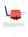
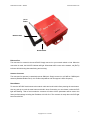
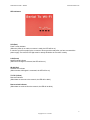
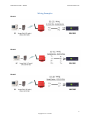
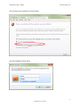
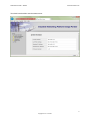
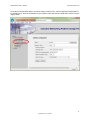
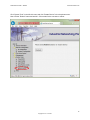
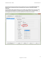
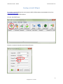
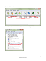
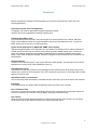
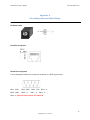
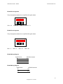
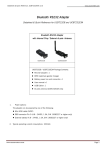
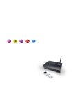
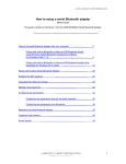
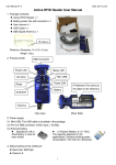
SERIAL TO WIFI CONVERTER
WF950
Quick start guide
Overview
…………………………………………..
1
Hardware
…………………………………………..
2
Wiring Examples
…………………………………
6
Configuring the parameters
………………...........
7
Creating a virtual COM port
……………………….
15
…………………………………………..
17
Parameters
Pin configuration and Cable Wiring
……………..
18
0
Copyrights © U.S. Converters
Serial WiFi Converter – WF950
www.usconverters.com
Overview
The WF950 is a solid high performance 1-port serial RS232, RS485, RS422 WiFi adapter (also called a
wireless device server), which will allow you to send and receive serial data over a standard WiFi
network.
It is designed around the popular Atheros AR2317 processor which offers great reliability and
performance including many features and functions rarely seen in this price range.
In Infrastructure mode or Ad-Hoc mode, the WF950 can communicate with any host computer through an
access point, or with another WF950 located up to 300 feet (100 meters) away.
Default settings
Wireless IP: 192.168.10.3 (https)
Wired IP: 192.168.10.2 (https)
Netmask: 255.255.255.0
Gateway: 192.168.10.1
Network type: Ad-hoc
TCP Server port: 4000
Network interface: Wired Ethernet
Baud rate: 38400bps
1
Copyrights © U.S. Converters
Serial WiFi Converter – WF950
www.usconverters.com
Hardware
Power
Outlet
DC-In
Serial Port
RS-485/RS-422
LAN
RJ-45
Serial Port
RS-232
Reset Button
LED Indicators
DC-In Power Outlet
The Serial to Wi-Fi Converter is powered by a single 12V DC (center +) power supply at 1.0A. A suitable
power supply adapter is part of the packaging. Connect the power line to the power outlet at the left side
of Serial to Wi-Fi Converter and put the adapter into the socket. If the power is properly supplied, the
“SYS” red color LED will be on after about 30 seconds. In some cases a reboot by pressing the reset
button might be required for the first time the converter is powered on.
2
Copyrights © U.S. Converters
Serial WiFi Converter – WF950
www.usconverters.com
DC-In
Power
Ethernet Port
Reset Button
Ethernet Port
The connector for network is the usual RJ45. Simply connect it to your network switch or Hub. When the
connection is made, the LAN LED indicator will light. When data traffic occurs on the network, red (Rx/Tx)
indicator will blink during data transferring and receiving.
Antenna Connector
The connector for antenna is a standard reverse SMA jack. Simply connect it to a 2.0dBi or 5.0dBi dipole
antenna (Standard Rubber Duck). It is 50 Ohms impedance and can support 2.4GHz frequency.
Reset Button
To reset the WF-950 first disconnect the network cable and serial cable before pressing the reset button.
Use any point tip to push the reset button and hold it about 5 seconds, you can release it when the SYS
light start flashing. After a few seconds the converter will reboot. All the parameters will be reset to the
factory default settings including the IP address 192.168.10.2. The converter is ready when the SYS light
becomes solid ON.
3
Copyrights © U.S. Converters
Serial WiFi Converter – WF950
www.usconverters.com
RS-422/RS-485
RS-232
Serial I/O Port of RS-232/RS-422/RS-485
Connect the serial data cable between the Wi-Fi converter and the serial device. Follow the parameter
setup procedures to configure the converter (see the following chapters).
4
Copyrights © U.S. Converters
Serial WiFi Converter – WF950
www.usconverters.com
LED Indicators
SYS (Red)
Power / ready indicator
(When the power is on and the converter is ready, the LED will be on.)
It can take up to 45 seconds for the converter to boot up and be ready after you have connected the
power supply. The red SYS LED light must be steady ON before the converter is ready.
LAN (Green)
Network signal indicator
(When the LAN signal is detected, the LED will be on.)
WLAN (Red)
Wireless Lan indicator
(When wireless LAN signal is connected, the LED will be on)
TX / RX (Yellow)
Data sent indicator
(When data are sent out to the network, the LED will be blink.)
Data received indicator
(When data are received from the network, the LED will be blink.)
5
Copyrights © U.S. Converters
Serial WiFi Converter – WF950
www.usconverters.com
Wiring Examples
RS-232
RS-422
RS-485
6
Copyrights © U.S. Converters
Serial WiFi Converter – WF950
www.usconverters.com
Configuring the parameters
Assign a static IP address to your network in the 192.168.10.xx subnet:
Connect the converter to the power supply and wait for the SYS LED light to be steady ON. Then connect
the Ethernet cable.
It can take up to 45 seconds for the converter to boot up and be ready after you have connected the
power supply. The red SYS LED light must be steady ON before the converter is ready.
Open a web browser and go to:
https://192.168.10.2/
Remember the secure HTTPS, not only HTTP.
7
Copyrights © U.S. Converters
Serial WiFi Converter – WF950
www.usconverters.com
Click “Continue to this website (not recommended).”
User and password are both: admin
8
Copyrights © U.S. Converters
Serial WiFi Converter – WF950
www.usconverters.com
You should now be able to see the status screen:
9
Copyrights © U.S. Converters
Serial WiFi Converter – WF950
www.usconverters.com
To enable the wireless interface, click on “IP Configuration” in the left side menu and select “Wireless”
from the drop-down menu. Select “DHCP” if you want to enable this.
Click the “Apply” button.
10
Copyrights © U.S. Converters
Serial WiFi Converter – WF950
www.usconverters.com
To be able to communicate with the converter using a wireless router, click the “Wireless Configuration” in
the left side menu, enter the credentials of your wireless router and click the “SSID Scan” button. Click the
“Apply” button.
11
Copyrights © U.S. Converters
Serial WiFi Converter – WF950
www.usconverters.com
Click “System Tools” in the left side menu and click “Restart Device” in the drop-down menu.
Now click the “Reboot” button and wait 30 – 50 seconds for the converter to reboot.
12
Copyrights © U.S. Converters
Serial WiFi Converter – WF950
www.usconverters.com
After the reboot is complete you should automatically be re-directed to the status screen:
13
Copyrights © U.S. Converters
Serial WiFi Converter – WF950
www.usconverters.com
To be able to connect to the converter using your wireless router you must first disconnect the wired
Ethernet cable. If the Ethernet cable is connected to the converter it cannot be accessed
wirelessly.
Once the Ethernet cable is disconnected you can now login to the converter over the air by using a web
browser and go to the IP address you gave the converter (remember HTTPS). If you have set the
wireless interface to DHCP then you can either login to your wireless router to see which IP address has
been assigned to the converter or you can use the EDS-Tool to search for the converter:
14
Copyrights © U.S. Converters
Serial WiFi Converter – WF950
www.usconverters.com
Creating a virtual COM port
For creating a virtual COM port we recommend the USC-VCOM software (downloadable for free from
www.usconverters.com).
Install and run the USC-VCOM software.
Click the “Add COM” button.
Enter the converter’s information and click the OK button:
15
Copyrights © U.S. Converters
Serial WiFi Converter – WF950
www.usconverters.com
The virtual COM port will be created:
Check in Device Manager to make sure the COM port has been successfully created:
16
Copyrights © U.S. Converters
Serial WiFi Converter – WF950
www.usconverters.com
Parameters
Most of the parameter settings are self-explanatory so we will here just mention a few of the more
unusual parameters:
Performance (under Serial Configuration).
Throughput: This mode is optimized for highest transmission speed.
Latency: This mode is optimized for shortest response time.
Automatic Data Buffer Flush
The received data will be queued in the internal buffer until all the delimiters are matched. When the
buffer is full (4K Bytes) or after the 'Flush Data Buffer' timeout, the data will also be sent. 'Flush Data
Buffer' timeout can be set from 0 to 65535 seconds.
System Event Notifications by SMTP Mail, SNMP Trap or Syslog
With the integrated System Log Configurator you can specify if you want to receive system notifications,
at what interval and also how you want to receive these, by email, SNMP Trap Server or TCP Server
Logs. The following notifications are available: Hardware Reset (Cold Start), Software Reset (Warm
Start), Login Failed, IP Address Changed, Password Changed, Access IP Blocked, Port Connected, Port
Disconnected.
Network Delimiter
A maximum of 4 delimiters (00-FF, Hex) can be defined for each direction. The data will be held until the
delimiters are received or the Flush Data Buffer times out.
Adjustable Alive Check
The serial device will send TCP alive-check packages in each defined time interval (Alive Check) to the
remote host to check the TCP connection. If the TCP connection is not alive, the connection will be closed
and the port will be freed.
Adjustable number of connections
You can manually select the number of simultaneous host connections you want to allow to the converter.
IP Filtering
This function will let you specify which IP addresses that can connect to the converter.
Force TX Interval Time
The Force TX interval time function specifies the timeout when no data has been transmitted. When the
timeout is reached or the TX buffer is full (4K Bytes), the queued data will be sent.
Idle Timeout
When the serial port stops data transmission for a defined period of time (Idle Timeout), the connection
will be closed and the port will be freed and try to connect with other hosts.
17
Copyrights © U.S. Converters
Serial WiFi Converter – WF950
www.usconverters.com
Appendix A
Pin configuration and Cable Wiring
DC Power outlet
RJ-45 Pin Assignment
RS-232 Pin Assignment
The pin assignment scheme for a 9-pin male connector on a DTE is given below.
PIN 1 : DCD
PIN 2 : RXD
PIN 5 : GND
PIN 6 : X
PIN 3 : TXD
PIN 7 : X
PIN 4 : X
PIN 8 : X
PIN 9 : X ﹙DC+5V Power Output- For Option﹚
18
Copyrights © U.S. Converters
Serial WiFi Converter – WF950
www.usconverters.com
RS-422 Pin Assignment
The pin assignment scheme for a 4-pin RS-422 is given below.
1
PIN 1 : R-
2
PIN 2 : R+
3 4
PIN 3 : T-
PIN 4 : T+
RS-485 Pin Assignment
The pin assignment scheme for a 4-pin RS-485 is given below.
1
PIN 1 : X
2
PIN 2 : X
3
4
PIN 3 : D-
PIN 4 : D+
RS-422 Wiring Diagram
Serial Device
RR+
TT+
WF-950 Converter
3 T4 T+
1 R2 R+
RS-485 Wiring Diagram
Serial Device
WF-950 Converter
D-
1 D-
D+
2 D+
19
Copyrights © U.S. Converters