1
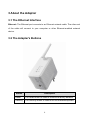
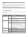
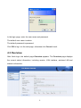
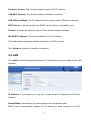
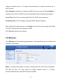
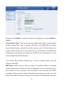
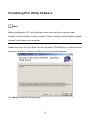
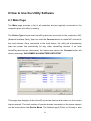
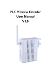
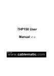
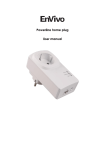
PL-200AV-PEW
USER MANUAL
Contents
1 Introduction .............................................................................................................. 1
1.1 Features ...................................................................................................... 1
1.2 System Requirements ................................................................................. 1
1.3 Package Contents ....................................................................................... 2
2 Safety Notice............................................................................................................ 3
3 About the Adapter..................................................................................................... 4
3.1 The Ethernet Interface ................................................................................. 4
3.2 The Adapter's Buttons ................................................................................. 4
3.3 The Adapter's LEDs..................................................................................... 5
3.4 Connecting the PL-200AV-PEW .................................................................. 6
4 Wi-Fi Web configuration........................................................................................... 7
4.1 Setting TCP/IP Properties............................................................................ 7
4.2 Login ............................................................................................................ 7
4.3 Overview...................................................................................................... 8
4.4 LAN.............................................................................................................. 9
4.5 Wireless ..................................................................................................... 10
4.6 Security...................................................................................................... 11
4.7 Management.............................................................................................. 13
5 Installing PLC Utility Software ................................................................................ 14
6 How to Use the Utility Software.............................................................................. 16
6.1 Main Page ................................................................................................. 16
6.2 Privacy page .............................................................................................. 19
6.3 Diagnostics page ....................................................................................... 21
6.4 About page................................................................................................. 23
7 How to Use the SECURITY Pushbutton ................................................................ 24
7.1 Creating a HomePlug AV Logical Network ................................................ 24
7.2 Joining a Network ...................................................................................... 25
7.3 Leaving a Network ..................................................................................... 26
Appendix A Specifications......................................................................................... 28
Appendix B Acronyms and Abbreviations ................................................................. 30
Appendix C About PLC QoS ..................................................................................... 31
PL-200AV-PEW USER MANUAL
1 Introduction
This PL-200AV-PEW wallmount
Wireless extender for transmitting data up to 200
Mbps across the household power line and every power socket becomes a WLAN
access point. Through the combination of these two technologies, you can wirelessly
surf on line conveniently in the complicated corner that is used to be unreachable with
wiring and data rate is up to 54 Mbps. It is suitable for using in a wide range of both
residential (in-home) and commercial (offices, apartments, hotels, warehouses)
network applications. No cables, no drilling. These adapters enable the effortless
creation of a high-speed network that supports video, voice and data.
1.1 Features
Wallmount type and power voltage range of 100 V to 240 V AC 50/60Hz
Compatible with IEEE 802.11b/g and HomePlug AV
Support QAM 256/64/16/8, QPSK, BPSK, and ROBO modulation schemes
Physical layer data rate up to 200 Mbps
128-bit AES link encryption for PLC
IEEE 802.11b/g
Support WAP, WAP2, 64/128/152-bit WEP, SSID hide
Wireless module supports AP and VAP mode
Support GUI WEB interface
1.2 System Requirements
Operating System: Microsoft Windows 2000 or XP, Vista 32-bit
CPU: Intel Pentium III or better, clock rate faster than 2.0GHz recommended
RAM: At least 128MB
Screen Resolution: Any resolution
1
Free Disk Space: At least 20MB
Network Interface: At least one fast Ethernet (100 Mbps) network card, and
Ethernet cord
1.3 Package Contents
PL-200AV-PEW x 1
CD ROM x 1
RJ45 Ethernet cable x 1
2
2 Safety Notice
This device is intended for connection to the AC power line. For installation
instructions, please refer to the installation section of this guide. The following
precautions should be taken when using this product.
Read all instructions before installing and operating this product.
Follow all warnings and instructions marked on the product.
Unplug the device from the wall outlet before cleaning. Use a damp cloth for
cleaning. Do not use liquid cleaners or aerosol cleaners.
Do not operate this product near water.
This product should never be placed near or over a radiator or heat register.
Do not use an extension cord between the device and the AC power source.
Only a qualified technician should service this product. Opening or removing
covers may result in exposure to dangerous voltage points or other risks.
Unplug the device from the wall outlet and refer the product to qualified service
personnel for the following conditions:
- If liquid has been spilled into the product
- If the product has been exposed to rain or water
- If the product does not operate normally when the operating instructions are
followed
- If the product exhibits a distinct change in performance
3
3 About the Adapter
3.1 The Ethernet Interface
Ethernet: The Ethernet port connects to an Ethernet network cable. The other end
of the cable will connect to your computer or other Ethernet-enabled network
device.
3.2 The Adapter's Buttons
Button
Description
Reset
The Reset button is used to restore the factory defaults.
Security
The Security button is used to set the membership state.
4
Note:
Restoring the PL-200AV-PEW factory defaults will erase all of settings that you have
set before, and replace them with the factory defaults. Please be careful for not
retaining the reset button if you want to retain the former settings.
3.3 The Adapter's LEDs
All adapter's LEDs are located on the front panel, there are 3 LEDs to indicate the
adapter’s status.
Indicator
Power(Green/Red)
Status
On
Description
When the LED is green, it indicates that the device
is ready for use.
Flash
When the LED is orange, it indicates that the
device is loading firmware.
PLC(Green/Red)
On
When the PLC indicator is green, it indicates that
powerline link is detected
Flash
When serving as a STATION, the LED is green
and flashes to indicate powerline activity.
When serving as a CCO, the LED is green and
lights steadily ON, even in the presence of
powerline activity.
LAN (Green)
WLAN (Green)
On
Ethernet link is detected
Flash
It indicates that data over Ethernet is activated.
On
WLAN link is detected.
Flash
It indicates that data over Wi-Fi link is activated.
5
3.4 Connecting the PL-200AV-PEW
Step 1
Put the PL-200AV-PEW to the AC power socket directly.
Step 2
Use one end of Ethernet network cable to connect to the
PL-200AV-PEW Ethernet port, and another end connect to your PC
Ethernet port.
6
4 Wi-Fi Web configuration
This chapter mainly describes how to configure the Access Point through Web page.
4.1 Setting TCP/IP Properties
The default IP address of PL-200AV-PEW is 192.168.1.1, you should set your PC’s IP
address in the same subnet.
4.2 Login
Open IE and enter http://192.168.1.1 at the URL column to log in to PL-200AV-PEW
web page.
7
In the login page, enter the user name and password.
The default user name is admin.
The default password is password.
Click OK to log in to the web page, otherwise click Cancel to exit.
4.3 Overview
After finish login, the default page Overview appears. The Overview page displays
the current status information, including version, LAN interface, wireless LAN and
statistic information.
8
Firmware Version: The current firmware version of Wi-Fi module.
LAN MAC Address: The physics address of Ethernet interface.
LAN IP/Subnet Mask: The IP address and the subnet mask of Ethernet interface.
DHCP Server: It shows whether the DHCP server function is enabled or not.
Channel: It shows the current channel of the wireless network settings.
WLAN MAC Address: The physics address of Wi-Fi interface.
This field shows the packets statistic information of Wi-Fi module
Click Update to refresh the statistic information.
4.4 LAN
Click LAN and the following page appears. This page allows you to configure the LAN
interface.
IP Address: If necessary, you may set a fixed private IP address for Ethernet
interface.
Subnet Mask: According to the net segment to set the subnet mask.
DHCP server automatically assigns an IP address to each computer on LAN,
9
unless it already has one. It is highly recommended you enable the device as a
DHCP server.
When Disable is selected, the function of DHCP server is shut off. When Enable is
selected, the function of DHCP server is activated and the following items appear.
Lease Time: The life time of assigned IP that the DHCP server leases to.
IP address Pool: The IP address range that DHCP Server leases to.
After finishing the settings above, click Apply, and then the new settings take effect.
The Wi-Fi module saves all changes to Flash.
Click Cancel to discard all changes.
4.5 Wireless
Click Wireless and the following page appears. This page allows you to configure the
wireless LAN interface.
Mode: It consists three types of modes, including 802.11b, 802.11b/g Compatible
and 802.11g Only. You may select the proper network mode. It is highly
recommended that you select 802.11b/g Compatible.
10
SSID (Service Set Identifier): The wireless network name shared among all the
devices is case-sensitive and must not exceed 32 alphanumeric characters which
may be any keyboard character. Make sure this setting is the same for all devices in
the wireless network.
Channel: Select the proper channel in the drop-down list. All devices in the wireless
network must use the same channel in order to run correctly.
Beacon Interval: If the value of beacon interval is small, it can accelerate the link
speed. If the value is big, it can help to save power. The interval time range is
between 25 and 500. The default value is 100.
Data Rate: It is the wireless physics rate. It is highly recommended that you select
Auto. If you select Auto, the data rate will automatically negotiate with other
devices according to the situation. For a fixed data rate, you should set the proper
data rate according to the Wi-Fi mode (such as 802.11b or 802.11g).
After finishing the settings above, click Apply, and then the new settings take effect.
The Wi-Fi module saves all changes to Flash.
Click Cancel to discard all changes.
4.6 Security
Click Security and the following page appears. This page allows you to configure
security for the wireless LAN interface.
11
Encrypt: Select Enable to enable VAP security configuration or select Disable to
disable it.
Authentication Type: There are five types of authentication types, including Open
System, Shared Key, Open & Shared, WPA-PSK, and WPA2-PSK.The default
value is Open System, and also Shared Key can be used. For Open System, the
sender and the recipient do not use a WEP key for authentication. For Shared Key
authentication, the sender and recipient use a WEP key for authentication. In most
cases, please keep the default value.
If you select Open System, Shared Key, or Open & Shared mode, you may
configure VAP WEP.
WEP Key1-4: WEP keys are used to create an encryption scheme for wireless
network transmissions. When not using a Passphrase, you can manually enter a
set of values, and do not leave a key field blank. If you are using 64-bit WEP
encryption, the key must be exactly 10 hexadecimal characters in length. If you are
using 128-bit WEP encryption, the key must be exactly 26 hexadecimal characters
12
in length. Valid hexadecimal characters are “0”-“9” and “A”-“F”.
4.7 Management
Click Management and the following page appears. This page allows you to upgrade
the firmware.
Fireware Upgrade:Current Firmware Version: This field shows the current
firmware version.
Locate New Firmware: Click Browse to select the new firmware in your PC. Click
Upgrade to download the new firmware to the device.
Restore Factory Defaults: Click the Restore button, then the all current
configuration returns to factory default.
Click the Save button, the all configuration will be stored into Flash.
New Password: Set a new password for logging in to the Wi-Fi web.
Confirm Password: Enter the new password again.
After finishing the settings above, click Apply, and then the new settings take effect.
The Wi-Fi module saves all changes to Flash.
Click Cancel to discard all changes.
13
5 Installing PLC Utility Software
Note:
Before installing the PLC utility software, make sure that there is no any other
Powerline Utility installed on your computer. If there is another utility installed, please
uninstall it and restart your computer.
Please insert the utility CD-ROM into the computer’s CD-ROM drive. Double click the
setup.exe, and then a page for installing the utility software appears.
Click Next to show the following page.
14
Click Browse to select the installation folder, and then click Next to continue.
Click Close to finish the installation.
15
6 How to Use the Utility Software
6.1 Main Page
The Main page provides a list of all powerline devices logically connected to the
computer when the utility is running.
The Device Type shows local HomePlug devices connected to the computer’s NIC
(Network Interface Card). User can click the Connect button to make NIC connect to
the local devices. Once connected to the local device, the utility will automatically
scan the power line periodically for any other HomePlug devices. If no local
HomePlug devices are discovered, the status area above the Connect button will
show a message “NO HOMEPLUG ADAPTERS DETECTED”.
This page also displays all the HomePlug remote devices discovered on the current
logical network. The total number of remote devices connected on the same network
can be found above the Device Name. The Network type (Public or Private) is also
16
displayed based on the network status of the local device. The scan status option is
displayed on the top right corner above the MAC Address. The following information
for all devices is displayed in the page.
Device Name
This field shows the default device name. User may modify the name by either using
the Rename button or by clicking on the name to edit it.
MAC Address
This field shows the remote device’s MAC address.
Password
By default, this field is blank. Click Enter Password button, user may modify the
password.
To set the Password of the device (It is necessary when creating a private network),
first select the device by clicking on its name and then click the Enter Password
button. Set Device Password dialog box appears for setting the password. Enter
your password in the password field. The password can be in any case formats, with
or without dashed between them. Click OK to confirm the password.
A confirmation box will appear if the password was entered correctly. If a device was
not found, system will pop up the prompt for trouble shooting. This process may take
a few seconds to get completed.
17
Add
This button is used to add a remote device to the existing network by entering the
device password of the device. A Add Device to Network dialog box appears. You
are allowed to set the device name and the password.
A confirmation box will appear if the password was entered correctly and if the device
was found in the powerline network. If a device was not found, system will pop up the
prompt for trouble shooting.
18
Note:
The device must be present on the power line (plugged in) in order for the password
to be confirmed and added to the network. If the device could not be located, a
warning message will be shown.
Scan
This button is used to search the HomePlug devices connected to the Powerline
network. By default, the utility automatically scans every few seconds and updates
the information.
6.2 Privacy page
The Privacy page allows you to create a private network to keep the security of
logical network.
All HomePlug devices are using a default logical network (network name), usually
19
“HomePlug”. The Privacy page allows user to change to a private network by
modifying the network name (network password) of devices.
The user can always reset to the HomePlug network (Public) by entering “HomePlug”
as the network name or by clicking on the Use Default (Public Network) button.
Note:
Changing the network name to anything other than HomePlug, the main page will
show the network type as Private.
Set Local Device Only
This button can be used to change the network name (network password) of the local
device. If a new network password is entered, all the devices displayed on the
previous main page will be no longer existed in the new network. Therefore, the local
20
device can not communicate with the devices in the previous logical network. Devices
previously set with the same logical network (same network name) will appear in the
device list after selecting this option.
Set All Devices
This button is used to change the logical network of all devices that appear on the
main page whose Device’s Password had been entered in the same logical network.
After finishing modifying, a dialog box appears to remind you that the operation is
successful. If the device password is not entered, it reminds you that the operation is
failed.
6.3 Diagnostics page
The Diagnostics page shows the information about system and the history of all
remote devices over a period of time.
The System Information shows software and hardware technical specifications of
21
the host computer on the Powerline network. It includes the following information.
z
Operating system platform or version
z
Host Network Name
z
User Name
z
MAC Address of all NICs (Network interface card) connected to the host
z
Versions of all Driver DLLs and libraries used (NDIS) (optional)
z
HomePlug chipset manufacturer name (Turbo Only devices)
z
MAC firmware version (Turbo Only devices)
z
MAC addresses of all devices connected locally to the host
z
Version of the configuration utility
z
Vendor name
The Lower panel contains the history information of all remote devices displayed on
the computer over a certain period of time. All devices that were on the powerline
network are listed here along with a few other parameters. Devices that are active on
the current logical network will show a transfer rate in the Rate field. For the devices
on the other networks, or devices that may no longer exist, “?” symbols are shown in
the corresponding Rate fields. Remote Divice History displays the following
information.
z
Device alias name
z
Device MAC address
z
Device password
z
Up-to-the-minute rate
z
Up-to-the-minute network name
z
HomePlug chipset manufacturer name
z
Up-to-the-minute date and time
z
MAC firmware version
The diagnostics information displayed may be saved as a text file for backup, or can
be printed for reference as technical support. For the devices that are not part of the
22
network anymore, can be deleted by using the delete button. A dialog box pops up
with a confirmation message if we try to delete a device whose password has been
entered.
6.4 About page
The About screen shows the software version and provides a HTML link to the
manufactory website.
Preferences
You may select enable or disable auto-scan feature.
23
7 How to Use the SECURITY Pushbutton
This section describes how to add new devices to, or remove old devices from a
HomePlug AV logical network(AVLN)by using a SECURITY pushbutton.
The operation progress and outcome can be monitored by observing the status of the
Power LED.
7.1 Creating a HomePlug AV Logical Network
If you want to create a logical network through two devices with different SECURITY
values and the two devices are connected to the same powerline, you can follow the
steps below.
Step 1
Press the SECURITY button on the first device A for less than 3 seconds.
Step 2
Press the SECURITY button on the second device B for less than 3
seconds. The button on device B must be pressed within 1 minute.
Step 3
Wait for the connection between A and B to complete.
The Power LED on both devices will flash evenly at 1-second intervals until the
operation succeeds or fails. If the operation succeeds, the power LED will illuminate
steadily. If an error occurs, the power LED on the ‘adder’ will flash unevenly until the
pushbutton on the ‘adder’ is pressed again or the ‘joiner’ is reset by holding the
pushbuttons down for more than 10 seconds.
24
A
PLC
B
PLC
C
PLC
A and B are not part of AVLN
A and B want to form an AVLN
Press NMK button on A less than 3 sec.
Press NMK button on B less than 3 sec.
A becomes “joiner”
B becomes “joiner”
B determines that A MAC address < B MAC address
B becomes “adder”
A accepts NMK from B
7.2 Joining a Network
In this scenario a network exists, a new device, the ‘joiner’, wants to join the network.
Any device on the existing network can become the ‘adder’.
Step 1
Press the pushbutton on the ‘joiner’ for at least 3 seconds.
Step 2
Press the pushbutton on any network device for less than 3 seconds,
making it the ‘adder’. Please press this pushbutton within 1 minute.
Step 3
Wait for connection to complete.
The Power LED on both devices will flash at 1-second intervals until the process
succeeds or fails. It will illuminate steadily on success. If an error occurs, the Power
LED on the ‘adder’ will flash unevenly until the pushbutton on the ‘adder’ is pressed
again or the ‘joiner’ is reset by pressing the pushbutton for more than 10 seconds.
25
A
PLC
B
PLC
C
PLC
A and B form an AVLN
C wants to join the AVLN
Press NMK button on B less than 3 sec.
Press NMK button on C less than 3 sec.
B becomes “adder”
C becomes “joiner”
C accepts NMK from B
7.3 Leaving a Network
A network exists. The user wants to remove one device, the ‘leaver’, from that
network, for whatever reason. He may want to remove the device from service
altogether or have it join another logical network.
Step 1
Press the pushbutton on the ‘leaver’ for at least 10 seconds. The device
will reset and restart with a random SECURITY.
Step 2
Wait for reset to complete.
The Power LED on the ‘leaver’ will momentarily extinguish during reset, flash during
restart then illuminate steadily. No errors can occur.
Once the process completes, the user may disconnect the device from the medium or
join it to another logical network on the same medium.
26
A
PLC
B
PLC
C
PLC
A, B and C form an AVLN
A wants to leave the AVLN
Press NMK button on A more than 10 sec.
A computes random NMK
C resets and restarts
27
Appendix A Specifications
PLC Module SPEC
PLC Chipset
Intellon INT6400/INT1400
Serial Flash
16MB
SDRAM:
128MB
Firmware
Support North America/Europe/APAC/Japan
Protocol
HomePlug AV, coexists with existing HomePlug 1.0
PLC Rate
200Mbps
Data Rate
65Mbps TCP
90Mbps UDP
Modulation Band
2 MHz~30MHz
Modulation Schemes
Support 1024/256/64/16/8-QAM, QPSK,BPSK and ROBO
Encryption
128-bit AES
QoS
Support contention-free access, four-level priority based
contention access, and multi segment bursting
Support VLAN Priority
Support ToS and CoS Packet Classifier
Work Mode
TDMA and priority based CSMA/CA
Multicast Support
Supports IGMP managed multicast sessions
Wi-Fi Module SPEC
Wireless Chipset
Atheros AR2317
Protocol
IEEE 802.11b/g
Wireless Rates
For 802.11b: 11 Mbps, 5.5 Mbps, 2 Mbps, and 1Mbps
For 802.11g: 54 Mbps, 48 Mbps, 36 Mbps, 24 Mbps, 18
Mbps, 12 Mbps, 9 Mbps and 6Mbps
Security
WPA, WPA2, 64/128/152-bit WEP, Hide SSID
28
MAC Address Access Control List
Frequency Range
2.4GHz~2.4835GHz
Work Mode
Access Point
System SPEC
System Support
Windows 98SE, 2000, ME, XP 32/64 bit and Vista 32/64bit
LED’s
Power: The power LED lights up when the adapter is
powered on.
PLC: PLC link and activity
LAN: Ethernet link and activity
WLAN: Wireless link and activity
Push Button
Reset: Reset system or restore the factory defaults.
Security: Used to set the membership state.
Ethernet Interface
1 x RJ45 for 10/100 Ethernet (Auto MDI/MDI-X)
Consumption
5.5W (Max)
Environment Requirement
Operating Temperature
0ºC~40ºC
Storage Temperature
-20ºC~70ºC
Operating Humidity
10%~85%, non-condensing
Storage Humidity
5%~90%, non-condensing
Input Rating
100V-240 V AC, 50/60Hz
EMC and Safety
Regulatory
FCC Part 15 Class B
Compliance
CE
Safety Regulations
UL
Green Standard
RoHS
Physical Characteristics
Dimension
L×W×H: 117mm×75mm×47mm
Weight
216g
29
Appendix B Acronyms and Abbreviations
AV In-home Logical Network, the AVLAN is the set of
AVLN
CCo
STAs that possess the same network Membership key,
every AVLN is managed by a single CCo
Central Coordinator, the CCo is a superset of a STA
which provisioning of terminal equipment identifiers and
global link identifiers
CSMA/CA
Carrier Sense Multiple Access / Collision Avoidance
DAK
Device Access Key
IGMP
Internet Group Management Protocol
NEK
Network Encryption Key
NID
Network ID (Identification)
SECURITY
Network Membership Key
PLC
Power Line Communication
PIB
Parameter Information Block
STA
Station, a STA in the network with a connection to the
power line and being able to source or sink traffic
TDMA
Time Division Multiple Access
TEI
Terminal Equipment Identifier
TOS
Type Of Service
VLAN
Virtual Local Area Network
30
Appendix C About PLC QoS
PL-200AV-PEW allows 4 levels of Channel Access Priority CAP (0~3). The 8 levels of
VLAN Ethernet tags must be mapped to the 4 levels of CAP priority, where CAP 3 is
the highest priority and CAP 0 is the lowest. CAP 3 priority might be used for voice
and network management frames. CAP 2 is used for streaming video and music
while CAP 1 and CAP 0 are used for data.
Default CAP
The ‘Default CAP’ group allows for default priority mapping of packets that do not
have a VLAN TAG. Settings are available for Unicast (directed to a host).
IGMP - (default CAP 3) - sets the channel access priority for IGMP frames - these
are the group management frames, not the stream data.
Unicast - (default CAP 1) - sets the default channel access priority for unicast
frames not matching any other classification or mapping.
IGMP managed Multicast Stream (Fixed to CAP 2) - sets the default channel
access priority for stream data belonging to a snooped IGMP multicast group.
Multicast/Broadcast - sets the default CAP for multicast frames not in a snooped
group and for broadcast frames.
The following are the factory default settings for VLAN Tags and TOS Bits:
VLAN Tag
Default CAP
TOS Bit User
Default CAP
User riority
Priority
Priority
Priority
0
CAP1
0
CAP1
1
CAP0
1
CAP0
2
CAP0
2
CAP0
3
CAP1
3
CAP1
31
4
CAP2
4
CAP2
5
CAP2
5
CAP2
6
CAP3
6
CAP3
7
CAP3
7
CAP3
32