1
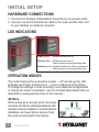
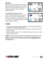
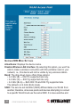
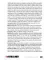
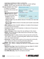
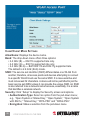
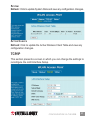
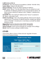
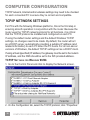
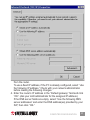
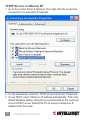
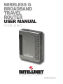
Wireless G
Broadband
Travel
Router
user manual
Model 523875
INT-523875-UM-0807-03
Thank you for purchasing the INTELLINET NETWORK SOLUTIONS™
Wireless G Broadband Travel Router, Model 523875.
This router is equipped with two 10/100 M auto-sensing Ethernet ports
for connecting to a LAN and cascading to another similar router. It also
features 64/128-bit WEP encryption, WPA and IEEE802.1x to provide a
high level of security to protects users’ data and privacy. The MAC address
filter prevents access to your wireless LAN from unauthorized MAC
addresses, thus doubling network security, and the easily configured
Web-based management utility ensures that your wireless network
connection is always solid and hassle-free. allowing you to enjoy the
benefits of these additional features:
• Compact design, great for traveling
• Up to 54 Mbps network data transfer rate
• Compatible with all 802.11b & g wireless products
• DHCP server assigns IP addresses for all LAN users
• Supports virtual server and DMZ (demilitarized zone)
• Supports Access Point mode, Gateway (Router) and Client mode
• Supports UPNP (Universal Plug and Play)
• Supports VPN pass-through (IPSec, PPTP, L2TP)
• Content control through URL filter
• Remote management function (enable/disable and management port)
• Lifetime Warranty
Package Contents
• Wireless G Broadband Travel Router
• Ethernet Cat5 RJ-45 cable, 1.0 m (3 ft.)
• User manual
FCC Certifications
This equipment has been tested and found to comply with the limits for a
Class B digital device, pursuant to Part 15 of the FCC rules. These limits
are designed to provide reasonable protection against harmful interference
in a residential installation. This equipment generates, uses and can radiate
radio frequency energy and, if not installed and used in accordance with the
instructions, may cause harmful interference to radio communications.
However, there is no guarantee that interference will not occur in a particular
installation. If this equipment does cause harmful interference to radio or
television reception, which can be determined by turning the equipment off
and on, the user is encouraged to try to correct the interference by one or
more of the following measures:
• Reorient or relocate the receiving antenna.
• Increase the separation between the equipment and receiver.
• Connect the equipment into an outlet on a circuit different from that to
which the receiver is connected.
• Consult the dealer or an experienced radio/TV technician for help.
CAUTION: Any changes or modifications not expressly approved by the
grantee of this device could void the user’s authority to operate the equipment.
This device complies with Part 15 of the FCC rules. Operation is subject
to the following two conditions: (1) This device may not cause harmful
interference, and (2) this device must accept any interference received,
including interference that may cause undesired operation.
FCC RF R adiation Exposure Statement
This equipment complies with FCC RF radiation exposure limits set forth
for an uncontrolled environment. This equipment should be installed and
operated with a minimum distance of 20 cm between the radiator and
your body.
CE Mark Warning
This is a Class B product. In a domestic environment, this product may
cause radio interference, in which case the user may be required to take
adequate measures.
table of contents
section page
Initial Setup..........................................................................................6
Hardware Connections.................................................................6
LED Indicators..............................................................................6
Operation Modes..........................................................................6
Login.............................................................................................7
Configuration via the Web.................................................................8
Mode (Operation/Wireless Mode)................................................8
Status................................................................................................ 26
TCP/IP........................................................................................ 27
Other.......................................................................................... 28
Computer Configuration..................................................................30
TCP/IP Network Settings............................................................30
Internet Access........................................................................... 40
Wireless LANs & Station Configuration...................................... 42
Troubleshooting................................................................................44
Specifications...................................................................................46
NOTE: Some screen-shot images have been modified to fit the format
of this user manual.
CONTENTS
initial setup
Hardware Connections
1. Connect the Wireless G Broadband Travel Router to a power outlet.
2. Connect one end of the Ethernet cable to the router and the other end
to your desktop or notebook computer.
led indicators
Po w e
r
s
Wirele
s
et
Ethern
Power (green) Solid when device is on.
Wireless (blue) Solid when device is on.
Flashing when receiving/sending data.
Ethernet (green) Solid when Ethernet cable is connected.
Flashing when receiving/sending data.
operation modes
The router features three operation modes — AP (access point), GW
(gateway) and Client Infrastructure — and is configured at the factory.
To change the settings in order to employ more advanced configurations
or change the mode of operation, use the included Web-based utility as
described in subsequent sections of this manual.
AP Mode
When acting as an access point, the router
connects all stations (desktop/notebook with
wireless network adapter) to a wired network.
All stations can have Internet access if only
the router is connected to the Internet.
INITIAL SETUP
GW Mode
When GW mode is selected, the access
point will enter the gateway mode, and the
wireless connection will be set up from a
point-to-point local LAN to a point-tomultipoint WAN.
Client Mode (Infrastructure)
If set to Client (Infrastructure) mode, this
device can work like a wireless station
when it’s connected to a computer so that
the computer can send packets from wired
end to wireless interface.
LOGIN
1. Turn on your computer and connect it to the Wireless G Broadband
Travel Router with an Ethernet cable.
2. Make sure your wired station is set to the same subnet as the router: 192.168.1.254.
3. Start your Web browser. In the “Address” field on the menu bar, enter
“http://192.168.1.254.”
NOTE: No username or password is required for the initial login; you do,
however, have the option of setting up a username and password for
added security. (See the Password subsection in Configuration via
the Web/Other.)
INITIAL SETUP
configuration via the web
The Configuration menu on the upper panel is divided into four main
sections: Mode (operation/wireless mode), Status, TCP/IP and Other.
Select a section, then click the “Setup” button that corresponds to the
desired subsection (e.g., Mode ‡ Access Point, as shown below).
Mode (operation/Wireless Mode)
CONFIGURATION VIA THE WEB
Access Point/AP Mode Settings
Alias Name: Displays the device name.
Disable Wireless LAN Interface: By selecting this option, you won’t be
able to make a wireless connection with this access point in your
network; i.e., this device will not be visible by any wireless station.
Band: The drop-down menu offers three options:
• 2.4 GHz (B) — 802.11b supported rate only.
• 2.4 GHz (G) — 802.11g supported rate only.
• 2.4 GHz (B+G) — Both 802.11b and 802.11g supported rate.
The default is 2.4 GHz (B+G) mode.
SSID: The service set identifier (SSID) differentiates one WLAN from
another; therefore, all access points and devices attempting to connect
to a specific WLAN must use the same SSID. It is case-sensitive and
must not exceed 32 characters. A device will not be permitted to join the
basic service set (BSS) unless it can provide the unique SSID. An SSID
is also referred to as a network name because, essentially, it is a name
that identifies a wireless network.
Channel Number: Allows you to set the channel manually or automatically.
To set manually, just select the channel you want to specify. If “Auto” is
selected, you can set the range so the router automatically surveys and
chooses the channel with the best situation for communication. The
number of channels supported depends on the access point’s region.
All stations communicating with the AP must use the same channel.
Security: Click “Setup” to display the Security screen and options.
•Authentication: Select an
option from the pull-down
menu; e.g., “Open system
or Shared Key,” “Open
System,” “Open System
with 802.1x,” “Shared Key,”
“WPA-RADIUS,” “WPA-PSK,” WPA2-RADIUS” and “WPA2-PSK.”
•Encryption: In the pull-down menu, select either “None” or “WEP.”
-Use 802.1x Authentication: Select 64-bit or 128-bit encryption.
Select “HEX” if using hexadecimal numbers (0-9, or A-F). Select
“ASCII” if using ASCII (case-sensitive) characters. Ten hexadecimal CONFIGURATION VIA THE WEB
digits or five ASCII characters are needed if 64-bit WEP is used;
26 hexadecimal digits or 13 ASCII characters if 128-bit WEP is
used.
-Pre-Shared Key Format: Select “Passphrase” or “Hex” (64
characters).
- Pre-Shared Key: Pre-Shared Key serves as a password. Key in an
8- to 63-character string to set the password or leave it blank, in
which case the 802.1x Authentication will be activated. Make sure
the same password is used on the client end.
-Group Key Life Time: Enter the number of seconds that will elapse
before the group key changes automatically. The default is 86,400
seconds.
•Enable Pre-Authentication: This enables secure fast roaming without noticeable signal latency. Pre-authentication provides a way to establish a PMK (pairwise master key) security association before a client connects, with the advantage being that the client reduces the time that it’s disconnected to the network.
-Authentication RADIUS Server: RADIUS is an authentication
authorization and accounting client-server protocol. The client is
a network access server which has access to a user database with
authentication information and which desires to authenticate its
links.
- Port: Enter the RADIUS server’s port number provided by your ISP.
The default is 1812.
-IP Address: Enter the RADIUS server’s IP address provided by
your ISP.
-Password: Enter the password that the AP shares with the RADIUS
server.
•Enable Accounting: Check to enable this function.
-Accounting RADIUS Server: Enter the port, IP address and
password as above.
•Apply Changes: Click to save and apply the current settings.
•Reset: Click to clear and reset the current settings.
10
CONFIGURATION VIA THE WEB
Advanced
Settings: Click
“Setup” to
display the
Wireless
Advanced
Settings
screen and
options.
•Fragment
Threshold: This is a mechanism for improving efficiency when high traffic flows along in the wireless network. If your 802.11g wireless LAN adapter frequently transmits large files in the wireless network, you can enter a new fragment threshold value to split the packet.
The value can be set from 256 to 2346; the default value is 2346.
•RTS Threshold: This is a mechanism implemented to prevent the
“Hidden Node” problem, a situation in which two stations are within
range of the same access point but not within range of each other
(and are thus “hidden” from each other). When a station starts to send
data to the access point, it might not notice that the other station is
already using the wireless medium. When these two stations send
data at the same time, the transmissions might collide when arriving
simultaneously at the access point, with the collision most certainly
resulting in a loss of messages for both stations. When enabling RTS
Threshold on a suspect “hidden station,” this station and its access
point will use a request to send (RTS — also known as “ready to
send”), in which the station informs the access point that it is going
to transmit the data. Upon receipt, the access point will respond with
a clear to send (CTS) message to all stations within its range to notify
all other stations to defer transmission. It will also confirm to the
requesting station that the access point has reserved it for the
timeframe of the requested transmission. NOTE: If the “Hidden Node”
problem is an issue, specify the packet size: The RTS mechanism
will be activated if the data size exceeds the value you set. The default
value is 2346. CAUTION: Enabling RTS Threshold will cause CONFIGURATION VIA THE WEB
11
redundant network overhead that could negatively affect the
throughput performance instead of providing a remedy. This value
should remain at its default setting of 2346. Should you encounter
inconsistent data flow, only minor modifications of this value are
recommended.
•Beacon Interval: This is the time between beacon transmissions.
Before a station enters Power Save mode, the station needs the
beacon interval to know when to wake up to receive the beacon (and
learn whether there are buffered frames at the access point).
•Inactivity Time: The default setting is 30,000 ms.
•Data Rate: By default, the unit adaptively selects the highest possible
rate for transmission. Select the basic rates to be used among the
following options: “Auto,” “1,” “2,” “5.5,” “11” or “54 Mbps.” For most
networks, the default setting is “Auto,” which is the best choice. When
set to “Auto,” the transmission rate will select the optimal rate. If
obstacles or interference is present, the system will automatically
fall back to a lower rate.
•Preamble Type: A preamble is a signal used in wireless environment
to synchronize the transmitting timing, including Synchronization and
Start frame delimiter. NOTE: If you want to change Preamble Type
to “Long” or “Short,” check the setting of the access point.
•Broadcast SSID: With “Enabled” selected, this wireless access
point will broadcast its SSID to stations; when set to “Disabled,” it
won’t. If stations want to connect to this wireless AP, its SSID should
be known in advance to make a connection.
•Apply Changes: Click to save and apply the current settings.
•Reset: Click to clear and reset the current settings.
Access Control: Click “Setup” to
display the Wireless Access
Control screen and options.
•Wireless Access Control
Mode: Select on option
from the pull-down menu.
-Disable: Select to disable
this mode.
12
CONFIGURATION VIA THE WEB
-Allow Listed: Only the stations shown in the table can associate with the AP.
-Deny Listed: Stations shown in the table won’t be able to associate
with the AP.
•MAC Address: Enter the MAC address of a station that’s allowed
to access this access point.
•Comment: Enter up to 20 characters in reference to the previous
MAC Address field.
•Apply Changes: Click to save the new settings on the screen.
•Reset: Click to discard the data entered since the last time “Apply
Changes” was clicked.
•Delete Selected: To delete clients on the access list (to this AP),
click “Select” next to the corresponding MAC address and comments,
then click “Delete Selected.”
•Delete All: To delete all the clients on the access list (to this AP),
click “Delete All” without selecting individual addresses.
•Reset: Click “Reset” to clear any/all selected items.
WDS Setting: Click “Setup”
to display the WDS
(wireless distribution
system) Setting screen
and options.
•MAC Address: Enter
the MAC address of a
station that’s allowed
to access this AP.
•Comment: Enter up to 20 characters in reference to the previous
MAC Address field.
•Apply Changes: Click to save the new settings on the screen.
•Reset: Click to discard the data entered since the last time “Apply
Changes” was clicked.
CONFIGURATION VIA THE WEB
13
Gateway/GW Mode Settings
Alias Name: Displays the device name.
Disable Wireless LAN Interface: By selecting this option, you won’t be
able to make a wireless connection with this portable router in your
network; i.e., this device will not be visible by any wireless station.
Band: The drop-down menu offers three options:
• 2.4 GHz (B) — 802.11b supported rate only.
• 2.4 GHz (G) — 802.11g supported rate only.
• 2.4 GHz (B+G) — Both 802.11b and 802.11g supported rate.
The default is 2.4 GHz (B+G) mode.
SSID: The service set identifier (SSID) differentiates one WLAN from
another; therefore, all access points and devices attempting to connect
to a specific WLAN must use the same SSID. It is case-sensitive and
14
CONFIGURATION VIA THE WEB
must not exceed 32 characters. A device will not be permitted to join the
basic service set (BSS) unless it can provide the unique SSID. An SSID
is also referred to as a network name because, essentially, it is a name
that identifies a wireless network.
Channel Number: Allows you to set the channel manually or automatically.
To set manually, just select the channel you want to specify. If “Auto” is
selected, you can set the range so the router automatically surveys and
chooses the channel with the best situation for communication. The
number of channels supported depends on the router’s region. All
stations communicating with the router must use the same channel.
Security: Click “Setup” to display the Security screen and options.
•Authentication: Select an
option from the pull-down
menu; e.g., “Open system
or Shared Key,” “Open
System,” “Open System
with 802.1x,” “Shared Key,”
“WPA-RADIUS,” “WPA-PSK,” WPA2-RADIUS” and “WPA2-PSK.”
•Encryption: In the pull-down menu, select either “None” or “WEP.”
-Use 802.1x Authentication: Select 64-bit or 128-bit encryption.
Select “HEX” if using hexadecimal numbers (0-9, or A-F). Select
“ASCII” if using ASCII (case-sensitive) characters. Ten hexadecimal digits or five ASCII characters are needed if 64-bit WEP is used; 26 hexadecimal digits or 13 ASCII characters if 128-bit WEP is used.
-Pre-Shared Key Format: Select “Passphrase” or “Hex” (64
characters).
- Pre-Shared Key: Pre-Shared Key serves as a password. Key in an
8- to 63-character string to set the password or leave it blank, in
which case the 802.1x Authentication will be activated. Make sure
the same password is used on the client end.
-Group Key Life Time: Enter the number of seconds that will elapse
before the group key changes automatically. The default is 86,400
seconds.
•Enable Pre-Authentication: This enables secure fast roaming CONFIGURATION VIA THE WEB
15
without noticeable signal latency. Pre-authentication provides a way
to establish a PMK (pairwise master key) security association before a client connects, with the advantage being that the client reduces the time that it’s disconnected to the network.
-Authentication RADIUS Server: RADIUS is an authentication
authorization and accounting client-server protocol. The client is a network access server which has access to a user database with
authentication information and which desires to authenticate its links.
- Port: Enter the RADIUS server’s port number provided by your ISP.
The default is 1812.
-IP Address: Enter the RADIUS server’s IP address provided by your ISP.
-Password: Enter the password that the AP shares with the RADIUS
server.
•Enable Accounting: Check to enable this function.
-Accounting RADIUS Server: Enter the port, IP address and
password as above.
•Apply Changes: Click to save and apply the current settings.
•Reset: Click to clear and reset the current settings.
Advanced
Settings: Click
“Setup” to
display the
Wireless
Advanced
Settings
screen and
options.
•Fragment
Threshold: This is a mechanism for improving efficiency when high traffic flows along in the wireless network. If your 802.11g wireless
LAN adapter often transmits large files in the wireless network, you
can enter a new fragment threshold value to split the packet. The value can be set from 256 to 2346; the default value is 2346.
•RTS Threshold: This is a mechanism implemented to prevent the
16
CONFIGURATION VIA THE WEB
“Hidden Node” problem, a situation in which two stations are within
range of the same access point but not within range of each other
(and are thus “hidden” from each other). When a station starts to send
data to the access point, it might not notice that the other station is
already using the wireless medium. When these two stations send
data at the same time, the transmissions might collide when arriving
simultaneously at the access point, with the collision most certainly
resulting in a loss of messages for both stations. When enabling RTS
Threshold on a suspect “hidden station,” this station and its access
point will use a request to send (RTS — also known as “ready to
send”), in which the station informs the access point that it is going
to transmit the data. Upon receipt, the access point will respond with
a clear to send (CTS) message to all stations within its range to notify
all other stations to defer transmission. It will also confirm to the
requesting station that the access point has reserved it for the
timeframe of the requested transmission.
•Beacon Interval: This is the time between beacon transmissions.
Before a station enters Power Save mode, the station needs the
beacon interval to know when to wake up to receive the beacon (and
learn whether there are buffered frames at the access point).
•Inactivity Time: The default setting is 30,000 ms.
•Data Rate: By default, the unit adaptively selects the highest possible
rate for transmission. Select the basic rates to be used among the
following options: “Auto,” “1,” “2,” “5.5,” “11” or “54 Mbps.” For most
networks, the default setting is “Auto,” which is the best choice. When
set to “Auto,” the transmission rate will select the optimal rate. If
obstacles or interference is present, the system will automatically
fall back to a lower rate.
•Preamble Type: A preamble is a signal in a wireless environment used to synchronize the transmitting timing, including Synchronization
and Start frame delimiter. NOTE: If you want to change Preamble
Type to “Long” or “Short,” check the setting of the access point.
•Broadcast SSID: With “Enabled” selected, this wireless access
point will broadcast its SSID to stations; when set to “Disabled,” it
won’t. If stations want to connect to this wireless AP, its SSID should CONFIGURATION VIA THE WEB
17
be known in advance to make a connection.
•Apply Changes: Click to save and apply the current settings.
•Reset: Click to clear and reset the current settings.
Access Control: Click “Setup”
to display the Wireless
Access Control screen and
options.
•Wireless Access Control
Mode: Select on option
from the pull-down menu.
-Disable: Select to
disable this mode.
-Allow Listed: Only the stations shown in the table can associate with the AP.
-Deny Listed: Stations shown in the table won’t be able to associate
with the AP.
•MAC Address: Enter the MAC address of a station that’s allowed
to access this access point.
•Comment: Enter up to 20 characters in reference to the previous
MAC Address field.
•Apply Changes: Click to save the new settings on the screen.
•Reset: Click to discard the data entered since the last time “Apply
Changes” was clicked.
•Delete Selected: To delete clients on the access list (to this AP),
click “Select” next to the corresponding MAC address and comments,
then click “Delete Selected.”
•Delete All: To delete all the clients on the access list (to this AP),
click “Delete All” without selecting individual addresses.
•Reset: Click “Reset” to clear any/all selected items.
WAN Port: Click “Setup” to display the WAN Port Configuration screen and options.
•WAN Access Type: Select the WAN access type (Static IP, DHCP,
PPPoE or PPTP) from the pull-down menu.
•Attain DNS Automatically: Select to activate as needed.
•Set DNS Manually: Select to activate as needed.
18
CONFIGURATION VIA THE WEB
•DNS 1–3: Enter the DNS server IP
address(es) provided by your ISP,
or specify your own preferred DNS
server IP address(es). NOTE: The
DNS 2 and DNS 3 servers are
optional. They will be used if/when
the DNS 1 server fails.
•Respond to WAN Ping: Select in
order for the router to respond to
ping commands originating from the
WAN (Internet). NOTE: As a security precaution, this option should not be selected.
•Enable UPnP: Universal Plug and Play (UPnP) allows Windows
Me and XP to automatically configure the router for various Internet
applications, such as gaming and videoconferencing. To use UPnP,
select “Enable UPnP.”
•Save: Click to save and apply the current settings.
•Reset: Click to clear and reset the current settings.
•Close: Click to exit the current settings.
Virtual Server: Click
“Setup” to display the
Virtual Servers screen
and options.
•Enable Virtual
Servers: Select as
needed.
•Servers: Make a
selection from the
pull-down menu.
•Local IP Address:
Enter the local server’s IP address.
•Protocol: Select the protocol (“TCP,” “UDP” or “Both”) used by the remote system or service.
•Port Range: For TCP and UDP services, enter the beginning of
the range of port numbers used by the service. If the service uses
CONFIGURATION VIA THE WEB
19
a single port number, enter it in both the Start and Finish fields.
•Description: You may key in a description for the local IP address.
•Save: Click to save and apply the current settings.
•Reset: Click to clear and reset the current settings.
•Current Virtual Servers Table: Shows the current virtual servers
information.
DMZ: Click “Setup” to display the DMZ screen and options.
•Enable DMZ: If the DMZ Host
Function is enabled, it means that
a DMZ host has been set up at a
particular computer to be exposed
to the Internet so that some
applications/software, especially Internet/online games, can have
two-way connections.
•DMZ Host IP Address: Enter the IP address of a particular host in your LAN that will receive all the packets originally going to the WAN
port/public IP address above.
•Save: Click to save the current settings.
•Reset: Click to restore to the default values.
NOTE: You need to give your LAN PC clients a fixed/static IP address
for the DMZ function to work properly.
Remote Management: Click “Setup” to display the Remote Management
screen and
options.
•Enable Web
Server
Access
via WAN:
Select to permit remote access to the router from outside the local network. Otherwise, keep the default setting (unselected).
•Port Number: Enter the port number that will be open to outside
access.
•Save: Click to save the current settings.
•Reset: Click to restore to the default values.
URL Filter: Click “Setup” to display the URL Filtering screen and options.
20
CONFIGURATION VIA THE WEB
•Enable URL Filtering: Select to enable the URL filtering function.
•URL Address: You can block (“filter”) Web sites with specific URL addresses by entering the URLs in this field.
•Apply Changes: Click to save the current settings.
•Reset: Click to clear
the current settings.
•Current Filter Table:
Shows the current
URL address filter
status.
•Delete Selected:
Select unwanted URL
addresses and then click to eliminate them.
•Delete All: Click to delete all the URL addresses listed in the table.
•Reset: Click to clear the current settings.
MAC Filter: Click “Setup” to display the MAC Filtering screen and options.
•Enable MAC Filtering:
Select to enable the
MAC filtering function.
•MAC Address: For
MAC filtering, enter
the 12-digit MAC
address in the
appropriate MAC field.
•Save: Click to save
the current settings.
•Reset: Click to restore to the default values.
•Current Filter Table: Shows the current MAC address filter status.
•Delete Selected: Select unwanted MAC addresses and then click
to eliminate them.
•Delete All: Click to delete all the MAC addresses listed in the table.
•Reset: Click to clear the current settings.
Apply Changes: Click to save the current settings.
Reset: Click to reset this page.
CONFIGURATION VIA THE WEB
21
Client/Client Mode Settings
Alias Name: Displays the device name.
Band: The drop-down menu offers three options:
• 2.4 GHz (B) — 802.11b supported rate only.
• 2.4 GHz (G) — 802.11g supported rate only.
• 2.4 GHz (B+G) — Both 802.11b and 802.11g supported rate.
The default is 2.4 GHz (B+G) mode.
SSID: The service set identifier (SSID) differentiates one WLAN from
another; therefore, all access points and devices attempting to connect
to a specific WLAN must use the same SSID. It is case-sensitive and
must not exceed 32 characters. A device will not be permitted to join the
basic service set (BSS) unless it can provide the unique SSID. An SSID
is also referred to as a network name because, essentially, it is a name
that identifies a wireless network.
Security: Click “Setup” to display the Security screen and options.
•Authentication Type: Select an option from the pull-down menu;
e.g., “Open System or Shared Key,” “Open System,” “Open System
with 802.1x,” “Shared Key,” “WPA-PSK” and “WPA2-PSK.”
•Encryption: Make a selection from the pull-down menu.
22
CONFIGURATION VIA THE WEB
-Use 802.1x Authentication:
Select 64-bit or 128-bit encryption. Select “HEX” if
using hexadecimal numbers
(0-9, or A-F). Select “ASCII” if
using ASCII characters. Ten
hexadecimal digits or five
ASCII characters are needed
if 64-bit WEP is used; 26
hexadecimal digits or 13
ASCII characters if 128-bit
WEP is used.
-Pre-Shared Key Format: Select “Passphrase” or “Hex” (64
characters).
- Pre-Shared Key: Pre-Shared Key serves as a password. Key in an 8- to 63-character string to set the password or leave it blank, in which case the 802.1x Authentication will be activated. Make sure the same password is used on the client end.
-Group Key Life Time: Enter the number of seconds that will elapse
before the group key changes automatically. The default is 86,400
seconds.
•Enable Pre-Authentication: This enables secure fast roaming without noticeable signal latency. Pre-authentication provides a way to
establish a PMK (pairwise master key) security association before a
client associates, with the advantage being that the client reduces the
time that it’s disconnected to the network.
-Authentication RADIUS Server: RADIUS is an authentication
authorization and accounting client-server protocol. The client is a network access server which has access to a user database with
authentication information and which desires to authenticate its links.
- Port: Enter the RADIUS server’s port number provided by your ISP.
The default is 1812.
-IP Address: Enter the RADIUS server’s ISP-provided IP address.
-Password: Enter the password that the AP shares with the RADIUS server.
CONFIGURATION VIA THE WEB
23
•Enable Accounting: Check to enable this function.
-Accounting RADIUS Server: Enter the port, IP address and
password as above.
•Default Key: Make a selection from the drop-down menu.
•WEP Key 1–4: As noted on-screen, these entries are limited to 5 or 10-character identifiers.
•Apply Changes: Click to save and apply the current settings.
•Reset: Click to clear and reset the current settings.
•Close: Click to exit this configuration window.
Advanced Settings: Click
“Setup” to display the
Wireless Advanced
Configuration screen and
options.
•Fragment Threshold:
This is a fragmentation
mechanism for improving
the efficiency when high
traffic flows along in the wireless network. If your 802.11g wireless
LAN adapter often transmits large files in the wireless network, you
can enter a new fragment threshold value to split the packet. The
value can be set from 256 to 2346; the default value is 2346.
•RTS Threshold: This is a mechanism implemented to prevent the
“Hidden Node” problem, a situation in which two stations are within
range of the same access point but not within range of each other
(and are thus “hidden” from each other). When a station starts to send
data to the access point, it might not notice that the other station is
already using the wireless medium. When these two stations send
data at the same time, the transmissions might collide when arriving
simultaneously at the access point, with the collision most certainly
resulting in a loss of messages for both stations. When enabling RTS
Threshold on a suspect “hidden station,” this station and its access
point will use a request to send (RTS — also known as “ready to
send”), in which the station informs the access point that it is going
to transmit the data. Upon receipt, the access point will respond with
24
CONFIGURATION VIA THE WEB
a clear to send (CTS) message to all stations within its range to notify
all other stations to defer transmission. It will also confirm to the
requesting station that the access point has reserved it for the
timeframe of the requested transmission. NOTE: If the “Hidden Node”
problem is an issue, specify the packet size: The RTS mechanism
will be activated if the data size exceeds the value you set. The default
value here is 2347. CAUTION: Enabling RTS Threshold will cause redundant network overhead that could negatively affect the
throughput performance instead of providing a remedy. This value
should remain at its default setting. Should inconsistent data flow occur, only minor modifications of this value are recommended.
•Data Rate: By default, the unit adaptively selects the highest possible
rate for transmission. Select the basic rates to be used among the
following options: “Auto,” “1,” “2,” “5.5,” “11” or “54 Mbps.” For most
networks, the default setting is “Auto,” which is the best choice. When
set to “Auto,” the transmission rate will select the optimal rate. If
obstacles or interference is present, the system will automatically
fall back to a lower rate.
•Preamble Type: A preamble is a signal used in wireless environment
to synchronize the transmitting timing, including Synchronization and
Start frame delimiter. NOTE: If you want to change Preamble Type
to “Long” or “Short,” check the setting of the access point.
•Tx Burst: Click to enable the Tx burst mode.
•802.11g Protection: The 802.11g standard includes a protection
mechanism to facilitate mixed 802.11b and 802.11g operations.
(Without such a mechanism, the two standards could interfere with
each other and decrease the network’s performance.)
•Enable WatchDog: Check to enable the WatchDog function.
•Watch Interval: Set the Watch Interval between 1 and 60 minutes.
•Watch Host: Set the Watch Host in this column.
•Apply Changes: Click to save and apply the current settings.
•Reset: Click to clear and reset the current settings.
•Close: Click to exit this configuration window.
Site Survey: This screen displays all the active access points and basic service set identifiers (BSSIDs) in the range.
CONFIGURATION VIA THE WEB
25
•Refresh: Click
to update the
display.
Apply Changes:
Click to save the
current Client
Mode settings.
Reset: Click to
reset the Client
Mode settings.
status
This section offers a choice of two screens — System and Active
Clients — to view the current status of settings established in the
previous Mode section.
26
CONFIGURATION VIA THE WEB
System
Refresh: Click to update System Data and view any configuration changes.
Active Clients
Refresh: Click to update the Active Wireless Client Table and view any
configuration changes.
tcp/ip
This section presents a screen in which you can change the settings to
reconfigure the LAN Interface Setup.
CONFIGURATION VIA THE WEB
27
LAN Interface Setup
IP Address: This is the device’s local address. (Default: 192.168.1.254.)
Subnet Mask: Default: 255.255.255.0.
Default Gateway: Shows the default gateway IP address.
DHCP: Select “Server” from the drop-down menu to enable the router
to distribute IP addresses (DHCP server) and activate the Server IP
field to accept a starting IP address; select “Disable” to disallow such
distribution.
Server IP: This is the starting IP address when “Server” is selected in
the “DHCP” drop-down menu.
DHCP Client Range: This is the starting address of this local IP network
address pool, a continuous IP address segment. Keeping the default
value as 192.168.1.1 should work in most cases, as should the default
maximum of 253.
Show Client: Click to show the Active DHCP Client table.
DNS Server: Enter the domain name service IP address.
Apply Changes: Click to save and apply any changes in the settings.
Reset: Click to restore settings to default values.
other
This section offers a choice of three screens: Upgrade Firmware,
Reboot and Password Setup.
28
CONFIGURATION VIA THE WEB
Upgrade Firmware
Browse: Click to find and open the firmware file (the browser will display
the correct file path).
Upload: Click to upgrade the selected firmware.
Reset: Click to restore default values.
Reboot System
Reboot: Click to reboot the hardware.
Password Setup
New Password: The maximum input is 36 alphanumeric characters.
NOTE: Passwords are case-sensitive.
Confirmed Password: Enter the new password again to confirm.
Apply Changes: After filling in the two fields above, click to save.
Reset: Click to clear the settings.
CONFIGURATION VIA THE WEB
29
computer configuration
TCP/IP network, Internet and/or wireless settings may need to be checked
for each connected PC to ensure they’re correct and compatible.
tcp/ip network settings
For PCs with the following Windows platforms, this is the first step in
ensuring smooth operation in conjunction with the router. Because the
router uses the TCP/IP network protocol for all functions, it is critical
that the TCP/IP protocol be installed and configured on each PC.
If using the default router settings and the default Windows TCP/IP
settings, no changes need to be made. By default, the router will act
as a DHCP server, automatically providing a suitable IP address (and
related information) to each PC when the PC boots. For all non-server
versions of Windows, the default TCP/IP settings act as a DHCP client.
If using a fixed (specified) IP address, the gateway must be set to the router’s
IP address, and the DNS should be set to the ISP-provided address.
TCP/IP Settings for Windows 98/Me
1. Go to the Control Panel and click to display the Network screen.
2. On the Configuration tab, select the TCP/IP protocol; click “Properties.”
30
COMPUTER CONFIGURATION
3. On the IP Address tab, to use DHCP select “Obtain an IP address
automatically.” This is the default Windows setting, which is recommended
so the router will act as a DHCP server. Restart the PC to ensure it obtains an IP address from the router.
If the PC is already configured, select “Specify an IP Address” and check with your network administrator before making the following changes.
4. On the Gateway tab, enter the router’s IP address in the “New gateway”
field and click “Add.”
COMPUTER CONFIGURATION
31
5. On the DNS Config tab (“Enable DNS” selected), ensure the ISP-provided DNS address is in the “DNS Server Search Order” field; click “Add.”
TCP/IP Settings for Windows NT
1. Go to the Control Panel and click to display the Network screen.
2. On the Protocols tab, select the TCP/IP protocol and click “Properties.”
32
COMPUTER CONFIGURATION
3. On the IP Address tab, select the network card for your LAN from the
“Adapter” drop-down menu.
4. To use DHCP, select “Obtain an IP address FROM A DHCP Server.” This is the default Windows setting, which is recommended so the router will act as a DHCP server. Restart the PC to ensure it obtains an IP address from the router.
If the PC is already configured, select “Specify an IP Address” and check with your network administrator before making the following changes.
COMPUTER CONFIGURATION
33
5. Still on the IP Address tab, click “Advanced” to display the Advanced IP Addressing screen.
6. In the Gateways panel, click “Add” to display the Gateway Address field and enter the router’s IP address. NOTE: Click “Up·” to list the
router first in the field. Click “Add” to clear/close the Gateway Address screen; click “OK” to close Advanced IP Addressing.
34
COMPUTER CONFIGURATION
7. On the DNS tab, click “Add” in the DNS Service Search Order panel to display the DNS Server field and enter the DNS provided by your ISP. Click “Add” to clear/close the DNS Server screen; click “OK” to close Properties.
COMPUTER CONFIGURATION
35
TCP/IP Settings for Windows 2000
1. Go to the Control Panel ‡ Network ‡ Dial-Up Connection, then right-click the Local Area Connection icon and select Properties.
2. On the General tab, select the TCP/IP protocol and click “Properties.”
3. To use DHCP, select “Obtain an IP address automatically.” This is the default Windows setting, which is recommended so the router will act as a DHCP server. Restart the PC to ensure it obtains an IP address
36
COMPUTER CONFIGURATION
from the router.
To use a fixed IP address, if the PC is already configured, select “Use the following IP address.” Check with your network administrator
before making the following changes.
4. Enter the router’s IP address in the “Default gateway” field and click “OK.” (Ask your LAN administrator for the assigned IP address.)
If the DNS server fields are empty, select “Use the following DNS server addresses” and enter the DNS address(es) provided by your ISP; then click “OK.”
COMPUTER CONFIGURATION
37
TCP/IP Settings for Windows XP
1. Go to the Control Panel ‡ Network, then right-click the Local Area
Connection icon and select Properties.
2. On the General tab, select the TCP/IP protocol and click “Properties.”
3. To use DHCP, select “Obtain an IP address automatically.” This is the
default Windows setting. Using this is recommended so the router will act as a DHCP server. Restart the PC to ensure it obtains an IP address from the router.
38
COMPUTER CONFIGURATION
To use a fixed IP address, if the PC is already configured, select “Use the following IP address.” Check with your network administrator before
making the following changes.
4. Enter the router’s IP address in the “Default gateway” field and click “OK.” (Ask your LAN administrator for the assigned IP address.)
If the DNS server fields are empty, select “Use the following DNS server addresses” and enter the DNS address(es) provided by your ISP; then click “OK.”
COMPUTER CONFIGURATION
39
INTERNET ACCESS
To configure a computer in order to use the Wireless G Broadband
Travel Router for Internet access, first ensure that the DSL modem,
cable modem or other relevant permanent connection is functional.
Then follow the appropriate procedure below to configure the browser
to access the Internet via the LAN, rather than by a dial-up connection.
Windows 9x /ME/2000
1. Go to Start Menu ‡ Settings ‡ Control Panel ‡ Internet Options.
2. On the Connection tab, click “Setup.”
3. Select “I want to set up my Internet connection manually, or I want to
connect through a local area network (LAN)” and click “Next.”
4. Select “I connect through a local area network (LAN)” and click “Next.”
5. Ensure all of the boxes on the following Local Area Network Internet
Configuration screen are unchecked.
6. Check the “No” option when prompted “Do you want to set up an
Internet mail account now?”
7. Click “Finish” to close the Internet Connection Wizard. Setup is complete.
Windows XP
1. Go to Start Menu ‡ Control Panel ‡ Network ‡ Internet Connections.
2. Select “Set up or change your Internet connection.”
3. On the Connection tab, click “Setup.”
4. Cancel the pop-up Location Information screen.
5. On the New Connection Wizard screen, click “Next.”
6. Select “Connect to the Internet” and click “Next.”
7. Select “Set up my connection manually” and click “Next.”
8. Select “Connect using a broadband connection that is always on” and click “Next.”
9. Click “Finish” to close the New Connection Wizard. Setup is complete.
Accessing AOL
To access AOL through the Wireless G Broadband Travel Router, the
AOL for Windows software must be configured to use TCP/IP network
access rather than a dial-up connection.
40
COMPUTER CONFIGURATION
1. Start the AOL for Windows communication software. NOTE: Only
Version 2.5, 3.0 or later will work.
2. Click “Setup.”
3. Select “Create Location” and change the location name from “New
Locality” to “Wireless Router.”
4. Click “Edit Location”; select “TCP/IP” in the Network field. (Leave the
“Phone Number” field blank.)
5. Click “Save,” then “OK.” Configuration is complete. NOTE: Before clicking “Sign On,” ensure you’re using the “Wireless Router” location.
Macintosh
1. Open the TCP/IP Control Panel.
2. Select “Ethernet” from the “Connect via” pop-up menu.
3. Select “Using DHCP Server” from the “Configure” pop-up menu. The
“DHCP Client ID” field can be left blank.
4. Close the TCP/IP panel, saving your settings.
NOTE: If using manually assigned IP addresses instead of DHCP, enter
the router’s IP address in the “Router Address” field and ensure the
DNS settings are correct.
Linux
1. Set the Wireless G Broadband Travel Router as the “Gateway.” NOTE:
Ensure you are logged in as “root” before attempting any changes.
To continue using a fixed IP address (by default, most Unix installations
use a fixed IP address), enter the router’s IP address in the “Default
Gateway” field and ensure the DNS settings are correct.
To act as a DHCP client (recommended), follow the steps below. NOTE:
This procedure may vary depending on the version of Linux and the X
Window shell.
1. Start the X Window client.
2. Go to Control Panel ‡ Network.
3. Select the Interface entry for your network card (normally, “eth0”).
4. Click “Edit”; set the Protocol to “DHCP”; save this data.
NOTE: To apply the changes, use the “Deactivate” and “Activate”
buttons, if available, or restart the system.
COMPUTER CONFIGURATION
41
Other Unix Systems
1. Enter the router’s IP address in the “Gateway” field for the network
card and ensure the DNS settings are correct.
WIRELESS LANs & STATION CONFIGURATION
All wireless stations selected to use the Wireless G Broadband Travel
Router’s access point, regardless of the operating system used by the
client, must have compatible settings as shown below.
Mode: The mode must be set to “Infrastructure.” NOTE: The access
point is always in Infrastructure mode.
SSID (ESSID): This must match the value used on the router in order for
various wireless stations and the access point — collectively referred
to as a basic service set, or BSS — to communicate with each other.
WEP: Wired Equivalent Privacy (WEP) is a standard for encrypting data
before it’s transmitted. It’s impossible to prevent “snoopers” from
receiving any data transmitted by your wireless stations, but if the
data is encrypted then it’s meaningless unless the receiver can
decrypt it.
By default, WEP on the router is disabled. If WEP remains disabled
on the router, all stations must also have WEP disabled. If WEP is
enabled on the router, each station must use the same setting (“Off,”
64 Bit” or “128 Bit”) as the router. This also applies to WEP Key (for
either 64- or 128-bit encryption) and WEP Authentication (either “Open
System” or “Shared Key”). NOTE: By default, this router will allow both
802.11b and 802.11g connections.
Channels: Though not a concern in terms of network compatibility, the
selection of wireless channels — which determines the radio frequencies
used for communication between stations and access points — is
nonetheless important to consider for network performance.
Access points use a fixed channel, which allows you to choose a channel
that provides the least interference and best performance. In the U.S.
and Canada, 11 channels are available. If using multiple access points,
it is better if adjacent access points use different channels to reduce
interference.
42
COMPUTER CONFIGURATION
In Infrastructure mode, wireless stations normally scan all channels looking
for an access point. If more than one access point can be used, the one
with the strongest signal is used. (This can only happen within an ESS.)
Common Connection Types
Cable Modems
TypeDetailsISP Data Required
Dynamic Your IP address is automatically
IP address allocated when you connect to your ISP. Static (fixed) Your ISP allocates a permanent IP
IP address address to you.
Usually, none. However, some
ISPs may require you to use a
particular hostname, domain name or MAC (physical) address.
IP address is allocated to you.
Some ISPs may also require you to use a particular hostname,
domain name or MAC address.
DSL Modems
TypeDetailsISP Data Required
Dynamic Your IP address is automatically
None.
IP
address allocated when you connect to your ISP.
Static (fixed) Your ISP allocates a permanent IP IP address is allocated to you.
IP address address to you.
PPPoE
You connect to the ISP only when Username and password. required. The IP address is usually
allocated automatically.
PPTP
Used mainly in Europe. You connect • PPTP server IP address.
to the ISP only when required. The • Username and password.
IP address is usually automatically • IP address allocated to you, if
allocated, but may be static (fixed).
static (fixed).
Other Modems (e.g., Broadband Wireless)
TypeDetailsISP Data Required
Dynamic Your IP address is automatically
None.
IP
address allocated when you connect to your ISP. Static (fixed) Your ISP allocates a permanent IP IP address is allocated to you.
IP address address to you. COMPUTER CONFIGURATION
43
troubleshooting
Problem: Can’t connect to the Wireless G Broadband Travel Router to
configure it.
Solution: Check that Wireless G Broadband Travel Router is properly
installed/turned on, and that any LAN connections are okay.
Ensure that your PC and the router are on the same network
segment. (If you don’t have a router, this must be the case.)
If your PC is set to “Obtain an IP Address automatically”
(DHCP client), restart it.
If your PC uses a fixed (static) IP address, ensure it’s using an
IP address within the range 192.168.1.1 – 192.168.1.253 and
is thus compatible with the Wireless G Broadband Travel Router’s default IP address of 192.168.1.254. Also, the network
mask should be set to 255.255.255.0 to match the router.
In Windows, you can check these settings by using Control
Panel-Network to check the properties for the TCP/IP protocol.
Problem: When a URL or IP address is entered, a timeout error displays.
Solution: Check if other PCs work. If they do, ensure that your PC’s IP
settings are correct. If using a fixed (static) IP address, check
the network mask, default gateway and DNS, as well as the
IP address.
If the PCs are configured correctly but still not working, check
that the Wireless G Broadband Travel Router is connected and turned on. Connect to it and check its settings. (If you can’t
connect to it, check the LAN and power connections.)
If the router is configured correctly, check that the Internet
connection (DSL/cable modem, etc.) is working correctly.
Problem: Some applications don’t run properly when using the router.
Solution: The Wireless G Broadband Travel Router processes the data
passing through it, so it is not transparent. Use the Special Applications feature to allow the use of Internet applications which do not function correctly.
If this doesn’t solve the problem, you can use the DMZ function. 44
troubleshooting
NOTE: This should work with most applications, but it is a
security risk since the firewall is disabled, and only one PC can use this feature.
Problem: The PC can’t locate the Wireless G Broadband Travel Router.
Solution: Your PC is set to Infrastructure Mode. (Access points are
always in Infrastructure mode.)
The SSID on your PC and the router are the same. Remember
that the SSID is case-sensitive; for example “Workgroup” does
not match “workgroup.”
Both your PC and the Wireless G Broadband Travel Router
must have the same setting for WEP. The default setting for
the router is disabled, so your wireless station should also
have WEP disabled.
If WEP is enabled on the router, your PC must also have WEP enabled, and the key must match.
If the router’s Wireless screen has “Allow LAN access to selected Wireless Stations only” selected, then each of your wireless stations need to have been selected, or access will be blocked.
To check if radio interference is causing a problem, see if
connection is possible when close to the Wireless G Broadband Travel Router. Remember that the connection range can be as little as 100 feet in poor environments.
Problem: The wireless connection speed is very slow.
Solution: The wireless system will connect at the highest possible speed
depending on the distance and the environment. To obtain the
highest speed, consider the following options.
Try adjusting the location and orientation of the router. If
interference is the problem, changing to another channel may show a marked improvement.
Other devices may be causing interference: Switch them off
to see if the problem is resolved. Any “noisy” devices should
be shielded or relocated.
Your environment may tend to block the transmission between
the wireless stations. This will mean high access speed is
only possible when close to the router.
troubleshooting
45
specifications
Standards
• IEEE 802.11b (11 Mbps
Wireless LAN)
• IEEE 802.11g (54 Mbps
Wireless LAN)
• IEEE 802.3 (10Base-T
Ethernet)
• IEEE 802.3u (100Base-TX
Fast Ethernet)
• IEEE 802.1X (Network
Access Control)
General
• WAN/LAN port: 1 RJ-45
10/100 Mbps data port
• LAN to WAN throughput:
8 Mbps
• Flash: 4 MB
• Memory: 16 MB SDRAM
• LEDs: Power, Ethernet,
Wireless
• Input power: 100 – 240 V AC
- Static IP
- PPPoE (for DSL)
• Protocols: CSMA/CA,
CSMA/CD, TCP/IP, UDP,
ICMP, PPPoE, NTP, NAT,
DHCP, DNS
• NAT:
-Virtual server
- DMZ (demilitarized zone)
• Supports UPNP (Universal
Plug and Play)
• Supports DHCP (client/
server)
• Supports PPPoE (DSL),
DHCP (cable) and static IP
• Supports VPN PPTP
pass-through
Wireless
• Chipset: Atheros AR2317
• Wireless frequency range:
2.300 – 2.500 GHz
• Modulation technologies:
- 802.11b: Direct Sequence
Certifications & approvals
Spread Spectrum (DSSS):
• Safety: EN 60950
DBPSK, DQPSK, CCK
• EMC: FCC Part 15B Class B, - 802.11g: Orthogonal
CE EN 55022 Class B
Frequency Division
• Wireless: FCC Part 15C
Multiplexing (OFDM):
Class B, CE EN 300 328,
BPSK, QPSK, 16QAM,
CE EN 301 489-1,
64QAM
CE EN 301 489-17
• Channels: US/Canada, 11;
Europe, 13; Japan: 14
Router
• Data rates:
• Chipset: Atheros AR2317
- IEEE 802.11b (11 Mbps,
• Supported WAN connection 5.5 Mbps, 2 Mbps, 1 Mbps)
types:
- IEEE 802.11g (54 Mbps,
- Dynamic IP (DHCP for
48 Mbps, 36 Mbps, 24 Mbps,
cable service)
46
SPECIFICATIONS
18 Mbps, 12 Mbps, 9 Mbps,
6 Mbps)
• Output power:
- OFDM: 19 dBm +/- 1 dBm
(54 Mbps, 79 mW max.)
- CCK: 19 dBm +/- 1 dBm
(11 Mbps, 79 mW max.)
• Receiver sensitivity: -68 dBm
(54 Mbps); -82 dBm (11 Mbps)
• Max. coverage distance:
-Indoor: 100 m / 300 ft.
-Outdoor: 300 m / 900 ft.
• Wireless security:
- WEP encryption (64/128 bit)
- WPA (TKIP and AES)
- WPA2 (TKIP and AES)
- IEEE 802.1x
- Client access control
through media access
control (MAC) filter
• Antenna: internal PCB with
5 dBi gain
Environmental
• Dimensions (W x L x H):
164 x 108 x 30 mm;
(6.5 x 4.3 x 1.2 in.)
• Weight: 1.25 kg (2.7 lbs.)
• Operating temperature:
0 – 50°C (32 – 122°F)
• Operating humidity:
10 – 90% RH, non-condensing
• Storage temperature:
-20 – 70°C (0 – 158°F)
www.intellinet-network.com
Are you completely satisfied with this product?
Please contact your INTELLINET NETWORK SOLUTIONS™ dealer
with comments or questions.
Copyright © INTELLINET NETWORK SOLUTIONS
All products mentioned are trademarks or registered trademarks of their respective owners.