1
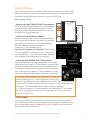
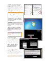
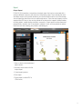
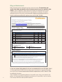
USER MANUAL AND
F R E Q U E N T LY A S K E D Q U E S T I O N S
dyonicsplan.com
DYONICS™ PLAN
Hip Impingement Planning System
PLAN Begins Here
The revolutionary way to visualize FAI and develop
a patient-specific preoperative plan to correct it.
Get Started with the PLAN
The revolutionary way to visualize FAI and develop
a patient-specific preoperative plan to correct it.
Table of Contents
Introduction2
System Requirements
4
Using the Software
5
Getting Started
6
MacBook Pro®6
Windows® PC 8
License Activation
9
Loading CT Scans
10
Functionality Overview
12
Landmarks
Planning
Report
12
15
19
Frequently Asked Questions
20
General Hardware/Software
Billing and Reimbursement
CT Scans/Protocol
Loading CT Scans
Installation, Account Setup and License Activation
Landmarks
Planning
Output/Report
Clinical Studies, Research and Evidence
Research and Evidence-based Support
20
22
23
27
28
29
30
34
34
34
Ordering Information
back cover
1
Introduction
Developed by surgeons for surgeons.
A comprehensive and fully interactive solution for FAI identification and correction planning,
the DYONICS™ PLAN Hip Impingement Planning System provides a deeper understanding of
hip impingement than what is possible with standard imaging tools. Designed in conjunction
with the following surgeons, the DYONICS PLAN System is the revolutionary way to visualize
FAI and develop a patient-specific preoperative plan to correct it.
“DYONICS PLAN can help to avoid pitfalls of radiographs due to differences in pelvic tilt, as
pelvic tilt has an effect on acetabular version, crossover sign, and ROM.”
Asheesh Bedi, MD
“DYONICS PLAN will substantially raise the bar on the standard of what can be accomplished
in patients with symptomatic FAI.”
J.W. Thomas Byrd, MD
“Performing impingement surgery in the hip without the plan [DYONICS PLAN] is analogous
to putting in a total knee without jigs. The plan [DYONICS PLAN] takes the guesswork out of
every case.”
Bryan Kelly, MD
“DYONICS PLAN can be used to determine virtual ROM with specific activities and the
anticipated improvement in this motion with different surgical corrections to individualize
the surgical plan to the patient’s needs.”
Christopher Larson, MD
2
Benefits of using the DYONICS™ PLAN
Hip Impingement Planning System
Featuring interactive planning tools, DYONICS PLAN identifies areas and degree of hip
impingement between the pelvis and femur; it automates measurements and provides you
with range-of-motion (ROM) simulations that allow the development of a presurgical resection
plan based on a patient’s unique morphology, activity requirements and your clinical judgment.
In addition, the PLAN System utilizes a low-dose CT scan protocol which requires 50% less
radiation than standard options.1
Establish strategies with 3D femoral
resection planning
• Navigate between original morphology, correction
plan and resected morphology
• Correction plan is generated automatically
based on alpha angles around the clockface
• Resection strategy is easily modified with
built-in planning tools
Develop solutions with 3D acetabular
resection planning
• Generate automated measures including: center edge
angle, crossover sign, version and percent acetabular
coverage of the femoral head
• Develop resection plan either based on impingement
identified by dynamic ROM assessment or with stored
coverage data from 400 normative asymptomatic hips
Visualize the hip in standard radiographic
positions with virtual fluoroscopy and X-ray
• Virtual fluoroscopy displays location of maximum
alpha angle, which can facilitate recreating the same
view intraoperatively
• Virtual radiographic images may reduce the need for
additional X-rays
Identify areas of conflict, including subspine
impingement,2 with dynamic ROM analyses
• Identify impingement areas manually or
automatically with predefined motion patterns
• Locate abnormal anatomy associated with
subspine impingement
•C
ustomize resection plan based on sports-specific
motion analyses
• Visualize projected, improved ROM as a result of resection plan
1. CT Protocol Report, HIPS. Document number 15001984, 2013. Data on file at Smith & Nephew.
2. Hetsroni I, Larson CM, Dela Torre K, Zbeda RM, Magennis E, Kelly BT. “Anterior Inferior Iliac Spine Deformity as an Extra-articular Source for Hip Impingement:
A Series of 10 Patients Treated with Arthroscopic Decompression.” Arthroscopy 28, no. 11 (Nov.2012):1644–53.
3
System Requirements*
DYONICS™ PLAN requires a powerful graphics card to complete the three-dimensional
rendering of the CT scans, and to complete the resection plan. The performance of DYONICS
PLAN software has been validated on the following systems, with the listed specifications:
Dell Precision M4600
Laptop Workstation
•Ethernet port and/or Wi-Fi certified
with connectivity
• Processor Unit: Intel Core i7
2860 QM, 2.5 GHz, 8 MB, QuadCore
•Keyboard
• RAM: 8 GB
• Screen: 1920 x 1080 resolution
• Hard Drive: 500 GB, 7200rpm
Minimum PC Requirements:
• Graphics Card: NVIDIA Quadro 2000M
• Processor Unit: 1.73 GHz, 8 MB, QuadCore
• Operating System: Windows® 7
Professional, 64-bit or Windows 8
Professional, 64-bit
• RAM: 4 GB
• 2 USB 2.0 or 3.0 ports
• Screen: 1920 x 1080 resolution
• Hard Drive: 500 GB
• DVD-ROM drive
• Graphics Card: 1 GB NVIDIA Quadro FX
1800 M, 45 W
• Ethernet port and/or Wi-Fi certified
with connectivity
• Operating System: Windows 7, 64-bit
• Keyboard
• Mouse with three buttons
and a scroll wheel
HP ZBook 15
(Product ID F2P53UT#ABA)
• Processor Unit: Intel Core i7-4700MQ
2.4 GHz, 2.4 GHz, 6 MB, QuadCore
Apple MacBook Pro Requirements:
• MacBook Pro 2.3 GHz QuadCore
Intel Core i7
• RAM: 16 GB
• Hard Drive: 512 GB
• Graphics Card: NVIDIA GeForce GT 750M,
2 GB memory
• RAM: 8 GB
• Display resolution: 2880 x 1800
(supports 1920 x 1080)
•Screen: 1920 x 1080 resolution
• USB drive
•Hard drive: 500 GB, 7200rpm
• Wireless connection to Internet
•Graphics Card: NVIDIA Quadro K1100M,
2 GB
• External CD/DVD drive
•Operating System: Windows 7
Professional, 64-bit
•4 USB 2.0 or 3.0 ports
•DVD-ROM drive
4
•Mouse with three buttons
and a scroll wheel
• Mouse with three buttons
and a scroll wheel
• Operating System: Dual boot OS X
Mavericks Version 10.9/ Windows 8
Professional 64-bit (OR) Dual boot OS X
Mavericks Version 10.9/ Windows 7
Professional 64-bit
*The aforementioned System Requirements have been validated by Smith & Nephew through the following: Software validation 15001857.
Data on file at Smith & Nephew. ZBook validation report 15002370. Data on file at Smith & Nephew. MacBook validation report 15002629.
Data on file at Smith & Nephew. Future system requirement updates will be available at dyonicsplan.com.
Using the Software
Thank you for your interest in the DYONICS™ PLAN Hip Impingement Planning System. What
follows are instructions, guidance and answers to common questions relating to the system.
This booklet is designed to help you get the most out of DYONICS PLAN.
Before getting started
CT Scan Protocol
1. Review the low-dose3 DYONICS PLAN CT Scan Protocol
A CT Scan Protocol document is obtained from a Smith & Nephew
sales representative or by visiting dyonicsplan.com. Once
received, the protocol should be reviewed in its entirety with
the radiologist or imaging department.
Image Acquisitions
Image PLAN
Reconstructions
DYONICS™
Image Acquisitions
Bilateral Pelvis
Hip Impingement Planning System
Axial Scanning Range:
ASIS
CT ScanImage
Protocol
Reconstructions
Start: Midpoint between the anterior inferior iliac spine (AIIS)
and anterior superior iliac spine (ASIS)
End: 30 mm below lesser trochanter
Start
Reconstruction 1: Bilateral Pelvis
Image Reconstruction
Parameters
FOV Diameter: 500 mm. Use same X and Y centers for both
pelvis and knee scans based on a single coronal scout
AIIS
Collimation Thickness: Minimum slice/row thickness available
Slice Thickness: 2.0–2.5 mm
Pitch: As close to 1.0 as possible
Reconstruction Interval: 2.0–2.5 mm
Tube Voltage: 120 kV
Reconstruction Kernel/Algorithm:
Tube Current Time Product:
End
Lesser Trochanter
Soft Tissue: Siemens: B30,
GE: Standard, Toshiba: FC03,
Philips: A, or equivalent*
Small patients: 100 mAs
Medium patients: 150 mAs
Or
Large patients: 200 mAs
Figure 1. Bilateral pelvis
Bone Tissue: Siemens: B70, GE: Bone,
Toshiba: FC30, Philips: C, or
equivalent*
Or other standard guidelines, if required by your department
or institution.*
Data Format: Axial DICOMs (no MPRs)
Matrix Size: 512 x 512
Bilateral Knees
Figure 3. Bilateral pelvis reconstruction field of view
Axial Scanning Range:
Start: 40 mm proximal to knee joint line.
End: Knee joint line (Scan must cover epicondyles
and
Reconstruction
posterior condyles in their entirety)
Start
2. Qualify a CT scan with Smith & Nephew
In order to ensure that your CT scans will work properly with
the PLAN software, the radiologist/technician must send one
anonymized CT scan, per the CT Scan Protocol guidelines,
to Smith & Nephew for qualification purposes.
End
Joint
Line
Figure 2. Bilateral knees
2: Bilateral Knees
FOV Diameter: 500 mm. Use same X and Y centers for both
pelvis and knee scans based on a single coronal scout
Image Reconstruction
Parameters
Collimation Thickness: Minimum slice/row thickness available
Slice Thickness: 2.0–2.5 mm
Pitch: As close to 1.0 as possible
Reconstruction Interval: 2.0–2.5 mm
Tube Voltage: 120 kV
Reconstruction Kernel/Algorithm:
Tube Current Time Product:
Soft Tissue: Siemens: B30,
GE: Standard, Toshiba: FC03,
Philips: A, or equivalent*
Small patients: 100 mAs
Medium patients: 150 mAs
Or
Large patients: 200 mAs
Or other standard guidelines, if required by your department
or institution.*
10601148 Rev. A
Bone Tissue: Siemens: B70, GE: Bone,
Toshiba: FC30, Philips: C, or
equivalent*
Data Format: Axial DICOMs (no MPRs)
Matrix Size: 512 x 512
*CT scan compatibility with DYONICS PLAN has only been validated for the specified parameters.
DYONICS™ PLAN
CT Scan Protocol
3
10601148 Rev. A
Figure 4. Bilateral knees reconstruction field of view
*CT scan compatibility with DYONICS PLAN has only been validated for the specified parameters.
4
10601148 Rev. A
DYONICS™ PLAN
CT Scan Protocol
Qualification CT scans should be sent to:
[email protected]. Please include
“CT Scan Qualification” in the subject line. If it is necessary to
mail the qualification CT scan, please contact your authorized
Smith & Nephew sales representative for instructions.
3. Use the low-dose DYONICS PLAN CT Scan Protocol
Once your qualification scan is deemed compliant, you may begin
collecting new scans using the CT Scan Protocol in conjunction with
any recommendations you receive from Smith & Nephew. You will
have a 30-day window to use the tool upon activation of the evaluation. To optimize this trial period, it is recommended that you have
several scans ready and waiting before an evaluation is requested.
Note: Request that the imaging center provide one CD/DVD for each
patient containing only the CT series required for DYONICS PLAN
(refer to CT Scan Protocol document). Additional images on the CD/DVD, not required by
DYONICS PLAN, will add a significant amount of time to the CT copy/upload process for
each patient. The initial download process requires some time and power.
Note: Whenever possible, it is recommended that you implement the CT Scan Protocol
with only one imaging facility to help ensure the consistency of CT Scans that will be
used with DYONICS PLAN.
4. Choose a laptop
The laptop you choose to use with the DYONICS PLAN software must meet the minimum
system requirements listed on the previous page to function properly. If preferred, you can
discuss the possibility of renting a laptop with your Smith & Nephew sales representative
to use with the DYONICS PLAN System.
3. CT Protocol Report, HIPS. Document number 15001984, 2013. Data on file at Smith & Nephew.
5
Getting Started
Apple MacBook Pro Users
Before installing DYONICS™ PLAN on MacBook Pro, please ensure that you are in
“boot camp” mode and running Windows 7 or 8. More information on this subject can
be found at: https://www.apple.com/support/macbookpro/bootcamp/.
Steps for installing the DYONICS PLAN Hip Impingement Planning System
on a MacBook Pro using Boot Camp
1. Purchase a MacBook Pro laptop that meets the requirements for DYONICS PLAN
(note the requirement for an NVIDIA graphics card).
2. Purchase Windows 7 or Windows 8, Professional, 64-bit.
– If installing Windows from a DVD, you will also need an Apple SuperDrive
(external CD/DVD drive).
3. Install Windows using the Boot Camp
Assistant application (from the Other
folder in Launchpad).
– Follow the Boot Camp Installation
& Setup Guide (access the manual via
http://www.apple.com/support/bootcamp/)
to create a Windows partition and then
start the Windows installer.
Note: When prompted to create a Windows partition, create a partition of at least 150 GB.
Troubleshooting Tips
(in addition to those provided in the Boot
Camp Installation & Setup Guide)
If you receive the error message during
installation of Windows, “Windows could not
update the computer’s boot configuration.
Installation cannot proceed.”:
• Restart the Mac into the Mac
operating system
• Launch Boot Camp Assistant and remove the Windows partition
• Reset the NVRAM on your Mac
– To reset the NVRAM, first shut down your Mac
– Locate the following keys on the keyboard: Command, Option, P, and R
– Turn on the computer
– Press and hold the Command-Option-P-R keys before the gray screen appears
– Hold the keys down until the computer restarts and you hear the startup sound
for the second time
– Release the keys
• Launch the Boot Camp Assistant and try the Windows installation again
6
If the keyboard and mouse are unresponsive during the Windows installation:
• Restart the Mac into the Mac operating system
• Create a new administrator user account
• Launch Boot Camp Assistant and remove the Windows partition
• Restart Boot Camp Assistant and reinstall Windows
Note: To switch between operating systems, hold the Option key while you start up your
Mac to manually select the operating system.
4. Once Windows is installed, start up your Mac in Windows and follow the “Getting Started”
steps in this guide to install DYONICS™ PLAN.
After PLAN Installation
5. S
et the screen resolution to 1920 x 1080
– Go to Control Panel > Hardware and
Sound > NVIDIA Control Panel > Change
Resolution, and select 1920 x 1080.
6. Modify the contents of the “application
ExtConstants.ini” resource file.
– Access the folder where DYONICS PLAN
is installed. The default location is
C:\Program Files (x86)\DYONICS PLAN.
– Select the Resources folder and open the
“applicationExtConstants.ini” text file with a text editor (e.g., Notepad)
– Modify “applicationExtConstants.ini” to the following:
[Driver Version]
first=0
second=0
third=0
– Save “applicationExtConstants.ini”
Note: You may need to create a copy of
“applicationExtConstants.ini” on the Desktop
in order to resave it before replacing the
old version in the Resources folder.
7. Launch the DYONICS PLAN application.
7
Steps for installing the DYONICS™ PLAN Hip Impingement Planning System
on the Windows OS
IMPORTANT Before downloading the DYONICS PLAN software, ensure that the laptop you
choose to use is connected to a high-speed Internet line and the power cord is plugged in,
as the initial download process requires some time and power.
Once you’ve purchased a licensing option for the DYONICS PLAN Hip Impingement Planning
System, the following steps will help guide you through the download and installation process.
It is recommended that your Smith & Nephew sales representative assist you with this process
to ensure a smooth integration.
Note: More information on installing and using the PLAN system is available from
Smith & Nephew Digital Communications at YouTube.com
1. An email is sent from Smith & Nephew
containing a software download link,
the license ID and the license password
associated with your subscription.
Please retain a copy of this information
for your records.
If installing from a CD*
If installing the software from a CD, load the
CD and then, to install the software, doubleclick the DYONICS PLAN icon that appears.
The Instructions for Use (IFU) document is also
available on the CD and it is recommended
that you save the IFU file for future reference.
Proceed to step 6.
2. Click on the link provided in the email.
This will direct you to a Software Downloads
page where you will be asked to log in to
your account by entering your license ID
in the Login Name or ID field and your license
password in the Password field.
3. After the initial login, you are automatically
directed to a second Software Downloads
page that shows all the licenses and/or tokens
you’ve purchased, including those purchased
in the past. Click the Download button
associated with the software license you’d
like to activate.
4. From the next Software Downloads page
you are able to access the DYONICS PLAN
Instructions for Use (IFU) document, the DYONICS PLAN CT Scan Protocol document,
and the DYONICS PLAN Hip Impingement Planning System software download.
8
Note: It is recommended that you download and save the IFU document for future
reference. The CT Scan Protocol and other useful information, including an instructional
video by chapter, can be found at dyonicsplan.com.
*Currently available in Japan only.
5. Click the Software download button
to begin downloading the DYONICS™
PLAN setup file and follow the steps in the
popup windows that appear. The download
process should take approximately 6-10
minutes, depending on Internet speed, when
downloading from the email link.
Note: If a certified NVIDIA video driver
warning pops up, click “OK” and continue
the installation. If after doing so the
software does not work properly or if
you are unable to upload CT scans after
installation, contact Smith & Nephew for
assistance at Dyonicsplan.Techsupport@
smith-nephew.com.
Double-click to open
6. Installation. Locate the DYONICS PLAN
setup file (executable) you installed in step 5.
Click on it and follow the onscreen installation
instructions.
7. When the installation is complete, a
DYONICS PLAN icon will appear on the
desktop. Double-click the icon to open
the program.
Note: Your system may automatically
restart immediately after installation is
complete.
Activate Your License
8. If you are a first-time user, a
new user profile must be created
before you can begin using the
software. Click “First time user?”
from the Login screen, enter the
required information, and click
“OK”. Required information is
indicated by a red asterisk.
9. Be sure to agree to the end
user license agreement. Then
activate your new license by entering the
license ID and password provided to you in
the email from customer service.
Your DYONICS PLAN Hip Impingement
Planning System license is now active!
9
Load CT Scans
Reminder: An initial CT scan must be qualified by Smith & Nephew. Please refer to
item 2 on page 5.
10. From the Home page you are able to upload patient CT scans by clicking the
New CT button.
IMPORTANT It is recommended that your imaging center provide the CT data for each
patient on a separate CD/DVD. The total file size of the DICOM folder is typically less than
500 MB.
Note: It is recommended that patient CT images are first copied from the CD/DVD to
the laptop hard drive. A staff member can assist with the transfer of patient data. After
completing this process, CT scans are accessed from their location on the computer’s
hard drive.
11. You will be directed to the Load New Case tab where you are able to locate and
upload CT scans in DICOM format from the hard drive and within the patient selection page.
Patient information entered during the CT scan process is automatically populated at the
right side of the Patient Selection page.
12. When finished uploading CT scans, click “OK” on the Patient Selection page.
You will then be directed to the CT Series Identification page where DYONICS™ PLAN
will automatically identify the required series: Bilateral Hips, Bilateral Knees and Right/Left
Hip. After all series have been identified, click “OK”.
Note: If a series is not automatically
identified, drag and drop the
unidentified series from the Input
Series box to the appropriate
Identified Series box below.
10
13. From the Home page, double click to open
the case you wish to work on. This will take you
to the Landmarks tab which is the first step of the
DYONICS™ PLAN System planning process.
14. From the Landmarks tab, DYONICS
PLAN will attempt to automatically adjust
the center of the femoral head. It is not
uncommon to manually adjust the center
of the femoral head based on the patient’s unique
anatomy or for any other reason. Please refer to
the screenshots. Click the Help button to assist you
throughout the process.
You should now be well on your way to fully utilizing the DYONICS PLAN Hip Impingement Planning
System. Throughout your usage, the Help button can
assist you with each step of the planning process
and the Instructions for Use document (IFU) can also
be a valuable resource. In addition, an instructional
video, broken down by chapters such as Landmark Identification, Femur Planning, Acetabular
Planning and Range of Motion Analysis, is available at dyonicsplan.com.
11
Functionality Overview
The DYONICS™ PLAN Hip Impingement Planning System features a variety of interactive
tools and planning steps designed to assist you in developing viable solutions to address
femoroacetabular impingement (FAI). The following diagrams are provided to introduce you
to the functionality of the PLAN System and help you become familiar with what is available
through the software.
Landmarks
Femoral Head
Using the loaded CT scans, the PLAN System automatically calculates a best fit sphere to the
patient’s femoral head. These and other automatic defaults are modifiable at every step of
the planning process.
2
1
5
4
3
6
7
Femoral Head
1. Coronal CT image display
12
2. Axial CT image display
5. F emoral Head Adjustment – drag orange
circle to adjust femoral head center
3. R
eturn to slice containing femoral
head center
6. Femoral Head Adjustment – drag circle
border to adjust femoral head diameter
4. Navigation Slider – use to navigate
CT slices
7. Return – resets to DYONICS PLAN System
default femoral head calculation
Femur
The PLAN System automatically identifies key femoral anatomic landmarks, renders 3D
femoral models, creates clockface reference and identifies 3D anatomic femoral axes.
PLAN also calculates neck-shaft and neck version angles.
3
2
1
4
5
6
7
8
Femur
1. Drag “12” to change clockface reference
position
5. S
elect thumbnail to modify neck axis
2. Orange line indicates location of CT
slice on 3D rendering
7. Select thumbnail to modify shaft axis
3. C
T Slice View – adjustable with
clock-face tool
6. Select thumbnail to modify knee axis
8. D
isplay Area of neck-shaft and neck
version angles
4. Drag orange circles to modify landmarks
13
Landmarks continued
Pelvis
With default calculation of acetabular inclination and version shown, DYONICS™ PLAN allows
for the manual adjustment of acetabular rim points (if necessary) and pelvic orientation,
specifically pelvic tilt, if the patient was malaligned in the CT scanner.
2
1
3
4
5
6
7
8
Pelvis
1. Drag “12” to change clockface
reference position
2. X-ray Image Area – shows
simulated pelvis X-ray image
3. C
ontrol Slider – adjusts default pelvic tilt
generated by DYONICS PLAN
(sets baseline for all measurements)
4. Control Slider – adjusts default pelvic
rotation generated by DYONICS PLAN
14
5. C
ontrol Slider – adjusts default
pelvic horizontal axis generated by
DYONICS PLAN
6. Select this thumbnail to modify
the pelvis orientation
7. Select this thumbnail to modify
the acetabular rim points
8. D
isplay Area of global acetabular
inclination and version angles
Planning
Femur
The DYONICS™ PLAN System has several features designed to help you plan your approach. With
DYONICS PLAN you are able to create a 3D femoral (cam) resection plan and generate a 3D
correction plan based on alpha angles around the clockface. Built-in planning tools allow you
to modify your resection strategy, and maximum 3D alpha angles are automatically calculated.
2
3
1
4
5
6
7
Femur
1. Topographical map illustrates depth of
default correction
5. D
rag grey circles to modify extent
of correction
2. Toggle between original, correction
plan and resected morphology
6. Display of max alpha angle values
and clockface location
3. A
lpha angle value for current CT slice
7. Display of percentage neck resection
(safety measure)
4. Drag orange circles to modify
correction plan
15
Planning continued
Acetabulum
Automated measures can be generated for center edge angle, crossover sign, version and
percent acetabular coverage of the femoral head. A 3D acetabular (pincer) resection plan can
be created or a resection plan can be developed based on impingement from dynamic ROM
assessment. Additionally, a resection plan can be developed based on stored coverage data
from 400 normative asymptomatic hips.
3
1
5
4
2
7
6
Acetabulum
1. Topographical map illustrates depth
of default correction
5. T ab used to create a local acetabular
correction and/or modification
2. Toggle between original, correction
plan and resected morphology
6. Control Slider adjusts acetabular
correction using the normative data
3. T abs display key acetabular
measurements
7. Select to create resection based on
blue impingement from ROM step
4. Black dots correspond to patient rim
points; white line and grey band
correspond to average and standard
deviation from 400 normative hips
16
Range of Motion (ROM)
With this planning feature you are able to perform dynamic ROM assessments; identify
impingement areas, manually or automatically with predefined motion patterns; and locate
abnormal anatomy associated with subspine impingement. Resection plans can be customized based on sports-specific motion analyses, and projected improved ROM, as a result of
the resection plan, can be visualized.
4
2
5
1
3
6
7
Range of Motion (ROM)
1. Blue shading indicates areas of
impingement
5. C
reate or play custom motions
(e.g., sports-specific motions)
2. Toggle between original, correction
plan and resected morphology
6. Display of tabulated pre- and postrange-of-motion values
3. C
ontrol Sliders manually change
the position of the hip
7. Buttons return hip to zero and erase
blue areas, respectively
4. Select and play preset motions
(common clinical exam motions)
17
Planning continued
X-ray
X-ray planning allows you to view and assess virtual X-ray images and display the location
of maximum alpha angle, which can facilitate recreating the same view intraoperatively.
In addition, virtual radiographic images may reduce the need for additional X-rays,
subsequently limiting the patient’s exposure to more radiation.
1
2
3
4
X-ray
1. Toggle between original, correction plan
and resected morphology
2. Virtual X-ray and fluoroscopic image area
3. C
ontrol Sliders manually change the
position of the hip
4. Preset radiographic views
5. H
ip position required to visualize max
alpha angle
18
5
Report
Output Report
DYONICS™ PLAN provides a comprehensive output report that can be customized with a
variety of different measures and views from the planning steps. These include the resection depth at each clock position based on your resection plan and the virtual fluoroscopy
view and position where the maximum alpha angle occurs. Since the output reports can be
exported into PDF format, they can be viewed on any device that supports Adobe Reader®,
including tablets, mobile devices and Mac® computers. Output reports can be referenced
preoperatively, viewed in the OR or placed in a patient’s chart, and can provide an educational resource when dealing with patients and colleagues.
4
5
1
3
2
Output Report
1. Save or select customized output
report content
2. Manually select content for the
output report
3. O
utput report preview
4. Print report
5. E xport report in either PDF or
HTML format
19
Frequently Asked Questions
General Hardware/Software Questions
Q. Will DYONICS™ PLAN work on my laptop?
A. Compare your laptop’s specifications to the minimum requirements posted on page 4 or
at dyonicsplan.com. The absolute requirements you’ll want to check for are the inclusion of a
NVIDIA Quadro graphics card (>1 GB memory) and a 1920 x 1080 screen. The PLAN System
requires a powerful graphics card to generate the 3D renderings of the CT scans and to
complete the resection plan.
Q. If I use a higher-end computer than what is specified, will the copying of CT files be
accomplished more quickly, and will DYONICS PLAN run faster in general?
A. Laptops with relatively high performance specifications have been specifically selected and
tested for use with the DYONICS PLAN System. When using these or comparable laptops, it
should require approximately five minutes to copy CT scans from a CD and another ~20 seconds
to load them into PLAN. A more powerful computer may speed up this process slightly, but the
real limiting factor is the time it takes any computer to copy files from a CD. It is recommended
that a laptop validated by Smith & Nephew is used to run the PLAN System. Please refer to
page 4 for minimum system requirements.
Q: Can I install DYONICS PLAN on a Mac laptop?
A: Yes, DYONICS PLAN can be installed on a MacBook Pro laptop that meets the minimum
computer specifications (i.e., one with an NVIDIA graphics card). You will need to install
Windows on the MacBook Pro using the Boot Camp Assistant application. DYONICS PLAN
can then be installed on the Windows partition after some additional setup steps.
Q: What type of Mac laptop do you recommend for use with DYONICS PLAN?
A: Please refer to the system requirement specifications on page 4.
Q: Will running DYONICS PLAN on a Mac (with Windows installed via Boot Camp) affect the
performance of the PLAN software?
A: No, DYONICS PLAN will run exactly the same whether installed on a Windows PC or a Mac
computer that meets the specified requirements. If the Mac computer does not have an optical
CD/DVD drive, you may need to use an external Apple CD/DVD SuperDrive to import CT
exams from CD/DVD obtained from your radiology department.
Q. When I try installing PLAN on the laptop, a pop-up warning states that the certified NVIDIA
video driver cannot be installed?
A. This is normal. Simply click “OK” and continue the installation. If after doing so, the software
does not work properly or if you are unable to upload CT scans after installation, please
contact Smith & Nephew for assistance through the resources listed on the back cover of
this booklet.
20
Q. Does the PLAN computer need to be networked with our PACS to access CT scans?
A. No, the PLAN software does not access images via PACS. In fact, the PLAN laptop
does not need to be networked at all to function properly. All media must be transferred
and uploaded manually.
Q. Will patient information ever leave my PLAN computer?
A. No. The CT and patient demographic data is never transmitted anywhere and does not
need to ever leave the PLAN computer. If you are using a Smith & Nephew computer for the
evaluation, we ask that you remove all patient data (including CT scans) before returning the
laptop to Smith & Nephew.
Q. How do I remove patient data from the laptop?
A. There are three main sources of patient data that you need to remove:
1. PLAN cases in your account – To remove your PLAN cases, delete your user account.
On the PLAN Login screen, enter the password for your account and select the “Delete
User” icon on the right navigation panel. All data for this account will be deleted.
2. CT scans on the desktop/hard drive – If you
copied CT scans to the desktop or hard drive,
locate the CT scans and delete them.
3. Exported output reports on the hard drive –
To delete any exported output reports, delete all
reports contained in the “C:\Case Report” folder.
If you’ve exported reports to another location on
the hard drive, delete those also.
Delete User
21
Billing and Reimbursement
Billing and reimbursement protocols vary from country to country. The questions and
answers that follow are specific to the US and are meant to serve as a guide for other
nations. The 2014 Medicare Coding and Payment Reference Sheet below can serve as
a guide to help you determine what is best for your practice or institution. For specific
geographic payment information, visit www.smith-nephew.com/reimbursement or
contact [email protected] or call +1 888-711-9903.
DYONICS™ PLAN Reimbursement Guide
Hip Impingement Planning System
2014 Medicare Coding and Payment Reference Sheet
Visit the site at www.smith-nephew.com/reimbursement to obtain specific geographic payment information.
Current Procedural Terminology (CPT) is copyright 2014 American Medical Association. All Rights Reserved. No fee schedules, basic units, relative values,
or related listings are included in CPT. The AMA assumes no liability for the data contained herein.
Note: Private payer coverage and payment policies will vary. Payers should be consulted in regard to their specific policies. Most payers closely monitor
Medicare fee schedules.
Common Imaging Coding
CPT codes are used by hospital outpatient departments (OPPS), ambulatory surgery centers, Independent Diagnostic Testing
Facility (IDTF), and physicians to describe professional services and procedures. Based on CY2014 Medicare Imaging Fee Schedule
national payment rates are as follows:
CPT
Description
Physician
IDTF
72192
CT pelvis w/o dye
$152.61
$76.30
OPPS
$181.62
72192-TC
Technical Component
$97.44
$48.72
$126.45
72192-26
Professional Component
$55.17
$27.58
$55.17
73700
CT lower extremity w/o dye
$193.08
$96.54
$178.04
73700-TC
Technical Component
$141.50
$70.75
$126.45
73700-26
$51.58
$25.79
$51.58
76377
Professional Component
3D rendering, requiring image postprocessing on an independent
workstation
$84.18
N/A
**
76377-TC
Technical Component
$44.06
N/A
**
76377-26
Professional Component
$40.12
N/A
**
Report code 76377 in addition to the base imaging procedure.
** Packaged service/item; no separate payment made.
ICD-9-CM and ICD10 Cross walk
ICD9
719.45
719.85
Description
Pain in joint, pelvic region and thigh
Other specified disorders of pelvic joint
ICD10
M25.559
M25.859
Description
Pain in unspecified hip
Other specified joint disorders, unspecified hip
Common Modifiers
In addition to selecting appropriate CPT codes, providers should pay attention to the use of modifiers. A modifier indicates that a
service or procedure was altered by specific circumstances, but not changed in its definition or code.
Modifier Descriptor
-26
Professional Component
Technical component. Under certain circumstances, a charge may be made for the technical component alone. Under those circumstances the
technical component charge is identified by adding modifier 'TC' to the usual procedure number. Technical component charges are institutional
charges and not billed separately by physicians. However, portable x-ray suppliers only bill for technical component and should utilize modifier
-TC
TC. The charge data from portable x-ray suppliers will then be used to build customary and prevailing profiles.
When billing without a modifier, this means the services performed included both components.
Medicare reimbursement for diagnostic imaging procedures is comprised of a professional component, the amount paid for the physician’s
interpretation and report, and a technical component, the amount paid for all other services (including staffing and equipment costs).
When combined and paid to the same individual or entity, this amount is often referred to as the total or global reimbursement.
This coding list is not all-inclusive and is not intended to represent all coding options. Coding of diagnosis/procedure code(s) is dependent on documentation in the patient's medical record. The information
in this document is provided as a guide for coding procedures and services involving the Smith & Nephew DYONICS PLAN products. It is not intended to increase or maximize payer reimbursement by any
payer. Providers assume full responsibility for all reimbursement decisions or actions. We strongly suggest that you consult your organizations with regard to local coverage and reimbursement policies.
™Trademark of Smith & Nephew. Registered US Patent and Trademark Office
Q. How are surgeons billing patients for the costs associated with the use of DYONICS™ PLAN?
A. Please refer to the DYONICS PLAN reimbursement chart above for suggested CPT codes
to use with PLAN. Contact [email protected] or call +1 888-711-9903
for additional information.
22
Smith & Nephew cannot provide guidance on how to bill or pass along costs directly to the
patient. It is recommend that you reference how other costs at your facility, such as crutches,
Game Ready and PRP are directly billed to patients.
Q. How do I code for the different required CT series?
A. Please refer to the DYONICS™ PLAN reimbursement chart for suggested CPT codes.
Contact [email protected] or call +1 888-711-9903 for additional
information. It is recommended that you speak with other surgeons using DYONICS PLAN
for tips on how it was implemented at their facility.
Q. What are my options if insurance carriers are denying coverage for the bilateral hip series?
A. Please refer to the DYONICS PLAN reimbursement chart for suggested CPT codes.
Contact [email protected] or call +1 888-711-9903 for additional
information. It is recommended that you speak with other surgeons using DYONICS PLAN
for tips on how it was implemented at their facility.
CT Scans/Protocol
Please be advised that the CT exam must adhere to the requirements specified in the
CT Scan Protocol document. If it does not fully comply with these protocol requirements,
DYONICS PLAN may not be able to load the CT exam, or it may compromise the validity
of the analysis. If the CT exam is incomplete, DYONICS PLAN may fail to compute some
anatomic measurements.
Acquisitions
Perform only two acquisitions: pelvis and knees. Use the same frame of reference for both
acquisitions, i.e., from the same scout view.
Required Scout/Topograms
For the acquisitions, obtain each of the following scout/topograms:
• AP/Coronal
• Lateral/Sagittal
Required Reconstructions
Create three or four reconstructions including the pelvis, the knees and the right and/or
left unilateral hips.
The following reconstruction series must be included in the exam:
1. Bilateral axial pelvis reconstruction
2. Bilateral axial knees reconstruction
3. Unilateral axial right hip reconstruction
4. Unilateral axial left hip reconstruction
You must also include the AP/Coronal and Lateral/Sagittal scout views in the exam.
Note: For the unilateral hip reconstruction(s), do not perform a separate acquisition/study
for each hip side of interest. Instead, generate the unilateral hip reconstruction(s) from
the full pelvis acquisition/study.
23
Q. What CT series are required for use with DYONICS™ PLAN?
A. Please review the CT Scan Protocol document for complete CT scan requirements.
The following series will need to be included on the CD/DVD provided to the surgeon.
Thickness (mm)
Spacing (mm)
Convolution Kernel
FOV (mm)
Bilateral Hips
2.0–2.5
2.0–2.5
Soft tissue
500
Bilateral Knees
2.0–2.5
2.0–2.5
Soft tissue
500
Unilateral Hip
<1.25 (min. available)
0.5–0.75
Soft tissue
<250
Q. Can I include extra CT series (such as sagittal and/or coronal reformats) in the CT exam?
A. Yes, as long as the CT series required by PLAN are included as part of the CT exam. You may
perform additional series as required by your imaging center but it is recommended that you
only include the required PLAN CT series on the CD/DVD provided to the surgeon as additional images will add a significant amount of time to the CT upload process for each patient.
The total data size on a CD/DVD should be less than 500 MB.
Q. Can I adjust the tube current/dose values or use the automatic current modulation feature
on my CT scanner?
A. DYONICS PLAN software has only been validated for use with the tube current values
specified in the CT Scan Protocol. Any change of parameters outside the specified ranges
may lead to problems when processing CT scans in the DYONICS PLAN software.
Additionally, it is recommended that you do not use the automatic current modulation
function on your CT scanner as this has been shown to exhibit reduced image quality
for the cortical bone layer of the femoral head.
Q. What is the radiation dose?
A. The radiation dose for the PLAN CT Protocol was quantified using an anthropomorphic
phantom. The dose-length product was measured using the PLAN CT Protocol and the GE
factory default pelvis CT protocol applied to the full pelvis. The results demonstrate that the
radiation dose of the PLAN CT Protocol is less than 50% of the standard GE factory default.
Pelvis
DYONICS PLAN CT Protocol
GE Factory Default
Literature Reference*
308.6 mGY-cm
678.7 mGY-cm
648.7 mGY-cm
Knee
DYONICS PLAN CT Protocol
GE Factory Default
Literature Reference*
166.8 mGY-cm
331.3 mGY-cm
359.9 mGY-cm
Note: for comparison of the above dose-length products with other imaging modalities, a
pelvis and knee weighting factor can be used to convert the above values to effective dose.
*Biswas D., Bible JE., Bohan M., Simpson AK., Whang PG., Grauer JN., Radiation exposure from musculoskeletal computerized tomographic
scans, J Bone Joint Surg Am., August 2009, 91(8):1882-9.
24
Q. Will my facility’s CT scanner work for DYONICS™ PLAN?
A. It is recommend that you review the CT Protocol to ensure all specifications are met.
Research has shown that nearly all CT scanners currently on the market are compatible
with DYONICS PLAN.
Q. Is it possible to execute the CT Protocol using helical sequencing?
A. Yes, helical sequencing is the standard mode of modern CT scanners. As long as
the specifications in the PLAN CT Protocol are met, the scanner is acceptable.
Q. Can my imaging center use automated dose reduction (or other similar automated dose
settings)?
A. No, the use of automated dose reduction settings is not recommended. Research has
shown that when these settings are used, quite often there is a lack of signal in the images
passing through the femoral head-neck junction. This results in “holes” in the femoral 3D
bone models. If you do choose to use automated dose reduction settings, please check the
resulting 3D bone models in PLAN to ensure that they are being produced without artifacts.
Q. Is my current CT protocol acceptable for DYONICS PLAN?
A. Smith & Nephew has validated a specific, low-dose CT protocol for use with DYONICS PLAN.
Please adhere to the PLAN CT Protocol guidelines to ensure that all requirements are met.
Q. Can CT scans be sent to Smith & Nephew to test for compliance with PLAN?
A. Yes, after reviewing the CT Scan Protocol in its entirety with your radiologist or imagining
department, please send an anonymized CT scan to Smith & Nephew for prequalification
of the scan to ensure compatibility with the PLAN software.
Q. Do I need to scan a phantom before starting with PLAN?
A. No, you do not need to perform a phantom scan to qualify your scanner. Since CT scanners
are more standardized than MRI scanners, this qualification step with a phantom is not required.
Q. Does my imaging center need to send every scan to Smith & Nephew (consistent with
the VISIONAIRE™ Knee process)?
A. No, anonymized scans should be sent for your first patient only. This allows Smith & Nephew
to check for compatibility, and after your scans are deemed compliant, you do not need to
send future scans. Once determined compliant, scans are sent directly from the radiologist
or imaging department to the surgeon using PLAN.
Q. Are there weight or Body Mass Index (BMI) recommendations for determining whether
a patient is “small,” “medium” or “large”?
A. While the DYONICS PLAN System does not set specific recommendations for determining
a patient’s size, it is recommend that you use the standard BMI definitions of small <25,
medium 25–30 and large >30.
25
Q. Do surgeons still request to have CT scans read by radiologists?
A. Yes, in most cases CT scans will continually be read by radiologists. Please be advised that
scans, not read by radiologists, could be considered “technical scans” and may not be
reimbursed. It is recommended that scans are read by a radiologist. Additionally, PLAN is
not meant to replace your normal diagnostic process; it is intended to provide a supplementary
tool for understanding and planning FAI correction specific to a patient’s unique pathology.
Q. How should the imaging center provide CT scans to the surgeon using DYONICS™ PLAN?
A. Most sites will send PLAN CT scans to the surgeon on a CD/DVD or USB stick, while other
imaging centers allow surgeons to download CT scans from a network connection using file
sharing software like Dropbox and Hightail.
Q. Can I include PLAN CT scans for more than one patient on a CD/DVD, or include additional
CT series that are not part of the DYONICS PLAN CT Protocol?
A. This is not recommended. It is preferable for each CD/DVD to contain only the CT scans
for a single patient and only the series required by DYONICS PLAN (as specified on the CT
Protocol). Additional CT data on the disc will significantly increase the time it takes to copy and
load onto the PLAN laptop. The CT information required by PLAN should easily fit onto a single
CD/DVD.
Q. Why am I receiving a pop-up window asking me to check the unilateral and bilateral CT
scan alignment on the Pelvic Landmark page?
A. This is most likely to occur if the bilateral and unilateral CT series are not created from the
same CT acquisition. For example, if the pelvic region of the patient is scanned twice to create
the bilateral and unilateral CT series, the two series are not necessarily aligned spatially as the
patient could have moved between scans. Repeat scanning increases the radiation exposure
so it is advisable to follow the instructions in the CT Protocol, which only require one pelvis
acquisition.
26
Loading CT Scans
Q. How long should it take to load a CT scan from a CD/DVD directly into PLAN?
A. If the CT scan contains only the required CT series from the PLAN CT Protocol, it should
take approximately 10-15 minutes to load the DICOM files from the CD/DVD directly into
PLAN. It is recommended that you first copy the CT scan DICOM files to the computer’s hard
drive. This should take approximately five minutes. Then, load the files directly into PLAN which
should take approximately 30 seconds.
Q. How can I speed up the process of loading CT scans from a CD/DVD to the
PLAN computer?
A. It is recommended that you copy the CT scan DICOM files from the CD/DVD to the
computer’s hard drive (i.e., a folder on the desktop) BEFORE uploading the images into PLAN.
This is the quickest way to load scans into the system.
Q. How long should it take to copy a CT scan from a CD/DVD to the computer’s hard drive?
A. If the CT scan only contains the required CT series from the PLAN CT Protocol, it should
take approximately five minutes to copy the DICOM files from the CD/DVD to the computer’s
hard drive.
Q. How long should it take to load a CT scan from the computer’s hard drive directly into PLAN?
A. If the CT scan contains only the required CT series from the PLAN CT Protocol, it should
take approximately 30 seconds to load the DICOM files into PLAN.
Q. Why isn’t DYONICS™ PLAN loading a CT series (from the CT Series Identification screen)
that is on the disc?
A. This is most likely due to noncompliance with the PLAN CT Protocol. Check the slice
thickness, spacing, FOV and scan length (z-length of anatomy scanned) to ensure compliance with the PLAN CT Protocol. If the problem is not identified, check the specifications in
the CT Protocol Appendix. It is also possible that the DICOM files have been corrupted and
will need to be replaced.
Q. An error is occurring when I try to load CT scans from multiple CD/DVDs.
A. If the PLAN CT Protocol is being followed properly, and unnecessary CT series are not
being included, the CT scans should fit onto one CD/DVD. However, if you have a scan that
spans multiple discs, it is recommend that you first copy the DICOM data from each disc
into a patient folder created on the computer’s hard drive and then load the scan into PLAN
directly from there.
27
Installation, Account Setup and License Activation
Q. Why is it taking 30 minutes to download the DYONICS™ PLAN application?
A. This is most likely an issue with your Internet connection. The PLAN application is
about 250 MB and should download in approximately one minute or less. If downloading
takes more than five minutes, switch to a higher speed Internet connection or one that is
hardwired as opposed to wireless.
Q. Why doesn’t PLAN connect to the license server during activation?
A. This is most likely resulting from your Internet connection. Close the PLAN application
and open your Internet browser to confirm that you can connect to the Internet. Once you’ve
established a strong Internet connection, try again.
Q. When trying to download the software I received the error message “unable to download
DYONICS_PLAN_SETUP.exe”.
A. This is most likely an issue with your Internet connection. Switch to a higher speed Internet
connection or one that is hardwired as opposed to wireless, and try again.
Q. I received an evaluation laptop which contains previous, undeleted user accounts.
Even after uninstalling and reinstalling DYONICS PLAN, they are still there.
A. User accounts and associated user data are not
deleted when PLAN is uninstalled. The undeleted
account could be from a colleague at your facility
who had used the laptop, or it could be from your
sales rep or another previous user. Patient data
cannot be accessed without a user’s password
(accounts cannot be deleted without a user’s
password), so you should simply disregard any other
user accounts. Be sure to delete your user account
and any and all patient data when you are done with
the PLAN computer.
Delete User
Q. Why doesn’t the License Password work when entered as the password on the Login page?
A. The password at the Login page is the password
for your user account and is not the same as the
License Password provided by customer service.
If you are a first time user, you will need to create
a new account, and this is where you set your login
password.
Q. Can I access my previously loaded cases
after my license expires?
A. Yes. When your license expires you are not able to load new cases. However, you are able
to access previously loaded cases from the computer’s hard drive.
28
Q.How many PLAN user accounts can I establish on a single laptop?
A. There is no limit to the number of user accounts that can be created on a single laptop.
Q. How do I “share” a license with another user on the same laptop?
A. If you’ve purchased a license option that allows for more than one user, the license can
be shared with multiple users on the same computer. You’ll need to provide the License ID
and License Password to any new users wishing to activate an account (on the same computer).
New users will need to select the Share radio button on the license activation page to
establish their own user account with a unique password.
Q. Can other users on my PLAN computer access my patient data?
A. No. Although you are able to establish multiple user accounts on the same computer,
each user account is password protected, meaning that each user can access only those
cases associated with their individual account.
Landmarks
Q. What is an average pelvic tilt for most patients?
A. In a study of >400 asymptomatic, normal hips that was performed during the development
of the DYONICS™ PLAN System, the average supine pelvic tilt relative to the anterior pelvic plane
(also referred to as the Lewinnek plane) was approximately 3° of posterior pelvic tilt.
Q. How is the default pelvic tilt set and why isn’t it set automatically?
A. The default pelvic tilt is set at 0° to correspond with the pelvic tilt present when the
patient was lying supine during the CT exam. After investigating scientific literature,
it was determined that there exists no clear consensus on how to define zero pelvic tilt
(i.e., standing AP X-ray, APP (anterior pelvic plane) or distance between symphysis and
coccyx, etc). Because of this finding, DYONICS PLAN is configured to a 0° default, allowing
you to make adjustments as necessary.
Q. Can I correct pelvic tilt using the anterior pelvic (APP)/Lewinnek plane?
A. Yes. From the Landmarks tab, select the lateral simulated X-ray view, and click the
Measurement button at the bottom left of the X-ray window to create a vertical gridline.
If you are able to view the ASIS in your CT scan, you are able to adjust the tilt until the
pubic symphysis is vertically aligned with the ASIS.
Q. The femoral head was not automatically identified. What do I do?
A. It is not uncommon for PLAN to have difficulty
with automatic identification of the femoral head.
Check to ensure the patient is not contraindicated
for PLAN (e.g., significant joint space narrowing).
If no contraindications are present, you are able to
manually fit the sphere to the femoral head using
the tools provided in PLAN. First, ensure that you
are adjusting the femoral head identification using
the center slice (click the button between the coronal and axial CT scan windows). Then, modify the sphere diameter and center until a good fit
is achieved with the medial border of the femoral head cortex. Scroll through all the coronal
and axial CT slices to check the fit, and adjust as necessary.
29
Q. How is the best-fit plane aligned with the acetabular rim points?
A. The best-fit plane for the acetabular opening is aligned with the rim points around the
clockface, but it ignores the points of the inferior acetabular notch. The resulting plane is
an “average” plane fit to the rim points of the acetabulum.
Q. How do I return to the default values on a particular page in PLAN?
A. Default values are returned by selecting the Reset button at the right
navigation panel (third button from bottom).
Planning
Q. How is the CT CE angle defined?
A. The CT CE angle is defined as the CE angle on the coronal CT slice (in the pelvic coordinate
system) passing through the femoral head center.
Q. How are global inclination and anteversion defined?
A. Global inclination and anteversion are defined using the acetabular best-fit plane. The
vector, normal to the plane, is used to define acetabular inclination and anteversion relative to
the pelvic coordinate system.
Q. Can PLAN detect subspine impingement?
A. PLAN does not automatically identify whether subspine impingement is present or not.
However, since subspine impingement is activity dependent, you can use the ROM
assessment tools to move the hip into a position where subspine impingement is occurring.
If impingement is occurring, the subspine area will be marked in blue on the 3D model.
Additionally, by using the tools on the acetabular planning page, the subspine can be virtually
resected using the tools on the acetabular planning page.
Q. What are the limitations of the kinematic model used in the ROM analysis?
A. The kinematic model used in the ROM analysis is based on the assumption that the hip
joint is a pure ball joint (rotation only, no translations); the joint does not include soft tissue
such as cartilage or the labrum; and there are no physiological constraints to the joint motions. The ROM feature is meant to provide users with an additional analysis tool that may or
may not reflect the exact physiologic motion of that particular patient’s hip joint (e.g., small
discrepancies may occur with weight bearing, dynamic motion, cartilage-labrum contact, etc.)
It is the responsibility of the surgeon to use his/her clinical judgment when interpreting the
results of the ROM analysis.
Q. How was the ROM feature validated?
30
A. There are several studies in the literature that characterize the accuracy of the
bone-only ball joint model for hip ROM simulations. A cadaveric study was conducted by
Smith & Nephew to confirm that the DYONICS™ PLAN System’s results are consistent with
existing literature. Generally speaking, the model used by PLAN will over predict ROM
(due to a lack of soft tissue). The values set from the PLAN ROM analysis should not be
viewed as true absolute values; however, their relative change can be used to interpret relative
changes in motion, such as after resection simulation or between different patients.
Q. Are examples of sports-specific motions provided?
A. At this time examples of hip kinematics for sports-specific motions are not available.
Researchers are currently performing these studies and we hope to make the data available
in the future.
Q. What are “normal” ranges for the preset motions?
A. “Normal” values for the preset motions cannot be provided as studies have not yet been
conducted in a “normal” population of hips using PLAN. However, there are published studies
that can be referenced to provide ranges of "normal" ROM using methodology similar to
PLAN. These studies include:
• Tannast M, Kubiak-Langer M, Langlotz F, Puls M, Murphy SB, Siebenrock KA. “Noninvasive
Three-Dimensional Assessment of Femoroacetabular Impingement.” J Orthop Res. 25, no. 1
(Jan.2007):122-31.
• Nakahara I, Takao M, Sakai T, Nishii T,
Yoshikawa H, Sugano N. “Gender Differences in 3D Morphology and Bony Impingement of Human
Hips.” J Orthop Res. 29, no. 3 (Oct.2010):333-9.
• Audenaert EA, Peeters I, Vigneron L, Baelde N, Pattyn C. “Hip Morphological Characteristics and
Range of Internal Rotation in Femoroacetabular Impingement.” Am J Sports Med.
40, no. 6 (Jun.2012):1329-36.
• Tannast M, Hanke M, Ecker TM, Murphy SB,
Albers CE, Puls M. “LCPD: Reduced Range of Motion Resulting from Extra- and Intraarticular
Impingement.” Clin Orthop Relat Res. 470, no. 9 (Sept.2012):2431-40.
Q. How were the preset motions selected?
A. Preset motions were selected based on common physical exam motions used to evaluate
FAI in patients and motions generally limited by bony anatomy of the hip and not purely by
soft tissue as referenced in clinical studies. These studies include:
• Martin HD, Kelly BT, Leunig M, Philippon MJ, Clohisy JC, Martin RL et al. “The Pattern and Technique
in the Clinical Evaluation of the Adult Hip: The Common Physical Examination Tests of Hip Specialists.
Arthroscopy. 26, no. 2 (Feb.2010):161-72.
• Tannast M, Kubiak-Langer M, Langlotz F, Puls M, Murphy SB, Siebenrock KA.
“Noninvasive Three-Dimensional Assessment of Femoroacetabular Impingement.
J Orthop Res. 25, no. 1 (Jan.2007):122-31.
• Audenaert EA, Mahieu P, Pattyn C. “Three-Dimensional Assessment of Cam
Engagement in Femoroacetabular Impingement. Arthroscopy. 27, no. 2 (Feb.2011):167-71.
Q. What do the values represent at the bottom of the ROM page concerning the preset
range-of-motion simulations?
A. The values represent the terminal ROM for the relevant degree of freedom for the three
motions and both the original and unresected morphologies. For Terminal Flexion the value
is hip flexion, for IR@90 the value is hip internal rotation with the hip at 90° of flexion, and for
FADIR the value is hip internal rotation with the hip at 90° of flexion and 15° of adduction.
31
Q. Why isn’t there a default resection on the
acetabulum? How do I turn on the resection?
A. Unlike the femoral side, clinical literature is
generally not in agreement regarding the optimal
resection or morphology of the acetabular side.
Because of this, PLAN does not include a default
selection. In many cases, an acetabular correction
may not be required if the femoral cam lesion is
eliminated. To turn on acetabular resection, click
ROM Impingement
either “Anterior-Superior Over Coverage” or “ROM
Impingement” (if you’ve already created impingement areas on the ROM page) at the bottom
of the Acetabular Planning page.
Q. What does it mean if a warning for “posterior under-coverage” pops up when planning the
acetabular resection?
A. This means the posterior coverage of the acetabulum is less than the normative value data
from a study of 400 normal hips that is present within the PLAN System. It is the responsibility
of the surgeon to use his/her clinical judgment to determine if removing anterior rim will result
in iatrogenic dysplasia/instability.
Q. Why does the preset motion for IR@90° or FADIR on the ROM page appear to stop before
the joint appears to collide, many times before it reaches 90° of flexion?
A. Very slight intraarticular contact can occur, which is interpreted by PLAN as joint contact.
Check to make sure the CT Protocol is being followed and irregular bumps on the femoral
head bone model are not present. The presence of bumps on the femoral head bone model
may indicate that an improper CT slice spacing/thickness or filter algorithm (convolution
kernel) was used.
Q. Does the resection option of anterior-superior over-coverage account for Anterior Inferior
Iliac Spine (AAIS)?
A. The resection option of anterior-superior
over-coverage will only account for the area around
the acetabuluar rim. For a better understanding,
once you’ve selected the Anterior-Superior OverCoverage resection option, select the Correction tab.
The length of the radius that defines the correction
limit is twice the length of the femoral head radius.
So, if the AAIS starts in this range, a part of AAIS
will be corrected when checking anterior-superior
over-coverage.
32
Anterior-Superior Over-Coverage
There are two options for manually adjusting the
resection for anterior-superior over-coverage:
1. Adjust the Coverage Limit slider to globally modify
the depth of the acetabulum over-coverage resection.
2. Adjust the radius that defines the correction limit in
each radial slice by moving the extremity point on the
2D view. This will modify locally both the depth and
height of the acetabulum over-coverage resection.
Q. Can the PLAN software assist at planning for posterior impingement?
A. The acetabular plan is constrained from 11:00 to 3:00, where 3:00 is the anterior position.
Therefore, this limits the ability to plan for the posterior acetabulum. However, there are
tools to help assess posterior impingement.
• Coverage data. From the Acetabulum screen
on the Coverage tab you can review the percent
acetabular coverage of the femoral head in
different views, including the posterior view.
• Patient comparison. Compare the patient's
morphology to the study data from 400 normal
asymptomatic hips where the white line in this
view is the average of the study group and the
grey bar is a variance of +/- 1 standard deviation.
Or, compare the coverage to that of other patients if you’ve started to develop a database. • ROM simulations. Use the ROM simulations to illustrate if posterior impingement
exists in the patient's original morphology. This will appear as blue shaded areas on
the 3D model.
Q. Can the software assist in planning for subluxation or partial dislocation?
A. DYONICS PLAN is probably not an effective tool for subluxation or partial dislocation
planning. PLAN is contraindicated for severe hip dysplasia, which would compromise the
range of motion assessment function.
Q. How do I return to the default values on a particular page in PLAN?
A. Select the Reset button on the right navigation panel (third button from bottom).
33
Output/Report
Q Can I export the 3D model files?
A No. The 3D model files are created in a proprietary format that is only used by PLAN and
therefore cannot be exported.
Q. Can I send the 3D model files to a 3D printer?
A. No. The 3D model files are created in a proprietary format that is only used by PLAN and
therefore cannot be exported.
Q. Can I create a report that compiles measurements on multiple patients?
A. No. This is a feature being considered for future versions of the software. Currently, reports
can only be created for one patient at a time.
Clinical Studies, Research and Evidence
Benefit
DYONICS™ PLAN is more accurate in identifying
the location and magnitude of the maximum alpha
angle than manual methods on X-ray or CT scans
alone.
Evidence
Milone (2013) PLAN alpha angle vs. X-ray/CT. PLAN
reported a larger max alpha angle than X-ray/CT.
When CT was measured at location of PLAN Max
alpha angle, no diff. observed supporting accuracy
of PLAN for determining the location and magnitude
of max alpha angle.
Notes: this study is alpha-angle-specific
DYONICS PLAN is capable of detecting subspine
impingement.
Larson (2011) - presented 1 PLAN case to detect SSI
Hetstroni (2013)
Design-driven
CT Protocol Report, HIPS. Document number 15001984, 2013. Data on file at Smith & Nephew.
Allen D, Beaule PE, Ramada O, Doucette S. Prevalence of associated deformities and hip pain in patients with
cam-type femoroacetabular impingement. J Bone Joint Surg Br. 2009;91:589-594.
Tanzer M, Noiseux N. Osseous abnormalities and early osteoarthritis: the role of hip impingement. Clin Orthop
Relat Res. 2004;429:170-177.
Milone M, Bedi A, Poultsides L, Magennis E, Byrd T, Larson C, Kelly, B. Novel CT-based three-dimensional
software improves the characterization of cam morphology. Clin Orthop Relat Res. 2013
Hetsroni I, Larson CM, Dela Torre K, Zbeda RM, Magennis E, Kelly BT. Anterior inferior iliac spine deformity as
an extra-articular source for hip impingement: a series of 10 patients treated with arthroscopic decompression.
Arthroscopy. 2012;28:1644-53.
Research and Evidence-based Support
Low-dose CT: Radiation dosage with DYONICS PLAN CT protocol is 50% less than a
standard CT protocol (Doc #15001984).
Large 3D normative database: The DYONICS PLAN acetabular resection planning algorithm
is based on the 3D coverage of 400 normal, asymptomatic hips (Larson, Bedi, Kelly, Byrd et
al., 2013).
Measurement accuracy: DYONICS PLAN is more accurate in identifying the location and
magnitude of the maximum alpha angle than manual methods on X-ray or CT scans alone
(Milone, Bedi, Byrd, Larson, Kelly, et al., 2013).
34
Advanced impingement analysis – AIIS impingement: DYONICS PLAN is capable of
detecting subspine (AIIS) impingement (Hetsroni, Bedi, Larson, Kelly et al., 2013).
Notes
35
Notes
36
Experience how DYONICS™ PLAN can help
you develop patient-specific preoperative
plans for FAI correction.
• Visit dyonicsplan.com for system requirements and
ordering information
• Call Customer Service at: +1 800 343 5717
• Email US:
[email protected]
• For countries outside the US, email:
[email protected]
• Technical assistance is available at:
[email protected]
The DYONICS PLAN Hip Impingement Planning System
features several license options to suit the individual needs
of your practice. The license options below are for use on
a personal computer, and a current list of hardware and
system requirements can be found at dyonincsplan.com.
Ordering Information
DYONICS PLAN Hip Impingement Planning System
Reference #
Description
72204331 72204333 72204388 Single-use software license; one license*
1-year software license subscription; one license*
1-year software license subscription; two licenses*
* Unlimited number of users
Mac and Macintosh are registered trademarks of Apple Inc.
Smith & Nephew, Inc.
150 Minuteman Road
Andover, MA 01810 USA
www.smith-nephew.com
T +1 978 749 1000
US Customer Service: +1 800 343 5717
International Customer Service: +1 978 749 1140
™Trademark of Smith & Nephew. Registered US Patent
and Trademark Office. All Trademarks acknowledged.
©2014 Smith & Nephew. All rights reserved.
Printed in USA. 02370 V1 12/14


![[ For FX951-51 -up ] Service Manual](http://vs1.manualzilla.com/store/data/006022140_1-0f4cb22e78fbda3a4f7c4fb90e43baab-150x150.png)