1
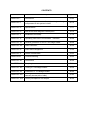
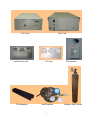
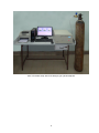
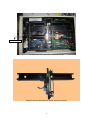
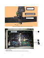
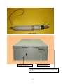
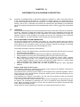
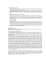
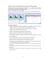
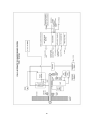
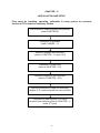
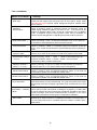
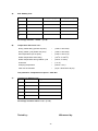
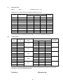
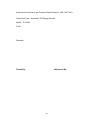
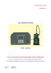
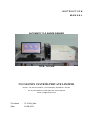
INSTRUCTION
MANUAL
AUTOMATIC TLD BADGE READER
TYPE: TL1010A
NUCLEONIX SYSTEMS PRIVATE LIMITED
Plot No : 162 A & B, PHASE II, I.D.A.Cherlapally, Hyderabad - 500 051
Ph: 91-040-27263701, 2726 1882, FAX: 040-27262146
e-mail : [email protected]
File Name
:
TL1010A_Man
Date
:
20-08-2013
1
CONTENTS
No.
CHAPTER- I
CHAPTER- II
Description
Introduction
Page No.
03-04
Important improvements & major design changes
05-10
incorporated in this system include
CHAPTER- III
Specifications
11-11
CHAPTER- IV
Instrument Block diagram & Description
12-16
CHAPTER- V
Installation and Setup
17-19
CHAPTER- VI
Operating Instructions for hardware / software
20-28
CHAPTER- VII
General guidelines for use of TLD badge reader
29-29
CHAPTER- VIII
Dose evaluation
30-30
CHAPTER- IX
Dose data management
31-32
CHAPTER- X
Reuse of dosimeters
33-33
CHAPTER-XI
Trouble Shooting
34-35
CHAPTER- XII
Precautions
36-36
CHAPTER- XIII
Sample glow curve
37-38
CHAPTER- XIV
Testing of TLD Badge Reader
39-39
CHAPTER- XV
Calibration of TLD Badge Reader
40-40
CHAPTER- XVI
Availing of maintenance/ calibration services and
warranty clause(with in India)
41-45
CHAPTER- XVII
Factory Acceptance Test Report
46-50
2
CHAPTER – I
INTRODUCTION
The Automatic TLD Badge Reader TL1010A is a personnel monitoring system, developed &
manufactured by Nucleonix Systems is primarily designed to read the TLD card (TL dosimeters) worn by
radiation workers. Several Personnel radiation monitoring systems such as photographic films, pocket
ionization chambers and thermoluminescent dosimeters (TLD) have been used for the routine evaluation
of radiation exposures to personnel. Recently there has been a rapid increase in the use of TLD for
personnel monitoring of radiation workers. The TLD systems are preferable over other systems because
of several reasons such as,
a. The availability of a variety of highly sensitive TL phosphors.
b. Wide measurable range.
c. Reusability of the dosimeters.
d. Good post irradiation stability.
e. Rapid read-out capability and
f. Low cost and ease of preparation.
The TLD personnel monitoring system essentially consists of two major parts: TLD badge and the TLD
badge reader.
The TLD Badge comprises of a plastic cassette containing a TLD Card made of aluminum with three
Teflon TLD discs (13.3mm and 0.8mm thick) that are mechanically clipped on to circular holes (12.0mm)
punched on it (52 x 30 x 1mm). Each TLD Card also comprises of a unique punched hole ID which is
readout during the acquisition cycle for identifying the wearer of the TLD
This Automatic TLD Badge Reader is primarily designed to read Bhabha Atomic Research Centre (BARC)
developed CaSo4 (D4) PTFE disc dosimeter based TLD cards. These cards utilize three dosimeters.
The TLD Badge Reader is designed to measure X, Gamma and Beta radiation dose. The metal filter
combination (1mm Al + 0.9mm Cu) is provided to reduce the photon energy dependence of the TL discs.
The TL badge reader is calibrated such that the TL output of the disc under the metallic filter reads directly
the gamma radiation dose.
The TLD Badge Reader system is designed using state of art electronics, stepper motor based electromechanical system, embedded code and software to load and read the TLD cards for TL glow curve / dose
along with personnel ID. The system facilitates entry / printout of Dose records and glow curve for the
o
personnel. TL dosimeter is heated by hot gas (N2) jet to 285 C using a Nichrome heater assembly & TL
output is recorded using PMT whose integral of the current output is proportional to the dose.
In this thermoluminescent dosimeter based personnel-monitoring system, the radiation workers wear the
dosimeter & the radiation exposure is estimated on the basis of TL dosimetric reading.
Thermoluminescent dosimeters make use of the property of certain materials, which absorb energy when
exposed to X, Gamma or Beta radiation. On heating, the absorbed energy is released in the form of
visible light. A plot of light intensity emitted against temperature is known as a glow curve. For a given
heating rate, the temperature at which the maximum light emission occurs, is called the glow-peak
temperature and it is characteristic, of the individual TL material (also called phosphor).
The quantity of the visible light emitted (TL output) is found to be proportional to the energy absorbed by
the TL material. The estimation of radiation exposure may be based either on the height of the glow curve
(differential method) or the area under the glow curve (integral method).
Accessories :
1. Light Source Card
2. TLD Card
3. Cassette
4. Magazine
5. Nitrogen Cylinder
6. Gas Regulator
3
Front View
Light Source card
TLD Magazine
Rear View
TLD card
Gas Regulator
4
TLD cassette
Nitrogen Gas Cylinder
CHAPTER - II
IMPORTANT IMPROVEMENTS & MAJOR DESIGN CHANGES INCORPORATED IN
AUTOMATIC TLD BADGE READER SYSTEM
•
Digital flow rate meter indication is provided for checking flow failure
•
Precision stepping motors are used for (a) Disc positioning (b) Magazine
movement.
•
Digital Linear actuators are used for TLD Card raise and PMT shutter control
•
PC Based design with smart hardware diagnostics using a microcontroller based
design
•
All PCB interconnections across PCBs are through mother board for minimal
wiring and better reliability
•
SMPS power supplies are used to achieve minimum size
•
Highly reliable and precise electro-mechanics, to eliminate any TLD card
positioning errors
•
Front panel LCD display for local indication of fault diagnostic messages
5
Auto TLD reader setup with PC & Nitrogen gas cylinder adjacent
6
PMT housing
Top inside view of the Automatic TLD Badge Reader
Magazine channel assembly with stepper motor drive system
7
.
SMPS power supplies are in this design resulting in no use of bulky power transformers
8
Disc positioning
stepping motor
Shutter control actuator
Magazine movement
stepping motor
High precision stepping motors have been used in this design.
1
4
3
2
1. Temperature Controller PCB
2. Controller PCB
3. Motor Driver PCB
4. Mother board (most of the inter PCB wiring is through mother board)
9
Heater assembly
Magazine loading door
Digital flow rate meter
LCD dot matrix display (16x2) status LCD display
indicates, (card position, Temperature OK, EHT OK, Flow
rate etc.)
10
CHAPTER – III
SPECIFICATIONS
Dosimeter
:
Three-element BARC CaSO4 (Dy) PTFE disc dosimeter badge with
personnel ID.
Light Measurement System
:
Photo-Multiplier tube (EMI 9125B-bialkali) Light measuring system
(LMS).
Dark current
:
Dark current is 1 Sv (CaSO4) equivalent with software-based
sampling & subtraction.
Heater Element
:
Nichrome heater assembly.
Heating Method
:
Hot gas (N2) heating
Nitrogen flow rate measurement :
Digital flow rate meter
Heating Cycle
:
The temperature is raised to 285°C in 8 sec and clamped at 285°C
Dose Range
:
50 Sv-5Sv (Gamma) and 100 Sv-5Sv (Beta)
Dose Threshold
:
<50 Sv
Readout time
:
Approx 100 sec per badge
Residual Signal
:
<10% of reading
Facilities Available
:
Entry of calibration factor, etc. Storage of dose and glow curve data
of badges in Hard Disk. Stepper motor driver assembly for automatic
feeding of 50 dosimeter cards loaded in a magazine.
Software
:
Windows 7 (32 bit) / XP-SP3 compatible software facilitates storage
and display of glow curves, computations of dose & generation of
dose reports, transfer of data to user defined file, etc.
Temperature Monitoring
:
Chromel-Alumel thermocouple in hot gas stream.
Range Selection
:
Automatic
Calibration
:
Coarse adjustment by varying the EHT through a potentiometer in the
EHT circuit.
Safeguards
:
Heater / Gas flow / EHT / Card ID failure: The heater temperature,
gas flow rate, card ID and EHT are checked for failure in every
dosimeter readout cycle. In the event of failure of heater or gas flow
rate or EHT or card ID, the readout is terminated and a message
indicating corresponding failure message is flashed on the PC
monitor.
failure message
:
Any mechanical failure during readout cycle is sensed online & cycle
is terminated with an option for the user to restart the cycle. EHT or
the input circuit (I-F converter) is sensed and reading cycle is
terminated in case of failure.
Nominal Power Supply
:
Power supply: 230V, 50Hz: Power requirements: 500VA (max
including PC)
Minimum PC Requirements
:
Intel Core 2 Duo 2.8 GHz Intel G31, 2GB DDR2, 500 GB SATA,
internet ready optical scroll, 19” TFT monitor, Windows 7 Licensed
OS CD & LaserJet printer (Monochrome).
Applications
:
Personnel monitoring of radiation workers in Nuclear power stations,
Isotope laboratories, Industrial radiography installations, diagnostic &
therapeutic radiology centers, etc.
Mechanical Failure and
11
CHAPTER – IV
INSTRUMENT BLOCK DIAGRAM & DESCRIPTION
4.1.
Automatic TLD Badge Reader is specifically designed to measure TL output of the discs fixed on
to the card along with the personnel ID. It utilizes the integral method of TL measurement as it
involves less stringent requirements on heating rate. The reader basically provides a programmed
heating cycle to the TL dosimeter and senses the instantaneous light emitted by the dosimeter
(glow curve signal) and displays the total integrated light output in terms of Sv (unit of equivalent
dose).
4.2.
CONTROLS
The mechanical assembly & the microcontroller based control circuits are housed in the instrument
enclosure. Apart from a digital flow meter with a control knob for the adjustment of the gas flow
and a 16x2 character LCD display for status information the instrument panel does not have any
operating controls. All the operations are carried out from the PC connected to the instrument
through a USB link. The status indication LCD indicates the instrument ON status.
4.3
BLOCK DIAGRAM & SYSTEM DESCRIPTION
As the block diagram shown indicates, this product is a PC based system where the primary
commands are issued to a micro-controller board through USB port (Virtual communication port is
used). Based on the commands issued, the micro-controller responds accordingly by executing
the required function and sends back acknowledgement code.
The system essentially comprises of the following:
a. Stepper & DLA motor based Electro-mechanical system along with optical sensors for precise
noise-free motion & feedback
b. SS tube based gas heating assembly along with digital flow measurement system.
c. Photomultiplier Tube, along with heat absorbing glass as a light measurement system.
d. Data acquisition & control circuits comprising of micro-controller circuits, heater controller
circuits, high voltage module, I to F convertor module, Stepper / DLA motor drivers module &
LV power supplies. Majority of the circuits are EURO type PCBs sitting on a mother board
PCB. This facilitates easy maintenance in the event of breakdown.
e. Personal Computer (PC) system with TLD data acquisition analysis & report generation
software.
Stepper / DLA motors & driver units:
The magazine positioning is controlled by a stepper motor based on the feedback received from
the 4 optical sensors underneath the magazine.
The optical sensors sense the grooves made on the magazine which generates signature code for
home position & each channel advance. Using this method, precise noise-free positioning at any
of the 50 positions can be done.
Once positioned at a specific card location, the TLD card can be raised by using the card raise
DLA motor for taking readout of the current card.
In the next step, the card is drawn through a optical sensor arrangement so that personnel ID can
be readout. This is followed by positioning at D1, D2 or D3 positions using the belt drive stepper
motor. Before acquisition can begin for a TLD card, the shutter can be opened using shutter DLA
motor. After this acquisition begin.
Using the above motors positioning for readouts TLD card and personnel ID are done.
12
Temperature controller board design requirement :
o
The design principle of the system is that the temperature should rise to 285 C within 10-12
seconds and remain clamped till completion of 30 seconds in disc read mode. So that the
o
temperature of the disc goes upto 285 C.
o
To raise the temperature of the disc to 285 C. The air thermocouple should attain 12mV (44
o
mV/ C Cr-A1,K-type thermocouple) in a leakage free air path. The TL disc emits the glow curve
o
o
peak at 240 C. But for getting maximum glow curve emission the TL Disc is heated upto 285 C.
The temperature controller board is designed to meet the above requirement. It is a dual
proportional temperature controller. The purpose of using two proportional controller is to optimize
the temperature of heater in case of idle state. And to increase the temperature of heater in case
of readout state. Two feed back thermocouples are provide for each proportional controller. To
simply the explanation the one proportional controller having heater thermocouple feedback is
termed as heater temperature controller and the other one having air thermocouple is termed as
air temperature controller and the other one having air thermocouple is termed as air temperature
controller. When the system is in readout state solenoid valve switched ON and the temperature of
the heater is controller by the feedback from air thermocouple. And when the system is in idle
state the temperature of the heater is controlled feedback from the heater thermocouple. The
signals from microcontroller switches the controls in between the two proportional controllers as
well as regulate air flow.
The problem in the temperature section of the TLD system may be due to solenoid malfunctioning,
thermocouple wires and heater element breakdown and leakages in the path and loose
connections leeding to irratic switching of solenoid volve.
In case of breakdown replace the faulty component with new one in heater assembly. In due
course of time TC board may have to be calibrated. If there is a variation observed in the readings.
On receiving the command (HI to LO signal) from the microcontroller, through transistor driver
circuit solid state relay (SSR2) opens solenoid volve to all Nitrogen gas to flow through the flow
system consisting of Digital flow meter & is let into Heater assembly.
Block diagram of Temperature controller section
Nozzle
Heater assembly
Air Temperature
Proportional Controller
Path-1
Logic Switching
ckt, Interface
Control shifting
Interfacing ckt.
HI
Lo
Heater – Temperature
Proportional Controller
Path-1
Solid State
Relay-1
Signal from
Microcontroller
Solid State
Relay-2
Drive circuit
Air flow
Solenoide volve
Air flow
13
1. With readout cycle ON:
Initially the Heater set point at this stage will assume 6000 & through this (path-2) relay (SSR1) goes ON & AC mains power is up rapidly.
With gas flow being on now, gas gets proportional band, resulting into proportional band
making SSR-1 ON/OFF through path-1. Thus temperature controller controls gas temperature
constant during readout cycle for 30sec of disc exposure or 30X3 sec for the card exposure
time.
2. When the Dosimeter readout is not ON:
0
Heater set point will be 190 C. Pulse width modulator control ON/OFF of the SSR-1, to
0
regulate the heater temperature to 190 C. During this time gas flow is cut-off & hence gas
temperature is LOW. Air flow path proportional controller comparator will be outside the
proportional band & path-1 controls signal is OFF. Temperature controller through controls the
heater temperature.
3. Heater Assembly:
Heater assembly consists of a ceramic tube into which Nichrome heater coil is passed. This
heater is pushed into a steel tube. Over this syndania tube is covered for greater insulation. At
hot end of the heater coil there is air thermocouple mounted to measure hot Nitrogen
temperature & in the middle of the heater ceramic tube toward hot end at (2/3) distance from
cold end heater thermocouple is placed. Nichrome heater coil terminals & thermocouple
terminals are all fixed onto a terminals block.
Photomultiplier Tube :
9125B PMT of ETL is used for detection of the light signal. The light signal is converted to
proportional current signal by the PMT.
Data acquisition & control circuits :
The Data acquisition & control circuits are powered by 1 no. of SMPS supplies generating +5V, +/12V respectively. The heater assembly is powered by a separate linear transformer mounted on it.
The other SMPS powers rest of the electronics like digital circuits, analog section, stepper motors,
high voltage etc.
The data acquisition and control unit essentially comprises of a micro-controller board at the heart
which essentially controls all hardware during acquisition or otherwise. Micro-controller receives
commands from PC based on which it responds. It works in slave configuration with PC. Microcontroller board generates signals for precise motion of stepper and DLA motors based on optical
feedback received from corresponding optical sensors during data acquisition. The following
movements are controlled by the micro-controller – Magazine Eject / Home, Magazine move
option, Card raise / lower, card position Home / D2 / D2 / D3, shutter Open / close by the aid of
optical sensors. Once positioning is complete, the acquisition of TL card / light source card / Dark
current is done by the micro-controller. Before acquiring for TL card, the solenoid & heater
o
controller are turned ON to enable gas heating upto 285 C. Once gas temperature is reached, the
TL card is moved to position D1 or as selected and acquisition is carried out. After each disc
readout, card is moved to next disc position & acquisition repeats for that disc. After all readouts
are completed solenoid & heater are turned OFF automatically. All the above motors are driven by
stepper driver modules located on stepper drive card based on signal received from microcontroller. The PMT is biased by a miniature HV module located on the mother board. The PMT
o/p is processed and converted to frequency o/p by a I to F convertor module which is located in
the micro-controller board.
A Ni63 based Light source TLD sized Card is provided separately which can be used for stability
check of the PMT during the acquisition cycle. A light source check command may be issued after
pausing acquisition cycle to check for stability. The Light source TLD card has to be placed in
Magazine Position 1 before carrying out light source check and after acquisition it has to be
removed before proceeding for personnel dosimetry.
14
PERSONNEL COMPUTER SYSTEM WITH SOFTWARE FOR TL BADGE READER :
Personnel computer system loaded with the software for TL Badge reader serves as
comprehensive ‘TL Dose records management software’. It is user-friendly, reliable and feature
rich. It has powerful fault diagnostics reporting capabilities.
Typical PC configuration can be as given below;
Intel Core 2 Duo 2.8 GHz Intel G31, 2GB DDR2, HD, Windows 7 Licensed OS (32 bit) & Printer
Key features of Software:
Provides Commands for complete fault diagnostics of the Reader that includes checking of
Light Source, Dark Current, Heater, Gas flow, EHT, Mechanical movements.
-
Provides screen to enter Institution, Personnel and Card details prior to acquisition.
-
Acquisition of up to 50 cards can be done in one go.
-
Acquisition can be paused & resumed without any loss of data.
-
Fault checks are performed during acquisition and reported to user.
-
Calibration factors for Reader and D1, D2, D3 positions can be set.
-
Dose calculator is provided for calculation of Dose by manually entering Integral TL values for
D1, D2, D3 positions.
-
Glow curve data is stored in Text file and can be optionally exported to Excel.
-
Glow curve data can be viewed at a later data individually for each card.
-
Dose values for each card, Personnel numbers are written to a batch file.
-
Dose information can be optionally written to Nucleonix Dose Records management database
and User wise Cumulative Dose reports can be generated.
-
All TLD cards are enrolled into the database before issue to the user along with dosimeter ID
information.
-
Before acquisition, all cards are scanned for auto identification and reporting of full personnel
information.
-
After acquisition, reports of dose information is tagged to the corresponding user having
corresponding TLD.
15
16
CHAPTER – V
INSTALLATION AND SETUP
Flow chart for installing, operating, calibration & using system for personal
monitor of TLD cards for dosimetry studies.
UNPACKING & Interconnecting sub-systems
(read CHAPTER-V)
Installation of Software
(read CHAPER – V)
Steps for operate the instrument
(refer to CHAPTER – VI upto 6.2.2)
Calibration of instrument
(refer to CHAPTER – XV)
Checking linearity of an instrument
(refer to CHAPTER – XIV)
Now the instrument is ready for dosimetry
studies of TL cards received from any institute
Procedure to read exposed TLD cards
received from institute (refer to CHAPTER – V
under 9th point)
17
i)
Choosing a place for installation: Find a flat, firm surface with enough room to put the TLD
Badge Reader unit along with the Personnel Computer and a Printer. The entire place must be
clean and free from dust and air-conditioned so that the temperature is around 25°C. Do not
operate any noisy equipment near the reader system. Provision should be made for installing a N2
gas cylinder on the right side of the reader. (refer to photographs indicated in this CHAPTER-III, as
you read it)
ii)
Procedure for assembling the reader system: The back panel of the reader unit is provided with
a 9 pin D connector for connecting the reader system to a USB port of a Win XP / Win 7 based
system.
Ensure that the USB drivers are installed by TLBadgeReader.bat file. Connect the communication
cable from TL Badge Reader Electronic Unit to PC USB port. TL Badge reader provides a virtual
USB connectivity to PC. This means that the USB will appear as a COM port on the PC. For
establishing connectivity with the reader, COM port number corresponding to this connectivity
must be identified. To do this, Right click on “My computer” icon on Desktop. Select Properties ->
Device Manager -> Ports. You will find the COM port number. For e.g. If you find “COM3”, it
means that COM port number is 3.
iii)
A gas inlet is also provided on the back panel of the reader unit. Connect a Nitrogen cylinder with
2
the tube provided to the gas inlet of the reader unit. Set the pressure at 2 kg/cm in the pressure
gauge.
iv)
PC installation: The minimum required computer configuration is computer system (Branded)
with Intel Core 2 Duo 2.8 GHz Intel G31, 2GB DDR2, 500 GB SATA, internet ready optical scroll,
19” TFT monitor, Windows 7 Licensed OS CD & LaserJet printer install the PC and printer with the
standard procedure given in PC user's guide. Win XP 64-bit is currently not supported by the
system.
v)
Software installation: To install the software, execute TLBadgeReader.bat in the installation CD.
Follow instructions in Readme file. Click through the options, until you get the message that
installation is completed successfully. In case of any errors, please take a screenshot of the error
message and email to Nucleonix Customer Support.
vi)
Digital Flow meter: At the time of installation, Ensure that the flow control knob provided on the
Digital Flow meter is turned fully clockwise. Turn the knob slowly to anti-clock direction to maintain
the flow rate in the range of 5 – 6 lpm when gas flow is ON.
18
vii)
Power Supply Connections: Connect the reader unit and computer to the power supply (230V,
50Hz). To provide protection to the reader system from spikes in the supply line, take the power
supply connections through a spike buster. It is advisable to use a 500 VA un-interruptible power
supply (UPS) for the Automatic TLD reader system including the PC to ensure data integrity in the
event of a power failure.
Starting the Program: Switch on the computer, Click on Start -> Programs –> Nucleonix Systems
-> TLBadgeReader or Double click TLBadgeReader icon on Desktop to run the application. Then
the software of TLD Badge Reader will be displayed on the PC monitor. The program details are
discussed under SOFTWARE chapter, and the working is discussed under ‘INSTRUCTIONS FOR
HARDWARE/ SOFTWARE’.
viii)
Switching the Reader System: Make sure that the Nitrogen cylinder is connected to the gas inlet
of the reader unit. Now, switch on the reader unit. The reader should be switched on at least 30
minutes before the reading operations to allow for the stabilization of PMT and rest of the
electronics.
ix)
Procedure to read exposed TLD cards :
On receiving the TLD cards from an institution, take out TLD cards from the cassettes, lable
them, arrange them orderly.
As the instrument is already calibrated, start “prepare reader” through software. Refer to
CHAPTER-VI under 6.2.3.There you can check Light leakage, heater and light source.
Load the TLD cards in magazine and enter the card details through software.
Place a control card in magazine first position.
Start acquisition – refer to CHAPTER – VI under 6.2.3. *Start* point.
After completion of acquisition a message window appears as ‘Acquisition completed’. All
data saved in reports as per file name given.
Finally evaluate dose as per your dose evaluation procedure.
19
CHAPTER – VI
OPERATING INSTRUCTIONS FOR HARDWARE/ SOFTWARE
Switch on the computer, Click on Start -> Programs –> Nucleonix Systems -> TLBadgeReader or Double
click TLBadgeReader icon on Desktop to run the application. Then the Login Screen as shown in 6.1
appears on the PC monitor.
6.1
LOGIN SCREEN
Once Application is invoked as described in Chapter V, the application starts and a Window
as show below appears
Enter “admin” as Username, “Nucleonix” as password and click on Login button. This password
can be changed to User’s choice, using the controls on lower part of the screen.
6.2
SOFTWARE OPERATION AND FEATURES
After Login, software performs certain checks before displaying the main screen.
The first check is COM port check. If COM port settings are incorrect, then following windows
appear.
Main screen of the software is displayed after user clicks on Ok button.
Recheck the COM port number and enter the correct COM port number in ”Config-> Set COM
Port‟ menu.
If COM port number is correct, the software then checks for the Reader response. If Reader is
not detected, appropriate message is displayed and Main screen of the software is displayed.
20
Test and Acquire Menu commands cannot be used until correct COM port is set and Reader is
detected.
If reader is detected, the magazine is automatically ejected. This time user has to load the cards in
magazine, insert magazine into the reader and close the door.
Caution: User must not pull or push the magazine while Reader is On. This might cause
mechanical damages.
The main screen of TL Badge Reader appears as below:
6.2.1.
CONFIG MENU
Setting the COM Port
To set COM port, select Config menu and click on “Set COM port‟ . In the window that pops up,
enter the COM port number and click Ok. The application is terminated for the new settings to take
effect. Now Run the application again.
Setting the Card details (Semi-Auto mode of operation)
User needs to provide the card details for the cards to be loaded into the magazine. To do this,
user must click on “Config Menu and “Set Card Details. The below window will appear
21
Various card details like Institution Number, Service Year, Month, Frequency, Personnel ID,
Location code (Chest / Left or Right Wrist / Head), Card type (Worker card/ Control card / Blank
card / Exposed card), Type of Radiation (Gamma / Beta / X-ray) can be entered. „Presence‟
indicates whether card is physically being loaded or not. Clicking on “Insert” button will adds the
card to the list.
This process is to be repeated for each card. User needs to finally click on “Ok”.
Note that these details are stored in memory. In case user exits the application, these details are
lost. This feature is particularly useful for users who receive cards from multiple institutions in
batches.
Setting Calibration Factors
Software provides the facility to set Calibration Factors for D1, D2, D3 data as well as Reader
Calibration Factor for the purpose of normalization of data
By default all the values are set to 1. These factors are multiplied with each acquired data point
and plotted.
22
Setting Control Cards Data
Initial few cards that are loaded into the Magazine are normally Control cards. The data obtained
from these cards will be utilized for Dose calculations. Hence, User must first acquire data from
these Control cards by clicking on “Acquire” Menu and “Start”. Once Control cards data is
obtained, User must click on “Stop” to stop the acquisition and note Control cards data. This must
be entered in the below form by clicking on “Config” Menu and “Set Control Cards data”.
Turning ON/OFF ‘Export data to Excel’ option
Data can be exported to Excel by turning the “Export to Excel‟ option ON. This can be done by
clicking on “Config” Menu, “Data Export to Excel” and “ON”. However, this will add some additional
time to the acquisition cycle.
6.2.2.
TEST MENU
Prior to acquisition, user can conduct various checks on TL Badge Reader hardware. Though they
are not mandatory, the checks can indicate any faults prior to acquisition.
Check Light Source Mode
User has to place Light source TLD card in position 1 in magazine. A constant light output is
generated by a Light source TLD Card. This signal is acquired and plotted. Light source is
physically mounted on D2 position of the TLD Card. Typical data is shown in the figure below:
After completion of Light source test user has to remove the light source card from magazine
before proceeding for dosimetry to prevent accidental damage to the light source by heating
23
Dark Current Mode
In this mode, Light Source is turned OFF, shutter is Open and Heating is OFF. Dark Current data
is acquired and plotted. Typical data is shown in the figure below:
Check Heater
In this check, the Heater is turned ON and the time in which it attains the Set temperature is
recorded. The flow rate should be set > 5 lpm to ensure overheating of Nichrome Heater assembly
is prevented. The duration in which Set temperature is attained is displayed. In case Set
temperature is not attained, then Flow rate and Heater settings have to be verified
Note: At this time user must confirm the flow rate is set or not
24
Test mode for 5 sec: This mode is for checking Heater, magazine move movements and disc
positioning for 50 cards
Dose Calculator
Dose Calculator is provided to manually calculate Dose values by entering Card type (W/C/B/E for
Worker or Control or Blank or Exposed), Type of Radiation (G/B/X for Gamma or Beta or X-ray),
TL Integral values for D1, D2, D3 positions.
6.2.3
ACQUIRE MENU
Prepare Reader for Acquisition
Prior to acquisition, Tests can be individually done using commands in “Test” menu. Alternatively,
user can click on “Acquire” menu and “Prepare reader for acquisition” to conduct various tests in
sequence. The following operations are done in sequence when this command is given: Dark
Current Mode check, Adjust Flow rate, Heater check and
Light Source Mode Check. Followed by Light source check, Magazine will be ejected out for
removal of Light Source TLD Card
When the command ‘Prepare Reader for Acquisition’ is clicked,
25
During Dark current check, EHT check and PMT Dark counts are checked. Incase EHT is faulty
failure messages will be shown
During Flow Rate Check, PC prompts user to adjust flow rate in the range of 5-6 lpm using the
needle valve provided on the digital flow meter. Once it is set, press OK button. This will initiate
Heater check automatically
During Heater Check, the current ADC value corresponding to current temperature is displayed.
Once the current ADC reaches limit ADC value, temperature check is terminated and the time
elapsed for reaching the limit ADC value is shown. This will be corresponding to the final set
Temperature. The final temperature is reached within 20-25 seconds if solenoid / heater / flow
meter are working properly otherwise failure message is prompted
During Light source check mechanical movements are tested partially and PMT gain stability can
be verified. In the event of any mechanical failure light source check is terminated and suitable
message is prompted
Start
Having performed all the Hardware Tests and ensuring the settings are at desirable values, User
is ready to start acquisition. Clicking on “Start” will display the below message:
Will acquire for “n” cards. “n” is the number of Cards entered in Card Details window. User is now
asked to enter the Card number from which to start acquiring the data. User can enter “1”. In case
User is resuming acquisition after “Stopping” to enter Control cards data or for any other reason,
then the appropriate Card number can be entered.
User is then asked to enter the Filename to Save spectrum data.
The acquisition starts and continues for all the Cards. Spectrum Data for each card is viewed by
an option in “File” option tends spectra files ,Dump texts can also viewed by “text file” option in
“File” option. Opened text files can save by “Save” option in “File” option
Note: User must not perform any other operations in this application while acquisition is on. Also,
no other application must be run in the background during this time. Doing this might disturb the
plot.
Stop
This command is useful to Stop acquisition either for Setting Control Card values or any other
reason. The acquisition will stop after acquiring for all 3 Disc positions. To resume after stopping,
User must click on “Start” again and enter the next Card position from which acquisition must
resume.
Eject
This command can be used to Eject the Magazine.
6.2.4
FILE AND REPORT MENUS
Viewing Saved Spectra
Saved Spectra can be viewed in TLBadgeReader application or in Excel. To view in application,
click on “File” Menu and “Open”. Select the filename to open and click ok.
The spectra are retrieved into Memory. To view the spectra, enter the card number in the textbox
next to “Go” button and click on “Go” button. To maneuver, use the “Next” and “Prev” buttons.
Personnel number and Dose details are displayed in the Grid at bottom right.
A sample is shown below:
26
Saved Spectra can also be viewed in Excel. This can be done by clicking on “Report” menu and
“View in Excel”. A typical report is shown below:
This is a comprehensive report with all details related to the card ID. Personnel number, Card
Type, Radn Type, Date, Dose value, D1, D2, D3, Int TLD, Person name and contact details are
displayed.
27
Editing of saved person details:
Editing of Personnel number can also do by this way as shown,
Click on that number below window will appear edit as required and Click OK
Printing of Spectra file:
Printing of spectra file can be done by loading that file and click on the print option top of the
window, window will appear as below and Click Ok to print
6.2.5
HELP
Operating procedures & specific help can be obtained by checking on help menu
6.2.6
ABOUT THIS SOFTWARE
The version number of this software is displayed when “About‟ menu is clicked. Please check with
Nucleonix for the latest upgrades.
Maintenance and Customer Support
Periodic functional checks of system must be performed whenever possible. This can be done by
Customer’s trained employees. Apart from this, PC must be kept free from Virus and backed up by
UPS power.
Customer must enter into Annual Maintenance Contract after Warranty. This will entitle them for
preventive maintenance checks, software upgrades, Re-Calibration, etc.
In case of any queries or issues with the software, you may contact us by email / phone / letter /
fax. Details are given below:
Customer Support Department
Nucleonix Systems P Ltd
Plot 162 A&B, IDA, Phase-2, Cherlapally,
Hyderabad, INDIA. Pin: 5000051
Ph: +91-40-27263701, Fax: +91-40-27262146
Email: [email protected], Web: www.nucleonix.com
28
CHAPTER – VII
GENERAL GUIDELINES FOR USE OF TLD BADGE READER
Temperature & N2 Gas Flow Rate Adjustments: The life & reusability of the dosimeters critically depend
on the maximum temperature to which the dosimeter is subjected to while reading the dosimeter. Hence
the following precautions are to be observed while adjusting these parameters.
Flow Rate: The flow rate should not exceed 6LPM and the inlet pressure of the gas should be adjusted to
2
2 Kg/cm .
Temperature Adjustment: The optimum maximum temperature will be the one that corresponds to a leftout TL (i.e., the TL output from the dosimeter in a subsequent readout) of the order of 10%. Too large a
left-out TL would mean insufficient heating and too less a left-out TL indicates over heating. Over heating,
apart from reducing the life of the dosimeter, results in deformation of the Teflon based dosimeter. The
deformed dosimeter often causes jamming of the card carrier mechanism in the Reader.
The temperature can be adjusted, if necessary, with the potentiometer P3 on the temperature controller
PCB using the 'Heater Check’ from the Test Menu of the TL Badge Reader software. If any adjustment of
temperature is made, the ADC value corresponding to the temperature set point reading on the PC should
be stored as the Temperature Limit Value in Settings Text File. This is necessary as the computer waits for
the heater to stabilize to the ADC value corresponding to the Temperature Limit value
Waiting period for temperature to stabilize: At the initiation of the start command, the system opens the
o
solenoid valve for the gas, starts the heating cycle and waits for the temperature of the gas to reach 285 C
before starting the readout cycle. The waiting period is about 1-2 minutes depending on the ambient
conditions. If it exceeds 2 minutes then heater failure is prompted by the PC and the temperature
controller may need adjustment or could be faulty. Flow rate should not be unduly increased beyond 6
LPM as it is likely to deform the dosimeters.
o
When the temperature reaches 285 C, the readout process starts within 1 or 2 seconds delay. A readout
time per dosimeter is 30 seconds and the 50 cards are read in about 100 minutes. The readings are
stored in the database at the end of readout of each card
Calibration: The reader can be calibrated using a calibration factor which is entered manually at the time
of starting the readout or by varying the EHT which in turn varies the gain of the PMT. However, in the
reader an optimum EHT for the PMT used has been selected (600 – 800V) to obtain the best signal-tonoise ratio in the light collection system. Hence the user is advised to use the calibration factor to calibrate
the reader.
The calibration factor can be obtained using 10 or more cards exposed to a uniform dose of 5 mSv and
reading them in the reader using the above procedure. After the readout is over, 'S' (Statistical analysis)
option in the tool bar can be used to evaluate dose. The software has a provision to exclude readings,
which have a large deviation from the mean. The calibration factor is then the ratio of the actual dose
given to the cards to the mean dose.
29
CHAPTER - VIII
DOSE EVALUATION
Dose evaluation is carried out using some empirical relations which have been arrived at after thorough
experimental work. Usually a minimum reporting value (RV) is decided on the basis of the uncertainties in
the dose evaluation process including those inherent in the basic dosimetry. After calculation of the dose, if
the computed value is less than the RV (default values is 0.2 mSv), dose is reported as zero.
A 16 digit ID code is used for the personnel number. The first 4 digits are assigned for the Institution to
which the person belongs. The last four digits are the personal ID number of the person. The middle four
digits are to indicate the service month (two digits, 1 to 12), frequency of service (one digit, 1 for monthly, 2
for bimonthly & so on) and the nature of radiation environment (one digit, 1 for gamma, 1 for beta / gamma,
2 for X rays / gamma and 4 for diagnostic X-rays) in which the person works. The dose evaluation software
evaluates the dose depending on the code entered as per the following relation:
Keys to abbreviation:
D1
: Reading of dosimeter under Cu-Al filter.
D2
: Reading of dosimeter under plastic window.
D3
: Reading of dosimeter under open window.
RV
: Reporting value. Default value is 0.2 mSv. User selectable.
CR21 : Ratio of D2 reading to D1 reading when exposed to calibration dose. (Default Value 1.1)
CR31 : Ratio of D3 reading to D1 reading when exposed to calibration dose. (Default Value 1.15)
Empirical constants:
A1 = 2.6017, A2 = -15.8861, A3 = 45.5412, A4 = -53.2834, A5 = 22.612.
D1’, D2’, D3’ are D1, D2, D3, minus the control card reading. D1’ D2’ D3’ are equated to zero if less than
zero.
Depending on the nature of the radiation (user selected) one of the following four equations are used.
Gamma :
Gamma dose
Beta – Gamma :
Gamma dose
Beta dose
=
D1’ (equated to zero if less than RV)
=
=
=
D1’ (equated to zero if less than RV)
BMF X (D3’-CR31 X D1’)
zero if less than RV.
Where
BMF (Beta Modification Factor) = 1.397437 + 0.2002848 x K1
Where
K1 = (D3 – CR31 X D1’) / K
Where
K = D2 – CR21 X D1 (If K < 20, then K = 20)
X – Gamma :
If D1’ or D2’ or D3’ <5, then D1’ or D2’ or D3’ = 5
R12 = D1’ / D2’
If R12 > 0.7 then Dose = D1’ (If less than RV equate to zero)
2
3
4
Else Dose = D1’ X (A1 + R12 X A2 + R12 X A3 + R12 X A4 + R12 X A5 )
(Equate to zero if less than RV)
Diagnostic X- Rays:
If D1’ / D2’ < 5 then dose is evaluated as above.
If D1’ / D2 > 5 then
Dose = (D2’ + D3’) / 20 with the following message
Badge worn over lead apron
or lead apron not used.
30
CHAPTER - IX
DOSE DATA MANAGEMENT
When the dose evaluation software is executed four files are generated or appended (if already existing).
Two files ‘RED.DAT’ & ‘RD.DAT’ in the format given below are created as a fresh, every time the dose
evaluation software is executed. Both these files are used as a temporary input files during the dose
evaluation routine.
File format of temporary files rd.dat & red.dat.
9906100620010001
9906100620010011
9906100620010021
9906100620010031
00007547
00007407
00007443
00006678
00064086
00063076
00074086
00068089
00053152
00063151
00059959
00063758
The third file generated is the “PERS.DAT” file which contains the entire dose readout details such as the
16-digit personnel number, the three dosimeter readings and the evaluated dose. A typical PERS.DAT file
format is shown below.
--------------------------------------------------------------------------------------------------------------------------Inst
No.
Pers
No.
Serv
Mon.
Serv
Yr
Serv
Freq
Loc
code
Disc-1
Disc-2
Disc-3
Gamma
mSv
Beta
mSv
--------------------------------------------------------------------------------------------------------------------------------- -----000011
000011
000011
000011
000011
000011
000011
1200
1201
1201
1202
1203
1204
1205
01
01
01
01
01
01
01
99
99
99
99
99
99
99
1
1
1
1
1
1
1
0
1
1
2
3
3
0
00007547
00007895
00000658
00000548
00000464
00000385
00000386
00064086
00077920
00000621
00000520
00000464
00000376
00000456
00053152
0007986
00000593
00000507
00000441
00000357
00000645
7.5
7.9
0.6
0.5
0.5
0.4
0.4
0.0
--------------------------------------------------------------------------------------------------------------------------The fourth file generated is the “DOSE.DAT” file that contains just the personnel number and the evaluated
dose. The following is a typical DOSE.DAT file. This file gets appended every time the dose evaluation is
done for a set of cards. This file is called in the ‘Print dose report’ option. The format of the ‘dose.dat’ file is
shown below.
-------------------------------------------------------------0000110110120096
7.5
0000110111120196
7.9
0000110111120196
0.6
0000110112120296
0.5
0.0
0000110113120396
0.5
0000110113120496
0.4
-------------------------------------------------------------THE DOSE REPORT FILE “DOSE.REP” :
This file is created (appended if already exists) when the “Print Dose Report” option is invoked from the
print menu. During this operation, three files ‘DOSE.DAT’ (generated in the dose evaluation menu).
“INSTIT.FLE & PERSN.FLE” (generated using the “Create File” utility) are used. The Institution name,
address and the personnel name are obtained using the appropriate codes in the 16-digit personnel
identification code. The dose stored against this personnel identification code in the ‘dose.dat’ file is
printed and also stored in the “DOSE.REF” file. During the process a temporary file ‘IPSN’ is created in the
current working directory. A typical dose report print-out is shown below.
31
Dose report
INST. CODE
ADDRESS
:
:
0011
Bhabha Atomic Research Centre
RPIS, RPhD
Mood Labs, Trombay
Bombay, PIN : 400 085
------------------------------------------------------------------------------------------- --------------------------------------Pers.
Name
Month
Radia.
Dose (mSv)
Skin
Remarks
No.
/ Year
Field
Whole Body
---------------------------------------------------------------------------------------------------------------------------------1200
Mr. S.J. Gandhi
01/96
Gamma
7.5
0.0
1201
Ms. P.T. Jain
01/96
X-Gma
7.9
1201
Ms. P.K jadhav
01/96
X-Gma
0.6
1202
Mr. C.M. Katoch
01/96
Bt-Gm
0.5
1203
Mr. D. Suresh
01/96
Dia-X
0.5
1204
Mr. M.R. Patil
01/96
Dia_x
0.4
1205
Mr. K.R. Nair
01/96
Gamma
0.4
--------------------------------------------------------------------------------------------------------------------------------A file named “DREP.MSG” stored as a text file in the current working directory is accessed at the end of
“Print Dose Report” routine. This file is to be created by the user in the dos edit mode. The contents of this
file will be printed at the end of the dose report. In this file the user can store any message, note, user
identity etc. which he would like to be printed at the end of the dose report.
These files can be used with appropriate software packages for updating & maintaining the dose records
of the personnel.
32
CHAPTER - X
REUSE OF DOSIMETERS
There is a 10% left over TL after the 30 sec readout in the reader. The cards, therefore, are required to be
annealed before reuse as per the following procedure.
TLD cards are first cleaned in acetone to remove grease, dust particles, if any, sticking to the dosimeter
discs. This done by keeping the cards immersed in acetone container for about an hour. Thereafter,
acetone is removed by pouring out into another container. The cards are kept overnight in the container
so as to completely remove traces of acetone. These cleaned cards are transferred to a stainless steel
tray and introduced into a programmable temperature oven with air circulation. The oven is then switched
o
on and the temperature of the oven is raised to 230°C +/-2 C in about 60 minutes. The temperature is
maintained at 230°C for 3 hours and then the oven is allowed to cool to less than 50°C. The cards are
then taken out and are ready for reuse.
33
CHAPTER - XI
TROUBLE SHOOTING
In case of any failure in instrument during acquisition, that failure will reflect in LCD display of Instrument
as below Failure Code format and a failure message will appear in software
FAILURE CODE ON LCD DISPLAY
CRF
SOFTWARE MESSAGE
Card rise Failure
CLF
Card lower Failure
CPHF
Card Home Failure
MHF
Magazine Home Failure
S0F
Shutter Open Failure
SCF
Shutter Close Failure
MPF (n=1 to 50)
Magazine position n Failure (n=1to 50)
CP1F
Card position 1 Failure
CP2F
Card position 2 Failure
CP3F
Card position 3 Failure
TEMPF
Temperature controller Failure
FLOF
Flow Failure
EHTF
EHT Failure
:T1#F!
Temperature / Gas flow failure
F CODE
Code Error
N CODE
No card
34
FAULT DIAGNOSIS
Nature of Problem
Remedy
Door open
Close the door tightly until LED goes OFF on front panel. Check using
Command Prompt by entering “:MD#”. Response should be “:MD#0!” when
door is Closed
Magazine
home Failure
Check by entering “:MH#” in command prompt ,its response should be
“:MHO”;Check whether magazine is moving or not , if not there may be
problem in Magazine drive motor. Check all connections to the magazine
motor. If magazine stops at wrong position ;there may be mismatch of
position sensor arrangement, by adjusting that problem will be resolved
Card lower Failure
Check by Entering “:cDL#” ; its response should be “CLO” ,if not ,check all
connections of Card raise/lower sensor PCB and Z-motor .
Card raise Failure
Check by entering “:cDR#” in command prompt, its response should be
“CRO” ,if not ,check all connections of Card raise/lower sensor PCB and Zmotor .
Check by entering “:cSH#” in command prompt , its response should be
“CPHO”;if not check all connections of Card home position sensor PCB
Card Home
Position Failure
Card Position n failure
n=1 to 3
Check by entering “:cS1#” / “cS2#” / “cS3#” in command prompt. Its
response should be “CP1O” / “CP2O” / “CP3O” ”;if not check all
connections of Disc position sensor PCB
Magazine position n
Failure ;n = 1 to 50
Check by entering “:mnn#”(n=1 to 50)in command prompt ,its response
should be “MPnnO”; if not check position sensor arrangement
Shutter Open Failure
Check by entering “:s0#”. Its response should be “SOO”. If not check all
connections of shutter control PCB and Shutter motor
Shutter Close Failure
Check by entering “:s1#”. Its response should be “SCO”. If not check all
connections of shutter control PCB and Shutter motor
Flow rate Failure
Read Flow Rate by turning Solenoid ON. If it is not set properly then adjust
and recheck Flow rate on display. Otherwise check connections Flow+ and
Flow –
Temperature
Failure
EHT Failure
controller
Check this by Heater check option in software or by entering “:T1#”and wait
for 30 sec. Ensure flow rate is showing 6 LPM during acquisition. Now issue
a fresh command “:T1#” and its response should “:T1#1400!”. If not, check
Temperature Controller board as given in temperature calibration.
Measure EHT at MHV socket on Temperature controller / HV PCB cable. If
it is not coming then there is a problem with EHT module. It needs repair /
replacement
35
CHAPTER - XII
PRECAUTIONS
1. The light-tight compartment should be closed when the unit is in ON condition. If the upper cover is to
be open in ON condition, remove the HV connector from PMT before switching the unit ON.
2. Removal of PMT from PMT housing should be done in a dark room only. (PMT is sensitive to light).
3. While readouts are in progress if Hardware Failure occurs due to mechanical failure then follow the
below procedure.
a. If the failure is mechanical in Nature, then switch OFF the TLD unit to prevent mechanical
damage to channel / magazine. Next try to restore the jammed TLD Card first into its
magazine slot and powering unit back ON. Card will automatically get lowered back into its
slot in the magazine.
b. Remove any / all deformed TLD Cards to prevent the magazine from getting stuck
c.
Reload the magazine and close the Reader dark chamber cover and Top hinged cover.
d. Switch ON the system and read the remaining cards.
4. The channel should be regularly cleaned with cotton to remove dust & foreign particles.
5. In case of communication error message, ensure correct COM port assignment in software & check for
cable connectivity.
6. Check for the Door LED ON/OFF. When door is closed only RED LED has to glow. Door Open Error
should get reported in software during Acquisition if door is opened
Important Note:
Ensure the light tight compartment & upper cover is in closed condition before switching it ON.
36
CHAPTER - XIII
SAMPLE GLOW CURVE
DUMP TEXT FILE
This can view directly from software “file “option tends “Open text file”
37
READOUT SHEET
Calibration Factor : 1.00
0003100000000010
0003100000000020
0003100000000030
0003100000000040
0003100000000050
0003100000000060
0003100000000070
0003100000000080
0003100000000090
0003100000000100
0003100000000110
0003100000000120
0003100000000130
0003100000000140
0003100000000150
0003100000000160
0003100000000170
0003100000000180
0003100000000190
0003100000000200
0003100000000210
0003100000000220
0003100000000230
0003100000000240
0003100000000250
0003100000000260
0003100000000270
0003100000000280
0003100000000290
0003100000000300
0003100000000310
0003100000000320
0003100000000330
0003100000000340
0003100000000350
0003100000000360
0003100000000370
0003100000000380
0003100000000390
0003100000000400
0003100000000410
0003100000000420
0003100000000430
0003100000000440
0003100000000450
0003100000000460
0003100000000470
0003100000000480
0003100000000490
0003100000000500
D3
D3
D3
D3
D3
D3
D3
D3
D3
D3
D3
D3
D3
D3
D3
D3
D3
D3
D3
D3
D3
D3
D3
D3
D3
D3
D3
D3
D3
D3
D3
D3
D3
D3
D3
D3
D3
D3
D3
D3
D3
D3
D3
D3
D3
D3
D3
D3
D3
D3
00000031
00000034
00000033
00000031
00000031
00000031
00000025
00000030
00000037
00000040
00000040
00000046
00000047
00000045
00000045
00000049
00000052
00000047
00000045
00000053
00000047
00000046
00000043
00000047
00000051
00000046
00000067
00000060
00000048
00000053
00000047
00000047
00000054
00000047
00000049
00000050
00000047
00000053
00000052
00000052
00000062
00000054
00000052
00000058
00000061
00000058
00000059
00000061
00000068
00000088
D2
D2
D2
D2
D2
D2
D2
D2
D2
D2
D2
D2
D2
D2
D2
D2
D2
D2
D2
D2
D2
D2
D2
D2
D2
D2
D2
D2
D2
D2
D2
D2
D2
D2
D2
D2
D2
D2
D2
D2
D2
D2
D2
D2
D2
D2
D2
D2
D2
D2
38
00000057
00000097
00000052
00000094
00000082
00000045
00000065
00000056
00000074
00000081
00000084
00000085
00000076
00000079
00000095
00000117
00000102
00000078
00000092
00000104
00000081
00000082
00000091
00000081
00000088
00000074
00000106
00000082
00000077
00000090
00000088
00000088
00000076
00000090
00000092
00000081
00000096
00000085
00000086
00000099
00000102
00000108
00000082
00000087
00000088
00000076
00000136
00000102
00000088
00000118
D1
D1
D1
D1
D1
D1
D1
D1
D1
D1
D1
D1
D1
D1
D1
D1
D1
D1
D1
D1
D1
D1
D1
D1
D1
D1
D1
D1
D1
D1
D1
D1
D1
D1
D1
D1
D1
D1
D1
D1
D1
D1
D1
D1
D1
D1
D1
D1
D1
D1
00000077
00000065
00000088
00000078
00000072
00000056
00000072
00000051
00000081
00000084
00000082
00000099
00000083
00000089
00000090
00000105
00000088
00000083
00000094
00000238
00000078
00000081
00000105
00000088
00000083
00000072
00000093
00000094
00000100
00000082
00000091
00000097
00000089
00000079
00000095
00000083
00000087
00000099
00000113
00000094
00000088
00000101
00000096
00000100
00000087
00000093
00000113
00000095
00000085
00000110
CHAPTER - XIV
TESTING OF TLD BADGE READER
1. Light Leakage
:
Check the readout of freshly annealed card in bright room as well as
in the dark room.
2. EHT to PM Tube
:
After warm up time of 30 minutes, EHT should not vary by more than
+1v throughout the read out process.
3. Light Source Reading
:
The repeated LS reading can be taken in the reader test mode. The
light source reading should not vary by more than + 5% throughout
the day.
4. Read out temperature
:
The clamping temperature as per the display should be around
o
o
285 C. +2 C and should reach within 50-60s from the start of heating
cycle. The flow rate of N2 gas should be set in between 5-6 lpm.
Changes in the flow rate may cause significant variation in the
readout.
5. Glow Curve and Uniformity in Readout: Expose 10 (Selected) TLD cards sandwiched between
perspex build-up plates (thickness 4-5 mm) to about 4-5mSv of Cs137 gamma rays. TL readouts of all the cards should be taken and
uniformity of gas heating can be checked by recording glow curves
and comparing their stability.
6. Residual TL check
:
Second readout of the above cards should be taken to check the
residual TL. The second readout should not be more than 10-12% of
the first readout. If it is more either flow rate or air temperature point
has to be adjusted.
7. Reproducibility of the TL Readout: For this test, atleast 10 selected TLD cards should be used. The
cards are to be annealed, exposed in build-up plates and read after
one day after the exposure. Cycle to cycle variation of average TL
readout should be within +10% and incase of any significant change,
the response should have an established trend. Minimum three
cycles of annealing, exposure and readout has to be carried out.
8. Minimum Measurable Dose :
The readout of some freshly annealed TLD cards (atleast 10 cards)
should be taken. The minimum measurable dose can be obtained
from the value of 2 .
9. Linearity test
Expose freshly annealed cards (a minimum of 5 doses, 5 cards for
each dose) in the dose range from 0.3mSv to 1Sv of Cs-137 gamma
rays and readout of all cards should be taken in similar conditions.
The TL response (average TL/mSv) should be within + 10% in the
entire dose range covered.
:
39
CHAPTER - XV
CALIBRATION OF TLD BADGE READER
1.
Setting of TLD Reader: The TLD readers should be kept “ON” for atleast half an Hour for warm-up
before starting the actual measurements on it.
After LS measurements, readout of 2-3 dummy
TLD cards should be taken to check the temperature and heating profile. Then take readout of
three exposed calibration cards to confirm the calibration of the reader and if required either
Reader Calibration Factor (RCF) should be changed or EHT to the PM tube should be adjusted to
indicate the counts in desired proportion to dose (1µSv – 1count).
2.
Intermittent check of TLD Reader Sensitivity: The reading of
63
Ni light source TLD Card &
Calibration Cards can be taken intermittently in a day.
NOTE
CAUTION : Do not open light compartments in unit “ON” condition.
Incase of any Hardware failure while taking readouts, follow the below procedure
1.
If the failure is mechanical in Nature, try to restore the jammed TLD Card first in its magazine slot
by powering the unit OFF and powering it back ON. If the deformation on the Card is removed
then the card will automatically go back into its slot.
2.
Remove any / all deformed TLD Cards to prevent the magazine from getting stuck
3.
Reload the magazine and close the Reader dark chamber cover and Top hinged cover.
4.
Switch ON the system and read the remaining cards.
40
CHAPTER – XVI
AVAILING OF MAINTENANCE/ CALIBRATION SERVICES AND WARRANTY
CLAUSE (with in India)
16.1
GENERAL
As per the warranty clause of the company, we provide one year warranty during which period we
provide free service at our works. Hence in case of any mal-function in our instruments, you are
requested to send the unit back to our works by RPP/COURIER/SPEED POST
PARCEL/GATI/XPS/door delivery. We shall arrange immediate rectification/replacement within
two weeks from the date of receipt of the equipment at our place. Please note that the equipment
will be serviced at our works only.
The equipment is to be sent to:
The Servicing Department
NUCLEONIX SYSTEMS PRIVATE LIMITED
Plot No: 162 A & B, PHASE II, I.D.A. Cherlapally,
Hyderabad - 500 051Ph: 040-27263701/329145448/32918055
E-mail: [email protected] www.nucleonix.com
For all the Radiation monitoring equipment, detectors built-in or external probes will not have oneyear warranty, but only inspection warranty at the time of supply is provided. Since detectors will /
may have fragile glass construction, we do not provide warranty. In case of failure of these
components, Nucleonix will supply detector replacement at cost-cost price.
Note: In respect of all types of portable radiation monitors, it may be necessary to checkup and
recalibrate the equipment once a year at our works.
16.2
EQUIPMENT REPAIRS / SERVICING POLICY (WITH IN INDIA)
(a)
During Warrantee
The following procedure is to be followed by the customers with in India for availing services/
repairing facility during warrantee period.
Equipments are to be sent to our works for availing free repair services during warrantee, after
the customer receives approval from the customer support division, by sending an e-mail.
For all equipments, costing less than 6.0 lakhs one year warrantee & free service is offered,
when the equipments are sent to our works only. For larger systems such as installed
systems, networked systems, specialized systems, costing more than 6.0 lakhs during one
year warrantee, free service is offered at site. Field service Engineer will be deputed subject to
warrantee terms & conditions.
This does not include personal computer related problems, for which local computer service
provider of the PC vendor is to be contacted. Also for software related problems online support
will be provided. Software support doesn't include cleaning of virus problems etc.
When the equipments are sent to our works for warrantee services, they are to be properly
packed with adequate cushion to prevent any transportation damages. Nucleonix Systems is
not responsible for damages or loss during transportation.
Packing / Freight charge is to be borne by customer when he sends the equipment to our
works. However when we return after servicing packing will be Nucleonix responsibility &
Freight charges will be to your account. Only services are free.
Please indicate in your correspondence equipment model & serial number.
All the equipments are to be sent to our works only on door delivery basis.
For Door Delivery Transportation contact XPS/GATI cargo in your city / town or a reliable
courier service to pick the consignment from your place. For their nearest local address &
phone no's look into their websites. Transit insurance if the customer feels is necessary it is to
be covered.
41
Nucleonix Systems will not receive the equipments sent by other modes of transportation,
such as Rail/Road.
After servicing, equipments will be sent back by same mode of transport such as
XPS/GATI/COURIER/RPP.
All types of Radiation detectors, glass ware, PMTs etc which are fragile are not covered in
warrantee, if the failure is due to physical damage, external or internal due to shock, dropping,
miss-handling etc. If the failure is due to a natural fault then only it is covered under warrantee
for a limited period of three months. However complete electronics is covered for 1 year
warrantee.
You can also send the equipment personally to our works for repairs either during or after
warrantee, after fixing up with our service dept (Customer Support Division). If possible we
may repair on same day or your person can stay for a day or two & get it repaired & or
calibrated.
(b)
After warrantee Services
On expiry of 1yr warrantee if you like to send the equipment (low cost less than 6.0 lakhs) for
repairs to our works, you may please observe the following procedure.
Send an e-mail with details mentioning that you agree to pay service charges which includes:
Basic service charges per unit / module in the range of Rs: 2500 to Rs : 10,000 depending on
the sophistication of the unit calibration charges ( if applicable for your equipment) + cost of
components + packing charges + Return Freight charges @ actual.
Once our customer support department responds & requests you to despatch the equipment
to our works for repairs, you may do so by following the steps given below.
Followed by this you can send the equipment straight away if it is within 5 yrs old. If the
equipment is beyond 5 yrs old, then also you can send it for repairs, however only after you
receive confirmation from Customer Support Division, that it is repairable & is not an obsolete
model. If the design is obsolete then customer support division (CSD) may give you 'buy back'
offer to replace with new model or upgrade it with electronic circuit boards & enclosure.
For all installed equipments costing above Rs: 6.0 lakhs which are larger in size & for which
field servicing only is recommended, you can obtain a quotation with relevant details by
sending an e-mail & avail the services accordingly.
For all field servicing jobs, since we need to depute engineers, it is likely, to take time & also it
will cost more which includes Engineer's TA & DA etc., apart from basic service charges + cost
of spares etc. Please note that basic service charges will be different for different products
depending upon sophistication.
Also in some cases it may not be possible to fix-up the problems in the field itself, in such
cases we may advise you to send them to our works.
For all jobs to be serviced in the field, customer is requested to provide adequate details on
the nature of problems, to enable our engineer to come prepared with adequate spares.
For any additional information send an e-mail to [email protected], Atten: Customer support
division.
16.3
EQUIPMENT REPAIRS / SERVICING POLICY (FOR EXPORTS)
Equipments, manufactured & exported are subjected to a well defined quality assurance (QA) plan
& Factory acceptance tests (FAT). Nucleonix systems has the following policy to provide
maintenance support to overseas customers either directly or through international dealers /
distributors.
(a)
During & after warranty:
For minor problems, which can be handled by customers, servicing tips have been provided in
the user manual / servicing manual.
Also most of the equipments have built-in fault diagnostic features which will indicate to the
user nature of problem in the equipment. Based on the visual indication in the instrument
Display, user can take corrective action or contact Nucleonix systems by email for help.
Nucleonix systems will guide in localizing the defective part / module or sub-system by
interacting with the customer if required. Skype will be used for communication.
42
During warranty free replacement of sub-system or board (PCB) will be done. However
customer has to send defective sub-system back to Nucleonix system with-in 15 days on
arranging replacement.
During & after warranty, any Freight charges & customs clearance charges are to be borne by
customers, both ways.
If it is a manufacturing defect, then Nucleonix system will bear the replacement cost of subsystem / unit. However any Freight charges & customs clearance charges in their country are
to be borne by customer.
After warranty, services will be similar to that of services during warranty. However, customer
will have to pay for cost of parts replaced, freight charges both ways & customs clearance
charges in both the countries. Nucleonix systems plans to introduce audio visuals on web or
on CDs to facilitate product demonstration, installation & minor maintenance very soon.
16.4
HOW TO AVAIL CALIBRATION SERVICES (FOR INDIAN CUSTOMERS)
Nucleonix Systems offers radiation calibration services to its customers. Calibration services are
provided for Nucleonix Systems manufactured products only, in general, as a company policy.
How to avail calibration services:
It is best advised that each of the Radiation monitors including Area monitors are calibrated once
in a year. When you want to send your Radiation monitor / Area monitor / Contamination monitor
for calibration to our works. You may send the equipment for calibration, by following the steps
given below:
1. Our standard calibration charges per equipment (All types of Radiation monitors including
portable survey meters, contamination monitors & Area Gamma Monitors) are Rs: 2500 +
Packing + Freight charges. You can email a ‘work order’ accepting these charges.
2. Email your work order and despatch / send the equipment to our works if it is 5 years old or
less including details of mode of transport sent with docket particulars.
3. Also mention in your work order & clearly indicate that you will agree to pay calibration
charges & also equipment repair charges additionally if the unit is faulty & requires repairs
before one can take it up for calibration.
4. You are requested to ensure good packing to avoid any transportation damages. Especially if
there are external detector probes, they are to be packed with sufficient soft foam to ensure no
damage in transportation.
5. Use only the specified following mode of transportation system for dispatching on door
delivery basis. XPS/GATI cargo / Courier/RPP/Speed Post parcel etc. Send the equipment on
freight paid basis. (Equipments sent by other methods such as Rail/Road etc will not be
collected). Also you can cover for transit insurance both ways if you wish. Nucleonix system is
not responsible for any transportation damages or loss during transportation both ways.
6. Immediately on receipt of the equipment, we will send an acknowledgement & also a proforma
bill by email/ post.
7. Based on the proforma bill, once we receive the payment, equipment will be dispatched back
by similar mode of transportation as mentioned above.
16.5
HOW TO AVAIL CALIBRATION SERVICES (FOR FOREIGN CUSTOMERS)
Foreign customers can calibrate Nucleonix make Radiation monitors/equipments in their country at
any of their accredited Radiation calibration labs. Nucleonix systems will be happy to provide any
help and guidance if needed, for calibration. Alternatively if you send the equipment here to India
we can also provide calibration services.
Calibration Standards Lab & Facility:
We have two calibration labs.
i.
ii.
Low Level Calibration Lab.
High Dose Rate Calibration lab.
43
Low Level Calibration Lab: This has a Cs-137, 165 mci standard. "Gamma Survey Instruments
Calibrator" from Amersham.
This calibration service has NIST Traceability standard. Calibration of all portable radiation
monitors, survey meters, contamination monitors, Area monitors etc., is carried out in this lab upto
1 R/hr max dose rates.
Gamma Survey instruments calibrator has Cs-137 source 161.5 mCi as on 05 Aug 2002. It is
basically a gamma survey instruments calibrator procured from AEA Technologies UK/USA. Has
NIST traceability accuracy within +/_ 7%
High Dose Rate Calibration Lab: This lab has a 8 Ci, Co-60 standard housed in a CRC-2
camera, operated remotely viewed through CCTV arrangement. High dose rate survey meters,
High level Area monitors etc are calibrated in this lab. This CRC-2 camera is housed in a separate
concrete building. All the radiation monitors manufactured by Nucleonix Systems are authentically
calibrated at this facility, before they are shipped / dispatched.
CRC-2 camera has Co-60 standard obtained from Bhabha Atomic Research Centre, Mumbai. It is
a certified source.
16.5
ANNUAL MAINTENANCE CONTRACT (AMC)
Annual maintenance contract (AMC) services:
For all sophisticated instruments & systems and also for installed monitors & networked systems in
a nuclear facility or a Radiological lab or in a Medical cyclotron facility where no. of instruments are
networked, it is advised that customer enters into an economical Annual maintenance contract
with Nucleonix system.
Detailed AMC proposal can be obtained from our customer support division (CSD), by giving
required inputs.
Inputs required by our CSD to send you AMC proposal:
Name, year & data of purchase, Sl. Nos. of equipments, Model No's, No. of equipments for
which AMC is required. Additionally no. of calls per annum required for preventive &
breakdown maintenance may also be indicated.
44
Advantage of entering into AMC:
Equipment services offered will be prompt & timely
Nucleonix systems maintain required spares, spare tested PCBs, detectors & other critical
components which may become obsolete.
Obsolescence in electrons is quite rapid. If you enter into AMC guaranteed service for the
period of AMC will be the responsibility of Nucleonix Systems.
Nucleonix Systems will maintain Engineers at your disposal to attend to AMC calls on time
Without AMC prompt service calls are not guaranteed.
If some critical components become obsolete, then Nucleonix systems may request you to
upgrade the product with new model or new electronics which may be expensive if you are not
under AMC.
Training on maintenance / servicing:
To a limited extent, we offer training on maintenance / repairs at our works to customers on
chargeable basis. Details can be obtained from our customer support division, by customers
who may require such services.
45
CHAPTER – XVII
FACTORY ACCEPTANCE TEST
REPORT
FOR
AUTOMATIC TLD BADGE READER
MODEL NO. : TL1010A
W/O:
DATE:
SL NO:
Customer Name & Address:
.…………………………………………………………………………..
……………………………………………………………………………
NUCLEONIX SYSTEMS PRIVATE LIMITED
Plot No: 162 A & B, Phase II, I.D.A. Cherlapally, Hyderabad - 500 051.
Ph : 91-040-27263701, Fax : 27262146, e-mail : [email protected]
46
A)
EHT Stability Test :
S.No
Date
EHT (V) (Display)
EHT (V) (Actual)
1.
2.
3.
4.
5.
Percentage Variation < 0.05% : (Y / N)
B)
Temperature Set Points Test :
During reader idiling (Heater set point)
:
(150mV <S.P<250)
During reader cycle (Heater set point)
:
(150mV <S.P<600)
Gas temperature (Air set point)
:
(270mV <S.P<315)
Heater temperature while idiling
:
(150 C <T<200 C)
Heater temperature during readout cycle
:
(400 C <T<50 C)
Overshoot
:
(< 2º C)
Clamping temperature
:
(290ºC +/-5ºC)
Flow rate as indicated
:
(4Lpm <Flow Rate <6Lpm)
o
o
o
o
Test passed for Temperature set points : YES / NO
C)
Light Source Stability Test :
S.No
Date
Light source
1
2
3
4
5
Percentage variation within +/- 5% : (Y / N)
Tested by :
Witnessed by :
47
D)
Mechanical movements :
1.
Reliability test of mechanical movements (50 cycles with zero failures)
2.
a. Shutter motor control
:
OK / Fail
b. Card raise / lower motor control
:
OK / Fail
c. Magazine positioning test for 50 positions
:
OK / Fail
d. Card transport motor control (Home, D1, D2 and D3)
:
OK / Fail
Solenoid operation test
Test passed for Mechanical movements : YES / NO
E)
Annealed Card Readings :
EHT:
Calibration factor: 1.00
Readings of ten freshly annealed cards
S.No
Card code ID
Readings
D1
D2
1
2
3
4
5
6
7
8
9
10
Average
Mean annealed card reading (<100 Sv) :
Stdev
:
% Stdev :
Tested by :
Witnessed by :
48
D3
F)
Dosimetry Test
Adjust
EHT =
Calibration factor = 1.00
Readings of TLD cards uniformly exposed to 300mR to (Cs-137)
S.No
Readings
Card code ID
D1
D2
D3
Average
1
2
3
4
5
6
7
8
9
10
The average observed readings should be within +/-10% of the expected readings
G)
Linearity Test
S.No
Card code
ID
Exposed dose
(mR)
Readings
Average
1
2
100
3
4
5
200
6
7
8
300
9
10
11
400
12
13
14
500
15
The average observed readings for the various doses of exposure in the range of 100 to 500mR
are within +/- 10% of the expected readings
Tested by :
Witnessed by :
49
Instrument functional as per Technical Specifications : (OK / NOT OK)
Instrument Type : Automatic TLD Badge Reader
Model : TL1010A
S.No. :
Remarks
Tested By :
Witnessed By :
50