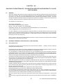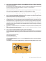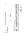
1
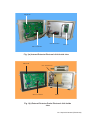
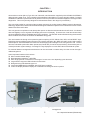
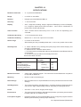
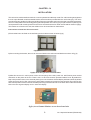
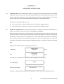
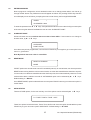
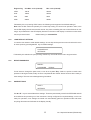
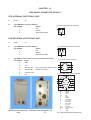
INSTRUCTION
MANUAL
GAMMA AREA MONITOR
INTERNAL DETECTOR
EXTERNAL DETECTOR PROBE
NUCLEONIX SYSTEMS PRIVATE LIMITED
Plot No : 162 A & B, PHASE II, I.D.A.Cherlapally, Hyderabad - 500 051
Ph: +91-040-27263701/30918055, FAX : 040-27262146, e-mail : [email protected]
File Name
:
GA720 / GA720H_Man
1
Ver. Hospital & General (PRM board)
Contents
S.No.
Description
Unpacking
CHAPTER I
Introduction
CHAPTER II
Front panel and Side panel controls /
indications / diagrams
CHAPTER III
Specifications
CHAPTER IV
Installation
CHAPTER V
Operating Instructions
CHAPTER VI
Side panel Connector Details
CHAPTER VI I
Calibration
CHAPTER VIII
Availing of maintenance / calibration services and
warranty clause
CHAPTER IX
Block diagram & Description
CHAPTER X
Factory acceptance Test /
QA Report / Calibration Data
2
Ver. Hospital & General (PRM board)
UNPACKING
The Gamma Area Monitor Type: GA720 / GA720H has been thoroughly tested and is dispatched in ready to
operate condition. However, on unpacking and prior to operation, it is advisable to check visually and make sure
that there is no visible damage caused in transit.
If any damage to the instrument is observed, do not switch ON the unit and report the matter immediately to:
Customer Support Division
Nucleonix Systems Private Limited
Plot No: 162 A & B, PHASE II,
I.D.A.Cherlapally,
Hyderabad - 500 051.
Ph : 91-040-27263701/30918055, FAX : 91-040-27262146, e-mail : [email protected]
In all correspondence regarding the instrument, please mention the type, serial number of the unit, date of supply
etc., of the unit.
3
Ver. Hospital & General (PRM board)
Main PCB
ON/OFF Switch
Detector
Micro Controller
Fig. 1(a) Internal Detector Electronic Unit Inside view
Main PCB
ON / OFF-Switch
Micro Controller
SMPS
Fig. 1(b) External Detector Probe Electronic Unit Inside
view
4
Ver. Hospital & General (PRM board)
CHAPTER- I
INTRODUCTION
Gamma Area monitor (Micro) Type: GA 720 / GA720H, manufactured & supplied by NUCLEONIX SYSTEMS is
designed using state-of-art microcontroller with embedded code.Making it compact & highly reliable. Powerful
embedded code adds-up and enhances its performances and provides an extra advantage from the angle of fault
diagnostics. This unit is primarily designed to indicate dose rates in the range of (0-100mR/hr).
This unit will be useful for monitoring Gamma dose rate levels in working areas of Radio Isotope Laboratories,
Radiology departments, Medical & Industrial Radiological installations apart from its usefulness in Atomic Power
Stations and other active labs.
This unit goes into acquisition mode directly after power on after the initial introduction & self check. It indicates
dose rate digitally on 6x7 segment LED display and 16x2 LCD display. There are two visual annunicator lamp
windows GREEN & RED for NORMAL & ACTIVE conditions. The ACTIVE window flashes during the dose rate
alarm condition and in normal condition the NORMAL lamp glows.
The user interface is through a front panel keypad comprising of EHT, PROG, INC, DEC, ACK & RESET keys.
PROG key shows up different menu options on successive operation. INC, DEC are used to scroll / select various
PROG options. ACK and RESET are used for acknowledging and resetting the unit during Active mode. The unit
has user selectable options like Alarm preset level, Baud rate (for serial communication), Reset mode (auto or
manual) and other system settings. Pressing EHT key displays the current EHT value of the detector probe.
For external detector arrangement the detector can be connected 10 meters away from the monitor through a
cable arrangement.
Some important features of this unit are :
q Microcontroller based design
q Dose rate range covered (0.1 - 100) mR/hr
q Auto ranging & auto TC selection in the range of 16 sec to 0.5 sec depending upon dose rate
q Large size 6x7 segment LED indication for dose rate
q Designed using LND GM tube type 712
q Large size WINDOWS for NORMAL & ACTIVE alarm condition
q 16x2 LCD display dotmatrix display for visualization & settings of various options
Fig.(2)(a).AGM with internal detector arrangement Fig.(2)(b). AGM with external detector probe
arrangement
5
Ver. Hospital & General (PRM board)
CHAPTER - II
FRONT PANEL & SIDE PANEL CONTROLS
2.1
FRONT PANEL CONTROLS
2.1.1.
NORMAL & ACTIVE LAMPS
The NORMAL lamp (GREEN) glows during acquisition mode.Once dose rate exceeds alarm preset value
then the NORMAL lamp turns OFF and the ACTIVE lamp (RED) blinks. Once the dose rate falls below
the preset level, then (i) if Reset mode is AUTO then it comes back to normal mode. (ii) if RESET mode
is manual, then it comes back to normal mode only after RESET key is pressed.
2.1.2.
DOSERATE (mR/hr) [6x7 segment display]
This provides the visual display of the current dose rate in acquisition mode. On pressing EHT key it
displays the current EHT value.It indicates fault conditions like EHT fail, Supply fail. It also displays the
overrange indication blinking the maximum dose rate.
2.1.3.
STATUS DISPLAY : [16x2 LCD dot-matrix display]
This is a 16 X 2 alpha numeric LCD dotmatrix and responds to all the commands from the keypad and
displays dose rate in acquisition mode with “A” blinking. It also displays the different parameters of
Preset alarm level, Reset mode, Audio status, Baud rate, Calibration adjustment, Audio frequency
adjustment.
2.2.
SIDE PANEL CONTROLS
2.2.1.
MAINS
This is a 3 pin MS connector for connecting the power cable.
2.2.2.
ON (POWER)
This is a toggle switch (inside the unit) that is used to power the unit. When the switch is put 'ON' the
mains AC power is available to the unit.
2.2.3.
AUDIO ALARM
A audio alarm produces loud beeps alternately along with the ACTIVE lamp. The audio alarm can be
turned off by pressing ACK key. It can be made OFF permanently through the AUDIO ALARM - ON/OFF
option in PROG menu.
6
Ver. Hospital & General (PRM board)
CHAPTER - III
SPECIFICATIONS
Radiation detected
:
X – ray & Gamma Radiation
Range
:
0.1 mR/hr to 100 mR/hr
Detector
:
Halogen quenched GM tube LND712
Accuracy
:
+/-10% Full scale
Display
:
Auto – range direct reading, 6 digit 7 segment LED display & 16x2 LCD display.
6 x 7 segment, display dose-rate information. 16x2 LCD for visualization of
preset alarm & other parameters.
Time Constant
:
Time constant varies continuously from 16 sec to 0.5 sec depending upon
countrate
Calibration Accuracy :
+/-10% throughout the range
Calibration Stability
:
Better than +/-10% over a period of six months
Alarm range
:
0.1 mR/hr to 99.9 mR/hr
Alarm setting accuracy & stability better than +/-10% over a period of six months
Alarm System
:
a. Alarm indication is by flashing Red (LED) large area window display and
through Loud audio alarm
b. Distinctive EHT / Detector failure alarm
c. The instrument is provided with alarm acknowledgement and Reset switches
on front panel
d. Provision for remote alarm acknowledge and reset
Alarm anunciation scheme:
Condition
Visual indication
(Red LED)
Normal
Abnormal (Active)
On acknowledgement
after being abnormal
Reset after returning to Normal
Audio
OFF
Flashing
OFF
ON
Steady Red
OFF
OFF
OFF
Monitor Enclosure
:
Vapour-tight, rugged & elegant. The instrument can be offered with compliance
to required IP standards.
Mounting
:
Monitor is wall-mountable type.
Data Storage
:
Microcontroller has on-chip EEPROM to store the preset alarm levels and other
settings.
Self-Diagnostics
:
The monitor has built-in self-diagnostics. On being powered it performs tests to
check for the High voltage supply, Detector and pulse processing electronics .
Power
:
230 VAC +/-10%, 50 Hz, single-phase supply.
Environment
:
The instrument will be able to withstand temperature upto 60 deg C and relative
humidity upto 90% in radiation areas.
Front panel keypad
:
Keypad provided on Front Panel facilitates user to configure & program the Area
Monitor (deactivated by internal jumper selection).
7
Ver. Hospital & General (PRM board)
CHAPTER - IV
INSTALLATION
This unit can be used as wall mounted unit or can be operated as a table top model. For wall mounting arrangement
the unit is provided with a wall mountable bracket, which has been provided with the unit for hanging. The unit is
provided with two handles for lifting and shifting purposes.A suitable wall mount bracket is supplied seperately,
which is usually fitted to the unit during packing for transportation.On receiving at your place and on unpacking one
can seperate the wall mounting bracket and it can be anchored with anchor bolts onto the wall as shown in fig3(a).
This bracket once fixed on the wall, the AGM unit can be screw fitted on that bracket.
Instructions to Install the Unit on the wall :
i)The bracket has to be fixed on the wall using anchor bolts as shown in below fig.(a)
fig3(a): Wall Mounted Bracket
ii)After mounting the bracket, the unit can be screw fitted on the wall mounted bracket as shown in fig.(b)
fig3(b): Unit fitting to the mounted bracket
iii)After this connect A.C. mains power cord to unit and plug it into nearby 230V A.C. 50HZ,mains power socket
and switch on the power to the unit. There is a A.C. mains rocker switch provided inside the unit. By default it is
kept in ON position.Hence,once external power given unit will switch ON and display indicators will lit.By default
preset is set to 5.0mr/hr.User can set to any other alarm preset level,as required at that facility.The unit goes into
dose rate acquisition mode on Power ON after performing hardware self check.The dose rate in mR/hr is indicated
both in the 6x7 segment display and on 16x2 LCD display.
fig3(c).Area Gamma Monitor as seen from front facia
8
Ver. Hospital & General (PRM board)
CHAPTER - V
OPERATING INSTRUCTIONS
5.1.
INTRODUCTION: This chapter illustrates details on configuring and operating the instrument, for a desired
installation in a plant environment. Basically, operating instructions are illustrated with the help of menu
options / responses that appear on LCD / LED displays. Each of the menus facilitate the user to choose
function/ value to be set or entered as desired for its operation, at the installed location.
An important note (to follow) for the user is
p - key can be used to increase the value at the cursor position / toggle the option.
q - key can be used to shift the cursor position from right to left / toggle the option.
5.2
POWER ON CONDITION: When instrument is switched on, initially, the audio visual observations noticed till the indications shown are stable is called power on condition.
When the power is switched on, the following audio visual indications are noticed. First, to start with, one
audio beep is heard. Followed by this, the following visual indications will be lit. Red cluster LED window
will flash for a while and goes off. Followed by this, normal cluster LED window will be lit, additionally
other LED’s for” dose rate unit” indication will all glow for a while and default selected isn LED will lit
permanently. The status of LCD and large LED display with power on condition is given in the following
table.
When we switch ON the unit, the LCD display will show-up
LCD display
Then
GAMMA AREA
MONITOR
1 sec
NUCLEONIX
SYSTEMS
1 sec
Followed by this, unit goes into acquisition mode and displays the following on
XXX.XX
1/2” LED display
And 16x2 LCD display
XXXX.XX mR/hr
A
Character ‘A’ blinks indicating that dose rate acquisition is ON & mR/hr unit is default stored unit.
9
Ver. Hospital & General (PRM board)
5.3
ENTER PASSWORD
Now to program & configure the unit for desired functions or to change preset values, user has to go
through ‘PROG’ button / key. Different menus will appear as follows. On pressing ‘PROG’ key first time
unit will display menu as follows, prompting the user to enter factory set four digit PASSWORD
ENTER
^
PASSWORD : 9090
To enter the password use p or q keys. If the password entered is correct then it will go to next option
of the menu as given below & facilitates the user to enter ‘ALARM SET POINT’.
5.4
ALARM SET POINT
GA720 will show the current default alarm set value of 5.00 mR/hr. If user wants he can change to
another value, by p or q keys.
ALARM SET
POINT : XXX.XX
Once alarm set point is programmed, user can Press ‘PROG’ key once again to go to next option in the
menu i.e., given below.
Note:By default alarm set value is 5.00 mR/hr.
5.5
RESET MODE
RESET AUTO/MANU
MODE
‘RESET’ option user can either set it as AUTO or MANU (manual). In manual reset, user has to press the
RESET button to bring back the unit into normal mode, once the dose rate falls below the alarm set point.
In auto mode, once the dose rate falls below the alarm set point, the unit automatically returns to normal
mode and the alarm condition is turned off. AUTO/MANU option can be selected by p
or q
keys.
Default setting is = Manual
Once RESET MODE, option is selected user can now press ‘PROG’ button to go to next menu option i.e
‘Audio Status’
5.6
AUDIO STATUS
There are FOUR options, for the user and any one of the options can be selected byp or q keys.
D = TONE / TONE 2 / TONE 1 /OFF
These four options include dual tone, Tone2, Tone1 & off mode. Once this option is selected then press
‘PROG’ key to go to next menu option ‘BAUD RATE’. Default setting is = D TONE
10
Ver. Hospital & General (PRM board)
5.7
BAUD RATE
Baud rate is to be selected for data communication in a networked environment for RS485 communication.
There are two options as indicated in LCD display.
BAUD RATE 9600/19200
One can select any of the two options for baud rate by using byporq keys. Having done that, user can
go to next option by pressing ‘PROG’ key. The next option that appears in LCD display is hardware
check. Default setting is = 9600
5.8
IP ADDRESS
XXX.XXX.XXX.XXX
5.9
CALIBRATION FACTOR
This is a feature provided in the design, to facilitate the user to set calibration factor such that the
calibration accuracy is within specified range. It may so happen that detector to detector sensitivity may
slightly vary & by setting this value suitably one can get desired calibration accuracy. Range provided is
0.75 to 1.25 for calibration factor.
CALIB. XX.XX
FACTOR
By default it is set to 1.00 default. If user wants to go through calibration again, after changing the
calibration factor, he may do so. Having set this & upon pressing ‘PROG’ key, the next menu option that
appears is SET UNIT.
5.10
SET UNIT (setting of Engineering unit)
Here there are four options that appear in the LCD display as shown below
SET UNIT mR/hr / µSv/hr / cps / cpm
User can select any one of the four units as required by his plant / facility. However by default, mR/hr unit
is set at factory. Selection is byporq
keys. The next menu option that will appear, on selection of
‘PROG’ key after this above function set, is ‘DEVICE ADDRESS’.
Default setting is = mR/hr
11
Ver. Hospital & General (PRM board)
5.11
DEVICE ADDRESS
This is a three character numerical value. This is RS485 address of the instrument limits 0 - 255
Default settings is = 000
DEVICE
ADDRESS XXX
User can select desired three digit address (ID) of the instrument. Use p or q keys to load this value.
Having completed this task press ‘PROG’ button for the next menu i.e., ‘AUTO ACK’
5.12
AUTO ACKNOWLEDGE
This is a selection option for alarm Ack
AUTO ACK
ON/OFF
(5 min)
By porq
one can select or toggle this option. If it is selected as ON, after 5 minutes automatically
alarm is acknowledged & audio alarm goes ‘MUTE’. However visual alarm remains active. Followed by
this the next menu option is ‘MAX SCALE’ which is prompted on pressing ‘PROG’ button. Default setting
is = OFF
5.13
MAX. SCALE
Depending on the unit chosen i.e., mR/hr or µSv/hr or cps or cpm, the maximum permissible scales are
100, 1000, 2000 and 50,000 respectively. User can choose any value upto a max of this upper limit & a
value above the minimum value. Any value chosen out of these boundaries will be ignored, (at the time of
saving settings) and default values will be loaded . In the display, chosen unit will appear & appropriate
max value desired can be entered by the user. Similar is the case for other units such as Sv/hr, cps or
cpm. After selection of max. scale, user can now select ‘PROG’ button to go to next menu option, as
follows. Default setting is = 100.00mR/hr
MAX mR/hr
(4-20mA)
5.14
XXX.XX
MIN. SCALE
MIN mR/hr
(4-20mA)
XXX.XX
Depending on the scale selected initially, appropriate unit (i.e typical mR/hr) appears in the display.
User cannot enter the min. scale value which is equal or below the max. scale value selected. Any value
not meeting boundary conditions will be ignored while saving the settings & default value will be loaded.
Similar if the engineering unit changed then the min. & max. scales are tabulated as follows,
12
Ver. Hospital & General (PRM board)
Engineering
Unit Max. scale (4-20mA)
Min. scale (4-20mA)
mR/hr
100.00
000.00
Sv/hr
1000.0
0000.0
CPS
2000
0000
CPM
50000
00000
Followed by this, on pressing ‘PRG’ button, the following menu appears ‘load default settings?
Note : Max. & Min. scales are primarily for current loop scaling, for control room operation. Also, in the
visual LED display also the same scales are set. Any value exceeding this max. scale will show as over
range, as per definition in the LED display However in the lower LCD display it continues to show dose
rate, as per actual value.
5.15
Default setting is = 000.00mR/hr
LOAD DEFAULT SETTINGS
In case the user wants to retain default settings, he can skip all the previous menus & select this menu
& chose option by pressing porq key for default settings.
LOAD DEFAULT
SETTINGS?
Followed by this selection & upon pressing ‘PROG’ key one would see the menu as given below.
5.16
MODIFY PASSWORD
MODIFY
PASSWORD
YES/NO
If user wants to change the pass word, he can do so by por qkey. Select no option to retain same
password. Having done that, finally we have completed all the ‘PROG’ button functions & are ready to
save settings. The next menu that appear as given below.
5.17
SAVE SETTINGS
SAVE ?
SETTINGS
Use por q keys to save all the above settings. These are permanently stored in the EEPROM and will
be recalled at next powering on of the instrument. Having configured for required settings, unit is now
ready for operation, once settings are saved unit automatically gets into operation mode and starts
acquiring dose rates and indicates in the display visually.
13
Ver. Hospital & General (PRM board)
CHAPTER - VI
SIDE PANEL CONNECTOR DETAILS
FOR INTERNAL ELECTRONIC UNIT:
-
3A
a
Fuse
b.
3 pin MS Male connector (Mains)
Pin Number
Signal
1
Live
2
Neutral
3
Chasis/Earth/GND
3 pin MS (panel mount connector)
3
1
2
FOR EXTERNAL ELECTRONIC UNIT :
-
3A
a
Fuse
b.
3 pin MS Male connector (Mains)
Pin Number
Signal
1
Live
2
Neutral
3
Chasis/Earth/GND
c.
6 pin MS connector Male connector (To Detector Probe)
Pin Number Signal
A
GND
B
+5V
C
RS-485 (“A”)
(For connecting to detector side
D
RS-485 (“B”)
RS485 Transceiver)
E
F
Fraction of HV
NC
1
3 pin MS (panel mount connector)
3
2
6 pin MS (panel mount connector)
A
F
B
E
D
C
d. 17 pin MS (panel mount connector)
A
B
M
C
L
D
K
E
J
F
H
G
fig4(a):Internal Detector
Electronic Unit side panel
view
fig4(b):External Detector probe
Electronic Unit side panel view
14
Pin
A
B
C,D
E
F
G
H
J
K
L
M
N,P,R
S
T
Signal
I OUT +
I OUT NC
ACK
RESET
RL1 COM II
RL1 N/C II
RL1 N/O II
RL1 COM I
RL1 NC I
RL1 NO I
No Connection
Data +
Data -
Ver. Hospital & General (PRM board)
CHAPTER - VII
CALIBRATION
Procedure for Calibration with Source
This unit namely Gamma Area Monitor Type GA 720 has been calibrated at Radiation Standard & Calibration Lab
of Nucleonix Systems (P) Ltd., using Gamma Survey Instruments Calibrator of AEA Technology, USA. It operates
in the range of Dose rate mode (0.1 mR/hr – 100mR/hr) for Gamma Radiation.
Calibration Procedure with Gamma Source (Cs – 137 – 136.742mCi)
The instrument is calibrated with gamma instrument calibrator of Nucleonix Associates. This comprises of a 164
mCi – 137 gamma source traceable to NIST.
The monitor is pre-loaded with a lookup table for computation of dose rate. To calibrate instrument with source,
expose the detector to below dose rates and record the observed dose rates. Detector axis is to be perpendicular
to source beam. Keep the source at marked up positions for various dose rate and observe the monitor reading.
Expected
Doserate (mR/hr)
Observed Doserate (mR/hr)
0.0 mR/hr
1.0 mR/hr
5.0 mR/hr
10.0 mR/hr
20.0 mR/hr
50.0 mR/hr
100.0 mR/hr
Very Important Note : Please note that for a required dose-rate, always choose to keep detector probe at
maximum possible distance from source with minimum no. of lead block attenuators. This is to prevent scattering
effect due to attenuator blocks at close distance (<50 cm)
Now in case a reading exceeds the tolerance of +/- 10%, of expected dose rate then adjust calibration factor or
monitor such as to make entire readings fall within +/- 10% of expected dose rate.
When the manual is dispatched to the customer, calibration factor is to be mentioned below and also saved in the
instrument program.
(a)
(b)
(c)
Over Load Test
Passed
10 Times Highest Range
50 Times Highest Range
100 Times Highest Range
Yes/No
Yes/No
Yes/No
Calibration Factor
:__________________
Calibrated by
Calibration Date
:__________________
Instrument S.No.:________________
Calibration Due
:__________________
Tested By
:
Date
:
15
:________________
Ver. Hospital & General (PRM board)
CHAPTER - VIII
AVAILING OF MAINTENANCE / CALIBRATION SERVICES AND WARRANTY CLAUSE
(WITH IN INDIA)
8.1
GENERAL
As per the warranty clause of the company we provide one year warranty during which period we provide free
service at our works. Hence in case of any mal-function in our instruments you are requested to send the
unit back to our works by RPP/COURIER/SPEED POST PARCEL/GATI/XPS/door delivery. We shall
arrange immediate rectification/replacement within two weeks from the date of receipt of the equipment at
our place. Please note that the equipment will be serviced at our works only.
The equipment is to be sent to :
The Servicing Department
NUCLEONIX SYSTEMS PRIVATE LIMITED
Plot No : 162 A & B, PHASE II, I.D.A.Cherlapally,
Hyderabad - 500 051. Ph : 040-27263701/329145448/32918055 Fax : 040-27262146
e-mail : [email protected] www.nucleonix.com
For all the Radiation monitoring equipment, detectors built-in or external probes will not have one-year
warranty, only inspection warranty at the time of supply is provided. Since detectors will / may have fragile
glass construction we do not provide warranty. In case of failure of these components at cost price as per
Nucleonix price list user has to buy.
Note :In respect of all types of portable radiation monitors, it may be necessary to checkup and recalibrate
the equipment once a year at our works.
8.2
EQUIPMENT REPAIRS / SERVICING POLICY (WITH IN INDIA)
(a)
During Warrantee
The following procedure is to be followed by the customers with in India for
facility during warrantee period.
•
•
•
•
•
•
•
•
•
•
availing services/ repairing
Equipments are to be sent to our works for availing free repair services during warrantee, after the customer
receives approval from the customer support division, by sending an e-mail.
For all equipments, costing less than 6.0 lakhs one year warrantee & free service is offered, when the
equipments are sent to our works only. For larger systems such as installed systems, networked systems,
specialized systems, costing more than 6.0 lakhs during one year warrantee, free service is offered at site.
Field service Engineer will be deputed subject to warrantee terms & conditions.
This does not include personal computer related problems, for which local computer service provider of the
PC vendor is to be contacted. Also for software related problems online support will be provided. Software
support doesn't include cleaning of virus problems etc.
When the equipments are sent to our works for warrantee services, they are to be properly packed with
adequate cushion to prevent any transportation damages. Nucleonix Systems is not responsible for damages
or loss during transportation.
Packing / Freight charge is to be borne by customer when he sends the equipment to our works. However
when we return after servicing packing will be Nucleonix responsibility & Freight charges will be to your
account. Only services are free.
Please indicate in your correspondence equipment model & serial number.
All the equipments are to be sent to our works only on door delivery basis.
For Door Delivery Transportation contact XPS / GATI cargo in your city / town or a reliable courier service to
pick the consignment from your place. For their nearest local address & phone no's look into their websites.
Transit insurance if the customer feels is necessary it is to be covered.
Nucleonix Systems will not receive the equipments sent by other modes of transportation, such as Rail/
Road.
After servicing, equipments will be sent back by same mode of transport such as XPS / GATI / COURIER /
RPP.
16
Ver. Hospital & General (PRM board)
•
•
All types of Radiation detectors, glass ware, PMTs etc which are fragile are not covered in warrantee, if the
failure is due to physical damage, external or internal due to shock, dropping, miss-handling etc. If the
failure is due to a natural fault then only it is covered under warrantee for a limited period of three months.
However complete electronics is covered for 1 year warrantee.
You can also send the equipment personally to our works for repairs either during or after warrantee, after
fixing up with our service dept (Customer Support Division). If possible we may repair on same day or your
person can stay for a day or two & get it repaired & or calibrated.
(B)
AFTER WARRANTEE SERVICES
•
On expiry of 1yr warrantee if you like to send the equipment (low cost less than 6.0 lakhs) for repairs to our
works, you may please observe the following procedure.
Send an e-mail with details mentioning that you agree to pay service charges which includes: Basic service
charges per unit / module in the range of Rs: 2500 to Rs : 10,000 depending on the sophistication of the unit
calibration charges (if applicable for your equipment) + cost of components + packing charges + Return
Freight charges @ actual.
Once our customer support department responds & requests you to despatch the equipment to our works
for repairs, you may do so by following the steps given below.
Followed by this you can send the equipment straight away if it is within 5 yrs old. If the equipment is
beyond 5 yrs old, then also you can send it for repairs, however only after you receive confirmation from
Customer Support Division, that it is repairable & is not an obsolete model. If the design is obsolete then
customer support division (CSD) may give you 'buy back' offer to replace with new model or upgrade it with
electronic circuit boards & enclosure.
For all installed equipments costing above Rs: 6.0 lakhs which are larger in size & for which field servicing
only is recommended, you can obtain a quotation with relevant details by sending an e-mail & avail the
services accordingly.
For all field servicing jobs, since we need to depute engineers, it is likely, to take time & also it will cost
more which includes Engineer's TA & DA etc., apart from basic service charges + cost of spares etc.
Please note that basic service charges will be different for different products depending upon sophistication.
Also in some cases it may not be possible to fix-up the problems in the field itself, in such cases we may
advise you to send them to our works.
For all jobs to be serviced in the field, customer is requested to provide adequate details on the nature of
problems, to enable our engineer to come prepared with adequate spares.
For any additional information send an e-mail to [email protected], Atten: Customer support division.
•
•
•
•
•
•
•
•
8.3
EQUIPMENT REPAIRS / SERVICING POLICY (FOR EXPORTS)
Equipments, manufactured & exported are subjected to a well defined quality assurance (QA) plan &
Factory acceptance tests (FAT). Nucleonix systems has the following policy to provide maintenance support
to overseas customers either directly or through international dealers / distributors.
(a)
•
During & after warranty:
For minor problems, which can be handled by customers, servicing tips have been provided in the user
manual / servicing manual.
Also most of the equipments have built-in fault diagnostic features which will indicate to the user nature of
problem in the equipment. Based on the visual indication in the instrument Display, user can take corrective
action or contact Nucleonix systems by email for help.
Nucleonix systems will guide in localizing the defective part / module or sub-system by interacting with the
customer if required. Skype will be used for communication.
During warranty free replacement of sub-system or board (PCB) will be done. However customer has to
send defective sub-system back to Nucleonix system with-in 15 days on arranging replacement.
During & after warranty, any Freight charges & customs clearance charges are to be borne by customers,
both ways.
If it is a manufacturing defect, then Nucleonix system will bear the replacement cost of sub-system / unit.
However any Freight charges & customs clearance charges in their country are to be borne by customer.
After warranty, services will be similar to that of services during warranty. However, customer will have to pay
for cost of parts replaced, freight charges both ways & customs clearance charges in both the countries.
Nucleonix systems plans to introduce audio visuals on web or on CDs to facilitate product demonstration,
installation & minor maintenance very soon.
•
•
•
•
•
•
17
Ver. Hospital & General (PRM board)
8.4
HOW TO AVAIL CALIBRATION SERVICES [APPLICABLE ONLY FOR ALL TYPES OF RADIATION
MONITORS PORTABLE & INSTALLED SUCH AS SURVEY METERS & AREA GAMMA MONITORS]
(FOR INDIAN CUSTOMERS)
Nucleonix Systems offers radiation calibration services to its customers. Calibration services are provided
for Nucleonix Systems manufactured products only, in general, as a company policy.
How to avail calibration services:
It is best advised that each of the Radiation monitors including Area monitorsare calibrated once in a year.
When you want to send your Radiation monitor / Area monitor / Contamination monitor for calibration to our
works. You may send the equipment for calibration, by following the steps given below:
1.
2.
3.
4.
5.
6.
7.
8.5
Our standard calibration charges per equipment (All types of Radiation monitors including portable survey
meters, contamination monitors & Area Gamma Monitors) are Rs: 2500 + Packing + Freight charges. You
can email a ‘work order’ accepting these charges.
Email your work order and despatch / send the equipment to our works if it is 5 years old or less including
details of mode of transport sent with docket particulars.
Also mention in your work order & clearly indicate that you will agree to pay calibration charges & also
equipment repair charges additionally if the unit is faulty & requires repairs before one can take it up for
calibration.
You are requested to ensure good packing to avoid any transportation damages. Especially if there are
external detector probes, they are to be packed with sufficient soft foam to ensure no damage in transportation.
Use only the specified following mode of transportation system for dispatching on door delivery basis. XPS
/ GATI cargo / Courier / RPP / Speed Post parcel etc. Send the equipment on freight paid basis. (Equipments
sent by other methods such as Rail/Road etc will not be collected). Also you can cover for transit insurance
both ways if you wish. Nucleonix system is not responsible for any transportation damages or loss during
transportation both ways.
Immediately on receipt of the equipment, we will send an acknowledgement & also a proforma bill by email/
post.
Based on the proforma bill, once we receive the payment, equipment will be dispatched back by similar
mode of transportation as mentioned above.
HOW TO AVAIL CALIBRATION SERVICES (FOR FOREIGN CUSTOMERS)
Foreign customers can calibrate Nucleonix make Radiation monitors / equipments in their country at any of
their accredited Radiation calibration labs. Nucleonix systems will be happy to provide any help and guidance
if needed, for calibration. Alternatively if you send the equipment here to India we can also provide calibration
services.
Calibration Standards Lab & Facility:
We have two calibration labs.
i. Low Level Calibration Lab.
ii.High Dose Rate Calibration lab.
Low Level Calibration Lab: This has a Cs-137, 165 mCi standard. "Gamma Survey Instruments Calibrator"
from Amersham.
This calibration service has NIST Traceability standard. Calibration of all portable radiation monitors, survey
meters, contamination monitors, Area monitors etc., is carried out in this lab upto 1 R/hr max dose rates.
fig(5):Low Level Calibration Lab
18
Ver. Hospital & General (PRM board)
Gamma Survey instruments calibrator has Cs-137 source 161.5 mCi as on 05 Aug 2002. It is basically a
gamma survey instruments calibrator procured from AEA Technologies UK / USA. Has NIST traceability
accuracy within +/- 7%
High Dose Rate Calibration Lab: This lab has a 8 Ci, Co-60 standard housed in a CRC-2 camera,
operated remotely viewed through CCTV arrangement. High dose rate survey meters, High level Area monitors
etc are calibrated in this lab. This CRC-2 camera is housed in a separate concrete building. All the radiation
monitors manufactured by Nucleonix Systems are authentically calibrated at this facility, before they are
shipped / dispatched.
fig(6):CRC-2 camera has Co-60 standard obtained from Bhabha Atomic Research
a certified source.
8.5
Centre, Mumbai. It is
ANNUAL MAINTENANCE CONTRACT (AMC)
Annual maintenance contract (AMC) services:
For all sophisticated instruments & systems and also for installed monitors & networked systems in a
nuclear facility or a Radiological lab or in a Medical cyclotron facility where no. of instruments are networked,
it is advised that customer enters into an economical Annual maintenance contract with Nucleonix system.
Detailed AMC proposal can be obtained from our customer support division (CSD), by giving required
inputs.
Inputs required by our CSD to send you AMC proposal:
•
•
•
•
•
•
•
•
Name, year & data of purchase, Sl. Nos. of equipments, Model No's, No. of equipments for which AMC is
required. Additionally no. of calls per annum required for preventive & breakdown maintenance may also be
indicated.
Advantage of entering into AMC:
Equipment services offered will be prompt & timely
Nucleonix systems maintain required spares, spare tested PCBs, detectors & other critical components
which may become obsolete.
Obsolescence in electrons is quite rapid. If you enter into AMC guaranteed service for the period of AMC will
be the responsibility of Nucleonix Systems.
Nucleonix Systems will maintain Engineers at your disposal to attend to AMC calls on time
Without AMC prompt service calls are not guaranteed.
If some critical components become obsolete, then Nucleonix systems may request you to upgrade the
product with new model or new electronics which may be expensive if you are not under AMC.
Training on maintenance / servicing:
To a limited extent, we offer training on maintenance / repairs at our works to customers on chargeable
basis. Details can be obtained from our customer support division, by customers who may require such
services.
19
Ver. Hospital & General (PRM board)
CHAPTER – IX
BLOCK DIAGRAM & DESCRIPTION
Area Gamma Monitor GA720 is shown in block diagram on next page. It mainly consists of two parts.
(a)
Detectors probe with associated electronics
(b)
Main measuring unit with majority of µC based functional electronics & embedded code.
DETECTOR PROBE ELECTRONICS
This consists of a energy compensated detectors namely (LND71210) or its equivalent to cover dose rate range of
0.01 – 100.00 mR/hr. Detector probe electronics consists of a HV module, one energy compensated detector tail
pulse to RS485 converter electronics.Detector probe receives LV supply and it also receives L-ON signal from
microcontroller, which is active 'LOW' during the time of low range detector being ON & goes 'HIGH' for high range
detector.
Depending upon the countrate these detectors are switched. Also HV fraction is taken from the detector probe into
main board ADC to indicate HV failure condition
MAIN PCB CIRCUITS
Low voltage supplies +24V & +5V are generated through SMPS & a switching secondary & DC-DC convertor.
Both these supplies are used internally to power-up various circuits, for their functionality.
A four channel ADC reads fraction of HV & LVs & reports to micro-controller under program control to indicate HV
& LV failures if any to the user.
User interface to GA70 is through keypad command buttons EHT, PROG, INC, DEC, ACK & RESET. These keys
enable the user to configure & select various programmable options such as alarm set point, unit of measurement,
baud rate for communication, calibration factor & many more such functions etc., EEPROM serves as a memory
device to store all the configured parameters including instrument ID etc.,
There are two visual displays provided (a) 16x2 LCD display & (b) 6 digit 7 segment LED display, driven by
multiplexed display driver. LCD display indicates all programmable functions & their values while programming &
it also indicates dose rate in acquisition mode (normal situation). ½ “ LED display indicates dose rate in the
selected unit (such as mR/hr or µSv/hr or cps or cpm)
The other interfaces to micro-controller include:
(a)
Visual alarms (ACTIVE & NORMAL) cluster LED array GREEN & RED with their driver circuit to indicate
alarm & normal condition.
(b)
A relay driver with relay PCB provides two sets of change over contacts for external use. This relay is in
energized condition in NORMAL condition of Wide Range Gamma Monitor & in de-energized state in
ACTIVE condition.
(c)
For data transmission from wide range gamma monitor to SCADA, RS485 interface have been provide on
the controller board. This facilitates monitors to have MODBUS compliant communication over RS485.
These signals are brought out on a 9 pin D-connectors for RS485. Most of the interfacing devices or circuits
or peripheral chips are connected to micro-controller through I2C bus, or ports or I/O expanders etc., for
interfacing.
20
Ver. Hospital & General (PRM board)
21
Detector Probe
TTL to
RS485
<
>HV fract
+5V
>
>
~ 230V AC
4 ch
ADC
^
+5V @ 1A
<
<
>
>
>
Keypad
P89V51
RD2
MCU
>
Relay Driver
Visual Alarms
> (Active/Normal)
LEDs
Buzzer
Multiplexed
Display
Driver
>
> (Audio Alarms)
Buffer
>
>
>
4 digit 7
segment
display
16x2 LCD
Display
Relay Board
(2 c/o contacts)
17 pin MS
>
SMPS
^+24V
+5V fract
>
>
6 digit
counter
<
DC-DC
Convertor
+18V fract
RS485 to
TTL
EEROM
>
HV
(500V @ 50
mA)
+500V
-ve tail to TTL
convertor
>
GM Detector
LND 71210
+500V
Main Board
>
>
Ver. Hospital & General (PRM board)
CHAPTER - X
FACTORY ACCEPTANCE TEST / QA REPORT / CALIBRATION DATA
FACTORY ACCEPTANCE TEST
REPORT
FOR
AREA GAMMA MONITOR
MODEL NO.
:
Sl. No.
:
Date
:
GA720
NUCLEONIX SYSTEMS PRIVATE LIMITED
Plot No: 162 A & B, Phase II, I.D.A. Cherlapally, Hyderabad - 500 051.
Ph: 91-040-27263701, Fax: 27262146, e-mail: [email protected]
Document Name
: FAT Procedures for GA720
22
Ver. Hospital & General (PRM board)
QC REPORT FOR AREA GAMMA MONITOR
TYPE : GA720
Sl. No :
Date :
1.
MECHANICAL INSPECTION (HARDWARE FIXTURES) :
No
Description
Observation
l
Hardware fixtures
Check the dimensions of the unit
OK/NOT OK
l
Front Panel control
Check the keypad, displays & lamp stickers
OK/NOT OK
proper or not
l
Side panel control
Check socket of main card 3 pin connector
OK/NOT OK
l
Inside of the unit
Check proper mounting of SMPS, Line filter,
OK/NOT OK
relay etc.
l
Labels of main unit
Check labels of front & side panel of
OK/NOT OK
each connector
l
Label of GM probe
Check the labels of probe (direction &
OK/NOT OK
axis of detector)
2.
MECHANICAL INSPECTION (HARDWARE FIXTURES) :
No
Description
Observation
l
Box painting
Check the color of unit
OK/NOT OK
l
Anodic printing
Check whether the unit is according to
OK/NOT OK
NSPL standard or not.
l
l
Inside chassis
Check whether the unit is according to
irradiating
NSPL standard or not.
Front panel
Check the printing of letters are polycarbonate
OK/NOT OK
OK/NOT OK
stickers pasted properly or not.
l
Heat shrink
Check whether the cable is having proper
OK/NOT OK
heat shrink with sleeve or not.
l
Jumpers
Check whether all appropriate jumpers
OK/NOT OK
are placed or not.
l
Hardware, screw, star /
Verified rigid / tight fixing of Nuts with washers &
spring washer, Nuts
screws for main PCB, detector PCB, SMPS PCB,
fixures
Fuse holder & A.C mains socket & found to be
23
OK/NOT OK
Ver. Hospital & General (PRM board)
3.
No
l
l
l
l
l
l
l
l
l
l
l
l
l
3.
No
l
l
l
l
FUNCTIONAL TESTING
Description
Observation
Status at the time of switch The unit should go to acquisition mode on ‘Switch
ON
ON’ and displayed in both seven segment LED and
16 X 2 LCD display respectively.
Testing of front panel
Check the front panel keys for about 20 times each.
keypad
EHT key
Check whether EHT value 500 is displayed on 7.
segments LED display ON pressing EHT key
Programme key
Check whether all the items are displayed or not
on pressing PRG key
ACK and RESET keys
Check whether ack and reset keys are working
properly in ACTIVE condition
Proper working of lamps
(i) Normal and active lamp
Active glows once the doserate exceeds
preset level
(ii) Alarm
Unit gives loud audible sound when the alarm
mode in ON
Working of alarm status
Check proper working of alarm status and Alarm
Acknowledge and reset
Power supply and EHT
Power supplies & EHT having ripple within
specified limits and to recheck with the data
available with test engineers
Source calibration
Check proper response of the unit with check
source and high range source
Calibration factor
Check for correct calibration factor saved or not
Burn-in test
Check for proper working of the unit for 168
hours continually with out any failure
Heat shrink sleeve
Check for proper heat shrink sleeve for all
cables
Cables
Check for proper cable lengths as per
purchase order
Specification check list
Check for all specifications incorporated as
per PO
OK/NOT OK
OK/NOT OK
OK/NOT OK
OK/NOT OK
OK/NOT OK
OK/NOT OK
OK/NOT OK
OK/NOT OK
OK/NOT OK
OK/NOT OK
OK/NOT OK
OK/NOT OK
OK/NOT OK
OK/NOT OK
OK/NOT OK
MECHANICAL INSPECTION (HARDWARE FIXTURES)
Description
Inside
Lables of main unit
Lables of GM probe
Dropping test
l
Packing quality
l
Clamps
l
Manual and spares
Observation
Check proper fixing of PCB and all connectors
Check for lables of front and side panels of each
Connector
Check for the lables of GM probe
Dropping test from height of 1meter 6 times on
thermocol and re-check for proper operation
Check for proper packing of the unit with
thermocol sheet
Check the fixed clamps & bolts supplied with
unit for wall mountable
Check for proper user manual
OK/NOT OK
OK/NOT OK
OK/NOT OK
OK/NOT OK
OK/NOT OK
OK/NOT OK
OK/NOT OK
Tested by :
Date :
24
Ver. Hospital & General (PRM board)
D
T
L
.
T
V
M
E
T
S
C
U
N
X
I
N
O
E
L
Y
S
S
P
Ver. Hospital & General (PRM board)
Date Measured
05-AUG-2002
Isotope
Cesium137
MilliRoentgens/hr
at 1 meter
51.7
Rhm/Ci
0.32
MilliCuries
161.5
Test No.
5923
DATE
Signed___________________________
In calibration device model 773, serial number 397
The gamma-ray emission of the sealed source herein described was measured with a Radcal Corporation model 20X5-180
Ion Chamber whose relative response to cobalt60, cesium137, and 50 kvp X-rays had been determined by a National Institute
of Standards and Testing, approved calibration laboratory. Sensitivity of the Ion chamber is monitored by reference to a NISTTraceable cobalt60 source. Readings were corrected for atmospheric temperature and pressure and for ambient air scattering
and absorption. The source was measured with its axis of symmetry perpendicular to the line joining source and chamber
center. The reported output represents the intensity expected in the absence of air and surrounding objects. It is believed to
be accurate within +/- 7%, made up of the stated +/-5% uncertainty of the NIST source calibration and the +/-2% estimated
precision of comparison.
Source
Identification
S-1028
Half Life
30.2years
GAMMA RAY SOURCE CALIBRATION
Source exposure conditions :
40 North Avenue
Burlington Massachusetts
mersham QSA
Standards
Laboratory
Report