1
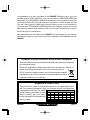
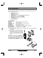
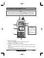
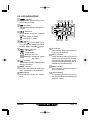
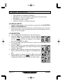
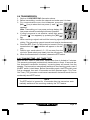
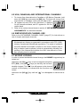
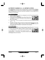
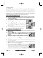
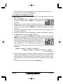
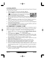
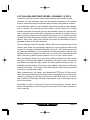
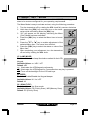
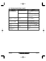
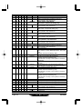
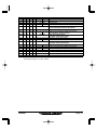
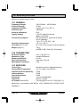
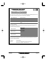
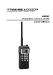
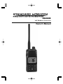
HX280E
VHF FM Marine Transceiver
Owner’s Manual
HX280E
Page 1
TABLE OF CONTENTS
1. GENERAL INFORMATION .................................................................................... 4
1.1 INTRODUCTION ........................................................................................... 4
2. ABOUT THIS RADIO ............................................................................................ 4
2.1 ABOUT THE VHF MARINE BAND ........................................................... 4
3. ACCESSORIES ....................................................................................................... 5
2.1 PACKING LIST ............................................................................................. 5
2.2 OPTIONS ...................................................................................................... 5
4. GETTING STARTED .............................................................................................. 6
4.1 RADIO CARE ................................................................................................ 6
4.2 BATTERIES AND CHARGERS .................................................................. 6
4.2.1 BATTERY SAFETY ........................................................................... 6
4.2.2 BATTERY INSTALLATION / REMOVAL ........................................... 8
4.2.3 BATTERY CHARGING ...................................................................... 8
4.3 INSTALLATION OF OPTION ........................................................................ 9
4.3.1 FBA-40 ALKALINE BATTERY CASE ................................................ 9
5. CONTROLS AND INDICATORS ........................................................................ 10
5.1 CONTROLS AND SWITCHES ................................................................. 10
5.2 INDICATORS ............................................................................................... 13
6. BASIC OPERATION ............................................................................................ 14
6.1 PROHIBITED COMMUNICATIONS .......................................................... 14
6.2 INITIAL SETUP .......................................................................................... 14
6.3 RECEPTION ............................................................................................... 14
6.4 TRANSMISSION ......................................................................................... 15
6.4.1 TRANSMIT TIME-OUT TIMER (TOT) ............................................. 15
6.5 USA, CANADIAN, AND INTERNATIONAL CHANNELS ........................ 16
6.6 SIMPLEX/DUPLEX CHANNEL USE ........................................................ 16
6.7 KEYPAD LOCKING .................................................................................... 16
6.8 PRESET CHANNELS (0 ~ 9): INSTANT ACCESS ................................. 17
6.8.1 PROGRAMMIMG ............................................................................ 17
6.8.2 OPERATION .................................................................................... 17
6.9 SCANNING ................................................................................................. 18
6.9.1 SELECTING THE SCAN TYPE ...................................................... 18
6.9.2 MEMORY SCANNING (M-SCAN) ................................................... 18
6.9.3 PRIORITY SCANNING (P-SCAN) .................................................. 19
6.10 DUAL WATCH ............................................................................................ 20
6.11 EMERGENCY (CHANNEL 16 USE) ......................................................... 20
6.12 CALLING ANOTHER VESSEL (CHANNEL 16 OR 9) ........................... 21
6.13 OPERATING ON CHANNEL 13 .............................................................. 22
6.14 OPERATING ON CHANNEL 67 .............................................................. 22
7. MENU (“SET”) MODE .......................................................................................... 23
8. MAINTENANCE .................................................................................................... 24
8.1 GENERAL ................................................................................................... 24
8.2 REPLACEMENT PARTS ........................................................................... 24
8.3 TROUBLESHOOTING CHART ................................................................. 25
9. VHF MARINE CHANNEL ASSIGNMENT ......................................................... 26
10. SPECIFICATIONS ................................................................................................. 30
10.1 GENERAL ................................................................................................... 30
10.2 TRANSMITTER ........................................................................................... 30
10.3 RECEIVER .................................................................................................. 30
Page 2
HX280E
Congratulations on your purchase of the HX280E! Whether this is your first
portable marine VHF transceiver, or if you have other STANDARD HORIZON
equipment, the STANDARD HORIZON organization is committed to ensuring
your enjoyment of this high performance transceiver, which should provide
you with many years of satisfying communications even in the harshest of
environments. STANDARD HORIZON technical support personnel stands
behind every product sold, and we invite you to contact us should you require
technical advice or assistance.
We appreciate your purchase of the HX280E, and encourage you to read this
manual thoroughly, so as to learn and fully understand the capabilities of the
HX280E.
Disposal of your Electronic and Electric Equipment
Products with the symbol (crossed-out wheeled bin) cannot be disposed
as household waste.
Electronic and Electric Equipment should be recycled at a facility capable of handling these items and their waste byproducts.
In EU countries, please contact your local equipment supplier
representative or service center for information about the waste
collection system in your country.
Attention in Case of Use
This transceiver works on frequencies which are not generally permitted. For frequency allocation, apply for a licence at your local spectrum
management authority. For actual
List of the practicable area
usage contact your dealer or sales AUT BEL BGR CYP CZE DEU DNK
shop in order to get your trans- ESP EST FIN FRA GBR GRC HUN
IRL
ITA LTU LUX LVA MLT NLD
ceiver adjusted to the allocated fre- POL PRT ROM SVK SVN SWE CHE
quency range.
ISL
LIE NOR
HX280E
Page 3
1. GENERAL INFORMATION
1.1 INTRODUCTION
The HX280E is a Submersible 5-Watt portable two way marine transceiver.
The transceiver has all allocated USA, International, or Canadian channels. It
has emergency channel 16 which can be immediately selected from any channel by pressing the [16/9] key.
The HX280E includes the following features: Memory Scanning, Priority Scanning, easy-to-read large LCD display, EEPROM memory back-up, Battery Life
displayed on LCD, and a transmit Time-Out Timer (TOT).
The HX280E transmitter provides a full 5 Watt of transmit power and also is
selectable to 1 Watt to assist the user in ensuring maximum battery life.
2. ABOUT THIS RADIO
2.1 ABOUT THE VHF MARINE BAND
WARNING
The radio frequencies used in the VHF marine band lie between 156
and 158 MHz. The marine VHF band provides communications over
distances that are essentially “Line of sight” Actual transmission range
depends much more on antenna type, gain and height than on the power
output of the transmitter. On a fixed mount 25 W radio transmission
expected distances can be greater than 15 miles, for a portable 5 W
radio transmission the expected distance can be greater than 5 miles in
“Line of sight”.
The user of a Marine VHF radio is subject to severe fines if the radio is
used on land. The reasoning for this is you may be near an inland waterway, or propagation anomalies may cause your transmission to be heard
in a waterway. If this occurs, depending upon the marine VHF channel
on which you are transmitting, you could interfere with a search and
rescue case, or contribute to a collision between passing ships. For
VHF Marine channel assignments refer to page 32 section 10.
Page 4
HX280E
3. ACCESSORIES
3.1 PACKING LIST
When the package containing the transceiver is first opened, please check it
for the following contents:
HX280E Transceiver
CAT460 Antenna
FNB-V105LI 7.4 V, 1650 mAh Li-Ion Battery Pack
CD-46 Charger Cradle for HX280E
PA-48C/U AC AC Adapter for CD-46
CLIP-920 Belt Clip
Owner’s Manual
3.2 OPTIONS
CN-3
CD-46
FNB-V105LI
FBA-40
E-DC-19A1
PA-48B/C/U2
Radio-to-Ship’s-Antenna Adapter
Charger Cradle
7.4 V, 1650 mAh Li-Ion Battery Pack
Alkaline Battery Case
DC Cable with 12 V Cigarette Lighter Plug
AC Adapter for the CD-46
1: E-DC-19A supply voltage 10.4 V ~ 14.4 VDC only. Fuse rating of 3A only
to be used.
2: “B” suffix is for use with 120 VAC
(Type-A plug), “C” suffix is for use with
230 VAC (Type-C plug), and “U” suffix is for use with 230 VAC (Type-BF
plug).
Note: Before operating the HX280E for
the first time, it is recommended that the
battery be charged. Please see section
“4.2.3 BATTERY CHARGING” for details.
HX280E
Page 5
4. GETTING STARTED
4.1 RADIO CARE
CAUTION
Before following the instructions below, insure the battery pack is in place
and firmly tightened. Care must be taken if the radio was dropped and a
close inspection may be needed to insure the radio case and gaskets
are in adequate condition.
Clean the radio with fresh water after exposure to salt water by rinsing the
radio under a sink faucet or by dunking the radio in a bucket of fresh water.
After washing, use a soft cloth and thoroughly dry all parts of the radio. This is
to keep the rubber switches and speaker grill clean and in top operating condition.
CAUTION
There is rare case that water is in between the radio and battery pack. In
this case, the radio and battery pack keep the submersible performance
individually. However, remove the battery pack from the radio, then clean
the radio and battery pack individually by a procedures described above.
4.2 BATTERIES AND CHARGERS
If the radio has never been used, or its charge is depleted, it may be charged
by connecting the CD-46 Charger Cradle with the PA-48C/U AC Adapter, as
shown in the illustration on page 8. The PA-48C/U will charge a completely
discharged FNB-V105LI battery pack in about 6 hours.
The FNB-V105LI is a high performance Li-Ion battery providing high capacity
in a compact package.
CAUTION
To avoid risk of explosion and injury, FNB-V105LI battery pack should
only be removed, charged or recharged in non-hazardous environments.
4.2.1 BATTERY SAFETY
Battery packs for your transceiver contain Li-Ion batteries. This type of battery
stores a charge powerful enough to be dangerous if misused or abused, especially when removed from the transceiver. Please observe the following precautions:
Page 6
HX280E
DO NOT SHORT BATTERY PACK TERMINALS: Shorting the terminals that
power the transceiver can cause sparks, severe overheating, burns, and battery cell damage. If the short is of sufficient duration, it is possible to melt
battery components. Do not place a loose battery pack on or near metal surfaces or objects such as paper clips, keys, tools, etc. When the battery pack is
installed on the transceiver, the terminals that transfer current to the transceiver are not exposed. The terminals that are exposed on the battery pack
when it is mounted on the transceiver are charging terminals only and do not
constitute a hazard.
DO NOT INCINERATE: Do not dispose of any battery in a fire or incinerator.
The heat of fire may cause battery cells to explode and/or release dangerous
gases.
Battery Maintenance
For safe and proper battery use, please observe the following:
Battery packs should be charged only in non-hazardous environments;
Use only STANDARD HORIZON-approved batteries;
Use only a STANDARD HORIZON approved charger. The use of any
other charger may cause permanent damage to the battery.
Follow charging instructions provided with the chargers.
Keep the battery contacts clean.
Battery Storage
Store the batteries in a cool place to maximize storage life. Since batteries are
subject to self-discharge, avoid high storage temperatures that cause large
self-discharge rates. After extended storage, a full recharge is recommended.
Battery Recycling
DO NOT PLACE USED BATTERIES IN YOUR REGULAR TRASH!
LI-ION BATTERIES MUST BE COLLECTED, RECYCLED OR DISPOSED
OF IN AN ENVIRONMENTALLY SOUND MANNER.
The incineration, land filling or mixing of Li-Ion batteries with the municipal
solid waste stream is PROHIBITED BY LAW in most areas.
Return batteries to an approved Li-Ion battery recycler. This may be where
you purchased the battery.
Contact your local waste management officials for other information regarding
the environmentally sound collection, recycling and disposal of Li-Ion batteries.
HX280E
Page 7
4.2.2 BATTERY INSTALLATION/REMOVAL
To install the battery pack, hold the transceiver with your left hand, so your
palm is over the speaker and your thumb is on the top of the belt clip. Insert
Push the bottom side of
the battery pack into the batthe battery pack
tery compartment on the back
Clip
of the radio while tilting the Belt
e Belt
Tilt th
Clip outward, then push the
ack
ttery P
bottom side of the battery pack
the Ba
Insert
until the battery pack locks with
the Battery Pack Latch.
To remove the battery, turn the radio off. Slide the Battery Pack Latch on
the bottom of the radio, then slide the battery downward and out from the
radio while holding the Belt Clip.
4.2.3 BATTERY CHARGING
1. Turn the transceiver off.
2. PA-48C/U: Insert the DC plug from the
PA-48C/U into the DC jack on the CD-46
side panel, then plug the PA-48C/U into
the AC line outlet.
E-DC-19A: Insert the DC plug from the
PA-48C/U
E-DC-19A into the DC jack on the CD-46
side panel, then insert the 12 V DC connector into a suitable DC supply (10 - 14
VDC).
3. Insert the HX280E (with the battery pack)
into the CD-46; the antenna should be at
CD-46
the left side when viewing the charger
from the front.
4. If the HX280E is inserted correctly, the Red “CHARGING” indicator will
glow. A fully-discharged pack will be charged completely in approximately
6 hours.
5. When charging is completed, the red LED indicator will change to green.
Remove the transceiver from the CD-46, and unplug the NC-90C/U from
the AC line outlet (PA-48C/U) or unplug the E-DC-19A from the DC supply
(E-DC-19A).
CAUTION
The CD-46 is NOT designed to be waterproof. Do not attempt to charge
in water hazardous locations.
Page 8
HX280E
NOTE
The CD-46 is only designed for the charging of the HX280E’s battery,
and is not suitable for other purposes. The CD-46 may contribute noise
to TV and radio reception in the immediate vicinity, so we do not recommend its use adjacent to such device.
4.3 INSTALLATION OF OPTION
4.3.1 FBA-40 ALKALINE BATTERY CASE
FBA-40 is a battery case that holds six LR6 size Alkaline batteries and is used
with the HX280E transceiver. When the FBA-40 is installed into the HX280E
the radio can withstand immersion in water up to 3.3ft for 30 minutes.
1. On the FBA-40, remove the battery case cover ( ).
2. Slide the six LR6 size Alkaline batteries into the FBA-40 Battery Case with
the Negative (–) side of the batteries touching the spring connections inside the FBA-40 Battery Case.
3. Attach the battery cover to the FBA-40 Battery Case while being careful so
that o-ring is not twisted.
4. Insert the FBA-40 Battery Case into the battery compartment on the back
of the HX280E transceiver while tilting the Belt Clip outward, then push the
bottom side of the FBA-40 Battery Case until the Battery Case locks with
the Battery Pack Latch.
HX280E
Page 9
5. CONTROLS AND INDICATORS
5.1 CONTROLS AND SWITCHES
NOTE
This section defines each control of the transceiver. For detailed operating instructions, refer to section 6 “BASIC OPERATION”. Refer to illustrations for the location of the following controls, switches, and connections.
NOTE
When transmitting,
position your mouth
about 1.0 ~ 2.5 cm
away from the small
mic hole.
Speak slowly and
clearly into the microphone.
ANT Jack (Top Panel)
The supplied CAT460 flexible antenna is attached here.
POWER Switch/VOLUME Control (VOL)
Turns the transceiver on and off as well as adjusts the speakers audio
volume.
Turn this knob clockwise to turn the radio on and increase the speakers
audio volume.
Turn fully counter-clockwise to turn the radio off.
Page 10
HX280E
PTT (PUSH-TO-TALK) Switch
When pushed activates the transmitter.
LCD Display
This display shows current operating conditions, as indicated on the page
13.
Keypad
[SQL] Key
Press this key to activate the squelch adjusting mode. Press the [] or []
key to adjust the squelch threshold level.
Press and hold this key for 3 seconds to open the squelch, allowing you to
monitor the operating channel. Release the key to resume normal (quiet)
monitoring.
[SCAN] Key
Starts scanning and priority scanning of programmed channels.
[(UP)] Key
Press the key momentarily to increase the channel one step. Hold the key
down to increase the channel continuously.
Secondary use:
Used to adjust the squelch threshold level up after the [SQL] key is pressed.
[(DOWN)] Key
Press the key momentarily to decrease the channel one step. Hold the key
down to decrease the channel continuously.
Secondary use:
Used to adjust the squelch threshold level down after the [SQL] key is
pressed.
[DW] Key
Press this key to activate the Dual Watch feature. A “
” icon will appear
on the upper left of the display when the Dual Watch feature is activated.
Secondary use:
When the [16/9] key is held and the [DW] key is pressed, the radio will
change the marine band between the International, Canadian, and USA
channels.
HX280E
Page 11
[MEM] Key
Press this key to memorize the selected channel for scanning. When
pressed a “MEM” icon will be shown on the LCD display indicating the
channel has been saved to scan memory.
To delete the channel from scan memory, select the channel and press
this key until “MEM” is removed from the display.
[H/L( )] Key
Press this key to toggle the transmitter output power between “High” (5
Watts) and “Low” (1 Watt) power. This key does not function on the “Transmission Inhibited” and “Low power only” channels.
Secondary use:
Hold down this key to lock the keypad (except the [SQL], [H/L( )], and
PTT keys) so that they are not accidentally changed. The “ ” icon will
appear at the bottom right corner on the display, to indicate that the functions are locked. Hold down this key until the “ ” icon disappears to unlock the radio.
[16/9] Key
Pressing this key immediately recalls channel 16 from any channel location. Holding down this key recalls channel 9. Pressing this key again reverts to the previous selected working channel.
[PRESET] Key
Immediately recalls one of up to 10 user preset memories for each band
(shown as “0” - “9” on the LCD). Pressing this key repeatedly scrolls through
the preset memory channels.
Speaker
The internal speaker is located here.
Microphone
The internal microphone is located here.
When transmitting, position your mouth about 1.0 ~ 2.5 cm away from the
small mic hole. Speak slowly and clearly into the microphone.
Battery Pack Lock (Bottom side)
Slide the Battery Pack Lock to the “” position for battery removal.
Page 12
HX280E
5.2 LCD INDICATORS
“
” Indicator
This indicator appears when a signal is being received.
“
” Indicator
This indicator appears during transmission.
“ / ” Indicators
This indicator shows the TX output
power.
“ ”: High power (5 Watts)
“ ”: Low power (1 Watt).
“
” Indicator
When the “
” icon is shown on the
LCD, all keys are disabled except for
the PTT, [SQL], and [H/L( )] keys.
“
“
“
“
“
” Battery Indicator
”: Full battery
”: Lower battery
”: Battery is very low
(Blinking)”: Prepare to charge
the battery
“P” Indicator
This indicator shows the channel is
in the “Priority Channel”.
“
” Indicator
This indicator appears when the Dual
Watch is activated.
“U/I/C” Indicator
These indicators show the “band” of
operation for the particular channel.
“U” indicates the USA band; “I” indicates the International band; and “C”
indicates the Canadian band.
“MEM” Indicator
This indicator shows the channel is
in the transceiver’s “Scan Memory”.
“SCN” Indicator
This indicator appears when the
Scan is activated.
SQL Indicator
This indicator shows the squelch
level.
Channel Display
The operating channel is shown on
the LCD in both the transmission and
reception modes.
HX280E
Page 13
6. BASIC OPERATION
6.1 PROHIBITED COMMUNICATIONS
False distress or emergency messages:
Messages to “any boat” except in emergencies and radio tests;
Messages to or from a vessel on land;
Transmission while on land;
Obscene, indecent, or profane language.
6.2 INITIAL SETUP
1. Install the battery pack on the transceiver (see section “4.2.2 BATTERY
INSTALLATION/REMOVAL”).
2. Install the antenna onto the transceiver; hold the bottom end of the antenna, then screw it onto the mating connector on the transceiver until it is
snug. Do not over-tighten.
6.3 RECEPTION
1. Turn the VOL knob clockwise to turn the transceiver on.
2. Press the [SQL] key to activate the squelch adjusting
mode (The “SQL” indicator will blink). Press the [] key
until the “
” indicator will appear on the display,
[
then press the SQL] key again.
3. Turn up the VOL knob until the noise or audio from the speaker is at a
comfortable level.
4. Press the [SQL] key, then press the [ ] key until the
random noise disappears. This state is known as the
“Squelch Threshold”.
5. Press the [] or [] key to select the desired channel.
Refer to the channel chart on page 27 for available channels.
6. When a signal is received, adjust the VOL knob to the
desired listening level. The “
” indicator in the LCD
is displayed indicating that the channel is being used.
Page 14
HX280E
6.4 TRANSMISSION
1. Perform “6.3 RECEPTION” discussion above.
2. Before transmitting, monitor the channel and make sure it is clear.
3. For communications over short distances, press the
[H/L( )] key to select the Low power (1 watt: “ ” icon
appears).
Note: Transmitting on Low power prolongs battery life.
Low power should be selected whenever possible.
4. If using Low power is not effective, select High power
(5 watts: “ ” icon appears) by pressing the [H/L( )]
key.
5. When receiving a signal, wait until the incoming signal stops before transmitting. The transceiver cannot transmit and receive simultaneously.
6. Press the PTT (Push-To-Talk) switch to transmit. During
” indicator will appear on the distransmission, the “
play.
7. Position your mouth about 1.0 ~ 2.5 cm away from the
mic hole. Speak slowly and clearly into the microphone.
8. When the transmission is finished, release the PTT switch.
6.4.1 TRANSMIT TIME - OUT TIMER (TOT)
While the PTT switch is held down, transmission time is limited to 5 minutes.
This prevents prolonged (unintentional) transmissions. About 10 seconds before automatic transmitter shutdown, a warning beep will sound from the
speaker. The transceiver automatically switches to the receiving mode, even if
the PTT switch is held down. Before transmitting again, the PTT switch must
first be released, then wait 10 seconds and then pressed again. This TimeOut-Timer (TOT) prevents a continuous transmission that would result from an
accidentally stuck PTT switch.
NOTE
The PTT switch is ignored for 10 seconds after the transceiver automatically switches to the receiving mode by the TOT feature.
HX280E
Page 15
6.5 USA, CANADIAN, AND INTERNATIONAL CHANNELS
1. To change from International to Canadian or US Marine Channels, hold
down the [16/9] key and press the [DW] key. The band will change from
International, to Canadian, and to US with each press.
2. “U” appears on the LCD for the USA band, “I” appears
for the International band, and “C” appears for the Canadian band
3. Refer to the marine channel charts in section 9 “VHF MARINE CHANNEL
ASSIGNMENTS” for allocated channels.
6.6 SIMPLEX/DUPLEX CHANNEL USE
Refer to the VHF MARINE CHANNEL CHART (page 27) for instructions on
use of simplex and duplex channels.
NOTE
All channels are factory-programmed in accordance with FCC (USA),
Industry Canada and International regulations. The mode of operation
cannot be altered from simplex to duplex or vice-versa. Simplex (ship to
ship) or duplex (marine operator) mode is automatically activated, depending on the channel and whether the USA, International or Canadian operating band is selected.
6.7 KEYPAD LOCKING
In order to prevent accidental channel change, the HX280E’s keypad may be
locked out.
Hold down the [H/L( )] key to lock the keypad (except the
PTT, [SQL], and [H/L( )] keys) so that they are not accidentally changed. The “
” icon will appear on the channel
number of the display, to indicate that the functions are
locked.
Hold down the [H/L(
dio.
Page 16
)] key until the “
” icon disappears to unlock the ra-
HX280E
6.8 PRESET CHANNELS (0 ~ 9): INSTANT ACCESS
Ten user assigned channels can be programmed for instant access. Pressing
the [PRESET] key activates the user assigned channel bank. If the [PRESET]
key is pressed and no channels have been assigned, an alert beep will be
emitted from the speaker.
6.8.1 PROGRAMMING
1. Select the desired channel to be assigned into the Preset Channel Bank
using the [] or [] key.
2. Press and hold the [PRESET] key until the Preset Channel Number “0” is shown at the right of the channel number on the display.
3. Repeat steps 1 and 2 to program the desired channels into Preset Channels “1” ~ “9”.
4. To delete a Preset Channel, select the Preset Channel Number to be deleted using the [] or [] key, then press and hold the [PRESET] key until
the Preset Channel Number is removed from the display.
6.8.2 OPERATION
Pressing the [PRESET] key will toggle between Preset Channels “0” through
“9” and the last selected “regular” channel. Preset Channel
“0” is represented by “0” to the right of the channel number
on the display for one second, and preset channel “1” is
represented by “1” and so forth. The preset channel number
will disappear after one second.
HX280E
Page 17
6.9 SCANNING
The HX280E allows the user to select the scan type from “Memory Scan” or
“Priority Scan”. “Memory Scan” scans the channels that were programmed
into memory. “Priority Scan” scans the channels that were programmed into
memory with the priority channel (Channel 16). When an incoming signal is
detected on one of the channels during scan, the radio will pause on that
channel, allowing you to listen to the incoming transmission.
6.9.1 SELECTING THE SCAN TYPE
1. Turn the transceiver off by rotating the VOL knob fully counter-clockwise.
2. Hold down the [SQL] key, and then turn on the transceiver while still holding down the [SQL] key.
3. “SEt” will appear on the display, indicating the Menu
(“Set”) Mode has been activated.
4. Press the [SQL] key, repeatedly if necessary to
select the Menu item “SC”.
5. Press the [] or [] key to select “PS (Priority Scan)” or
“MS (Memory Scan)”. The factory default is “PS
(Priority Scan)”.
6. After completing your selection, turn the transceiver off and on by rotating the VOL knob.
6.9.2 MEMORY SCANNING (M-SCAN)
1. Select the desired channel to be included in the scan memory using the
[] or [] key.
2. Press the [ MEM ] key to store the channel into the
transceiver’s scan memory. “MEM” will be displayed on
the LCD.
3. Repeat steps 1 and 2 for all the channels to be scanned.
4. To delete a channel from the transceiver’s scan memory, select the memorized channel, then press the [MEM] key to delete the channel from scan
memory.
5. All channels programmed remain in the transceiver’s scan memory even if
the power is turned off.
6. Adjust the SQL level until background noise is eliminated by pressing the
[SQL] key followed by the [] / [] key.
7. To start scanning, press the [SCAN] key. The scan proceeds from the lowest to the highest programmed channel and stops scanning when a transmission is received.
Scanning will resume when the incoming signal disappears at the end of the transmission. The “MEM” and “SCN” icon will apPage 18
HX280E
pear at the left of the channel number on the display during scanning.
8. To stop the scan, press the [SCAN] key.
6.9.3 PRIORITY SCANNING (P-SCAN)
1. Select the desired channel to be included in the scan memory using the
[] or [] key.
2. Press the [ MEM ] key to store the channel into the
transceiver’s scan memory. “MEM” will be displayed on
the LCD.
3. Repeat steps 1 and 2 for all the channels to be scanned.
4. To delete a channel from the transceiver’s scan memory, select the memorized channel, then press the [MEM] key to delete the channel from scan
memory.
5. All channels programmed remain in the transceiver’s scan memory even if
the power is turned off.
6. Adjust the Squelch Level until background noise is eliminated by pressing
the [SQL] key followed by the [] / [] key.
7. To start scanning, press the [SCAN] key. A “SCN” icon and blinking “P” and
“MEM” icons will appears at the left of the channel number on the display
during scanning. The scan proceeds between the memorized channels and the Priority Channel (Channel 16).
As an example of priority scanning, let us say that marine channels “06”, “07”, and “08” are memorized in the
transceiver’s scan memory. Priority scanning will proceed in the following
sequence:
[CH06] (CH16) [CH07] (CH16) [CH08] (CH16) [CH06] (CH16) [CH07] .....
: Priority Channel
4. Even when the transceiver stops and listens to the signal of a programmed
channel, the transceiver will “dual watch” between this channel and the
priority channel. This allows the radio to be able to receive calls on channel 16 (priority channel) even when the radio is receiving on another channel.
5. To stop the Priority Scanning, press the [SCAN] key.
HX280E
Page 19
6.10 DUAL WATCH
The Dual Watch feature allows the radio watch the Priority Channel “Channel
16” and one other channel.
1. Select the desired channel using the [] or [] key.
2. Press the [DW] key to activate the Dual Watch feature. A
“
” icon will appear on the upper left of the display
when the Dual Watch feature is activated.
3. When a transmission is received on the “Priority Channel”, the radio receives the “Priority Channel” until the incoming signal disappears.
4. When a transmission is received on the “Priority Channel”, the radio receives the “Priority Channel” until the incoming signal disappears.
5. The Dual Watch feature will resume when the incoming signal disappears
at the end of the transmission.
6. To stop the Dual Watch feature and return to normal operation, press and
hold the [SCAN(DW)] key for two seconds again.
6.11 EMERGENCY (CHANNEL 16 USE)
Channel 16 is known as the Hail and Distress Channel. An emergency may be
defined as a threat to life or property. In such instances, be sure the transceiver is on and set to “Channel 16”. Then use the following procedure:
1. Press the PTT (Push-To-Talk) switch and say “Mayday, Mayday, Mayday.
This is _____, _____, _____” (your vessel’s name).
2. Then repeat once: “Mayday, _____” (your vessel’s name).
3. Now report your position in latitude/longitude, or by giving a true or magnetic bearing (state which) to a well-known landmark such as a navigation
aid or geographic feature such as an island or harbor entry.
4. Explain the nature of your distress (sinking, collision, aground, fire, heart
attack, life-threatening injury, etc.).
5. State the kind of assistance your desire (pumps, medical aid, etc.).
6. Report the number of persons aboard and condition of any injured.
7. Estimate the present seaworthiness and condition of your vessel.
8. Give your vessel’s description: length, design (power or sail), color and
other distinguishing marks. The total transmission should not exceed 1
minute.
9. End the message by saying “OVER”. Release the PTT switch and listen.
10. If there is no answer, repeat the above procedure. If there is still no response, try another channel.
Page 20
HX280E
6.12 CALLING ANOTHER VESSEL (CHANNEL 16 OR 9)
Channel 16 may be used for initial contact (hailing) with another vessel.
However, its most important use is for emergency messages. This channel
must be monitored at all times except when actually using another channel.
It is monitored by the U.S. and Canadian Coast Guards and by other vessels.
Use of channel 16 for hailing must be limited to initial contact only. Calling
should not exceed 30 seconds, but may be repeated 3 times at 2-minute intervals. In areas of heavy radio traffic, congestion on channel 16 resulting from its
use as a hailing channel can be reduced significantly in U.S. waters by using
Channel 9 as the initial contact (hailing) channel for non-emergency communications. Here, also, calling time should not exceed 30 seconds but may be
repeated 3 times at 2-minute intervals.
Prior to making contact with another vessel, refer to the channel charts in this
manual, and select an appropriate channel for communications after initial
contact. For example, Channels 68 and 69 of the U.S. VHF Charts are some of
the channels available to non-commercial (recreational) boaters. Monitor your
desired channel in advance to make sure you will not be interrupting other
traffic, and then go back to either channel 16 or 9 for your initial contact.
When the hailing channel (16 or 9) is clear, state the name of the other vessel
you wish to call and then “this is” followed by the name of your vessel and
your Station License (Call Sign). When the other vessel returns your call, immediately request another channel by saying “go to”, the number of the other
channel, and “over”. Then switch to the new channel. When the new channel
is not busy, call the other vessel.
After a transmission, say “over”, and release the PTT (Push-To-Talk) switch.
When all communication with the other vessel is completed, end the last transmission by stating your Call Sign and the word “out”. Note that it is not necessary to state your Call Sign with each transmission, only at the beginning and
end of the contact.
Remember to return to Channel 16 when not using another channel. Some
radios automatically monitor Channel 16 even when set to other channels or
when scanning.
HX280E
Page 21
6.13 OPERATING ON CHANNEL 13
Channel 13 is used at docks, bridges and for maneuvering in port. Messages
on this channel must concern navigation only, such as meeting and passing in
restricted waters. In emergencies and when approaching blind river bends,
High power is allowed. Pressing the [H/L( )] key will change the power output from Low Power (1 Watt) to High (5 Watts). When you change from this
channel then return to it, low power will be automatically selected.
6.14 OPERATING ON CHANNEL 67
When channel 67 is used for navigational bridge-to-bridge traffic between ships,
Normal, High or Medium power may be used temporarily (in the USA band) by
pressing the [H/L( )] key. When you select this channel again, the transceiver will revert to low power.
Page 22
HX280E
7. MENU (“SET”) MODE
The HX280E’s Menu Mode allows a number of the HX280E operating parameters to be custom-configured for your operating requirements.
The Menu Mode is easy to activate and set, using the following procedure:
1. Turn the transceiver off by rotating the VOL knob fully counter-clockwise.
2. Hold down the [SQL] key, and then turn on the transceiver while still holding down the [SQL] key.
3. “SEt” will appear on the display, indicating the Menu
(“Set”) Mode has been activated.
4. Press the [SQL] key to select the Menu item to be adjusted.
5. Press the [ ] or [ ] key to enable adjustment of the
selected Menu item. The menu item will blink.
6. Press the [SQL] key to select the status or value of the
Menu item.
7. After completing your adjustment, turn the transceiver
off and on by rotating the VOL knob.
LP (LAMP MODE)
Function: Selects the Lamp illumination method for the LCD/
Keypad.
Available Values: on / kEY / oFF
Default: kEY
on: Illuminates the LCD/Keypad continuously.
kEY: Illuminates the LCD/Keypad for 5 seconds when any key is pressed.
oFF: Turns off the backlight for the LCD and keys.
bP (BEEP)
Function: Enable/Disable the Keypad beeper.
Available Values: HI / Lo / oFF
Default: HI
SC (SCAN TYPE)
Function: Selects the Scan mode.
Available Values: PS (Priority Scan) / MS (Memory Scan)
Default: PS (Priority Scan)
HX280E
Page 23
8. MAINTENANCE
8.1 GENERAL
The inherent quality of the solid-state components in STANDARD HORIZON
radios will provide many years of continuous use. Take the following precautions to prevent damage to the radio.
To prevent corrosion of electrical contacts and keep the water resistance,
keep the microphone connected or the jack covered at all times.
Never key the transmitter unless an antenna or suitable dummy load is
connected to the antenna receptacle.
Ensure that the input voltage does not exceed the value specified in your
Owner’s Manual.
Use only STANDARD HORIZON-approved accessories and replacement
parts.
In the unlikely event of serious problems, please contact your Dealer.
8.2 REPLACEMENT PARTS
Occasionally an owner needs a replacement part. These can be ordered from
STANDARD HORIZON authorized dealers.
Commonly requested parts, and their part numbers are listed below.
VOL Knob: RA1078700
CD-46 Charger Cradle: CB4777001
CAT460 Antenna: Q3000176
CLIP-920 Belt Clip: AAE51X001
11.2 FACTORY SERVICE
In the unlikely event that the radio fails to perform or needs servicing, please
contact your Dealer or STANDARD HORIZON authorized dealers.
Page 24
HX280E
8.3 TROUBLESHOOTING CHART
SYMPTOM
The [SCAN(DW)] key
does not start the scan.
PROBABLE CAUSE
REMEDY
No channels memorized.
Use the [MEM] key to enter desired
channels into the transceiver’s
memory.
Squelch is not adjusted.
Adjust the squelch to threshold or
to the point where noise just disappears. Further adjustment of the
squelch control may eliminate incoming signals.
Cannot select between
USA, INTL, or Canadian
bands.
Proper operation not
followed.
HOLD down the [ 16/9 ] key and
press the [DW] key.
Speaker audio is not
heard when the [SQL]
key is press and held.
Low battery.
Charge battery. Refer to section
4.2.3 of this manual.
Audio volume level is too low.
Turn the VOL knob clockwise.
Some keys do not
operate.
Key Lock is on.
Turn Key Lock off. Refer to section
5.1 of this manual ([H/L( )] key).
Cannot select keylock
function.
Proper operation not
followed.
Hold down the [H/L(
seconds.
Charging indicator on
CD-46 does not
illumininate.
Defective battery FNB-V105LI.
Contact your Standard Horizon
dealer.
HX280E
)] key for 2
Page 25
9. VHF MARINE CHANNEL ASSIGNMENTS
Tables on the following pages list the VHF Marine Channel assignments for
U.S.A. and International use. Below are listed some data about the charts.
1. VTS. Where indicated, these channels are part of the U.S. Coast Guard’s
Vessel Traffic System.
2. Alpha channel numbers, that is, channel numbers followed by the letter A
(such as Channel 07A) are simplex channels on the U.S.A. or Canadian
channel assignments whose counterparts in the International assignments
are duplex channels. International channels do not use “alpha” numbers.
If you call the Coast Guard on Channel 16, they will sometimes ask you to
“go to channel 22 Alpha.” This is a channel assigned to U.S.A, and Canadian Coast Guards for handling distress and other calls. If your radio is set
for International operation you will go to Channel 22 instead of 22A, and
will not be able to communicate with the Coast Guard. To use Channel
22A, your radio must be set for USA or Canada operation, usually by a U/
I/C (USA/International/Canada) control or combination of controls. Channel 22 (without an “A”) is an International duplex channel for port operations. Some radios indicate an “A” adjacent to the alpha channels on the
display; on others “alpha” is not indicated but the proper channel is selected based on the U/I/C setting.
3. Bridge-to-Bridge channels (for example, Channel 13) are for use by bridge
operators on inter-coastal waterways and rivers. It is also used by marine
vessels in the vicinity of these bridges for navigation and for communicating with the bridge operators. Note that a limit of 1 Watt is specified for
these channels.
4. The S/D column on the chart indicates either S (simplex) or D (duplex). Simplex means transmitting and receiving on the same frequency. Only one party
at a time can talk, unlike a telephone. Be sure to say “over” and release your
microphone push-to-talk switch at the end of each transmission. Duplex operation involves the use of one frequency for transmitting and a separate frequency for receiving. On channels specified as duplex on the charts, correct
mode of operation is established automatically by your radio when you select a
channel; you cannot change the mode. And you still must release the push-totalk switch after each transmission in order to listen to the radio.
5. Channels normally used by recreational boaters are those that include the
term “non-commercial” in the Channel Use column of the chart. Some of
these are shared with other users and some are used only in certain geographic regions.
6. Marine vessels equipped with VHF radios are required to monitor Channel 16.
Page 26
HX280E
CH
01
01A
02
03
03A
04
U
C
X
X
X
X
X
04A
X
05
05A
06
07
X
X
X
X
07A
08
09
X
X
X
X
X
X
10
11
12
13
14
15
15
16
17
18
18A
19
19A
19A
20
X
X
X
X
X
X
X
X
X
X
X
20A
21
21A
22
22A
23
23A
24
25
26
27
28
X
X
X
X
X
X
X
X
X
X
X
X
X
X
X
X
X
X
X
X
X
X
X
HX280E
X
X
X
X
X
VHF MARINE CHANNEL CHART
I S/D
TX
RX
CHANNEL USE
X D 156.050 160.650 Public Correspondence (Marine Operator)
S
156.050
Port Operation and Commercial.
VTS in selected areas
X D 156.100 160.700 Public Correspondence (Marine Operator)
X D 156.150 160.750 Public Correspondence (Marine Operator)
S
156.150
U.S. Government Only, Coast Guard
X D 156.200 160.800 Public Correspondence (Marine Operator),
Port operation, ship movement
S
156.200
Pacific coast: Coast Guard, East Coast:
Commercial fishing
X D 156.250 160.850 Public Correspondence (Marine Operator),
Port operation, ship movement
S
156.250
Port operation. VTS in Seattle
X S
156.300
Inter-ship Sefety
X D 156.350 160.950 Public Correspondence (Marine Operator),
Port operation, ship movement
S
156.350
Commercial
X S
156.400
Commercial (Inter-ship only)
X S
156.450
Boater Calling channel, Commercial &
Non-commercial (Recreational)
X S
156.500
Commercial
X S
156.550
Commercial. VTS in selected areas.
X S
156.600
Port operation. VTS in selected areas.
X S
156.650
Inter-ship Navigation Safety (Bridge-to-bridge)
X S
156.700
Port operation. VTS in selected areas.
S
--156.750 Environmental (Receive only)
X S
156.750
Commercial, non-commercial, ship movement (1 W)
X S
156.800
International Distress, Safety and Calling
X S
156.850
State Controlled (1 W)
X D 156.900 161.500 Port operation, ship movement
S
156.900
Commercial
X D 156.950 161.550 Port operation, ship movement
S
156.950
US: Commercial
S
156.950
Coast Guard
X D 157.000 161.600 Canadian Coast Guard Only,
International: port operations and shipment
S
157.000
Port operation
X D 157.050 161.650 Port operation, ship movement
S
157.050
U.S. Government Only, Canadian Coast Guard
X D 157.100 161.700 Port operation, ship movement
S
157.100
US and Canadian Coast Guard Liaison and
Maritime Safety Information Broadcasts announced
on channel 16
X D 157.150 161.750 Public Correspondence (Marine Operator)
S
157.150
U.S. Government Only
X D 157.200 161.800 Public Correspondence (Marine Operator)
X D 157.250 161.850 Public Correspondence (Marine Operator)
X D 157.300 161.900 Public Correspondence (Marine Operator)
X D 157.350 161.950 Public Correspondence (Marine Operator)
X D 157.400 162.000 Public Correspondence (Marine Operator)
Page 27
CH
60
61
U
C
X
61A
X
X
62
62A
X
63
63A
X
64
64A
X
X
X
X
65A
66
X
X
66A
67
X
X
X
X
68
69
X
X
X
X
70
X
X
71
X
X
72
73
X
X
X
X
74
X
X
75
76
77
77
78
X
X
X
X
X
X
78A
79
79A
X
X
X
X
65
Page 28
VHF MARINE CHANNEL CHART
I S/D
TX
RX
CHANNEL USE
X D 156.025 160.625 Public Correspondence (Marine Operator)
X D 156.075 160.675 Public Correspondence (Marine Operator),
Port operation, ship movement
S
156.075
Public Coast: Coast Guard;
East Coast: commercial fishing only
X D 156.125 160.725 Public Correspondence (Marine Operator),
Port operation, ship movement
S
156.125
Public Coast: Coast Guard;
East Coast: commercial fishing only
X D 156.175 160.775 Public Correspondence (Marine Operator),
Port operation, ship movement
S
156.175
Port Operation and Commercial.
VTS in selected areas.
X D 156.225 160.825 Public Correspondence (Marine Operator),
Port operation, ship movement
S
156.225
Public Correspondence (Marine Operator),
Port operation, ship movement
X D 156.275 160.875 Public Correspondence (Marine Operator),
Port operation, ship movement
S
156.275
Port Opeations
X D 156.325 160.925 Public Correspondence (Marine Operator),
Port operation, ship movement
S
156.325
Port Operations
X S
156.375
US: Commercial. Used for Bridge-to-bridge com
muni-cations in lower Mississippi River. Inter-ship
only,
Canada: Commercial fishing, S&R
X S
156.425
Non-commercial (Recreational)
X S
156.475
US: Non-commercial (Recreational),
Canada: Commercial fishing only,
International: Inter-ship, Port opertions and Ship
movement
X S
156.525
Digital selective calling (voice communications not
allowed)
X S
156.575
US, Canada: Non-commercial (Recreational),
International: Port opertions and Ship movement
X S
156.625
Non-commercial (Inter-ship only)
X S
156.675
US: Port Operations,
Canada: Commercial fish ing only,
International: Inter-ship, Port opertions and Ship
movement
X S
156.725
US: Port Operations,
Canada: Commercial fishing only,
International: Inter-ship, Port opertions and Ship
movement
X S
156.775
Port Operations (Inter-ship only) (1W)
X S
156.825
Port Operations (Inter-ship only) (1W)
S
156.875
Port Operations (Inter-ship only) (1W)
X S
156.875
Port Operations (Inter-ship only)
X D 156.925 161.525 Public Correspondence (Marine Operator),
Port operation, ship-movement
S
156.925
Non-commercial (Recreational)
X D 156.975 161.575 Port operation and Ship movement
S
156.975
Commercial
HX280E
VHF MARINE CHANNEL CHART
I S/D
TX
RX
CHANNEL USE
X D 157.025 161.625 Port operation, ship movement
X X
S
157.025
Commercial
X D 157.075 161.675 Port operation, ship movement
X
S
157.075
U.S. Government Only Environmental protection operations.
81A
X
S
157.075
Canadian Coast Guard Only
82
X D 157.125 161.725 Public Correspondence (Marine Operator),
Port operation, ship movement
82A X X
S
157.125
U.S. Government Only,
Canadian Coast Guard Only
83
X
D 157.175 161.775 Canadian Coast Guard Only
83
X D 157.175 161.775 Public Correspondence (Marine Operator)
83A X X
S
157.175
U.S. Government Only,
Canadian Coast Guard Only
84
X X X D 157.225 161.825 Public Correspondence (Marine Operator)
85
X X X D 157.275 161.875 Public Correspondence (Marine Operator)
86
X X X D 157.325 161.925 Public Correspondence (Marine Operator)
87
X X S
157.375
Port operation, ship movement
87A X
S
157.375
Public Correspondence (Marine Operator)
88
X X S
157.425
Port operation, ship movement
88A X
S
157.425
Commercial, Inter-ship Only
NOTE: Simplex channels, 3A, 21A, 23A, 61A, 64A, 81A, 82A and 83A CANNOT be lawfully used
by the general public in U.S.A. waters.
CH
80
80A
81
81A
U
HX280E
C
Page 29
10. SPECIFICATIONS
Performance specifications are nominal, unless otherwise indicated, and are
subject to change without notice.
10.1 GENERAL
Frequency Ranges:
Channel Spacing:
Frequency Stability:
Emission Type:
Antenna Impedance:
Supply Voltage:
Current Consumption:
Operating Temperature:
Case Size (W x H x D):
Weight (Approx.):
156.025 MHz - 162.000 MHz
25 kHz
±5 ppm (–20 °C to +60 °C)
16K0G3E
50 Ω
7.4V DC, Negative Ground
(Battery Terminal)
320 mA (Receive, Typical at AF MAX.)
50 mA (Standby)
1.6 A / 0.7 A (TX: 5 W / 1W)
–20 °C to +60 °C
56 x 133 x 27.5 mm (w/o knob & antenna)
310 g
(w/FNB-V105LI, Belt Clip, & Antenna)
10.2 TRANSMITTER
RF Power Output:
Modulation Type:
Maximum Deviation:
Spurious Emission:
Microphone Impedance:
5 W / 1 W (@7.4 V )
Variable Reactance
±5 kHz
Less than 0.25 µW
2 kΩ
10.3 RECEIVER
Circuit Type:
Intermediate Frequencies:
Adjacent Channel Selectivity:
Intermodulation:
Hum & Noise Ratio:
Sensitivity:
Selectivity:
AF Output (Internal SP):
Double-Conversion Superheterodyne
1st: 21.7 MHz, 2nd: 450 kHz
70 dB
68 dB
40 dB
1 µV for 20 dB SINAD
25 kHz (–70 dB)
700 mW @16 Ω for 10 % THD (@7.4 V)
Measured in accordance with EN301 178-2, EN300 698-3, EN301 843-2,
EN60950-1
Page 30
HX280E
Declaration of Conformity
We, Yaesu UK Ltd. declare under our sole responsibility that the following equipment complies with the essential requirements of the Directive 1999/5/EC.
Type of Equipment:
VHF Transceiver
Brand Name:
Model Number:
Manufacturer:
Address of Manufacturer:
STANDARD HORIZON
HX280E
Vertex Standard Co., Ltd.
4-8-8 Nakameguro Meguro-Ku, Tokyo 153-8644,
Japan
Applicable Standards:
This equipment is tested and conforms to the essential requirements of directive, as
included in following standards.
EN 301 178-2
Radio Standard:
EN 300 698-3
EN 301 843-2
EMC Standard:
EN 60950-1
Safety Standard:
The technical documentation as required by the Conformity Assessment procedures is
kept at the following address:
Company:
Address:
HX280E
Yaesu UK Ltd.
Unit 12, Sun Valley Business Park, Winnall Close
Winchester, Hampshire, SO23 0LB, U.K.
Page 31
YAESU MUSEN CO., LTD.
Tennozu Parkside Building
2-5-8 Higashi-Shinagawa, Shinagawa-ku, Tokyo 140-0002 Japan
YAESU USA, INC.
6125 Phyllis Drive, Cypress, CA 90630
YAESU UK LTD.
Unit 12, Sun Valley Business Park, Winnall Close
Winchester, Hampshire, SO23 0LB, U.K.
YAESU HK LTD.
Unit 1306-1308, 13F., Millennium City 2, 378 Kwun Tong Road,
Kwun Tong, Kowloon, Hong Kong
Printed in China.
Page 32
Copyright 2012
YAESU MUSEN CO., LTD.
All rights reserved.
No portion of this manual
may be reproduced
without the permission of
YAESU MUSEN CO., LTD.
E
M
0
3
8
N
2
0
6
HX280E