1
June 2008
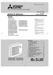
Air to Water (ATW) Heat pump,
Interface (I/F) and Flow temp. controller (FTC)
Technical manual
CONTENTS
1. What is ATW heat pump?.......................................................2
2. Heat pump unit_General information ...................................4
3. System design ......................................................................15
4. Interface (I/F) ........................................................................23
5. Flow temp. controller (FTC) .................................................55
6. Requirements........................................................................90
7. System example ...................................................................91
1
What is ATW heat pump?
1-1. Compare with conventional fossil fuel boiler
• Heat pumps produce water at 30°C – 60°C
• Ideal for underfloor heating
• Average underfloor heating circuit 35°C
• Fossil fuel boilers heat water to 80°C
• Flow temp in rads design temp approx 70°C
• Heat pumps can still be used with radiators
• Larger surface area to emit heat from lower temp water
1-2. Points to notice
1-2-1. Design (Radiator sizing)
• Careful consideration must be given to appropriate application of this technology to maximise its benefits – it will not suit all
properties, especially many retrofits
• Heat emitters may need to be larger
• Lower flow temperatures maximise COP
• Various regulations apply to the design and installation of such systems
• Because the flow temp. of heat pump is low compare to fossile fuel boiler, the temperature difference between the primary (flow
water) and secondary (room air) becomes little, it makes the heat emission little.
To emit the same amount of heat energy, it is needed to select the radiator that has a larger surface area.
Be especially careful of the surface area when you design the radiator.
1-2-2. Defrost
Note: Occasionally, vapor that is made by the defrost operation may seem as if smoke come up from the outdoor unit.
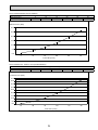
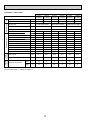
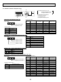
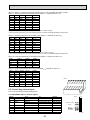
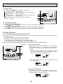
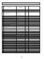
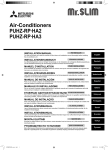
1-2-3. Water Pressure loss (for packaged type outdoor unit)
• Water pressure lose of the heat exchangers are as follows.
Be aware of the influence when you design total pipng system.
Hex for PUHZ-W50VHA (ACH30-30Plates)
Flow rate (L/min)
Pressure Loss (kPa)
5
1.7
Secondary (Water - side)
10
15
6.0
12.4
20
20.9
25
31.4
30
43.8
Pressure loss (kPa)
50
45
40
35
30
25
20
15
10
5
0
5
10
15
20
Flow rate (L/min)
2
25
30
Hex for PUHZ-W85VHA (ACH30-40Plates)
Flow rate (L/min)
Pressure Loss (kPa)
5
1.0
Secondary (Water - side)
10
15
3.6
7.5
20
12.5
25
18.8
30
26.2
Pressure loss (kPa)
30.0
25.0
20.0
15.0
10.0
5.0
0.0
5
10
15
20
25
30
Flow rate (L/min)
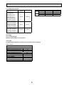
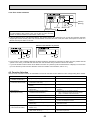
Hex for PUHZ-W112, 140VHA / YHA (ACH50-50Plates)
Flow rate (L/min)
Pressure Loss (kPa)
15
1.3
Secondary (Water - side)
30
45
4.9
10.9
60
19.3
75
29.9
90
42.8
Pressure loss (kPa)
45.0
40.0
35.0
30.0
25.0
20.0
15.0
10.0
5.0
0.0
15
30
45
60
Flow rate (L/min)
3
75
90
2
Heat pump unit_General information
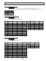
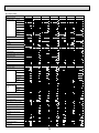
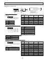
2-1. Line-up
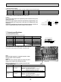
2-1-1. Outdoor unit for Air to water
(1) Packaged type: The Air to Water outdoor unit with a plate HEX (refrigerant-water) inside
Connectable models
Capacity
( HP )
2
3
4
5
Packaged models
1-phase
3-phase
PUHZ-W50VHA
—
PUHZ-W85VHA
—
—
—
—
—
ZUBADAN-Packaged models
1-phase
3-phase
—
—
—
—
—
PUHZ-HW112YHA
PUHZ-HW140VHA
PUHZ-HW140YHA
(2) Split type: The standard outdoor unit without a plate HEX (refrigerant-water) inside
Connectable models
Capacity
( HP )
2.5
3
4
5
6
Split Replace inverter models
1-phase
3-phase
PUHZ-RP60VHA3#1
—
PUHZ-RP71VHA3#1
—
PUHZ-RP100VHA3#1
PUHZ-RP100YHA3#1
PUHZ-RP125VHA2#2
PUHZ-RP125YHA2#2
PUHZ-RP140VHA2#2
PUHZ-RP140YHA2#2
Split ZUBADAN models
1-phase
3-phase
—
—
PUHZ-HRP71VHA(2)
—
PUHZ-HRP100VHA(2)
PUHZ-HRP100YHA(2)
—
PUHZ-HRP125YHA(2)
—
—
* Outdoor units (PUHZ-RP or PUHZ-P) other than the above-mentioned become possible by connecting TH5 ( 2-phase refrigerant temp. thermistor ) with the interface only for Air to Air use.
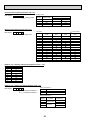
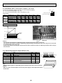
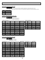
2-1-2. Air to Air application
INTER FACE MODEL NAME
OUTDOOR UNIT
AUTO
PUHZ-HRP
STEP *1
PUHZ-RP
PUHZ-P
SUZ-KA
PUH-P
MANUAL OUTDOOR UNIT
PUHZ-HRP
STEP *2
PUHZ-RP
35
—
VHA3
—
VA
—
35
—
VHA3
50
—
VHA3
—
VA
—
50
—
VHA3
60
—
VHA3
—
VA
—
60
—
VHA3
PAC-IF011B-E / PAC-IF010-E
71
100
125
140
VHA(2) V/YHA(2) YHA(2)
—
VHA3
V/YHA3 V/YHA2 V/YHA2
—
VHA2
VHA2
VHA2
VA
—
—
—
V/YHA
V/YHA
YHA
YHA
71
100
125
140
VHA
V(Y)HA
YHA
—
VHA3
V/YHA3 V/YHA2 V/YHA2
200
—
YHA2
YHA
—
MYA
200
—
YHA2
250
—
YHA2
YHA
—
MYA
250
—
YHA2
MANUAL STEP MODE is New function of INTER FACE (Fixed capacity = Compressor frequency (Hz) fixed mode) .
2 Phase (Gas/Liquid) pipe thermistor is required (TH5).
Also, Interface P.C.B. SW2-6 need to be set "OFF (No LEV self control mode)" .
<Old models : The models that are not described in the table above.>
*1: With(Auto-mode)+(SW2-6 is OFF)+(2phase thermistor), all A-control outdoor units are able to connect to PAC-IF010/
011B-E only for Air to Air use.
*2: With(Manual-mode)+(SW2-6 is OFF)+(2phase thermistor), from following RP type outdoor units are able to connect to
PAC-IF010/011B-E only for Air to Air use.
PUHZ-RP35V, 50V, 60V, 71V,100V/Y,125V/Y,140V/YHA2¹
PUHZ-RP200Y, 250YHA²
4
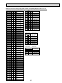
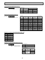
2-1-3. Reference manual
Outdoor unit
PUHZ-W50VHA
PUHZ-W85VHA
PUHZ-HW112YHA
PUHZ-HW140VHA
PUHZ-HW140YHA
PUHZ-RP60VHA3#1
PUHZ-RP71VHA3#1
PUHZ-RP100VHA3#1
PUHZ-RP125VHA2#2
PUHZ-RP140VHA2#2
PUHZ-RP100YHA3#1
PUHZ-RP125YHA2#2
PUHZ-RP140YHA2#2
PUHZ-HRP71VHA(2)
PUHZ-HRP100VHA(2)
PUHZ-HRP100YHA(2)
PUHZ-HRP125YHA(2)
Service
manual
Parts catalog
I/F
FTC
OCH439
OCB439
OC374
OC374
OCH425
OCB425
Type
cased
PCB only
cased
PCB only
2-2. Data
2-2-1. Packaged type
Refer to each model's service manual.
2-2-2. Split
[1] Specifications(Reference data(connect to plate heat exchanger))
Rating conditions
Nominal operating condition
Heating (A2/W35)
Outside air temperature (Dry-bulb)
Outside air temperature (Wet-bulb)
Water temperature (inlet/outlet)
Heating (A7/W35)
Outside air temperature (Dry-bulb)
Outside air temperature (Wet-bulb)
Water temperature (inlet/outlet)
Heating (A7/W45)
Outside air temperature (Dry-bulb)
Outside air temperature (Wet-bulb)
Water temperature (inlet/outlet)
+2:
+1:
+30/+35:
+7:
+6:
+30/+35:
+7:
+6:
+40/+45:
5
Model name
PAC-IF011B-E
PAC-IF010-E
PAC-IF021B-E
PAC-IF020-E
Parts catalog
OCB427
—
OCB427
—
(1) PUHZ-HRP • V/YHA2
Outdoor unit
Model name
PUHZ-HRP71VHA2
Power supply
(Phase, Voltage, Frequency)
Breaker size
Nominal water flow
Capacity
Heating
COP
(A2/W35)
Power input
Capacity
Heating
COP
(A7/W35)
Power input
Capacity
Heating
COP
(A7/W45)
Power input
Plate heat exchanger
ALFA LAVAL
ACH50
1[, 230V, 50Hz
A
L/min
kW
A: 50 mm
B: 466 mm
32
22.9
8.00
3.24
2.47
8.00
4.40
1.82
8.00
3.24
2.47
kW
kW
Model name
Power supply
(Phase, Voltage, Frequency)
1[, 230V, 50Hz /
3[, 400V, 50Hz
A
L/min
kW
40 / 16
32.1
11.20
3.02
3.71
11.20
4.26
2.63
11.20
3.24
3.46
11.20
2.40
4.67
kW
kW
kW
Outdoor unit
Model name
Power supply
(Phase, Voltage, Frequency)
Breaker size
Nominal water flow
Heating
Capacity
COP
(A2/W35)
Power input
Heating
Capacity
COP
(A7/W35)
Power input
Heating
Capacity
COP
(A7/W45)
Power input
A
L/min
kW
kW
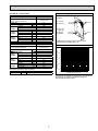
:
:
Water IN
Refrigerant pipng length from outdoor unit to
heat exchanger (Water HEX): 5m
Maximum outlet water temperature
65
60
55
50
45
40
-25
-20
-15
-10
-5
0
5
10
PUHZ-HRP125YHA2
3[, 400V, 50Hz
The performance might be decreased by the refrigerant
pipng length, insulation of refrigerant pipng and
heat exchanger (Water HEX).
Guaranteed operating range (Outdoor)
Heating
Cooling
H
A
Ref.OUT
(Heating)
Ambient temperature [°C]
16
40.1
14.00
2.70
5.19
14.00
4.22
3.32
14.00
3.20
4.38
kW
B
D
Maximum outlet water temptemperature [°C]
PUHZ-HRP100VHA2 /
PUHZ-HRP100YHA2
Water OUT
Ref.IN
(Heating)
W: 112 mm
H: 526 mm
D: 130 mm
50 plates
Outdoor unit
Breaker size
Nominal water flow
Heating
Capacity
COP
(A2/W35)
Power input
Heating
Capacity
COP
(A7/W35)
Power input
Heating
Capacity
COP
(A7/W45)
Power input
Heating
Capacity
COP
(A7/W55)
Power input
w
-25 ~ +35
-5 ~ +46
6
(2) PUHZ-RP • VHA3/YHA3(2)
Outdoor unit
Model name
PUHZ-RP60VHA3#1
Power supply
(Phase, Voltage, Frequency)
Breaker size
Nominal water flow
Capacity
Heating
COP
(A2/W35)
Power input
Capacity
Heating
COP
(A7/W35)
Power input
Capacity
Heating
COP
(A7/W45)
Power input
A
L/min
kW
A: 50 mm
B: 466 mm
25
20.1
6.80
2.94
2.31
7.00
4.29
1.63
7.00
3.27
2.14
kW
kW
kW
kW
kW
Model name
W:112 mm
H: 526 mm
D: 82 mm
30 plates
kW
kW
kW
Guaranteed operating range (Outdoor)
:
:
H
A
Ref.OUT
(Heating)
Water IN
Maximum outlet water temperature
65
Maximum outlet water temptemperature [°C]
25
22.9
7.50
2.92
2.57
8.00
4.21
1.90
8.00
3.20
2.50
kW
kW
B
Refrigerant pipng length from outdoor unit to
heat exchanger (Water HEX): 5m
1[, 230V, 50Hz
A
L/min
kW
Water OUT
Ref.IN
(Heating)
D
PUHZ-RP71VHA3#1
Power supply
(Phase, Voltage, Frequency)
Heating
Cooling
w
1[, 230V, 50Hz
Outdoor unit
Breaker size
Nominal water flow
Capacity
Heating
COP
(A2/W35)
Power input
Capacity
Heating
COP
(A7/W35)
Power input
Capacity
Heating
COP
(A7/W45)
Power input
Plate heat exchanger
ALFA LAVAL
ACH50
60
55
50
45
-11 ~ +35
-5 ~ +46
-10
-5
0
5
10
Ambient temperature [°C]
The performance might be decreased by the refrigerant
pipng length, insulation of refrigerant pipng and
heat exchanger (Water HEX).
7
Plate heat exchanger
ALFA LAVAL
ACH50
Outdoor unit
PUHZ-RP100VHA3#1 /
PUHZ-RP100YHA3#1
Model name
Power supply
(Phase, Voltage, Frequency)
Breaker size
Nominal water flow
Capacity
Heating
COP
(A2/W35)
Power input
Capacity
Heating
COP
(A7/W35)
Power input
Capacity
Heating
COP
(A7/W45)
Power input
1[, 230V, 50Hz /
3[, 400V, 50Hz
A
L/min
kW
A: 50 mm
B: 466 mm
32 / 16
32.1
10.50
2.90
3.62
11.20
4.21
2.66
11.20
3.20
3.50
kW
kW
kW
kW
kW
65
32/16
40.1
11.50
2.70
4.26
14.00
4.15
3.37
14.00
3.10
4.51
kW
kW
kW
kW
kW
Outdoor unit
Power supply
(Phase, Voltage, Frequency)
Breaker size
Nominal water flow
Capacity
Heating
COP
(A2/W35)
Power input
Capacity
Heating
COP
(A7/W35)
Power input
Capacity
Heating
COP
(A7/W45)
Power input
kW
kW
kW
Guaranteed operating range (Outdoor)
Heating
Cooling
:
:
50
45
-15
-10
-5
0
5
10
The performance might be decreased by the refrigerant
pipng length, insulation of refrigerant pipng and
heat exchanger (Water HEX).
40/16
45.9
11.70
2.69
4.35
16.00
3.90
4.10
16.00
3.00
5.34
kW
kW
55
Ambient temperature [°C]
1[, 230V, 50Hz /
3[, 400V, 50Hz
A
L/min
kW
60
40
-20
PUHZ-RP140VHA2#2 /
PUHZ-RP140YHA2#2
Model name
Water IN
Maximum outlet water temperature
1[, 230V, 50Hz /
3[, 400V, 50Hz
A
L/min
kW
H
A
Ref.OUT
(Heating)
Refrigerant pipng length from outdoor unit to
heat exchanger (Water HEX): 5m
Maximum outlet water temptemperature [°C]
Breaker size
Nominal water flow
Capacity
Heating
COP
(A2/W35)
Power input
Capacity
Heating
COP
(A7/W35)
Power input
Capacity
Heating
COP
(A7/W45)
Power input
B
D
PUHZ-RP125VHA2#2 /
PUHZ-RP125YHA2#2
Power supply
(Phase, Voltage, Frequency)
Water OUT
Ref.IN
(Heating)
W:112 mm
H: 526 mm
D: 130 mm
50 plates
Outdoor unit
Model name
w
-20 ~ +35
-5 ~ +46
8
[2] Standard operation data <Split>
Reference data (connect to Plate HEX)
(1) PUHZ-HRP • V/YHA2
Capacity
W
Cooling
(A35/W7)
7,100
Input
kW
2.20
Outdoor
Water
conditions conditions
Refrigerant circuit
Electrical circuit Total
Mode
Outdoor unit
Heating
(A7/W35)
8,000
1.82
3.67
2.61
Cooling
(A35/W7)
12,500
Heating
(A7/W35)
14,000
4.80
3.50
PUHZ-HRP100VHA2/
PUHZ-HRP100YHA2
PUHZ-HRP125YHA2
1, 50
1/3, 50
3, 50
230
230 / 400
400
PUHZ-HRP71VHA2
Phase, Hz
ACH50-50 plates
Cooling
Heating
(A35/W7)
(A7/W35)
10,000
11,200
Voltage
V
Current
A
9.9
8.2
16.5/5.6
11.7/4.0
7.3
5.3
Discharge pressure
MPa
2.4
2.0
2.6
2.1
2.8
2.3
Suction pressure
MPa
0.8
0.7
0.8
0.7
0.8
0.7
Discharge temperature
:
70
60
78
63
84
70
Condensing temperature
:
42
35
46
36
47
39
Suction temperature
:
12
6
11
4
10
3
Evaporating temperature
:
5
2
5
2
5
1
Evaporator inlet temperature
:
5
—
5
—
5
—
Evaporator outlet temperature
:
5
—
5
—
5
—
Condenser inlet temperature
:
—
55
—
60
—
65
Condenser outlet temperature
:
—
33
—
31
—
30
L/min
20.4
22.9
28.7
34.4
35.8
40.1
:
7
35
7
35
7
35
D.B.
:
35
7
35
7
35
7
W.B.
:
24
6
24
6
24
6
Flow volume
Outlet water temperature
Intake air temperature
The unit of pressure has been changed to MPa based on international SI system.
The conversion factor is : 1(MPa)=10.2(kgf/F)
9
(2) PUHZ-RP • VHA3/YHA3(2)
Capacity
W
Cooling
(A35/W7)
6,000
Input
kW
2.31
Outdoor
Water
conditions conditions
Refrigerant circuit
Electrical circuit Total
Mode
Outdoor unit
ACH50-30 plates
Heating
Cooling
(A7/W35) (A35/W7)
7,000
6,600
1.63
Heating
(A7/W35)
8,000
2.59
1.90
ACH50-50 plates
Cooling
Heating
(A35/W7)
(A7/W35)
9,100
11,200
3.31
2.66
PUHZ-RP60VHA3#1
PUHZ-RP71VHA3#1
PUHZ-RP100VHA3#1/
PUHZ-RP100YHA3#1
1, 50
1, 50
1/3, 50
230
230
230 / 400
Phase, Hz
Voltage
V
Current
A
10.3
7.2
11.4
8.4
14.5 / 5.1
11.8 / 4.1
Discharge pressure
MPa
2.7
2.1
2.7
2.2
2.6
2.1
Suction pressure
MPa
0.8
0.7
0.8
0.7
0.8
0.7
Discharge temperature
:
70
65
70
66
74
65
Condensing temperature
:
45
36
45
36
44
36
Suction temperature
:
4
5
4
2
6
5
Evaporating temperature
:
5
1
5
1
5
1
Evaporator inlet temperature
:
6
—
6
—
5
—
Evaporator outlet temperature
:
5
—
5
—
5
—
Condenser inlet temperature
:
—
56
—
57
—
58
Condenser outlet temperature
:
—
34
—
33
—
35
L/min
17.2
20.1
18.9
22.9
26.1
32.1
:
7
35
7
35
7
35
D.B.
:
35
7
35
7
35
7
W.B.
:
24
6
24
6
24
6
Flow volume
Outlet water temperature
Intake air temperature
The unit of pressure has been changed to MPa based on international SI system.
The conversion factor is : 1(MPa)=10.2(kgf/F)
10
Outdoor
Water
conditions conditions
Refrigerant circuit
Electrical
circuit
Total
Mode
Capacity
Input
W
kW
Outdoor unit
Phase, Hz
Voltage
Current
Discharge pressure
Suction pressure
Discharge temperature
Condensing temperature
Suction temperature
Evaporating temperature
Evaporator inlet temperature
Evaporator outlet temperature
Condenser inlet temperature
Condenser outlet temperature
Flow volume
V
A
MPa
MPa
:
:
:
:
:
:
:
:
Cooling
(A35/W7)
12,000
5.10
ACH50-50 plates
Heating
Cooling
(A7/W35) (A35/W7)
14,000
12,500
3.37
5.38
Heating
(A7/W35)
16,000
4.10
PUHZ-RP125VHA2#2/
PUHZ-RP125YHA2#2
PUHZ-RP140VHA2#2/
PUHZ-RP140YHA2#2
1 / 3, 50
230 / 400
22.4 / 7.6 15.0 / 5.2
2.8
2.1
0.7
0.7
80
69
46
36
3
4
5
-1
6
—
5
—
—
63
—
35
1 / 3, 50
230 / 400
23.6 / 8.1 18.2 / 6.2
2.8
2.2
0.7
0.7
81
67
46
36
3
1
5
-1
6
—
5
—
—
61
—
34
L/min
34.4
40.1
35.8
45.9
:
7
35
7
35
D.B.
:
35
7
35
7
W.B.
:
24
6
24
6
Outlet water temperature
Intake air temperature
The unit of pressure has been changed to MPa based on international SI system.
The conversion factor is : 1(MPa)=10.2(kgf/F)
11
[4] Capacity correction curves (Refrigerant pipng length)
Cooling and heating capacity is lowered according to pipe length. Capacity can be obtained by referring to the capacity curves
below.
Cooling
Heating
100
Heating
95
Capacity ratio [%]
Cooling 60 models
90
Cooling 71 model
85
Cooling 100 model
80
Cooling 125 model
Cooling 140 model
75
Note: The permitted pipe length is up to 55m for RP 60, 71 model.
The permitted pipe length is up to 80m for HRP71 and 100~ 140 model.
70
5
10
15
20
25
30
35
40
45
50
55
60
65
70
75
80
Corrected pipe length [m]
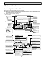
[5] Refrigerant circuit diagram (Representative pattern)
PUHZ-HRP • V/YHA2 + Plate HEX (ACH50) + FTC (TH1/2)
P-sensor
Heat exchanger
Thermistor TH1
(Outlet water)
Refrigerant
GAS pipe
connection
(5/8 inch)
Thermistor
TH6
(Outdoor
2-phase pipe)
Solenoid valve
(Four-way valve)
Ball valve
Strainer
#50
Charge plug
(High pressure)
Charge plug
(Low pressure)
Muffler
Water OUT
Low pressure
switch 63L
Plate HEX
Thermistor TH3
(Outdoor pipe)
High pressure
switch 63H
Thermistor
TH32
(Outdoor pipe)
Strainer
#100
Strainer
#100
Thermistor TH2
(Liquid pipe)
Strainer
#100
Stop valve
(with service port)
Thermistor TH33
(Outdoor pipe)
Strainer
#100
Compressor
Linear
expansion valve C
Bypass
valve
Linear expansion valve A
Strainer
#100
Power
receiver
Refrigerant
LIQUID pipe
connection
(3/8 inch)
Distributor
Thermistor TH4
(Discharge)
Linear
expansion valve B
Water IN
Thermistor TH7
(Outdoor)
Injection port
Heat interchange circuit
Replace
filter
Restrictor
Strainer
valve
#100
Refrigerant flow in cooling
Refrigerant flow in heating
12
[6] Notification to design/select HEX (Refrigerant - Water) Warranty for SPILIT solution
• Specifications of AHU and compatibility with regulations must be confirmed by your company.
• Selection of an apporopriate AHU (with appropriate specifications to match those of units
connected to the AHU such as configuration, dimension, life-span, vibration, noise level,
or features) must be made by your company.
• Mitsubishi Electric shall not be liable for any damage to the entire system or the AHU main
body caused by connected AHU with wrong specification or wrong usage of AHU.
• Mitsubishi Electric shall not be liable for any damage to the outdoor units caused by AHU damage.
( AHU : hydro box or refrigerant - water HEX )
Heat exchanger
(1) Withstanding pressure
Designed pressure of outdoor unit is 4.15 MPa. Following must be satisfied for burst pressure of connecting application.
Burst pressure : More than 12.45 MPa (3 times more than designed pressure)
(2) Performance
Secure the heat exchanger capacity which meets the following conditions. If the conditions are not met, it may result in
malfunction caused by the protection operation or the outdoor unit may be turned off due to the operation of protection
system.
1. Evaporate temperature is more than 4: in max. frequency operation under *1 the cooling rated conditions.
2. In case of hot water supply, condense temperature is less than 58: in max. frequency operation with the outside temperature 7:D.B./6:W.B.
*1. Outdoor: 35:D.B./24:W.B.
(3) Heat exchanger internal capacity
Heat exchanger internal capacity must be within the capacity range shown below. If the heat exchanger below the minimum capacity is connected, it may result in the back flow of liquid or the failure of the compressor.
If the heat exchanger above the maximum capacity is connected, it may result in the deficiency in performance due to lack
of refrigerant or overheating of the compressor.
Minimum capacity : 10 х Model capacity [J] / Maximum capacity : 30 х Model capacity [J]
e.g. When connecting to PUHZ-HRP100 VHA2
Minimum capacity : 10 х 100 =1000 J
Maximum capacity : 30 х 100 =3000 J
Model capacity
60(2.5HP)
71(3HP)
100(4HP)
125(5HP)
140(6HP)
Maximum capacity [J]
1800
2130
3000
3750
4200
Minimum capacity [J]
600
710
1000
1250
1400
(4) Contamination maintenance
1. Wash the inside of heat exchanger to keep it clean. Be sure to rince not to leave flux. Do not use chlorine detergent for
wash.
2. Be sure that the amount of contamination per unit cubic content of heat transfer pipe is less than the following amount.
Example) In case of [ 9.52mm
Residual water : 0.6M/C, Residual oil : 0.5M/C, Solid foreign object : 1.8M/C
Note:
• Install the hydraulic filter at the water intake.
• Use the inlet water of higher than 5 ˚C and lower than 55 ˚C.
• The water in a system should be clean and with pH value of 6.5-8.0.
• The followings are the maximum values;
Calcium : 100mg/L
Chlorine : 100mg/L
Iron/manganese : 0.5mg/L
• Refrigerant pipe diameter from outdoor unit to refrigerant-water HEX (Only for SPLIT type)
Use the pipe with same diameter size as the refrigerant pipe connection diameter of outdoor unit.(Refer to outdoor
unit installation manual.)
• Make sure to perform the frozen prevention measure for water pipe system.(Water piping insulation, back-up pump
system, using of a certain % ethylene glycol instead of normal water)
[Reference]
TB142 has for “Forced Comp. OFF” function as the EXTERNAL INPUT(Contact signal).
To input the abnormal signal of water pump or the abnormal lowering of water flow amount with non-voltage contact
signal makes the outdoor unit stop forcibly. For details, refer to each part of I/F or FTC on this manual.
13
• The water velocity in pipes should be kept within certain limits of material to avoid erosion,corrosion and excessive
noise generation.
Be aware, and take care of , that local velocities in small pipes, bends and similar obstructions can exceed the values
of previous page.
e.g.) Copper : 1.5m/s
Warning
• Use clean enough water which meets water quality standards. The deterioration of water quality may result in the system breakdown or the water leakage.
• Never use anything other than water as a medium. It may cause a fire or an explosion.
• Do not use heated or cooled water that is produced by the air to water heat pump directly for drinking or cooking.
There is a risk to damage your health. There is also a risk that installing the water heat exchanger may corrode if the
necessary water quality for air to water heat pump system cannot be maintained. If you wish to use the heated or
cooled water from the heated pump for these purposes, take measure such as to the second heat exchanger within
the water piping system.
Reference data
Required specification and performance of Plate Heat Exchanger.
Required specification
Refrigerant side
Water side
Burst pressure
Frozen performance
Heat cycle
Endurance pressure
Refrigerant type
R410A
Normal (designed) pressure
4.15MPa
Operating temperature
-20~100:
Refrigerant type
Clean water
Normal (designed) pressure
1.5MPa
Operating temperature
-20~90: (No freezing)
12.45MPa (4.15MPa ×3) or more
Satisfy an initial performance since 5 times or more of deep freezing.
70,000 times or more…Temperature difference: about 50K
72,000 times or more…Pressure difference: 3.3MPa (0 ↔ 3.3MPa)
Required performance
< For 2.5~3 HP >
Required performance of Plate Heat Exchanger
Inlet temperature
Refrigerant side Condensing temperature
(R410A)
Subcool
Max. pressure loss
Inlet temperature
Outlet temperature
Water side
Water flow volume
Max. pressure loss
kW
degC
degC
degC
kPa
degC
degC
L/min
kPa
9.0
75
39.5
2
50
30
35
25.8
50
9.0
100
63.5
2
50
55
60
25.8
50
Gas pipe: [12.7mm
Liquid pipe: [9.52mm
Inlet / outlet pipe: [28.6mm
* For heating mode, used at counter flow direction between refrigerant flow and water one.
< For 4~6 HP >
Required performance of Plate Heat Exchanger
Inlet temperature
Refrigerant side Condensing temperature
(R410A)
Subcool
Max. pressure loss
Inlet temperature
Outlet temperature
Water side
Water flow volume
Max. pressure loss
kW
degC
degC
degC
kPa
degC
degC
L/min
kPa
14.0
75
39.5
2
50
30
35
40.1
50
14.0
100
63.5
2
50
55
60
40.1
50
Gas pipe: [15.88mm
Liquid pipe: [9.52mm
Inlet / outlet pipe: over [28.6mm
* For heating mode, used at counter flow direction between refrigerant flow and water one.
14
3
System design
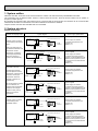
3-1. System type
* with step I/F
* with FTC
Application
by digital/analog signals
simple/basic/analog temp.
Capacity control
For
Manufacturer
Individual installer
Manufacturer
Individual installer
Manufacturer
Individual installer
Manufacturer
Individual installer
Local controller
Air to Air
I/F
Local controller
Air to Water
FTC
Model name
PAC-IF010-E *
PAC-IF011B-E
PAC-IF010-E *
PAC-IF011B-E
PAC-IF010-E *
PAC-IF011B-E
PAC-IF020-E *
PAC-IF021B-E
Type
PCB only
Cased
PCB only
Cased
PCB only
Cased
PCB only
Cased with R/C
STEP I/F
FTC
* PAC-IF010-E, PAC-IF020-E : PCB 10pcs/set
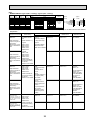
3-2. Combination of remote controller
Remote controller model
Connected object
PAR-21MAA
(Standard)
PAR-W21MAA
(Only for FTC)
PAR-20MAA
(Old )
(Standard)
I/F
FTC
I/F
FTC
I/F
FTC
Connectability
OK
NG (Continue to indicate “PLEASE WAIT”)
NG (Continue to indicate “PLEASE WAIT”)
OK
NG (Continue to indicate “PLEASE WAIT”)
NG (Continue to indicate “PLEASE WAIT”)
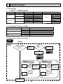
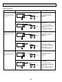
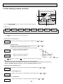
3-3. Flow chart to check system type
ATW
application
start
IF
Variable capacity
request signals for
Heat Pump is
calculated...
capacity
signals
protocol is...
By local
controller
(your side)
Analog
(0-10v/4-20mA…)
Your system is
ANALOG STEP
SYSTEM
(IF)
digital step
(non-voltage contact)
Your system is
DIGITAL STEP
SYSTEM
(IF)
ANALOG STEP
SYSTEM
DIGITAL STEP
SYSTEM
By Non-voltage
Contact signals
By Non-voltage
Contact signals
IF PCB
ON/OF
System controller
(locally supplied)
Operation
mode
-Heating
-Cooling
Capacity
steps
Remote
By Non-voltage
Contact signals
for maintenance
- to check error code
IF PCB
ON/OF
Operation
mode
-Heating
-Cooling
End user interface
Remote
System
controller
(locally supplied)
End user interface
Capacity
steps
By Analog signal
4-20mA / 1-5V / 0-10V
For maintenance purpose
- analog signal parameters
By our FTC
15
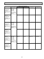
Continued to next page.
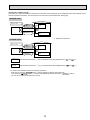
By our FTC
FTC
Heat Pump switch ON/OFF
and the operation mode
change is done…
By remote controller
Your system is
SIMPLE SYSTEM.
(FTC)
By remote controller
Your system is
BASIC SYSTEM.
(FTC)
By external signals from local controller
(non-voltage contact signals)
‘Target flow temperature’ is set…
By external signals from local controller
(Analog signal:4-20mA/ 1-5V/ 0-10V)
Your system is ANALOG TEMP. SYSTEM.
(FTC)
SIMPLE SYSTEM
BASIC SYSTEM
ANALOG TEMP. SYSTEM
By Non-voltage
Contact signals
FTC PCB BOX
FTC PCB BOX
ON/OFF
Operation mode
- Heating
- Heating ECO
- Hot water
- Anti freeze
- Cooling
ON/OFF
By Non-voltage
Contact signals
System controller
(locally supplied)
FTC PCB BOX
ON/OFF
Operation mode
- Heating +
- Cooling
End user interface
System controller
(locally supplied)
End user interface
Target flow temp.
Analog signal
4-20mA/1-5V/0-10V
Operation mode
Target flow temp.
Target flow temp.
Remote controller
Remote controller
Remote controller
End user interface
To preset
- target temp. for each mode
- target temp. parameters
To preset
- analog signal parameters
16
+In this system,
• Heating ECO mode of FTC is
not available.
• It is NOT necessary to switch
operation mode to realize
Hot water mode, Anti freeze
mode and Heating ECO mode.
Simply change the target temp.
by Analog signal.
ATA
application
start
IF
Variable capacity
request signals for
Heat Pump is
calculated...
By local
controller
(your side)
capacity
signals
protocol is...
Analog
(0-10v/4-20mA…)
digital step
(non-voltage contact)
Your system is
ANALOG STEP
SYSTEM
(IF)
Your system is
DIGITAL STEP
SYSTEM
(IF)
By our IF
Your system is
AUTO STEP
SYSTEM
(IF)
AUTO STEP SYSTEM
DIGITAL STEP SYSTEM
ANALOG STEP SYSTEM
By Non-voltage
Contact signals
By Non-voltage
Contact signals
IF PCB
IF
PCB
ON/OF
Operation
mode
-Heating
-Cooling
ON/OFF
Operation mode
Target retern air temp.
Remote controller
End user interface
Remote
controller
for
maintenance
- to check
error code
Capacity
steps
By Non-voltage
Contact signals
17
System
controller
(locally
suppliied)
IF
PCB
ON/OF
Operation
mode
-Heating
-Cooling
End user
interface
Remote
controller
For
maintenance
purpose
- analog signal
System
controller
(locally
suppliied)
End user
interface
Capacity
steps
By Analog
signal
4-20mA / 1-5V / 0-10V
(
Wired Remote Controller
(For Maintenance)
18
TB141
1-2
3-4
5-6
7-8
9-10
11-12
13-14
TB142
10-12
(COM-IN6)
OFF
OFF
ON
ON
OFF
OFF
ON
ON
OFF
TB142
10-11
(COM-IN5)
OFF
ON
OFF
ON
OFF
ON
OFF
ON
OFF
table 3
OFF
ON
ON
ON
ON
OFF
OFF
OFF
OFF
TB142
10-13
(COM-IN7)
Forced Comp. OFF
Fixed operation mode
U
ON
OFF
OFF
OFF
OFF
OFF
OFF
OFF
OFF
U
DSA
SW3
TB6
TB6
0%
{
TB142
Step1
Step4
Step7
AUTO
Auto
Step7
Step4
Step1
OFF
10
11
12
13
14
[ON]
[OFF]
At site
100%
80%
70%
50%
30%
20%
10%
TypeB
SW2-1, SW2-2: ON is valid.
Remark
(Comp. ON)
(Defrosting)
(Cooling)
(Heating)
ON
S1 S2 S3
L N
I/F
Auto
Step7
Step6
Step5
Step4
Step3
Step2
Step1
OFF
S1 S2 S3
L N
At site
[ON]
[OFF]
TypeA
FUSE
ZNR01
CNS2
(RED) 1 2
*2 Remove the
short-circuited connector
CNS2.
ON
Error
ON
ON
ON
ON
TB141
Step for capacity setting
Forced Comp. OFF
Heating
ON
4bit8 switch
OFF~AUTO
TB142
10-14
(COM-IN8)
Normal
Cooling
OFF
OFF
Normal
OFF(Comp. OFF)
OFF
OFF
OFF
OFF
1 2 3 4 5 6 7 8 9 10 11 12 13 14
X1 X2 X3 X4 X5 X6
Operation Output
Error Output
Comp. Output
Defrost Output
Mode(Cool)
Output
Mode(Heat)
Output
Item
1-2 (IN1)
3-4 (IN2)
X1
X2
X3
X4
X5
X6
8
1
ZNR02
Refer to table 1.
(External Output)
TB141
DC311~
339V
LED1
RECTIFICATION
2 4 6 8 10 12 14
1 3 5 7 9 11 13
(External Input)
8
1
SW2
OFF/ON OFF/ON OFF/ON
8
1
SW1
TB142
Item
(OUT1)
(OUT2)
(OUT3)
(OUT4)
(OUT5)
(OUT6)
(OUT7)
LED4
SW6
OFF/ON
1
2
LED2
LED3 LED5
2 4 6 8 10 12 14
1 3 5 7 9 11 13
TB142
table 2
TB142
TB61
1 TB62
2
3 +
4
5
6
1 2 3 4 5 6 7 8 9 10 11 12 13 14
table 1
At site
I/F
(
4-20mA/1-5V/0-10V
Refer to table 2, 3.
(
t°
TH5
Adjustable resistor
t°
TH2
1
2
3
4
5
6
POWER SUPPLY
~/N
0%
OFF
Auto mode
Fixed capacity
(Hz fixed)
mode
TB142
10
11
12
13
14
I/F
100%
50%
10%
Remark
TO OUTDOOR UNIT
*1(Fig.1)
TO OUTDOOR UNIT
{
t°
{
TH1
{
Interface controller
NAME
OFF
OFF
ON
ON
ON
OFF
OFF
OFF
OFF
OFF
OFF
OFF
OFF
ON
OFF
OFF
OFF
OFF
OFF
ON
ON
OFF
OFF
Input
TypeA(4bit-8 setting)
TypeB(1bit-1 setting)
4-20mA
1-5V
0-10V
0-10kΩ
No input(Auto mode)
OFF
OFF
ON
ON
OFF
ON
OFF
ON
Details
[Cooling]FIX
[Heating]FIX
External input(Depending on TB142-3,4)
Not FIX (Depending on Remote controller setting)
Step for capacity setting
OFF/Step 1/Step 2/.../Step 7/Auto
OFF/Step 1/Step 4/Step 7/Auto
OFF/Step 1/Step 2/.../Step 7
OFF/Step 1/Step 2/.../Step 7
OFF/Step 1/Step 2/.../Step 7
OFF/Step 1/Step 2/.../Step 7/Auto
Only Auto mode
OFF
ON
ON
OFF
ON
ON
ON
ON
OFF
OFF
OFF
OFF
SW2-5
Cooling 30 ˚C / Heating 28 ˚C FIX
28 ˚C FIX
26 ˚C FIX
24 ˚C FIX
22 ˚C FIX
20 ˚C FIX
Cooling 19 ˚C/Heating 17 ˚C FIX
Not fixed (Remote controller setting)
Details
Not connect TH5 (Initial setting)
Connect TH5
OFF
ON
Details
SW2-6
table 7 SW2-6 : setting TH5
ON
OFF
OFF
ON
ON
ON
OFF
OFF
SW2-4
ON
OFF
ON
OFF
SW2-3
table 6 SW2-3/2-4/2-5 : Fixed set temperature [For Auto mode]
SW2-2
SW2-1
table 5 SW2-1/2-2 : Fixed operation mode
ON
ON
ON
OFF
ON
ON
OFF
OFF
ON
ON
OFF
OFF
SW1-1 SW1-2 SW1-3 SW6-1 SW6-2
table 4 SW1, SW6 : Input selection of inverter capacity setting
INTERFACE CONTROLLER
TB6
TERMINAL BLOCK(INTERFACE/OUTDOOR CONNECTING LINE)
TB141
TERMINAL BLOCK (External Output)
TB142
TERMINAL BLOCK (External Input REMOTE SWITCH)
TB62
TERMINAL BLOCK (External Input)
TB61
THERMISTOR(TARGET, PIPE)
LED1
POWER SUPPLY(I/F)
LED2~5
OPERATION INDICATION
FUSE
FUSE(T3.15AL250V)
SW1
SWITCH(Input selection of inverter capacity setting) *See table 4.
SW2
SWITCH(Function switch)*See table 5 and 6.
SW3
SWITCH(LED2~5 Display setting)
SW6
SWITCH(4-20mA/1-5V/0-10V switch)*See table 4.
ZNR01,02
VARISTOR
DSA
SURGE ABSORBER
RELAY
X1~X6
TARGET TEMP. THERMISTOR
TH1
(0/15kΩ, 25/5.2kΩ DETECT)
PIPE TEMP. THERMISTOR/LIQUID
TH2
(0/15kΩ, 25/5.2kΩ DETECT)
PIPE TEMP. THERMISTOR/2-PHASE
TH5
(0/15kΩ, 25/5.2kΩ DETECT)
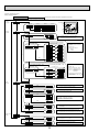
SYMBOL
1. SymboIs used in wiring diagram are,
: Connector,
: Terminal block.
2. Interface controller and outdoor connecting wires have poIarities, make sure to match
terminal numbers(S1, S2, S3) for correct wirings.
3. Since the outdoor side electric wiring may change, be sure to check the outdoor unit
electric wiring diagram for servicing.
4. This diagram shows the wiring of Interface controller and outdoor connecting wires.(specification of 230V),
adopting superimposed system of power and signal.
*1 : When work to supply power separately to Interface controller and outdoor units was applied, refer to Fig 1.
*2 : Remove the short-circuited connector CNS2 when work to supply power separately to
Interface controller and outdoor units was applied.
3-4. Wiring diagram
(1) PAC-IF011B-E(I/F)
。
TB142
1
2
3
4
5
6
7
8
9
10
11
12
13
14
FTC
TB61
8
LED1
At site
8
1
SW3
U
1 2 3 4 5 6 7 8 9 10 11121314
X1 X2 X3 X4 X5 X6 X7
ZNR01
DSA
TB141
TB6
S1 S2 S3
L N
TB6
*2 Remove the
short-circuited
connector CNS2.
S1 S2 S3
L N
CNS2
(RED) 1 2
ZNR02 FUSE
U
Refer to Table 2.
2 4 6 8 10 12 14
1 3 5 7 9 11 13
DC311∼
339V
(External Output)
FTC
8
RECTIFICATION
2 4 6 8 10 12 14
1 3 5 7 9 11 13
Refer to
Table 1.
SW2
1
OFF/ON OFF/ON OFF/ON
SW1
(External Input)
OFF/ON
SW6
1
TB141
1
2
LED2 LED4
LED3 LED5
TB142
1 TB62
2
3 +
4
5
6
1
2
3
4
5
6
19
NAME
SYMBOL
FLOW TEMP. CONTROLLER(FTC)
TB6
TERMINAL BLOCK(FTC/OUTDOOR UNIT CONNECTING LINE)
TB141
TERMINAL BLOCK (External Output)
TB142
TERMINAL BLOCK (External Input Contact signal)
TB62
TERMINAL BLOCK (External Input Analog signal)
TB61
TERMINAL BLOCK (Thermistor)
LED1
POWER SUPPLY(FTC)
LED2
POWER SUPPLY(WIRED REMOTE CONTROLLER)
LED3
TRANSMISSION(FTC-OUTDOOR UNIT)
LED4, 5
NOT IN USE
FUSE
FUSE(T3.15AL250V)
SW1
SWITCH *See Table 3, 4 and 6.
SW2
SWITCH
SW3
SWITCH *See Table 5.
SW6
SWITCH(4-20mA/1-5V/0-10V switch) *See Table 3.
ZNR01,02
VARISTOR
DSA
SURGE ABSORBER
X1∼X7
RELAY
ACTUAL FLOW WATER TEMP. THERMISTOR (Water piping)
TH1
(0℃/15kΩ, 25℃/5.2kΩ DETECT)
PIPE TEMP. THERMISTOR/LIQUID (Refrigerant piping)
TH2
(0℃/15kΩ, 25℃/5.2kΩ DETECT)
TO OUTDOOR UNIT
POWER SUPPLY
∼/N
TO OUTDOOR UNIT
*1(Fig.1)
1. SymboIs used in wiring diagram are,
: Connector, : Terminal block.
2. FTC and outdoor unit connecting wires have poIarities, make sure to match terminal numbers(S1,
S2, S3) for correct wirings.
3. Since the outdoor unit side electric wiring may change, be sure to check the outdoor unit electric
wiring diagram for servicing.
4. This diagram shows the wiring of FTC and outdoor unit connecting wires (specification of 230V),
adopting superimposed system of power and signal.
*1 : When work to supply power separately to FTC and outdoor unit was applied, refer to Fig 1.
*2 : Remove the short-circuited connector CNS2 when work to supply power separately to FTC
and outdoor unit was applied.
Heating →
HeatingECO →
Hot Water →
Anti-Freeze →
Cooling →
Forced Comp. OFF →
At site
(
Wired Remote Controller
t
(
TH2
4-20mA/1-5V/0-10V
*6
。
t
{
{
TH1
{
FLOW TEMP. CONTROLLER (FTC)
(IN4)
(COM-IN5)
(COM-IN6)
(COM-IN7)
(COM-IN8)
7-8
10-11
10-12
10-13
10-14
(OUT7)
13-14
X7
X1
X2
X3
X4
X5
X6
Outdoor unit *6
SPLIT type
PACKAGED type
SPLIT type
PACKAGED type
4-20mA
SPLIT type
PACKAGED type
1-5V
SPLIT type
PACKAGED type
0-10V
SPLIT type
PACKAGED type
DIP switch on PCB
SPLIT type
SW2-1∼8, SW3-1∼3 PACKAGED type
Wired remote controller SPLIT type
PACKAGED type
Wired remote controller SPLIT type
PACKAGED type
Change TEMP. Input
DIP switch on PCB
SW2-1∼8, SW3-1∼3
Wired remote controller
SW1-1
ON
ON
ON
ON
OFF
OFF
OFF
OFF
ON
ON
OFF
OFF
OFF
OFF
OFF
OFF
̶
OFF
OFF
Normal
OFF
OFF
OFF
OFF
SW1-2
OFF
OFF
OFF
OFF
ON
ON
ON
ON
ON
ON
OFF
OFF
OFF
OFF
OFF
OFF
SW1-5
OFF
ON
OFF
ON
OFF
ON
OFF
ON
OFF
ON
OFF
ON
OFF
ON
OFF
ON
̶
ON
ON
Error
ON
ON
ON
ON
Remark
Not in use
Not in use
SW3-6=OFF
SW3-6=ON
SW1-6
ON
ON
OFF
OFF
OFF
OFF
OFF
OFF
OFF
OFF
ON
ON
OFF
OFF
OFF
OFF
Operation mode
Heating/Heating ECO/Hot water/Anti-freeze/Cooling
Heating/Heating ECO/Hot water/Anti-freeze
Item
Normal
Forced Comp. OFF
Forced Comp. OFF
Normal
*7. Don’
t use this setting when using the SPLIT type outdoor unit.
*8. Refer to installation manual.
SW6-2
OFF
OFF
OFF
OFF
ON
ON
ON
ON
OFF
OFF
OFF
OFF
OFF
OFF
OFF
OFF
BH79L347H01
SW1-6=OFF
Set temperature range with wired remote controller
SW1-6=ON
Set temperature table with DIP switch of FTC
SW1-6 SW1-7 SW1-8 Temperature range with wired remote controller
Cooling
Heating/HeatingECO/Hot Water Anti-Freeze
OFF
OFF
OFF
Upper 45 ℃ / lower 5 ℃ Upper 25 ℃ / lower 5 ℃
Upper 55 ℃ / lower 20 ℃
OFF
ON
OFF
Upper 45 ℃ / lower 5 ℃ Upper 25 ℃ / lower 5 ℃
Upper 60 ℃ / lower 20 ℃ *7
OFF
OFF
ON
Upper 45 ℃ / lower 5 ℃ Upper 25 ℃ / lower 5 ℃
Upper 50 ℃ / lower 20 ℃
OFF
ON
ON
̶
̶
̶
ON
OFF
OFF
̶
̶
̶
ON
ON
OFF
̶
̶
̶
ON
OFF
ON
̶
̶
̶
ON
ON
ON
̶
̶
̶
Set temperature range
TB142 No.5-6 input
OFF(open)
ON(short)
OFF(open)
ON(short)
Table 6 SW1-6,7,8
ON
OFF
SW3-6
Table 5 SW3-6 Logic of Forced comp. OFF external signal (TB142 5-6)
SW1-3
OFF
ON
SW6-1
OFF
OFF
OFF
OFF
ON
ON
OFF
OFF
OFF
OFF
OFF
OFF
OFF
OFF
OFF
OFF
Temperature table
SW2-1∼8, SW3-1∼3
̶
̶
̶
̶
Table
*8
Table*8
̶
̶
0∼2mA : STOP
0∼0.5V : STOP
The signal of external input is prior to the signal of wired remote controller.
SPLIT type : the standard outdoor unit without a plate HEX(refrigerant-water HEX) inside.
PACKAGED type : the Air to water outdoor unit with a plate HEX(refrigerant-water HEX) inside.
(It is not necessary to connect to TH2.)
Change mode Input
External input
(non-voltage contact)
External input
(non-voltage contact)
External input
(non-voltage contact)
External input
(non-voltage contact)
External input
(non-voltage contact)
External input and
Wired remote controller
External input and
Wired remote controller
Wired remote controller
Table 4 SW1-3 Prohibition of Cooling mode
*3.
*4.
*5.
*6.
External input and *5
Wired remote controller
External input and *5
Wired remote controller
Wired remote controller
ON/OFF Input
External input
(non-voltage contact)
External input
(non-voltage contact)
External input or
4-20mA *3
External input or
1-5V *4
External input
ON
̶
̶
Forced Comp. OFF
Normal
Cooling
Heating
Heating ECO
Hot Water
Anti-Freeze
Item
Operation Output
Error Output
Comp. Output
Defrost Output
Mode(Cooling) Output
Mode(Heating/HeatingECO/
Hot Water/ Anti-Freeze) Output
̶
OFF
̶
̶
Normal
Forced Comp. OFF
OFF
OFF
OFF
OFF
OFF
Table 3 SW1,SW6 : Input selection
(OUT1)
(OUT2)
(OUT3)
(OUT4)
(OUT5)
(OUT6)
TB141
1-2
3-4
5-6
7-8
9-10
11-12
Table 2 External output
(IN1)
(IN2)
(IN3)
1-2
3-4
5-6
TB142
Table 1 External input(Contact signal)
(2) PAC-IF021B-E(FTC)
3-5. PCB diagram(Test point )
(1) PAC-IF011B-E, PAC-IF010-E
CN20
Thermistor (TH1)
LED2~5
LED1
Power supply
TB61 1-2
Thermistor (TH1)
TB61 3-4
Thermistor (TH2)
CN21
Thermistor (TH2)
TB61 5-6
Thermistor (TH5)
CN29
Thermistor (TH5)
CN2P
Adjustable resistor
TB62 1-2
Adjustable resistor
CN2A
4-20mA/1-5V/0-10V
TB62 3-4
4-20mA/1-5V/0-10V
CN22
Wired remote
controller
TB62 5-6
Wired remote
controller
CN82
External input
Remote switch
TB142
External input
Remote switch
CNX2
CNX4
CNX6
CN53
Error Output
Defrost Output
Mode(Heat)Output
External input
Remote switch
CNX1
CNX3
CNX5
Operation Output Comp.Output
Mode(Cool)Output
TB141
External output
TB6
TB141
TB142
TB61
TB62
CNX1~CNX6
CN20
CN21
CN29
CN2P
CN2A
CN22
PAC-IF011B-E
PAC-IF010-E
Ο
Ο
Ο
Ο
Ο
Ο
—
Ο
Ο
Ο
Ο
Ο
Ο
—
Ο
Ο
Ο
Ο
Ο
Ο
Ο
Ο
Ο
Ο
Ο : mounting
— : unmounting
20
FUSE
T3,15AL250V
TB6
Interface/outdoor
connecting
(2) PAC-IF021B-E(FTC), PAC-IF020-E
CN20
Thermistor (TH1)
TB6
FTC/outdoor unit
connecting
LED2,3
TB61 1-2
Thermistor (TH1)
TB61 3-4
Thermistor (TH2)
CN21
Thermistor (TH2)
TB62 3-4
4-20mA/1-5V/0-10V
CN2A
4-20mA/1-5V/0-10V
TB62 5-6
Wired remote
controller
CN22
Wired remote
controller
CN82
External input
CN53
External input
TB142
External input
CNX2
Error Output
CNX1
Operation Output
CNX4
Defrost Output
CNX3
Comp.Output
TB141
External output
TB6
TB141
TB142
TB61
TB62
CNX1~CNX6
CN20
CN21
CN29
CN2P
CN2A
CN22
PAC-IF021B-E
PAC-IF020-E
Ο
Ο
Ο
Ο
Ο
Ο
—
Ο
Ο
Ο
Ο
Ο
Ο
Ο
Ο
Ο
Ο
—
Ο
Ο
Ο
Ο
Ο
Ο
Ο : mounting
— : unmounting
21
CNX6
Mode(Heating/Heating
ECO/Hot Water/Anti-Freeze)Output
CNX5
Mode(Cooling)Output
FUSE
T3,15AL250V
3-6. Specification of connectors
Please connect wiring with either of the terminal bed or the connector.
Parts on the PCB are different depending on the model.
PCB ONLY
PAC-IF010-E
PAC-IF020-E
Parts on PCB
TERMINAL BED
TB6
TB142
TB61
TB62
Cased
PAC-IF011B-E
PAC-IF021B-E
Parts on PCB
TERMINAL BED
TB6
TB141
CONNECTOR
CNX1
CNX2
CNX3
CNX4
CNX5
CNX6
CN82
CN53
CN20
CN21
CN29
CN2P
CN2A
CN22
CONNECTOR
TB142
TB61
TB62
CN20
CN21
CN29
CN2P
CN2A
CN22
The following terminal bed and the connector is the same signals, meaning.
TB6
TERMINAL BED
TB6-L
TB6-N
TB6-PE
TB6-S1
TB6-S2
TB6-S3
TB141, TB142, TB61
CONNECTOR
NAME
—
—
—
—
—
—
PIN No.
—
—
—
—
—
—
Specification of connectors (Manufacture: J.S.T. Mfg. Co., Ltd.)
CONNECTOR NAME
CNX1 ~ 6
CN82
CN53
CN20,21,29,2P,2A,22
HOUSING
VHR-3N
XAP-08V-1
XAP-05V-1
XAP-02V-1
Contact pin : According to the wiring size select the correct
contact pin by yourself.
TERMINAL BED
TB141-1,2
TB141-3,4
TB141-5,6
TB141-7,8
TB141-9,10
TB141-11,12
TB142-1
TB142-2
TB142-3
TB142-4
TB142-5
TB142-6
TB142-7
TB142-8
TB142-9
TB142-10
TB142-11
TB142-12
TB142-13
TB142-14
TB61-1,2
TB61-3,4
TB61-5,6
TB62-1,2
TB62-3,4
TB62-5,6
22
CONNECTOR
NAME
CNX1
CNX2
CNX3
CNX4
CNX5
CNX6
CN82
CN82
CN82
CN82
CN82
CN82
CN82
CN82
CN53
CN53
CN53
CN53
CN53
CN53
CN20
CN21
CN29
CN2P
CN2A
CN22
PIN No.
1,3pin
1,3pin
1,3pin
1,3pin
1,3pin
1,3pin
1pin
2pin
3pin
4pin
5pin
6pin
7pin
8pin
5pin
5pin
1pin
2pin
3pin
4pin
1,2pin
1,2pin
1,2pin
1,2pin
1,2pin
1,2pin
4
Inter face (I / F)
CONTENTS
1.
2.
3.
4.
5.
6.
7.
8.
9.
10.
11.
12.
System outline .................................................................................. 24
System structure ............................................................................... 24
Power supply .................................................................................... 28
Connecting thermistor....................................................................... 30
Interface controller switch setting ..................................................... 31
Input specifications ........................................................................... 32
Output specifications ........................................................................ 33
LED display detail ............................................................................. 34
Maintenance information .................................................................. 35
Central control .................................................................................. 52
Outlines and dimensions .................................................................. 53
Troubleshooting ................................................................................ 54
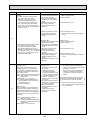
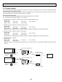
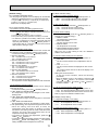
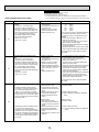
Notes on system controller side in I/F connection system
(1) Please do not transmit “STEP 0” during defrost operation.
Defrost operation might be interrupted, and frost remain.
(Please demand the planned capacity step even when the system controller receives defrost signal from the heat
pump (outdoor unit)).
(2) Please do not transmit “STEP 0” when the outdoor unit(H/P) is abnormal.
Abnormal detection data is reset, and an Abnormal point cannot be confirmed.
23
1. System outline
With PAC-IF011B-E, local units can be connected with the outdoor units manufactured by MITSUBISHI ELECTRIC.
The commands, such as Remote switch, Varistor, 4-20mA/1-5V/0-10V and etc., allow the inverter outdoor unit to operate, to
stop and to switch capacity.
By outputting the operation state, the interface can be connected with the local unit.Also, the interface can be connected with
wired remote controller for maintenance so that the maintenance information is obtained.
Only the outdoor units with self-controlled S/W are connectable.
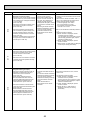
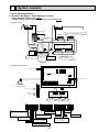
2. System structure
System structure(1)
Outdoor unit capacity switch
System diagram
Power supply specifications
Remote switch
Capacity switch of outdoor
unit according to the remote
switch
When auto stop being set,
the difference between room
temperature and set
temperature of interface,
and the pipe temperature
switch the capacity of
outdoor unit automatically.
Power supplied from outdoor unit
Local unit
Local controller
Intake temp.
Liquid pipe temp.
Local unit
Local controller
Wired remote controller
(Auto step mode only)
The difference between
room temperature and set
temperature of wired remote
controller, and the pipe
temperature switch the
capacity of outdoor unit
automatically.
As with the remote controller
for air conditioner, the
interface performs ON/OFF
operation, and changes
operation mode (cooling,
heating ,fan) and set
temperature.
A transmission line/Power line
Intake temp.
Liquid pipe temp.
Power line
Interface controller
Remote switch
Power line
Outdoor unit
A transmission line/Power line
Power line
Interface controller
Remote switch
Outdoor unit
Separate interface/outdoor unit
power supplies
Power supply for interface
controller and power supply for
outdoor unit are supplied from the
different source.(Common power
source for local unit and interface
controller)
Refer to 3.2.
Power supplied from outdoor unit
A transmission line/Power line
Intake temp.
Liquid pipe temp.
Local unit
Wired
remote controller
Intake temp.
Liquid pipe temp.
Local unit
Wired
remote controller
Power line
Interface controller
PAR-21MAA
Power line
Separate interface/outdoor unit
power supplies
A transmission line/Power line
Power line
Interface controller
PAR-21MAA
Power supply for interface
controller is supplied from the
outdoor unit.
Refer to 3.1.
Outdoor unit
Outdoor unit
Adjustable resistor(0-10kΩ)
Capacity switch of outdoor
unit according to the
adjustable resistor
Power supply for interface
controller is supplied from the
outdoor unit.
Refer to 3.1.
Power supply for interface
controller and power supply for
outdoor unit are supplied from the
different source.(Common power
source for local unit and interface
controller)
Refer to 3.2.
Power supplied from outdoor unit
A transmission line/Power line
Intake temp.
Liquid pipe temp.
Local unit
Local controller
Intake temp.
Liquid pipe temp.
Local unit
Local controller
Power line
Interface controller
Adjustable resistor
Power line
Outdoor unit
Separate interface/outdoor unit
power supplies
A transmission line/Power line
Power line
Interface controller
Adjustable resistor
Power supply for interface
controller is supplied from the
outdoor unit.
Refer to 3.1.
Outdoor unit
24
Power supply for interface
controller and power supply for
outdoor unit are supplied from the
different source.(Common power
source for local unit and interface
controller)
Refer to 3.2.
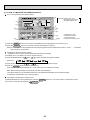
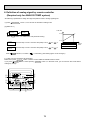
Note:
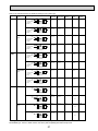
• REMOTE SWITCH Type A (4bit - 8 setting) / Type B (1bit -1 setting)
TB142
TB142
TB142
TB142
10-11
10-12
10-13
10-14
(COM-IN5) (COM-IN6) (COM-IN7) (COM-IN8)
Step for capacity setting *
OFF
ON
OFF
ON
OFF
ON
OFF
ON
OFF
[OFF]
[ON]
OFF
OFF
ON
ON
OFF
OFF
ON
ON
OFF
OFF
OFF
OFF
OFF
ON
ON
ON
ON
OFF
OFF
OFF
OFF
OFF
OFF
OFF
OFF
OFF
ON
TypeA
TypeB
OFF
0%
Step1
10%
Step2
20%
Step3
30%
Step4
50%
Step5
70%
Step6
80%
Step7
100%
Auto step
[OFF]
[ON]
OFF
Step1
Step4
0%
10%
50%
Step7
100%
Remark
Type A
OFF
At site
Fixed capacity
(Hz fixed)
mode
4 bit 8 switch
OFF~AUTO
step
Type B
I/F
{
10
11
12
13
14
At site
Step1
Step4
Step7
AUTO
step
TB142
Auto step
I/F
10
11
12
13
14
TB142
Auto step mode
* The actual capacity will be slightly different from the numerial data in this table depending on conditions such as the ambient
temperature.
Attachment of sensor
Refer to 4.
Pipe-thermistor/
2-phase might be
neccessary
depending on the
type of the outdoor
unit.
Refer to 4.
Pipe-thermistor/
2-phase might be
neccessary
depending on the
type of the outdoor
unit.
Refer to 4.
Pipe-thermistor/
2-phase might be
neccessary
depending on the
type of the outdoor
unit.
Refer to 4.
Pipe-thermistor/
2-phase might be
neccessary
depending on the
type of the outdoor
unit.
Refer to 4.
Pipe-thermistor/
2-phase might be
neccessary depending
on the type of the
outdoor unit.
Refer to 4.
Pipe-thermistor/
2-phase might be
neccessary depending
on the type of the
outdoor unit.
Interface controller
switch setting
Interface controller specifications
Input and wiring
Output and wiring
2 patterns can be
set.
(Refer to NOTE 1.)
Type A
OFF/Step1/Step2/
···Step7/Auto step
Type A
SW1-1:OFF
SW1-2:OFF
SW1-3:OFF
SW6-1:OFF
SW6-2:OFF
Type B
OFF/Step1/Step4/
Step7/Auto step
TB62
Connect the wired
remote
controller wire to
No.5-6
Wiring
Other switches are
Wire NO.×size(mm2)
to be set according
2×0.3(Non-polar)
to the site.
Max. 500m
Refer to 5 for details.
Circuit rating
DC12V
The figure is NOT
always against the
ground.
Refer to 7.
Refer to 8, 9.
Not available
Refer to 7.
Refer to 8, 9.
Not available
Refer to 7.
Refer to 8, 9.
Available
Refer to 10.
Connect adaptor to
outdoor unit.
M-NET converter
PAC-SF80MA-E
A-Control sub
Interface
PAC-SK82SI-E
Refer to 7.
Refer to 8, 9.
Available
Refer to 10.
Connect adaptor to
outdoor unit.
M-NET converter
PAC-SF80MA-E
A-Control sub
Interface
PAC-SK82SI-E
Only the operation
with remote
controller is valid.
(External signal is
invalid)
SW1-1:OFF
SW1-2:OFF
SW1-3:ON
SW6-1:OFF
SW6-2:OFF
Connection with
BMS/MELANS
Refer to 6 for details.
Type B
SW1-1:ON
SW1-2:OFF
SW1-3:OFF
SW6-1:OFF
SW6-2:OFF
Other switches are
to be set according
to the site.
Refer to 5 for details.
SW1-1:OFF
SW1-2:ON
SW1-3:ON
SW6-1:OFF
SW6-2:OFF
Other functions/setting
Maintenance
Refer to 6.
Refer to 7.
Refer to 8, 9.
Not available
Refer to 6.
Other switches are
to be set according
to the site.
Refer to 5 for details.
Refer to 7.
Refer to 8, 9.
Not available
25
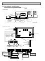
System structure(2)
Outdoor unit capacity switch
System diagram
Power supply specifications
4-20mA
Capacity switch of outdoor
unit according to the signal
of 4-20mA
Power supplied from outdoor unit
A transmission line/Power line
Intake temp.
Liquid pipe temp.
Local unit
Local controller
4-20mA
Local controller
1-5V
Capacity switch of outdoor
unit according to the signal
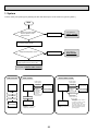
of 1-5V
Outdoor unit
Power line
Intake temp.
Liquid pipe temp.
Local unit
Power line
Interface controller
A transmission line/Power line
Power line
Interface controller
4-20mA
Outdoor unit
Separate interface/outdoor unit
power supplies
Power supply for interface
controller and power supply for
outdoor unit are supplied from the
different source.
(Common power source for local
unit and interface controller)
Refer to 3.2.
Power supplied from outdoor unit
A transmission line/Power line
Intake temp.
Liquid pipe temp.
Local unit
Local controller
Local unit
Local controller
Power line
Interface controller
1-5V
Power supply for interface
controller is supplied from the
outdoor unit.
Refer to 3.1.
Outdoor unit
Power line
Intake temp.
Liquid pipe temp.
A transmission line/Power line
Power line
Interface controller
1-5V
Outdoor unit
0-10V
Capacity switch of outdoor
unit according to the signal
of 0-10V
Power supply for interface
controller is supplied from the
outdoor unit.
Refer to 3.1.
Separate interface/outdoor unit
power supplies
Power supply for interface
controller and power supply for
outdoor unit are supplied from the
different source.
(Common power source for local
unit and interface controller)
Refer to 3.2.
Power supplied from outdoor unit
A transmission line/Power line
Intake temp.
Liquid pipe temp.
Local unit
Local controller
0-10V
Local controller
Outdoor unit
Power line
Intake temp.
Liquid pipe temp.
Local unit
Power line
Interface controller
Separate interface/outdoor unit
power supplies
A transmission line/Power line
Power line
Interface controller
0-10V
Power supply for interface
controller is supplied from the
outdoor unit.
Refer to 3.1.
Outdoor unit
26
Power supply for interface
controller and power supply for
outdoor unit are supplied from the
different source.
(Common power source for local
unit and interface controller)
Refer to 3.2.
Attachment of sensor
Refer to 4.
Pipe-thermistor/
2-phase might be
neccessary
depending on the
type of the outdoor
unit.
Interface controller
switch setting
SW1-1:ON
SW1-2:ON
SW1-3:OFF
SW6-1:ON
SW6-2:ON
Interface controller specifications
Input and wiring
Output and wiring
Other functions/setting
Maintenance
Connection with
BMS/MELANS
Refer to 6.
Refer to 7.
Refer to 8, 9.
Not available
Refer to 6.
Refer to 7.
Refer to 8, 9.
Not available
Refer to 6.
Refer to 7.
Refer to 8, 9.
Not available
Refer to 6.
Refer to 7.
Refer to 8, 9.
Not available
Refer to 6.
Refer to 7.
Refer to 8, 9.
Not available
Refer to 6.
Refer to 7.
Refer to 8, 9.
Not available
Other switches are
to be set according
to the site.
Refer to 5 for details.
Refer to 4.
Pipe-thermistor/
2-phase might be
neccessary
depending on the
type of the outdoor
unit.
Refer to 4.
Pipe-thermistor/
2-phase might be
neccessary
depending on the
type of the outdoor
unit.
SW1-1:ON
SW1-2:ON
SW1-3:OFF
SW6-1:OFF
SW6-2:ON
Other switches are
to be set according
to the site.
Refer to 5 for details.
Refer to 4.
Pipe-thermistor/
2-phase might be
neccessary
depending on the
type of the outdoor
unit.
Refer to 4.
Pipe-thermistor/
2-phase might be
neccessary
depending on the
type of the outdoor
unit.
Refer to 4.
SW1-1:OFF
SW1-2:OFF
SW1-3:ON
SW6-1:OFF
SW6-2:OFF
Other switches are
to be set according
to the site.
Refer to 5 for details.
Pipe-thermistor/
2-phase might be
neccessary
depending on the
type of the outdoor
unit.
27
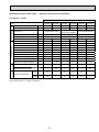
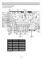
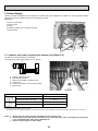
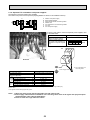
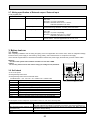
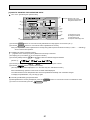
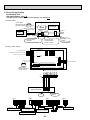
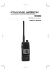
3. Power Supply
Interface controller is applicable to both methods of interface unit power supplied from outdoor unit, and of separate interface
unit/outdoor unit power supplies. Choose one according to the site.
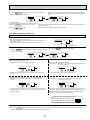
(Photo. 3-1)
A Inlet for control cable
B Inlet for power
C Clamp
D Interface / Outdoor unit connecting terminals
E Earth terminal
D
C
C
Photo.3-1
E
A
B
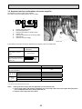
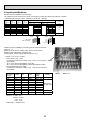
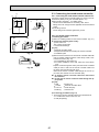
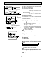
3.1. Interface unit power supplied from outdoor unit (Photo 3-2)
The following connection patterns are available.
The outdoor unit power supply patterns vary on models.
D
A
B
C
F
L
N
S1
S1
S2
S2
S3
S3
E
A
B
C
D
E
F
Outdoor unit power supply
Earth leakage breaker
Wiring circuit breaker or isolating switch
Outdoor unit
Interface unit/outdoor unit connecting cables
Interface unit
Photo.3-2
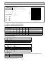
Wiring
Circuit Wire No.×
rating
size
(mm2)
Interface unit model
PAC-IF011B-E
Interface unit-Outdoor unit
*1
3× 1.5 (polar)
Interface unit-Outdoor unit earth
*1
1 × Min.1.5
Interface unit-Outdoor unit S1-S2
*2
AC 230 V
Interface unit-Outdoor unit S2-S3
*2
DC24 V
*1. Max. 80 m
*2. The figures are NOT always against the ground.
S3 terminal has DC 24 V against S2 terminal. However between S3 and S1, these terminals are not electrically insulated by the transformer or other device.
Notes: 1.
2.
3.
Wiring size must comply with the applicable local and national code.
Power supply cables and interface unit/outdoor unit connecting cables shall not be lighter than polychloroprene sheathed flexible cable. (Design 60245 IEC 57)
Install an earth longer than other cables.
28
3.2. Separate interface unit/outdoor unit power supplies
The following connection patterns are available.
The outdoor unit power supply patterns vary on models.
D
A
B
C
L
N
F
G
B
S1
S2
S3
A
B
C
D
E
F
G
L
N
C
S1
S2
S3
E
Outdoor unit power supply
Earth leakage breaker
Wiring circuit breaker or isolating switch
Outdoor unit
Interface unit/outdoor unit connecting cables
Interface unit
Interface unit power supply
Photo. 3-3
CNS2
If the interface and outdoor units have separate power supplies, refer to the table below.
Separate power supply
specifications
Interface unit controller connector (CNS2) connection
change
Outdoor unit DIP switch settings (when using separate interface unit/outdoor unit power
supplies only)
Disconnected
ON
OFF
3
1
2
(SW8)
Set the SW8-3 to ON.
PAC-IF011B-E
~/N (Single Phase), 50 Hz, 230 V
*2
Circuit
rating
*1
Wiring
Wire
No.×
size
(mm2)
Interface unit model
Interface unit power supply
Interface unit input capacity
Main switch (Breaker)
Interface unit power supply & earth
Interface unit-Outdoor unit
Interface unit-Outdoor unit earth
Interface unit L-N
Interface unit-Outdoor unit S1-S2
Interface unit-Outdoor unit S2-S3
*3
*3
*3
16 A
3 × Min. 1.5
2 × Min. 0.3
–
AC230V
–
DC24V
*1. A breaker with at least 3.0mm contact separation in each pole shall be provided. Use earth leakage breaker (NV).
*2. Max. 120 m
*3. The figures are NOT always against the ground.
Notes: 1. Wiring size must comply with the applicable local and national code.
2. Power supply cables and interface unit/outdoor unit connecting cables shall not be lighter than polychloroprene sheathed flexible cable. (Design 60245 IEC 57)
3. Install an earth longer than other cables.
29
4. Connecting thermistor
4.1 Connecting thermistor cable
Connect the thermistor for the interface controller.
When the thermistor cables are too long, cut it to the appropriate length.
Do not bind it in the interface unit.
TB61
TH1
TH2
TH5
1. Target temp. thermistor (TH1)
Connect the thermistor for the target temp. to 1 and 2 on
the terminal block (TB61) on the interface controller.
2. Pipe temp. thermistor / Liquid (TH2)
Connect the thermistor for the pipe temp. to 3 and 4 on
the terminal block (TB61) on the interface controller.
3. Pipe temp. thermistor / 2-phase (TH5).
Connect the thermistor for the 2-phase temp. to 5 and 6
on the terminal block (TB61) on the interface controller.
Set the DIP switch 2-6 to OFF of the interface controller.
Photo. 4-1
Caution:
Do not route the thermistor cables together with power cables.
The sensor part of the thermistor should be installed where user must not touch.
(It is separated by the supplementary insulation from where user may touch.)
4.2 Thermistor position
< Target temp. thermistor (TH1) > (Used only in *auto step mode (Only for Air to Air applications))
1. Put thermistor(TH1) where average intake temperature for heat exchanger can be detected.
2. It is better to put thermistor(TH1) where radiant heat from heat exchanger can be avoided.
To use this interface for manual step control, put a fixed resistor of 4~10kΩ instead of thermistor.(TH1 on the terminal block
TB61)
* Auto step mode: In this mode, the capacity step of the outdoor unit is controlled automatically to let the target (intake)
temperature reach the set temperature.(Only for air to air application)
< Liquid pipe thermistor (TH2) >
1. Put thermistor(TH2) where liquid refrigerant pipe temperature can be detected.
2. It is better to protect the thermistor(TH2) with heat insulating materials not to be affected by the ambient temperature, etc.
3. In case that the refrigerant is distributed by distributor, put thermistor(TH2) before the distributor.
< 2 phase pipe (condensing/evaporating) thermistor (TH5) >
*Only for Air to Air application (Refer to page.4)
*Only in AUTO STEP mode of the I/F (Refer to page.4)
1. 2 phase pipe thermistor must be located where the 2 phase (condensing / evaporating) temperature of HEX can be measured.
2. Preferably, it should be insulated to avoid any influences by the ambient air temperature and so.
3. It must be located where it does NOT measure hot gas/subcool liquid temperature in heating mode.
4. If HEX is divided into several paths, 2 phase pipe thermistor should be put on the upper path.(Liquid refrigerant tends to stay
in the lower path when HEX works as a condenser, and the improper temperature may possibly be picked up.)
5. 2 phase thermistor should be located in the middle of the path. If it is impossible to put it in the middle, it should be put a bit
inlet side of condenser. Do NOT move it too much to the inlet side, however, as it may possibly pick up hot gas temperature.
(Never put it on the outlet side of condenser as it may pick up subcool liquid temperature.)
30
< Thermistor for lower temperature >
<Thermistor Characteristic graph>
50
Target temperature thermistor (TH1)
Thermistor for
lower temperature Pipe temperature thermistor/liquid (TH2)
Pipe temperature thermistor / 2-phase (TH5)
Resistance (k)
Thermistor R0 =15k" ± 3%
Fixed number of B =3480 ± 2%
Rt =15exp { 3480 (
0:
10:
20:
25:
30:
40:
40
1 – 1 )}
273+t
273
15k"
9.6k"
6.3k"
5.4k"
4.3k'
3.0k"
30
20
10
0
-20 -10 0
10 20 30 40 50
Temperature ()
5. Interface controller switch setting
Set the switches following the system specifications below.
Switch1. Switch6 : Input selection of inverter capacity setting
Input
REMOTE SWITCH
Type A (4bit-8 setting)
REMOTE SWITCH
Type B (1bit-1 setting)
4-20mA
1-5V
0-10V
0-10kΩ
No input (AUTO mode)
SW 1-1
SW 1-2
SW 1-3
SW 6-1
SW 6-2
Step for capacity setting
OFF
OFF
OFF
OFF
OFF
OFF/Step1/Step2/…/Step7/Auto step
ON
OFF
OFF
OFF
OFF
OFF/Step1/Step4/Step7/Auto step
ON
ON
OFF
ON
OFF
ON
ON
OFF
OFF
ON
OFF
OFF
ON
ON
ON
ON
OFF
OFF
OFF
OFF
ON
ON
OFF
OFF
OFF
OFF/Step1/Step2/…/Step7
OFF/Step1/Step2/…/Step7
OFF/Step1/Step2/…/Step7
OFF/Step1/Step2/…/Step7/Auto step
Only Auto step mode
SW1-4~8 : OFF fixed (Initial setting)
• SW2-1/2-2 : Fixed operation mode
SW2-1
OFF
ON
OFF
ON
SW2-2
OFF
OFF
ON
ON
Details
Not FIX (Depending on Remote controller setting)
[Cooling]FIX
[Heating]FIX
External input(Depending on TB142-3,4)
• SW2-3/2-4/2-5 : Fixed set temperature [For Auto step mode only]
SW2-3
OFF
ON
OFF
ON
OFF
ON
OFF
ON
SW2-4
OFF
OFF
ON
ON
OFF
OFF
ON
ON
SW2-5
OFF
OFF
OFF
OFF
ON
ON
ON
ON
Details
Not fixed (Remote controller setting)
Cooling 19 ˚C /Heating 17 ˚C FIX
20 ˚C FIX
22 ˚C FIX
24 ˚C FIX
26 ˚C FIX
28 ˚C FIX
Cooling 30 ˚C / Heating 28 ˚C FIX
Set switches in case of auto step mode.
SW2-6 : Setting of TH5
When TH5 (2-phase pipe temp. thermistor) is connected, it is necessary to set the Dip SW2-6 of the interface controller.
SW2-6
OFF
ON
Details
Connect TH5
Not connect TH5 (Initial setting)
SW2-7, 8 : OFF fixed (Initial setting)
SW3 : LED2~5 display setting (Refer to 8.)
31
6. Input specifications
Demand control is available by external input.
It is possible to set the outdoor unit’s power consumption by setting the switch of the interface controller.
• REMOTE SWITCH Type A (4bit - 8 setting) / Type B (1bit -1 setting)
TB142
10-11
(COM-IN5)
TB142
10-12
(COM-IN6)
TB142
10-13
(COM-IN7)
TB142
10-14
(COM-IN8)
OFF
ON
OFF
ON
OFF
ON
OFF
ON
OFF
OFF
OFF
ON
ON
OFF
OFF
ON
ON
OFF
OFF
OFF
OFF
OFF
ON
ON
ON
ON
OFF
OFF
OFF
OFF
OFF
OFF
OFF
OFF
OFF
ON
Step for capacity setting
TypeA
[OFF]
[ON]
OFF
0%
Step1
10%
Step2
20%
Step3
30%
Step4
50%
Step5
70%
Step6
80%
Step7
100%
Auto step
At site
4 bit 8 switch
OFF~AUTO step
Remark
TypeB
{
I/F
10
11
12
13
14
[OFF]
[ON]
OFF
Step1
Step4
0%
10%
50%
Step7
100%
OFF
Fixed capacity
(Hz fixed)
mode
Auto step mode
Auto step
I/F
At site
10
11
12
13
14
Step1
Step4
Step7
AUTO step
TB142
TB142
Demand control is available by connecting remote switches with terminal No.10 - 14.
Make sure to use the non-voltage switch (for the remote switch).
Remote switch cable length : Maximum 10m
Remote switch : Minimum applicable load DC12V, 1mA
• 4-20mA / 1-5V / 0-10V / 0-10kΩ
1 Use 4-20mA / 1-5V / 0-10V
Connect the transmission cables to No. 3 and 4 on the terminal
block (TB62).
No. 3 on the terminal block(TB62) : Plus side
No. 4 on the terminal block(TB62) : Minus side (Reference side)
2 Use adjustable resistor (0-10kΩ)
Connect the transmission cables to No. 1 and 2 on the terminal
block (TB62).
Adjustable resistor
(0-10kΩ)
0~100Ω
510Ω
1kΩ
2kΩ
3.3kΩ
4.3kΩ
5.6kΩ
7.5kΩ
10kΩ
OPEN(12kΩ~)
4-20mA
1-5V
4~5mA
7mA
9mA
11mA
13mA
15mA
17mA
19~20mA
–
–
0~1.25V
1.75V
2.25V
2.75V
3.25V
3.75V
4.25V
4.75~5V
–
–
TB62
Step for
capacity
Remark
setting
0~0.63V OFF
0%
Stop
1.88V
Step1 10%
3.13V
Step2 20%
4.38V
Step3 30%
Fixed capacity
5.63V
Step4 50% (Hz fixed) mode
6.88V
Step5 70%
8.13V
Step6 80%
9.38~10V Step7 100%
Auto step mode
–
Auto step
–
OFF
0%
Stop
0-10V
*The values of the above table show the mid-point of each step range.
tolerance : 0-10kΩ : ±5%
4-20mA : ±0.4mA
1-5V : ±0.1V
0-10V : ±0.2V
Cable length : Maximum 10m
32
TB142
Photo. 6-1
• External function setting
This function is to set operation mode or to stop compressor by the external signal.
TB142
Item
OFF
ON
1-2 (IN1)
Forced Comp. OFF
Normal
Forced Comp. OFF
3-4 (IN2)Item Fixed operation mode Cooling
Heating
Cable length : Maximum 10m
Remote switch : Minimum applicable load DC12V, 1mA
Remark
Available when SW2-1 and SW2-2 are ON
Caution:
The external input signals are separated by basic insulation from power
supply for the unit.
The external input signals should be separated by supplementary insulation from where user may touch in case that it is installed where user
may touch.
Connect the terminals by using the ring terminals and also insulate the
cables of adjoining terminals when wiring to terminal block.
At site
I/F
TB142
0-10 kΩ
(
4-20mA/1-5V/0-10V
(
Wired remote controller
(For maintenance)
(
1
2
3 +
4
5
6
I/F
1 2 3 4
At site
TB62
7. Output specifications
Connecting External Output
The signal in the following states can be output.
TB141
1-2
(OUT1)
3-4
(OUT2)
5-6
(OUT3)
7-8
(OUT4)
9-10 (OUT5)
11-12 (OUT6)
13-14 (OUT7)
X1
X2
X3
X4
X5
X6
–
Item
Operation Output
Error Output
Comp. Output
Defrost Output
Mode(Cool)Output
Mode(Heat)Output
–
OFF
OFF
Normal
OFF(Comp. OFF)
OFF
OFF
OFF
–
ON
ON
Error
ON
ON
ON
ON
–
X1 X2 X3 X4 X5 X6
(Comp. ON)
(Defrosting)
(Cooling)
(Heating)
I/F 1 2 3 4 5 6 7 8 9 10 11 12 13 14 TB141
At site
Cable length : Maximum 50m
Output specification : Non-voltage switch 1A or less , 240V AC
*Connect the surge absorber according to the load at site.
Note :
External output signals are separated by basic insulation from other circuit of interface.
Caution :
When 2 or more external outputs are used, the power
supply on the output side should be the same.
Wiring specification of External output / External input
Locally supplied parts
TB141
Item
Name
External output External output
function
signal wire
External input
function
Photo.3-6
Model and specifications
Use sheathed vinyl coated cord or cable.
Wire type : CV, CVS or equivalent.
Wire size : Stranded wire 0.5mm2 to 1.25mm2
Solid wire: [0.65mm to [1.2mm
Display lamp, etc. Non-voltage Contact AC220-240V (DC30V), 1A or less
External input
Use sheathed vinyl coated cord or cable.
signal wire
Wire type : CV, CVS or equivalent.
Wire size : Stranded wire 0.5mm2 to 1.25mm2
Solid wire : [0.65mm to [1.2mm
Switch
Non-voltage "a" contact
33
8. LED Display detail
Setting SW3 allows to switch the LED display.
LED1 : Power supply
LED2~4 : Setting SW3 switches the display
SW3-1
OFF
ON
OFF
ON
OFF
ON
OFF
SW3-2
OFF
OFF
ON
ON
OFF
OFF
ON
SW3-3
OFF
OFF
OFF
OFF
ON
ON
ON
Display detail
A
B
C
D
E
F
G
[Display detail A]
Details of LED display
LED
LED display
LED2
Power supply for remote controller
OFF : Power is not supplied.
ON
LED3
Communication link between interface and outdoor units
OFF : No link
Blink : Linked
LED4
N/A
㧙
LED5
N/A
㧙
: Power is supplied.
[Display detail B]
LED
Function
LED display and condition
LED2
Thermo
OFF
LED3
Comp.
OFF
LED4
LED5
Control status
OFF
OFF
Normal
ON
ON
ON
OFF
Hot adjust
OFF
ON
Defrosting
ON
ON
Demand
Comp. OFF
[Display detail C]
LED2
LED3
LED4
Capacity
request status
(Output)
LED5
0% OFF
10% Fix
20% Fix
70% Fix
80% Fix
OFF
ON
OFF
30% Fix 40% Fix 50% Fix 60% Fix
ON
OFF
ON
OFF
ON
OFF
90% Fix 100% Fix
ON
OFF
Auto
OFF
OFF
ON
ON
OFF
OFF
ON
ON
OFF
OFF
ON
ON
OFF
OFF
OFF
OFF
ON
ON
ON
ON
OFF
OFF
OFF
OFF
OFF
OFF
OFF
OFF
OFF
OFF
OFF
OFF
ON
ON
ON
ON
ON
* Displays the output status(the request which the I/F sends to the outdoor unit)
[Display detail D]
LED2
LED3
LED4
Capacity
request status
(Input)
LED5
0% OFF
10% Fix
20% Fix
70% Fix
80% Fix
OFF
ON
OFF
30% Fix 40% Fix 50% Fix 60% Fix
ON
OFF
ON
OFF
ON
OFF
90% Fix 100% Fix
ON
OFF
OFF
OFF
ON
ON
OFF
OFF
ON
ON
OFF
OFF
ON
ON
OFF
OFF
OFF
OFF
ON
ON
ON
ON
OFF
OFF
OFF
OFF
OFF
OFF
OFF
OFF
OFF
OFF
OFF
OFF
ON
ON
ON
ON
* Displays the input state(the request which this I/F receives)
[Display detail E]
Input condition
LED
LED display
LED2
TB142 1-2(IN1)Input
OFF
LED3
TB142 3-4(IN2)Input
OFF
LED4
N/A
LED5
N/A
Details
ON
Forced Comp. OFF (ON:Forced Comp. OFF)
ON
Fixed operation mode (OFF=Cooling/ON=Heating)
—
—
—
—
[Display detail F]
Output condition
LED
LED display
Details
LED2
TB141 1-2(OUT1) Output
OFF
ON
Operation output
LED3
TB141 3-4(OUT2) Output
OFF
ON
Error output
LED4
TB141 5-6(OUT3) Output
OFF
ON
Comp. output
LED5
TB141 7-8(OUT4) Output
OFF
ON
Defrost output
[Display detail G]
LED
Output condition
LED display
LED2
TB141 9-10(OUT5) Output
OFF
LED3
TB141 11-12(OUT6) Output
N/A
OFF
LED4
LED5
N/A
Details
ON
Cooling output
ON
Heating output
—
—
—
—
34
Auto
ON
9. Maintenance information
Connecting wired remote controller(PAR-21MAA) enables to display the error information.
Note: In case of using for ATW, the refrigerant leakage defection function of the outdoor unit is not available.
9.1. Connecting wired remote controller
Turn off the power supply.
TB62 : Connect the wired remote controller wire to No. 5, 6(non-polar).
Note : Be sure to turn off the power supply before disconnecting the wired remote controller wire. Otherwise it may
cause trouble or to activate abnormality alarm.
9.2. Wired remote controller display
● Operation buttons
ON/OFF button
Temperature setting buttons
Down
Fan Speed button
Up
Timer Menu button
(Monitor/Set button)
Filter
button
(<Enter> button)
Mode button (Return button)
TEMP.
ON/OFF
Set Time buttons
Check button (Clear button)
Back
Ahead
Test Run button
MENU
BACK
ON/OFF
MONITOR/SET
FILTER
DAY
CHECK TEST
Airflow Up/Down button
Timer On/Off button
(Set Day button)
PAR-21MAA
OPERATION
CLOCK
CLEAR
Louver button
(
Operation button)
To return operation
number
Opening the
lid
Ventilation button
( Operation button)
Built-in temperature sensor
To go to next operation
number
● Display
Display Section
“Sensor” indication
Day-of-Week
Displayed when the remote controller
sensor is used.
Shows the current day of the week.
For purposes of this explanation,
all parts of the display are shown
as lit. During actual operation, only
the relevant items will be lit.
Time/Timer Display
“Locked” indicator
Shows the current time, unless the simple or Auto Off
timer is set.
If the simple or Auto Off timer is set, the time to be
switched off is shown.
Indicates that remote controller buttons have been locked.
Identifies the current operation
“Clean The Filter” indicator
Shows the operating mode, etc.
*Multilanguage display is available.
To be displayed on when it is time to
clean the filter.
TIME SUN MON TUE WED THU FRI SAT
TIMER
Hr
ON
AFTER
FUNCTION
FILTER
°F°C
“Centrally Controlled” indicator
Indicates that operation from the
remote controller has been prohibited by a master controller.
Timer indicators
AFTER OFF
ERROR CODE
°F°C
The indicator comes on if the corresponding timer is set.
WEEKLY
SIMPLE
AUTO OFF
ONLY1Hr.
Fan Speed indicator
Shows the selected fan speed.
“Timer is Off” indicator
Indicates that the timer is off.
Up/Down Air Direction indicator
The indicator
shows the direction of the outcoming airflow.
Room Temperature display
Shows the room temperature. The room
temperature display range is 8~39˚C.
The display blinks if the temperature
is less than 8˚C or 39˚C or more.
“One Hour Only” indicator
Temperature Setting
Shows the target temperature.
Displayed if the airflow is set to
low or downward during COOL
or DRY mode. (Operation varies
according to model.)
The indicator goes off in 1 hour,
when the airflow direction
also changes.
35
Louver display
Indicates the action of the swing louver.
Does not appear if the louver is not
running.
(Power On indicator)
Indicates that the power is on.
Ventilation indicator
Appears when the unit is running in
Ventilation mode.
9.3. How to proceed "self-diagnosis"
9.3.1. When a Problem Occurs During Operation
If a problem occurs in the air conditioner, the indoor and outdoor units will stop,
and the problem is shown in the remote controller display.
[CHECK] and the refrigerant address are displayed on the
temperature display, and the error code and unit number are
displayed alternately as shown below. (If the outdoor unit is
malfunctioning, the unit number will be “00”.)
In the case of group control, for which one remote controller controls
multiple refrigerant systems, the refrigerant address and error code of
the unit that first experienced trouble (i.e., the unit that transmitted
the error code) will be displayed.
To clear the error code, press the
ON/OFF button.
(Alternating Display)
Error code (2 or 4 digits)
Address (3 digits) or unit number (2 digits)
When using remote-/local-controller combined operation, cancel the error code after turning off remote operation. During
central control by a MELANS controller, cancel the error code by pressing the
ON/OFF button.
Self-Diagnosis During Maintenance or Service
Since each unit has a function that stores error codes, the latest check code can be recalled even if it is cancelled by the remote
controller or power is turned off.
Check the error code history for each unit using the remote controller.
Switch to self-diagnosis mode.
Set the unit number or refrigerant address you want to diagnose.
Press the [TEMP] buttons (
and
) to select the desired number
or address. The number (address) changes between [01] and [50] or [00]
and [15].
Press the CHECK
button twice within 3 seconds. The display content
will change as shown below.
The refrigerant address will begin to blink
approximately 3 seconds after being
selected and the self-diagnosis process will begin.
Unit number or refrigerant address
to be diagnosed
Display self-diagnosis results.
<When there is error code history>
(For the definition of each error code, refer to the indoor unit's installation manual or service handbook.)
(Alternating Display)
Error code (2 or 4 digits)
<When there is no error code history>
Address (3 digits) or unit number (2 digits)
<When there is no corresponding unit>
Reset the error history.
Display the error history in the diagnosis result display screen (see step ).
36
Press the
ON/OFF button twice within 3 seconds. The self-diagnosis
address or refrigerant address will blink.
When the error history is reset, the display will look like the one shown below.
However, if you fail to reset the error history, the error content will be displayed
again.
Cancel self-diagnosis.
Self-diagnosis can be cancelled by the following 2 methods.
Press the
CHECK button twice within 3 seconds.
Press the
ON/OFF button.
Self-diagnosis will be cancelled and the screen will return to the previous state in effect before the
start of self-diagnosis.
Self-diagnosis will be cancelled and the indoor unit will stop.
9.3.2. Remote Controller Diagnosis
If the air conditioner cannot be operated from the remote controller, diagnose the remote controller as explained below.
First, check that the power-on indicator is lit.
If the correct voltage (DC12 V) is not supplied to the remote controller, the
indicator will not light.
If this occurs, check the remote controller's wiring and the indoor unit.
Power on indicator
Switch to the remote controller self-diagnosis mode.
Press the CHECK
button for 5 seconds or more. The display content will
Press the FILTER button to start self-diagnosis.
change as shown below.
Remote controller self-diagnosis result
[When the remote controller is functioning correctly]
[When the remote controller malfunctions]
(Error display 1) "NG" blinks. ©The remote controller's transmitting-receiving circuit is defective.
Check for other possible causes, as there is no problem with the remote
controller.
The remote controller must be replaced with a new one.
[Where the remote controller is not defective, but cannot be operated.]
(Error display 2) [E3], [6833] or [6832] blinks.© Transmission is not
possible.
(Error display 3) "ERC" and the number of data errors are displayed.
© Data error has occurred.
There might be noise or interference on the transmission path, or the indoor
unit or other remote controllers are defective. Check the transmission path
and other controllers.
The number of data errors is the difference between the number of bits sent
from the remote controller and the number actually transmitted through the
transmission path. If such a problem is occurring, the transmitted data is
affected by noise, etc. Check the transmission path.
When the number of data errors is "02":
Transmission data from remote controller
Transmission data on transmission path
To cancel remote controller diagnosis
Press the
CHECK button for 5 seconds or more. Remote controller diagnosis will be cancelled, "PLEASE WAIT" and operation lamp will blink. After
approximately 30 seconds, the state in effect before the diagnosis will be restored.
37
9.3.3. Malfunction-diagnosis method by remote controller
Refer to the following tables for details on the check codes.
Errors detected by indoor unit
Check code
P1
P9
P2
E6,E7
P6
EE
P8
E4, E5
—
—
Fb
E0, E3
E1, E2
Symptom
Intake sensor error
Pipe (TH5) sensor error
Pipe (TH2) sensor error
Interface controller/outdoor unit communication error
Freezing/Overheating protection operation
Communication error between indoor and outdoor units
Pipe temperature error
Remote controller signal receiving error
—
—
Interface controller system error (memory error, etc.)
Remote controller transmission error
Remote controller control board error
Remark
—
Errors detected by unit other than indoor unit (outdoor unit, etc.)
Check code
E8
E9
UP
U3,U4
UF
U2
U1,Ud
U5
U8
U6
U7
U9,UH
—
—
Others
Symptom
Remark
Interface controller/outdoor unit communication error
(Signal receiving error)
Interface controller/outdoor unit communication error
(Transmitting error) (Outdoor unit)
Compressor overcurrent interruption
Open/short of outdoor unit thermistors
Compressor overcurrent interruption (When compressor locked)
Abnormal high discharging temperature/insufficient refrigerant
Abnormal high pressure (63H worked)/Overheating protection operation
For details, check the LED display
Abnormal temperature of heatsink
of the outdoor controller board.
Outdoor unit fan protection stop
Compressor overcurrent interruption/Abnormal of power module
Abnormality of superheat due to low discharge temperature
Abnormality such as overvoltage or voltage shortage and abnormal
synchronous signal to main circuit/Current sensor error
—
—
Other errors (Refer to the technical manual for the outdoor unit.)
38
• If the unit cannot be operated properly after test run, refer to the following table to find the cause.
Symptom
Cause
Wired remote controller
LED 1, 2 (PCB in outdoor unit)
For about 2
After LED 1, 2 are lighted, LED 2 is • For about 2 minutes following power-on,opPLEASE WAIT
minutes after turned off, then only LED 1 is
eration of the remote controller is not possible
due to system start-up. (Correct operation)
lighted. (Correct operation)
power-on
•Connector for the outdoor unit’s protection
Only LED 1 is lighted. →
device is not connected.
PLEASE WAIT → Error code
LED 1, 2 blink. •Reverse or open phase wiring for the outdoor
Subsequent to
unit’s power terminal block (L1, L2, L3)
about 2 minutes
after power-on Only LED 1 is lighted. →
Display messages do not
•Incorrect wiring between interface controller
appear even when operation
LED 1 blinks twice, and outdoor (incorrect polarity of S1, S2, S3)
switch is turned ON (operation
LED 2 blinks once. •Remote controller wire short
lamp does not light up).
Note: Operation is not possible for about 30 seconds after cancellation of function selection. (Correct operation)
For description of each LED (LED1, 2, 3) provided on the interface controller, refer to the following table.
Display detail A (SW 3-1 = OFF, SW 3-2 = OFF, SW 3-3 = OFF)
LED1 (power for microcomputer)
LED2 (power for remote controller)
LED3 (communication between Interface controller
and outdoor units)
Indicates whether control power is supplied. Make sure that this LED is
always lit.
Indicates whether power is supplied to the remote controller.
This LED lights only in the case of the Interface controller which is connected
to the outdoor unit refrigerant addresses “0”.
Indicates state of communication between the Interface controller and outdoor
units.
Make sure that this LED is always blinking.
39
Error code indication
SELF-DIAGNOSIS ACTION TABLE
Error Code
P1
Abnormal point and detection method
Target Temperature thermistor (TH1)
1 The unit is in 3-minute resume
prevention mode if short/open of
thermistor is detected. Abnormal if the
unit does not reset normally after 3
minutes. (The unit returns to normal
operation, if it has been reset normally.)
2 Constantly detected during cooling,
drying, and heating operation.
Short: -90: or more
Open: -40: or less
You can check an error code on both 1 and 2.
1 LCD display on remote controller
2 2-digit LED indicator on outdoor unit PCB
(For SPLIT type outdoor unit, this LED indicator is optional parts.PAC-SK52ST)
* The 2-digit LED indicator on outdoor unit PCB can display indoor side error as well.
Cause
Countermeasure
1 Defective thermistor
characteristics
2 Contact failure of connector on
the interface controller board
(Insert failure)
3 Breaking of wire or contact
failure of thermistor wiring
4 Defective interface controller
board
1–3 Check resistance value of thermistor.
0: 15.0k"
10:
9.6k"
20:
6.3k"
30:
4.3k"
40:
3.0k"
If you put force on (draw or bend) the lead wire
with measuring resistance value of thermistor,
breaking of wire or contact failure can be
detected.
2 Check contact failure of connector on the
interface controller board.
Turn the power on again and check restart
after inserting connector again.
4 Check <target> temperature display on
remote controller.
Replace interface controller board if there is
abnormal difference with actual <target>
temperature.
Turn the power off, and on again to operate
after check.
P2
Pipe temperature thermistor/Liquid
(TH2)
1 The unit is in 3-minute resume
prevention mode if short/open of
thermistor is detected. Abnormal if the
unit does not reset normally after 3
minutes. (The unit returns to normal
operation, if it has been reset normally.)
2 Constantly detected during cooling,
drying, and heating (except defrosting)
operation
Short: 90: or more
Open: -40: or less
1 Defective thermistor
characteristics
2 Contact failure of connector on
the interface controller board
(Insert failure)
3 Breaking of wire or contact
failure of thermistor wiring
4 Defective refrigerant circuit is
causing thermistor temperature
of 90: or more or -40: or
less.
5 Defective interface controller
board
1–3 Check resistance value of thermistor.
For characteristics, refer to (P1) above.
2 Check contact failure of connector on the
interface controller board.
Turn the power on and check restart after
inserting connector again.
4 Check pipe <liquid> temperature with remote
controller in test run mode. If pipe <liquid>
temperature is extremely low (in cooling
mode) or high (in heating mode), refrigerant
circuit may have defective.
5 Check pipe <liquid> temperature with
remote controller in test run mode. If there is
extremely difference with actual pipe <liquid>
temperature, replace interface controller
board.
Turn the power off, and on again to operate
after check.
Pipe temperature thermistor / 2-phase
(TH5)
1 The unit is in 3-minute resume protection
mode if short/open of thermistor is
detected. Abnormal if the unit does not
get back to normal within 3 minutes. (The
unit returns to normal operation, if it has
been reset normally.)
2 Constantly detected during cooling,
drying, and heating operation (except
defrosting)
Short: 90: or more
Open: -40: or less
1 Defective thermistor
characteristics
2 Contact failure of connector on
the interface controller board
(Insert failure)
3 Breaking of wire or contact
failure of thermistor wiring
4 Temperature of thermistor is
90: or more or -40: or less
caused by defective refrigerant
circuit.
5 Defective interface controller
board
P9
1–3 Check resistance value of thermistor.
For characteristics, refer to (P1) above.
2 Check contact failure of connector on the
interface controller board.
Turn the power on and check restart after
inserting connector again.
4 Operate in test run mode and check pipe
<2-phase> temperature with outdoor
controller circuit board. If pipe <2-phase>
temperature is extremely low (in cooling
mode) or high (in heating mode), refrigerant
circuit may have defect.
5 Operate in test run mode and check pipe
<2-phase> temperature with outdoor control
circuit board. If there is
extreme difference with actual pipe
<2-phase> temperature, replace interface
controller board.
There is no abnormality if none of above
comes within the unit.
Turn the power off and on again to operate.
(
40
In case of checking pipe temperature
with outdoor controller circuit board,
be sure to connect A-control service
tool (PAC-SK52ST).
)
Error Code
Abnormal point and detection method
Freezing/overheating protection is
working
1 Freezing protection (Cooling mode)
The unit is in 6-minute resume
prevention mode if pipe <liquid or
2-phase> temperature stays under
-15: for 3 minutes, 3 minutes after
the compressor started. Abnormal if it
stays under -15: for 3 minutes again
within 16 minutes after 6-minute resume
prevention mode.
Cause
(Cooling or drying mode)
1 Clogged filter (reduced airflow)
2 Short cycle of air path
3 Low-load (low temperature)
operation out of the tolerance
range
4 Defective indoor fan motor
• Fan motor is defective.
• Indoor controller board is
defective.
5 Defective outdoor fan control
6 Overcharge of refrigerant
7 Defective refrigerant circuit
(clogs)
Countermeasure
(Cooling or drying mode)
1 Check clogs of the filter.
2 Remove shields.
4 Check indoor fan motor.
5 Check outdoor fan motor.
67 Check operating condition of refrigerant
circuit.
P6
(Heating mode)
1 Clogged filter (reduced airflow)
2 Short cycle of air path
2 Overheating protection (Heating mode)
3 Over-load (high temperature)
The units is in 6 minute resume
operation out of the tolerance
prevention mode if pipe <2-phase>
range
temperature is detected as over 70:
4 Defective indoor fan motor
after the compressor started. Abnormal if • Fan motor is defective.
the temperature of over 70: is detected • Indoor controller board is
again within 30 minutes after 6 minute
defective.
resume prevention mode.
5 Defective outdoor fan control
6 Overcharge of refrigerant
7 Defective refrigerant circuit
(clogs)
8 Bypass circuit of outdoor unit is
defective.
(Heating mode)
1 Check clogs of the filter.
2 Remove shields.
4 Check indoor fan motor.
5 Check outdoor fan motor.
6~8Check operating condition of refrigerant
circuit.
Pipe temperature
1~4 Check pipe <liquid or 2-phase>
1 Slight temperature difference
<Cooling mode>
temperature with target temperature
between TH1
Detected as abnormal when the pipe
display on remote controller and outdoor
temperature and pipe <liquid
temperature is not in the cooling range
controller circuit board.
or 2-phase>
3 minutes after compressor start and 6
Pipe <liquid or 2-phase> temperature
temperature thermistor
minutes after the liquid or 2-phase pipe is
display is indicated by setting SW2
• Shortage of refrigerant
out of cooling range.
of outdoor controller circuit board as
• Disconnected holder of pipe
Note 1) It takes at least 9 minutes to detect.
follows.
<liquid or 2-phase> thermistor
Note 2) Abnormality P8 is not detected in
• Defective refrigerant circuit
drying mode.
2 Converse connection of
Conduct temperature check with outdoor
Cooling range : -3 °C ] (TH-TH1)
extension pipe (on plural units
controller circuit board after connecting
TH: Lower temperature between: liquid
connection)
‘A-Control Service Tool(PAC-SK52ST)’.
pipe temperature (TH2) and 2-phase
3 Converse wiring of interface/
temperature (TH5)
outdoor unit connecting wire (on 23Check converse connection of extension
TH1: Target temperature
plural units connection)
pipe or converse wiring of interface/outdoor
4 Defective detection of
unit connecting wire.
<Heating mode>
target temperature and pipe
When 10 seconds have passed after the
<2-phase>
compressor starts operation and the hot
temperature thermistor
adjustment mode has finished, the unit is
5 Stop valve is not opened
detected as abnormal when 2-phase pipe
completely.
temperature is not in heating range within
20 minutes.
(
P8
Note 3) It takes at least 27 minutes to
detect abnormality.
Note 4) It excludes the period of defrosting.
(Detection restarts when defrosting
mode is over.)
Heating range : 3 °C [ (TH5-TH1)
41
)
Error Code
E0
or
E4
E1
or
E2
Abnormal point and detection method
Case
Remote controller transmission error
1 Contact failure at transmission
(E0)/signal receiving error (E4)
wire of remote controller
1 Abnormal if main or sub remote controller 2 All remote controllers are set
cannot receive any transmission normally
as “sub” remote controller. In
from Interface unit of refrigerant address
this case, E0 is displayed on
“0” for 3 minutes.
remote controller, and E4 is
(Error code: E0)
displayed at LED (LED1, LED2)
on the outdoor controller circuit
2 Abnormal if sub-remote controller could
not receive any signal for 2 minutes.
board.
(Error code: E0)
3 Miswiring of remote controller
4 Defective transmitting receiving
circuit of remote controller
1 Abnormal if Interface controller board
can not receive any data normally from
5 Noise has entered into the
remote controller board or from other
transmission wire of remote
Interface controller board for 3 minutes.
controller.
(Error code: E4)
2 Interface controller board cannot receive
any signal from remote controller for 2
minutes. (Error code: E4)
1 Check disconnection or looseness of
Interface unit or transmission wire of remote
controller.
2 Set one of the remote controllers “main”, If
there is no problem with the action above.
3 Check wiring of remote controller.
• Total wiring length: max. 500 m
(Do not use cablex 3 or more.)
• The number of connecting remote
controller: max. 2 units
Remote controller control board
1 Defective remote controller
1 Abnormal if data cannot be read normally
from the nonvolatile memory of the
remote controller control board.
(Error code: E1)
1 Replace remote controller.
When it is not the above-mentioned problem of
1~3
4 Diagnose remote controllers.
a) When “RC OK” is displayed, remote
controllers have no problem.
Turn the power off, and on again to check.
If abnormality generates again, replace
Interface controller board.
b) When “RC NG” is displayed, replace
remote controller.
c) When “RC E3” or “ERC 00-66” is displayed,
noise may be causing abnormality.
2 Abnormal if the clock function of remote
controller cannot be operated normally.
(Error code: E2)
Remote controller transmission error
(E3)/signal receiving error (E5)
1 Abnormal if remote controller could not
find blank of transmission path for 6
seconds and could not transmit.
(Error code: E3)
2 When remote controller receives
the transmitted data same time and
compares these data. Abnormal if the
data is judged to be different for 30
continuous times. (Error code: E3)
E3
or
E5
Judgment and action
1 2 remote controllers are set as 1 Set a remote controller to main, and the
other to sub.
“main.”
(In case of 2 remote controllers)
2 Defective transmitting receiving 2~4 Diagnose remote controller.
a) When “RC OK” is displayed, remote
circuit of remote controller
controllers have no problem.
3 Defective transmitting receiving
circuit of Interface controller
Turn the power off, and on again to check.
board
When becoming abnormal again, replace
interface controller board.
4 Noise has entered into
transmission wire of remote
b) When “RC NG” is displayed, replace
1 Abnormal if Interface controller board
controller.
remote controller.
could not find blank of transmission path.
c) When “RC E3” or “ERC 00-66” is
(Error code: E5)
displayed, noise may be causing
2 When Interface controller receives
abnormality.
the transmitted data same time and
compares these data. Abnormal if the
data is judged to be different for 30
continuous times. (Error code: E5)
42
Error Code
E6
E8
E9
EF
Ed
Abnormal point and detection method
Case
Judgment and action
Interface unit/outdoor unit
communication error (Signal receiving
error)
1 Abnormal if Interface controller board
cannot receive any signal normally for 6
minutes after turning the power on.
2 Abnormal if Interface controller board
cannot receive any signal normally for 3
minutes.
* Check LED display on the outdoor control
1 Contact failure, short circuit
or, miswiring (converse wiring)
circuit board. (Connect A-control service tool,
of Interface unit/outdoor unit
PAC-SK52ST.)
connecting wire
1 Check disconnection or looseness of
Interface unit/outdoor unit connecting wire of
2 Defective transmitting receiving
circuit of Interface controller
Interface unit or outdoor unit.
board
2~4 Turn the power off, and on again to
3 Defective transmitting receiving
check. If abnormality generates again,
circuit of Interface controller
replace Interface controller board or
board
outdoor controller circuit board.
4 Noise has entered into Interface
unit/outdoor unit connecting
wire.
Interface unit/outdoor unit
communication error (Signal receiving
error)
(Outdoor unit)
Abnormal if outdoor controller circuit board
could not receive anything normally for 3
minutes.
1 Contact failure of Interface unit/ 1 Check disconnection or looseness of
outdoor unit connecting wire
Interface unit/outdoor unit connecting wire of
2 Defective communication circuit
Interface unit or outdoor unit.
of outdoor controller circuit
2~4 Turn the power off, and on again to
board
check. Replace Interface controller
3 Defective communication circuit
board or outdoor controller circuit board
of Interface controller board
if abnormality is displayed again.
4 Noise has entered into Interface
unit/outdoor unit connecting
wire.
Interface unit/outdoor unit
communication error (Transmitting
error) (Outdoor unit)
(1) Abnormal if “0” receiving is detected
30 times continuously though outdoor
controller circuit board has transmitted
“1”.
(2) Abnormal if outdoor controller
circuit board could not find blank of
transmission path for 3 minutes.
1 Check disconnection or looseness of
1 Interface unit/outdoor unit
Interface unit/outdoor unit connecting wire.
connecting wire has contact
failure.
2~4 Turn the power off, and on again to
check. Replace outdoor controller circuit
2 Defective communication circuit
board if abnormality is displayed again.
of outdoor controller circuit
board
3 Noise has entered power
supply.
4 Noise has entered Interface
unit/outdoor unit connecting
wire.
Non defined error code
This code is displayed when non defined
error code is received.
1 Noise has entered transmission 12 Turn the power off, and on again to check.
Replace Interface controller board
wire of remote controller.
or outdoor controller circuit board if
2 Noise has entered Interface
abnormality is displayed again.
unit/outdoor unit connecting
wire.
Serial communication error
12 Check connection of each connector CN2
1 Wire disconnection or contact
Abnormal if serial communication between
and CN4 between the outdoor controller
failure of connector CN2
outdoor controller circuit board and outdoor
circuit board and the outdoor power circuit
between the outdoor controller
power circuit board is defective.
board.
circuit board and the outdoor
power circuit board
2 Wire disconnection or contact
failure of connector CN4
between the outdoor controller
circuit board and the outdoor
power circuit board
3 Defective communication circuit 3 Replace outdoor power circuit board.
of outdoor power circuit board
4 Defective communication circuit 4 Replace outdoor controller circuit board.
of outdoor controller circuit board
for outdoor power circuit board
43
9.3.4. HOW TO "MONITOR THE OPERATION DATA"
•
Turn on the [Monitoring the operation data]
Example) Request code "004"
Discharge temperature 69
Refrigerant address "00"
(7)
(3)
(5)
(1)
(2) (6)
(4)
(1) Press the
TEST
A: Maintenance mode
B: Refrigerant address
C: Data display area
D: Request code display area
button for 3 seconds so that [ Maintenance mode] appears on the screen (at ).
(2) Press the CHECK button for 3 seconds to switch to [Maintenance monitor].
Note) It is not possible to switch to [Maintenance monitor] during data request in maintenance mode (i.e., while " - - - -" is blinking)
since no buttons are operative.
Operating the service inspection monitor
[ - - - ] appears on the screen (at ) when [Maintenance monitor] is activated.
(The display (at ) now allows you to set a request code No.)
and
) to select the desired refrigerant address.
(3) Press the [TEMP] buttons (
[Screen ]
(4) Press the [CLOCK] buttons (
and
) to set the desired request code No.
(5) Press the FILTER button to perform data request.
(The requested data will be displayed at in the same way as in maintenance mode.)
Data collected during operation of the remote controller will be displayed.
The collected data such as temperature data will not be updated automatically even if the data changes.
To display the updated data, carry out step (4) again.
Canceling the Monitoring the operation data
(6) While [Maintenance monitor] is displayed, press the
(7) To return to normal mode, press the
CHECK
ON/OFF button.
44
button for 3 seconds to return to maintenance mode.
9.4. Request code list
Request code
* Certain interface/outdoor combinations do not have the request code function; therefore, no request codes are displayed.
Description
Request content
(Display range)
Unit
0
Operation state
Refer to 9.4.1. Detail Contents in Request Code.
–
1
Compressor-Operating current (rms)
0 – 50
A
2
Compressor-Accumulated operating time
0 – 9999
10 hours
3
Compressor-Number of operation times
0 – 9999
100 times
4
Discharge temperature (TH4)
3 – 217
˚C
5
Outdoor unit - Liquid pipe 1 temperature (TH3)
-40 – 90
˚C
6
Outdoor unit - Liquid pipe 2 temperature
-40 – 90
˚C
7
Outdoor unit-2-phase pipe temperature (TH6)
-39 – 88
˚C
8
9
Outdoor unit-Suction pipe temperature (TH32)
Outdoor unit-Outside air temperature (TH7)
-39 – 88
-39 – 88
˚C
˚C
10
Outdoor unit-Heatsink temperature (TH8)
-40 – 200
˚C
12
Discharge superheat (SHd)
0 – 255
˚C
13
Sub-cool (SC)
0 – 130
˚C
16
Compressor-Operating frequency
0 – 255
Hz
17
Compressor-Target operating frequency
0 – 255
Hz
18
Outdoor unit-Fan output step
0 – 10
Step
0 – 9999
rpm
0 – 9999
rpm
Remarks
11
14
15
19
20
Outdoor unit-Fan 1 speed
(Only for air conditioners with DC fan motor)
Outdoor unit-Fan 2 speed
(Only for air conditioners with DC fan motor)
"0" is displayed if the air conditioner is a single-fan
type.
21
22
LEV (A) opening
0 – 500
Pulses
23
LEV (B) opening
0 – 500
Pulses
24
25
LEV (C) opening
Primary current
0 – 500
0 – 50
Pulses
A
26
DC bus voltage
180 – 370
29
Number of connected indoor units
0–4
30
Interface unit-Setting temperature
17 – 30
˚C
31
Interface unit-Target temperature <Measured by thermostat>
8 – 39
˚C
Interface unit-Target temperature (Unit No. 1)
8 – 39
V
27
28
32
33
34
35
Units
˚C
<Heat mode-4-deg correction>
Interface unit-Target temperature (Unit No. 2)
8 – 39
˚C
<Heat mode-4-deg correction>
Interface unit-Target temperature (Unit No. 3)
8 – 39
˚C
<Heat mode-4-deg correction>
Interface unit-Target temperature (Unit No. 4)
"0" is displayed if the target unit is not present.
8 – 39
˚C
<Heat mode-4-deg correction>
36
37
Interface unit - Liquid pipe temperature (Unit No. 1)
-39 – 88
˚C
38
Interface unit - Liquid pipe temperature (Unit No. 2)
-39 – 88
˚C
39
Interface unit - Liquid pipe temperature (Unit No. 3)
-39 – 88
˚C
40
Interface unit - Liquid pipe temperature (Unit No. 4)
-39 – 88
˚C
42
Interface unit-2-phase. pipe temperature (Unit No. 1)
-39 – 88
˚C
43
Interface unit-2-phase. pipe temperature (Unit No. 2)
-39 – 88
˚C
44
Interface unit-2-phase. pipe temperature (Unit No. 3)
-39 – 88
˚C
45
Interface unit-2-phase. pipe temperature (Unit No. 4)
-39 – 88
˚C
48
Thermostat ON operating time
0 – 999
Minutes
49
Test run elapsed time
0 – 120
Minutes
"0" is displayed if the target unit is not present.
41
"0" is displayed if the target unit is not present.
46
47
45
Not possible to activate maintenance mode during the test run.
Request code
Description
Request content
(Display range)
Unit
50
Interface unit-Control state
Refer to 9.4.1.Detail Contents in Request Code.
–
51
Outdoor unit-Control state
Refer to 9.4.1.Detail Contents in Request Code.
–
52
Compressor-Frequency control state
Refer to 9.4.1.Detail Contents in Request Code.
–
53
Outdoor unit-Fan control state
Refer to 9.4.1.Detail Contents in Request Code.
–
54
Actuator output state
Refer to 9.4.1.Detail Contents in Request Code.
–
55
Error content (U9)
Refer to 9.4.1.Detail Contents in Request Code.
–
56
57
58
59
60
Signal transmission demand capacity
0 – 255
%
61
Contact demand capacity
Refer to 9.4.1.Detail Contents in Request Code.
–
62
External input state (silent mode, etc.)
Refer to 9.4.1.Detail Contents in Request Code.
–
63
64
65
66
67
68
69
70
Outdoor unit-Capacity setting display
Refer to 9.4.1.Detail Contents in Request Code.
–
71
Outdoor unit-Setting information
Refer to 9.4.1.Detail Contents in Request Code.
–
73
Outdoor unit-SW1 setting information
Refer to 9.4.1.Detail Contents in Request Code.
–
74
Outdoor unit-SW2 setting information
Refer to 9.4.1.Detail Contents in Request Code.
–
72
75
76
Outdoor unit-SW4 setting information
Refer to 9.4.1.Detail Contents in Request Code.
–
77
Outdoor unit-SW5 setting information
Refer to 9.4.1.Detail Contents in Request Code.
–
78
Outdoor unit-SW6 setting information
Refer to 9.4.1.Detail Contents in Request Code.
–
79
Outdoor unit-SW7 setting information
Refer to 9.4.1.Detail Contents in Request Code.
–
80
Outdoor unit-SW8 setting information
Refer to 9.4.1.Detail Contents in Request Code.
–
81
Outdoor unit-SW9 setting information
Refer to 9.4.1.Detail Contents in Request Code.
–
82
Outdoor unit-SW10 setting information
Refer to 9.4.1.Detail Contents in Request Code.
–
M-NET adapter connection (presence/absence)
"0000": Not connected
"0001": Connected
–
89
Display of execution of replace/wash operation
"0000": Not washed
"0001": Washed
–
90
Outdoor unit-Microcomputer version information
Examples) Ver 5.01 → "0501"
Ver
83
84
85
86
87
88
Auxiliary information (displayed after
91
–
Outdoor unit-Microcomputer version information (sub No.) version information)
Examples) Ver 5.01 A000 → "A000"
92
93
94
95
96
97
98
99
100 Outdoor unit - Error postponement history 1 (latest)
101 Outdoor unit - Error postponement history 2 (previous)
102 Outdoor unit - Error postponement history 3 (last but one)
Displays postponement code. (" - - " is
displayed if no postponement code is present)
Displays postponement code. (" - - " is
displayed if no postponement code is present)
Displays postponement code. (" - - " is
displayed if no postponement code is present)
46
Code
Code
Code
Remarks
Request code
Description
Request content
(Display range)
Unit
103 Error history 1 (latest)
Displays error history. (" - - " is displayed if no history is present.)
Code
104 Error history 2 (second to last)
Displays error history. (" - - " is displayed if no history is present.)
Code
105 Error history 3 (third to last)
Displays error history. (" - - " is displayed if no history is present.)
Code
Remarks
3 : TH3
106
Abnormal thermistor display
(TH3/TH6/TH7/TH8)
6 : TH6
7 : TH7
Sensor
8 : TH8
number
0 : No thermistor error
107 Operation mode at time of error
Displayed in the same way as request code "0".
–
108 Compressor-Operating current at time of error
0 – 50
A
109 Compressor-Accumulated operating time at time of error 0 – 9999
10 hours
110 Compressor-Number of operation times at time of error 0 – 9999
100 times
111 Discharge temperature at time of error
3 – 217
˚C
112 Outdoor unit - Liquid pipe 1 temperature (TH3) at time of error
-40 – 90
˚C
113 Outdoor unit - Liquid pipe 2 temperature at time of error -40 – 90
˚C
-39 – 88
˚C
116 Outdoor unit-Outside air temperature (TH7) at time of error -39 – 88
˚C
117 Outdoor unit-Heatsink temperature (TH8) at time of error -40 – 200
˚C
114 Outdoor unit-2-phase pipe temperature (TH6) at time of error
115
118 Discharge superheat (SHd) at time of error
0 – 255
119 Sub-cool (SC) at time of error
0 – 130
˚C
120 Compressor-Operating frequency at time of error
0 – 255
Hz
0 – 10
Step
0 – 9999
rpm
0 – 9999
rpm
125 LEV (A) opening at time of error
0 – 500
Pulses
126 LEV (B) opening at time of error
0 – 500
Pulses
0 – 999
Minutes
132 Interface - Liquid pipe temperature at time of error
-39 – 88
˚C
133 Interface-2-phase pipe temperature at time of error
-39 – 88
˚C
-39 – 88
˚C
150 Interface-Actual intake air temperature
-39 – 88
˚C
151 Interface-Liquid pipe temperature
-39 – 88
˚C
152 Interface-2-phase pipe temperature
-39 – 88
˚C
121
122
123
Outdoor unit at time of error
• Fan output step
Outdoor unit at time of error
• Fan 1 speed (Only for air conditioners with DC fan)
Outdoor unit at time of error
• Fan 2 speed (Only for air conditioners with DC fan)
˚C
"0" is displayed if the air conditioner is a singlefan type.
124
127
128
129
130 Thermostat ON time until operation stops due to error
131
134
Interface at time of error
• Target temperature <Thermostat judge temperature>
135
136
137
138
139
140
~
146
147
148
149
153
~
767
47
Average value of all indoor units is displayed if the air conditioner consists of two or more indoor units (twin, triple, quad).
Average value of all indoor units is displayed if the air conditioner consists of two or more indoor units (twin, triple, quad).
9.4.1 Detail Contents in Request Code
[Operation state] (Request code ":0")
Data display
A: Maintenance mode display
B: Refrigerant address
C: Data display area
D: Request code display area
Relay output state
Display
C
4
0
1
2
3
4
5
6
7
8
A
Relay output state
Operation mode
Operation mode
Display
0
C
H
d
Example) Request code "004"
Discharge temperature 69
Refrigerant address "00"
Operation mode
STOP • FAN
COOL • DRY
HEAT
DEFROST
Power currently
supplied to compressor
–
Compressor
4-way valve
Solenoid valve
–
–
–
ON
ON
ON
ON
ON
ON
ON
ON
ON
ON
ON
ON
ON
ON
ON
[Interface unit – Control state] (Request code :" 50 ")
Display
0
1
2
3
4
5
6
7
F
Data display
Unit No. 4 state
Unit No. 3 state
Unit No. 2 state
Unit No. 1 state
State
Normal
Preparing for heat operation
–
–
Heater is ON.
Anti-freeze protection is ON.
Overheat protection is ON.
Requesting compressor to turn OFF
There are no corresponding units.
[Outdoor unit – Control state] (Request code ":51")
0
0
0
Data display
0
0
0
0
0
1
0
0
2
State
Normal
Preparing for heat operation
Defrost
[Compressor – Frequency control state] (Request code ":52")
Frequency control state Data display
0
Display
0
Frequency control state Frequency control state Frequency control state Display
0
1
2
Current limit control
No current limit
Primary current limit control is ON.
Secondary current limit control is ON.
0
1
2
3
4
5
6
7
8
9
A
b
C
d
E
F
Discharge temperature Condensation temperature
Anti-freeze
Heatsink temperature
overheat prevention
overheat prevention
protection control overheat prevention
Controlled
Controlled
Controlled
Controlled
Controlled
Controlled
Controlled
Controlled
Controlled
Controlled
Controlled
Controlled
Controlled
Controlled
Controlled
Controlled
Controlled
Controlled
48
Controlled
Controlled
Controlled
Controlled
Controlled
Controlled
Controlled
Controlled
Controlled
Controlled
Controlled
Controlled
Controlled
Controlled
[Fan control state] (Request code :" 53 ")
Data display
0
0
Fan step correction value by heatsink temperature overheat prevention control
Fan step correction value by cool condensation temperature overheat prevention control
Display
- (minus)
0
1
2
Correction value
–1
0
+1
+2
[Actuator output state] (Request code :"54")
Data display
0
0
Actuator output state Actuator output state Actuator output state Display
SV1
0
1
ON
2
3
ON
4
5
ON
6
7
ON
8
9
ON
A
b
ON
C
d
E
F
Actuator output state 4-way valve
Compressor
Compressor is
warming up
ON
ON
ON
ON
ON
ON
ON
52C
0
1
ON
2
3
4
5
6
7
ON
ON
ON
ON
ON
SV2
ON
ON
ON
ON
ON
ON
ON
ON
ON
ON
ON
ON
[Error content (U9)] (Request code :"55 ")
Data display
0
0
Error content Error content Error content Display
Overvoltage
error
: Detected
Undervoltage
error
L1-phase
open error
Power synchronizing
signal error
0
1
2
3
4
5
6
7
8
9
A
b
C
d
E
F
49
Error content Converter Fo
Display
error
0
1
2
3
SS
ON
ON
ON
ON
ON
ON
ON
ON
ON
Display
: Detected
PAM error
ON
ON
ON
ON
[Contact demand capacity] (Request code "61")
Data display
0
0
Setting content
0
Setting content
Display
Setting value
0
1
2
3
0%
50%
75%
100%
Setting
SW7-1
SW7-2
ON
ON
ON
ON
Silent mode
input
Spare 1
input
[External input state] (Request code "62")
Data display
0
0
Input state
0
Input state
Display
Contact demand
input
0
1
2
3
4
5
6
7
8
9
A
b
C
d
E
F
[Outdoor unit - Capacity setting display] (Request code : "70")
Data display
9
10
11
14
20
25
28
40
50
Capacity
35
50
60
71
100
125
140
200
250
[Outdoor unit - Setting information] (Request code "71")
Data display
0
0
Setting information Setting information Setting information Display
Defrost mode
0
Standard
1
For high humidity
Setting information Single-/
Display
3-phase
0
Single-phase
1
2
3-phase
3
50
Heat pump/
cooling only
Heat pump
Cooling only
Heat pump
Cooling only
: Input present
Spare 2
input
[Outdoor unit switch setting display (SW1 to SW10, except SW3)] Request codes: 73 to 82
0: Swich OFF
1: Swich ON
SW1, SW2, SW6, SW7
1
2
3
4
5
6
0
1
0
1
0
1
0
1
0
1
0
1
0
1
0
1
0
1
0
1
0
1
0
1
0
1
0
1
0
1
0
1
0
1
0
1
0
1
0
1
0
1
0
1
0
1
0
1
0
1
0
1
0
1
0
1
0
1
0
1
0
1
0
1
0
0
1
1
0
0
1
1
0
0
1
1
0
0
1
1
0
0
1
1
0
0
1
1
0
0
1
1
0
0
1
1
0
0
1
1
0
0
1
1
0
0
1
1
0
0
1
1
0
0
1
1
0
0
1
1
0
0
1
1
0
0
1
1
0
0
0
0
1
1
1
1
0
0
0
0
1
1
1
1
0
0
0
0
1
1
1
1
0
0
0
0
1
1
1
1
0
0
0
0
1
1
1
1
0
0
0
0
1
1
1
1
0
0
0
0
1
1
1
1
0
0
0
0
1
1
1
1
0
0
0
0
0
0
0
0
1
1
1
1
1
1
1
1
0
0
0
0
0
0
0
0
1
1
1
1
1
1
1
1
0
0
0
0
0
0
0
0
1
1
1
1
1
1
1
1
0
0
0
0
0
0
0
0
1
1
1
1
1
1
1
1
0
0
0
0
0
0
0
0
0
0
0
0
0
0
0
0
1
1
1
1
1
1
1
1
1
1
1
1
1
1
1
1
0
0
0
0
0
0
0
0
0
0
0
0
0
0
0
0
1
1
1
1
1
1
1
1
1
1
1
1
1
1
1
1
0
0
0
0
0
0
0
0
0
0
0
0
0
0
0
0
0
0
0
0
0
0
0
0
0
0
0
0
0
0
0
0
1
1
1
1
1
1
1
1
1
1
1
1
1
1
1
1
1
1
1
1
1
1
1
1
1
1
1
1
1
1
1
1
Data display
00
00
00
00
00
00
00
00
00
00
00
00
00
00
00
00
00
00
00
00
00
00
00
00
00
00
00
00
00
00
00
00
00
00
00
00
00
00
00
00
00
00
00
00
00
00
00
00
00
00
00
00
00
00
00
00
00
00
00
00
00
00
00
00
00
01
02
03
04
05
06
07
08
09
0A
0b
0C
0d
0E
0F
10
11
12
13
14
15
16
17
18
19
1A
1B
1C
1D
1E
1F
20
21
22
23
24
25
26
27
28
29
2A
2B
2C
2D
2E
2F
30
31
32
33
34
35
36
37
38
39
3A
3B
3C
3D
3E
3F
0: Swich OFF
SW5
1
2
3
0
1
0
1
0
1
0
1
0
1
0
1
0
1
0
1
0
0
1
1
0
0
1
1
0
0
1
1
0
0
1
1
1: Swich ON
0
0
0
0
1
1
1
1
0
0
0
0
1
1
1
1
0
0
0
0
0
0
0
0
1
1
1
1
1
1
1
1
0: Swich OFF
SW8
1
2
3
0
1
0
1
0
1
0
1
0
0
1
1
0
0
1
1
Data display
4
00
00
00
00
00
00
00
00
00
00
00
00
00
00
00
00
00
01
02
03
04
05
06
07
08
09
0A
0b
0C
0d
0E
0F
1: Swich ON
Data display
0
0
0
0
1
1
1
1
00
00
00
00
00
00
00
00
00
01
02
03
04
05
06
07
0: Swich OFF
1: Swich ON
SW4, SW9, SW10
Data display
1
2
0
1
0
1
0
0
1
1
51
00
00
00
00
00
01
02
03
10. Central control
When connected with the outdoor unit, M-NET converter and A-control sub Interface can be connected to MELANS and BMS,
which enables the central control available.
As for the demand control setting, the central control is not available in the fixed capacity mode. However, with the wired remote
controller method(Auto step mode), the central control is available.
Operation with MELANS / BMS
Set the switch from the following setting according to the specifications of the local unit.
Ex. Local unit with only heating : select the 2 or 3 below.
1 Operation function : ON/OFF, operation mode change, the set temperature change
Switch setting
SW1-1=OFF
SW1-2=ON
SW1-3=ON
SW1-4~8=OFF
SW2-1~5=OFF
SW 2-6=ON
SW2-7,8=OFF
2 Operation function : ON/OFF, the set temperature change
Switch setting
SW1-1=OFF
SW1-2=ON
SW1-3=ON
SW1-4~8=OFF
SW2-3~5=OFF
SW 2-6=ON
SW2-7,8=OFF
(Operation mode is determined by the setting of SW2-1, 2. MELANS and BMS cannot operate this setting.)
3 Operation function : ON/OFF, operation mode change
Switch setting
SW1-1=OFF
SW1-2=ON
SW1-3=ON
SW1-4~8=OFF
SW1,2=OFF
SW 2-6=ON
SW2-7,8=OFF
(Set temperature is determined by the setting of SW2-3~5. MELANS and BMS cannot operate this setting.)
4 Operation function : ON/OFF
Switch setting
SW1-1=OFF
SW1-2=ON
SW1-3=ON
SW1-4~8=OFF
SW 2-6=ON
SW2-7,8=OFF
(Operation mode and set temperature are determined by the setting of SW2-1~5. MELANS and BMS cannot operate this
setting.)
A transmission line/Power line
Intake temp.
Liquid pipe temp.
Local unit
Wired remote
controller
PAR-21MAA
Wired remote
controller
M-NET converter
A-Control sub Interface
MELANS
BMS
Outdoor unit
A transmission line/Power line
Intake temp.
Liquid pipe temp.
Local unit
Power line
Interface controller
Power line
Interface controller
PAR-21MAA
Outdoor unit
M-NET converter
A-Control sub Interface
52
11. Outlines and dimensions
Unit : mm
336
313
69
Ø5
Ø12
22
(11.5)
TB61
10
11.5
2-HOLES
(FOR
INSTALLATION)
TB141
278
200
TB62
TB142
TB6
2-Ø5 HOLES
(FOR
INSTALLATION)
3-ELECTRIC WIRE INLET
53
12. Troubleshooting
A flowing water sound or occasional hissing
sound is heard.
■ Thease sounds can be heard when refrigerant is flowing in the indoor
unit, refrigerant pipe or when the refrigerant is chaging.
Water does not heat or cool well.
■ Clean the filter of water piping. (Flow is reduced when the filter is dirty
or clogged.)
■ Check the temperature adjustment and adjust the set temperature.
■ Make sure that there is plenty of space around the outdoor unit.
Water or vapor is emitted from the outdoor unit.
■ During cooling mode, water may form and drip from the cool pipes and
joints.
■ During heating mode, water may form and drip from the heat exchanger
of outdoor unit.
■ During defrosting mode, water on the heat exchanger of outdoor unit
evaporates and water vapor may be emitted.
54
5
Flow temp. controller (FTC)
CONTENTS
1.
2.
3.
4.
5.
6.
System .............................................................................................. 56
Electrical work................................................................................... 58
Before test run .................................................................................. 65
Remote controller operation ............................................................. 66
Initial setting by remote controller ..................................................... 74
Definition of analog signal by remote controller ................................ 76
(Required only for ANALOG TEMP. system)
7. Troubleshooting ................................................................................ 77
8. Outlines and dimensions .................................................................. 89
55
1. System
To start, check your system type by following the flow chart below.(FTC can be used for 3 types of systems.)
Start
Heat Pump switch ON/OFF
and the operation mode
change is done…
By remote controller
Your system is
SIMPLE SYSTEM.
By remote controller
Your system is
BASIC SYSTEM.
By external signals from local controller
(non-voltage contact signals)
‘Target flow temperature’ is set…
By external signals from local controller
(Analog signal:4-20mA/ 1-5V/ 0-10V)
Your system is ANALOG TEMP. SYSTEM.
SIMPLE SYSTEM
BASIC SYSTEM
ANALOG TEMP. SYSTEM
By Non-voltage
Contact signals
FTC PCB BOX
FTC PCB BOX
ON/OFF
Operation mode
- Heating
- Heating ECO
- Hot water
- Anti freeze
- Cooling
ON/OFF
By Non-voltage
Contact signals
System controller
(locally supplied)
FTC PCB BOX
ON/OFF
Operation mode
- Heating +
- Cooling
End user interface
System controller
(locally supplied)
End user interface
Target flow temp.
Analog signal
4-20mA/1-5V/0-10V
Operation mode
Target flow temp.
Target flow temp.
Remote controller
Remote controller
Remote controller
End user interface
To preset
- target temp. for each mode
- target temp. parameters
To preset
- analog signal parameters
56
+In this system,
• Heating ECO mode of FTC is
not available.
• It is NOT necessary to switch
operation mode to realize
Hot water mode, Anti freeze
mode and Heating ECO mode.
Simply change the target temp.
by Analog signal.
Refer to the relevant sections for details according to your system type.
System
BASIC
Outdoor
unit
SPLIT type
TH1
TH2
Local controller
ON/OFF
MODE
TH1
TH2
Local controller
ON/OFF
MODE
PACKAGED
type
TH1
Local controller
ON/OFF
MODE TH1
Local controller
ON/OFF
MODE ANALOG
TEMP.
SPLIT type
TH1
TH2
Local controller
ON/OFF
Temp.
TH1
TH2
Local controller
ON/OFF
Temp.
PACKAGED
type
FTC
FTC
Local controller
ON/OFF
Temp.
TH1
Local controller
ON/OFF
Temp. SPLIT type
TH1
TH2
Outdoor unit
Thermistor
(TH1, TH2)
Switch
setting
External
input
External
output
2.1
2.1.1
2.2.1
2.2.2
2.2
2.5.1
2.6
2.1
2.1.2
2.2.1
2.2.2
2.2
2.5.1
2.6
2.1
2.1.1
2.2.1
2.2
2.5.1
2.6
2.1
2.1.2
2.2.1
2.2
2.5.1
2.6
2.1
2.1.1
2.2.1
2.2.2
2.2
2.5.1
2.5.2
2.6
2.1
2.1.2
2.2.1
2.2.2
2.2
2.5.1
2.5.2
2.6
2.1
2.1.1
2.2.1
2.2
2.5.1
2.5.2
2.6
2.1
2.1.2
2.2.1
2.2
2.5.1
2.5.2
2.6
2.1
2.1.1
2.2.1
2.2.2
2.2
2.1
2.1.2
2.2.1
2.2.2
2.2
Remote controller
(PAR-W21MAA)
FTC
FTC
Outdoor unit
Remote controller
(PAR-W21MAA)
FTC
FTC
Outdoor unit
Remote controller
(PAR-W21MAA)
FTC
FTC
Outdoor unit
Remote controller
(PAR-W21MAA)
FTC
FTC
Outdoor unit
Remote controller
(PAR-W21MAA)
FTC
FTC
Outdoor unit
Remote controller
(PAR-W21MAA)
FTC
TH1
SIMPLE
Power
supplies
System diagram
Outdoor unit
FTC
Remote controller
(PAR-W21MAA)
FTC
FTC
Outdoor unit
Remote controller
(PAR-W21MAA)
FTC
FTC
Outdoor unit
2.6
—
Remote controller
(PAR-W21MAA)
TH1
TH2
FTC
FTC
Outdoor unit
2.6
—
Remote controller
(PAR-W21MAA)
PACKAGED
type
TH1
FTC
FTC
2.1
2.1.1
Outdoor unit
2.2.1
2.6
2.2
—
Remote controller
(PAR-W21MAA)
TH1
FTC
FTC
2.1
2.1.2
Outdoor unit
2.2.1
2.6
2.2
—
Remote controller
(PAR-W21MAA)
SPLIT type : the standard outdoor unit without a plate HEX(Refrigetant-water HEX) inside
PACKAGED type : the Air to Water outdoor unit with a plate HEX(Refrigetant-water HEX) inside
57
2. Electrical work
2.1. FTC (Photo. 2-1)
1. Remove the cover.
2. Wire the power cable and control cable separately through the
respective wiring inlets given in the photo.
• Make sure to put screws tightly.
A Inlet for control cable
B Inlet for power
C Clamp
D FTC / Outdoor unit connecting terminals
E Earth terminal
D
C
C
Photo.2-1
B
E
A
2.1.1. FTC unit power supplied from outdoor unit
The following connection patterns are available.
The outdoor unit must be powered properly.(Details are shown in its installation manual.)
D
A
B
C
F
L
N
S1
S1
S2
S2
S3
S3
A
B
C
D
E
F
Outdoor unit power supply
Earth leakage breaker
Wiring circuit breaker or isolating switch
Outdoor unit
FTC unit/outdoor unit connecting cables
FTC unit
E
TB6
L
S1
S2
S3
N
E: FTC unit/outdoor unit
connecting cables
Earth cable
Photo.2-2
FTC unit model
Wiring Wire No. × size (mm²)
Circuit rating
FTC unit-Outdoor unit
FTC unit-Outdoor unit earth
FTC unit-Outdoor unit S1-S2
FTC unit-Outdoor unit S2-S3
PAC-IF021B-E
3× 1.5 (polar)
1 × Min.1.5
AC 230 V
DC24 V
*1. Max. 80 m
*2. The figures are NOT always against the ground.
S3 terminal has DC 24 V against S2 terminal. However between S3 and S1, these terminals are not electrically insulated by the transformer or other device.
Notes: 1. Wiring size must comply with the applicable local and national codes.
2. Power supply cables and FTC unit/outdoor unit connecting cables shall not be lighter than polychloroprene
sheathed flexible cable. (Design 60245 IEC 57)
3. Install an earth wire longer than other cables.
58
2.1.2. Separate FTC unit/outdoor unit power supplies
The following connection patterns are available.
The outdoor unit power must be powered properly(Details are shown in its installation manual).
D
A
B
C
L
N
S1
S2
S3
F
G
B
L
N
C
S1
S2
S3
E
A
B
C
D
E
F
G
Outdoor unit power supply
Earth leakage breaker
Wiring circuit breaker or isolating switch
Outdoor unit
FTC unit/outdoor unit connecting cables
FTC unit
FTC unit power supply
If the FTC and outdoor units have separate power supplies, refer
to the table below.
FTC unit controller connector
(CNS2) connection change
Outdoor unit DIP switch settings (when using separate FTC
unit/outdoor unit power supplies
only)
TB6
L
Separate power supply specifications
Disconnected
ON
3
OFF
1
2
Set the SW8-3 to ON.
S1
S2
(SW8)
S3
N
CNS2
Photo.2-3
E: FTC unit/outdoor unit
connecting cable
Power Supply Cables
Wiring
Wire No. 2×
size (mm )
*1
*2
Circuit
rating
FTC unit model
FTC unit power supply
FTC unit input capacity
Main switch (Breaker)
FTC unit power supply & earth
FTC unit-Outdoor unit
FTC unit-Outdoor unit earth
FTC unit L-N
FTC unit-Outdoor unit S1-S2
FTC unit-Outdoor unit S2-S3
*3
*3
*3
PAC-IF021B-E
~/N (Single Phase), 50 Hz, 230 V
16 A
3 × Min. 1.5
2 × Min. 0.3
–
AC 230 V
–
DC24 V
*1. A breaker with at least 3.0mm contact separation in each pole shall be provided. Use earth leakage breaker (NV).
*2. Max. 120 m
*3. The figures are NOT always against the ground.
Notes: 1. Wiring size must comply with the applicable local and national code.
2. Power supply cables and FTC unit/outdoor unit connecting cables shall not be lighter than polychloroprene
sheathed flexible cable. (Design 60245 IEC 57)
3. Install an earth wire longer than other cables.
59
2.2. Connecting thermistor cable
TB61
Connect the thermistor 2 for the FTC controller.
2.2.1. Connecting the actual flow water temp. thermistor
(TH1)
TH1
Connect the thermistor for the actual flow water temp. to 1 and
2 on the terminal block (TB61) on the FTC controller.
TH2
When the thermistor cables are too long, cut them at the appropriate length.
Do not bind them in the FTC unit.
<Thermistor position>
Put TH1 on water piping (water outlet side).
Note: Be sure to attach the TH1 where it detects Flow
temp.(Water oulet side) correctly.
Photo.2-4
2.2.2. Connecting the pipe temp. thermistor (TH2)
TB62
Wired remote controller cable
Connect the thermistor for the refrigerant pipe temp. to 3 and 4
on the terminal block (TB61) on the FTC (PCB).
For packaged Outdoor unit : It is not necessary to connect TH2.
For split Outdoor unit : Connect TH2.
When the thermistor cables supplied with FTC are too long, cut them to the appropriate length.
Do not bind them in the FTC unit.
<Thermistor position>
Put the TH2 on refrigerant piping (Liquid side).
It is better to protect the thermistor with heat insulating materials not to be affected by the ambient temperature.
Note: Be sure to attach the TH2 where it detects Refrigerant piping temp. (Liquid side) correctly.
Caution:
Do not route the thermistor cables together with power cables.
The sensor part of the thermistor should be installed where user must not touch.
(It is separated by the supplementary insulation from where user may touch.)
<Thermistor position and necessity>
Outdoor unit
PACKAGED type
SPLIT type
TH1
Ο
Ο
TH2
Х
Ο
TH5
Х
Х
Ο: Necessary. Connect the thermistor.
Х: Not necessary. The thermistor is not needed to connect.
PACKAGED type outdoor unit
SPLIT type outdoor unit
Water OUTLET side
Refrigerant LIQUID side
Water OUTLET side
FTC
FTC
TH1
Outdoor unit
TH1
TH2:
not necessary
*1
Water piping
Outdoor unit
TH2
TH2
SPLIT type
(without refrigerant-water
HEX inside)
Packaged type
(with a refrigerant-water HEX inside)
*1 Refrigerant-water HEX
Refrigerant piping
*1
Water piping
*1 Refrigerant-water HEX
<Thermistor Characteristic graph> Refer to section 4.2 of I/F.
60
2.3. Connecting the wired remote controller
2.3.1. Connecting the wired remote controller cable to FTC
30
Connect the wired remote controller cable to 5 and 6 on the terminal block (TB62) on the FTC controller.(Photo. 2-4)
Wiring wire No.×size(mm2) : 2×0.3(Non-polar)
The 5m wire is attached as an accessory. Max. 500 m
Wiring size must comply with the applicable local and national
codes.
Circuit rating: DC12V
Circuit rating is NOT always against the ground.
30
30
83.5
46
120
Fig. 2-1
2.3.2. For wired remote controller
B-1.
B-2.
Fig. 2-2
(2)Seal the service entrance for the remote controller cable with
putty to prevent possible invasion of dew drops, water, cockroaches or insects. (Fig. 2-2)
A For installation in the switch box
B For direct installation on the wall, select one of the followings:
• Prepare a hole through the wall to pass the remote controller
cable (in order to take out the remote controller cable from
the back), then seal the hole with putty.
• Take out the remote controller cable through the cut-out upper case, then seal the cut-out notch with putty.
AB
Fig. 2- 3
1) Installing procedures
(1)Select an installing position for the remote controller. (Fig. 2-1)
► Procure the following parts locally:
2 piece switch box
Thin copper conduit tube
Lock nuts and bushings
[Fig.2-1]
A Remote controller profile
B Required clearances surrounding the remote controller
C Installation pitch
TB6
B-1. To lead the remote controller cable from the back of
the controller
B-2. To take out the remote controller cable through the upper portion
[Fig.2-2]
C Wall
G Switch box
D Conduit
H Remote controller cable
E Lock nut
I Seal with putty
F Bushing
J Wood screw
2) Connecting procedures (Fig. 2-3)
1 Connect the remote controller cable to the terminal block.
A To TB62 No.5 and 6 on the FTC unit
B TB6 (No polarity)
61
2.4. Switch setting of FTC
Set the dip switch on the FTC (PCB) according to the following table.
System
BASIC
ANALOG
TEMP.
BASIC
and
SIMPLE
SIMPLE
*1:
*2:
*3:
*4:
ON/OFF
Input
External input
(non-voltage contact)
Change mode
Input
External input
(non-voltage contact)
Change TEMP.
Input
DIP switch on PCB
SW2-1~8, SW3-1~3
Outdoor unit *4
SPLIT type
PACKAGED type
External input
External input
Wired remote controller SPLIT type
(non-voltage contact)
(non-voltage contact)
PACKAGED type
External input or
External input
4-20mA
SPLIT type
4-20mA *1
(non-voltage contact)
PACKAGED type
External input or
External input
1-5V
SPLIT type
1-5V *2
(non-voltage contact)
PACKAGED type
External input
External input
0-10V
SPLIT type
(non-voltage contact)
PACKAGED type
SPLIT type
*3 External input and
*3 DIP switch on PCB
External input and
Wired remote controller
Wired remote controller
SW2-1~8, SW3-1~3
PACKAGED type
External input and
*3 External input and
*3 Wired remote controller SPLIT type
Wired remote controller
Wired remote controller
PACKAGED type
Wired remote controller
Wired remote controller
Wired remote controller SPLIT type
PACKAGED type
SW1-1 SW1-2 SW1-5 SW1-6 SW6-1 SW6-2
ON
ON
ON
ON
OFF
OFF
OFF
OFF
ON
ON
OFF
OFF
OFF
OFF
OFF
OFF
OFF
OFF
OFF
OFF
ON
ON
ON
ON
ON
ON
OFF
OFF
OFF
OFF
OFF
OFF
OFF
ON
OFF
ON
OFF
ON
OFF
ON
OFF
ON
OFF
ON
OFF
ON
OFF
ON
ON
ON
OFF
OFF
OFF
OFF
OFF
OFF
OFF
OFF
ON
ON
OFF
OFF
OFF
OFF
OFF
OFF
OFF
OFF
ON
ON
OFF
OFF
OFF
OFF
OFF
OFF
OFF
OFF
OFF
OFF
OFF
OFF
OFF
OFF
ON
ON
ON
ON
OFF
OFF
OFF
OFF
OFF
OFF
OFF
OFF
4-20mA····OFF: 0~2mA
1-5V····OFF: 0~0.5V
The command from the external input is prior to the one from the wired remote controller.
SPLIT type : the standard outdoor unit without a plate HEX(refrigerant-water) inside.
PACKAGED type : the Air to Water outdoor unit with a plate of HEX(refrigerant-water) inside
OTHER SWITCH SETTING
SW1-3 Prohibition of Cooling mode
SW1-3=OFF : Operation mode Heating/HeatingECO/HotWater/Anti-freeze/Cooling
SW1-3=ON : Operation mode Heating/HeatingECO/HotWater/Anti-freeze
SW6
SW1-4 SW3-4,5,8 Not in use. Set to OFF. (Initial setting)
TB61
SW3-7 Not in use. Set to ON. (Initial setting)
SW3-6 Logic of Forced Comp. OFF external signal(TB142 5-6)
SW3-6
OFF
ON
TB142 No.5-6 input
OFF(open)
ON(short)
OFF(open)
ON(short)
TH1
Item
Normal
Forced Comp. OFF
Forced Comp. OFF
Normal
TH2
SW2
SW3
SW1-6,7,8 Set temperature range
SW1-6=OFF Set temperature range with wired remote controller
SW1-6=ON Set temperature table with DIP switch of FTC
SW1-6
OFF
OFF
OFF
OFF
ON
ON
ON
ON
SW1-7
OFF
ON
OFF
ON
OFF
ON
OFF
ON
SW1-8
OFF
OFF
ON
ON
OFF
OFF
ON
ON
SW1
Temperature range with wired remote controller
Heating/HeatingECO/Hot Water Anti-Freeze
Upper 55 ˚C / lower 20 ˚C
Upper 45 ˚C / lower 5 ˚C
Upper 60 ˚C / lower 20 ˚C *1
Upper 45 ˚C / lower 5 ˚C
Upper 50 ˚C / lower 20 ˚C
Upper 45 ˚C / lower 5 ˚C
—
—
—
—
—
—
—
—
—
—
Photo.2-5
Cooling
Upper 25 ˚C / lower 5 ˚C
Upper 25 ˚C / lower 5 ˚C
Upper 25 ˚C / lower 5 ˚C
—
—
—
—
—
*1. Don’t use this setting when you use the standard outdoor unit without a plate HEX(Refrigerant-water) inside.
62
Temperature table
SW2-1~8, SW3-1~3
—
—
—
—
Table1
Table2
—
—
SW2-1~8 SW3-1~3 Fixed set temperature with DIP switch of FTC (Available when SW1-6 is ON)
SW2-1~3 Fixed set temperature for Heating mode (Table1~2 depends on SW1-7,8.)
SW2-1
OFF
ON
OFF
ON
OFF
ON
OFF
ON
SW2-2
OFF
OFF
ON
ON
OFF
OFF
ON
ON
SW2-3
OFF
OFF
OFF
OFF
ON
ON
ON
ON
Table1
25 ºC
30 ºC
35 ºC
40 ºC
45 ºC
50 ºC
55 ºC
60 ºC *1
Table2
25 ºC
30 ºC
35 ºC
40 ºC
45 ºC
50 ºC
55 ºC
60 ºC *1
The selectable temperature range for Heating mode depends on outdoor unit type.
*1 Do not use this setting when you use the standard outdoor unit without a plate HEX(refrigerant-water) inside.
SW2-4~6 Fixed set temperature for Hot Water mode (Table1~2 depends on SW1-7,8.)
SW2-4
OFF
ON
OFF
ON
OFF
ON
OFF
ON
SW2-5
OFF
OFF
ON
ON
OFF
OFF
ON
ON
SW2-6
OFF
OFF
OFF
OFF
ON
ON
ON
ON
Table1
46 ºC
48 ºC
50 ºC
52 ºC
54 ºC
56 ºC
58 ºC
60 ºC *1
Table2
25 ºC
30 ºC
35 ºC
40 ºC
45 ºC
50 ºC
55 ºC
60 ºC *1
The selectable temperature range for Hot Water mode depends on outdoor unit type.
*1 Do not use this setting when you use the standard outdoor unit without a plate HEX(refrigerant-water) inside.
SW2-7,8 Fixed set temperature for Anti-freeze mode (Table1~2 depends on SW1-7,8.)
SW2-7
OFF
ON
OFF
ON
SW2-8
OFF
OFF
ON
ON
Table1
5 ºC
10 ºC
15 ºC
20 ºC
Table2
5 ºC
10 ºC
15 ºC
20 ºC
SW3-1~3 Fixed set temperature for Cooling mode(Table1~2 depends on SW1-7,8.)
SW3-1
OFF
ON
OFF
ON
OFF
ON
OFF
ON
SW3-2
OFF
OFF
ON
ON
OFF
OFF
ON
ON
SW3-3
OFF
OFF
OFF
OFF
ON
ON
ON
ON
Table1
7 ºC
10 ºC
12 ºC
15 ºC
18 ºC
20 ºC
22 ºC
25 ºC
Table2
7 ºC
10 ºC
12 ºC
15 ºC
18 ºC
20 ºC
22 ºC
25 ºC
TB142
2
1
3
4
5
6
7
8
9
10
11
12
14
13
2.5. Connecting external input
FTC can be operated by following external input.
2.5.1 EXTERNAL INPUT ( Contact signal )
TB142
1-2
3-4
5-6
(IN1)
(IN2)
(IN3)
7-8
10-11
10-12
10-13
10-14
(IN4)
(COM-IN5)
(COM-IN6)
(COM-IN7)
(COM-IN8)
OFF
—
—
Normal
Forced Comp. OFF
OFF
OFF
OFF
OFF
OFF
ON
—
—
Forced Comp. OFF
Normal
Cooling
Heating
Heating ECO *1
Hot Water
Anti-Freeze
Remark
Not in use
Not in use
SW3-6=OFF
SW3-6=ON
*1 Heating ECO mode sets the set temperature depending on the outdoor temperature.
63
At site
Forced Comp. OFF→
Cooling
→
Heating
HeatingECO
Hot Water
Anti-Freeze
→
→
→
→
FTC
1
2
3
4
5
6
7
8
9
10
11
12
13
14
TB142
2.5.2 EXTERNAL INPUT ( analog signal ) 4-20mA / 1-5V / 0-10V
Connect the transmission cables to No. 3 and 4 on the terminal block (TB62).
No. 3 on the terminal block(TB62) : Plus side
No. 4 on the terminal block(TB62) : Minus side (Reference side)
At site
Switch setting
Input
4-20mA
Outdoor unit
SPLIT type
PACKAGED type
SPLIT type
PACKAGED type
SPLIT type
PACKAGED type
1-5V
0-10V
SW1-1
OFF
OFF
OFF
OFF
ON
ON
SW1-2
ON
ON
ON
ON
ON
ON
SW1-5
OFF
ON
OFF
ON
OFF
ON
SW1-6
OFF
OFF
OFF
OFF
OFF
OFF
SW6-1
ON
ON
OFF
OFF
OFF
OFF
4-20mA/1-5V/0-10V
(
Wired remote controller
(
SW6-2
ON
ON
ON
ON
OFF
OFF
FTC
1
2
3 +
4
5
6
TB62
4-20mA / 1-5V / 0-10V setting
FLOW TEMP.
No.2 Temp.
No.1 Temp.
ANALOG
SIGNAL
Stop
4-20mA
0mA -- 4mA --------------- 20mA
1-5V
0V -------1V------------------- 5V
0-10V
0V ------------------10V
Refer to the section 8 for details about No1, 2 Temp.
The selectable set temperature range depends on SW1-7, 8.
Photo.2-6
TB141
Caution:
The external input signals are separated by basic insulation from power supply for the unit.
The external input signals should be separated by supplementary insulation from where user may touch in case that
it is installed where user may touch.
Connect the terminals by using the ring terminals and also insulate the cables of adjoining terminals when wiring to
terminal block.
2.6. Connecting external output (Photo. 2-6)
TB141
1-2
3-4
5-6
7-8
9-10
11-12
(OUT1)
(OUT2)
(OUT3)
(OUT4)
(OUT5)
(OUT6)
X1
X2
X3
X4
X5
X6
13-14 (OUT7) X7
Item
OFF
Operation Output
OFF
Error Output
Normal
Comp. Output
OFF
Defrost Output
OFF
Mode(Cooling) Output
OFF
Mode(Heating/HeatingECO/Hot Water/ OFF
Anti-Freeze) Output
—
—
ON
ON
Error
ON
ON
ON
ON
X1
FTC
X3
X4
X6
X5
X7
1 2 3 4 5 6 7 8 9 10 11 12 13 14
TB141
At site
TB141
2
4
6
8
10
12
—
Note :
External output signals are separated by basic insulation from other circuit of interface.
Caution :
When 2 or more external outputs are used, the power supply on the output side should
be the same.
64
X2
1
3
5
7
9
11
13
14
2.7. Wiring specification of External output / External input
Locally supplied parts
Item
External output function
Name
External output signal wire
Display lamp, etc.
External input function
External input signal wire
Switch
Model and specifications
Use sheathed vinyl coated cord or cable.
Max. 50m
Wire type : CV, CVS or equivalent
Wire size : Stranded wire 0.5mm2 to 1.25mm2
Solid wire: {0.65mm to {1.2mm
Non-voltage Contact AC220-240V (DC30V), 1A or less
*Connect the surge absorber according to the load at site.
Use sheathed vinyl coated cord or cable.
Max. 10m
Wire type : CV, CVS or equivalent
Wire size : Stranded wire 0.5mm2 to 1.25mm2
Solid wire : {0.65mm to {1.2mm
Non-voltage "a" contact signals
Remote switch : minimum applicable load DC 12V, 1mA
3. Before test run
3.1. Check
After completing installation and the wiring and piping of the local application and outdoor units, check for refrigerant leakage,
looseness in the power supply or control wiring, wrong polarity, and no disconnection of one phase in the supply.
Use a 500-volt megohmmeter to check that the resistance between the power supply terminals and ground is at least 1.0MΩ.
Warning:
Do not use the system if the insulation resistance is less than 1.0MΩ.
Caution:
Do not carry out this test on the control wiring (low voltage circuit) terminals.
ERROR CODE
3.2. Self-check
TEMP.
1Turn on the power.
ON/OFF
2Press [CHECK] button twice.
3Press [CHECK] button twice to finish self-check.
ACHECK button BIC : FTC unit OC : Outdoor unit CCheck code
Check code
Symptom
P1
Flow water (TH1) sensor error
P2
Refrigerant liquid Pipe (TH2) sensor error
P6
Freezing/Overheating protection operation
Fb
FTC unit control system error (memory error, etc.)
E0~E5
Signal transmission failure between remote controller and FTC.
E6~EF
Signal transmission failure between outdoor unit and FTC.
––––
No trouble generated in the past.
FFFF
No corresponding unit
U*, F*
Outdoor unit failure. Refer to the outdoor unit wiring diagram.
For description of each LED(LED1~5) provided on the FTC, refer to the following table.
LED 1 (Power for microcomputer)
LED 2 (Power for remote controller)
Indicates whether control power is supplied. Make sure that this LED is always lit.
Indicates whether power is supplied to the remote cotroller. This LED lights only in
the case of the FTC unit which is connected to the outdoor unit refrigerant address “0“.
LED 3(Communication between FTC Indicates state of communication between the FTC and outdoor unit. Make sure that
and outdoor unit)
this LED is always blinking.
LED 4
—
LED 5
—
65
4. Remote controller operation
4.1 Parts name
■ Wired Remote-Controller
Display Section
For purposes of this
explanation, all parts of
the display are shown.
During actual operation,
only the relevant items
will be displayed.
Identifies the current operation
Shows the operating mode,
etc.
* Multi language display is
supported.
Day-of-Week
Shows the current day of the week.
Time/Timer Display
“Locked” indicator
Shows the current time, unless
the simple or Auto Off timer is
set.
If the simple or Auto Off timer is
set, shows the time remaining.
Indicates that remote
controller buttons have been
locked.
ON/OFF indicator
Indicates if timer is set ON/
OFF.
TIME SUN MON TUE WED THU FRI SAT
TIMER
Hr
ON
AFTER
Error indicator
AFTER OFF
ERROR CODE
“Centrally Controlled” indicator
Indicates that operation of
the remote controller has
been prohibited by a master
controller.
Timer indicators
The indicator comes on if the
corresponding timer is set.
˚F˚C
˚F˚C
FUNCTION
Comes on when error occurs.
Temperature indicator
WEEKLY
Shows the current water
temperature.
(Power On indicator)
Indicates that the power is
on.
“Timer is Off” indicator
Indicates that the timer is off.
Temperature Setting
Shows the target temperature.
Operation Section
ON/OFF button
Set Temperature buttons
Down
Setting change button
Up
Timer Menu button
(Monitor/Set button)
Mode button (Return button)
TEMP.
ON/OFF
CIR. WATER button
(<Enter> button)
Set Time buttons
Back
Ahead
Timer On/Off button
(Set Day button)
Not available
TEST run function is not
available with this FTC
unit.
Opening the
lid
Self check(Clear) button
Note:
● “PLEASE WAIT” message
This message is displayed for approximately 3 minutes when power is supplied to the FTC unit or when the unit
is recovering from a power failure.
● “NOT AVAILABLE” message
This message is displayed if a button is pressed to operate a function that the FTC unit does not have, or a function that is not available due to the setting.
66
Function Selection of
remote controller
<Screen configuration>
For details on setting the language for the remote controller display, refer to 4.6. Function Selection.
The initial language setting is English.
Set Day/Time
TIME SUN
● Function Selection of remote controller:
Set the functions and ranges available to the
remote controller (timer functions, operating
restrictions, etc.)
● Set Day/Time:
Set the current day of the week or time.
● Standard Control Screens:
View and set the air conditioning system’s
operating status
Standard Control Screens
˚F˚C
˚C
OFF
ON
<How to change the screen>
A : Hold down both the Mode button 2 and the Timer On/Off
button 9 for 2 seconds.
B : Press either of the Set Time buttons ( or ) 1.
c : Press the Mode button 2.
1
Day of the
Week & Time
display
TIME SUN
˚C
˚C
TEMP.
9
ON/OFF
4.2 Setting the day of the week and time
4
2
1. Press the or Set Time button 1 to show display 2.
2. Press the Timer On/Off (Set Day) button 9 to set the day.
* Each press advances the day shown at 3 :
Sun → Mon → ... → Fri → Sat.
3. Press the appropriate Set Time button 1 as necessary to set
the time.
* As you hold the button down, the time (at 4) will increment
first in one-minute intervals, then in ten-minute intervals,
and then in 1-hour intervals.
4. After making the appropriate settings at Steps 2 and 3, press
the button 4 to lock in the values.
Note:
The day and time will not appear if clock use has been disabled at Function Selection of remote controller.
1
3 Day of the Week Setting
2
TIME SUN
4 Time Setting
4.3 Operation
˚C
˚C
TEMP.
1
Available items are different depending on your system.
(Refer to section 3.)
1
4.3.1 Switching
ON/OFF
<To Start Operation>
■ Press the ON/OFF button 1.
• The ON lamp 1 and the display area come on.
Note:
When the unit restarts, the previous settings are recalled as
follows.
Mode
Temperature setting
Remote controller setting
Last operation mode
Last set temperature
<To Stop Operation>
■ Press the ON/OFF button 1 again.
• The ON lamp 1 and the display area go dark.
Note:
Even if you press the ON/OFF button to restart the system
while turning down the operation, the outdoor unit will not
start for about 3 minutes.
This is to prevent the internal components from being damaged.
67
4.3.2. Mode select
Press operation mode (
) button2 and select operation mode.
Heating mode
(Space heating)
Heating ECO mode (Space heating with weather compensation *1)
Hot water mode
(Sanitary hot water)
Anti freeze mode
(Heating to prevent water pipe from freezing)
Cooling mode
(Space cooling)
*1 Target flow temp. varies according to the outdoor temperature.
(Refer to 5. for setting.)
2
3
˚C
˚C
TEMP.
ON/OFF
3
2
4.3.3. Temperature setting
► To decrease the target temperature:
Press
button 3 to set the desired temperature. The selected temperature is displayed 3.
► To increase the target temperature:
Press
button 3 to set the desired temperature. The selected temperature is displayed 3.
Note: Heating ECO mode sets the set temperature depending on the outdoor temperature.
4.4. Other Functions
4.4.1. Locking the Remote Controller Buttons (Operation function limit)
■ If you wish, you can lock the remote controller buttons. You can use the Function Selection of remote controller to select which
type of lock to use.
(For information about the lock type, refer to 4.5, item[2].)
Specifically, you can use either of the following 2 lock types.
1 Lock All Buttons: Locks all of the buttons on the remote controller.
2 Lock All Except ON/OFF: Locks all buttons other than the ON/OFF button.
Note: The “Locked” indicator appears on the screen to indicate that buttons are currently locked.
Lock Indicator
1
TIME SUN
˚C
FUNCTION
˚C
TEMP.
ON/OFF
1
4
<How to Lock the Buttons>
1. While holding down the CIR. WATER button 4, press and hold
down the ON/OFF button 1 for 2 seconds. The “Locked” indication appears on the screen (at 1), indicating that the lock is now
engaged.
* If locking has been disabled in Function Selection of remote
controller, the screen will display the “Not Available” message
when you press the buttons as described above.
1
˚C
FUNCTION
˚C
• If you press a locked button, the “Locked” indication (at 1) will
blink on the display.
1
˚C
FUNCTION
˚C
<How to Unlock the Buttons>
1. While holding down the CIR. WATER button 4, press and hold
down the ON/ OFF button 1 for 2 seconds—so that the “Locked”
indication disappears from the screen (at 1).
1
˚C
˚C
68
4.4.2. Error Codes indication
ERROR CODE
ON/OFF
ON lamp
(Blinking)
Indoor Unit’s Error Code Indoor Unit No.
Refrigerant Address
Alternating Display
If you have entered contact number to be called in the event of a problem,
the screen displays this number. (You can set this up under Function
Selection of remote controller. For information, refer to 4.5.)
● If the ON lamp and error code are both blinking: This means that the air conditioner is out of order and operation has been
stopped (and cannot resume). Take note of the indicated unit number and error code, then switch off the power to the air conditioner and call your dealer or servicer.
When the Check button is pressed:
CALL:XXXX
XXX:XXX
ERROR CODE
˚C
˚C
ON/OFF
ON/OFF
Error Code
● If only the error code is blinking (while the ON lamp remains lit): Operation is continuing, but there may be a problem with the
system. In this case, you should note down the error code and then call your dealer or servicer for advice.
* If you have entered contact number to be called in the event of a problem, push the Check button to display it on the screen.
(You can set this up under Function Selection of remote controller. For information, refer to 4.5.)
4.5. Function Selection
Various remote controller functions are selectable in the remote controller function selection mode. Change setting when needed.
Item 1
Item 2
Item 3
1. Change language
(“CHANGE LANGUAGE”)
Language setting to display
• Some European languages are selectable.
2. Function limit
(“FUNCTION SELECTION”)
(1) Operation function limit setting (operation lock)
(“LOCKING FUNCTION”)
• To invalidate some functions.
(2) Use of operation mode setting (“SELECT
MODE”)
• Setting the use or non-use of operation mode
(3) Temperature range limit setting (“LIMIT TEMP
FUNCTION”)
• Setting the temperature adjustable range (maximum,
minimum)
(1) Remote controller main/sub setting
(“CONTROLLER MAIN/SUB”)
• Selecting main or sub remote controller
* When 2 remote controllers are connected to 1
group, 1 controller must be set to sub.
3. Mode selection
(“MODE SELECTION”)
4. Display change
(“DISP MODE SETTING”)
(2) Use of clock setting (“CLOCK”)
• To select the use or non-use of clock function
(3) Timer function setting (“TIMER MODE”)
• To select the timer type
(4) Contact number setting in case of fault
(“CALL.”)
• Contact number display in case of error
• To select the telephone number
(5) Temperature offset setting(“TEMP OFFSET
FUNCTION”)
• To select the use or non-use of the water temperature offset funstion
(1) Temperature display °C/°F setting (“TEMP
MODE °C/°F”)
• To select the temperature unit (°C or °F) to display
(2) Water temperature display setting(“WATER
TEMP. DISP. SELECT”)
• To select the use or non-use of the display of “actual
flow water temperature”
69
[Function selection flow chart]
Setting language(English)
Hold down the () button and press the () button for 2 seconds.
Normal display
Hold down the () button and press the () button for 2 seconds.
Change
Language
Dot display
English
Germany
Spanish
Russian
Swedish
French
TEMP.
ON/OFF
Italian
Function
selection
OFF
No1
OFF … Operation lock setting is not used.(Initial setting)
No1 … Operation lock setting for all buttons except ON/OFF is active.
No2 … Operation lock setting for all button is active.
No2
Present setting:Select mode=OFF
Present setting:Select mode=ON
Select mode = OFF
Select mode = ON
OFF
OFF
ON
OFF
ON
Select mode = OFF (Initial setting)
• All operation modes are available in
this mode.
Select mode = ON
• Selected mode is skipped.
OFF ···· Skipped
ON ···· Available
OFF
ON
OFF
ON
OFF
ON
Present setting:Limit TEMP. = OFF
Present setting:Limit TEMP. = ON
Limit TEMP. = OFF
Limit TEMP. = ON
OFF
Lower limit
Upper limit
Lower limit
Upper limit
Lower limit
Limit TEMP. = OFF (Initial setting)
• Water temp. setting range : standard
Limit TEMP. = ON
• Water temp. setting range : limited
Lower limit ···· sets the lowest water
temperature.
Upper limit ···· sets the highest water
temperature.
(
Upper limit
Mode
selection
MAIN ···· The remote controller will be the main controller.(Initial setting)
SUB ···· The remote controller will be the sub controller.
ON ···· The crock function can be used.(Initial setting)
OFF ···· The clock function can not be used.
ON
OFF
*
*
TIMER MODE OFF : Timer mode can not used.(Initial setting)
WEEKLY TIMER : Weekly timer can be used.
AUTO OFF TIMER : Auto off timer can be used.
SIMPLE TIMER : Simple timer can be used.
*
* These are timer mode.
OFF
ON
OFF ···· The set contact numbers are not displayed in case of error.
(Initial setting)
ON ···· The set contact numbers are displayed in case of error.
Display mode
setting
ON
OFF
°C
°F
ON
···· The offset function of the water temperature can be used.
(Initial setting)
OFF ···· The offset function of the water temperature can not be used.
°C
°F
···· The temperature unit “°C” is used.(Initial setting)
···· The temperature unit “ °F” is used.
OFF
ON
70
)
* “LIMIT TEMP. HOT WATER” mode
also limits the setting range in the
“Heating” mode.
OFF ···· Water temperature is displayed.(Initial setting)
ON ···· Water temperature is not displayed.
[Detailed setting]
[4]-3 Mode selection setting
[4]-1 CHANGE LANGUAGE setting
The language that appears on the dot display can be selected.
• Press the [ MENU] button G to change the language.
1 English (GB), 2 German (D), 3 Spanish (E), 4 Russian (RU),
5 Italian (I), 6 French (F), 7 Swedish (SW)
Refer to the dot display table.
[4]-2 Function selection setting
(1) Operation function limit setting (operation lock)
• To switch the setting, press the [ ON/OFF] button D.
1 no1: Operation lock setting is made on all buttons other than the
[
ON/OFF] button I.
2 no2: Operation lock setting is made on all buttons.
3 OFF (Initial setting value): Operation lock setting is not made.
* To make the operation lock setting valid on the normal
screen, it is necessary to press buttons (Press and hold
down the [CIR.WATER] A and [ ON/OFF] buttons I
at the same time for 2 seconds.) on the normal screen
after the above setting is made.
(2) Use of operation mode setting
When the remote controller is connected to the unit that has
the operation mode, the following settings can be made.
• To switch the setting, press the [ ON/OFF] button D.
1 SELECT HEATING
ON· ....HEATING mode can be selected.
OFF ....HEATING mode is skipped.
2 SELECT HEATING ECO
ON· ....HEATING ECO mode can be selected.
OFF ....HEATING ECO mode is skipped.
3 SELECT HOT WATER
ON· ....HOT WATER mode can be selected.
OFF ....HOT WATER mode is skipped.
4 SELECT ANTI-FREEZE
ON· ....ANTI-FREEZE mode can be selected.
OFF ....ANTI-FREEZE mode is skipped.
5 SELECT COOLING
ON· ....COOLING mode can be selected.
OFF ....COOLING mode is skipped.
6 SELECT MODE OFF(Initial setting value)
The all operation mode is displayed when the mode is selected.
(3) Temperature range limit setting
After this setting is made, the temperature can be changed
within the set range.
• To switch the setting, press the [ ON/OFF] button D.
1 LIMIT TEMP HOT WATER MODE:
The temperature range can be changed on hot water /
heating mode.
2 LIMIT TEMP ANTI-FREEZE MODE:
The temperature range can be changed on anti-freeze
mode.
3 LIMIT TEMP COOLING MODE:
The temperature range can be changed on cooling mode.
4 OFF (initial setting): The temperature range limit is not active.
* When the setting other than OFF is made, the
temperature range limit setting on heating, hot water,
anti-freeze, and cooling mode is made at the same time.
However, the range cannot be limited when the set
temperature range has not changed.
• To increase or decrease the temperature, press the [
TEMP. ( ) or ( )] button F.
• To switch the upper limit setting and the lower limit setting,
press the [ INITIAL SETTING] button H. The selected
setting will blink and the temperature can be set.
71
(1) Remote controller main/sub setting
• To switch the setting, press the [ ON/OFF] button D.
1 Main: The controller will be the main controller.
2 Sub: The controller will be the sub controller.
(2) Use of clock setting
• To switch the setting, press the [ ON/OFF] button D.
1 ON: The clock function can be used.
2 OFF: The clock function cannot be used.
(3) Timer function setting
• To switch the setting, press the [
ON/OFF] button D
(Choose one of the followings.).
1 WEEKLY TIMER:
The weekly timer can be used.
2 AUTO OFF TIMER:
The auto off timer can be used.
3 SIMPLE TIMER:
The simple timer can be used.
4 TIMER MODE OFF(Initial setting):
The timer mode cannot be used.
* When the use of clock setting is OFF, the “WEEKLY
TIMER” cannot be used.
(4) Contact number setting for error situation
• To switch the setting, press the [ ON/OFF] button D.
1 CALL OFF:
The set contact numbers are not displayed in case of
error.
2 CALL **** *** ****:
The set contact numbers are displayed in case of error.
CALL_:
The contact number can be set when the display is as
shown above.
• Setting the contact numbers
To set the contact numbers, follow the following
procedures.
Move the blinking cursor to set numbers. Press the [
TEMP. ( ) and ( )] button F to move the cursor to the
right (left). Press the [ CLOCK ( ) and ( )] button C
to set the numbers.
(5) Use of water temperature offset function
• To switch the setting, press the [ ON/OFF] button D.
1 ON: The water temperature offset function can be used.
2 OFF: The water temperature offset function cannot be used.
* Refer to page 23 for details of offset function.
[4]-4 Display change setting
(1) Temperature display °C/°F setting
• To switch the setting, press the [ ON/OFF] button D.
1 °C: The temperature unit °C is used.
The temperature unit °F is used.
2 °F:
(2) Water temperature display setting
• To switch the setting, press the [ ON/OFF] button D.
1 ON: Water temperature is displayed.
2 OFF: Water temperature is not displayed.
[Dot display table]
Selecting language
English
German
Spanish
Russian
Italian
French
Swedish
English
German
Spanish
Russian
Italian
French
Swedish
Waiting for start-up
Operation mode
Heating
Heating ECO
Hot water
Anti-freeze
Cooling
Stand by
(Hot adjust)
Defrost
Not use button
Check (Error)
Test run
Self check
Change language
Language selection
Display change
Temperature display ˚C/˚F setting
Water temperature
display setting
Function selection
Operation function limit setting
Selecting language
Mode skip setting
Mode skip
Heating
Heating ECO
Hot water
Anti-freeze
Cooling
Temperature range limit setting
Temperature
range limit setting
mode
Hot water
Anti-freeze
Cooling
Mode selection
Remote controller setting MAIN
Remote controller setting SUB
Use of clock setting
Setting the day of the week and
time
Contact number setting
Temperature off set function
Temperature off set function
(Heating)
Temperature off set function
(Cooling)
Timer set
Timer monitor
Timer mode off
Timer function setting
Simple timer
72
[Dot display table]
Selecting language
English
German
Spanish
Auto off timer
Function selection
Check (Error)
Test run
Self check
Colective setting
Water temperature Heating
(Initial setting)
Heating ECO
Hot water
Anti-freeze
Cooling
Option setting(Heating)
Option setting(Cooling)
Water circuit check
Waiting for response
Waiting for setting
Not dealt with
Maintenance
73
Russian
Italian
French
Swedish
5. Initial setting by remote controller
˚C
˚C
TEMP.
ON/OFF
(1) Press the
INITIAL SETTING
button for 3 seconds to activate the initial setting mode.
(2) [DISPLAY ]
WATER TEMP
HEATING
WATER TEMP
HEATING ECO
WATER TEMP
HEATING ECO
No. 1*
No. 2*
WATER TEMP
HOT WATER
WATER TEMP
ANTI-FREEZE
WATER TEMP
COOLING
TEMP OFFSET
HEATING
TEMP OFFSET
COOLING
* No.1 or No.2 is indicated in display .
Press
MODE
button to switch to the next parameter setting.
<Target temperature in heating mode>
WATER TEMP
HEATING
Set target flow water temperature in Heating mode with [TEMP] buttons (
and
) .
<Parameters for Heating ECO mode>
Set following 4 parameters in HEATING ECO mode with [TEMP] buttons (
HEATING ECO mode= Weather compensation mode
Target flow water temperature varies according to the outdoor temperature.
WATER TEMP
HEATING ECO
No.1
Display shows target flow temperature.
Display shows outdoor temperature.
and
) .
FLOW TEMP.
A
No.1 B
WATER TEMP
HEATING ECO
No. 2
Display shows target flow temperature.
Display shows outdoor temperature.
No.2 Press
ON/OFF
button to switch No.1
alternately. (The blinking figure can be changed.)
No.2
Note:
· Heating ECO mode sets the set temperature depending on the outdoor temperature.
· The parameters except the above 4 parameters cannot be set. (The characteristic is linear between the point A and B.)
· When the “EXTERNAL INPUT(analog signal)” is used, the “HEATING ECO MODE” is invalid.
<Target temperature in HOT WATER mode>
WATER TEMP
HOT WATER
Set target flow water temperature in HOT WATER mode with [TEMP] buttons (
and
) .
<Target temperature in ANTI-FREEZE mode>
WATER TEMP
ANTI-FREEZE
Set target flow water temperature in ANTI-FREEZE mode with [TEMP] buttons (
and
) .
<Target temperature in COOLING mode>
WATER TEMP
COOLING
Set target flow water temperature in COOLING mode with [TEMP] buttons (
74
and
) .
OUTDOOR TEMP.
<Temperature OFFSET setting>
This setting is to adjust the difference between the actual flow water temperature at the refrigerant-water heat exchanger outlet
and the temperature sensed by TH1 which tends to be lower due to heat leakage from water piping.
HEATING mode
T(a)=Actual Flow water
temp.(outlet side)
ӠT(h)
=T(a)-T(s)
FTC
Outdoor unit
TH1
*1
T(s)=sensed flow water
temp.
Water piping
*1 Refrigerant-water HEX
COOLING mode
T(a)=Actual Flow water
temp.(outlet side)
ӠT(c)
=T(s)-T(a)
FTC
Outdoor unit
TH1
*1
Water piping
T(s)=sensed flow water
temp.
TEMP OFFSET
HEATING
Set OFFSET temperature Ӡ T(h) in HEATING mode with [TEMP] buttons (
TEMP OFFSET
COOLING
Set OFFSET temperature Ӡ T(c) in COOLING mode with [TEMP] buttons (
♦ In order to let the PCB memorize the changed parameters
Make sure to press the CIR.WATER button before quitting the INITIAL SETTING mode.
ON/OFF button in INITIAL SETTING mode before pressing the CIR.WATER
If you press the
you can exit from this mode without any change.
75
and
and
) .
) .
button ,
6. Definition of analog signal by remote controller
(Required only for ANALOG TEMP. system)
Set following 2 parameters to assign the target temperature value to analog signal figures.
(1) Press
INITIAL SETTING
button for 3 seconds to activate this setting mode.
(2) [DISPLAY ]
AD INPUT
HEATING
FLOW TEMP.
AD INPUT
COOLING
No.2 Press
MODE
button to switch to the next parameter setting.
No.1 AD INPUT
HEATING
Set flow temp. for No.1 and No.2 with [TEMP] buttons (
and
) .
4mA --------------------------20m
1V ------------------------------ 5V
ANALOG
SIGNAL
0V ----------------------------- 10V
AD INPUT
COOLING
Press
Set flow temp. for No.1 and No.2 with [TEMP] buttons (
ON/OFF
button to switch and
) .
alternately. (The blinking figure can be changed.)
♦ In order to let FTC memorize set parameters
Make sure to press CIR.WATER button before exit from ANALOG SIGNAL ADJUST mode.
ON/OFF button before pressing CIR.WATER button in ADJUST mode, you can exit from this mode without
If you press
making any change.
˚C
˚C
TEMP.
ON/OFF
76
7. Troubleshooting
A flowing water sound or occasional hissing sound is ■ Thease sounds can be heard when refrigerant is flowing in the
indoor unit, refrigerant pipe or when the refrigerant is chaging.
heard.
Water does not heat or cool well.
■ Clean the filter of water piping. (Flow is reduced when the filter is dirty or
clogged.)
■ Check the temperature adjustment and adjust the set temperature.
■ Make sure that there is plenty of space around the outdoor unit.
Water or vapor is emitted from the outdoor unit.
■ During cooling mode, water may form and drip from the cool pipes and
joints.
■ During heating mode, water may form and drip from the heat exchanger
of outdoor unit.
■ During defrosting mode, water on the heat exchanger of outdoor unit
evaporates and water vapor may be emitted.
The operation indicator does not appear in the remote controller display.
■ Turn on the power switch. “
“
” will appear in the remote controller display.
■ During external signal control, “ ” appears in the remote controller display and FTC operation cannot be started or stopped using the remote
controller.
” appears in the remote controller display.
When restarting the outdoor unit soon after stopping it, it does ■ Wait approximately 3 minutes. (Operation has stopped to protect the outdoor unit.)
not operate even though the ON/OFF button is pressed.
FTC operates without the ON/OFF button being pressed.
■ Is the on timer set?
Press the ON/OFF button to stop operation.
■ Is the FTC connected to a external signal?
Consult the concerned people who control the FTC.
■ Does “ ” appear in the remote controller display?
Consult the concerned people who control the FTC.
■ Has the auto recovery feature from power failures been set?
Press the ON/OFF button to stop operation.
FTC stops without the ON/OFF button being pressed.
■ Is the off timer set?
Press the ON/OFF button to restart operation.
■ Is the air conditioner connected to a central remote controller?
Consult the concerned people who control the FTC.
■ Does “ ” appear in the remote controller display?
Consult the concerned people who control the FTC.
Remote controller timer operation cannot be set.
■ Are timer settings invalid?
If the timer can be set, WEEKLY
remote controller display.
,
SIMPLE
, or
AUTO OFF
appears in the
“PLEASE WAIT” appears in the remote controller display.
■ The initial settings are being performed. Wait approximately 3 minutes.
■ If the remote controller is not only for FTC, change it.
An error code appears in the remote controller display.
■ The protection devices have operated to protect the FTC and outdoor unit.
■ Do not attempt to repair this equipment by yourself.
Turn off the power switch immediately and consult your dealer. Be sure to
provide the dealer with the model name and information that appeared in
the remote controller display.
• If the unit cannot be operated properly after test run, refer to the following table to find the cause.
Symptom
Wired remote controller
For about 2
minutes after
power-on
PLEASE WAIT
PLEASE WAIT
→ Error code
Display messages do not
appear even when operation
switch is turned ON (operation
lamp does not light up).
LED 1, 2 (PCB in outdoor unit)
After LED 1, 2 are lighted, LED 2 is
turned off, then only LED 1 is
lighted. (Correct operation)
Only LED 1 is lighted.
Subsequent to
about 2 minutes
after power-on
→
LED 1, 2 blink.
Only LED 1 is lighted.
→
LED 1 blinks twice,
LED 2 blinks once.
Cause
• For about 2 minutes following power-on,operation of the remote controller is not possible
due to system start-up. (Correct operation)
• Connector for the outdoor unit’s protection
device is not connected.
• Reverse or open phase wiring for the outdoor
unit’s power terminal block (L1, L2, L3)
• Incorrect wiring between FTC and outdoor
(incorrect polarity of S1, S2, S3)
• Remote controller wire short
Note: Operation is not possible for about 30 seconds after cancellation of function selection. (Correct operation)
For description of each LED (LED1, 2, 3) provided on the FTC, refer to the following table.
LED1 (power for microcomputer)
Indicates whether control power is supplied. Make sure that this LED is
always lit.
LED2 (power for remote controller)
Indicates whether power is supplied to the remote controller.
This LED lights only in the case of the FTC which is connected
to the outdoor unit refrigerant addresses “0”.
LED3 (communication between FTC and outdoor units)
Indicates state of communication between the FTC and outdoor
units.
Make sure that this LED is always blinking.
77
Error code indication
[1] SELF-DIAGNOSIS ACTION TABLE
Error Code
P1
You can check an error code on both 1 and 2.
1 LCD display on remote controller
2 2-digit LED indicator on outdoor unit PCB
(For SPLIT type outdoor unit, this LED indicator is optional parts.PAC-SK52ST)
* The 2-digit LED indicator on outdoor unit PCB can display indoor side error as well.
Abnormal point and detection method
Cause
Countermeasure
Actual flow water temperature thermistor (TH1)
1 The unit is in 3-minute resume
prevention mode if short/open of
thermistor is detected. Abnormal if the
unit does not reset normally after 3 minutes. (The unit returns to normal operation, if it has been reset normally.)
2 Constantly detected during cooling,
drying, and heating operation.
Short: -90: or more
Open: -40: or less
1 Defective thermistor
characteristics
2 Contact failure of TB61 No.1-2
on PCB of FTC
3 Breaking of wire or contact
failure of thermistor wiring
4 Defective PCB of FTC
1–3 Check resistance value of thermistor.
0: 15.0k"
10:
9.6k"
20:
6.3k"
30:
4.3k"
40:
3.0k"
If you put force on (draw or bend) the lead wire
with measuring resistance value of thermistor, breaking of wire or contact failure can be
detected.
2 Check contact failure of TB61 No.1-2 on
PCB of FTC. Refer to 8.
Turn the power on again and check restart
after inserting connector again.
4 Check actual flow water temperature display
on remote controller.
Replace PCB of FTC if there is abnormal difference with actual flow water temperature.
Turn the power off, and on again to operate
after check.
P2
Pipe temperature thermistor/Liquid
(TH2)
1 The unit is in 3-minute resume
prevention mode if short/open of
thermistor is detected. Abnormal if the
unit does not reset normally after 3 minutes. (The unit returns to normal operation, if it has been reset normally.)
2 Constantly detected during cooling,
drying, and heating (except defrosting)
operation
Short: 90: or more
Open: -40: or less
1 Defective thermistor
characteristics
2 Contact failure of TB61 No.3-4
on PCB of FTC
3 Breaking of wire or contact
failure of thermistor wiring
4 Defective refrigerant circuit is
causing thermistor temperature
of 90: or more or -40: or
less.
5 Defective PCB of FTC
1–3 Check resistance value of thermistor.
For characteristics, refer to (P1) above.
2 Check contact failure of TB61 No.3-4 on
PCB of FTC. Refer to 8.
Turn the power on and check restart after
inserting connector again.
4 Check pipe <liquid> temperature with remote
controller in test run mode. If pipe <liquid>
temperature is extremely low (in cooling
mode) or high (in heating mode), refrigerant
circuit may have defective.
5 Check pipe <liquid> temperature with remote
controller in test run mode. If there is extremely difference with actual pipe <liquid>
temperature, replace PCB of FTC.
Turn the power off, and on again to operate
after check.
Freezing/overheating protection is working
1 Freezing protection (Cooling mode)
The unit is in 6-minute resume prevention mode if pipe temperature stays
under -15: for 3 minutes, 3 minutes
after the compressor started. Abnormal if
it stays under -15: for 3 minutes again
within 16 minutes after 6-minute resume
prevention mode.
P6
(Cooling mode)
1 Short cycle of air path
2 Low-load (low temperature)
operation out of the tolerance
range
3 Defective outdoor fan control
4 Overcharge of refrigerant
5 Defective refrigerant circuit
(clogs)
(Heating mode)
1 Short cycle of air path
2 Over-load (high temperature)
operation out of the tolerance
range
2 Overheating protection (Heating mode)
3 Defective outdoor fan control
The units is in 6 minute resume
4 Overcharge of refrigerant
prevention mode if pipe temperature is
5 Defective refrigerant circuit
detected as over 70: after the compres(clogs)
sor started. Abnormal if the temperature 6 Bypass circuit of outdoor unit is
of over 70: is detected again within 30
defective.
minutes after 6 minute resume prevention mode.
78
(Cooling mode)
1 Remove shields.
3 Check outdoor fan motor.
45 Check operating condition of refrigerant
circuit.
(Heating mode)
1 Remove shields.
3 Check outdoor fan motor.
4~6 Check operating condition of refrigerant
circuit.
Error Code
E0
or
E4
E1
Abnormal point and detection method
Cause
Countermeasure
Remote controller transmission error
1 Contact failure at transmission
(E0)/signal receiving error (E4)
wire of remote controller
1 Abnormal if main or sub remote con2 All remote controllers are set
troller cannot receive any transmission
as “sub” remote controller. In
normally from FTC of refrigerant address
this case, E0 is displayed on
“0” for 3 minutes.
remote controller, and E4 is
(Error code: E0)
displayed at LED (LED1, LED2)
2 Abnormal if sub-remote controller could
on the outdoor controller circuit
not receive any signal for 2 minutes. (Erboard.
ror code: E0)
3 Miswiring of remote controller
4 Defective transmitting receiving
1 Abnormal if FTC can not receive any
circuit of remote controller
data normally from remote controller
5 Noise has entered into the
board or from other Interface/Flow temp.
transmission wire of remote
controller board for 3 minutes. (Error
controller.
code: E4)
2 FTC cannot receive any signal from
remote controller for 2 minutes. (Error
code: E4)
1 Check disconnection or looseness of FTC or
transmission wire of remote controller.
2 Set one of the remote controllers “main”, If
there is no problem with the action above.
3 Check wiring of remote controller.
• Total wiring length: max. 500 m
(Do not use cablex 3 or more.)
• The number of connecting remote controller: max. 2 units
Remote controller control board
1 Defective remote controller
1 Abnormal if data cannot be read normally from the nonvolatile memory of the
remote controller control board.
(Error code: E1)
1 Replace remote controller.
When it is not the above-mentioned problem of
1~3
4 Diagnose remote controllers.
a) When “RC OK” is displayed, remote controllers have no problem.
Turn the power off, and on again to check.
If abnormality generates again, replace
PCB of FTC.
b) When “RC NG” is displayed, replace
remote controller.
c) When “RC E3” or “ERC 00-66” is displayed, noise may be causing abnormality.
or
E2
E3
or
E5
E6
2 Abnormal if the clock function of remote
controller cannot be operated normally.
(Error code: E2)
Remote controller transmission error
(E3)/signal receiving error (E5)
1 Abnormal if remote controller could not
find blank of transmission path for 6
seconds and could not transmit.
(Error code: E3)
2 When remote controller receives the
transmitted data same time and compares these data. Abnormal if the data is
judged to be different for 30 continuous
times. (Error code: E3)
1 2 remote controllers are set as 1 Set a remote controller to main, and the
“main.”
other to sub.
(In case of 2 remote controllers)
2 Defective transmitting receiving 2~4 Diagnose remote controller.
a) When “RC OK” is displayed, remote concircuit of remote controller
trollers have no problem.
3 Defective transmitting receiving
Turn the power off, and on again to check.
circuit of FTC
When becoming abnormal again, replace
4 Noise has entered into transindoor controller board.
mission wire of remote controlb) When “RC NG” is displayed, replace
ler.
remote controller.
1 Abnormal if FTC could not find blank of
c) When “RC E3” or “ERC 00-66” is distransmission path. (Error code: E5)
played, noise may be causing abnormal2 When FTC receives the transmitted data
ity.
same time and compares these data. Abnormal if the data is judged to be different for 30 continuous times. (Error code:
E5)
FTC/outdoor unit communication error 1 Contact failure, short circuit or, * Check LED display on the outdoor control
circuit board. (Connect A-control service tool,
(Signal receiving error)
miswiring (converse wiring) of
PAC-SK52ST.)
FTC/outdoor unit connecting
1 Abnormal if FTC cannot receive any
signal normally for 6 minutes after turning
1 Check disconnection or looseness of FTC/
wire
outdoor unit connecting wire of FTC or outthe power on.
2 Defective transmitting receiving
door unit.
circuit of FTC
2 Abnormal if FTC cannot receive any
signal normally for 3 minutes.
3 Defective transmitting receiving 2~4 Turn the power off, and on again to
check. If abnormality generates again,
circuit of FTC
replace FTC or outdoor controller circuit
4 Noise has entered into FTC/
board.
outdoor unit connecting wire.
79
Error Code
E8
E9
EF
Ed
Abnormal point and detection method
Case
Judgment and action
FTC/outdoor unit communication error
(Signal receiving error)
(Outdoor unit)
(1) Abnormal if outdoor controller circuit
board could not receive anything
normally for 3 minutes.
1 Contact failure of FTC/outdoor 1 Check disconnection or looseness of FTC/
unit connecting wire
outdoor unit connecting wire of FTC or out2 Defective communication circuit
door unit.
of outdoor controller circuit
2~4 Turn the power off, and on again to
board
check. Replace PCB of FTC or outdoor
3 Defective communication circuit
controller circuit board if abnormality is
of FTC
displayed again.
4 Noise has entered into FTC/
outdoor unit connecting wire.
FTC/outdoor unit communication error
(Transmitting error) (Outdoor unit)
(1) Abnormal if “0” receiving is detected
30 times continuously though outdoor
controller circuit board has transmitted
“1”.
(2) Abnormal if outdoor controller circuit
board could not find blank of transmission path for 3 minutes.
1 Check disconnection or looseness of FTC/
1 FTC/outdoor unit connecting
outdoor unit connecting wire.
wire has contact failure.
2 Defective communication circuit 2~4 Turn the power off, and on again to
check. Replace outdoor controller circuit
of outdoor controller circuit
board if abnormality is displayed again.
board
3 Noise has entered power supply.
4 Noise has entered FTC/outdoor
unit connecting wire.
Non defined error code
This code is displayed when non defined
error code is received.
1 Noise has entered transmission 12 Turn the power off, and on again to check.
wire of remote controller.
Replace Interface/Flow temp. controller
2 Noise has entered Interface
board or outdoor controller circuit board if
unit/Flow temp. controllerabnormality is displayed again.
outdoor unit connecting wire.
Serial communication error
12 Check connection of each connector CN2
1 Wire disconnection or contact
Abnormal if serial communication between
and CN4 between the outdoor controller
failure of connector CN2 beoutdoor controller circuit board and outdoor
circuit board and the outdoor power circuit
tween the outdoor controller
power circuit board is defective.
board.
circuit board and the outdoor
power circuit board
2 Wire disconnection or contact
failure of connector CN4 between the outdoor controller
circuit board and the outdoor
power circuit board
3 Defective communication circuit 3 Replace outdoor power circuit board.
of outdoor power circuit board
4 Defective communication circuit 4 Replace outdoor controller circuit board.
of outdoor controller circuit
board for outdoor power circuit
board
80
[2] HOW TO "MONITOR THE OPERATION DATA"
•
Turn on the [Monitoring the operation data]
Example) Request code "004"
Discharge temperature 69
Refrigerant address "00"
(7)
(3)
(5)
(1)
(4)
(1) Press the
TEST
PAR-W21MAA
(2)(6)
A: Maintenance mode
B: Refrigerant address
C: Data display area
D: Request code display area
button for 3 seconds so that [ Maintenance mode] appears on the screen (at ).
(2) Press the CHECK button for 3 seconds to switch to [Maintenance monitor].
Note) It is not possible to switch to [Maintenance monitor] during data request in maintenance mode (i.e., while " - - - -" is blinking)
since no buttons are operative.
Operating the service inspection monitor
[ - - - ] appears on the screen (at ) when [Maintenance monitor] is activated.
(The display (at ) now allows you to set a request code No.)
and
) to select the desired refrigerant address.
(3) Press the [TEMP] buttons (
[Screen ]
(4) Press the [CLOCK] buttons (
and
) to set the desired request code No.
(5) Press the
button to perform data request.
(The requested data will be displayed at in the same way as in maintenance mode.)
Data collected during operation of the remote controller will be displayed.
The collected data such as temperature data will not be updated automatically even if the data changes.
To display the updated data, carry out step (4) again.
Canceling the Monitoring the operation data
(6) While [Maintenance monitor] is displayed, press the
(7) To return to normal mode, press the
CHECK
ON/OFF button.
81
button for 3 seconds to return to maintenance mode.
[3] Request code list
Request code
* Certain FTC/outdoor combinations do not have the request code function; therefore, no request codes are displayed.
Description
Request content
(Display range)
Unit
0
Operation state
Refer to Detail Contents in Request Code.
–
1
Compressor-Operating current (rms)
0 – 50
A
2
Compressor-Accumulated operating time
0 – 9999
10 hours
3
Compressor-Number of operation times
0 – 9999
100 times
4
Discharge temperature (TH4)
3 – 217
˚C
5
Outdoor unit - Liquid pipe 1 temperature (TH3)
-40 – 90
˚C
6
Outdoor unit - Liquid pipe 2 temperature
-40 – 90
˚C
7
Outdoor unit-2-phase pipe temperature (TH6)
-39 – 88
˚C
8
9
Outdoor unit-Suction pipe temperature (TH32)
Outdoor unit-Outside air temperature (TH7)
-39 – 88
-39 – 88
˚C
˚C
10
Outdoor unit-Heatsink temperature (TH8)
-40 – 200
˚C
12
Discharge superheat (SHd)
0 – 255
˚C
13
Sub-cool (SC)
0 – 130
˚C
16
Compressor-Operating frequency
0 – 255
Hz
17
Compressor-Target operating frequency
0 – 255
Hz
18
Outdoor unit-Fan output step
0 – 10
Step
0 – 9999
rpm
0 – 9999
rpm
Remarks
11
14
15
19
20
Outdoor unit-Fan 1 speed
(Only for air conditioners with DC fan motor)
Outdoor unit-Fan 2 speed
(Only for air conditioners with DC fan motor)
"0" is displayed if the air conditioner is a single-fan
type.
21
22
LEV (A) opening
0 – 500
Pulses
23
LEV (B) opening
0 – 500
Pulses
24
25
LEV (C) opening
Primary current
0 – 500
0 – 50
Pulses
A
26
DC bus voltage
180 – 370
Number of connected FTC units
0–4
48
Thermostat ON operating time
0 – 999
Minutes
49
Test run elapsed time
0 – 120
Minutes
V
27
28
29
Units
30
31
32
33
34
35
36
37
38
39
40
41
42
43
44
45
46
47
82
Not possible to activate maintenance mode during the test run.
Request code
Description
Request content
(Display range)
Unit
50
FTC unit-Control state
Refer to Detail Contents in Request Code.
–
51
Outdoor unit-Control state
Refer to Detail Contents in Request Code.
–
52
Compressor-Frequency control state
Refer to Detail Contents in Request Code.
–
53
Outdoor unit-Fan control state
Refer to Detail Contents in Request Code.
–
54
Actuator output state
Refer to Detail Contents in Request Code.
–
55
Error content (U9)
Refer to Detail Contents in Request Code.
–
56
57
58
59
60
Signal transmission demand capacity
0 – 255
%
61
Contact demand capacity
Refer to Detail Contents in Request Code.
–
62
External input state (silent mode, etc.)
Refer to Detail Contents in Request Code.
–
70
Outdoor unit-Capacity setting display
Refer to Detail Contents in Request Code.
–
71
Outdoor unit-Setting information
Refer to Detail Contents in Request Code.
–
73
Outdoor unit-SW1 setting information
Refer to Detail Contents in Request Code.
–
74
Outdoor unit-SW2 setting information
Refer to Detail Contents in Request Code.
–
76
Outdoor unit-SW4 setting information
Refer to Detail Contents in Request Code.
–
77
Outdoor unit-SW5 setting information
Refer to Detail Contents in Request Code.
–
78
Outdoor unit-SW6 setting information
Refer to Detail Contents in Request Code.
–
79
Outdoor unit-SW7 setting information
Refer to Detail Contents in Request Code.
–
80
Outdoor unit-SW8 setting information
Refer to Detail Contents in Request Code.
–
81
Outdoor unit-SW9 setting information
Refer to Detail Contents in Request Code.
–
82
Outdoor unit-SW10 setting information
Refer to Detail Contents in Request Code.
–
M-NET adapter connection (presence/absence)
"0000": Not connected
"0001": Connected
–
89
Display of execution of replace/wash operation
"0000": Not washed
"0001": Washed
–
90
Outdoor unit-Microcomputer version information
Examples) Ver 5.01 → "0501"
Ver
63
64
65
66
67
68
69
72
75
83
84
85
86
87
88
Auxiliary information (displayed after
91
Outdoor unit-Microcomputer version information (sub No.) version information)
–
Examples) Ver 5.01 A000 → "A000"
92
93
94
95
96
97
98
99
100 Outdoor unit - Error postponement history 1 (latest)
101 Outdoor unit - Error postponement history 2 (previous)
102 Outdoor unit - Error postponement history 3 (last but one)
Displays postponement code. (" - - " is
displayed if no postponement code is present)
Displays postponement code. (" - - " is
displayed if no postponement code is present)
Displays postponement code. (" - - " is
displayed if no postponement code is present)
83
Code
Code
Code
Remarks
Request code
Description
Request content
(Display range)
Unit
103 Error history 1 (latest)
Displays error history. (" - - " is displayed if no history is present.)
Code
104 Error history 2 (second to last)
Displays error history. (" - - " is displayed if no history is present.)
Code
105 Error history 3 (third to last)
Displays error history. (" - - " is displayed if no history is present.)
Code
Remarks
3 : TH3
106
Abnormal thermistor display
(TH3/TH6/TH7/TH8)
6 : TH6
7 : TH7
Sensor
8 : TH8
number
0 : No thermistor error
107 Operation mode at time of error
Displayed in the same way as request code "0".
–
108 Compressor-Operating current at time of error
0 – 50
A
109 Compressor-Accumulated operating time at time of error 0 – 9999
10 hours
110 Compressor-Number of operation times at time of error 0 – 9999
100 times
111 Discharge temperature at time of error
3 – 217
˚C
112 Outdoor unit - Liquid pipe 1 temperature (TH3) at time of error
-40 – 90
˚C
113 Outdoor unit - Liquid pipe 2 temperature at time of error -40 – 90
˚C
-39 – 88
˚C
116 Outdoor unit-Outside air temperature (TH7) at time of error -39 – 88
˚C
117 Outdoor unit-Heatsink temperature (TH8) at time of error -40 – 200
˚C
114 Outdoor unit-2-phase pipe temperature (TH6) at time of error
115
118 Discharge superheat (SHd) at time of error
0 – 255
119 Sub-cool (SC) at time of error
0 – 130
˚C
120 Compressor-Operating frequency at time of error
0 – 255
Hz
0 – 10
Step
0 – 9999
rpm
0 – 9999
rpm
125 LEV (A) opening at time of error
0 – 500
Pulses
126 LEV (B) opening at time of error
0 – 500
Pulses
0 – 999
Minutes
-39 – 88
˚C
FTC at time of error
-39 – 88
• Actual flow water temperature <Thermostat judge temperature>
˚C
150 FTC-Actual flow water temperature
-39 – 88
˚C
151 FTC-Liquid pipe temperature
-39 – 88
˚C
121
122
123
Outdoor unit at time of error
• Fan output step
Outdoor unit at time of error
• Fan 1 speed (Only for air conditioners with DC fan)
Outdoor unit at time of error
• Fan 2 speed (Only for air conditioners with DC fan)
˚C
124
127
128
129
130 Thermostat ON time until operation stops due to error
131
132 FTC-Liquid pipe temperature at time of error
133
134
135
136
137
138
139
140
~
146
147
148
149
152
~
767
84
"0" is displayed if the air conditioner is a singlefan type.
Detail Contents in Request Code
[Operation state] (Request code ":0")
Data display
A: Maintenance mode display
B: Refrigerant address
C: Data display area
D: Request code display area
Relay output state
Display
C
4
0
1
2
3
4
5
6
7
8
A
Relay output state
Operation mode
Operation mode
Display
0
C
H
d
Example) Request code "004"
Discharge temperature 69
Refrigerant address "00"
Operation mode
STOP • FAN
COOL • DRY
HEAT
DEFROST
Power currently
supplied to compressor
–
Compressor
4-way valve
Solenoid valve
–
–
–
ON
ON
ON
ON
ON
ON
ON
ON
ON
ON
ON
ON
ON
ON
ON
[FTC unit – Control state] (Request code :" 50 ")
Display
0
1
2
3
4
5
6
7
F
Data display
Unit No. 4 state
Unit No. 3 state
Unit No. 2 state
Unit No. 1 state
State
Normal
Preparing for heat operation
–
–
Heater is ON.
Anti-freeze protection is ON.
Overheat protection is ON.
Requesting compressor to turn OFF
There are no corresponding units.
[Outdoor unit – Control state] (Request code ":51")
0
0
0
Data display
0
0
0
0
0
1
0
0
2
State
Normal
Preparing for heat operation
Defrost
[Compressor – Frequency control state] (Request code ":52")
Frequency control state Data display
0
Display
0
Frequency control state Frequency control state Frequency control state Display
0
1
2
Current limit control
No current limit
Primary current limit control is ON.
Secondary current limit control is ON.
0
1
2
3
4
5
6
7
8
9
A
b
C
d
E
F
85
Discharge temperature Condensation temperature
Anti-freeze
Heatsink temperature
overheat prevention
protection control overheat prevention
overheat prevention
Controlled
Controlled
Controlled
Controlled
Controlled
Controlled
Controlled
Controlled
Controlled
Controlled
Controlled
Controlled
Controlled
Controlled
Controlled
Controlled
Controlled
Controlled
Controlled
Controlled
Controlled
Controlled
Controlled
Controlled
Controlled
Controlled
Controlled
Controlled
Controlled
Controlled
Controlled
Controlled
[Fan control state] (Request code :" 53 ")
Data display
0
0
Fan step correction value by heatsink temperature overheat prevention control
Fan step correction value by cool condensation temperature overheat prevention control
Display
- (minus)
0
1
2
Correction value
–1
0
+1
+2
[Actuator output state] (Request code :"54")
Data display
0
0
Actuator output state Actuator output state Actuator output state Display
SV1
0
1
ON
2
3
ON
4
5
ON
6
7
ON
8
9
ON
A
b
ON
C
d
E
F
Actuator output state 4-way valve
Compressor
Compressor is
warming up
ON
ON
ON
ON
ON
ON
ON
52C
0
1
ON
2
3
4
5
6
7
ON
ON
ON
ON
ON
SV2
ON
ON
ON
ON
ON
ON
ON
ON
ON
ON
ON
ON
[Error content (U9)] (Request code :"55 ")
Data display
0
0
Error content Error content Error content Display
Overvoltage
error
: Detected
Undervoltage
error
L1-phase
open error
Power synchronizing
signal error
0
1
2
3
4
5
6
7
8
9
A
b
C
d
E
F
86
Error content Converter Fo
Display
error
0
1
2
3
SS
ON
ON
ON
ON
ON
ON
ON
ON
ON
Display
: Detected
PAM error
ON
ON
ON
ON
[Contact demand capacity] (Request code "61")
Data display
0
0
Setting content
0
Setting content
Display
Setting value
0
1
2
3
0%
50%
75%
100%
Setting
SW7-1
SW7-2
ON
ON
ON
ON
Silent mode
input
Spare 1
input
[External input state] (Request code "62")
Data display
0
0
Input state
0
Input state
Display
Contact demand
input
0
1
2
3
4
5
6
7
8
9
A
b
C
d
E
F
[Outdoor unit - Capacity setting display] (Request code : "70")
Data display
9
10
11
14
20
25
28
40
50
Capacity
35
50
60
71
100
125
140
200
250
[Outdoor unit - Setting information] (Request code "71")
Data display
0
0
Setting information Setting information Setting information Display
Defrost mode
0
Standard
1
For high humidity
Setting information Single-/
Display
3-phase
0
Single-phase
1
2
3-phase
3
87
Heat pump/
cooling only
Heat pump
Cooling only
Heat pump
Cooling only
: Input present
Spare 2
input
[Outdoor unit switch setting display (SW1 to SW10, except SW3)] Request codes: 73 to 82
0: Swich OFF
1: Swich ON
SW1, SW2, SW6, SW7
1
2
3
4
5
6
0
1
0
1
0
1
0
1
0
1
0
1
0
1
0
1
0
1
0
1
0
1
0
1
0
1
0
1
0
1
0
1
0
1
0
1
0
1
0
1
0
1
0
1
0
1
0
1
0
1
0
1
0
1
0
1
0
1
0
1
0
1
0
1
0
0
1
1
0
0
1
1
0
0
1
1
0
0
1
1
0
0
1
1
0
0
1
1
0
0
1
1
0
0
1
1
0
0
1
1
0
0
1
1
0
0
1
1
0
0
1
1
0
0
1
1
0
0
1
1
0
0
1
1
0
0
1
1
0
0
0
0
1
1
1
1
0
0
0
0
1
1
1
1
0
0
0
0
1
1
1
1
0
0
0
0
1
1
1
1
0
0
0
0
1
1
1
1
0
0
0
0
1
1
1
1
0
0
0
0
1
1
1
1
0
0
0
0
1
1
1
1
0
0
0
0
0
0
0
0
1
1
1
1
1
1
1
1
0
0
0
0
0
0
0
0
1
1
1
1
1
1
1
1
0
0
0
0
0
0
0
0
1
1
1
1
1
1
1
1
0
0
0
0
0
0
0
0
1
1
1
1
1
1
1
1
0
0
0
0
0
0
0
0
0
0
0
0
0
0
0
0
1
1
1
1
1
1
1
1
1
1
1
1
1
1
1
1
0
0
0
0
0
0
0
0
0
0
0
0
0
0
0
0
1
1
1
1
1
1
1
1
1
1
1
1
1
1
1
1
0
0
0
0
0
0
0
0
0
0
0
0
0
0
0
0
0
0
0
0
0
0
0
0
0
0
0
0
0
0
0
0
1
1
1
1
1
1
1
1
1
1
1
1
1
1
1
1
1
1
1
1
1
1
1
1
1
1
1
1
1
1
1
1
Data display
00
00
00
00
00
00
00
00
00
00
00
00
00
00
00
00
00
00
00
00
00
00
00
00
00
00
00
00
00
00
00
00
00
00
00
00
00
00
00
00
00
00
00
00
00
00
00
00
00
00
00
00
00
00
00
00
00
00
00
00
00
00
00
00
00
01
02
03
04
05
06
07
08
09
0A
0b
0C
0d
0E
0F
10
11
12
13
14
15
16
17
18
19
1A
1B
1C
1D
1E
1F
20
21
22
23
24
25
26
27
28
29
2A
2B
2C
2D
2E
2F
30
31
32
33
34
35
36
37
38
39
3A
3B
3C
3D
3E
3F
0: Swich OFF
SW5
1
2
3
0
1
0
1
0
1
0
1
0
1
0
1
0
1
0
1
0
0
1
1
0
0
1
1
0
0
1
1
0
0
1
1
1: Swich ON
4
0
0
0
0
1
1
1
1
0
0
0
0
1
1
1
1
0
0
0
0
0
0
0
0
1
1
1
1
1
1
1
1
0: Swich OFF
SW8
1
2
3
0
1
0
1
0
1
0
1
0
0
1
1
0
0
1
1
Data display
00
00
00
00
00
00
00
00
00
00
00
00
00
00
00
00
00
01
02
03
04
05
06
07
08
09
0A
0b
0C
0d
0E
0F
1: Swich ON
Data display
0
0
0
0
1
1
1
1
00
00
00
00
00
00
00
00
00
01
02
03
04
05
06
07
0: Swich OFF
1: Swich ON
SW4, SW9, SW10
Data display
1
2
0
1
0
1
0
0
1
1
00
00
00
00
88
00
01
02
03
8. Outlines and dimensions
Unit : mm
336
313
69
Ø5
Ø12
22
(11.5)
TB61
10
11.5
2-HOLES
(FOR
INSTALLATION)
200
278
TB62
TB142
TB6
TB141
2-Ø5 HOLES
(FOR
INSTALLATION)
3-ELECTRIC WIRE INLET
WIRED REMOTE CONTROLLER
43.5
120
130
19
89
6
Requirements
6-1. For functional parts
6-1-1. Thermistor position
Refer to section 4. Interface or 5. Flow temp. controller for detail.
(1) I / F : PAC-IF011B-E (cased), PAC-IF010-E (PCB only)
Application
Air to Water
Air to Air
Capacity Control
Water HEX
Terminal "TH1"
target temp.
Terminal "TH2"
Pipe temp./Liquid
Terminal "TH5"
Pipe temp./2-phase
By external STEP
signals
"By external STEP
signals"
Calculate by I / F
Packaged
Split
Fixed resistor
Fixed resistor
Fixed resistor
CONNECT
Open
Open
Split
Fixed resistor
CONNECT
CONNECT *1
Split
CONNECT
CONNECT
CONNECT *1
Fixed resistor value : 4~10kΩ
*1. If the outdoor unit is ZUBADAN series, Terminal "TH5" can be opened.
(2) FTC : PAC-IF021B-E (cased), PAC-IF020-E (PCB only)
Application
Capacity Control
Air to Water
"By external STEP
signals"
Calculate by I / F
Water HEX
Terminal "TH1"
target temp.
Terminal "TH2"
Pipe temp./Liquid
Terminal "TH5"
Pipe temp./2-phase
Packaged
CONNECT
Open
Open
Split
CONNECT
CONNECT
Open
PAC-IF011B-E/PAC-IF021B-E (cased) contains 2 thermistors.
PAC-IF010B-E/PAC-IF020B-E (PCB only) doesn't contain thermistor.
Please purchase locally optional parts PAC-TH010-E ("Thermistor, 5m × 2pcs " 10set).
PACKAGED type outdoor unit
SPLIT type outdoor unit
Water OUTLET side
Refrigerant LIQUID side
Water OUTLET side
FTC
FTC
TH1
Outdoor unit
TH1
TH2:
not necessary
*1
Water piping
Outdoor unit
TH2
TH2
SPLIT type
(without refrigerant-water
HEX inside)
Packaged type
(with a refrigerant-water HEX inside)
*1 Refrigerant-water HEX
Refrigerant piping
*1
Water piping
*1 Refrigerant-water HEX
6-1-2. Mounting PCB (PCB only, uncased type)
• To comply with the required regulations and directives by your side.
e.g) CE marking
• Fire safty : PCB must be enclosed by sheet metal.
• Ambient temperature : 0:~ 60:
• Do not install it outdoors.
6-2. For application
• Piping material/water flow velocity
• To prevent freezing
• Water quality
• Primary / secondary water
Refer to 2-2-2 [6] Notification to design / select HEX (Refrigerant - Water)
90
7
System example
1. Air to Water application
(1) Domestic Hot Water + Space heating by radiator
with packaged outdoor unit + FTC
*variable capacity request signals for Heat Pump is calculated by FTC.
1) System outline
* DHW cylinder unit
* TRV(Thermostatic Radiator Valve)
*Radiator
Immersion
heater
Room thermostat:
installed in the coldest room
* Time switch
FTC
*pump
*valve
Packaged
O/U
* Flow sensor
(to prevent
pipes from
freezing)
Flow temp.
thermistor
existing boiler
for backup purpose
Gas boiler
* locally supplied
2) Wiring / Switch setting
1
2
3
4
5
6
FTC board
TB61
1
8
1
2
SW6
TB62
PAR-W21MAA
Remote Controller
Forced Comp. OFF →
Flow sensor
X11
HeatingECO →
Hot Water →
X12
SW2
8
1
SW3
8
OFF/ON OFF/ON OFF/ON
CNS2
1 2
S1 S2 S3
L N
TB141
2 4 6 8 10 12 14
1 3 5 7 9 11 13
2 4 6 8 10 12 14
1 3 5 7 9 11 13
FTC
1
OFF/ON
TB142
At site
SW1
(External Input)
1
2
3
4
5
6
7
8
9
10
11
12
13
14
TB6
{
1
2
3
4
5
6
Flow temp.thermistor
TO OUTDOOR UNIT
(External Output)
To metal chassis
X11
X12
SH
DHW
Time switch(AC230V Output)
TB142
SW1
SW2
ON
ON
1
2
3
4
System select
<Basic system>
•ON/OFF, operation mode by external
input.
•Set temp. by R/C.
Prohibition of cooling mode
OFF: permit
5
6
7
8
1
2
3
4
5
6 7
SW3
SW6
ON
ON
1
8
2
3
4
5
6
7
8
Fixed: OFF
FTC
Logic of forced comp OFF input
by external signal(TB142: 5-6)
OFF: short→comp OFF
ON: open→comp OFF
Set temp. by DIP switch
OFF: by R/C or Analog signal
Fixed OFF
TH2(liquid pipe thermistor) connection
ON: not connect(packaged O/U)
91
1
2
Fixed OFF
Set temp. by DIP switch
(not in use in this case)
Set temp. range
Heating mode.
max 60:: O/U is packaged type.
Valve
(ON/OFF)
Pump
(ON/OFF)
Room Thermistor
Analog input setting
(not in use in this case)
(2)-1. Space heating by under floor heating
with split outdoor unit+HYDROBOX + FTC
*variable capacity request signals for Heat Pump is calculated by FTC.
1) System outline
* Under Floor Heating
HYDRO BOX (locally supplied)
*system
controller
FTC
(PCB)
Refrigerant pipe
(Gas)
Split
O/U
*
*pump
*
*Valve
Refrigerant pipe
(Liquid)
Auxiliary
heater
Flow sensor
(to prevent
pipes from
freezing)
Flow temp.
thermistor
(outlet side)
Refrigerant pipe
temp.themistor
(Liquid side)
* locally supplied
2) Wiring / Switch setting
1
2
3
4
5
6
Analog signal(1-5V)setting temp.input
PAR-W21MAA
Remote Controller
1
SW1
OFF/ON
CNS2
1 2
S1 S2 S3
L N
X12
Heating
SW1
Flow sensor
Cooling mode →
Auxiliary heater
(ON/OFF)
Valve
(ON/OFF)
Prohibition of cooling mode
OFF: permit
6
7
8
X11
X12
SW3
SW6
ON
ON
ON
5
Heating mode →
1
2
3
4
5
6
7 8
1
2
3
4
Set temp. by DIP switch
OFF: by R/C or Analog signal
Fixed OFF
5
6
7
8
Fixed OFF
FTC
Logic of forced comp OFF input
by external signal(TB142: 5-6)
OFF: short→comp OFF
ON: open→comp OFF
TH2(liquid pipe thermistor) connection
OFF: nead to connect(split O/U)
92
1
2
Fixed OFF
Set temp. by DIP switch
(not in use in this case)
Set temp. rarge
Heating mode.
max55:: O/U is split type.
TB142
1
2
3
4
5
6
7
8
9
10
11
12
13
14
Forced Comp. OFF →
SW2
ON
FTC
At site
Pump
(ON/OFF)
Set temperature
(user interface)
System select
<Analog temp. system>
•ON/OFF, operation mode by
external input
•Set temp. by external analog
input
TO OUTDOOR UNIT
To metal chassis
System controller
4
TB6
(External Input)
Cooling
3
8
2 4 6 8 10 12 14
1 3 5 7 9 11 13
X11
2
SW3
TB142
(for initial parameter
setting: not always
necessary)
1
1
OFF/ON OFF/ON OFF/ON
SW6
TB62
SW2
8
8
1
2
1
{
Refrigerant pipe (liquid) temp.thermistor
FTC board
TB61
1
2
3
4
5
6
Flow temp.thermistor
Analog input setting
1:OFF 2:ON→1-5V
1:ON
2:ON→4-20mA
1:OFF 2:OFF→0-10V
(2)-2. Domestic Hot Water + space heating by under floor heating
with split outdoor unit+HYDROBOX + IF
*variable capacity request signals for Heat Pump is calculated by local system controller.
1) System outline
* Under Floor Heating
HYDRO BOX(locally supplied)
*system
controller
IF
(PCB)
Refrigerant pipe
(Gas)
Split
O/U
*Valve
*pump
*
Refrigerant pipe
(Liquid)
*Flow sensor
(to prevent
pipes from
freezing)
*Flow temp.
thermistor
(outlet side)
Refrigerant pipe
temp.themistor
(Liquid side)
*Auxiliary
heater
* locally supplied
2) Wiring / Switch setting
1
2
3
4
5
6
1
SW1
8
1
2
SW2
1
8
SW3
8
OFF/ON OFF/ON OFF/ON
SW6
TB62
1
OFF/ON
CNS2
1 2
TB142
S1 S2 S3
L N
CNX1 CNX2 CNX3 CNX4 CNX5 CNX6 CNX7
1 3 1 3 1 3 1 3 1 3 1 3 1 3
2 4 6 8 10 12 14
1 3 5 7 9 11 13
(External Input)
I/F
IF
1
2
3
4
5
6
7
8
9
10
11
12
13
14
X1
X2
X3
X4
X5
X6 X7
1 3
1 3
1 3
1 3
1 3
1 3
1 3
CNX1~X7
Defrost
At site
Error
Step1 X12 →
Step4 X13 →
Step7 X14 →
Auto X15 →
TO OUTDOOR UNIT
To metal chassis
(for servicing purpose
: not always necessary)
Cooling/Heating X11 →
TB6
(External Output)
PAR-21MAA
Remote Controller
At site
Forced comp.off
Flow sensor →
{
Refrigerant pipe (liquid) temp.thermistor
IF board
TB61
1
2
3
4
5
6
Flow temp.thermistor
X12
X11
X13 X14 X15
TB142
Flow temp.thermistor
Cooling/ Capacity
Heating Steps
System controller
Pump
(ON/OFF)
Set temperature
(user interface)
SW2
SW1
1
2
3
4
5
6
7
8
Auxiliary heater
(ON/OFF)
SW3
SW6
ON
ON
ON
ON
Valve
(ON/OFF)
1
Fixed OFF
System select
OFF/OFF/OFF→7steps by remote switch
Fixed operation mode
ON/ON→depond on external input X11
2
3
4
5
6
7
8
1
Fixed OFF
3
4
LED display setting
(refer to page34)
LEV self control: ON
(need to set to ON for ATW
application)
Fixed set temp.(not in use in this case)
93
2
5
6
7
8
Fixed OFF
IF
Fixed OFF
1
2
Analog input setting
(not in use in this case)
2. Air to Air application
Air-Handling Unit
with split outdoor unit + IF
*variable capacity request signals for Heat Pump is calculated by IF.
1) System outline
Air-Handling Unit (locally supplied)
PAR-21MAA
Remote Controller
(for user interface)
Refrigerant pipe
(Gas)
Split
O/U
*system
controller
IF
(PCB)
*
Outlet Air
*FAN
Refrigerant pipe
(Liquid)
Return Air
*Auxiliary
heater
Refrigerant pipe
temp.themistors
(Liquid / 2phase)
Return Air temp.
thermistor
* locally supplied
2) Wiring / Switch setting
Refrigerant pipe (liquid) temp.thermistor
Refrigerant pipe (2phase) thermistor
1
2
3
4
5
6
IF board
TB61
1
SW1
1
8
1
2
TB62
SW2
8
1
SW3
8
OFF/ON OFF/ON OFF/ON
SW6
OFF/ON
CNS2
1 2
TB142
S1 S2 S3
L N
CNX1 CNX2 CNX3 CNX4 CNX5 CNX6 CNX7
1 3 1 3 1 3 1 3 1 3 1 3 1 3
2 4 6 8 10 12 14
1 3 5 7 9 11 13
{
1
2
3
4
5
6
Flow temp.thermistor
TB6
TO OUTDOOR UNIT
(External Output)
(External Input)
PAR-21MAA
Remote Controller
To metal chassis
(for user interface)
IF
X1
X2
X3
X4
X5
X6 X7
1 3
1 3
1 3
1 3
1 3
1 3
1 3
CNX1~X7
Defrost
Error
Operation
At site
System controller
Auxiliary heater
(ON/OFF)
Fan
SW1
SW2
ON
ON
1
2
3
4
5
6
7
8
1
2
3
Fixed OFF
System select
OFF/ON/ON→Auto step mode
Fixed operation mode
OFF/OFF→not fixed, depend on
R/C setting
4
5
6
7
8
Fixed OFF
SW3
SW6
ON
ON
1
2
3
4
5
6
LED display setting
(refer to page34)
LEV self control OFF
need to connect TH5(2phase
pipe thermistor) on AHU HEX
Fixed set temp.(not in use in this case)
94
Fixed OFF
7
8
Fixed OFF
IF
1
2
Analog input setting
(not in use in this case)
95
Air to Water (ATW) Heat pump,
Interface (I/F) and Flow temp. controller (FTC)
Technical manual
HEAD OFFICE: TOKYO BLDG., 2-7-3, MARUNOUCHI, CHIYODA-KU, TOKYO 100-8310, JAPAN
Issued in Jun. 2008 M-P0398 SIZ<MEE>
Printed in Japan
New publication effective Jun. 2008
Specifications subject to change without notice