1
FactoryLink 7
Task Configuration
Reference Guide
•
•
•
•
•
•
•
•
•
•
•
•
•
•
•
•
•
•
•
•
•
•
•
•
•
•
•
•
Version 7.0
© Copyright 2000 United States Data Corporation. All rights reserved.
NOTICE:
The information contained in this document (and other media provided herewith) constitutes confidential
information of United States Data Corporation (“USDATA”) and is protected by copyright laws and
international copyright treaties, as well as other intellectual property laws and treaties. Such information is
not to be disclosed, used or copied by, or transferred to, any individual, corporation, company or other entity,
in any form, by any means or for any purpose, without the express written permission of USDATA.
The information contained in this document and related media constitutes documentation relating to a
software product and is being provided solely for use with such software product. The software product was
provided pursuant to a separate license or other agreement and such information is subject to the restrictions
and other terms and conditions of such license or other agreement.
The information contained in this document and related media is subject to change without notice and does
not represent a commitment on the part of USDATA. Except for warranties, if any, set forth in the separate
license or other agreement relating to the applicable software product, USDATA makes no warranty, express
or implied, with respect to such information or such software product.
USDATA and FactoryLink are registered trademarks of United States Data Corporation in the United States
and/or other countries. Open Software Bus is a registered trademark licensed to United States Data
Corporation. All other brand or product names are trademarks or registered trademarks of their respective
holders.
.
Contents
Preface . . . . . . . . . . . . . . . . . . . . . . . . . . . . . . . . . . . . . . . . . . . . . . . . . . . 15
Chapter 1
Alarms . . . . . . . . . . . . . . . . . . . . . . . . . . . . . . . . . . . . . . . . . . . . . . . . . . . . 17
Alarming Operating Principles. . . . . . . . . . . . . . . . . . . . . . . . . . . . . . . . . . . . . . . . . . . . . . 18
Alarm Logging Methodology . . . . . . . . . . . . . . . . . . . . . . . . . . . . . . . . . . . . . . . . . 19
Establishing the Alarm Criteria . . . . . . . . . . . . . . . . . . . . . . . . . . . . . . . . . . . . . . . 19
Alarm Status . . . . . . . . . . . . . . . . . . . . . . . . . . . . . . . . . . . . . . . . . . . . . . . . . . . . . . 23
Alarm Categories . . . . . . . . . . . . . . . . . . . . . . . . . . . . . . . . . . . . . . . . . . . . . . . . . . 25
Parent/Child Relationship . . . . . . . . . . . . . . . . . . . . . . . . . . . . . . . . . . . . . . . . . . . 25
Hide Alarms . . . . . . . . . . . . . . . . . . . . . . . . . . . . . . . . . . . . . . . . . . . . . . . . . . . . . . 28
Locally Redefined Unique Alarm IDs . . . . . . . . . . . . . . . . . . . . . . . . . . . . . . . . . . . 29
Alarm Persistence . . . . . . . . . . . . . . . . . . . . . . . . . . . . . . . . . . . . . . . . . . . . . . . . . 30
Alarm Distribution . . . . . . . . . . . . . . . . . . . . . . . . . . . . . . . . . . . . . . . . . . . . . . . . . 30
Alarm Logging . . . . . . . . . . . . . . . . . . . . . . . . . . . . . . . . . . . . . . . . . . . . . . . . . . . . 31
Logbook . . . . . . . . . . . . . . . . . . . . . . . . . . . . . . . . . . . . . . . . . . . . . . . . . . . . . . . . . 32
Configuring Alarms . . . . . . . . . . . . . . . . . . . . . . . . . . . . . . . . . . . . . . . . . . . . . . . . . . . . . . 34
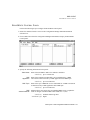
Navigate Configuration Explorer . . . . . . . . . . . . . . . . . . . . . . . . . . . . . . . . . . . . . . 34
Configure Alarms Sequence . . . . . . . . . . . . . . . . . . . . . . . . . . . . . . . . . . . . . . . . . . 40
AlarmViewer Design . . . . . . . . . . . . . . . . . . . . . . . . . . . . . . . . . . . . . . . . . . . . . . . 75
Run-Time Alarming . . . . . . . . . . . . . . . . . . . . . . . . . . . . . . . . . . . . . . . . . . . . . . . . . . . . . 117
AlarmViewer Format at Run Time . . . . . . . . . . . . . . . . . . . . . . . . . . . . . . . . . . . . 117
Alarm Band Viewer Format at Run Time . . . . . . . . . . . . . . . . . . . . . . . . . . . . . . . 119
Acknowledgement of Alarms . . . . . . . . . . . . . . . . . . . . . . . . . . . . . . . . . . . . . . . . 120
Multiple Instances of an Alarm . . . . . . . . . . . . . . . . . . . . . . . . . . . . . . . . . . . . . . . 121
Filter and Sort Alarms at Run Time . . . . . . . . . . . . . . . . . . . . . . . . . . . . . . . . . . . 121
Printing from the Viewers . . . . . . . . . . . . . . . . . . . . . . . . . . . . . . . . . . . . . . . . . . . 125
Browsing Archived Alarms . . . . . . . . . . . . . . . . . . . . . . . . . . . . . . . . . . . . . . . . . . 127
Properties, Methods, and Events . . . . . . . . . . . . . . . . . . . . . . . . . . . . . . . . . . . . . . . . . . . 128
Error Messages . . . . . . . . . . . . . . . . . . . . . . . . . . . . . . . . . . . . . . . . . . . . . . . . . . . . . . . . . 134
FactoryLink / Task Configuration Reference Guide / 3
•
•
•
•
Chapter 2
Batch Recipe . . . . . . . . . . . . . . . . . . . . . . . . . . . . . . . . . . . . . . . . . . . . . . 143
Principles of Operation. . . . . . . . . . . . . . . . . . . . . . . . . . . . . . . . . . . . . . . . . . . . . . . . . . .
Recipe Control Panel . . . . . . . . . . . . . . . . . . . . . . . . . . . . . . . . . . . . . . . . . . . . . . . . . . . .
Recipe Information Panel . . . . . . . . . . . . . . . . . . . . . . . . . . . . . . . . . . . . . . . . . . . . . . . . .
Completing a Protocol Module Read/Write Table . . . . . . . . . . . . . . . . . . . . . . . . . . . . . .
Drawing and Animating a Graphics Display . . . . . . . . . . . . . . . . . . . . . . . . . . . .
Configuring a Batch Recipe Template . . . . . . . . . . . . . . . . . . . . . . . . . . . . . . . . .
Linking Recipe Input Values to an External Device . . . . . . . . . . . . . . . . . . . . . . .
Batch Recipe Error Messages. . . . . . . . . . . . . . . . . . . . . . . . . . . . . . . . . . . . . . . . . . . . . .
Chapter 3
Browsing Databases . . . . . . . . . . . . . . . . . . . . . . . . . . . . . . . . . . . . . . . . 163
Browser Operating Principles . . . . . . . . . . . . . . . . . . . . . . . . . . . . . . . . . . . . . . . . . . . . .
About ActiveX Controls . . . . . . . . . . . . . . . . . . . . . . . . . . . . . . . . . . . . . . . . . . . .
Configuring the Database Browser Control Environment . . . . . . . . . . . . . . . . . . . . . . . .
Design Mode and Run Mode . . . . . . . . . . . . . . . . . . . . . . . . . . . . . . . . . . . . . . . .
Opening a New Project . . . . . . . . . . . . . . . . . . . . . . . . . . . . . . . . . . . . . . . . . . . .
Opening an Existing Project . . . . . . . . . . . . . . . . . . . . . . . . . . . . . . . . . . . . . . . . .
Opening Mimics . . . . . . . . . . . . . . . . . . . . . . . . . . . . . . . . . . . . . . . . . . . . . . . . . .
Configuring the USDATADbBrowseCtl Properties Window . . . . . . . . . . . . . . . . .
Configuring the General Tab . . . . . . . . . . . . . . . . . . . . . . . . . . . . . . . . . . . . . . . .
Configuring the Data Source Properties Tab . . . . . . . . . . . . . . . . . . . . . . . . . . . .
Configuring the Column Properties Tab . . . . . . . . . . . . . . . . . . . . . . . . . . . . . . . .
Run-Time Browsing . . . . . . . . . . . . . . . . . . . . . . . . . . . . . . . . . . . . . . . . . . . . . . . . . . . . .
Setting Up Control . . . . . . . . . . . . . . . . . . . . . . . . . . . . . . . . . . . . . . . . . . . . . . . .
Chapter 4
164
165
167
167
167
168
169
170
171
173
174
177
177
Database Logger . . . . . . . . . . . . . . . . . . . . . . . . . . . . . . . . . . . . . . . . . . . 179
Database Control Panel . . . . . . . . . . . . . . . . . . . . . . . . . . . . . . . . . . . . . . . . . . . . . . . . . .
Database Logging Information Panel. . . . . . . . . . . . . . . . . . . . . . . . . . . . . . . . . . . . . . . .
Configuring Program Arguments . . . . . . . . . . . . . . . . . . . . . . . . . . . . . . . . . . . . . . . . . . .
.....................................................................
Chapter 5
144
146
150
152
152
153
156
158
180
196
208
210
Configuring Data Point Logging . . . . . . . . . . . . . . . . . . . . . . . . . . . . . . 211
Data Point Logger Control Panel . . . . . . . . . . . . . . . . . . . . . . . . . . . . . . . . . . . . . . . . . . . 213
Data Point Logger Information Panel . . . . . . . . . . . . . . . . . . . . . . . . . . . . . . . . . . . . . . . 215
Data Point Schema Control Panel . . . . . . . . . . . . . . . . . . . . . . . . . . . . . . . . . . . . . . . . . . 217
4 / FactoryLink / Task Configuration Reference Guide
Logging Messages and Codes . . . . . . . . . . . . . . . . . . . . . . . . . . . . . . . . . . . . . . . . . . . . . 220
Error Detection . . . . . . . . . . . . . . . . . . . . . . . . . . . . . . . . . . . . . . . . . . . . . . . . . . 220
Messages . . . . . . . . . . . . . . . . . . . . . . . . . . . . . . . . . . . . . . . . . . . . . . . . . . . . . . . 221
Chapter 6
Dynamic Data Exchange (DDE) Task Definition . . . . . . . . . . . . . . . . . 227
Principles of Operation. . . . . . . . . . . . . . . . . . . . . . . . . . . . . . . . . . . . . . . . . . . . . . . . . . .
DDE Messages . . . . . . . . . . . . . . . . . . . . . . . . . . . . . . . . . . . . . . . . . . . . . . . . . . .
Setting Up DDE Server . . . . . . . . . . . . . . . . . . . . . . . . . . . . . . . . . . . . . . . . . . . . . . . . . .
Establishing a DDE Link . . . . . . . . . . . . . . . . . . . . . . . . . . . . . . . . . . . . . . . . . . . . . . . . .
Using a DDE Formula . . . . . . . . . . . . . . . . . . . . . . . . . . . . . . . . . . . . . . . . . . . . .
Using a Create Link Option . . . . . . . . . . . . . . . . . . . . . . . . . . . . . . . . . . . . . . . . .
DDE Client Functions . . . . . . . . . . . . . . . . . . . . . . . . . . . . . . . . . . . . . . . . . . . . . . . . . . .
Read Operations . . . . . . . . . . . . . . . . . . . . . . . . . . . . . . . . . . . . . . . . . . . . . . . . .
Write Operations . . . . . . . . . . . . . . . . . . . . . . . . . . . . . . . . . . . . . . . . . . . . . . . . .
Setting Up DDE Client. . . . . . . . . . . . . . . . . . . . . . . . . . . . . . . . . . . . . . . . . . . . . . . . . . .
Chapter 7
DDE Client . . . . . . . . . . . . . . . . . . . . . . . . . . . . . . . . . . . . . . . . . . . . . . . 239
Principles of Operation . . . . . . . . . . . . . . . . . . . . . . . . . . . . . . . . . . . . . . . . . . . .
DDE Conversations . . . . . . . . . . . . . . . . . . . . . . . . . . . . . . . . . . . . . . . . . . . . . . .
Establishing a DDE Link . . . . . . . . . . . . . . . . . . . . . . . . . . . . . . . . . . . . . . . . . . .
Setting Up DDE Client . . . . . . . . . . . . . . . . . . . . . . . . . . . . . . . . . . . . . . . . . . . . .
Read/Write Control Panel. . . . . . . . . . . . . . . . . . . . . . . . . . . . . . . . . . . . . . . . . . . . . . . . .
Read/Write Information Panel . . . . . . . . . . . . . . . . . . . . . . . . . . . . . . . . . . . . . . . . . . . . .
DDE Messages . . . . . . . . . . . . . . . . . . . . . . . . . . . . . . . . . . . . . . . . . . . . . . . . . . . . . . . . .
Server . . . . . . . . . . . . . . . . . . . . . . . . . . . . . . . . . . . . . . . . . . . . . . . . . . . . . . . . .
Client . . . . . . . . . . . . . . . . . . . . . . . . . . . . . . . . . . . . . . . . . . . . . . . . . . . . . . . . . .
Chapter 8
228
231
232
233
234
234
236
236
237
238
239
239
240
240
241
245
246
246
246
File Manager . . . . . . . . . . . . . . . . . . . . . . . . . . . . . . . . . . . . . . . . . . . . . 249
Principles of Operation. . . . . . . . . . . . . . . . . . . . . . . . . . . . . . . . . . . . . . . . . . . . . . . . . . .
File Manager Control Panel . . . . . . . . . . . . . . . . . . . . . . . . . . . . . . . . . . . . . . . . . . . . . . .
File Manager Information Panel. . . . . . . . . . . . . . . . . . . . . . . . . . . . . . . . . . . . . . . . . . . .
Sample File Manager Operations . . . . . . . . . . . . . . . . . . . . . . . . . . . . . . . . . . . . . . . . . . .
Example 1: COPY . . . . . . . . . . . . . . . . . . . . . . . . . . . . . . . . . . . . . . . . . . . . . . . .
Example 2: PRINT . . . . . . . . . . . . . . . . . . . . . . . . . . . . . . . . . . . . . . . . . . . . . . . .
Example 3: REN (Rename) . . . . . . . . . . . . . . . . . . . . . . . . . . . . . . . . . . . . . . . . . .
Example 4: TYPE . . . . . . . . . . . . . . . . . . . . . . . . . . . . . . . . . . . . . . . . . . . . . . . . .
250
251
258
260
260
262
263
264
FactoryLink / Task Configuration Reference Guide / 5
•
•
•
•
Example 5: DIR (Directory) . . . . . . . . . . . . . . . . . . . . . . . . . . . . . . . . . . . . . . . .
Example 6: DEL (Delete) . . . . . . . . . . . . . . . . . . . . . . . . . . . . . . . . . . . . . . . . . . .
Using Variable Specifiers in File Specifications . . . . . . . . . . . . . . . . . . . . . . . . . . . . . . .
Using Wildcard Characters in File Specifications . . . . . . . . . . . . . . . . . . . . . . . . . . . . . .
Using the File Manager with Networks . . . . . . . . . . . . . . . . . . . . . . . . . . . . . . . . . . . . . .
Using the COPY Command with FLLAN . . . . . . . . . . . . . . . . . . . . . . . . . . . . . . .
Using the COPY Command with a Network Without FLLAN . . . . . . . . . . . . . . . .
Changing Protocols . . . . . . . . . . . . . . . . . . . . . . . . . . . . . . . . . . . . . . . . . . . . . . . . . . . . .
Program Arguments . . . . . . . . . . . . . . . . . . . . . . . . . . . . . . . . . . . . . . . . . . . . . . . . . . . . .
File Manager Error Messages. . . . . . . . . . . . . . . . . . . . . . . . . . . . . . . . . . . . . . . . . . . . . .
Chapter 9
265
266
267
269
271
272
273
274
277
278
FactoryLink Local Area Networking. . . . . . . . . . . . . . . . . . . . . . . . . . . 287
Sending and Receiving Data . . . . . . . . . . . . . . . . . . . . . . . . . . . . . . . . . . . . . . . . . . . . . .
Sending Values to Remote Stations . . . . . . . . . . . . . . . . . . . . . . . . . . . . . . . . . . . .
Receiving Values from Remote Stations . . . . . . . . . . . . . . . . . . . . . . . . . . . . . . . .
Local and Remote Stations. . . . . . . . . . . . . . . . . . . . . . . . . . . . . . . . . . . . . . . . . . . . . . . .
Network Groups . . . . . . . . . . . . . . . . . . . . . . . . . . . . . . . . . . . . . . . . . . . . . . . . . .
Using Multiple Platforms on a Network . . . . . . . . . . . . . . . . . . . . . . . . . . . . . . . .
Monitoring the Network . . . . . . . . . . . . . . . . . . . . . . . . . . . . . . . . . . . . . . . . . . . .
Local Station’s Default Values . . . . . . . . . . . . . . . . . . . . . . . . . . . . . . . . . . . . . . .
Ordering Tag Names . . . . . . . . . . . . . . . . . . . . . . . . . . . . . . . . . . . . . . . . . . . . . .
Defining the TCP/IP Hosts and Service Ports . . . . . . . . . . . . . . . . . . . . . . . . . . . . . . . . .
Interval Timer Information Panel . . . . . . . . . . . . . . . . . . . . . . . . . . . . . . . . . . . . . . . . . . .
288
288
288
289
289
289
289
289
289
290
292
Chapter 10 Testing the Network Connection . . . . . . . . . . . . . . . . . . . . . . . . . . . . . . 295
NR and NS Test Programs . . . . . . . . . . . . . . . . . . . . . . . . . . . . . . . . . . . . . . . . . . . . . . . . 296
Chapter 11 Naming the Stations and Network Groups . . . . . . . . . . . . . . . . . . . . . . 299
LAN Local Names Panel . . . . . . . . . . . . . . . . . . . . . . . . . . . . . . . . . . . . . . . . . . . . . . . . . 300
Local Station Transmit Parameters and Default Values . . . . . . . . . . . . . . . . . . . . 301
LAN Remote Names Panel . . . . . . . . . . . . . . . . . . . . . . . . . . . . . . . . . . . . . . . . . . . . . . . 305
Chapter 12 Sending Element Values to Other Stations . . . . . . . . . . . . . . . . . . . . . . 307
LAN Send Control Panel . . . . . . . . . . . . . . . . . . . . . . . . . . . . . . . . . . . . . . . . . . . . . . . . . 308
LAN Send Information Panel. . . . . . . . . . . . . . . . . . . . . . . . . . . . . . . . . . . . . . . . . . . . . . 312
6 / FactoryLink / Task Configuration Reference Guide
Chapter 13 Receiving Element Values from Remote Stations . . . . . . . . . . . . . . . . . 315
LAN Receive Control Panel. . . . . . . . . . . . . . . . . . . . . . . . . . . . . . . . . . . . . . . . . . . . . . . 316
LAN Receive Information Panel . . . . . . . . . . . . . . . . . . . . . . . . . . . . . . . . . . . . . . . . . . . 318
Chapter 14 Monitoring Remote Station Communications . . . . . . . . . . . . . . . . . . . . 321
Network Monitor Information Panel . . . . . . . . . . . . . . . . . . . . . . . . . . . . . . . . . . . . . . . . 322
Chapter 15 Configuring the System to Work with a Historian . . . . . . . . . . . . . . . . 327
Setting Program Arguments to Generate/Create Log files. . . . . . . . . . . . . . . . . . . . . . . .
Setting Historian Run-Time Parameters. . . . . . . . . . . . . . . . . . . . . . . . . . . . . . . . . . . . . .
Database Disconnects and Reconnects. . . . . . . . . . . . . . . . . . . . . . . . . . . . . . . . . . . . . . .
Scheduled Disconnects . . . . . . . . . . . . . . . . . . . . . . . . . . . . . . . . . . . . . . . . . . . . .
Database Reconnect . . . . . . . . . . . . . . . . . . . . . . . . . . . . . . . . . . . . . . . . . . . . . . .
Setting Run-Time Fatal Error Code Values . . . . . . . . . . . . . . . . . . . . . . . . . . . . . . . . . . .
Handling Fatal Errors . . . . . . . . . . . . . . . . . . . . . . . . . . . . . . . . . . . . . . . . . . . . .
328
329
336
336
337
338
340
Chapter 16 Configuring Oracle Historians . . . . . . . . . . . . . . . . . . . . . . . . . . . . . . . 343
Oracle Historian Considerations . . . . . . . . . . . . . . . . . . . . . . . . . . . . . . . . . . . . . . . . . . .
Network Software Needed . . . . . . . . . . . . . . . . . . . . . . . . . . . . . . . . . . . . . . . . . .
Oracle Licenses . . . . . . . . . . . . . . . . . . . . . . . . . . . . . . . . . . . . . . . . . . . . . . . . . .
Number of Cursors per User . . . . . . . . . . . . . . . . . . . . . . . . . . . . . . . . . . . . . . . .
Data Types Supported by Oracle Database . . . . . . . . . . . . . . . . . . . . . . . . . . . . .
Historian Mailbox Information for Oracle Panel . . . . . . . . . . . . . . . . . . . . . . . . . . . . . . .
Historian Information for Oracle Panel . . . . . . . . . . . . . . . . . . . . . . . . . . . . . . . . . . . . . .
Connecting the Historian to an Oracle Database . . . . . . . . . . . . . . . . . . . . . . . . . . . . . . .
Granting the FactoryLink Account Oracle Access . . . . . . . . . . . . . . . . . . . . . . . .
Setting Connection Strings . . . . . . . . . . . . . . . . . . . . . . . . . . . . . . . . . . . . . . . . . .
344
344
344
344
345
346
347
350
350
350
Chapter 17 Configuring Multi-Instance ODBC Historian . . . . . . . . . . . . . . . . . . . 353
FactoryLink ODBC Overview . . . . . . . . . . . . . . . . . . . . . . . . . . . . . . . . . . . . . . . . . . . . .
ODBC Historian Considerations . . . . . . . . . . . . . . . . . . . . . . . . . . . . . . . . . . . . . . . . . . .
Supported Drivers . . . . . . . . . . . . . . . . . . . . . . . . . . . . . . . . . . . . . . . . . . . . . . . .
Conformance Levels . . . . . . . . . . . . . . . . . . . . . . . . . . . . . . . . . . . . . . . . . . . . . . .
SQL Statements . . . . . . . . . . . . . . . . . . . . . . . . . . . . . . . . . . . . . . . . . . . . . . . . . .
354
355
355
356
356
FactoryLink / Task Configuration Reference Guide / 7
•
•
•
•
Setting Up ODBC in FactoryLink . . . . . . . . . . . . . . . . . . . . . . . . . . . . . . . . . . . . . . . . . .
Data Types Supported by ODBC Driver . . . . . . . . . . . . . . . . . . . . . . . . . . . . . . . .
Conversion Issue . . . . . . . . . . . . . . . . . . . . . . . . . . . . . . . . . . . . . . . . . . . . . . . . .
Setting up the ODBC Drivers and Data Sources . . . . . . . . . . . . . . . . . . . . . . . . . . . . . . .
Drivers and Data Sources . . . . . . . . . . . . . . . . . . . . . . . . . . . . . . . . . . . . . . . . . .
Defining Drivers . . . . . . . . . . . . . . . . . . . . . . . . . . . . . . . . . . . . . . . . . . . . . . . . .
Historian Configuration Panels for ODBC . . . . . . . . . . . . . . . . . . . . . . . . . . . . . . . . . . .
Historian Instance Number Panel for ODBC . . . . . . . . . . . . . . . . . . . . . . . . . . . . . . . . . .
Historian Mailbox Information Panel for ODBC. . . . . . . . . . . . . . . . . . . . . . . . . . . . . . .
Historian Information Panel for ODBC . . . . . . . . . . . . . . . . . . . . . . . . . . . . . . . . . . . . . .
Executing Multiple Instances of the ODBC Historian . . . . . . . . . . . . . . . . . . . . . . . . . . .
Administrative Duties . . . . . . . . . . . . . . . . . . . . . . . . . . . . . . . . . . . . . . . . . . . . . .
Maintaining Drivers and Data Sources . . . . . . . . . . . . . . . . . . . . . . . . . . . . . . . .
Testing Unsupported Drivers . . . . . . . . . . . . . . . . . . . . . . . . . . . . . . . . . . . . . . . .
357
357
357
358
358
359
367
369
370
371
374
374
374
375
Chapter 18 Configuring Sybase Historian . . . . . . . . . . . . . . . . . . . . . . . . . . . . . . . . 377
Sybase Historian Considerations . . . . . . . . . . . . . . . . . . . . . . . . . . . . . . . . . . . . . . . . . . .
Historian Mailbox Information for Sybase Panel. . . . . . . . . . . . . . . . . . . . . . . . . . . . . . .
Historian Information for Sybase Panel . . . . . . . . . . . . . . . . . . . . . . . . . . . . . . . . . . . . . .
User Access to Server and Database . . . . . . . . . . . . . . . . . . . . . . . . . . . . . . . . . . . . . . . .
Setting the Sybase Interfaces File for FactoryLink . . . . . . . . . . . . . . . . . . . . . . . .
Granting FactoryLink Users Access to Create Commands . . . . . . . . . . . . . . . . . . . . . . .
378
379
380
383
383
384
Chapter 19 Troubleshooting . . . . . . . . . . . . . . . . . . . . . . . . . . . . . . . . . . . . . . . . . . . 385
Troubleshooting ODBC Driver . . . . . . . . . . . . . . . . . . . . . . . . . . . . . . . . . . . . . . . . . . . .
Historian Messages. . . . . . . . . . . . . . . . . . . . . . . . . . . . . . . . . . . . . . . . . . . . . . . . . . . . . .
Run-time Messages . . . . . . . . . . . . . . . . . . . . . . . . . . . . . . . . . . . . . . . . . . . . . . .
Start-up Messages . . . . . . . . . . . . . . . . . . . . . . . . . . . . . . . . . . . . . . . . . . . . . . . .
Error Messages Recorded in Historian Log Files . . . . . . . . . . . . . . . . . . . . . . . . .
ODBC Driver and Data Source Messages . . . . . . . . . . . . . . . . . . . . . . . . . . . . . .
389
390
390
395
397
398
Chapter 20 Configuring Math and Logic . . . . . . . . . . . . . . . . . . . . . . . . . . . . . . . . . 401
Locating Math and Logic Functions in Configuration Explorer . . . . . . . . . . . . . . . . . . .
Launch Configuration Explorer . . . . . . . . . . . . . . . . . . . . . . . . . . . . . . . . . . . . . .
Locate Math and Logic Tasks, Tables and Editor . . . . . . . . . . . . . . . . . . . . . . . . .
Configure Math and Logic Tasks . . . . . . . . . . . . . . . . . . . . . . . . . . . . . . . . . . . . . . . . . . .
8 / FactoryLink / Task Configuration Reference Guide
404
405
406
409
Configure Math and Logic Tables . . . . . . . . . . . . . . . . . . . . . . . . . . . . . . . . . . . . . . . . . .
Math and Logic Variables . . . . . . . . . . . . . . . . . . . . . . . . . . . . . . . . . . . . . . . . . .
Math and Logic Triggers . . . . . . . . . . . . . . . . . . . . . . . . . . . . . . . . . . . . . . . . . . .
Program Files and Procedures . . . . . . . . . . . . . . . . . . . . . . . . . . . . . . . . . . . . . . . . . . . . .
Defining a New Program File . . . . . . . . . . . . . . . . . . . . . . . . . . . . . . . . . . . . . . .
Add New Procedures . . . . . . . . . . . . . . . . . . . . . . . . . . . . . . . . . . . . . . . . . . . . . .
Customize the Procedure Header File for the FactoryLink Server . . . . . . . . . . . .
Modify Makefiles . . . . . . . . . . . . . . . . . . . . . . . . . . . . . . . . . . . . . . . . . . . . . . . . . . . . . . .
Math and Logic System Makefile . . . . . . . . . . . . . . . . . . . . . . . . . . . . . . . . . . . . .
Math and Logic Domain Makefile . . . . . . . . . . . . . . . . . . . . . . . . . . . . . . . . . . . .
Compiled Math and Logic (CML) . . . . . . . . . . . . . . . . . . . . . . . . . . . . . . . . . . . . . . . . . .
CML Requirements . . . . . . . . . . . . . . . . . . . . . . . . . . . . . . . . . . . . . . . . . . . . . . .
Running CML . . . . . . . . . . . . . . . . . . . . . . . . . . . . . . . . . . . . . . . . . . . . . . . . . . .
CML Utilities Call Sequence . . . . . . . . . . . . . . . . . . . . . . . . . . . . . . . . . . . . . . . . . . . . . .
MKCML . . . . . . . . . . . . . . . . . . . . . . . . . . . . . . . . . . . . . . . . . . . . . . . . . . . . . . .
PARSECML . . . . . . . . . . . . . . . . . . . . . . . . . . . . . . . . . . . . . . . . . . . . . . . . . . . . .
CCCML . . . . . . . . . . . . . . . . . . . . . . . . . . . . . . . . . . . . . . . . . . . . . . . . . . . . . . . .
CML Variables . . . . . . . . . . . . . . . . . . . . . . . . . . . . . . . . . . . . . . . . . . . . . . . . . . . . . . . . .
Running the Utilities from the Command Prompt Window . . . . . . . . . . . . . . . . . .
Verbose-Level Parameters . . . . . . . . . . . . . . . . . . . . . . . . . . . . . . . . . . . . . . . . . .
Calling C Code . . . . . . . . . . . . . . . . . . . . . . . . . . . . . . . . . . . . . . . . . . . . . . . . . . . . . . . .
Using cfunc . . . . . . . . . . . . . . . . . . . . . . . . . . . . . . . . . . . . . . . . . . . . . . . . . . . . .
cfunc Examples . . . . . . . . . . . . . . . . . . . . . . . . . . . . . . . . . . . . . . . . . . . . . . . . . .
Using cbegin and cend . . . . . . . . . . . . . . . . . . . . . . . . . . . . . . . . . . . . . . . . . . . . .
Math and Logic Editor Reference Pages . . . . . . . . . . . . . . . . . . . . . . . . . . . . . . . . . . . . .
Math and Logic Editor Icons . . . . . . . . . . . . . . . . . . . . . . . . . . . . . . . . . . . . . . . .
Mouse Functions . . . . . . . . . . . . . . . . . . . . . . . . . . . . . . . . . . . . . . . . . . . . . . . . .
Keyboard Shortcuts . . . . . . . . . . . . . . . . . . . . . . . . . . . . . . . . . . . . . . . . . . . . . . .
Chromocoding . . . . . . . . . . . . . . . . . . . . . . . . . . . . . . . . . . . . . . . . . . . . . . . . . . .
Menu Commands . . . . . . . . . . . . . . . . . . . . . . . . . . . . . . . . . . . . . . . . . . . . . . . . .
412
412
415
418
420
424
428
431
432
432
434
434
435
437
438
438
438
439
440
441
442
442
443
444
449
450
451
452
455
455
Chapter 21 Persistence . . . . . . . . . . . . . . . . . . . . . . . . . . . . . . . . . . . . . . . . . . . . . . . 459
Persistence Overview . . . . . . . . . . . . . . . . . . . . . . . . . . . . . . . . . . . . . . . . . . . . . . . . . . . .
Principles of Operation. . . . . . . . . . . . . . . . . . . . . . . . . . . . . . . . . . . . . . . . . . . . . . . . . . .
Performing a Warm Start . . . . . . . . . . . . . . . . . . . . . . . . . . . . . . . . . . . . . . . . . . .
Resolving Configuration Changes . . . . . . . . . . . . . . . . . . . . . . . . . . . . . . . . . . . .
Configuring Persistence . . . . . . . . . . . . . . . . . . . . . . . . . . . . . . . . . . . . . . . . . . . . . . . . . .
460
461
461
462
463
FactoryLink / Task Configuration Reference Guide / 9
•
•
•
•
Marking Elements to be Persistent . . . . . . . . . . . . . . . . . . . . . . . . . . . . . . . . . . . .
Configuring the Persistence Task . . . . . . . . . . . . . . . . . . . . . . . . . . . . . . . . . . . . .
Persistence Task Start Order. . . . . . . . . . . . . . . . . . . . . . . . . . . . . . . . . . . . . . . . . . . . . . .
Persistence and Digital Elements . . . . . . . . . . . . . . . . . . . . . . . . . . . . . . . . . . . . . . . . . . .
Examples . . . . . . . . . . . . . . . . . . . . . . . . . . . . . . . . . . . . . . . . . . . . . . . . . . . . . . .
Persistence Save File Name . . . . . . . . . . . . . . . . . . . . . . . . . . . . . . . . . . . . . . . . . . . . . . .
Editing Tag Persistence Settings Using BH_SQL Utility . . . . . . . . . . . . . . . . . . . . . . . .
Persistence Error Messages . . . . . . . . . . . . . . . . . . . . . . . . . . . . . . . . . . . . . . . . . . . . . . .
463
467
470
471
471
473
474
476
Chapter 22 Programmable Counters . . . . . . . . . . . . . . . . . . . . . . . . . . . . . . . . . . . . 479
Principles of Operation. . . . . . . . . . . . . . . . . . . . . . . . . . . . . . . . . . . . . . . . . . . . . . . . . . .
Elements . . . . . . . . . . . . . . . . . . . . . . . . . . . . . . . . . . . . . . . . . . . . . . . . . . . . . . .
Digital and Analog Values . . . . . . . . . . . . . . . . . . . . . . . . . . . . . . . . . . . . . . . . . .
Example One . . . . . . . . . . . . . . . . . . . . . . . . . . . . . . . . . . . . . . . . . . . . . . . . . . . .
Example Two . . . . . . . . . . . . . . . . . . . . . . . . . . . . . . . . . . . . . . . . . . . . . . . . . . . .
Programmable Counters Information Panel . . . . . . . . . . . . . . . . . . . . . . . . . . . . . . . . . . .
Programmable Counters Error Messages . . . . . . . . . . . . . . . . . . . . . . . . . . . . . . . . . . . . .
480
480
480
481
481
482
487
Chapter 23 Defining the Report Format. . . . . . . . . . . . . . . . . . . . . . . . . . . . . . . . . . 489
Reporting Methodology . . . . . . . . . . . . . . . . . . . . . . . . . . . . . . . . . . . . . . . . . . . . . . . . . .
Components of a Format File. . . . . . . . . . . . . . . . . . . . . . . . . . . . . . . . . . . . . . . . . . . . . .
Keywords . . . . . . . . . . . . . . . . . . . . . . . . . . . . . . . . . . . . . . . . . . . . . . . . . . . . . . .
Sections of Format File . . . . . . . . . . . . . . . . . . . . . . . . . . . . . . . . . . . . . . . . . . . .
Placement of Reported Data. . . . . . . . . . . . . . . . . . . . . . . . . . . . . . . . . . . . . . . . . . . . . . .
Location of Object Name . . . . . . . . . . . . . . . . . . . . . . . . . . . . . . . . . . . . . . . . . . .
Format Specifiers . . . . . . . . . . . . . . . . . . . . . . . . . . . . . . . . . . . . . . . . . . . . . . . . .
Trigger Actions. . . . . . . . . . . . . . . . . . . . . . . . . . . . . . . . . . . . . . . . . . . . . . . . . . . . . . . . .
Report Format Variations . . . . . . . . . . . . . . . . . . . . . . . . . . . . . . . . . . . . . . . . . . . . . . . . .
Complete Triggers . . . . . . . . . . . . . . . . . . . . . . . . . . . . . . . . . . . . . . . . . . . . . . . . . . . . . .
Escape Sequences. . . . . . . . . . . . . . . . . . . . . . . . . . . . . . . . . . . . . . . . . . . . . . . . . . . . . . .
Configuring the Report Format File. . . . . . . . . . . . . . . . . . . . . . . . . . . . . . . . . . . . . . . . .
490
492
492
492
494
494
494
496
499
500
501
502
Chapter 24 Defining the Reporting Operation . . . . . . . . . . . . . . . . . . . . . . . . . . . . . 507
Report Generator Control Panel . . . . . . . . . . . . . . . . . . . . . . . . . . . . . . . . . . . . . . . . . . . . 508
Report Generator Information Panel . . . . . . . . . . . . . . . . . . . . . . . . . . . . . . . . . . . . . . . . 515
10 / FactoryLink / Task Configuration Reference Guide
Chapter 25 Scaling and Deadbanding . . . . . . . . . . . . . . . . . . . . . . . . . . . . . . . . . . . 519
Scaling and Deadbanding Overview . . . . . . . . . . . . . . . . . . . . . . . . . . . . . . . . . . . . . . . .
Principles of Operation. . . . . . . . . . . . . . . . . . . . . . . . . . . . . . . . . . . . . . . . . . . . . . . . . . .
Scaling and Deadbanding Information Panel. . . . . . . . . . . . . . . . . . . . . . . . . . . . . . . . . .
Scaling and Deadbanding Error Messages . . . . . . . . . . . . . . . . . . . . . . . . . . . . . . . . . . . .
520
521
522
525
Chapter 26 Defining Schemas. . . . . . . . . . . . . . . . . . . . . . . . . . . . . . . . . . . . . . . . . . 531
Schema Control Panel . . . . . . . . . . . . . . . . . . . . . . . . . . . . . . . . . . . . . . . . . . . . . . . . . . .
Schema Information Panel . . . . . . . . . . . . . . . . . . . . . . . . . . . . . . . . . . . . . . . . . . . . . . . .
Index Information Panel. . . . . . . . . . . . . . . . . . . . . . . . . . . . . . . . . . . . . . . . . . . . . . . . . .
Security Event Logging Schema Panel . . . . . . . . . . . . . . . . . . . . . . . . . . . . . . . . . . . . . .
Data Point Logging . . . . . . . . . . . . . . . . . . . . . . . . . . . . . . . . . . . . . . . . . . . . . . . . . . . . .
Data Point Schema Control Panel . . . . . . . . . . . . . . . . . . . . . . . . . . . . . . . . . . . . . . . . . .
Data Point Logging Control Panel . . . . . . . . . . . . . . . . . . . . . . . . . . . . . . . . . . . . . . . . . .
Chapter 27
532
535
539
542
545
546
548
Print Spooler . . . . . . . . . . . . . . . . . . . . . . . . . . . . . . . . . . . . . . . . . . . . . 551
Print Spooler Information Panel. . . . . . . . . . . . . . . . . . . . . . . . . . . . . . . . . . . . . . . . . . . . 552
Sample Print Spooler Configuration for Alarm Logger . . . . . . . . . . . . . . . . . . . . 557
Print Spooler Error Messages. . . . . . . . . . . . . . . . . . . . . . . . . . . . . . . . . . . . . . . . . . . . . . 558
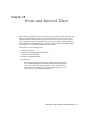
Chapter 28 Event and Interval Timer . . . . . . . . . . . . . . . . . . . . . . . . . . . . . . . . . . . . 561
Principles of Operation. . . . . . . . . . . . . . . . . . . . . . . . . . . . . . . . . . . . . . . . . . . . . . . . . . .
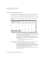
Event Timer Information Panel . . . . . . . . . . . . . . . . . . . . . . . . . . . . . . . . . . . . . . . . . . . .
Interval Timer Information Panel. . . . . . . . . . . . . . . . . . . . . . . . . . . . . . . . . . . . . . . . . . .
Event and Interval Timer Error Messages . . . . . . . . . . . . . . . . . . . . . . . . . . . . . . . . . . . .
562
564
567
570
Chapter 29 Trending Task . . . . . . . . . . . . . . . . . . . . . . . . . . . . . . . . . . . . . . . . . . . . . 575
Trending Operating Principles . . . . . . . . . . . . . . . . . . . . . . . . . . . . . . . . . . . . . . . . . . . . .
Historical Trending . . . . . . . . . . . . . . . . . . . . . . . . . . . . . . . . . . . . . . . . . . . . . . .
Trend Components . . . . . . . . . . . . . . . . . . . . . . . . . . . . . . . . . . . . . . . . . . . . . . . .
Trend Component Interaction . . . . . . . . . . . . . . . . . . . . . . . . . . . . . . . . . . . . . . . .
Trend Cluster . . . . . . . . . . . . . . . . . . . . . . . . . . . . . . . . . . . . . . . . . . . . . . . . . . . .
Chart Types . . . . . . . . . . . . . . . . . . . . . . . . . . . . . . . . . . . . . . . . . . . . . . . . . . . . .
Panning & Zooming . . . . . . . . . . . . . . . . . . . . . . . . . . . . . . . . . . . . . . . . . . . . . . .
Multiple Pens . . . . . . . . . . . . . . . . . . . . . . . . . . . . . . . . . . . . . . . . . . . . . . . . . . . .
576
577
577
578
579
580
583
584
FactoryLink / Task Configuration Reference Guide / 11
•
•
•
•
Value Cursor . . . . . . . . . . . . . . . . . . . . . . . . . . . . . . . . . . . . . . . . . . . . . . . . . . . .
Multiple Axes . . . . . . . . . . . . . . . . . . . . . . . . . . . . . . . . . . . . . . . . . . . . . . . . . . . .
Delta T . . . . . . . . . . . . . . . . . . . . . . . . . . . . . . . . . . . . . . . . . . . . . . . . . . . . . . . . .
Tooltip Information . . . . . . . . . . . . . . . . . . . . . . . . . . . . . . . . . . . . . . . . . . . . . . .
Custom Programming Capabilities . . . . . . . . . . . . . . . . . . . . . . . . . . . . . . . . . . .
Configuring Trend . . . . . . . . . . . . . . . . . . . . . . . . . . . . . . . . . . . . . . . . . . . . . . . . . . . . . .
Trend Server . . . . . . . . . . . . . . . . . . . . . . . . . . . . . . . . . . . . . . . . . . . . . . . . . . . . .
Trend Control . . . . . . . . . . . . . . . . . . . . . . . . . . . . . . . . . . . . . . . . . . . . . . . . . . . .
Predesign, Design & Run Time Phases . . . . . . . . . . . . . . . . . . . . . . . . . . . . . . . . .
Predesign . . . . . . . . . . . . . . . . . . . . . . . . . . . . . . . . . . . . . . . . . . . . . . . . . . . . . . .
Adding an ODBC Data Source . . . . . . . . . . . . . . . . . . . . . . . . . . . . . . . . . . . . . . .
Configuring an ODBC Data Source to use with dBASE IV . . . . . . . . . . . . . . . . . .
Setting up a Trend Server . . . . . . . . . . . . . . . . . . . . . . . . . . . . . . . . . . . . . . . . . . .
Setting Up a Trend Cluster . . . . . . . . . . . . . . . . . . . . . . . . . . . . . . . . . . . . . . . . . .
Design . . . . . . . . . . . . . . . . . . . . . . . . . . . . . . . . . . . . . . . . . . . . . . . . . . . . . . . . .
Adding Trend Control to the Active X Controls Configuration . . . . . . . . . . . . . . .
Inserting Trend Control into Client Builder . . . . . . . . . . . . . . . . . . . . . . . . . . . . .
Selecting A Trend Cluster . . . . . . . . . . . . . . . . . . . . . . . . . . . . . . . . . . . . . . . . . . .
Using the Trend Control Properties Graph Tab . . . . . . . . . . . . . . . . . . . . . . . . . .
Producing a Trend Chart of Near Real-Time Data . . . . . . . . . . . . . . . . . . . . . . . .
Configuring the Pens for the Trend Chart . . . . . . . . . . . . . . . . . . . . . . . . . . . . . . .
Adding a Database to Pen Configuration . . . . . . . . . . . . . . . . . . . . . . . . . . . . . . .
Adding a Table to Pen Configuration . . . . . . . . . . . . . . . . . . . . . . . . . . . . . . . . . .
Adding a Pen to the Pen Configuration . . . . . . . . . . . . . . . . . . . . . . . . . . . . . . . .
Configuring Pens Using the Setup Wizard . . . . . . . . . . . . . . . . . . . . . . . . . . . . . .
Adding a New Pen to the Trend Chart . . . . . . . . . . . . . . . . . . . . . . . . . . . . . . . . .
Using the Trend Control Properties Fonts Tab . . . . . . . . . . . . . . . . . . . . . . . . . . .
Custom Programming for the Pen Cursor Values . . . . . . . . . . . . . . . . . . . . . . . . .
Creating a Dynamic Pen through Custom Programming . . . . . . . . . . . . . . . . . . .
Run Time . . . . . . . . . . . . . . . . . . . . . . . . . . . . . . . . . . . . . . . . . . . . . . . . . . . . . . . . . . . . .
Using a Trend Chart . . . . . . . . . . . . . . . . . . . . . . . . . . . . . . . . . . . . . . . . . . . . . . .
Panning and Zooming . . . . . . . . . . . . . . . . . . . . . . . . . . . . . . . . . . . . . . . . . . . . .
584
584
585
585
585
586
586
586
587
588
588
595
597
600
603
604
605
606
609
616
621
621
625
631
634
635
639
641
642
644
644
649
Chapter 30 FactoryLink Utilities. . . . . . . . . . . . . . . . . . . . . . . . . . . . . . . . . . . . . . . . 655
CDBLIST . . . . . . . . . . . . . . . . . . . . . . . . . . . . . . . . . . . . . . . . . . . . . . . . . . . . . . . . . . . . . 658
CTGEN. . . . . . . . . . . . . . . . . . . . . . . . . . . . . . . . . . . . . . . . . . . . . . . . . . . . . . . . . . . . . . . 659
CTGEN in Configuration Explorer . . . . . . . . . . . . . . . . . . . . . . . . . . . . . . . . . . . . 659
12 / FactoryLink / Task Configuration Reference Guide
CTGEN in the Command Prompt Window . . . . . . . . . . . . . . . . . . . . . . . . . . . . . .
CTLIST . . . . . . . . . . . . . . . . . . . . . . . . . . . . . . . . . . . . . . . . . . . . . . . . . . . . . . . . . . . . . .
DBCHK . . . . . . . . . . . . . . . . . . . . . . . . . . . . . . . . . . . . . . . . . . . . . . . . . . . . . . . . . . . . . .
FLCONV . . . . . . . . . . . . . . . . . . . . . . . . . . . . . . . . . . . . . . . . . . . . . . . . . . . . . . . . . . . . .
FLCONV in Configuration Explorer . . . . . . . . . . . . . . . . . . . . . . . . . . . . . . . . . .
FLCONV in a Command Prompt Window . . . . . . . . . . . . . . . . . . . . . . . . . . . . . .
FLNEW . . . . . . . . . . . . . . . . . . . . . . . . . . . . . . . . . . . . . . . . . . . . . . . . . . . . . . . . . . . . . .
FLNEW in Configuration Explorer . . . . . . . . . . . . . . . . . . . . . . . . . . . . . . . . . . . .
FLNEW in the Command Prompt Window . . . . . . . . . . . . . . . . . . . . . . . . . . . . . .
FLREST . . . . . . . . . . . . . . . . . . . . . . . . . . . . . . . . . . . . . . . . . . . . . . . . . . . . . . . . . . . . . .
Native File Restore Method . . . . . . . . . . . . . . . . . . . . . . . . . . . . . . . . . . . . . . . . .
Compressed File Restore Method . . . . . . . . . . . . . . . . . . . . . . . . . . . . . . . . . . . . .
FLREST in Configuration Explorer . . . . . . . . . . . . . . . . . . . . . . . . . . . . . . . . . . .
Restore Binary, Log or Recipe Files . . . . . . . . . . . . . . . . . . . . . . . . . . . . . . . . . . .
Codepage Conversions . . . . . . . . . . . . . . . . . . . . . . . . . . . . . . . . . . . . . . . . . . . . .
FLREST in a Command Prompt Window . . . . . . . . . . . . . . . . . . . . . . . . . . . . . . .
FLRUN. . . . . . . . . . . . . . . . . . . . . . . . . . . . . . . . . . . . . . . . . . . . . . . . . . . . . . . . . . . . . . .
FLSAVE . . . . . . . . . . . . . . . . . . . . . . . . . . . . . . . . . . . . . . . . . . . . . . . . . . . . . . . . . . . . . .
Native File Save Method . . . . . . . . . . . . . . . . . . . . . . . . . . . . . . . . . . . . . . . . . . .
Compressed File Save Method . . . . . . . . . . . . . . . . . . . . . . . . . . . . . . . . . . . . . . .
FLSAVE in Configuration Explorer . . . . . . . . . . . . . . . . . . . . . . . . . . . . . . . . . . .
Save CML-binary, Log or Recipe files . . . . . . . . . . . . . . . . . . . . . . . . . . . . . . . . .
FLSAVE in the Command Prompt Window . . . . . . . . . . . . . . . . . . . . . . . . . . . . . .
Controlling the Files Included in Saves . . . . . . . . . . . . . . . . . . . . . . . . . . . . . . . .
FLSETLNG . . . . . . . . . . . . . . . . . . . . . . . . . . . . . . . . . . . . . . . . . . . . . . . . . . . . . . . . . . .
Initiate FLSETLNG . . . . . . . . . . . . . . . . . . . . . . . . . . . . . . . . . . . . . . . . . . . . . . .
Language Conversion Exceptions . . . . . . . . . . . . . . . . . . . . . . . . . . . . . . . . . . . .
Internationalization Considerations . . . . . . . . . . . . . . . . . . . . . . . . . . . . . . . . . . .
FLSHM. . . . . . . . . . . . . . . . . . . . . . . . . . . . . . . . . . . . . . . . . . . . . . . . . . . . . . . . . . . . . . .
FLSTATE . . . . . . . . . . . . . . . . . . . . . . . . . . . . . . . . . . . . . . . . . . . . . . . . . . . . . . . . . . . . .
NAMESPACE WIZARD . . . . . . . . . . . . . . . . . . . . . . . . . . . . . . . . . . . . . . . . . . . . . . . . .
RTDEBUG - Database Debugger. . . . . . . . . . . . . . . . . . . . . . . . . . . . . . . . . . . . . . . . . . .
RTMON . . . . . . . . . . . . . . . . . . . . . . . . . . . . . . . . . . . . . . . . . . . . . . . . . . . . . . . . . . . . . .
UKEY . . . . . . . . . . . . . . . . . . . . . . . . . . . . . . . . . . . . . . . . . . . . . . . . . . . . . . . . . . . . . . . .
FLTEST Application . . . . . . . . . . . . . . . . . . . . . . . . . . . . . . . . . . . . . . . . . . . . . . . . . . . .
FLBLANK Application . . . . . . . . . . . . . . . . . . . . . . . . . . . . . . . . . . . . . . . . . . . . . . . . . .
Utility Messages . . . . . . . . . . . . . . . . . . . . . . . . . . . . . . . . . . . . . . . . . . . . . . . . . . . . . . . .
EXPLODE . . . . . . . . . . . . . . . . . . . . . . . . . . . . . . . . . . . . . . . . . . . . . . . . . . . . . .
660
661
662
664
664
665
666
666
667
668
668
668
668
670
671
671
672
674
674
674
675
676
676
677
680
680
681
681
682
683
685
687
689
701
702
703
704
706
FactoryLink / Task Configuration Reference Guide / 13
•
•
•
•
FLSAVE . . . . . . . . . . . . . . . . . . . . . . . . . . . . . . . . . . . . . . . . . . . . . . . . . . . . . . . . 706
FLREST . . . . . . . . . . . . . . . . . . . . . . . . . . . . . . . . . . . . . . . . . . . . . . . . . . . . . . . . 708
Chapter 31 Glossary. . . . . . . . . . . . . . . . . . . . . . . . . . . . . . . . . . . . . . . . . . . . . . . . . . 711
Index . . . . . . . . . . . . . . . . . . . . . . . . . . . . . . . . . . . . . . . . . . . . . . . . . . . . 743
14 / FactoryLink / Task Configuration Reference Guide
Preface
The Task Configuration Reference Guide (TCR) presents basic concepts necessary to
understand how FactoryLink conversion works. It also provides the technical information to
users of FactoryLink systems who need to convert their applications from earlier versions of
FactoryLink to 7.0.
A UDIENCE
The major audience of this guide is users of early versions of FactoryLink who need to upgrade
their systems to the 7.0 version.
S TRUCTURE
G UIDE
OF THE
F ACTORY L INK TASK C ONFIGURATION R EFERENCE
This manual contains 30 chapters:
• Chapter 1, “Alarms”
• Chapter 2, “Batch Recipe”
• Chapter 3, “Browsing Databases”
• Chapter 4, “Database Logger”
• Chapter 5, “Configuring Data Point Logging”
• Chapter 6, “Dynamic Data Exchange (DDE) Task Definition”
• Chapter 7, “DDE Client”
• Chapter 8, “File Manager”
• Chapter 9, “FactoryLink Local Area Networking”
• Chapter 10, “Testing the Network Connection”
• Chapter 11, “Naming the Stations and Network Groups”
• Chapter 12, “Sending Element Values to Other Stations”
• Chapter 13, “Receiving Element Values from Remote Stations”
• Chapter 14, “Monitoring Remote Station Communications”
• Chapter 15, “Configuring the System to Work with a Historian”
• Chapter 16, “Configuring Oracle Historians”
• Chapter 17, “Configuring Multi-Instance ODBC Historian”
• Chapter 18, “Configuring Sybase Historian”
• Chapter 19, “Troubleshooting”
• Chapter 20, “Configuring Math and Logic”
• Chapter 21, “Persistence”
FactoryLink / Task Configuration Reference Guide / 15
PREFACE
How to Use This Guide
• Chapter 22, “Programmable Counters”
• Chapter 23, “Defining the Report Format”
• Chapter 24, “Defining the Reporting Operation”
• Chapter 25, “Scaling and Deadbanding”
• Chapter 26, “Defining Schemas”
• Chapter 27, “Print Spooler”
• Chapter 28, “Event and Interval Timer”
• Chapter 29, “Trending Task”
• Chapter 30, “FactoryLink Utilities”
The following chapters are brand new for 7.0 and all involve the new ActiveX controls:
• Chapter 1, "Alarms"
• Chapter 3, "Browsing Databases"
• Chapter 29, "Trending Task"
H OW
TO
U SE T HIS G UIDE
The material in this guide is presented in a learning order. We recommend you read the entire
guide to familiarize yourself with all the information before you proceed to convert your
application.
G ETTING H ELP
For help, contact your USDATA Tier One Partner (TOP) or visit the USDATA Web site
(www.USDATA.com) to locate a TOP in your region.
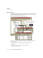
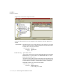
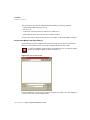
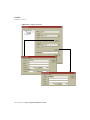
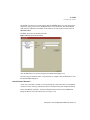
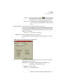
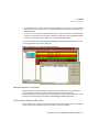
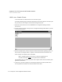
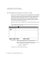
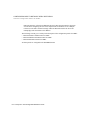
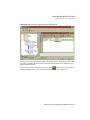
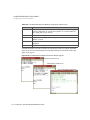
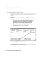
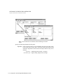
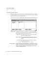
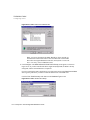
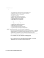
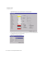
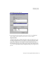
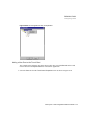
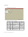
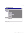
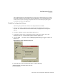
Note: The screen representations in this chapter reflect the FactoryLink
6.6 Configuration Manager user interface, rather than the Configuration
Explorer view that comes with FactoryLink 7.0. The information to be
entered is the same, whether you use Configuration Manager (6.6) or the
form or grid view of Configuration Explorer (7.0).
16 / FactoryLink / Task Configuration Reference Guide
•
•
•
•
Chapter 1
Alarms
The alarms task is used to define alarms and monitor them throughout an alarm cycle until the
tag value no longer meets the alarm criteria.
Alarming interacts with the Historian task to write alarm records to a database. The alarm data
is logged to the relational database and/or to a file in a table or text format. The FactoryLink
Distributed Alarm Logger performs logging as the status of the alarm changes: as the alarm
occurs, when the alarm is acknowledged, or after an alarm has returned to the normal status.
At run time, the alarm task provides the operator the ability to view and manage the alarms
which have met the established alarm criteria in the real-time database.
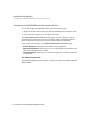
Alarming offers several useful features:
• Custom configuration of the criteria that generates an alarm
• Definition of the requirement of an acknowledgment
• Deadband provision in the alarm criteria
• Saving alarm records to a relational-database or a flat file to preserve the time of alarm and
alarm message for historical purposes
• Viewing alarms from multiple servers
• Customized AlarmViewer to manage alarms as they occur, return to a normal status, and are
acknowledged.
• Enabling a run-time visual accounting of the alarm and the associated factory process using
animations to represent factory subsystems.
• Browsing alarm records previously logged to a database.
This chapter contains five sections:
• “Alarming Operating Principles”
• “Configuring Alarms”
• “Run-Time Alarming”
• “Properties, Methods, and Events”
• “Error Messages”
FactoryLink / Task Configuration Reference Guide / 17
ALARMS
Alarming Operating Principles
A LARMING O PERATING P RINCIPLES
Data collected by FactoryLink is stored in a tag in the real-time database. Each time data is
collected, the value stored in the real-time database for the tag is overwritten by the new data.
Using the tables provided to configure the Distributed Alarm Logger task, you can establish
the criteria that generates an alarm for any defined data element in the real-time database. If the
value for the element meets the criteria established for alarming, an alarm message is displayed
on the AlarmViewer for the FactoryLink operator. The operator monitors the alarm instances
throughout the alarm cycle in the AlarmViewer until the alarm tag values no longer meet the
alarm criteria.
The alarm criteria can be configured to require an acknowledgment from the operator. The
acknowledgment ensures the operator knows the alarm has been generated because the alarm
does not clear from the viewer until it is acknowledged.
If you want to preserve the times and occurrences of alarms, configure the Distributed Alarm
Logger task to send the alarm data to a disk-based relational database using an Historian task.
You can configure the Distributed Alarm Logger task to distribute the alarm messages across a
network if you want the alarms to be viewed on more than one workstation. If the alarms are
being logged and acknowledged, the node names where they were acknowledged are included
in the alarm data sent to the relational database.
This section introduces the operational concepts you use to configure the Distributed Alarm
Logger task operations:
• Alarm logging methodology
• Establishing the alarm criteria
• Alarm status
• Alarm categories
• Parent/child relationship
• Hide alarms
• Locally redefined unique alarm ids
• Alarm persistence
• Alarm distribution
• Alarm logging
• Logbook
For information on procedures to configure the alarm logger task, refer to Define Alarm
Records on page 58, in the this chapter.
18 / FactoryLink / Task Configuration Reference Guide
ALARMS
Alarming Operating Principles
Alarm Logging Methodology
These steps describe how memory-resident real-time data is monitored for alarm conditions
and logged to a disk-based relational database:
1 The real-time database receives and stores data from various sources, such as a remote device,
user input, or computation results from a FactoryLink task.
2 The Distributed Alarm Logger task reads and compares the values of the data elements stored
in the real-time database with criteria defined in tables. These tables contain the configuration
information for the Distributed Alarm Logger task.
3 When the value of the data element meets the criteria for an alarm, the Distributed Alarm
Logger task sends the alarm to the alarm server for display on the AlarmViewer.
4 Each time the data value changes, the Distributed Alarm Logger task evaluates the element. If
the status has changed, the AlarmViewer is updated.
5 When the value of the data element no longer meets the criteria for an alarm, the Distributed
Alarm Logger task removes the alarm from the active alarm list. The alarm is cleared from the
AlarmViewer. However, if the alarm has been configured to require an acknowledgement from
the operator, a status change to the alarm message occurs instead. When acknowledged the
alarm is cleared from the list.
6 If the alarms are being logged to a relational database, the Distributed Alarm Logger task sends
the alarm data to the relational database using a Historian task each time there is a change in
the status of the alarm.
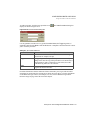
Establishing the Alarm Criteria
When the value of a data element meets the criteria to trigger an alarm, an alarm message is
generated on the AlarmViewer for the FactoryLink operator. An example of this is the
alarming of the pressure in a fuel tank. A safe pressure is established as a reading of 0-1000:
• If the pressure exceeds 900, a HI alarm is generated to indicate the pending danger.
• If the pressure exceeds 950 which could be critical, the alarm generates a HIHI alarm.
In both cases, the tag condition is greater than (>) but each alarm is different. As the pressure
changes, the display is updated to reflect the new readings and messages. When the pressure
drops to 800, the danger passes and the alarms are no longer active.
There are three components that the data element value must be checked against to establish
this alarm:
• Limit—The limit is the value the condition is checked against. The example establishes the
limit as 900.
FactoryLink / Task Configuration Reference Guide / 19
ALARMS
Alarming Operating Principles
• Condition—The condition that triggers the alarm. In the example, the condition is greater
than.
• Deadband—The deadband is a range above or below the limit. The alarm stays active in this
range. The example uses a deadband of 100 (900-100 = 800).
The Limit and the Deadband can both be set with a constant value or the value from another
tag. The following valid condition settings generate alarms:
ON
An alarm is triggered when the value of the element referenced is ON (1).
OFF
An alarm is triggered when the value of the element referenced is OFF (0).
TGL
An alarm is triggered when the value of the element referenced changes
from ON (1) to OFF (0) and then back to ON (1) or from OFF (0) to ON (1)
and then returned to OFF (0).
HI, GT, HIHI or >
An alarm is triggered when the value of an analog or floating-point element
is greater than the value specified by the Limit.
LO, LT, LOLO or <
An alarm is triggered when the value of an analog or floating-point element
is less than the value specified by the Limit.
GE or >=
An alarm is triggered when the value of an analog or floating-point element
is greater than or equal to the value specified by the Limit.
LE or <=
An alarm is triggered when the value of an analog or floating-point element
is less than or equal to the value specified by the Limit.
EQ or =
An alarm is triggered when the value of an analog or floating-point element
is equal to the value specified by the Limit.
NE or <>
An alarm is triggered when the value of an analog or floating-point element
is not equal to the value specified by the Limit.
If a TGL condition is established, the alarm vanishes as soon as it is detected because it
immediately returns to normal. If the alarm is configured to require operator
acknowledgement, the alarm is visible until it is acknowledged and then clears from the
display. Alarms are logged to a relational database regardless of whether the alarm
configuration requires acknowledgement.
20 / FactoryLink / Task Configuration Reference Guide
ALARMS
Alarming Operating Principles
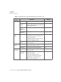
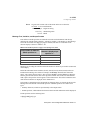
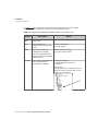
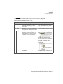
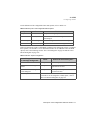
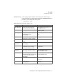
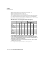
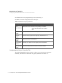
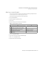
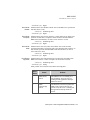
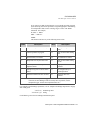
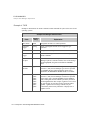
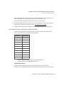
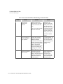
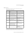
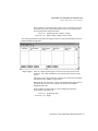
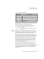
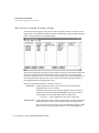
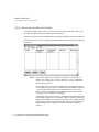
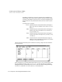
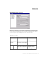
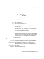
Not all conditions are valid for all tag types. For the conditions supported by each tag type,
refer to Table 1-1.
Table 1-1 Supported Conditions for Each Tag Type
Condition
Digital
Analog
Longana
X
X
X
LOLO LO LT <
X
X
X
HIHI
HI GT >
X
X
X
LE < =
X
X
X
GE > =
X
X
X
X
X
X
X
X
X
X
X
ON
X
OFF
X
TGL
X
EQ =
NE < >
X
Float
Message
Mailbox
X
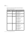
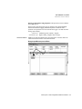
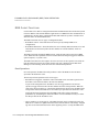
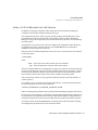
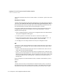
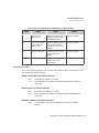
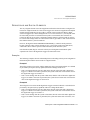
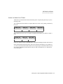
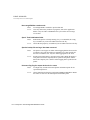
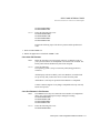
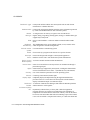
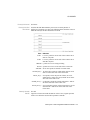
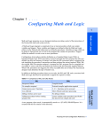
Digital Tags
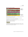
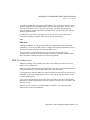
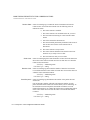
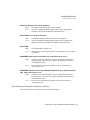
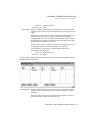
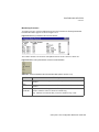
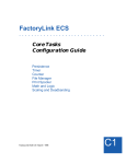
The behavior of a digital alarm with specified limits by tag type is illustrated in Figure 1-1. The
diagram represents an alarm status of active and normal based on a value, a limit, and
deadband range.
FactoryLink / Task Configuration Reference Guide / 21
ALARMS
Alarming Operating Principles
Figure 1-1 Digital Alarm Cycle
FF
N
Active
Active
Normal
Normal
1
1
TAG
0
TAG
0
Time
Time
TGL
Note: A TGL condition is
unique because an alarm
immediately returns to the normal
status. It is not visible to you if
you do not configure the alarm to
require acknowledgment.
Active
Normal
1
TAG
0
Time
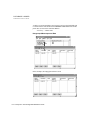
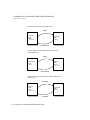
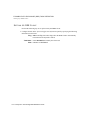
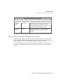
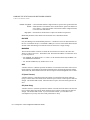
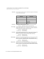
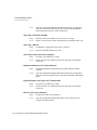
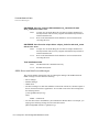
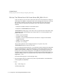
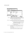
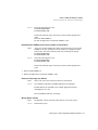
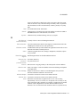
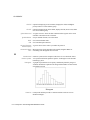
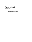
Analog, Long Analog, and Float Tags
The principle of operations are identical when operating on analog, longana or float tag types.
The smallest unit detected is dependent on the type.
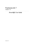
The behavior of an analog, longana or float tag types with specified limits is illustrated in
Figure 1-1. The diagrams represent an alarm status of active and normal based on the value,
limit, and deadband range.
All examples are based on the following parameters:
• Limit:
5
• Deadband: 2
22 / FactoryLink / Task Configuration Reference Guide
ALARMS
Alarming Operating Principles
Figure 1-1 Analog and Float Alarm Cycles
LT
GT
>
<
Active
Active
LE Normal
GE Normal
<=
>=
7
7
5
5
TAG
TAG
3
3
Time
Time
NE
EQ
=
<>
Active
Active
Normal
Normal
7
7
5
5
TAG
TAG
3
3
Time
Time
Message Tags
When there is a change in the value of a Message tag the value is checked to be equal or not
equal to the entire message defined as part of the alarm criteria.
Alarm Status
Every time the value of an alarm element is changed, the new value is evaluated against the
alarm criteria:
• If the criteria are not met for an alarm, the value is considered in a normal status.
• If the criteria are met, a new alarm is added to the active alarm list and the alarm is in an
active status.
• If the alarm is already active and the value no longer meets the criteria, it returns to the
normal status.
• If the criteria are met and the alarm does not require an acknowledgment, it is removed
immediately from the list.
FactoryLink / Task Configuration Reference Guide / 23
ALARMS
Alarming Operating Principles
• If the criteria are met and the alarm required an acknowledgment and has been
acknowledged, it is removed from the list.
• If the criteria are met and the alarm requires an acknowledgment and has not been
acknowledged, it remains on the list until acknowledged and then is removed.
• The initialization of an alarm causes the Distributed Alarm Logger task to log the message
to the relational database, providing the configuration is set to log alarms.
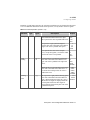
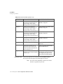
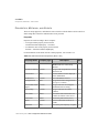
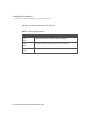
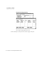
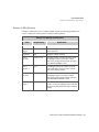
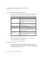
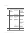
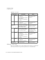
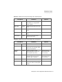
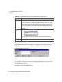
Interpretation of the status code values is dependent upon the tag type defined in the Status
field of the Alarm Definition Information table. For additional information about the Status
field, refer to the section Define Alarm Records on page 58. Table 1-2 shows the values for an
analog and a digital tag type.
Table 1-2 Run Time Status Values
Status
Initial
Definition
3
0
Acknowledged* The alarm status which occurs when the operator
performs the acknowledgement function on an active
alarm. The alarm remains listed on the AlarmViewer
after acknowledgement until the alarm criteria returns
to normal.
2
1
Normal and not The criteria that triggered the alarm has been removed
acknowledged but the operator has not performed the
acknowledgement function.
1
0
Idle
0
0
*
An active alarm; an alarm that has its alarm criteria
met. The alarm remains in this status until there is
operator action.
Analog Digital
Tag
Tag
There is presently no criteria to trigger this alarm and
the alarm does not need acknowledgment from prior
alarm condition.
Only alarms configured to require operator acknowledgement in the Alarm Group Table
will remain listed on the AlarmViewer after a return to normal status occurs.
The Distributed Alarm Logger task maintains running counts of the number of alarms in the
active queue which are predefined in the Alarm Group Control table. For more information,
refer to Set up General Alarm Counters on page 71 in this chapter.
24 / FactoryLink / Task Configuration Reference Guide
ALARMS
Alarming Operating Principles
Alarm Categories
Categorizing alarms facilitates administration and analysis. Three methods are provided to
show related alarms:
• Group Name—The group name is assigned to a class of alarms. Group names can be
identifiers of the severity of the alarm, represent similar types such as pressure gauges, or
indicate a combination of any other characteristics.
• Area—The area is assigned to each alarm individually. More than one alarm can reside in an
area and alarms from different groups can also reside together. An area can reflect a physical
location such as the boiler room or an area of responsibility such as maintenance.
• Priority—The priority is a number hierarchy assigned to each individual alarm. Use a
number between 1 (lowest) and 9999 (highest) to set priority. Multiple alarms can be
assigned the same priority number and multiple groups and areas can have common priority
numbers within them.
At least one Group Name must be established to define any individual alarms: All alarms must
belong a to a group. The use of areas and priorities is optional. Categories enable filtering and
sorting of alarms on the AlarmViewer.
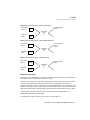
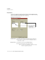
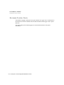
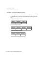
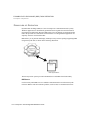
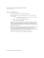
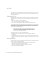
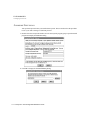
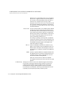
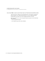
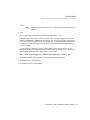
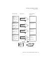
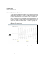
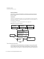
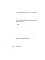
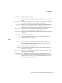
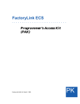
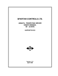
Parent/Child Relationship
The conditions which cause the generation of one alarm may cause another alarm to be
generated. When these relationships exist, you generally do not want to display the additional
alarms. An example: if the closing of a valve that feeds four different pipelines generates an
alarm, it is a reasonable assumption that the lack of flow in each pipe would generate an alarm
based on the value of the flowmeter element as shown in Figure 1-2. These resulting alarms
would not be important because you already know the flow has been cut off and why. This
relationship between the alarms is identified as a parent/child relationship. In this example the
main valve is the parent alarm of each of the flow alarms. The resulting child alarms are not
displayed or counted as active alarms because they are a result of the parent alarm.
Figure 1-2 Parent/Child Alarm Relationship
Child Alarm
Child Alarm
Parent Alarm
Child Alarm
Child Alarm
However, if the main valve is open and one of the individual pipeline flowmeters registers an
alarm, you would want to be advised. In this case the child is not dependent on the parent
FactoryLink / Task Configuration Reference Guide / 25
ALARMS
Alarming Operating Principles
because the child alarm initiated on its own. This alarm is displayed and counts as an active
alarm.
Each alarm can have multiple parent/child relationships. Alarms defined in a remote group can
never act as a child alarm. A parent alarm must have a defined Unique Alarm ID to create the
child alarms on the local node.
TGL type is not a recommended type for a parent alarm. When a TGL alarm is initiated, it
becomes ACTIVE and immediately returns to NORMAL. Because it never stays in the
ACTIVE status, using a TGL alarm as a parent would result in the child alarm never being
hidden.
Each alarm is evaluated by the Distributed Alarm Logger task and compared to its parent/child
relationship prior to displaying.
• If the alarm is a parent, it is displayed.
• If the alarm is a child and the parent status is not active, the child is displayed.
• If the alarm is a child and the parent status is active, the child alarm is disregarded or
displayed based on delay criteria you establish in the relationship.
Within the parent/child relationship two kinds of delays can be specified:
• Child alarm delay
• Child recovery delay
These delays specify the time allowed between the generation or clearing of a parent alarm and
the activation of a child alarm unrelated to the parent. For information on how to configure
these alarms, refer to Define Parent-Child Relationships on page 66 in this chapter.
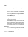
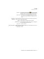
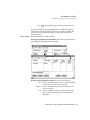
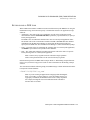
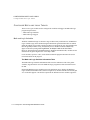
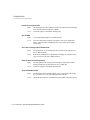
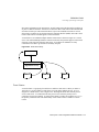
Child Alarm Delay
The length of time a child alarm is suppressed after a parent alarm is triggered is the child
alarm delay.
The conditions that cause both the parent and child alarms to generate must return to normal to
allow the alarm statuses to return to normal. When both have returned to normal, the
parent/child relationship is reestablished. At the next invocation of the parent, the timer is
started again to inhibit the display of the child alarm for the child alarm delay period. These
concepts are shown in Figure 1-3, Figure 1-4, and Figure 1-5.
26 / FactoryLink / Task Configuration Reference Guide
ALARMS
Alarming Operating Principles
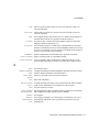
Figure 1-3 Child Alarm Delay - Child is Suppressed
Alarms Displayed
Parent 1
Parent Alarm
10:00
Parent 1
Child Alarm
Child 1
Child Alarm
Delay
:15
10:10
Figure 1-4 Child Alarm Delay - Child is Not Suppressed
Parent Alarm
Parent 1
Child Alarm
Child 1
Alarms Displayed
Parent 1
Child 1
10:00
Child Alarm
Delay
:15
10:17
Figure 1-5 Child Alarm Delay - Child Alarm Only
Parent Alarm
Parent 1
Child Alarm
Child 1
No
Alarm
Alarms Displayed
Child 1
Child Alarm
Delay
:15
10:15
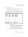
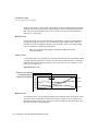
Child Recovery Delay
The length of time a child alarm is provided to return to normal status after a parent alarm has
been return to normal status is the child recovery delay.
In the previous example, the main valve causing the generation of the parent alarm was shut
off. This generated the four pipeline alarms but they are disregarded because they are
redundant. If the main valve is now turned on, the flow should return to all four pipelines. The
child recovery delay provides sufficient time for a child alarm status to return to normal. If the
child status cannot return to normal in this time period then the child alarm generates an alarm.
After the child status has returned to normal, and the parent has a normal status, the
parent/child relationship is reestablished.
For illustrations of these concepts, refer to Figure 1-6 and Figure 1-7.
FactoryLink / Task Configuration Reference Guide / 27
ALARMS
Alarming Operating Principles
Figure 1-6 Child Recovery Delay - Child Recovers
Parent Alarm
Parent 1
Child Alarm
Child 1
Return to
Normal
10:00
Child
Recovery
:05
Alarms
Displayed: none
10:01
10:04
Suppressed
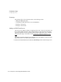
Figure 1-7 Child Recovery Delay - Child Alarms
Parent Alarm
Parent 1
Child Alarm
Child 1
Return to
Normal
10:00
Child
Recovery
:05
Suppressed
10:01
Alarms
Displayed:
Child 1
alarmed
at 10:06
10:15
Hide Alarms
Alarm hiding is done when you do not need to manage a particular set of alarms. Alarm hiding
is used in the following common situations:
• Equipment maintenance
• Redundant systems
• Station functionality
• Bad sensor
Alarm hiding should not be confused with filters used with the AlarmViewer. Alarm hiding
tells the Distributed Alarm Logger task to disregard the AlarmViewer display associated with a
particular set of alarms. Alarm filtering selects specified alarms for viewing and suppresses
other alarms from the AlarmViewer. However, the alarms are still being logged and tracked.
Filtering is more common on multiuser or distributed systems. In these architectures, all users
have the ability to monitor all alarms. However, certain operators may be responsible for a
subset of these alarms. Filters enable operators to view only alarms they are responsible for on
the AlarmViewer.
If an alarm is hidden it does not act as a parent in parent/child relationships. To avoid potential
problems when the parent alarm is hidden, child alarms also must be hidden. For more
information about how to configure alarm hiding, refer to Set up Alarm Groups on page 49.
28 / FactoryLink / Task Configuration Reference Guide
ALARMS
Alarming Operating Principles
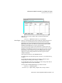
Global Hide Tag
The Global Hide tag is used most frequently in redundant systems. In redundant systems, one
node is the master and all alarms are active for this node (Global Hide tag = 0). The slave node
or standby node has the Global Hide tag = 1.
Group Hide Tag
The Group Hide tag is used to hide equipment maintenance alarms. The developer must ensure
that alarms are grouped by machine, so when a maintenance cycle begins, those alarms can be
hidden.
Note: In addition to the two existing mask settings—Hide (which hides
alarm from the AlarmViewer and the output alarm database) and Show
(which shows alarms on the AlarmViewer and allows writing to the alarm
database), a new setting called Event has been added, which hides alarm
from the AlarmViewer, but shows it in the alarm database.
The Group Hide tags are also used to define station functionality. This is a special case because
a node may have multiple functional requirements. For example, a node may function as a
simple operator station for only one piece of equipment one day. The next day the same node
may be the supervisor's station for all of the equipment. Groups are hidden based on the node
functionality.
Individual Hide Tag
In some systems, individual alarms may need to be hidden to silence an alarm because of a
malfunctioning sensor. When the sensor is repaired, the alarm needs to be monitored again.
Remote Group
There is no hiding function for alarms received from remote groups. Alarms should be hidden
at the server node. If you do not want to view the alarms, create a filter in the AlarmViewer so
the alarms do not show.
Event Alarms
Event alarms are any alarms that are logged to a database but are not processed for viewing and
acknowledgement. This provides the archival of the alarm condition without operator required
processing. To configure an event alarm, use the Group Hide Tag or the Alarm Hide tag.
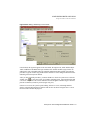
Locally Redefined Unique Alarm IDs
For networked systems, if a local Unique Alarm ID definition can be created and it matches a
remote Unique Alarm ID the alarm appears as if it is a local alarm. The Distributed Alarm
FactoryLink / Task Configuration Reference Guide / 29
ALARMS
Alarming Operating Principles
Logger task must be running on the remote node. In addition to reporting alarms as if they
were local alarms this configuration provides the message text from the remote system to be
displayed on the AlarmViewer.
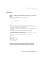
Alarm Persistence
Alarm persistence is the storing of current information about the status of active alarms and the
child alarms at user-defined intervals. At startup the information is read preserving important
information, for example, initial time and acknowledgment information.
Alarm persistence is activated by placing a -w on the program arguments field of Distributed
Alarm Logger task line in the SHARED domain and by configuring and running the SHARED
domain persistence task with a trigger in the Timed Save Trigger field, which causes the
system to save the alarm persistence information each time the persistence trigger is set. The
system then saves the Distributed Alarm Logger task information to the files:
• {FLAPP}/{FLNAME}/shared/al_log.prs
• {FLAPP}/{FLNAME}/shared/al_log.bak
If the *.prs file is not readable at startup, the *.bak file is read.
The al_log.prs file is updated at the time the Distributed Alarm Logger task is shut down, on a
Persistence Timed Trigger change. The al_log.bak file is updated on a Persistence Backup
Trigger change. For more information about the persistence function, refer to the persistence
section of the FactoryLink 6.6 Configuration Guide.
Upon restart of the Distributed Alarm Logger task, the al_log.prs or al_log.bak file is read into
memory, and all alarms are checked for validity.
The active alarms are stored using their Unique Alarm ID number. If you have not defined a
Unique Alarm ID in the alarm definition, one is defined at startup. If the configuration does not
change, all alarms receive the same Unique Alarm ID each time at startup. If the configuration
changes, however, each Unique Alarm ID could be altered, and the Distributed Alarm Logger
task could potentially load persistence information for incorrect alarms or not load persistence
information. For more information about alarm definition, refer to the section Define Alarms
on page 57.
Alarm Distribution
Alarms can be distributed over the network using the FactoryLink Local Area Network. Each
node can share one or more groups of alarms with other nodes. The alarm is originated on the
node it is defined on and is seen and acknowledged from other nodes that have been configured
to receive information on that particular alarm. When the alarm is acknowledged, either at the
source or at the remote, the source node accepts the acknowledgment and updates the new
30 / FactoryLink / Task Configuration Reference Guide
ALARMS
Alarming Operating Principles
alarm status. All nodes receiving information on the alarm are updated. For additional
information on this topic, refer to the FactoryLink 6.6 Configuration Guide.
Alarm Logging
If you want to preserve the time of alarm, alarm data, and the node that acknowledged the
alarm, you can configure Distributed Alarm Logger task to read data from the elements in the
real-time database and send the data to a disk-based relational database or to a text file. Data
logged to a relational database is then available for browsing through the FactoryLink
Database Browser.
The Distributed Alarm Logger task logs data to a relational database using the same
methodology as the FactoryLink Database Logger. The data is logged in a table format using
an Historian task. Alarm instances are logged at a status change: as the alarm occurs, when the
alarm is acknowledged, or an alarm returns to the normal status. The tables for alarm logging
output and their associated schemas have already been defined for the Distributed Alarm
Logger task. For more information refer the section Set up Database Archive Requirements
on page 67 in this chapter that defines the fields of the Alarm Archive Control table to enable
alarm database logging.
If a remote group has logging turned on but no database information is defined on the client
node, no information is logged. This condition does not result in the display of an error
message.
When a remote node shuts down and restarts or reconnects after a communication failure with
the same alarm still active, the logger tries to insert the alarm into the database twice. This
condition results in generating a Duplicate Entry error.
The record length is determined by the size specified in the Message Size field of the Alarm
Archive Control Information table in the Distributed Alarm Logger Setup table.
FactoryLink / Task Configuration Reference Guide / 31
ALARMS
Alarming Operating Principles
For the schema layout used to build the alarm entry table, refer to Table 1-3 and Table 1-4.
Table 1-3 Alarm Entry Table Schema
Column
Type
Array
Description
SEQ
NUMBER
11
Sequence Number of the alarm
AID
NUMBER
11
Alarm ID number
NAME
CHAR
48
Alarm TAG name
GRP
CHAR
16
Group alarm belongs to
AREA
CHAR
16
Area alarm belongs to
PRIO
NUMBER
6
Priority of the alarm
ITIME
CHAR
30
Initial Time (yearmodyhrmisc.mse)
ATIME
CHAR
30
Acknowledge Time (yearmodyhrmisc)
NTIME
CHAR
30
Normal Time (yearmodyhrmisc)
DUR
NUMBER
11
Alarm Duration in seconds
MSG
CHAR
162
Alarm Message
VAR1
CHAR
44
Variable 1 at Initial Status
VAR2
CHAR
44
Variable 2 at Initial Status
VAR3
CHAR
44
Variable 3 at Initial Status
VAR4
CHAR
44
Variable 4 at Initial Status
OPR
CHAR
8
Name of operator who acknowledged
the alarm
Table 1-4 Alarm Entry Column Schema
Index
1
Unique
YES
Column list
SEQ + ITIME.
Logbook
Prior to the FactoryLink 7.0 software release, the Distributed Alarm Logger task had provided
a logbook entry capability during run time that allowed an operator to annotate an alarm
record. These entries were saved in the relational database or a file when the alarms were
logged and were also distributed along the network if the alarms were distributed.
The logbook provided the addition of notes to the alarm to document why an alarm occurred,
how it was corrected, or what is being done to correct it. If the alarms were being distributed,
all operators on the network could add logbook entries to the alarm.
32 / FactoryLink / Task Configuration Reference Guide
ALARMS
Alarming Operating Principles
Logbook entries can be added to the alarm records but the legacy alarm viewer must be used.
The legacy alarm viewer is launched at FactoryLink startup. For more information about
logbook entries, refer to the FactoryLink 6.6 Configuration Guide.
Entries to the logbook are indicated by an asterisk in the Logbook field when viewed on the
FactoryLink 7.0 Alarm Control Viewer. The logbook data is viewable using the FactoryLink
Database Browser. For more information about browsing alarms, refer to the section Browsing
Archived Alarms on page 127 in this chapter.
FactoryLink / Task Configuration Reference Guide / 33
ALARMS
Configuring Alarms
C ONFIGURING A LARMS
This section explains how to locate the alarm tables, the definitions of the table fields, and the
design of the AlarmViewer that enables managing the active alarms in the run-time mode:
• Navigate Configuration Explorer
• Configure Alarms Sequence
• AlarmViewer Design
Many of the examples in this section are from the StarterApp (starter application) that is
supplied with every installation. The StarterApp provides tables with preconfigured data to
illustrate proper configuration of the fields.
Navigate Configuration Explorer
The FactoryLink Server and the FactoryLink Application directory (FLAPP) must be
established before configuring the alarm tables. This is accomplished using the Configuration
Explorer application. For a complete description on how to configure an application and the
Configuration Explorer features and options, refer to the Configuration Explorer User Guide.
To launch Configuration Explorer: click the Configuration Explorer icon displayed on the
desktop. Expand the Enterprise View item. Expand FactoryLink Servers. Expand
MyFactoryLink Servers to display the defined applications. Expand the MyFactoryLink
Servers as shown in Figure 1-8.
34 / FactoryLink / Task Configuration Reference Guide
ALARMS
Configuring Alarms
Figure 1-8 FLAPP Contents in Configuration Explorer
Double-clicking the
application name
displays the FLAPP
contents.
View Alarm Tables
You configure alarm tables from the application tree. All of the configuration tables are
available to you in their respective folders.
To view the alarm tables, expand the items in the application tree.The application tree provides
selection and configuration of all FactoryLink tables and tasks. Tables are identified in the tree
by the FactoryLink icon on the folder icon. Double-click the table name in the tree to open the
tables in the workspace.
FactoryLink / Task Configuration Reference Guide / 35
ALARMS
Configuring Alarms
Figure 1-9 Location of Alarm Tables in Configuration Explorer
Note: All configuration for FactoryLink 7.0 is in the SHARED domain.
USER domain indicators are provided for upgrade from older
FactoryLink versions.
The default view for a table is the Grid View as shown in Figure 1-10. The Form view is the
default for single record items. Double-click a table or single record item and the respective
view displays in the workspace as shown in Figure 1-11.
36 / FactoryLink / Task Configuration Reference Guide
ALARMS
Configuring Alarms
Figure 1-10 Configuration Explorer Grid View
FactoryLink / Task Configuration Reference Guide / 37
ALARMS
Configuring Alarms
Figure 1-11 Configuration Explorer Form View
Methods to Create or Modify Records
The Configuration Explorer application provides the configuration of alarm records using
three different methods:
• Field Level Editing: Recommended for simple, single record editing
• Record Generation Box: Definition of one or many records through the use of the Record
Generation dialog box.
• Application Objects: Definition of highly reusable, repeatable creation of record instances
using Application Object templates.
The method used to configure the alarms is dependent on the number of alarms needed and
user preference. For more detailed instructions, refer to the Configuration Explorer User
Guide.
38 / FactoryLink / Task Configuration Reference Guide
ALARMS
Configuring Alarms
Field Level Editing
Field level editing is recommended for very simple changes that cannot be accomplished with
repeatable functions. Records can be duplicated using standard copy and paste functions or
added by using the Form view and the Grid view of the tables.
Each field within the table must be accessed and modified individually using this editing
method. Alarm records are created one at a time. Drop down menus show acceptable selection
values. Tag fields present a drop list of predefined tags if the beginning letters typed match a
predefined tag name.
Record Generation Box
The Record Level Generation Box displays many options available for rapid generation of
records and tables. These options are configurable on a per field basis. There can be any
combination of data origins within the record design:
• Constant values
• Numerical Sequence (simple numbering sequence or array-based)
• Text file input (from an external text file)
• Excel spreadsheet input (from an external EXCEL file)
• Custom Functions (generation of files using output from a VBA-compatible script)
• ODBC (ADO)
Generating records using this method is fast and flexible. However, the process for each
session cannot be saved for later reuse as with Application Objects.
Application Objects
Application Objects provide a new dimension in creating alarm records. Application Objects
create records with the same origins as the Record Generation process using: constants, text
file input, numerical sequencing, Excel spreadsheet lists, custom functions and ODBC.
However, once the Application Object is designed, the process is quickly and instantly
repeatable.
Using Application Objects also has the additional option of prompting the user for keyboard
input. Thus once the Application Object design is complete, the generation of new records can
be an interactive task.
The Application Objects are designed by a dragging items from a configuration objects list or
templates variable list and dropping them into a new alarm design. This eliminates all the
individual repeated steps. For example, an array table, a field constant, a custom message field
prompt, and the input location from an Excel spreadsheet can all be dragged and dropped into
an Application Object design.
FactoryLink / Task Configuration Reference Guide / 39
ALARMS
Configuring Alarms
The interactivity provides conformity of the design for consistency and yet enables individual
custom needs and requirements. One or many alarm instances can be created repeatedly, with
the same design and relationships. For example, different workgroups may require a different
level of viewing tables, or there may be different files used to generate the alarm data on
different servers. The user can be prompted to enter the specific data for that week,
workstation, or viewer level.
The Application Object design process provides testing prior to implementation to ensure
accuracy of design, structure and function.
Configure Alarms Sequence
A suggested sequence for configuration of alarms is the following:
• Verify Alarm Server Functions
• Set up Alarm Groups
• Define Alarms
• Set up Archive Database Requirements
• Set up General Alarm Counters
40 / FactoryLink / Task Configuration Reference Guide
ALARMS
Configuring Alarms
Use Table 1-5 as an overview to navigate through the Configuration Explorer tables and to
configure alarms:. Each function is described in more detail in this chapter.
Table 1-5 Recommended Alarm Configuration Sequence (Sheet 1 of 2)
Step
1
Functions
Description
Verify Alarm Server Functions on
page 42
Verify Alarm Server Task Set up The Alarm Server task and the
on page 42
associated executable alarm server
file are predetermined in the
FactoryLink software.
Verify the Distributed Alarm
Logger Task on page 44
The Distributed Alarm Logger task
name is AL_LOG. It is preconfigured
to initiate at run time.
Verify the Distributed Alarm
Server 7.0 Table on page 47
The mailbox tags to provide
communication between the
Distributed Alarm Logger task and
the Alarm Server are preconfigured.
Verify Polling Trigger Timer
Setup on page 48
The polling trigger tag is preset in the
Polling Trigger Timer Setup table.
The polling interval is set to a default
of 10 seconds in an Interval Timer
table. This may be modified if
necessary.
2
Set up Alarm Groups on page 49
3
Define Alarms on page 57
All tables must be part of a group.
Groups must be established prior to
definition of the member alarms.
Related Alarm
Tables
Distributed Alarm
Server 7.0 Field
Definitions
Interval Timer - Poll
Trigger Tag
Definition Fields
Alarm Group Control
Fields
Define Alarm Records on page
58
Alarm Definitions
Each alarm is a record in the group
table. Single or multiple alarms can be Table Field
Definitions
quickly generated.
Define Parent-Child
Relationships on page 66
Alarms
Optional. If more than one alarm is
generated because of the same event, Relationships Field
Definitions
these alarms may have a sequential
relationship. This relationship can be
configured to include a delay to avoid
redundant or related alarm messages.
FactoryLink / Task Configuration Reference Guide / 41
ALARMS
Configuring Alarms
Table 1-5 Recommended Alarm Configuration Sequence (Sheet 2 of 2)
Step
Functions
Description
Related Alarm
Tables
4
Set up Database Archive
Requirements on page 67
Optional. This table is used to identify Alarm Archive
the files (the schema) for the external Control Fields
or internal database where alarm
information is logged.
5
Set up General Alarm Counters on
page 71
Optional. A table is provided to store
counts of the various alarm statuses
and the alarms maintained by the
Distributed Alarm Logger task.
General Alarm Setup
Control Fields
Verify Alarm Server Functions
The alarm server tasks and functions are preconfigured in the FactoryLink software because
they do not require any specific customization for individual installations. Most of the default
values can be changed as needed.
This section briefly explains the purpose of the functions and how the tables or dialog boxes
are accessed. These functions are explained:
• Verify Alarm Server Task Set up
• Verify the Distributed Alarm Logger Task
• Verify the Distributed Alarm Server 7.0 Table
• Verify Polling Trigger Timer Setup
Verify Alarm Server Task Set up
The Alarm Server task and the associated executable alarm server file are predetermined in the
FactoryLink software as part of the System Configuration Information.
The Alarm Server manages the alarm output using the Alarm Server task. In response to an
alarm condition, the Distributed Alarm Logger task creates a message. The message can be
output to the AlarmViewer through the Alarm Server, one or more databases, a text file or a
printer.
For the location of the Alarm Server task, refer to Figure 1-12. For the default configuration of
the task, refer to Table 1-6.
42 / FactoryLink / Task Configuration Reference Guide
ALARMS
Configuring Alarms
Figure 1-12 Alarm Server Task Dialog Box
Table 1-6 Alarm Server Task (Sheet 1 of 2)
Field
Name
Domain
Definition
For FactoryLink 7.0 users who are not converting
applications from prior versions, SHARED domain is the
only option. For legacy domain requirements, refer to the
FactoryLink 6.6 system documentation.
Task
Task Name
Information
Task
Description
Default
Shared
Predefined name for the task which cannot ALARMSRV
be changed
Optional alphanumeric description
Alarm Server
FactoryLink / Task Configuration Reference Guide / 43
ALARMS
Configuring Alarms
Table 1-6 Alarm Server Task (Sheet 2 of 2)
Field
Name
Task Flags
Definition
Default
Run at Startup
R: Invokes task at FactoryLink startup
Yes
Create Session
Window
S: Provides the process with its own tab
Optional
window. Output prints to the
Configuration Explorer Output window.
Suppress Online O: Suppress online updates for this process Optional
Configuration
Flag String
Value
Task
Options
Task
Executable
Suppress Task
Hibernation
H: Not applicable for alarm functions
Input box
Displays value code of selected Task Flags Yes
F: Foreground Flag. Puts this task in the
foreground at startup
Edit Flags
Directly
If selected, allows user input of string
values to input box.
Not selected
Start Order
Specifies the run-time rank for invoking
the task when FactoryLink is started
1
Start Priority
Operating system processing priority
Executable File The path and name of the file which
executes this task
Program
Arguments
*
Not applicable
201
bin/alarmsvr
The codes which add customization to the None
functions of the task
-L: log error messages to a file *
-L-V#: log error messages with more
information to a file. Verbose level
increases from 1 through 9
Default message file location is: {FLAPP}/{FLNAME}/{FLDOMAIN}/log
Verify the Distributed Alarm Logger Task
The default options for the Distributed Alarm Logger task are preconfigured in the
FactoryLink software. The task name AL_LOG is standard and cannot be changed. Other
options can be modified by the designer.
For the location of the Distributed Alarm Logger task, refer to Figure 1-13. For the default
configuration of the task, refer to Table 1-7.
44 / FactoryLink / Task Configuration Reference Guide
ALARMS
Configuring Alarms
Figure 1-13 Distributed Logger (AL_LOG) Task Dialog Box
Table 1-7 Distributed Alarm Logger Task Dialog Box Fields (Sheet 1 of 2)
Field
Name
Domain
Definition
For FactoryLink 7.0 users who are not converting
applications from prior versions, SHARED domain is the
only option. For legacy domain requirements, refer to the
FactoryLink 6.6 system documentation.
Task
Task Name
Information
Task
Description
Default
Shared
Predefined name for the task which cannot AL_LOG
be changed.
Optional alphanumeric description.
Distributed Alarm
Logger task
FactoryLink / Task Configuration Reference Guide / 45
ALARMS
Configuring Alarms
Table 1-7 Distributed Alarm Logger Task Dialog Box Fields (Sheet 2 of 2)
Field
Name
Task Flags
Definition
Run at Startup R: Invokes task at FactoryLink startup.
Default
Yes
Create Session S: Provides the process with its own tab
Optional
Window
window. Output prints to the Configuration
Explorer Output window.
Suppress
Online
Configuration
O: Suppress online updates for this process. Optional
Suppress Task H: Not applicable for alarm functions.
Hibernation
Flag String
Value
Task
Options
Task
Executable
*
Not applicable
Input box
Displays value code of selected Task Flags. FR
F: Foreground Flag. Puts this task in the
foreground at startup.
A: Suppress printing of return-to-normal
messages for toggle type fields
Edit Flags
Directly
If selected, allows user input of string
values to input box.
Start Order
Specifies the run-time rank for invoking the 2
task when FactoryLink is started.
Start Priority
Operating system processing priority
201
Executable
File
The path and name of the file which
executes this task.
bin/al_log
Program
Arguments
The codes which add customization to the
functions of the task.
-L: log error messages to a file *
-L-V#: log error messages with more
information to a file. Verbose level
increases from 1 through 9
None
Not checked
Default message file location is: {FLAPP}/{FLNAME}/{FLDOMAIN}/log
46 / FactoryLink / Task Configuration Reference Guide
ALARMS
Configuring Alarms
Verify the Distributed Alarm Server 7.0 Table
The Distributed Alarm Server 7.0 table supplies the mailbox and trigger information for the
Alarm Server and the Distributed Alarm Logger tasks to communicate as shown in Figure
1-14.
Figure 1-14 Distributed Alarm Server 7.0 Table
These tags are required for communication. The time interval for the poll trigger tag can be
modified using the Interval Timer table. For most fields, Default refers to a preconfigured
value that appears when the application is created. The alarm server table tags are:
Send Mailbox
Storage of communications retrieved by the Distributed Alarm Logger task
Default Entry: ALARMSRV_SNDMBX
Valid Data Type: Alphanumeric
Valid Entry: Mailbox
1 to 16 characters
FactoryLink / Task Configuration Reference Guide / 47
ALARMS
Configuring Alarms
Receive Mailbox
Storage of communications from the Distributed Alarm Logger task
Default Entry: ALARMSRV_RCVMBX
Valid Data Type: Alphanumeric
Valid Entry: Mailbox
1 to 16 characters
Poll Trigger:
Polling frequency of the communications between the Alarms Server and
the Distributed Alarm Logger
Default Entry: ALARMSRV_POLL
Valid Data Type: Digital
Valid Entry: Standard tag name
Verify Polling Trigger Timer Setup
The polling frequency for the Distributed Alarms Server is preconfigured in the Interval Timer
Information table as shown in Figure 1-15). For most fields, Default refers to a preconfigured
value that appears when the application is created.
Figure 1-15 Interval Timer Information Table
48 / FactoryLink / Task Configuration Reference Guide
ALARMS
Configuring Alarms
Tag Name
Name of tag to maintain the trigger value for the timing sequence to occur
Valid Data Type: Digital
Valid Entry: Standard tag name
Default: ALARMSRV_POLL
Hours
Time interval for a trigger segmented in hours
Valid Data Type: Analog
Valid Entry: 1 through 99
Default: None
Minutes
Time interval for a trigger segmented in minutes
Valid Data Type: Analog
Valid Entry: 1 through 99
Default: None
Seconds
Time interval for a trigger segmented in seconds
Valid Data Type: Analog
Valid Entry: 1 through 99
Default: 3
10ths
Time interval for a trigger segmented in tenths of seconds
Valid Data Type: Analog
Valid Entry: 1 through 99
Default: None
Set up Alarm Groups
The Alarm Group Control table is used to define the properties assigned to each alarm group.
There must be at least one group defined for your installation. All alarms must be a member of
a group.
Group functions defined using this table include the following information:
• Group name and group message text
• Group counters for composite status and number of active alarms in the group
• Groups that need to be acknowledged by an operator
• Group hide selection to prohibit alarm messaging in startup or non-error conditions and for
event logging.
• Printing to text files or print to database options
For the location of the Alarm Group Control table, refer to Figure 1-16.
FactoryLink / Task Configuration Reference Guide / 49
ALARMS
Configuring Alarms
Figure 1-16 Alarm Group Control Table
In the FactoryLink 7.0 Version release, color and sound information in the Alarm Group
control table does not transfer to the Client Builder AlarmViewer. These features are
individually configurable in the Client Builder application. See Table 1-8 for a comprehensive
list.
Table 1-8 Alarm Group Control Table Valid Fields for Version 7.0 (Sheet 1 of 2)
Field Name
Field Data Passed to Client
Builder AlarmViewer
Group Name
Yes
Group Text
Yes
Group Composite Status Tag
No
Group Number Active Tag
No
Ack
Yes
Aud
No
Alarm Stat Print Dev
No
LOG
No
Log Method Tag
No
Initial FG Clr
No
50 / FactoryLink / Task Configuration Reference Guide
ALARMS
Configuring Alarms
Table 1-8 Alarm Group Control Table Valid Fields for Version 7.0 (Sheet 2 of 2)
Field Name
Field Data Passed to Client
Builder AlarmViewer
Initial BG Color
No
Initial Blink
No
ACK FG Color
No
ACK BG Color
No
ACK Blink
No
Normal FG Color
No
Normal BG Color
No
Normal Blink
No
Group Hide Tag
No
There are three groups preconfigured for default purposes: WARNING, CRITICAL, SYSTEM.
These can be used or deleted as required. For most fields, Default refers to a preconfigured
value that appears when the application is created.
Group Name:
A string to identify the Alarm Group (required field).
Valid Data Type: Uppercase alphanumeric string
Valid Entry: 1 to 16 characters
Default: Blank
Group Text:
Group message text that can appear with the output of each individual alarm
message
An optional field but important to assist determining the alarm group when
the message is output to a database or to the AlarmViewer.
Valid Data Type: Alphanumeric string
Valid Entry: 1 to 40 characters
Default: Blank
Group Composite
Status Tag:
Tag that stores the code number representing the current status of all alarms
in a particular alarm group
Valid Data Type: Analog
Valid Entry: Standard Tag name
0: (IDLE) No alarms in the group are active.
1: (NORMAL)At least one alarm in the alarm group is
unacknowledged and has returned to normal.
2: (ACK)At least one alarm in the alarm group is active
FactoryLink / Task Configuration Reference Guide / 51
ALARMS
Configuring Alarms
and has been acknowledged.
3: (ACTIVE)At least one alarm in the alarm group is
active and unacknowledged.
11: (NORM/ACK)At least one alarm in the alarm group
is unacknowledged and has returned to normal and one
other alarm is active and acknowledged.
Default: Blank
Group Number
Active Tag:
Field that contains a tag that stores the number of active alarms in this
group
Valid Data Type: Analog
Valid Entry: Standard tag name
1 through the maximum number of tags allowed.
Default: Blank
ACK:
Indicates if the alarms belonging to this group need to be acknowledged
Note: If this field is set to YES or RST, the Unack Alarms Count Tag
field in the General Alarm Setup Control table counts the
unacknowledged alarms. Ensure that the Unack Alarms Count Tag field
contains a tag (a default tag name is provided with FactoryLink.) For more
information, refer to Set up General Alarm Counters on page 71 in this
chapter.
Valid Data Type: Key
Valid Entry: NO: No acknowledgment required. The alarm
disappears from the active list when it returns to normal.
YES: The alarm must be acknowledged.
RST: The alarm must be acknowledged but not until the
alarm has returned to normal. This field can be used to
reset alarms in the PLC or controller in conjunction with
the alarm status.
Default: NO
AUD:
Determines if the alarms belonging to this group produce an audible signal
when the alarm status is active
Note: If this field is set to YES, the alarms in this group are included in
the count maintained by the Audible Alarms Count Tag in the General
Alarm Setup Control table.For more information, refer to Set up General
Alarm Counters on page 71 in this chapter.
Valid Data Type: Key
Valid Entry: Not applicable for FactoryLink version 7.0
Default: NO
52 / FactoryLink / Task Configuration Reference Guide
ALARMS
Configuring Alarms
Alarm Stat Print
Dev:
Print device number that corresponds to the line number of the printer
device defined in the Print Spooler Information table (see Figure 1-17).
Figure 1-17 Print Spooler Information Table
The line number represents
the device or print file.
Put this number in the
Alarm Stat Print Dev field
If configured, alarm records are printed when generated or when there is a
change in the alarm status (see Message Text, Variables, and Output
Formats on page 63 in this chapter).
Valid Data Type: Numeric
Valid Entry: 0: Function disabled
Any other number is the print device number.
Default: Blank, no printing is enabled.
LOG:
Specifies if group alarms are logged to a database or to a flat file
Valid Data Type: Key
Valid Entry: NO or N: No logging.
YES or Y: When an alarm is changes status, it is logged
to a relational database
FILE or F: When an alarm changes status, it is logged to
a text or flat file.
Default: NO
FactoryLink / Task Configuration Reference Guide / 53
ALARMS
Configuring Alarms
Log Method Tag:
Tag that enables a run-time change of the logging method.
When set to the value 1, the alarm records are written to a database unless
the database cannot be accessed. If this occurs, the alarm records are
automatically written to a file as specified in the Device field of the Print
Spooler Information table as shown in Figure 1-17. To return to database
logging, the operator must manually reset this field to a value of 1. A
run-time change is initiated using an animated graphic in the Client Builder
program or using the Run-Time Monitor (RTMON) utility. For more
information about the RTMON utility, refer to the Utilities chapter in this
guide.
See Set up Database Archive Requirements on page 67.
Valid Data Type: Analog
Valid Entry: Standard tag name
0: Run time change of alarm logging disabled.
1: Alarm logging is enabled to a database historian
2: Alarm logging is enabled to a file.
Default: 0
Initial FG Clr:
Indicates the foreground color of an alarm in the initial status.
Valid Data Type: Key
Valid Entry: Not applicable for Client Builder AlarmViewer use.
Default: Red
Initial BG Color:
Indicates the background color of an alarm in the initial status.
Valid Data Type: Key
Valid Entry: Not applicable for Client Builder AlarmViewer use.
Default: Blk
Initial Blink:
Indicates whether or not the alarm blinks in the initial status. The speed may
be chosen. YES blinks slowly.
Valid Data Type: Key
Valid Entry: Not applicable for Client Builder AlarmViewer use.
Default: No
ACK FG Color:
Indicates the foreground color of an alarm in the acknowledged status.
Valid Data Type: Key
Valid Entry: Not applicable for Client Builder AlarmViewer use.
Default: Brn
54 / FactoryLink / Task Configuration Reference Guide
ALARMS
Configuring Alarms
ACK BG Color:
Indicates the background color of an alarm in the acknowledged status.
Valid Data Type: Key
Valid Entry: Not applicable for Client Builder AlarmViewer use.
Default: Blk
ACK Blink:
Indicates whether or not the alarm blinks in the acknowledged status. The
speed may be chosen.
Valid Data Type: Key
Valid Entry: Not applicable for Client Builder AlarmViewer use.
Default: No
Normal FG Color:
Indicates the foreground color of an alarm in the normal status.
Valid Data Type: Key
Valid Entry: Not applicable for Client Builder AlarmViewer use.
Default: Yel
Normal BG Color:
Indicates the background color of an alarm in the acknowledged status.
Valid Data Type: Key
Valid Entry: Not applicable for Client Builder AlarmViewer use.
Default: Yel
Normal Blink
Indicates whether or not the alarm blinks in the normal status. The speed
may be chosen.
Valid Data Type: Key
Valid Entry: Not applicable for Client Builder AlarmViewer use.
Default: No
Group Hide Tag
This tag determines if the alarm messages are recorded and output for this
group.
At startup some alarms can be generated which do not represent true alarm
conditions. To avoid viewing these startup alarms they are not displayed or
“hidden”. When startup is complete the operator can select to process all
alarms again.
Event alarms are any alarms that are logged to a database but are not
processed for viewing and acknowledgement.
Valid Data Type: Digital or analog
Valid Entry: Standard tag name
0: Alarms processed
1: Alarms not processed (hidden)
2: Event alarms
Default: Blank
FactoryLink / Task Configuration Reference Guide / 55
ALARMS
Configuring Alarms
Printing Alarms
Printing to files, directing output to files and to the printer can be accomplished using five
different methods. For an explanation of these methods and the formatting that is associated
with each method, refer to Table 1-9. For an example of the Print Spooler Information table,
refer to Figure 1-17.
The formats used for printing can be modified. Open the file
C:\{FLINK}\msg\{language}\al_fmt.txt with a text editor program (for example, the Microsoft
Notepad® editor). Edit this text as indicated in the file to configure the print formats and
tokens. The guideline for configuration of each option is included in each section of the file.
Concurrent items in Table 1-9, refer to printing options that are compatible with the listed item.
Table 1-9 Printing and Directing Output to Files Using the File Al_Format.txt (Sheet 1 of 2)
No. Description
1
Print to a file
using the
print spooler
Configuration
Conal_fmt.txt
current
Section
Items
In Alarm Group Control Table set the Alarm Stat Alarm
Print Dev field equal to a printer line number in Print
the Device field of the Printer Spooler table that Device
must contain the address of a file, e.g.,
C:\msg\filename.txt
Formats
Items 2
or 3 and
4 or 5
2
Print to a
printer
In the Alarm Group Control Table set the Alarm
Stat Print Dev field equal to a printer line
number in the Device field of the Printer
Spooler table that must contain the device port,
for example, COM1: or LPT2
Alarm
Print
Device
Formats
Items 3
or 4 and
4 or 5
3
Print to a file
without using
the print
spooler
In Alarm Group Control Table set the LOG field
to FILE. The file that receives the data is located
at the non changeable location of
c:\{FLAPP}\log\alarmslog.txt
Alarm
ASCII
Logfile
Formats
Items 1
or 2 and
4 or 5
4
Print to a file
without using
the print
spooler and
provide for
logging
change at run
time
In Alarm Group Control Table set the LOG field
to FILE. The file that receives the data is located
at the nonnegotiable location of
c:\{FLAPP}\log\alarmslog.txt
Note: This function overrides Item #3.
Alarm
ASCII
Logfile
Formats
Items 1
or 2 and
4 or 5
56 / FactoryLink / Task Configuration Reference Guide
ALARMS
Configuring Alarms
Table 1-9 Printing and Directing Output to Files Using the File Al_Format.txt (Sheet 2 of 2)
No. Description
Configuration
Conal_fmt.txt
current
Section
Items
5
Print all
Print Active Alarms Tag field is set to ON. The
active alarms Active List Print device tag field is set to a printer
to a file
line number in the Device field of the Printer
Spooler table that must contain the address of a
file, e.g., C:\msg\filename.txt
Alarm
Print
Active
Formats
Items 1
through
4
6
Print all
Print Active Alarms Tag field is set to ON. The
active alarms Active List Print device tag field is set to a printer
to a printer
line number in the Device field of the Printer
Spooler table that must contain the device port,
e.g., COM1: or LPT2:
Alarm
Print
Active
Formats
Items 1
through
4
7
Format
Format itime, atime and ntime fields when
database time written to the database and displayed on the
fields
database browser.
Database
Date
Formats
All
Define Alarms
Set up of the alarm group controls is essential before alarm records can be defined. All alarms
must be defined within a group.
Alarms are defined using two tables: The Alarm Definition Information table identifies the
alarms associated with each group and the properties of each individual alarm, and the Alarm
Relations Information table identifies the parent/child relationships between the alarms. For
more information about the parent/child relationships, refer to Parent/Child Relationship on
page 25.
The basic definition of an alarm is setting up a tag name for the alarm identity and establishing
the conditions which cause the alarm to be generated.
FactoryLink / Task Configuration Reference Guide / 57
ALARMS
Configuring Alarms
Define Alarm Records
The Alarm Definition Information table is used to describe the alarms associated with each
group and the individual properties of each alarm. Display this table from the group table or
select it from the application tree (see Figure 1-18).
Figure 1-18 Selection of Alarm Definition Information Table.
Use the drill up or drill down icons to
display the next table level.
Each alarm is a complete record within the group table. The alarm definition includes the
following information:
• Unique alarm ID for setting up parent/child relationships between alarms
• Alarm status
• Time-stamping fields to record when the alarm was triggered
• Conditions to trigger the alarm
58 / FactoryLink / Task Configuration Reference Guide
ALARMS
Configuring Alarms
• Determine an alarm message which outputs to the AlarmViewer for operator viewing and
the alarm database
• Optional individual alarm hiding capabilities for hiding alarms during system startup.
For most fields, Default refers to a preconfigured value that appears when the application is
created. The fields in this table have the following definitions:
Unique Alarm ID
A number which identifies the alarm record in the network
Each alarm on the network must be identified with a different number. If a
number is not defined, a unique number is assigned by the al_log task. The
assigned number is an internal number which does not appear in a tag field.
The assigned number changes when the system configuration changes.
This field is required for establishing Parent/Child relationships between
alarms. If Parent/Child relationships are needed for any alarms all alarm
records must have a Unique Alarm ID. See Define Parent-Child
Relationships on page 66.
Valid Data Type: Numeric
Valid Entry: Any value between 1 and 999999
Default: Blank
Alarm Tag Name
Name of the tag evaluated for an alarm condition (required).
Note: If a tag is defined in either the Limit or the Deadband fields, both
tags must be the same data type as this alarm tag. If the Deadband tag is
not defined, a message type tag can also be defined by the Limit field and
this field.
Valid Data Type: Digital, analog, longana, float,
message
Valid Entry: Standard tag name
1 to 16 characters
Cond.
Determines the status of the alarm for digital alarms or TGL conditions.
Also the type of comparison of the alarm Limit value to the Deadband
value in respect to current conditions.
Valid Data Type: Key
Valid Entry: OFF: Off status or 0 for a digital tag
ON: On status or 1 for a digital tag
TGL:Changed status
LOLO < LO or LT: Less than the limit
HIHI > HI or GT: Greater than the limit
<= or LE: Less than or Equal to the limit
>= or GE: Greater than or Equal to the limit
FactoryLink / Task Configuration Reference Guide / 59
ALARMS
Configuring Alarms
= or EQ: Equal to the limit
<> or NE: Not Equal to the limit
Default: Blank
Limit
A value which is used in conjunction with the Cond. and Deadband fields
to determine an alarm condition.
Note: If a tag is defined for this field, it must be the same data type as
the Alarm Tag Name and the Deadband field. If the Deadband field
contains a tag, the message type tag cannot be used.
Valid Data Type: Analog, longana, float, message,
digital
Valid Entry: Standard tag name or constant
Default: Blank
Deadband
Value which is above and/or below the Limit value which determines an
active alarm status.
The relationship of the Deadband value to the Limit is specified by the
setting in the Cond. field. Once the alarm is triggered, it remains active until
it moves past by the deadband amount.
If a tag is used, it must be the same data type as the tag in the Alarm Tag
Name and the Limit field. See Message Text, Variables, and Output
Formats.
Valid Data Type: Analog, longana, float, message,
digital
Valid Entry: Standard tag name or constant
Default: Blank
Message Text
Text that can be output to the AlarmViewer, written to the alarm database or
output to a graphical animation.
Valid Data Type: Alphanumeric
Valid Entry: 1 to 160 characters
Default: Blank
Variable 1:
Tag used as part of the alarm message when printing to a file or to a
database. The value in this field is substituted for the first variable defined
in the Message Text field at run time.
Valid Data Type: Analog, longana, float, message,
digital
Valid Entry: Standard tag name
Default: Blank
60 / FactoryLink / Task Configuration Reference Guide
ALARMS
Configuring Alarms
Variable 2:
Tag used as part of the alarm message when printing to a file or to a
database. This value is substituted for the second variable defined in the
Message Text field at run time.
Valid Data Type: Analog, longana, float, message,
digital
Valid Entry: Standard tag name
Default: Blank
Variable 3:
Tag used as part of the alarm message when printing to a file or to a
database. This value is substituted for the third variable defined in the
Message Text field at run time.
Valid Data Type: Analog, longana, float, message,
digital
Valid Entry: Standard tag name
Default: Blank
Variable 4:
Tag used as part of the alarm message when printing to a file or to a
database. This value is substituted for the fourth variable defined in the
Message Text field at run time.
Valid Data Type: Analog, longana, float, message,
digital
Valid Entry: Standard tag name
Default: Blank
Priority
Specifies the priority of the alarm for filtering and sorting purposes.
Valid Data Type: Numeric
Valid Entry: 1 through 9999
Default: 1
Area Name
Tag that provides an additional key for filtering and sorting purposes.
Valid Data Type: Alphanumeric string
Valid Entry: 1 through 16 characters
Default: Blank
Time-stamp Tag
Message tag to specify the exact time an alarm status changed as a result of
an operator process, for example, acknowledgement.
If no tag is defined, time-stamping is determined when the change is
detected by the Distributed Alarm Logger task.
Valid Data Type: Message
Valid Entry: Standard Tag name
Default: Blank
FactoryLink / Task Configuration Reference Guide / 61
ALARMS
Configuring Alarms
Time-stamp
Format
Sets the format for the Time-stamping Input field.
Valid Data Type: Key
Valid Entry: NULL: No formatting
USA: USA time format (FYMMDDHHMMSS
EUROPE: European time format (DDMMYYHHMMSS)
USA_HS US: A time format with 1/1000 sec.
EUR_HS: European time format with 1/1000 sec.
USA_L: Long USA time format
EUROPE_L: Long European time format
USA_HSL: Long USA time format with 1/1000 sec.
EUR_HSL: Long European time format with 1/1000
sec.
Default: Blank
Use Global Hide
Field used only when Global Hide Tag is set to ON (see Set up Alarm
Groups on page 49).
When an alarm is generated and the Global Hide Tag is set to 1 (ON), the
alarm is not displayed. When an alarm is generated and the Global Hide Tag
is set to 0 (OFF), the alarm is displayed.
If this field is set to YES, the Global Hide Tag field in the General Alarm
Setup Control table must not be blank for this feature to work.
See Alarm Group Control Table.
Valid Data Type: Key
Valid Entry: Y or YES: Do not show alarm
N or NO:When an alarm is generated the alarm is
displayed.
Default: Blank
Alarm Hide Tag
Tag provides hiding of an individual alarm. Event alarms can be defined to
log for tracking purposes but do not require viewing and acknowledging.
Individual tags defined using this method require operator change to each
record to allow processing.
Valid Data Type: Digital, analog
Valid Entry: Standard tag name
Blank: Not hidden
1: The alarm is not hidden.
0: The alarm is hidden.
Default: Blank
62 / FactoryLink / Task Configuration Reference Guide
ALARMS
Configuring Alarms
Status
Tag stores the current value of this alarm in the active alarm list.
See Table 1-2 for code definitions.
Valid Data Type: Digital or analog
Valid Entry: Standard tag name
Default: Blank
Message Text, Variables, and Output Formats
Four different variable specifiers are initiated at run time with information from the tags
defined in the Variable fields (Variable 1, Variable 2, Variable 3, and Variable 4). The Message
Text field can include more than one of these variables, but there are constraints on the
run-time display as shown in Table 1-10.
Table 1-10 Variable Specifier Lengths in the Message Text Field
If the number of different
$VAn$ specifiers is...
The maximum number of
characters displayed per
specifier is ...
4
11
3
14
2
22
1
44
Message text exceeding the maximum allowable number of characters per variable is truncated
on the display.
Embed the individual format variables ($VA1$, $VA2$, $VA3$, and/or $VA4$) in the text
included in the Message Text field. For example, the Message Text field can contain the
string: “The current status is $VA1$.” The tag in the Variable 1 field is Status tag. When the
alarm is generated the current value of the tag in the Variable field, in this case the Variable 1
field, replaces the specifier when it appears on the AlarmViewer. This value remains the same
while the alarm instance is displayed on the AlarmViewer.
To designate a variable that can be monitored for changing values, use format specifiers in the
Message Text field instead of the $VAn$ specifiers. Variable specifiers can consist of two
types:
• Ordinary characters, which are copied literally to the output stream
• Format specifiers, which indicate the format in which variable information will be displayed
Format specifiers use the following form:
% [flags][width][.prec] type
FactoryLink / Task Configuration Reference Guide / 63
ALARMS
Configuring Alarms
where
%
flags
Always precedes a format specifier.
Controls the format of the output. This can be one of the following.
-
Left-justified within the field. If you do not specify this
flag, the field is right-justified.
0 Fills the spaces to the left of the value with zeros until it
reaches the specified width.
width
Specifies minimum field width, in decimal. This field is not valid for
floating point notations. Floating point fields are always padded with
spaces.
.prec
Controls the precision of the numeric field. What precision defines depends
on the format type specified by the type variable.
For exponential (type e) or floating point (type f) notations, specify the
number of digits to be printed after the decimal point.
For short version of exponential or floating point notations (type g), specify
the maximum number of significant digits.
For all other types, specify the minimum number of digits to print. Leading
0s are added to make up the necessary width.
type
Specifies the character or numeric type for the value. This can be one of the
following values:
d = decimal
s = string
ld = long decimal
e = exponential notation of the following form
[-]m.nnnnnnE[+-]xx
f = floating-point notation of the following form
[-]mmmm.nnnnnn
g= use shorter of e or f
u = unsigned decimal
o = unsigned octal
x = unsigned hexadecimal using a - f
X = unsigned hexadecimal using A - F
64 / FactoryLink / Task Configuration Reference Guide
ALARMS
Configuring Alarms
Examples of valid format specifiers for each FactoryLink data type are displayed in the Figure
1-10. For additional information about format specifiers, see any ANSI-C reference guide.
Table 1-11 Format Specifiers (Sheet 1 of 2)
Type of Default
Element Type
Analog
d
Valid
Types
Description
Sample
Output
d, u, o, x, %04d specifies a right-justified decimal value 0005
X
with a minimum field width of four digits.
0015
The 0 specifies the value is padded with zeros. 0150
2400
%3u specifies a right-justified unsigned
decimal value with a minimum field width of
3 digits. The value is padded with spaces.
5
15
150
2400
%-3u specifies the same as the example
5
above, except the hyphen (-) before the width 15
specifies the value is left-justified.
150
2400
Long
Analog
ld
d, ld, u, o, %-7ld specifies a left-justified long decimal
x, X
value with a minimum field width of seven
digits. The value is padded to the right with
spaces.
%05ld specifies a right-justified long decimal
value with a minimum field width of five. A
zero before the width specifies the value is
padded with zeros.
Floatingpoint
f
e, f, g
5
15
2400
20000
1000000
00005
00015
02400
20000
1000000
5.51
%6.2f specifies a right-justified floating-point
150.08
value with a minimum total field width of 6
digits. (The decimal point counts as 1 digit.) 24000.65
This means two digits are displayed after the
decimal point and at least three digits are
displayed before the decimal point. The value
is padded with spaces.
FactoryLink / Task Configuration Reference Guide / 65
ALARMS
Configuring Alarms
Table 1-11 Format Specifiers (Sheet 2 of 2)
Type of Default
Element Type
Message
s
Valid
Types
s
Description
Sample
Output
%5s specifies a right-justified message string
on
with a minimum field width of five characters.
off
The value is padded with spaces.
alarm
%-5s is the same as the example above, except on
the hyphen (-) before the width specifies the off
alarm
value is left-justified.
Digital
b
b
For example, %b specifies the output OFF if on
the value is zero or the output ON if the value off
is zero.
Define Parent-Child Relationships
The Alarm Relations Information table establishes a hierarchical relationship between alarms
with related functionality as shown in Table 1-23.
Figure 1-19 Parent-Child Relationship Tables
66 / FactoryLink / Task Configuration Reference Guide
ALARMS
Configuring Alarms
Parent-child alarm relationships are based on the parent alarm status. When a child alarm is
initiated within the defined child alarm delay, it is hidden if the parent alarm is in the ACTIVE
status. The child alarm is activated when the parent alarm returns to NORMAL. If the parent
alarm is already in the NORMAL status, the child alarm is activated immediately.
TGL type alarms should not be configured as parent alarms. When a TGL alarm is generated it
becomes ACTIVE and immediately returns to NORMAL. A TGL alarm never remains in the
ACTIVE status. Using a TGL alarm as a parent would result in the child alarm never being
hidden. For more information on this subject, refer to the section Parent/Child Relationship on
page 25 in this chapter. An alarm can be a child to more than one parent alarm.
For most fields, Default refers to a preconfigured value that appears when the application is
created.
Parent Alarm ID
Unique Alarm ID of the parent alarm. An entry is required for each
additional parent if the child is subordinate to more than one alarm.
Valid Data Type: Numeric
Valid Entry: The parent Unique Alarm ID, 1 through 999999
Default: Blank
Child Alarm Delay
Delay between the activation of the parent alarm and the activation of the
child alarm. The parent always hides the child alarm if no delay time is
entered. The child alarm is not displayed if a time is entered and the child
alarm is activated within that period. The child alarm displays if a time is
entered and the child is activated after that period.
Valid Data Type: Numeric
Valid Entry: 1 through 30000 (seconds)
Default: Blank
Child Recovery
Delay
Delay between the return to normal of the parent and child alarms. A child
alarm is not displayed if the parent and child return to normal within the
delay period. The child alarm is generated if the parent returns to normal
and the child does not within that period.
Valid Data Type: Numeric
Valid Entry: 1 through to 30000 (seconds)
Default: Blank
Set up Database Archive Requirements
The Alarm Archive Control table is used to identify the database file information or the flat file
where the alarm data is stored (see Figure 1-20). Any relational database supported by
FactoryLink can be used to log alarms. Default field names are provided to set up default
writing to the internal dBASE IV in a new application and in the StarterApp. However, in a
FactoryLink / Task Configuration Reference Guide / 67
ALARMS
Configuring Alarms
new application, the dBASE IV task must be set to start the alarm logging. For more
information, refer to Browsing Archived Alarms on page 127 in this chapter.
The internal database creates the files using the dBase IV file structure or the SQL structure
depending on the selection made at FactoryLink Installation. The database is written to and
read from only by the FactoryLink tasks. However, the file contents can be viewed using SQL
statements from a BH_SQL utility initiated in a Command Prompt window. For more
information about the BH_SQL utility, refer to theFactoryLink 6.6 Configuration Guide.
Alarms are logged as soon as they are generated. The Distributed Alarm Logger task,
AL_LOG, performs and controls all alarm logging.
To configure logging to a text file and archiving the text files, configure the Log File Trigger
and Log File Directory files on this table and either the Log field or the Log Method Tag field
on the Alarm Group Control table. Also, the Database Alias Name from the Alarm Archival
Control table must be entered in the Database Alias Name field on the appropriate Historian
Information table if alarm data is logged to a relational database.
Figure 1-20 Alarm Archive Control Table
For most fields, Default refers to a preconfigured value that appears when the application is
created.
Database Alias
Name
Field contains an alias for the path and folder (directory) location of the
relational database that stores the alarm data. The path for the alias is
68 / FactoryLink / Task Configuration Reference Guide
ALARMS
Configuring Alarms
defined in the Historian Information table. For more information about the
Historian, refer to the FactoryLink 6.6 Configuration Guide.
Valid Data Type: Alphanumeric
Valid Entry: Constant
1 to 16 characters
Default: ALOG
Alarm Table Name
Table name in the relational database that stores the alarm data. This name
becomes a table name with the format of eight characters for the name and
three characters for an extension. For example, the name ALARMS
becomes a table name of ALARMS.dbf
Valid Data Type: Alphanumeric
Valid Entry: Constant
1 to 16 characters
Default: ALARMS
Logbook Table
Name
Table name in the relational database that stores the alarm logbook data.
Note: Writing to the logbook table is not available in the AlarmViewer in
FL release version 7.0.
Valid Data Type: Alphanumeric
Valid Entry: Constant
1 to 16 characters
Default: LOGBOOK
Historian Mailbox
Tag that stores each alarm message.
If multiple messages are received they are queued until they are written to
the database.
This tag name must also be entered in the Historian Mailbox field in the
Historian Mailbox Information table for the selected database.
Valid Data Type: Alphanumeric
Valid Entry: Mailbox tag:
1 to 16 characters
Default: ALLOG_HIST_MBX
History Max
Records
Maximum number of records in a dBASE IV Historian database.
The oldest record is overwritten when the maximum number specified is
reached.
FactoryLink / Task Configuration Reference Guide / 69
ALARMS
Configuring Alarms
Note: If a number is not specified, the records will continue to be written
to the storage media until it is filled to capacity.
Valid Data Type: Numeric
Valid Entry: 1 through 1000
Default: 1000
Message Size
Size of the message column when it is saved into the alarm in the relational
database.
If the message size is changed after tables have been generated, the existing
tables require alteration or dropping from the database to prevent an error
condition.
Valid Data Type: Numeric
Valid Entry: 1 through 128
Default: 80
Log File Trigger
Tag that initiates saving the currently queued alarms to a backup alarms text
file. This tag is initiated using a graphical representation of the field which
receives the trigger input. All the associated fields to save alarms to a file
must be configured.
Valid Data Type: Numeric
Valid Entry: Digital
0: OFF, do not save
1: ON, save current information to a permanent alarm
text file
Default: Blank
Log File Directory
Path used to save the backup alarm text file almmddyy.nnn.
Valid Data Type: Alphanumeric
Valid Entry: Valid path name
Default: ‘{FLAPP}\{FLNAME}\{FLDOMAIN}
You configure the Historian database tables to select the task which corresponds to the type of
database you want to use to log alarm records (see Figure 1-21).
70 / FactoryLink / Task Configuration Reference Guide
ALARMS
Configuring Alarms
Figure 1-21 Historian Information and Mailbox Tables
The Historian tables specify the location of the database(s) used to store information for
various tasks. One database can be selected to store information for alarms or other purposes.
For more detailed information about the Historian task, refer to the FactoryLink 6.6
Configuration Guide.
The Historian task is the communicator between the selected database(s) and the FactoryLink
client tasks. The historian task must be configured for database usage. For information about
configuring the historian tasks, refer to the Historian chapter in the FactoryLink 6.6
Configuration Guide.
Set up General Alarm Counters
The General Alarm Setup Control table as shown in Figure 1-22 is used to configure the tags
that maintain counts of the alarms in the various states and the counts maintained by the
Distributed Alarm Logger task. Default tag names are preconfigured for the user.
The values of these tags can be monitored from a graphical representation of the factory
system using Client Builder.
FactoryLink / Task Configuration Reference Guide / 71
ALARMS
Configuring Alarms
Figure 1-22 General Alarm Setup Control Table
For most fields, Default refers to a preconfigured value that appears when the application is
created.
Active Alarms
Maximum number of active alarms allowed. If more alarms are active than
specified, an error message is displayed and the lowest priority alarm with
the oldest time is removed from the list.
Valid Data Type: Numeric
Valid Entry: 1 through 721
Default: 100
Global Hide Tag
Tag that hides alarms.
This tag works in conjunction with the Use Global Hide field in the Alarm
Definitions table. Any alarm with the Use Global Hide field set to YES is
hidden when this field is set to 1.
This field is used in conditions when reported alarms are not significant, for
example, at startup time when alarms are reported because the application is
not fully initialized. Alarms can be hidden until operations are stabilized.
Global hide cannot be activated if this field is blank.
Valid Data Type: Digital
Valid Entry: Standard tag name
0: Show and process alarms
72 / FactoryLink / Task Configuration Reference Guide
ALARMS
Configuring Alarms
1: Do not show or process alarms
2: Event alarms
Default: Blank
Unack. Alarms
Count Tag
Tag updated to count the number of alarms in the current unacknowledged
status.
This field is required for alarm acknowledgement. If the ACK field of the
Alarm Group Control table is set to YES or RST, a tag name in this field
must be maintained.
Valid Data Type: Analog
Valid Entry: Standard tag name
Default: ALLOG_UNACK_COUNT
Active Alarms
Count Tag
Tag updated to count the number of current active alarms.
Valid Data Type: Analog
Valid Entry: Standard tag name
Default: ALLOG_ACTIVE_COUNT
Audible Alarms
Count Tag
Tag that records the number of unacknowledged alarms that have the
audible flag set to YES.
If the AUD field of the Alarm Group Control table is set to YES, a tag name
in this field must be maintained.
Valid Data Type: Analog
Valid Entry: Standard tag name
Default: ALLOG_AUDIBLE_COUNT
Print Active Alarms
Tag
Run-time tag that triggers the Distributed Alarm Logger task to update the
file {FLAPP}/alarms.txt and print a list of all active alarms.
Note: Alarms.txt is a default file name. Any name can be used.
Valid Data Type: Digital
Valid Entry: Standard tag name
0: OFF
1: ON, print list
Default: ALLOG_PRINT_TRIGGER
Active List Print
Device
Field designates the print device or print file where the active alarm output
messages are routed. This number in this field corresponds to the line
number of the print device identified in the Print Spooler Information table
(For additional information, refer to Printing Alarms on page 56. Select the
table line number corresponding to the correct print device for the Alarm
FactoryLink / Task Configuration Reference Guide / 73
ALARMS
Configuring Alarms
Stat Print Dev field in the Alarm Group Control table. An option to print to
a file can also be selected using the same method. When printing to a file,
the pathname of the file is defined in the device field instead of the device
name.).
Valid Data Type: Numeric
Valid Entry: 0: disables printing
Any other number is the line number of the print device.
Default: 0
74 / FactoryLink / Task Configuration Reference Guide
ALARMS
Configuring Alarms
AlarmViewer Design
The AlarmViewer is an alarm management tool that provides a visual display of run-time
alarms in active states:
• Initial
• Acknowledged
• Normal and not acknowledged
The AlarmViewer is a customized ActiveX control that interfaces with the FactoryLink alarm
server. It is accessed using Client Builder. The type, sorting, fonts, colors, blinking background
or text, fields, field sequence and filtering of the displayed alarms are designed according to
user preferences. Each client workstation can maintain a separate design scheme for viewing
alarms. Or, once an AlarmViewer is configured, the design can be shared among other
workstations.
Client Builder provides an integrated design and run time environment. The alarm viewer
configuration can be modified in design mode and the changes observed immediately in the
run-time mode. The designer can return to the design mode, make adjustments as needed, and
repeat this process to complete the design. After design is complete, certain features or options
can be locked from operator changes at run time. Also, the viewer display environment can be
enhanced using the extensive Client Builder graphics.
In addition to the AlarmViewer, an Alarm Band Viewer is configurable from the same ActiveX
control. The Alarm Band Viewer provides a focus on a subset of the AlarmViewer features.
The AlarmViewer is designed to display any number of active alarms limited only by the size
of the window. However, the Alarm Band Viewer displays one to three alarms. Because of its
smaller size, the Alarm Band Viewer is easily positioned on various factory subsystem
graphics developed in Client Builder. Depending on the design, the Alarm Band Viewer shows
the operator the most critical or newest alarms.
As the basic structure of the AlarmViewer and the Alarm Band Viewer is the same both
viewers are designed essentially using the same steps. In the following instructions, any
exceptions are noted.
The process of designing the viewers is as follows:
• Predesign Set-up
• Viewer Design
Predesign Set-Up
FactoryLink must be running for AlarmViewer design as some of the information you need
resides on the alarm server. This also enables you to take advantage of the integrated design
and run-time environment.
FactoryLink / Task Configuration Reference Guide / 75
ALARMS
Configuring Alarms
The predesign set up of the Client Builder program includes the following functions:
• Launch client builder and project set up
• Server set up
• Connection of the alarm ActiveX control to the Alarm Server
• Establishing the alarm ActiveX control in a container window.
All the tools needed to design the AlarmViewer are available in the Client Builder workspace.
Launch Client Builder and Project Set-Up
Ensure that FactoryLink is running before starting the design session. For more information
about how to launch FactoryLink, refer to the Configuration Explorer User Guide.
To start Client Builder, double-click the Client Builder icon on your desktop and the
Open Project Window appears as shown in Figure 1-23.
Figure 1-23 Open Project Window
Click the New Button. The New Project dialog box appears (see Figure 1-24). This dialog box
is used to create new or open existing projects.
76 / FactoryLink / Task Configuration Reference Guide
ALARMS
Configuring Alarms
Note: If the StarterApp was installed the Starter project appears in the
Open Project Window. Use the Starter Project to view a predesigned alarm
control and become more familiar with Client Builder.
Figure 1-24 New Project Dialog Box
Type a name for the new project in the Project Name field. Click the Browse button to select a
different project directory or click the Save button to accept the default location.The Client
Builder program workspace appears.
FactoryLink / Task Configuration Reference Guide / 77
ALARMS
Configuring Alarms
Server Set-Up
In the Client Builder workspace, click the Tools pull down menu (see Figure 1-25) and select
Servers.
Figure 1-25 The Client Builder Tools Menu Showing Servers Selection
The Servers Editor dialog box appears.
Right-click SERVERTYPES in the tree list. A menu appears. Click New on the menu to
display the Communications Manager dialog box. Figure 1-26 shows the Communication
Manager dialog box completed with default field input.
78 / FactoryLink / Task Configuration Reference Guide
ALARMS
Configuring Alarms
Figure 1-26 The Servers Editor and Communications Manager Dialog Boxes
FactoryLink / Task Configuration Reference Guide / 79
ALARMS
Configuring Alarms
See Table 1-13 to set up the current workstation. The configuration sequence requires
following the table instructions from the top to the bottom of the table.
Table 1-12 Communications Manager Dialog Box (Sheet 1 of 2) (Sheet 1 of 2)
Field/
Section
Access
Type
Description
Action
Type of access to connect to
FactoryLink
Select the Radio Button: Alarm.
Type
Name of the type of
communications manager that
is used
Default is AlarmFW10
Accept the default.
Name
Name used to identify the
communications manager.
This field is populated with a
default name when the Access
Type is selected.
Default: Alarm ServerType
Type a new name if desired.
Computer Name of the server workstation Default: My Computer
that is designated as the
communications manager.
80 / FactoryLink / Task Configuration Reference Guide
Accept the default for local server
workstations.
Remote server:
Click the down arrow. Expand the network
listings as needed. Select the name of your
remote server workstation.
ALARMS
Configuring Alarms
Table 1-12 Communications Manager Dialog Box (Sheet 2 of 2) (Sheet 2 of 2)
Field/
Section
Class ID
Prog ID
Description
Action
The Class ID is preconfigured
for all installations providing
that this communications
manager configuration is for the
local workstation.
This field is populated when the
Type field is set to
AlarmFW10.
Default:
{CCDE3FE1-56DB-11D3-BF8D-00C04F7E9
67}
Note: Braces are included as part of the
number.
Accept the default.
The Prog ID is preconfigured
Default: ClientBuilder.AlarmFWMgr
for all installations providing
Accept the default.
that this communications
manager configuration is for the
local workstation.
This field is populated when the
Type field is set to
AlarmFW10.
To complete the configuration, click the SET button. The new Alarm Server type name
appears under SERVERTYPES in the tree. The default name is Alarm_ServerType.
Right-click this new Alarm Server type name below SERVERTYPES to display a menu. Click
Add Server on the menu. The server name defaults to Server and appears under the new
Alarm Server type name. A server dialog box displays as shown in Figure 1-27.
FactoryLink / Task Configuration Reference Guide / 81
ALARMS
Configuring Alarms
Figure 1-27 Configure the Server
82 / FactoryLink / Task Configuration Reference Guide
ALARMS
Configuring Alarms
Use Table 1-13 to set up the current workstation for run-time use. If design functions are
performed on this workstation, the design section must also be configured.
Table 1-13 Server Dialog Box (Sheet 1 of 2)
Field/Section
Description
Name
The user determines a name for this
field. This name displays in the
server tree.
Default: Server
Type a new name for the server or
accept the default.
Run Time
Completing this section is required.
Computer
This section is used to establish this
workstation as a FactoryLink client.
Action
The default is My Computer. Use the Click the down arrow. Expand the
name of computer to be configured.
default if you are configuring your
local computer or select a remote
computer from the network list.
Double-click the Program ID.
Or for a remote server workstation,
locate the workstation name,
expand it and double-click the
Program ID.
ProgID
The Prog ID is preconfigured for all
installations:
FLAlarmServer.AlarmServer.1
This field is populated when the
Computer field is configured (see
above).
FactoryLink / Task Configuration Reference Guide / 83
ALARMS
Configuring Alarms
Table 1-13 Server Dialog Box (Sheet 2 of 2)
Field/Section
Description
Design Time
This section is used to establish this
workstation with Client Builder
design privileges.
Computer
Action
No action is needed if you are not
enabling a design functions.
The default is My Computer. Use the Click the down arrow. Expand the
name of computer to be configured.
default if you are configuring your
local computer or select a remote
computer from the network list.
Double-click the Program ID.
Or, for a remote server workstation,
locate the workstation name,
expand it and double-click the
Program ID.
ProgID
Storage Name
The Prog ID is preconfigured for all
installations:
FLAlarmServer.AlarmServer.1
Computer field is configured (see
Not used at this time.
No action is needed.
84 / FactoryLink / Task Configuration Reference Guide
This field is populated when the
above).
ALARMS
Configuring Alarms
The Advanced buttons display the Run Time Server and the Design Time Server
dialog boxes. The run time server is the server where the FactoryLink Alarm
Server is located. The design time server is the server location designated for
the designer to create the AlarmViewer. Both of these servers default to the
local server workstation. These dialog boxes do not require configuration if the
default prepopulated values are accepted. Table 1-14 and Table 1-15 describe
the fields and their configuration respectively.
Table 1-14 Run Time Server (Advanced) Dialog Box (Sheet 1 of 2)
Field/Section
Description
Action
Name
The user determines a name for this field. Configured in Server dialog
The default is Server.
box (Table 1-13).
Computer
The default is My Computer. Use the
default if you are configuring your local
computer or select a remote computer
from the network list.
Configured in Server dialog
box (Table 1-13).
ProgID
The Prog ID is preconfigured for all
installations:
FLAlarmServer.AlarmServer.1
This field is populated when
the Computer field is
configured (see Table 1-13).
Class ID
This field is populated when
The Class ID is preconfigured for all
the Computer field is
installations:
{5AEC3E98-CFB3-11D2-A597-00C04F configured (see Table 1-13).
7D7A54}
Note: Braces are included with the
number.
Scan Rate
Rate in milliseconds that determines how Default is: 1000
often the server will update the client.
Accept default or type a new
This value can be changed at run time and rate is needed.
overrides this setting.
Time Out
Default is: 10000
Rate in milliseconds that determines
delay between the reconnection attempts Accept default or type a new
when the server is shutdown and informs rate is needed.
the control that it was shutting down.
FactoryLink / Task Configuration Reference Guide / 85
ALARMS
Configuring Alarms
Table 1-14 Run Time Server (Advanced) Dialog Box (Sheet 2 of 2)
Field/Section
Description
Reconnection
Delay
On Failure
Rate in milliseconds that determines the
delay between subsequent reconnection
attempts when the Alarm Server crashes.
On Shutdown
Rate in milliseconds that determines
delay between the reconnection attempts
when the server shutdown and informed
the alarm control that it was shutting
down.
86 / FactoryLink / Task Configuration Reference Guide
Action
Default is: 60000
Accept default.
Default is: 60000
Accept default.
ALARMS
Configuring Alarms
When the entries to the Run Time Server dialog box are complete, click the SET button. To
configure the Design Time Server settings: Click the Advanced button in that section
and follow the instructions in Table 1-15 or proceed to the next instructions.
Table 1-15 Design Time Server (Advanced) Dialog Box
Field/Section
Description
Action
Name
The user determines a name for this
field. The default is Server.
Computer
Configured in Server dialog
The default is My Computer. Use the
default if you are configuring your local box (Table 1-13).
computer or select a remote computer
from the network list.
ProgID
The Prog ID is preconfigured for all
installations:
FLAlarmServer.AlarmServer.1
Class ID
This field is populated when
The Class ID is preconfigured for all
the Computer field is
installations:
{5AEC3E98-CFB3-11D2-A597-00C04 configured (see Table 1-13).
F7D7A54}
Note: Braces are included with the
number.
Configured in Server dialog
box (Table 1-13).
This field is populated when
the Computer field is
configured (see Table 1-13).
Reconnection
Delay
Scan Rate
Not used in alarm subsystem
Default is: 1000
Time Out
Not used in alarm subsystem
Default is: 10000
When the entries to the Design Time Server dialog box are complete, click the SET button.
FactoryLink / Task Configuration Reference Guide / 87
ALARMS
Configuring Alarms
Set up an Alarm Cluster
Right-click the CLUSTERS listing in the server tree. Click New on the menu. The cluster
dialog box displays as shown in Figure 1-28.
Figure 1-28 Cluster Configuration in The Servers Editor
The default new alarm cluster name appears under CLUSTERS in the tree. This name can be
modified by typing a new name in the Name field or accept the default. The Server Type name
cannot be modified as it matches the alarm server type name in the tree below the item
SERVERTYPES.
Click the Set button to accept the field data.
An alarm member must now be established. Right-click the new alarm cluster name to display
a menu. Select Add Member from the menu. The cluster dialog box appears.
88 / FactoryLink / Task Configuration Reference Guide
ALARMS
Configuring Alarms
The default new alarm server name appears under CLUSTERS in the tree. This name can be
modified by typing a new name in the Name field or accept the default. The Server Name
field cannot be modified as must match an the alarm server name in the tree below the item
SERVERTYPES.
The Rank field is not operational at this time.
Figure 1-29 Set up the Cluster Server
Click the Set button to accept the settings for the Alarm ServerType server.
The Alarm Server and alarm cluster set-up functions are complete. Pick the OK button to close
the Servers Editor dialog box.
ActiveX Control Selection
An the ActiveX control is needed to view and manage the current alarm list in Client Builder.
An alarm ActiveX control is predefined to interface with the FactoryLink design information.
In the Client Builder workspace, click the Tools pull down menu. Select the Preferences
listing and then the ActiveX Controls item (see Figure 1-30).
FactoryLink / Task Configuration Reference Guide / 89
ALARMS
Configuring Alarms
Figure 1-30 Select ActiveX Control from the Tool Menu
The ActiveX Controls Configuration box appears (see Figure 1-31).
Figure 1-31 ActiveX Controls Configuration Dialog Box
The left side of the box shows all of the Installed ActiveX Controls and the right side shows
the Approved ActiveX Controls available to the designer. Double-click the AlarmViewer
control in the left side to move the item to the right side.
90 / FactoryLink / Task Configuration Reference Guide
ALARMS
Configuring Alarms
Other ActiveX controls can be added at this time. These additional controls are not necessary
for viewing alarms.
The AlarmViewer control is now listed on the right side. The selected check box indicates that
this control will be listed in the list of control favorites on the pull-down menu.
Configure the Alarm ActiveX Control
During the Client Builder project session, a set of properties regarding the workspace, ActiveX
control, the Mimic window that contains the alarm ActiveX control, and the system interfaces
are configured and saved. The project can be stored and used at other FactoryLink client
workstations. The Mimic window design is saved as a separate file and is stored under the
project name. Multiple projects can be created and multiple Mimic windows created for each
project. The files are located at C:\USDATA\Program Files\Client Builder\{project
name}\{Mimic name}.
To place a window on the Client Builder workspace, click the File pull down menu. Click the
New listing to display the New Mimic dialog box. The branch field is not used at this time. If
there are no predefined templates, no selection is needed in this dialog box. Click the OK
button.
Figure 1-32 New Mimic Dialog Box
The Client Builder window appears in the workspace (see Figure 1-33).
FactoryLink / Task Configuration Reference Guide / 91
ALARMS
Configuring Alarms
Figure 1-33 A Client Builder Window
This Mimic window can be moved or resized as needed in the design mode.
To place the alarm ActiveX Control in the window, click the Insert pull down menu. Select the
Favorite ActiveX Controls listing and then the AlarmViewer Control. The AlarmViewer
appears on the window in design time mode. After configuration, the AlarmViewer always
appears in the run-time mode first after Client Builder startup.
92 / FactoryLink / Task Configuration Reference Guide
ALARMS
Configuring Alarms
Figure 1-34 Client Builder Window with an Alarm ActiveX Control.
Design Time
and Run Time
Icons
Alarm
ActiveX
Control
This alarm ActiveX control can also be resized within the window as needed. Click the alarm
ActiveX control to activate it and adjust the size by dragging a corner or a side midpoint.
The design time alarm control information is as follows:
• Connected to Design Server: This defaults to No for first time access.
• Alarm Band: This defaults to No for first time access.
• Number of Items Displayable at Runtime: This is the number of alarm records that can
physically display in the alarm control. The number is dependent on the size of the alarm
control box and the size and weight of the font used to display the alarm records.
• No Colors Available: Color definitions are available after the alarm control is connected to
the Alarm Server. The range of available colors is determined by the server.
At any time during the design session, the mode can be changed from the design time mode to
the run time mode and back again. This feature enables immediate feedback of the design
selections. Use the icons
at the top of the dialog box to change the view mode.
If the run-time icon is selected now the run-time format of AlarmViewer appears. However no
alarm records can appear regardless if there are triggered alarms in the system or not. This is
because the AlarmViewer has not been configured. For an example of a configured
AlarmViewer, refer to Figure 1-35. For an example of a configured Alarm Band Viewer with
FactoryLink / Task Configuration Reference Guide / 93
ALARMS
Configuring Alarms
the option of three records selected, refer to Figure 1-36. The group browser is not available for
the Alarm Band Viewer.
Figure 1-35 Example of a Configured AlarmViewer at Run Time
Figure 1-36 Example of an Alarm Band Viewer at Run Time
For more information about the run-time viewers, refer to the sections in this chapter:
AlarmViewer Format at Run Time on page 117 and Alarm Band Viewer Format at Run Time
on page 119.
Additional Mimic windows can be added to the project and additional alarm ActiveX controls
can be added to the current Mimic window or a new Mimic window. You can add Mimic
windows and alarm ActiveX controls at this time or skip to Viewer Design on page 97.
94 / FactoryLink / Task Configuration Reference Guide
ALARMS
Configuring Alarms
Adding Mimic Windows and Controls
Add alarm ActiveX controls to a Mimic window using one of two methods:
• Inserting a new control (Insert> Favorite ActiveX Controls> AlarmViewer Control)
• Copy and paste the existing ActiveX control
The second method copies any of the initial properties configured in the first window.
However, once created, each control in the Mimic window maintains its own set of properties.
The second or subsequent controls can be connected to other servers in your FactoryLink
system. Figure 1-37 shows a Mimic window with two alarm ActiveX controls connected to
different alarm servers.
Figure 1-37 Two AlarmViewers Controls in One Client Builder Window
The configuration of two alarm servers for a project is shown in Figure 1-38. Use the same
steps followed to create the first server to add an additional server.
FactoryLink / Task Configuration Reference Guide / 95
ALARMS
Configuring Alarms
Figure 1-38 Server and Cluster Information for a Two Server System View
One Alarm Server
Two Alarm Servers
Run time and design time is determined on a Mimic window basis. Thus to view two controls
but restrict the design and run time, add an additional Mimic window and place the second
control in the new window.
The predesign session set-up is complete. The Alarm ActiveX Control properties must now be
configured.
96 / FactoryLink / Task Configuration Reference Guide
ALARMS
Configuring Alarms
Viewer Design
With the alarm ActiveX control displayed in the design time mode, double-click in the
ActiveX control area. The AlarmViewer Control Properties window appears (see Figure
1-39).
Figure 1-39 The AlarmViewer Control Properties Dialog Box
This dialog box is organized by selectable tabs. The tabs are in an ordered sequence to follow a
logical progression in the design process. To access any tab, click the tab name:
• General—Connect to a server cluster, specify connection cycles, sort defaults, and display
attributes. Also, the Alarm Band Viewer is selected here.
• Colors and Fonts—Choose the font type, field blinking and colors for all alarms by Group
Name.
FactoryLink / Task Configuration Reference Guide / 97
ALARMS
Configuring Alarms
• Group Browser—Select the group fields, field attributes and field sequence to display.
Enable group field resizing at run time and select the relative size of the group display.
• Present —Select the fields, field size, and the field sequence to display. Also determine to
display the vertical scroll bar, format the date fields, sort keys and filtering options.
General Tab
The General Tab is the first step of configuration where the essential connection to the Alarm
Server is accomplished as shown in Figure 1-40).
Figure 1-40 General Tab
Not connected to alarm server
(a red X appears on the icon)
Connected to alarm server
(red X disappears)
Cluster Name
Name of the server connection
Select the name of the server connection from the Cluster Name scroll
menu. To activate connection to the cluster, click the Connection button to
the right.
The red portion of the button disappears when the connection is successful.
Connection to the server is essential for design.
Default Entry: None
98 / FactoryLink / Task Configuration Reference Guide
ALARMS
Configuring Alarms
Selected Groups
All predefined alarm groups are listed. Select the groups to appear in the
group browser. The group browser is not available for the Alarm Band
Viewer.
Click the ellipsis button
(see Figure 1-41).
and the Select Groups Dialog box appears
Figure 1-41 Select Groups Dialog Box
Select the check boxes next to the groups to include them in the group
browser display. Click the OK button.
Default Entry: All groups are selected
Watching Cycle
Time interval, measured in seconds, for Client Builder to verify the
FactoryLink program is still running. Type the appropriate rate or accept the
default.
Default Entry: 10 seconds
Update Rate
Rate that Client Builder retrieves messages from the Alarm Server task.
Type a new rate or accept the default. The update rate can be modified at
run time (For more information, refer to Filter and Sort Alarms at Run Time
on page 121 in this guide). The option is available on the Configure
Filter/Sort dialog box).
Default Entry: 1 second
Enable
Multiselection
Enable/disable multiselection of displayed alarms for acknowledgement
and/or removable from the AlarmViewer
Default Entry: Selected
FactoryLink / Task Configuration Reference Guide / 99
ALARMS
Configuring Alarms
Allow Adjust
Update Rate
Enable/disable update rate at run time
Default Entry: Selected
Sorting Attributes
Sorting options at run time for the AlarmViewer.
Use these options to control operator sorting of the alarm messages at run
time. Sorting is selectable for ascending or descending order. Not all
headings enable sorting. The Display Attributes’ Header box must be
selected to enable input to these options. See Table 1-25 for a comparison of
run time and design time sorting.
Use Table 1-16 to select the sorting options for your AlarmViewer.
Table 1-16 Sorting Attribute Options for the AlarmViewer
Option
Selected check box/
radio box
Clear check box
Default
Allow Sorting
Using select field names in the
header of the AlarmViewer, the
operator can sort the alarms.
No sorting is allowed.
The other options in
this section are
unavailable.
Selected
Allow Sort
Direction Change
Using select field names in the
header, the operator can sort the
alarms in descending or
ascending order.
No operator change of
default settings is
allowed.
Selected
Sorting Selecting the Sorting Up check
No sorting is provided
Up
box provides this as a default for [or Sorting Up is the
the operator.
default].
Selected
Default
Direction
Sorting Selecting the Sorting Down
Down check box provides this as a
default for the operator.
100 / FactoryLink / Task Configuration Reference Guide
No sorting is provided Not
[or Sorting Down is the selected
default].
ALARMS
Configuring Alarms
Displaying
Attributes
Header and the horizontal scroll bar in the AlarmViewer.
Select/deselect these options.
Default Entry: The header and horizontal scroll bar are selected for the
AlarmViewer.
Table 1-17 Displaying Attributes Options for the Alarm List Component
Option
Selected check box
Clear check box
Default
Header
A header row appears at the
top of the alarm messages to
indicate the field name for
each column.
No sorting can be done at run
time.
The Sorting Attributes box is
unavailable.
Selected
Horizontal
Scroll Bar
A Horizontal Scroll Bar
appears at the bottom of the
list when the window is sized
smaller than the data list
width.
At run time, no horizontal scroll
bar is available. Fields must be
sized at design time to create a
total width no greater than the
alarm control size to ensure all
fields are visible. Fields are not
resizeable at run time if not
selected.
Not available for Alarm Band
Viewer.
Selected
Tool Bar
The Tool Bar function is
unavailable at this time.
The Tool Bar function is
unavailable at this time.
Not
available
Tool Bar
Position
The Tool Bar function is
unavailable at this time.
The Tool Bar Position function is Not
unavailable at this time.
available
Alarm Band
Number of Items
Displayed
Selects the viewer with limited features known as the Alarm Band Viewer.
This viewer can be used to focus on the most severe or the most recent
alarms. The Horizontal Scroll Bar and the Vertical Scroll Bar (on the
Present tab) are not available for the Alarm Band Viewer.
Default Entry: Not selected
The number of alarm messages to appear in the Alarm Band Viewer. The
acceptable values are 1, 2, or 3.
Default Entry: 1
Note: This control is unavailable if the Alarm Band check box is not
selected.
FactoryLink / Task Configuration Reference Guide / 101
ALARMS
Configuring Alarms
Colors/Fonts Tab
This tab provides the configuration colors, blinking, and font specifications for each group’s
alarm record text and message backgrounds (see Figure 1-42). The color and blink settings are
individually configurable for both the text and the background. The font style, type and size are
selected for the entire AlarmViewer control.
Each alarm group is configured separately. As each group is selected using the Group Name
drop down box the related colors populate the background and text status color squares. The
configuration for an alarm group can be copied and pasted to another group.
Note: The set of all possible colors is determined by the Alarm Server.
Figure 1-42 Color/Font Tab
Message
background
color squares
Text color squares
Unique color sets can be
configured for individual
groups
Colors can be reset
to the default colors
Group configurations
can be copied to
another group
Current
font
Color
Configuration
Group color for the group browser and alarm messages
Each status is configurable by text color and/or blinking plus message
background color and/or blinking.
102 / FactoryLink / Task Configuration Reference Guide
ALARMS
Configuring Alarms
For the definition of the configurable alarm status options, refer to Table 1-18.
Table 1-18 Group Color and Configurable Status Options
Option
Status
Definition
Group
---
Group color in the group browser
Normal
Normal (Unack)
Alarm is not active but is waiting to be
acknowledged
Acknowledged
Acknowledged
Alarm is no longer active but is acknowledged
Active
Active (Unack)
Alarm is active and not acknowledged
Each text and message square is individually configured. For instructions on how to configure
these options, refer to Table 1-19. For instructions on how to use additional color and blink
options, refer to the following sections: The Color Dialog Box on page 104 and The Color
Palette Dialog Box on page 105.
Table 1-19 Color Square Configuration
Change the text
or message background…
Click…
And on the Color dialog box…
color
the square
click the replacement color
to the blink feature using the
mouse
the square
left-click the first selected color and
right click the second
to the blink feature using the
Color dialog box
the square
click a split color square in the Indexed
or Custom section
to a newly defined color
The new color must first be defined in the Color Dialog
box before it can be assigned to a status square:, refer to
The Color Palette Dialog Box on page 105.
FactoryLink / Task Configuration Reference Guide / 103
ALARMS
Configuring Alarms
The Color Dialog Box
The Color dialog box provides indexed (static), custom (globally changeable) colors and the
blink colors used to configure each status within the group alarms.
Click any color square on the Color/Font tab and the Color dialog box appears. For the
description of the functions that can be performed, refer to Table 1-20.
Table 1-20 Color Dialog Box Options and Functions
Option/
Function
Current
colors
Description
Indicates the currently selected
color for text or background
Transparency When selected, the default is the
button
color black.
Not supported for alarms
Indexed
colors
These colors, once assigned to
text or background, remain static
regardless if the color square is
reconfigured in this dialog box.
These color squares can be
configured as two color boxes
used for blink colors.
Show/Hide
button
Displays or hides the custom
colors
Custom and
blink colors
Use these squares to configure
globally changeable colors. When
a custom color is changed, any
text or background configured
with this color square also
changes.
Example
Current
colors
ransparency
ar
Indexed
colors
Click any
color box
to display
the Color
Palette.
Show/hide
button
Custom and
blink colors
Click any
split box
to display
the Color
Palette with
the Blinking
Color option
selected.
To change or add new colors to the Color dialog box, refer to The Color Palette Dialog Box on
page 105.
104 / FactoryLink / Task Configuration Reference Guide
ALARMS
Configuring Alarms
The Color Palette Dialog Box
The Color Palette Dialog box provides selection of new colors, and configuration of the blink
feature. For features and options, refer to Table 1-21.
Table 1-21 Color Palette Dialog Box Options and Functions
Option/
Function
Description
Example
Default color Select colors from these
squares
preset squares
Default color
boxes
Color Picker
Luminance
bar
Color picker Click in this square to
select a new color.
Luminance
bar
Use this bar to modify the
brightness (amount of
black or white) of the
selected color.
Transparent Not supported.
Color
Defaults to black.
checkbox
Blinking
Color
checkbox
Select this checkbox to
configure the blink colors
or a solid reference color.
Current color Indicates color of last click
selection
Blink colors
Select the two colors for
blinking text or blinking
background.
Solid custom Select a color and click
color
both down arrows.
Blinking will be ignored.
Blink (rate)
Select the rate from the list
menu.
Blink colors
Current color selection
Solid custom color
FactoryLink / Task Configuration Reference Guide / 105
ALARMS
Configuring Alarms
Double-click any color square on the Color dialog box and the Color Palette dialog box
appears. For a list of Color Palette functions and how to perform them, refer to Table 1-22.
Table 1-22 Color Dialog Box Configuration
Change a Color dialog
square…
Click…
On the Color Palette Dialog box…
to a new index color
any index color
square to select it
click a replacement color square, or
click the Color Picker or
click the Luminance bar.
Click the OK button.
to a new custom color
any custom color
square to select it
click a replacement color square, or
click the Color Picker or
click the Luminance bar.
Click the OK button.
to new custom blink colors any custom color
square to select it
select the Blinking color checkbox.
For the first color:
click a replacement color square, or
click the Color Picker or
click the Luminance bar.
Click the left down arrow.
For the second color:
click a replacement color square, or
click the Color Picker or
click the Luminance bar.
Click the right down arrow.
Click the OK button.
to new index blink colors
select the Blinking color checkbox.
For the first color:
click a replacement color square, or
click the Color Picker or
click the Luminance bar.
Click the left down arrow.
For the second color:
click a replacement color square, or
click the Color Picker or
click the Luminance bar.
Click the right down arrow.
Click the OK button.
any index color
square to select it
106 / FactoryLink / Task Configuration Reference Guide
ALARMS
Configuring Alarms
Group Name
This field lists all the names of the defined alarm groups. The colors for
alarm status in each group can be different to provide a quick indicator of
the group and alarm status.
Copy: Click the Copy button to save the current group name
settings to the clipboard.
Paste: Click the Paste button to change the current group name
settings to the settings saved to the clipboard.
Reset: Click the Reset button to return the current group name
settings to the default colors.
Default Entry: The alarm group listed first in the Alarm Group Control
table (For definition of the Alarm Group table refer Table
1-8).
Font Configuration
Click this button to display a standard Windows ® Font dialog box. Select
the font, font style and font size for the AlarmViewer.
Default Entry: System default for your workstation
FactoryLink / Task Configuration Reference Guide / 107
ALARMS
Configuring Alarms
Group Browser
Use this tab to configure the properties of the Group Browser for the AlarmViewer. This
feature is not available for the Alarm Band Viewer. Figure 1-43 is an example of the Group
Browser with a field selected for display in the AlarmViewer.
Figure 1-43 Group Browser Tab
Click a field name in the
Group Parameters and
it displays in the
Displayed Fields box.
Available Fields
Displayed Fields
All available group fields that can be displayed in the AlarmViewer.
Click the check box to display the field in the Displayed Fields box.
Default Entry: None
The fields that are selected in the Available Fields list
The list represents the sequence they appear at run time.
Size: Size of the field is modifiable: Click the size field to
activate it. Type the new pixel size.
108 / FactoryLink / Task Configuration Reference Guide
ALARMS
Configuring Alarms
Sequence: The up and down arrow buttons
provide positioning
of the fields. Select the field to be positioned and click the
appropriate arrow to move the field up or down the list.
Default Entry: The fields list in the Displayed Fields in the sequence
these boxes are selected and have a default size of 60
pixels.
Displaying
Attributes
Enables/disables the group browser plus provides run time resizing. Size is
relative to the size of the group browser.
Visible: Enables/disables the group browser at run time.
Allow Resizing: Enables/disables the ability for the operator to change the
size of the group browser at run time.
Default Entry: Both are selected
Size of the browser
Number in this box sizes the Group Browser as a percentage of the total size
of the AlarmViewer display.
Default Entry: 30%
FactoryLink / Task Configuration Reference Guide / 109
ALARMS
Configuring Alarms
Present Tab
The Present tab provides the selection and the sequence of the fields to display in the
AlarmViewers. Date format and the sort/filter options are also set here. For an example of the
Preset tab with the display fields selected, see Figure 1-44.
Figure 1-44 Present Tab
110 / FactoryLink / Task Configuration Reference Guide
ALARMS
Configuring Alarms
Available Fields
A select group of alarm fields that can be displayed in AlarmViewers.
Click a field check box and the field name appears in Displayed Fields list.
Use Table 1-23 for definitions of these fields.
Default Entry: None
Table 1-23 Present Tab Fields (Sheet 1 of 2)
Field Name
Definition
Information Source
Alarm Message
Message to further define the
reason or location of the alarm
Alarm Definition Information table:
Message Text field
Status
Current state of the alarm.
Alarm Definition Information table:
Status Tag field
AckString
An asterisk in this field indicates
the alarm needs to be
acknowledged.
Alarm Group Control table: Ack
Initial Time
Actual time that the alarm was
triggered by the alarm condition
Computed at run time
Normal Time
Time that the alarm was returned to Computed at run time
normal
Acknowledgement Time
Time that the alarm was
acknowledged
Priority
A number which indicates the rank Alarm Definition Information table:
of importance for processing
Priority field
filtering and sorting processes
Tag Name
Name used to identify the alarm
AID
Alarm ID is a unique number used Alarm Definition Information table:
to identify the alarm in the network Unique Alarm ID field
and to describe parent/child
relationships
Group Name
Identifies a unit of related alarms
Alarm Group Control table: Group
Name field
Area Name
An additional key for filtering and
sorting purposes
Alarm Definition Information table:
Area field
field
Computed at run time
Alarm Definition Information table:
Alarm Tag Name field
FactoryLink / Task Configuration Reference Guide / 111
ALARMS
Configuring Alarms
Table 1-23 Present Tab Fields (Sheet 2 of 2)
Field Name
Definition
Information Source
Variable 1
Variable used to embed tag
Alarm Definition Information table:
information in the Message Text
Variable 1 Tag field
field to display in the Alarm
Message field of the AlarmViewer
Variable 2
Variable used to embed tag
Alarm Definition Information table:
information in the Message Text
Variable 2 Tag field
field to display in the Alarm
Message field of the AlarmViewer
Variable 3
Variable used to embed tag
Alarm Definition Information table:
Variable 3 Tag field
information in the Message Text
field to display in the Alarm
Message field of the AlarmViewer
Variable 4
Variable used to embed tag
Alarm Definition Information table:
information in the Message Text
Variable 4 Tag field
field to display in the Alarm
Message field of the AlarmViewer
Group Message
Text describing the alarm group
Alarm Group Control table: Group
Text field
Lan ID
Identification number used to
specify the source (node) of an
alarm when alarm information is
shared among servers.
Alarm Local Area Network table:
Source Node ID field
Logbook
An asterisk in this field indicates
FactoryLink Configuration Manager
that there was a message appended FLCM utility (For instructions to
to this record.
add a logbook message, refer to
FactoryLink 6.6 documentation).
Displayed Fields
All the fields that have been selected from the Available Fields list.
The list represents the sequence the fields appear at run time.
Size: Size of the field is modifiable: Click the size field to
activate it. Type the new pixel size.
112 / FactoryLink / Task Configuration Reference Guide
ALARMS
Configuring Alarms
Sequence: The up and down arrow buttons
provide positioning
of the fields. Select the field to be positioned and click the
appropriate arrow to move the field up or down the list.
Default Entry: All the fields list in the Displayed Fields in the sequence
these boxes are selected and all have a default size of 60
pixels.
Vertical Scroll Bar
Date Format
Vertical scroll bar at the right side of the AlarmViewer.
This control is deselected and unavailable if the Alarm Band Viewer check
box is checked on the General tab. When deselecting the vertical scroll bar,
ensure that configured sorting and filtering attributes correspond with the
AlarmViewer limitations.
Default Entry: The check box is selected.
Provides custom formatting of the date fields.
Click the Custom button and the Custom dialog box appears (see Figure
1-45).
Figure 1-45 Custom Dialog Box used for Date Format
Select a format from the Format drop down box or type the format using
the Help information as a guide.
Unit Received: UTC Date (n milliseconds from 1/1/1970) is the
methodology used to interpret the date
Displayed: Output example
Default Entry: mm/dd/yy hh:mm:ss
FactoryLink / Task Configuration Reference Guide / 113
ALARMS
Configuring Alarms
Configure Toolbar
Sorting/Filtering
Not available at this time
Default Entry: None.
Provides startup and run time options for AlarmViewer field sorting and
filtering.
Click this button to display the Sorting/Filtering dialog box (see Figure
1-46).
Figure 1-46 Configure Alarm Filtering/Sorting Dialog Box
Set default
sorting and filtering
options here
Determines if sorting and filtering
are changeable at run-time
Freezes defaults
selected above
Configured sort and filter options are initiated at start up. The operator can change any of the
configurations at run time unless they are frozen in the Run time Sorting/Filtering box.
Deselecting the filtering box or the sorting box freezes the field from a run time change for that
function.
For a comparison of design time and run time functionality, refer to Table 1-25.
Use Table 1-24 to design the initial and run-time filtering and sorting options for your
AlarmViewer. After selections are completed, click the OK button to return to the
Present Tab.
114 / FactoryLink / Task Configuration Reference Guide
ALARMS
Configuring Alarms
Table 1-24 Sorting/Filtering Dialog Box Options
Section
Default
Sorting
Default
Filtering
Runtime
Sorting/
Filtering
Definition
Action
Startup sorting of the alarm
records using one of the
following options:
NONE
Area Name
Group Name
AID
Tag Name
Priority
Acknowledgment Time
Normal Time
Initial Time
Status
Startup filtering of the alarm
records. Valid comparison
operators are:
= equals
> greater than
>= greater than or equal to
< less than
<= less than or equal to
with one or more of the
following options:
A list of all the fields that are
selectable for run time
filtering and sorting. These
selections cannot be changed
in the run-time mode.
Deselection of a field here
freezes the associated
configuration designated
above. Options listed that are
greyed out are not available
at this time.
Using the Sort by: pull down menu,
select an initial (or permanent, if
frozen) sort field.
Default
<None>
Click the Filter box next to the field to None
filter. Type: operator, space, field
alpha/numeric field data to compare.
Example: = WARNING
The space character is required.
Field data is case sensitive:
Area Name
Existing name
Group Name Existing name
Priority
Existing number
*Status
1 = Normal
2 = Acknowledged
3 = Active
(Unacknowledged)
Select/deselect the available check
boxes:
Status: Both
Initial Time: Sort only
Normal Time: Sort only
Ack. Time: Sort only
Priority: Both
Tag Name: Sort only
AID: Sort only
Group Name: Both
Area Name: Both
All
selectable
fields are
checked
FactoryLink / Task Configuration Reference Guide / 115
ALARMS
Configuring Alarms
After all the tabs have been configured for the AlarmViewer or the Alarm Band Viewer alarms
can be observed during run time. For instructions on the run-time viewers, refer to the next
section.
116 / FactoryLink / Task Configuration Reference Guide
ALARMS
Run-Time Alarming
R UN -TIME A LARMING
As alarms are generated, the information is displayed on the run time AlarmViewer or Alarm
Band Viewer. These alarms remain on the display until the alarm criteria no longer meets the
defined alarm conditions. If an alarm is defined as an alarm that must be acknowledged, the
alarm output remains listed even after the alarm condition is removed. The operator must
manually acknowledge the alarm.
The run time viewers provide highly flexible methods for the operator to select, observe and
react to alarm information.
During the design process, the AlarmViewer can be switched from the run time
mode to the design time mode using the design time and the run-time icons
pictured to the left. After design is completed, some design time functions can be
locked from any run time changes.
Select the run-time icon and the AlarmViewer or Alarm Band Viewer appear with the
configuration options you have selected.
AlarmViewer Format at Run Time
The size of the AlarmViewer and Alarm Band Viewer is determined at design time. However,
at run time, fields can be resized by dragging the field header column border to the right or the
left. A design-optional horizontal scroll bar permits viewing alarm columns no longer visible
because of resizing. Other run-time features are available: sort, filter, acknowledgement of
alarms, and printing. This section explains these functions.
Figure 1-47 is an example of a run time AlarmViewer with all of the basic features selected.
FactoryLink / Task Configuration Reference Guide / 117
ALARMS
Run-Time Alarming
Figure 1-47 Parts of the AlarmViewer at Run Time
Group Browser
Check boxes to filter which group alarms are displayed.
Group fields
Alarm messages
Header
Bar
Vertical
Scroll
Bar
Connection icon
System status
Horizontal
Scroll
Bars
Many of the AlarmViewer parts and their functions are configurable:
• Group Browser: This is an optional part of the AlarmViewer which enables quick filtering
of the displayed messages by group. If configured, shows Group Name and Group
Message fields.
• Header Bar: A header bar with the tag names of the alarm fields displays at the top of the
list.
• Vertical and horizontal scroll bars: These scroll bars, at the right side and the bottom of the
viewer, are optional. Without a horizontal scroll bar:
• the total widths of the fields can not exceed the width of the display window or all the
fields are not visible
• the fields are not resizeable at run time.
If the vertical scroll bar is not configured the filter and sorting attributes must complement
the limited display area.
118 / FactoryLink / Task Configuration Reference Guide
ALARMS
Run-Time Alarming
• System status: The system status, displayed on the lower left corner of the AlarmViewer,
indicates if the ActiveX control is connected or ready to connect to the FactoryLink Alarm
Server.
Disconnected: No connection achieved at run time. System may be down.
Connected: Connected achieved to Alarm Server.
Server Failure... : The alarm ActiveX control has detected that the server has failed.
Connecting ...please wait...: The alarm ActiveX control is connecting to the Alarm Server
(usually followed by a Connected message).
Unable to connect to the server. Retrying...: The control tried to connect, failed, and is
now retrying.
Server shuts down ... Please Wait ...: The server has informed the control that it is shutting
down.
• Connection icon: Indicates if the alarm ActiveX control is connected to the Alarm Server.
When not connected, a red X appears at the base of the icon.
• Alarm Messages: Alarm messages which represent instances of alarm events configured to
display related fields, for example, status, alarm group or category and time.
Fonts and background colors are configurable during the design process. Text, backgrounds or
both can be set to blink according to configurable frequencies. The field order is determined
during design. The width of the fields, sorting and filtering can be done at design time or
run-time. However, all can be locked from operator changes.
Alarm Band Viewer Format at Run Time
The Alarm Band Viewer is similar to the AlarmViewer with limited but focused capacity. The
layout format basically differs from the AlarmViewer in that is no vertical scroll bar and there
is no group browser. There is a maximum of three alarm messages in the Alarm Band Viewer.
Figure 1-48 Example of an Alarm Band Viewer at Run Time
Header
bar
Alarm messages
The Alarm Band Viewer can be used to focus on a specific type of alarm, for example, the
most critical alarms. Or it provides a focus of the most current alarms. The use of this viewer is
flexible to allow users to configure it according to their needs.
FactoryLink / Task Configuration Reference Guide / 119
ALARMS
Run-Time Alarming
The parts of the Alarm Band Viewer are similar to the AlarmViewer:
• Header Bar: A header bar with the tag names of the alarm fields displays at the top of the
list. The header bar is optional but without the header bar there is no run-time sorting.
• Horizontal scroll bar: The scroll bar at the bottom of the viewer is required.
• Alarm Messages: Alarm messages which represent instances of alarm events configured to
display related field information, for example, status, alarm group or category and time.
Fonts and background colors are configurable during the design process. Text, backgrounds or
both can be set to blink according to configurable frequencies. The field order is determined
during design. The width of the fields, sorting and filtering can be done at design time or
run-time. Certain fields can be locked from operator changes.
Acknowledgement of Alarms
Alarms are acknowledged in the run-time mode. What happens when the alarms are
acknowledged depends on the status of the alarm:
• If the alarm status was NORMAL (Unack), the condition generating the alarm has been
corrected. The acknowledgement causes the alarm instance to be removed from the list.
• If the alarm status is ACTIVE (Unack), the alarm condition is still present. The alarm status
changes to ACKNOWLEDGED but remains listed until the alarm condition is resolved.
Status changes can be emphasized by a new font or message background color and/or the
blinking feature depending on the AlarmViewer design.
There are two methods to acknowledge alarms. The first method is individual alarm
acknowledgement. The second method enables the selection of multiple alarms for
acknowledgement. How alarms are acknowledged is determined at design time. For multiple
alarm acknowledgement, ensure that the Enable MultiSelection check box is selected on the
General Tab (refer to General Tab on page 98 in this chapter). Deselecting this checkbox
enables single alarm selection.
To acknowledge an individual alarm: Position the cursor over the alarm to be acknowledged
and double-click the alarm. The status changes, the alarm is removed from the list or redisplays
indicating the new status.
To acknowledge multiple alarms: For multiselection acknowledgement, ensure that this option
is checked. Position the cursor over the listed alarms and double-click (see Figure 1-49). The
Selection for Acknowledgement Dialog Box appears. Continue to click alarms on the viewer
until all the alarms to be acknowledged are in the dialog box. In the dialog box:
• To acknowledge all the alarms in the dialog box: Click the Ack All button.
120 / FactoryLink / Task Configuration Reference Guide
ALARMS
Run-Time Alarming
• To acknowledge one or more of the alarms in the dialog box, select one or more individual
alarms using a click, control-click or for adjacent alarms use the shift-click. Click the Ack
Selection button.
• To remove one or more of the alarms in the dialog box: Select one or more individual alarms
using a click, control-click or for adjacent alarms use shift-click. Click the Remove button.
• To remove all the alarms in the dialog box: Click the Remove All button.
To close the Selection for Acknowledgement Dialog Box, click the Cancel button or the X box
in the top right hand corner of the dialog box.
Figure 1-49 Selection for Acknowledgement Dialog Box
Multiple Instances of an Alarm
Multiple instances of a defined alarm can appear in the AlarmViewer or the Alarm Band
Viewer. Multiple instances occur when an alarm instance is returned to normal,
acknowledgement is required but has not occurred and the alarm condition is met again. These
instances are differentiated by the Normal, Acknowledge and Initial Time fields.
Filter and Sort Alarms at Run Time
Filtering and sorting of alarms at run time depends initially on the settings that were configured
for the AlarmViewer at design time. There are three types of restrictions:
FactoryLink / Task Configuration Reference Guide / 121
ALARMS
Run-Time Alarming
• Restrict any sort initiated by a click on the header bar (see Table 1-16)
• Restrict sort direction for all sorts (see Table 1-16)
• Restrict certain fields from sort or filter (see Table 1-24)
Table 1-25 shows the options for design time and run time filters and sorting. Startup options
are the initial filter and sort that is present when the AlarmViewer or Alarm Band are first
connected to the Alarm Server. All startup options are changeable at run time. However, design
time restrictions override any options at run time.
Table 1-25 Comparison of Run-time and Design Time Filter and Sort Options
Design Time
Field
Default
Sort
Run Time
Restrictions
Filter
Sort
Sort
Filter
Filter
Header
Sort
Status
x
Initial Time
x
x
x
x
Normal Time
x
x
x
x
Acknowledgment x
Time
x
x
x
x
x
x
x
x
x
Priority
x
Tag Name
x
x
x
x
AID
x
x
x
x
Group Name
x
x
x
x
x
x
x
Area Name
x
x
x
x
x
x
x
x
x
x
x
x
x
To sort alarms using the header bar in the list perform the following instructions:
• Click a field name in the viewer header bar. If sorting is provided for this field, a triangle
appears to the right of the field name. All alarms are sorted by this field. If the triangle is a
down-triangle the sorting is in descending order.
• Click the same field name again to sort all listed alarms in the reverse order. The triangle
redisplays in the reverse manner.
For an example of the sort triangle in the header bar, refer to Figure 1-50.
122 / FactoryLink / Task Configuration Reference Guide
ALARMS
Run-Time Alarming
Figure 1-50 Sort Triangle in the Header Bar
Change field
width by dragging
the header
column border
Triangle sorting
indicator for a
descending sort
Filters limit the number of alarms on the AlarmViewer or Alarm Band Viewer to those alarms
that contain a matching value in the filter field.
Filters and the second method of sorting are accomplished using the same dialog box.
To filter and/or sort a viewer perform the following instructions:
Position the cursor over the viewer. Right-click to display the context box. Click the Configure
Sort/Filter item on context box (see Figure 1-51).
Figure 1-51 The Context Box - Filter and Sort
The Configure Sorting, Update Rate and Filters dialog box appears (see Figure 1-52). This
dialog box provides run-time change of the update rate and any sorting or filtering parameters
that were not frozen in the design time configuration.
FactoryLink / Task Configuration Reference Guide / 123
ALARMS
Run-Time Alarming
Figure 1-52 The Configure Sorting, Update Rate and Filters Dialog Box
Use Table 1-26 to configure filter and sort options or to change the Update Rate for your
viewer.
Table 1-26 Sorting/Filtering Dialog Box Options (Sheet 1 of 2)
Section
Definition
Sort
Sorting of the alarm
records using one of the
following fields:
Update
Rate
Rate that Client Builder
retrieves messages from
the Alarm Server task.
Type the appropriate rate
or accept the default.
Action
Using the Sort By: drop down
menu, select one sort field:
Area Name
Group Name
AID
Tag Name
Priority
Acknowledgment Time
Normal Time
Initial Time
Status
Using the mouse or the directional
arrow keys, move the slide bar to
the right to slow the update rate.
The number of seconds displays to
the right of the slide bar.
124 / FactoryLink / Task Configuration Reference Guide
Default
Tag Name or
design time
selection, if any.
Default is set at
design time on
the General Tab
on page 98.
ALARMS
Run-Time Alarming
Table 1-26 Sorting/Filtering Dialog Box Options (Sheet 2 of 2)
Section
Filters
Definition
Action
Default
None
Filterable Fields list:
The filters that are not
prohibited from changes
in design time display in
this box. Thus a blank box
means no filtering is
allowed.
All filters list
that have not
been frozen in
design time
configuration
Criteria Box:
Valid operator
comparators are:
= equals
> greater than
>= greater than or equal to
< less than
<= less than or equal to
with one or more of the
following field options:
None.
However, any
design time
options appear
here.
Clear Filters button
Set to Defaults button
Click the Filters, Criteria box next
to the field to use as a filter. Type:
operator comparator, space, field
alpha/numeric field data to
compare.
Example: = WARNING
The space character is required.
Field data is case sensitive.
*Status
1 = Normal
2 = Acknowledged
3 = Active
(Unacknowledged)
Existing number
Priority:
Group
Existing name
Name:
Existing number
Area Name:
Click the Clear Filters button to
clear the design and run time filter
settings.
None
Click the Set to Defaults button to None
retrieve the design time filter
settings.
When all selections are complete, click the Apply button and then the OK button.
Printing from the Viewers
The current alarms on the viewers can be printed to your locally configured printer.
To print the alarms, position the mouse over the viewer and right-click. The context menu
appears (see Figure 1-53).
FactoryLink / Task Configuration Reference Guide / 125
ALARMS
Run-Time Alarming
Figure 1-53 The Context Box - Printing
Click the Print Active List. The Print dialog box displays (see Figure 1-54) with your local
printer listed. If this is not the correct printer, correct the printer name. Printing defaults to the
landscape mode.
There are two types of print lists that can be printed:
• Print entire active Alarm List
• Print Sorted/Filtered List.
Figure 1-54 Print Dialog Box
This box is set to your
default printer.
Select the radio button for the type of list you need to print and click the OK button.
126 / FactoryLink / Task Configuration Reference Guide
ALARMS
Run-Time Alarming
Browsing Archived Alarms
The Client Builder browser feature enables browsing historical alarms that were logged to a
database or a file.
Preconfiguration is required before using the Client Builder browser:
• Ensure that the historian selected for your system database is configured
• Ensure that the alarm archive tables are configured (see Set up Database Archive
Requirements on page 67).
• Verify system DSN is established for the database server
• Set up and configure the browser control in Client Builder.
When using the StarterApp the default address location of the database files is the
{FLAPP}\log directory. The default filename is MyAlarms.txt.
Format of the dates printed to the database is configured using the al_fmt.txt file as shown in
Figure 1-55.
Figure 1-55 al_format.txt File -- Section Used to Format Database Dates
****************************************************
* DATABASE DATE FORMATS
*
Purpose: These formats are used to format the date and time when
*
logging alarms to the ALARMS database.
*
These tokens will not be recognized if they are used directly
*
in an alarm view format string.
* ACK/NORMAL DATABASE TIME FORMAT
* (controls format of Ack and Return-to-Normal Alarm Times in ALARM database)
LOGTIME year/mo/dy hr:mi:sc
*
* INITIAL DATABASE TIME FORMAT
* (controls format of Initial Alarm Time in ALARM database)
LOGHSTIME year/mo/dy hr:mi:sc.mse
For detailed information about using the Database Browser and other database severs, refer to
the Database Browser chapter in this guide.
FactoryLink / Task Configuration Reference Guide / 127
ALARMS
Properties, Methods, and Events
P ROPERTIES , M ETHODS ,
AND
E VENTS
There are unique properties, method and events to interface with the alarm ActiveX control. To
enable using these items their definitions have been provided.
Properties
Properties are used according to these examples:
• To assign an alarm property use this format:
AlarmViewerName.MyProperty = newValue
• To obtain the value of the property use this format:
theValue = AlarmViewerName.MyProperty
For the definitions of the alarm ActiveX control properties, refer to Table 1-27.
Table 1-27 Alarm ActiveX Control Properties (Sheet 1 of 2)
Property Name
BrowserSize
Property Type
boolean
Description
Set/get (in % of the Alarm ActiveX
Window) the size of the Group
Browser
Edit
able
Y
AllowBrowserResize boolean
Set/get if the Group Browser can be N
Resized or not
ItemsNumber
short
Get the number of items displayed
in the Alarm Band
BandSelected
boolean
Get if the Band is selected
N
SortingDirection
short
Set/get the default sorting direction
(0 is up or 1 is down)
Y
AllowSortDirectionC boolean
hanged
Set/get if the user can change the
default direction of sorting
N
AllowSorting
boolean
Set/get if the user can sort the
columns
N
ClusterName
BSTR
Get/set the cluster name where the
control can connect to the servers
Y
PrinterName
BSTR
Get/set the printer name (UNC)
Y
Header
boolean
Get/set if the header of the list is
visible
N
UpdateRate
short
Get/set the pool frequency of update Y
128 / FactoryLink / Task Configuration Reference Guide
N
ALARMS
Properties, Methods, and Events
Table 1-27 Alarm ActiveX Control Properties (Sheet 2 of 2)
Property Name
Property Type
Description
Edit
able
WatchingCycle
short
Get/set the frequency of the
heartbeat
Y
MultiSelection
boolean
Get/set the multiselection
Y
EditFormat
BSTR
Get/set the Date format
Y
ListFieldCount
short
Get the number of fields in the list
N
ListLineCount
short
Get the number of items displayable N
in RT
ListItemCount
short
Get the number of items displayed
ListSelectionCount
short
Get the number of items selected in N
the multiselection DialogBox
HorizontalScroll
boolean
Get/set if the horizontal scroll bar is Y
visible
VerticalScroll
boolean
Get/set if the vertical scroll bar is
visible
N
Y
FactoryLink / Task Configuration Reference Guide / 129
ALARMS
Properties, Methods, and Events
Methods
Unique methods are provided to manipulate the options of the Alarm ActiveX control (see
Table 1-28).
Table 1-28 Methods Used with the Alarm ActiveX Control (Sheet 1 of 4)
Method Name
Arguments
ResetFilters
Method
Return
Type
boolean
short
listType
ApplyFilters
listType
SetStringFilter
Method that clears all filters
currently being exercised by the
control. Returns true if succeeded,
false otherwise.
listType must always equal 1
boolean
short
Description
Method that applies the filters set
using SetStringFilters method.
This is the equivalent of pressing
the Apply button on the set filter
dialog box. Returns true if
succeeded, false otherwise.
listType must always equal 1
boolean
Method that sets the filter criteria.
This is the equivalent of setting it
in the filter dialog box. Returns
true if succeeded, false otherwise.
short
listType
listType must always equal 1
BSTR
propName
Property name used as filter key
(Group Name, Area, Status, or
Priority)
BSTR
filterString
Filter string to be applied. Ensure
that there is a space between ’=’
and the value.
SetNumFilter
boolean
short
listType
BSTR
propName
long
filterNum
130 / FactoryLink / Task Configuration Reference Guide
Not available at this time.
ALARMS
Properties, Methods, and Events
Table 1-28 Methods Used with the Alarm ActiveX Control (Sheet 2 of 4)
Method Name
Arguments
SetNumMinMaxFilter
short
listType
BSTR
propName
long
long min
long
long max
SetGroups
BSTR
Method
Return
Type
boolean
Not available at this time.
boolean
Method that filters using a
specified group name. This is
equivalent to checking the group
in the group browser at run time.
Returns true if succeeded, false
otherwise.
groupNames
ServerPrint
Name of the group to use to filter
boolean
short
listType
SetSorting
Description
The method will request the
server to print the entire active
alarm list. Returns true if
succeeded, false otherwise.
listType must always equal 1
boolean
This method sorts in the given
direction by the given property
name. Returns true if succeeded,
false otherwise
short
listType
listType must always equal 1
BSTR
propName
the name of the property you wish
to sort by
boolean upDirection
is true for sorting up, false for
sorting down
AckGroup
None
boolean
Not available at this time.
AckPage
None
boolean
The method acknowledges all
alarms displayed in the list.
Returns true if succeeded, false
otherwise
FactoryLink / Task Configuration Reference Guide / 131
ALARMS
Properties, Methods, and Events
Table 1-28 Methods Used with the Alarm ActiveX Control (Sheet 3 of 4)
Method Name
AckSelection
Arguments
None
ListFieldNames
short
Method
Return
Type
boolean
Method that acknowledges all
alarms currently selected. Returns
true if succeeded, false otherwise.
BSTR
Method that returns the name of
the field at location specified by
the index below
Index
ListFieldIDs
Index value (0-based) of the field
name in the alarm list you want to
retrieve
long
short
Index
ListCellData
Description
Gets the DispID of the field at the
index below
Index value (0-based) of the field
name in the alarm list you want to
retrieve
BSTR
Method that returns the data out of
the cell indexed by these two
values in the alarm parameters list
short
lineIndex
Line number of the cell from
which you want the data
short
fieldIndex
Field index value of the field of
the cell you want the data from
ListSelectionCellData
BSTR
Method that returns data from the
cell indexed by the following two
values in the multi-select dialog
box
short
lineIndex
Line number of the cell from
which you want the data
short
fieldIndex
Field index value of the cell field
from which you want to retrieve
data
ScrollListLineDown
None
void
Scrolls down by one line
ScrollListLineUp
None
void
Scrolls down by one line
ScrollListPageDown
None
void
Scrolls down by one page
132 / FactoryLink / Task Configuration Reference Guide
ALARMS
Properties, Methods, and Events
Table 1-28 Methods Used with the Alarm ActiveX Control (Sheet 4 of 4)
Method Name
ScrollListPageUp
Arguments
None
SetLocale
short
AboutBox
None
Method
Return
Type
Description
void
Scrolls up by one page
boolean
Not available at this time.
void
Displays an about box
LocaleID
Events
The alarm control sends two events to the container:
void AlarmViewerStart(): to notify the container that the Alarm Control is started
void AlarmViewerStop(): to notify the container that the Alarm Control is stopped
FactoryLink / Task Configuration Reference Guide / 133
ALARMS
Error Messages
E RROR M ESSAGES
If the Distributed Alarm Logger task encounters any problems during run time, an error
message is written to a log file located in the directory:
{FLAPP}/{FLNAME}/{FLDOMAIN}/log
This section lists all messages that can occur during the Distributed Alarm Logger task run
time, describes their causes, and provides corrective actions.
Alarm Logging Messages
Deadband tag has a different type at Unique Alarm ID number
Cause:
Alarm tag and limit tag are different types.
Action:
Correct the type of the alarm tag or limit tag. They must agree.
Duplicate Unique Alarm ID number used in CT file
Cause:
The program detected a duplicate Alarm ID number in the software. This
check is only performed when a -d or -l parameter is specified in the
program arguments.
Action:
Remove the duplicate from the Alarm Logging definition.
Error (%d) on set change flag
Cause:
An internal call to set a change flag on a tag has failed.
Action:
Report the error to Customer Support.
Empty CT file...
Cause:
No tables are found in the CT file.
Action:
The configuration is probably invalid. Fill in the information and define an
alarm.
Error locating a child with Unique Alarm ID number
Cause:
The program is not able to find an Alarm ID number used to define a child.
This normally means a corrupted CT file.
Action:
Run ctgen -r.
134 / FactoryLink / Task Configuration Reference Guide
ALARMS
Error Messages
Error locating a parent Unique Alarm ID for alarm ’tag name’
Cause:
The program is not able to find an Alarm ID number used to define a
parent.
Action:
Correct the Parent Alarm ID number for the listed child.
Error locating group ‘%s’
Cause:
The Alarm Logging task failed while reading CT files.
Action:
Ensure the application is restored properly and converted (if necessary).
Report the error to Customer Support.
Error on change read
Cause:
The kernel returned an error when reading a message from a mailbox.
Action:
Check the CT files or run ctgen -r.
Error reading type tag
Cause:
The kernel returned an error while reading a tag.
Action:
Check the CT files or run ctgen -r.
Error reading CT index
Cause:
An error occurred while reading the CT index.
Action:
Run ctgen -r and check the al_log.ctg file for corruption.
Error reading from CT table table
Cause:
An error occurred on reading the CT record.
Action:
Run ctgen -r and check the al_log.ctg file for corruption.
Error retrieving message from type mailbox
Cause:
The kernel returned an error upon retrieving a message from a mailbox.
Action:
Check the CT files or run ctgen -r.
LAN send Mailbox is not empty. Please check FLLAN.
Cause:
The FLLAN task did not read messages from the mailbox.
Action:
Check the Run-Time Manager screen to ensure that FLLANSND and
FLLANRCV are running.
FactoryLink / Task Configuration Reference Guide / 135
ALARMS
Error Messages
Limit tag has a different type at Unique Alarm ID number
Cause:
Alarm tag and limit tag are different types.
Action:
Correct the type of the alarm tag or limit tag. They must agree.
More object than configured!
Cause:
More Alarms, Children, or Logbook entries exist than the number
specified in the Distributed Alarm Logger Setup table.
Action:
Increase maximum active alarms in general set up control for al_log.
No CT file found...
Cause:
The al_log.ct file was not present.
Action:
Check the tables for the domain selection and the ctlist file for typing
errors.
No database information for logging...
Cause:
Logging is requested for xxx group, but no set up information is entered.
Action:
Fill out the Alarm Archive Control table.
No Setup information specified
Cause:
Parts of the Distributed Alarm Logger Setup table, which are necessary for
startup to occur, are not configured.
Action:
Complete the general set up.
Not enough memory
Cause:
The software was not able to allocate sufficient memory to load all data
into memory.
Action:
You have insufficient memory in your system and must add more memory
in order for the program to run.
No valid printer device on ’Print Active List’
Cause:
The software is not able to print the active alarm list because no valid
device was entered in the Distributed Alarm Logger Setup table.
Action:
Verify printer device is defined in printer spooler. Consult the printer
troubleshooting manual if trouble persists.
136 / FactoryLink / Task Configuration Reference Guide
ALARMS
Error Messages
Programming Error number. Contact Customer Support!
Cause:
This error should not occur.
Action:
Contact Customer Support and report the error code.
Received less bytes than expected
Cause:
The FLLAN task is not able to transmit the entire message.
Action:
Increase the MAXLEN parameter in the local group file.
Sequence error in receiving %s from node %d
Cause:
The Alarm Logging task received an inappropriate message.
Action:
Ensure the physical network connections are correct. Report the error to
Customer Support.
Severe error: No memory available for action
Cause:
The software is not able to allocate sufficient memory during run time.
Action:
You have insufficient memory in your system and must add more in order
for the program to run.
SQL Error number, ‘message'
Cause:
Historian returned an error and message on an action from the Distributed
Alarm Logger task.
Action:
Refer to the Historian part on the error codes.
Timer task is not running!
Cause:
The Timer task was not running before the Logging task was started. All
internal time-stampings are retrieved from the Timer.
Action:
Start the Timer task or, if it is already running, change the sequence to
ensure the Timer starts before Alarm Logging.
Unable to insert DTP handler for %s tag
Cause:
An internal tag processing call failed.
Action:
Report the error to Customer Support.
FactoryLink / Task Configuration Reference Guide / 137
ALARMS
Error Messages
Unable to open file for active list
Cause:
The software is not able to open and write to the file called
{FLAPP}/alarms.txt. It is possible the file already exists and is opened by
another application or you have insufficient rights to open the file.
Action:
May not have sufficient rights or enough disk space. Run a CHKDSK
command to ensure enough disk space is available.
Unable to open Persistence file ‘%s’
Cause:
The Alarm Logging task is unable to open the alarm persistence file to
save data.
Action:
Check the drive the application is on to ensure enough space is available.
Ensure information can be written to the drive. If disk space is low, make
space available.
Unable to restore Persistent Alarms
Cause:
The Alarm Logging task is unable to open the alarm persistence file or its
backup.
Action:
Check the drive the application is on to ensure enough space is available.
Ensure information can be written to the drive. If disk space is low, make
space available.
Unable to write to Persistence file ‘%s’
Cause:
The Alarm Logging task is unable to write record(s) to the opened alarm
persistence file.
Action:
Check the drive the application is on to ensure enough space is available.
Ensure information can be written to the drive. If disk space is low, make
space available.
Warning: More than one line of table information
Cause:
On tables where only one line is read, more lines are detected. The
program will continue but could work on the wrong parameters.
Action:
Remove the additional lines.
138 / FactoryLink / Task Configuration Reference Guide
ALARMS
Error Messages
AlarmViewer Messages
CT file ctname not found
Cause:
The al_view.ct file was not present.
Action:
Check the tables for the domain selection and the ctlist file for typing
errors.
Dimensions of array too short, view window number
Cause:
The array dimensions and the number of lines do not match. The array is
too small.
Action:
Correct the number of lines or redefine the array.
Duplicate Unique Alarm ID number used in CT file
Cause:
The program detected a duplicate Alarm ID number in the software. This
check is only performed when a -d or -l parameter is specified in the
program arguments.
Action:
Remove the duplicate Alarm ID.
Error clearing chg flag type error
Cause:
The kernel returned an error while clearing a change flag.
Action:
Check CT files or run ctgen -r.
Empty CT file table ’ctname’
Cause:
No tables are found in the CT file.
Action:
Check Alarm Logging set up for table names.
Error error on change read
Cause:
The kernel returned an error while reading a changed tag.
Action:
Check CT files or run ctgen -r.
Error operation on operation mbx number
Cause:
The kernel returned an error on a mailbox operation.
Action:
Check the CT files or run ctgen -r.
FactoryLink / Task Configuration Reference Guide / 139
ALARMS
Error Messages
Error reading CT index...
Cause:
An error occurred on reading the CT index.
Action:
Run ctgen -r and check the al_view.ctg file for corruption.
Error reading from CT file.
Cause:
An error occurred on reading the CT record.
Action:
Run ctgen -r and check the al_view.ctg file for corruption.
Error reading type tag error
Cause:
The kernel returned an error while reading a tag.
Action:
Check CT files or run ctgen -r.
Error writing type tag error
Cause:
The kernel returned an error while writing a tag.
Action:
Check CT files or run ctgen -r.
Method data for filtering does not exist
Cause:
The user-defined data does not match any of the available alarms or
groups.
Action:
You are trying to filter or sort a group that is not present. Adjust your sort
method.
No Setup information specified
Cause:
Parts of the AlarmViewer table necessary to operate are not configured.
Action:
Complete the parts of the AlarmViewer table.
Not enough memory
Cause:
The software is not able to allocate sufficient memory to load all data into
memory.
Action:
Your system has insufficient memory to run the program. Add more
memory.
Severe error, no memory available for action
Cause:
The software is not able to allocate sufficient memory during run time.
140 / FactoryLink / Task Configuration Reference Guide
ALARMS
Error Messages
Action:
Add more memory.
Unable to load key file
Cause:
One of the key files used for translation is missing.
Action:
Reinstall FactoryLink.
Unknown alarm group group
Cause:
The program is not able to find the Alarm ID number used to define a
child.
Action:
Check to see if your CT file is corrupted.
Unknown CT type...
Cause:
An unknown type of CT in the CT file is displayed.
Action:
Run ctgen -r and check the al_view.ctg and al_info.ctg files for corruption.
Warning: More than one line of table information
Cause:
On tables where only one line is read, more lines are detected. The
program will continue but could work on the wrong parameters.
Action:
Remove the additional lines.
Wrong mailbox message type received number
Cause:
This error should not occur.
Action:
Contact Customer Support and report the error code.
FactoryLink / Task Configuration Reference Guide / 141
ALARMS
Error Messages
142 / FactoryLink / Task Configuration Reference Guide
•
•
•
•
Chapter 2
Batch Recipe
The FactoryLink Batch Recipe task transfers sets of predefined values, sometimes called
recipes, between binary disk files and selected elements and between the real-time database
and an external device. In the real-time database, a batch recipe is a collection of elements
grouped together for some purpose. These elements can contain internally-generated or
operator-entered values.
This chapter covers the following topics:
• Principles of Operation
• Recipe Control Panel
• Recipe Information Panel
• Completing a Protocol Module Read/Write Table
• Sample Batch Recipe
• Error Messages
Note: The screen representations in this chapter reflect the FactoryLink
6.6 Configuration Manager user interface, rather than the Configuration
Explorer view that comes with FactoryLink 7.0. The information to be
entered is the same, whether you use Configuration Manager (6.6) or the
form or grid view of Configuration Explorer (7.0).
FactoryLink / Task Configuration Reference Guide / 143
BATCH RECIPE
Principles of Operation
P RINCIPLES
OF
O PERATION
A batch recipe is a collection of elements in the real-time database grouped together for some
purpose. These elements can contain internally-generated or operator-entered values.
You can perform the following functions with Batch Recipe:
• Define up to 8,000 different recipe templates, each associated with a virtually unlimited
number of files
• Store batch recipes in disk files so the total number of different recipes stored on a system is
limited only by available disk space
• Store each batch recipe file under a standard file name
• Specify up to 8,000 elements for one batch recipe template
• Use with any of the five FactoryLink data types: digital, analog, long analog, floating-point,
and message
You can configure Batch Recipe for use in many diverse applications. For example, a program
can use a graphic display for the entry of application values and write these values to an
external device using the FactoryLink EDI task. Batch Recipe can save these element values in
a recipe so the program can then read the values from the batch recipe file.
Sample applications that use a single batch recipe template include:
• Producing a particular line of paint. You can use multiple files using the same recipe
template to set various hues or colors of the paint being produced.
• Setting up various external devices with different files for days of the week, end of the
month, and other schedules.
• Setting up an environment for a testing procedure with various files to establish different
sets of testing parameters.
You can use batch recipes in conjunction any FactoryLink task because each FactoryLink task
communicates with other tasks through the real-time database.
Batch Recipe executes as a background task. The task does not require operator intervention at
run time unless you design the application to require it.
You can configure Batch Recipe to be triggered by events, timers, or operator commands, such
as:
• An external device read operation
• A Math & Logic calculation, either Interpreted or Compiled
• An activity from another station on a network
• Input from the operator using a keyboard or pointing device
144 / FactoryLink / Task Configuration Reference Guide
BATCH RECIPE
Principles of Operation
Monitor the Run-Time Manager screen to determine the status of Batch Recipe at run time.
When performing a platform-dependent FLSAVE, FactoryLink saves recipe files; however,
when performing a platform-independent or multiplatform FLSAVE, FactoryLink does not
save recipe files.
FactoryLink / Task Configuration Reference Guide / 145
BATCH RECIPE
Recipe Control Panel
R ECIPE C ONTROL P ANEL
Ensure the current domain selected is SHARED in the Configuration Manager Domain
Selection box.
Double-click Recipe on the Configuration Manager Main Menu to display the Recipe Control
panel. Specify element names for the recipe template name and read and save triggers you
defined in the Application Editor.
Specify the following information for this panel:
Recipe Name
Alphanumeric string of 1 to 16 characters that specifies the unique name of
the recipe template to be defined or modified. Use the Search option from
the View menu to display the recipe to see the existing recipe template.
Valid Entry: alphanumeric string of up to 16 characters
Read Trigger
Name of an element that initiates a read operation. When Recipe detects
this element has been forced to 1 (ON), the task reads the binary values
from the disk file specified in the File Spec. and File Spec. Variable fields
and transfers them to the elements specified in the Recipe Information
panel.
A Tag Definition dialog is displayed when you click Enter if the tag
specified in this field is not already defined with a tag type of digital in the
Type field. Accept this default.
Valid Entry: standard tag name
Valid Data Type: digital, analog, longana, float, message
146 / FactoryLink / Task Configuration Reference Guide
BATCH RECIPE
Recipe Control Panel
Save Trigger
Name of a digital element that initiates a write operation. When the value of
this element changes to 1 (ON), Recipe collects the current values of the
elements specified in the Recipe Information panel and writes them to the
binary disk file specified in the File Spec. and File Spec. Variable fields.
A Tag Definition dialog is displayed when you click Enter if the tag
specified in this field is not already defined with a tag type of digital in the
Type field. Accept this default.
Valid Entry: standard tag name
Valid Data Type: digital, analog, longana, float, message
File Spec.
Variable specifier that uses the value of the File Spec. Variable element as
the variable.
Sample Path—if you specify the Path File Name
DISK:/RECIPE/PAINT%03d.RCP, and define the File Spec. Variable
element as an analog data type, value 23, the system generates the following
filename:
DISK:/recipe/paint023.rcp
Because the default path is /FLAPP/FLNAME/FLDOMAIN/FLUSER/RCP,
the File Spec. of PAINT/%s.RCP and the File Spec. Variable containing a
message data type value of red generate the following filename:
/FLAPP/FLNAME/FLDOMAIN/FLUSER/rcp/paint/red.rcp
If the File Spec. Variable is absent, the filename is generated from the File
Spec. and/or the default path name
(/FLAPP/FLNAME/FLDOMAIN/FLUSER/RCP). If the File Spec. is
absent, it defaults to %s,%d,%1d, or %-8.3f as appropriate for the File
Spec. Variable data type.
File Spec. Variable
Name of an element whose value is used with the entry in the File Spec.
field to form the file/path name for a binary disk file that contains a specific
recipe.
A Tag Definition dialog is displayed when you click Enter if the tag
specified in this field is not already defined with a tag type of digital,
analog, longana, float, or message in the Type field. Accept this default.
Valid Entry: standard tag name
Max. Msg. Length
Enter a number between 1 and 255 that specifies the maximum number of
characters in a message.
FactoryLink / Task Configuration Reference Guide / 147
BATCH RECIPE
Recipe Control Panel
Valid Entry: numeric value of up to 255
Forced Write
Indicator of whether all change-status flags are to be set to 1 (ON) when a
read operation occurs. Because of this option Batch Recipe can set
change-status flags in a read operation for all elements specified in a recipe
rather than only for those elements whose values have changed since the
last read operation. This can be one of the following:
YES Sets change-status flags for all elements in a read
operation.
NO Causes change-status flags to be set only for elements
whose values have changed since the last read
operation. This is the default.
Completion Trigger
Name of an element whose value is forced to 1 (ON) by the Recipe task
when a read or write operation is completed. The value of the Completion
Trigger element is 0 (OFF) when the program begins loading a new Batch
Recipe file from the specified drive to the real-time database, and is 1 (ON)
(becomes a 1 and has its change-status flag set to 1) when the file finishes
loading. Completion Triggers are used in multiple operations.
For example, the Completion Trigger can initiate a write of a recipe to an
external device or it can initiate a message to the operator on a graphics
screen stating an operation has been performed. The Math & Logic task can
check the trigger to determine successful reading or writing of the recipe.
A Tag Definition dialog is displayed when you click Enter if the tag
specified in this field is not already defined with a tag type of digital in the
Type field. Accept this default.
Valid Entry: standard tag name
Completion Status
Name of an element set to 0 (OFF) when the last recipe read or write is
completed without an error or set to 1 (ON) when the last recipe read or
write is completed with an error.
If the tag specified in this field is undefined, a Tag Definition dialog is
displayed when you click Enter with a tag type of digital or analog in the
Type field. Accept this default.
Valid Entry: standard tag name
148 / FactoryLink / Task Configuration Reference Guide
BATCH RECIPE
Recipe Control Panel
The panel resembles the following one when the information is complete.
In this example, the recipe template CC_REPORT contains information for producing a report.
Write operations are normal because the entry in the Forced Write field is NO; change-status
flags are set only for elements whose values changed since the last write.
Message elements associated with this recipe template can contain messages of up to 80
characters. The path format defaults to the appropriate format for the data type of rname
because no File Spec. is specified.
When the value of cc_write changes to 1 (ON), Batch Recipe collects the values of the
elements specified in the Recipe Information panel and writes them to the binary disk file
specified by the combination indicated by rname and the File Spec. field. When the value of
cc_read changes to 1 (ON), Batch Recipe reads the binary values from this file and transfers
them to the elements specified in the Recipe Information panel. The value of cc_stop is
changed to 1 (ON) when a write operation is complete.
FactoryLink / Task Configuration Reference Guide / 149
BATCH RECIPE
Recipe Information Panel
R ECIPE I NFORMATION P ANEL
Ensure the current domain selected is SHARED in the Configuration Manager Domain
Selection box.
Double-click Recipe on the Main Menu to display the Recipe Information panel. Specify
element names for the recipe template name and read and save triggers you defined in the
Application Editor.
Specify the following information for this panel:
Tag Name
Name of each element to be read or written.
A Tag Definition dialog is displayed when you click Enter if the tag
specified in this field is not already defined with a tag type of digital,
analog, longana, float, or message in the Type field. Accept this default.
Valid Entry: standard tag name
Tag Type
Data type of the element specified in the Tag Name field. The data type is
displayed automatically after you select a data type from the Tag Definition
dialog and click Enter.
Valid Entry: data type
Tag Description
Description of the element specified in the Tag Name field. The description
is displayed automatically if you enter a description in the Tag Definition
dialog and click Enter.
Valid Entry: element description
150 / FactoryLink / Task Configuration Reference Guide
BATCH RECIPE
Recipe Information Panel
The panel resembles the following when complete.
The elements cc_unit, cc_total, cc_reject, and cc_name contain information about a process.
Batch Recipe includes this information in the report identified by the recipe template
CC_REPORT.
FactoryLink / Task Configuration Reference Guide / 151
BATCH RECIPE
Completing a Protocol Module Read/Write Table
C OMPLETING
A
P ROTOCOL M ODULE R EAD /WRITE TABLE
Complete a protocol module Read/Write table to link the input values of the recipe to the
registers in the external device if you want the operator to be able to change the settings in an
external device.
S AMPLE B ATCH R ECIPE
This section demonstrates how to configure Batch Recipe for the production of cookies and
cereal after the application is complete. You create a recipe at run time by entering values for
temperature, cook time, flour, water, and sugar on a graphics display on the computer. Batch
Recipe accesses these values for communication to an external device that controls production.
You can also create other recipes from the same recipe template.
Perform the following steps to configure this sample recipe template:
1 Draw and animate a graphics display.
2 Configure a batch recipe template.
3 Link recipe input values to an external device.
Drawing and Animating a Graphics Display
Draw and animate a display called RECIPE using the Application Editor.
Recipe
Temperature
Cook Time
Flour
Water
Sugar
Save
Recipe
Open
Recipe
Main
Menu
You create a recipe the first time you open this display by entering a Recipe name and entering
values for Temperature, Cook Time, Flour, Water, and Sugar. To save the recipe to a binary
disk file, the operator clicks Save Recipe. When you click Save Recipe, Batch Recipe:
152 / FactoryLink / Task Configuration Reference Guide
BATCH RECIPE
Sample Batch Recipe
• Writes the values you just entered to the elements cc_temp, cc_cook_time, cc_flour,
cc_water, and cc_sugar you defined in the Recipe Information panel when you configured
the task.
• Creates a recipe file (with a .RCP extension) and writes the values of these elements in
binary form to this file.
When you wish to retrieve the recipe later for display on the screen, open the RECIPE display,
type the recipe name, and click Open Recipe. Batch Recipe collects the binary values from the
disk file, writes them to the elements, and the Graphics task displays them on the screen.
Configuring a Batch Recipe Template
Next, you configure a batch recipe template to create multiple batch recipes without
completing a new recipe table for each recipe. In this sample application, the template creates a
new recipe and opens an existing one.
Perform the following steps to complete the Recipe panel:
1 Choose Recipe from the Main Menu to display the Recipe Control panel.
Perform the following steps to define an element for the Completion Status:
FactoryLink / Task Configuration Reference Guide / 153
BATCH RECIPE
Sample Batch Recipe
1 Click Enter to save the information when the Recipe Control panel is complete; then, click
Next to open the Recipe Information panel.
The entries in this panel specify the elements (cc_temp, cc_cook_time, cc_flour, cc_water,
and cc_sugar) whose values you enter on the RECIPE display at run time.
2 Click Enter to save the information.
3 Click Exit to return to the Main Menu.
Perform the following steps using this template to create new batch recipes at run time:
1 Select the RECIPE display.
2 Type the name of the recipe, Cookies, in the Recipe field.
3 Type the following values for Temperature, Cook Time, Flour, Water, and Sugar. Click Enter
after each entry to write the values to the associated elements.
154 / FactoryLink / Task Configuration Reference Guide
BATCH RECIPE
Sample Batch Recipe
Cookies
Recipe
Temperature
Cook Time
375
10
Flour
5
Water
2
Sugar
3
Save
Recipe
Open
Recipe
Main
Menu
4 Click Save Recipe to write these values to the elements specified and store the recipe under
the file name you entered in the Recipe Name field.
5 Type Cookies in the Recipe Name field and click Open Recipe to recall the recipe for
cookies. Batch Recipe reads the values for each of the variables from the binary disk file,
deposits them in the real-time database, and displays them on the screen.
6 Create a recipe for making cereal. Type Cereal in the Recipe Name field and enter the
following values for each variable.
Recipe
Cereal
Temperature
Cook Time
300
17
Flour
7
Water
3
Sugar
5
Save
Recipe
Open
Recipe
Main
Menu
7 Click Save Recipe. Batch Recipe writes the values for the cereal recipe to the specified
elements in the real-time database and stores them on disk in the binary file named
CEREAL.RCP.
FactoryLink / Task Configuration Reference Guide / 155
BATCH RECIPE
Sample Batch Recipe
Linking Recipe Input Values to an External Device
You must link the values to registers in the external device if you want the input values of the
recipes to change the settings in an external device; otherwise, the external device cannot
change and monitor the settings necessary to go from producing cookies to producing cereal,
and vice versa.
Perform the following steps to link recipe input values to an external device:
1 Complete a protocol module Read/Write table for the external device to link the recipe input
values to the appropriate external device. This table is a generic protocol module read/write
table. The element cc_trigr specified for the Completion Trigger in the Recipe Control panel
triggers the write to the external devices. For information about specific read/write
configuration tables, refer to the FactoryLink ECS Device Interface Guide.
2 Click Enter to save the information.
3 Click Next to open and complete the Read/Write Information panel.
156 / FactoryLink / Task Configuration Reference Guide
BATCH RECIPE
Sample Batch Recipe
The following Read/Write Information panel indicates this application uses three external
devices:
FactoryLink / Task Configuration Reference Guide / 157
BATCH RECIPE
Batch Recipe Error Messages
B ATCH R ECIPE E RROR M ESSAGES
The following status and error messages can occur during Batch Recipe run time. Causes and
corrective actions are listed for each error message.
Can’t create recipe file recipe filename
Cause:
The file name or pathname may be invalid or the disk may be full.
Action:
Specify the Path File Name correctly. If the Path File Name is correct,
ensure the directory exists. Run CHKDSK, fsck, ANALYZE, or any disk
diagnostic program to determine whether the disk is full. Delete
unnecessary files if the disk is full or nearly full.
Can’t find recipe recipe filename
Cause:
The task cannot locate the specified recipe file.
Action:
Either the recipe file does not exist or the name of the file was entered
incorrectly.
Error reading CT header
Cause:
Either the file /CT/RECIPE.CT is corrupt or the .CT script file
(/FLINK/CTG/RECIPE.CTG) and the FactoryLink Run-Time version are
not the same version.
Action:
Delete the file /FLAPP/CT/RECIPE.CT. Restart the application to rebuild
the file, or execute CTGEN RECIPE.CT -V3.
In Windows NT and Windows 95, choose Start>Run and type CTGEN
-ac:\FLAPP RECIPE.CT -V3 at the command line. This sets the FLAPP and
executes CTGEN.
Error reading CT index
Cause:
The file /CT/RECIPE.CT has been damaged.
Action:
Delete the file /FLAPP/CT/RECIPE.CT. Restart the application to rebuild
the file, or execute CTGEN RECIPE.CT -V3.
In Windows NT and Windows 95, choose Start>Run and type CTGEN
-ac:\FLAPP RECIPE.CT -V3 at the command line. This sets the FLAPP and
executes CTGEN.
158 / FactoryLink / Task Configuration Reference Guide
BATCH RECIPE
Batch Recipe Error Messages
Error reading CT record
Cause:
Either the file /CT/RECIPE.CT is corrupt, or the .CT script file
(/FLINK/CTG/RECIPE.CTG) and the FactoryLink Run-Time version are
not the same version.
Action:
Delete the file /FLAPP/CT/RECIPE.CT. Restart the application to rebuild
the file, or execute CTGEN RECIPE.CT -V3.
In Windows NT and Windows 95, choose Start>Run and type CTGEN
-ac:\FLAPP RECIPE.CT -V3 at the command line. This sets the FLAPP and
executes CTGEN.
Error reading recipe filename
Cause:
Either the file is corrupt or the disk is damaged.
Action:
Inspect the file and
In Windows NT and Windows 95, run the disk diagnostic program
CHKDSK to determine if the disk is corrupt. If it is, recreate the file from
scratch or from the backup disk or tape.
If the corruption is not on the root drive, inform your system administrator
of the corruption as fsck will not be able to repair it.
Error writing recipe filename
Cause:
The specified device is either full or corrupt.
Action:
Run CHKDSK, fsck, ANALYZE, or any disk diagnostic program to
determine whether the disk is full. Delete unnecessary files if the disk is
full or almost full.
Invalid CT header size
Cause:
Either the file /CT/RECIPE.CT is corrupt or the .CT script file
(/FLINK/CTG/RECIPE.CTG) and the FactoryLink Run-Time version are
not the same version.
Action:
Delete the file /FLAPP/CT/RECIPE.CT. Restart the application to rebuild
the file, or execute CTGEN RECIPE.CT -V3.
In Windows NT and Windows 95, choose Start>Run and type CTGEN
FactoryLink / Task Configuration Reference Guide / 159
BATCH RECIPE
Batch Recipe Error Messages
-ac:\FLAPP RECIPE.CT -V3 at the command line. This sets the FLAPP and
executes CTGEN.
Invalid CT record size
Cause:
Either the file /CT/RECIPE.CT is corrupt, or the .CT script file
(/FLINK/CTG/RECIPE.CTG) and the FactoryLink Run-Time Manager are
not the same version.
Action:
Delete the file /FLAPP/CT/RECIPE.CT. Restart the application to rebuild
the file, or execute CTGEN RECIPE.CT -V3.
In Windows NT and Windows 95, choose Start>Run and type CTGEN
-ac:\FLAPP RECIPE.CT -V3 at the command line. This sets the FLAPP and
executes CTGEN.
Invalid tag
Cause:
The program detects an invalid element or the element does not exist in the
real-time database. Either data in the real-time database is corrupt or the
Run-Time Manager was started without having run CTGEN.
Action:
Run CTGEN.
No recipes defined
Cause:
No recipes are defined in the Recipe Information panel.
Action:
Define at least one recipe in the Recipe Information panel.
No tables configured for this task
Cause:
Either you did not configure the Recipe Table or the following files could
be missing or damaged:
- RECIPE.CDB database
- RECIPE.MDX database
- /FLAPP/CT/RECIPE.CT
- .CT script /FLINK/CTGEN/RECIPE.CTG
FLNEW or CTGEN may not have run correctly.
Action:
Delete the .CT file. Run CTGEN and try again.
No triggers configured for this task
Cause:
No read or write triggers are defined in the Recipe Table.
Action:
Define read and write triggers in the Recipe Table.
160 / FactoryLink / Task Configuration Reference Guide
BATCH RECIPE
Batch Recipe Error Messages
Not enough RAM to load CTs
Cause:
The task does not have enough RAM allocated to load the configuration
tables.
Action:
Shut down any unnecessary tasks. Increase the system RAM size if this
does not help.
Recipe doesn’t match CT filename
Cause:
The specified recipe file does not match the Recipe Configuration Table.
The number of element names for each data type and the maximum string
space may not match.
Action:
Reenter the recipe file. If the file is correctly specified, inspect the recipe
file in the configuration table.
Recipe is too big
Cause:
The total elements in a recipe will not fit in a 10000-byte buffer.
Action:
Create a smaller recipe, decrease the size of the message strings, or switch
from longana to analog data type.
Task initialization failed
Cause:
Either a key is not installed, the wrong key is installed, or you are not
authorized to have the key.
Action:
Ensure the proper key is installed if you are authorized to have the key.
FactoryLink / Task Configuration Reference Guide / 161
BATCH RECIPE
Batch Recipe Error Messages
162 / FactoryLink / Task Configuration Reference Guide
Chapter 3
Browsing Databases
This chapter provides a review of the Database Browser function in FactoryLink 7.0. The
Database Browser Control, an ActiveX® control, allows the operator to view, add, modify, and
delete database records from any database with an OLE DB provider.
Database Browser lets an operator perform multiple operations in real time:
• Add, delete, or modify external database information from FactoryLink
• Send and retrieve data directly to and from all FactoryLink-supported external databases
• Define elements individually or in record sets
• Search the database using modified SQL commands
This chapter contains three sections:
• Browser Operating Principles”
• “Configuring the Database Browser Control Environment”
• “Run-Time Browsing”
FactoryLink / Task Configuration Reference Guide / 163
BROWSING DATABASES
Browser Operating Principles
B ROWSER O PERATING P RINCIPLES
The client area of the frame contains an ActiveX control grid that displays the database
information. A diagram detailing FactoryLink controls is displayed as follows:
Figure 3-1 FactoryLink Controls
CLIENT BUILDER
Trending
Browse
Alarms
User
ALARM
SERVER
Interface
TREND
SERVER
ADO
ALARMLOGGER
EXTERNAL
DATABASE
ADO
HISTORY
OPC
SERVER
REAL
TIME
DATABASE
DBLOG
164 / FactoryLink / Task Configuration Reference Guide
BROWSING DATABASES
Browser Operating Principles
About ActiveX Controls
ActiveX is the name Microsoft has given to a set of strategic object-oriented program
technologies and tools. The ActiveX environment creates a component, a self-sufficient
program, that can be run anywhere in your ActiveX network.
Setting Up ActiveX Controls for the First Time
The ActiveX Controls Confirguration menu displays a list of installed ActiveX Controls
available for selection. There are four default approved control settings that display on the list
of approved ActiveX Controls:
• AlarmViewer Control
• Trend Control
• USDATA.Database BrowserControl
• USDATA.WebClientSnapIn
To set up ActiveX controls for the first time within Database Browser, perform the following
steps:
1. Choose your preference of controls by selecting Tools>Preferences>ActiveX Controls.
The ActiveX Controls Configuration window displays as shown in Figure 3-2.
Figure 3-2 Active X Controls Configuration
FactoryLink / Task Configuration Reference Guide / 165
BROWSING DATABASES
Browser Operating Principles
2. Select the controls from the Installed ActiveX Controls list displayed on the left. In this
case, if it is not already displayed on the right, select USDATA.Database Browser
Control. With the controls highlighted, click the >> symbol to move the controls to the
Approved ActiveX Controls list on the right.
3. Insert a DataBaseBrowserCtl ActiveX control by selecting the ActiveX control icon and
selecting the USDATA.Database Browser Control from the list of favorites.
For detailed operating instructions, see “Run-Time Browsing” in this chapter.
166 / FactoryLink / Task Configuration Reference Guide
BROWSING DATABASES
Configuring the Database Browser Control Environment
C ONFIGURING
THE
D ATABASE B ROWSER C ONTROL E NVIRONMENT
The primary interfaces within the Database Browser Control Environment are projects,
workspaces and mimics.
A project is the file that contains all of the application screens created during a user session.
A workspace is the main drawing area that occupies most of the screen on the monitor. The
workspace displays all the tools necessary to develop the application screens.
A mimic is the application screen, or window, that makes up the user interface. Mimics are
created by ClientBuilder during the user session.
Within the Database Browser Control environment, a user opens a new or existing project and
displays a mimic on the ClientBuilder workspace.
Design Mode and Run Mode
Design mode is the basic equivalent of a draft format of operation. In ClientBuilder design
mode, the properties of a mimic’s drawing element do not update in real time. Design mode is
the mode of operation used when developing a mimic. In run mode, the animated properties of
a mimic’s drawing elements are updated in real time. In run mode, you cannot change a
mimic’s properties or any drawing element.
Note: All configuration work within the Database Browser Control
Environment must be done in design mode.
Opening a New Project
To open a new project within the Database Browser, perform the following steps:
1. Double-click the Client Builder desktop icon to open the application.
The Open Project dialog box displays as shown in Figure 3-5.
FactoryLink / Task Configuration Reference Guide / 167
BROWSING DATABASES
Configuring the Database Browser Control Environment
Figure 3-3 pen Project Dialog Box
1. Click the New button. The New Project dialog box shown in Figure 3-4 displays.
Figure 3-4 New Project Dialog Box
2. Enter the new project name and click the OK button.
Note: ClientBuilder automatically places the new file in the Projects
subdirectory.
The ClientBuilder Project workspace opens.
3. Click on the File pulldown menu. Select New to create a new mimic or Open to select from
a library of existing mimics.
Opening an Existing Project
To open an existing project within from Client Builder, perform the following steps:
168 / FactoryLink / Task Configuration Reference Guide
BROWSING DATABASES
Configuring the Database Browser Control Environment
1. Double-click the Client Builder desktop icon to open the application.
The Open Project dialog box displays as shown in Figure 3-5.
Figure 3-5 Open Project Dialog Box
Note: The default project, named Starter.fvp, appears in the File Name
Field.
2. Click the Open button.
The FactoryLink Client Graphics window opens.
Opening Mimics
1. Open a mimic from the File menu. Select Open for an existing window or click the [...]
button to browse the directories for an existing project (.fvp extension).
2. After selecting the file project, select OK.
3. Select USDATA Data Browser Control from the Insert pulldown menu.
An empty browser grid displays. To expand the grid, select the corner, hold the mouse
button down and drag to the desired size.
FactoryLink / Task Configuration Reference Guide / 169
BROWSING DATABASES
Configuring the Database Browser Control Environment
Configuring the USDATADbBrowseCtl Properties Window
To view and configure the Properties window, perform the following steps:
1. Right click anywhere in the browser grid, and select Properties from the pulldown menu.
2. Select a properties category by left clicking the desired tab.
The USDATADbBrowseCtl Properties window displays as shown in Figure 3-6 (with the
General Properties tab selected). Each tab on the window displays configurable fields that
define the data that will be retrieved at run time and format of the data presentation.
There are three tabs that display on the USDATA DbBrowserCtl Properties window:
• General Properties. Controls data access abilities, and grid appearance.
• Data Source Properties. Allows the user access to and configuration of the database and
table browsed through the entry of a DSN.
• Column Properties. Allows the user to customize the appearance, availability, and content
of column data.
The General Properties tab
The General Properties tab shown in Figure 3-6 displays two option areas: Data Access and
Grid Properties.
170 / FactoryLink / Task Configuration Reference Guide
BROWSING DATABASES
Configuring the Database Browser Control Environment
Figure 3-6 USDATA DbBrowserCtl Properties window (General tab shown))
Configuring the General Tab
To configure the General Properties tab actions, perform the following steps:
1. From the USDATA DbBrowserCtl Properties window, select the General tab.
2. Click the appropriate check boxes to select the options appropriate for your environment.
FactoryLink / Task Configuration Reference Guide / 171
BROWSING DATABASES
Configuring the Database Browser Control Environment
3. After selecting the options, click Apply to execute the changes.
4. Click Cancel to abort any unapplied changes and close the dialog box.
5. Click OK to execute the changes and close the dialog box.
Table 3-1 General Properties Definitions
Parameter
Definition
Allow database updates
(Checkbox)
Allows or disallows users to update database records
Allow database deletions
(Button)
Allows or disallows users to delete database records
Allow database inserts
(Button)
Allows or disallows users to make inserts to database records
Automatic refresh
(Checkbox)
Allows or disallows the grid to be updated (automatically or periodically)
from the data in the database. When you select this option you may specify
how often the grid refreshes in the Interval field (seconds).
Font Color
(Button)
Defines the font color to be used within the grid
Background Color
(Button)
Defines the background color to be used within the grid
Font
(Button)
Defines the text font to be used within the grid
172 / FactoryLink / Task Configuration Reference Guide
BROWSING DATABASES
Configuring the Database Browser Control Environment
Configuring the Data Source Properties Tab
The Data Source Properties tab displays the dialog box shown in Figure 3-7 that allows the
user to specify the database and table to browse.
Definitions for these properties are in Table 3-2.
Figure 3-7 Data Source Properties
To configure the Data Source Properties tab, perform the following steps:
1. From the USDATA DbBrowserCtl Properties window, select the Data Source Properties
tab.
2. Click the Data Source Name (DSN) drop-down list and choose the appropriate DSN. The
DSN points to the data source you are to browse.
3. If required for your database, enter a UserID (UID) and Password if required.
4. Select List of Tables to display the tables available for the DSN selected.
5. After selecting the options, click Apply to execute the changes, or
FactoryLink / Task Configuration Reference Guide / 173
BROWSING DATABASES
Configuring the Database Browser Control Environment
click Cancel to abort any unapplied changes and close the dialog, or
click OK to execute the changes and close the dialog box.
Table 3-2 Data Source Property Definitions
Property
Definition
DSN
Defines the name of the data source pointing to a database
(drop down list)
Note: The default data source is dBase
files.
UID
(Field)
Specifies the user identification if required by the database server
Password
(Field)
Specifies the user password if required by the database server
Database
(Field)
Identifies the name of the database
List All Tables
(Button)
Identifies the number of tables displayed from the database
SQL Statement
(Field)
Identifies the SQL statement used to browse the database
Configuring the Column Properties Tab
The Column Properties tab shown as Figure 3-8 allows you to customize the appearance,
availability, and content of column data. The property definitions are in Table 3-3.
174 / FactoryLink / Task Configuration Reference Guide
BROWSING DATABASES
Configuring the Database Browser Control Environment
Figure 3-8 Column Properties
To configure the Column Properties tab, perform the following steps:
1. From the USDATA DbBrowserCtl Properties window, select the Column Properties
tab.
2. Click the cell to be modified in the dialog box.
3. Click the Width field to change the display width of that column name.
4. Click Apply to change the size of the tagname column width and to view it on the grid.
5. Select or clear the Visible check box to specify whether the column data should be visible
to users.
6. Click the Caption check box to change the caption for the column that is displayed. The
change is automatically visible to the user on the grid.
7. After selecting the options, click Apply to execute the changes, or
click Cancel to abort any unapplied changes and close the dialog, or
FactoryLink / Task Configuration Reference Guide / 175
BROWSING DATABASES
Configuring the Database Browser Control Environment
click OK to execute the changes and close the dialog box.
Table 3-3 Column Property Definitions
Property
Definition
Name
(Field)
Specifies the name of the column (Cannot be changed)
Visible
(Field)
Determines whether the column can be viewed on the grid
Caption
(Field)
Determines what caption will display
176 / FactoryLink / Task Configuration Reference Guide
BROWSING DATABASES
Run-Time Browsing
R UN -T IME B ROWSING
When you complete the configuration, you can view databases with the browser. The windows
in this section are examples from the FactoryLink Starter Application.
Note: Before attempting to use the browser, complete the configuration
sequence detailed in the “Configuring the Database Browser Control
Environment” section of this chapter.
Setting Up Control
To set up Control, perform the following steps:
1. Double click on the Client Builder icon to launch the application.
The Open Project dialog box displays (See Figure 3-5).
2. Select the appropriate project (.fvp file) and double-click or highlight the file name and
select Open. If you are creating a new project, click the new icon or select File>>New from
the menu bar.
3. Open a mimic or create a new mimic to display your Database Browser.
To open an existing window, select Open from the File pulldown menu.
Select the mimic or type type the name of the mimic in the Choose Mimic window or
highlight the window name and click OK.
To create a new mimic, select Open from the File pulldown menu. The New mimic dialog
box shown in Figure 3-9 displays.
Figure 3-9 New Window Dialog Box
4. Set up the ActiveX control.
FactoryLink / Task Configuration Reference Guide / 177
BROWSING DATABASES
Run-Time Browsing
178 / FactoryLink / Task Configuration Reference Guide
•
•
•
•
Chapter 4
Database Logger
Data is logged using logging operations. Each logging operation defines what data to log when
the operation executes. The operations and the data for logging with each operation are defined
in the two-panel Database Logging Configuration table:
• Database Logging Control panel—Defines the operations that log data.
• Database Logging Information panel—Defines what data to log with each operation.
This chapter provides a field-by-filed description of the two configuration panels and lists the
programs arguments for the Database Logger.
Note: The screen representations in this chapter reflect the FactoryLink
6.6 Configuration Manager user interface, rather than the Configuration
Explorer view that comes with FactoryLink 7.0. The information to be
entered is the same, whether you use Configuration Manager (6.6) or the
form or grid view of Configuration Explorer (7.0).
FactoryLink / Task Configuration Reference Guide / 179
DATABASE LOGGER
Database Control Panel
D ATABASE C ONTROL P ANEL
The Database Logging Control panel sets up the mailbox the Logger uses to communicate to
the Historian as well as the database alias and table information that Logger needs to pass to
Historian.
The sample panels on the following pages are used with the discussion of the panel
information.
180 / FactoryLink / Task Configuration Reference Guide
DATABASE LOGGER
Database Control Panel
Nongrouped/Nonsequenced Data
Nongrouped/Sequenced Data
FactoryLink / Task Configuration Reference Guide / 181
DATABASE LOGGER
Database Control Panel
Grouped and/or Subgrouped Data
Choose Database Logging from the Configuration Manager Main Menu and specify the
following information for each logging operation:
Log Name
Alphanumeric name of up to 16 characters to reference the logging
operation.
If using nongrouped/nonsequenced data, this example defines one
logging operation named NONGROUP that logs nongrouped tank data for
the unleaded fuel storage tank.
If using nongrouped/sequenced data, this example defines one logging
operation named SEQUENCE that logs the total gallons of unleaded and
diesel gas sold each hour.
If using grouped and/or subgrouped data, this example defines two
logging operations: one named UNLEAD_GRP that logs total gas pumped
each hour for unleaded gas and DIESEL_GRP that logs total gas pumped
each hour for diesel gas.
Valid Entry: alphanumeric name of up to 16 characters
Log Trigger
Tag name that triggers the logging operation. If you leave this field blank,
the logging operation activates with the Log-On Change field in the
Database Logging Information Panel.
If using nongrouped/nonsequenced data, the NONGROUP operation
executes when the hour_trig tag is set.
If using nongrouped/sequenced data, the SEQUENCE operation executes
when the hour_trig tag is set.
182 / FactoryLink / Task Configuration Reference Guide
DATABASE LOGGER
Database Control Panel
If using grouped and/or subgroup data, both operations execute when the
hour_trig tag is set.
Specify both a field trigger and a log-on change in the Log On Change
field of the Database Logging Information panel to enable the same
operation. The operation executes each time the trigger is set and each time
the tag value changes.
Valid Entry: standard tag name (default = digital)
Valid Data Type: digital, analog, longana, float, message
Historian Mailbox
Mailbox tag name the Historian uses to transfer data. You must define the
connection for this mailbox in the Historian table.
Nongrouped/Nonsequenced Data
FactoryLink / Task Configuration Reference Guide / 183
DATABASE LOGGER
Database Control Panel
Nongrouped/Sequenced Data
184 / FactoryLink / Task Configuration Reference Guide
DATABASE LOGGER
Database Control Panel
Grouped and/or Subgrouped Data
For more information on the strategy for defining Historian mailboxes,
refer to the dBASE IV chapter in this guide.
Valid Entry: mailbox tag name
Database Alias
Name
Database alias name that references the database where Historian sends the
data. You must define the same alias name in the Historian table when
defining the mailbox connection. In the examples, the data is logged to the
USCO_LOG database, which is an alias for referencing the USCO
database.
Valid Entry: database alias name
FactoryLink / Task Configuration Reference Guide / 185
DATABASE LOGGER
Database Control Panel
Nongrouped/Nonsequenced Data
Nongrouped/Sequenced Data
186 / FactoryLink / Task Configuration Reference Guide
DATABASE LOGGER
Database Control Panel
Grouped/Subgrouped Data
Database Table
Name
Unique name of up to 31 characters to reference the table in the relational
database that receives the data. If this table does not already exist in the
relational database when data is logged to it, it is created using the schema
defined in the Schema Name field.
If using nongrouped/nonsequenced data, data is logged to the database
table named nongrp_table.
If using nongrouped/sequenced data, data is logged to the database table
named seq_table.
If using grouped and/or subgrouped data, data is logged to the database
table named grpsub_table.
Valid Entry: unique name of up to 31 characters
Schema Name
Name that defines the relational database table structure that receives the
data. If the table specified in the Database Table Name field of this panel
does not already exist in the relational database when data is logged to it, it
is created using the schema defined in this field.
If you enter a name in this field, it must match the name defined in the
Schema Name field on the Schema Control panel. If it does not match a
defined schema name, it is as if you left this field blank
FactoryLink / Task Configuration Reference Guide / 187
DATABASE LOGGER
Database Control Panel
A table is not created and data is not logged if you leave this field blank and
if a table with the name defined in the Database Table Name field on this
panel does not exist in the relational database.
Valid Entry: schema name
Nongrouped/Nonsequenced Data
In this example, the nongrp_data schema is used.
188 / FactoryLink / Task Configuration Reference Guide
DATABASE LOGGER
Database Control Panel
Nongrouped/Sequenced Data
In this example, the sequence_data schema is used.
FactoryLink / Task Configuration Reference Guide / 189
DATABASE LOGGER
Database Control Panel
Grouped and/or Subgrouped Data
In this example, the group_data schema is used.
Continue completing the remaining fields on the Database Logging Control panel.
190 / FactoryLink / Task Configuration Reference Guide
DATABASE LOGGER
Database Control Panel
Priority
Enter a number between 0 and 9 that controls the order Database Logging
handles the queueing of logging operations in. This is a relative priority to
other logging operations. For example, if Database Logging receives two
requests at the same time from two different operations, it processes the
request with the highest priority (lowest number) first.
Valid Entry: numeric value of between 0 to 9
(default = 0)
Completion Status
Tag
Tag name that indicates the completion of this logging operation. A 1 is
written to this tag after data is logged to the Historian mailbox. Do not
specify a tag name if you do not want to track the completion of this
logging operation.
This field is typically used for coordinating activities between tasks. That is,
you can use the completion of this logging operation to trigger another task
or operation.
Valid Entry: standard tag name (default = digital)
Valid Data Type: digital, analog, longana, float
If using nongrouped/nonsequenced data, leave the remaining fields
blank. They are not needed for nongrouped/nonsequenced data. Go To Step
4.
If using nongrouped/sequenced data or group and/or sequence data,
complete the following two fields only if you are using an integer sequence
number to order the logged data.
Current Sequence
Tag
Tag name that stores the current sequence number for this logging
operation. The next time a logging operation occurs, the value stored in this
tag is incremented by one and the new value is assigned to the row of data.
The Current Sequence Tag value is saved in a file when FactoryLink is
not running and updated to this field when FactoryLink is restarted, so
interrupts do not cause problems with duplicate records in the relational
database table.
Valid Entry: standard tag name (default = longana)
Valid Data Type: analog, longana, float
Sequence Change
Tag
Tag name used to adjust the numbering sequence during run time when
ordering data by integer. This field provides the ability to manually create
gaps in the numbering sequence of ordered data.
If you leave this field blank, you can never manually adjust the numbering
sequence of ordered data.
FactoryLink / Task Configuration Reference Guide / 191
DATABASE LOGGER
Database Control Panel
When a value is force written to the tag specified in this field, the value
written is used to adjust the Current Sequence Tag value. For example, if
the Current Sequence Tag value is 5 and you force write a value of 5 to
this tag, the Current Sequence Tag changes to 10.
If the tag type is digital, increment the Current Sequence Tag by 1 by
force writing a 1 to the Sequence Change Tag.
If the tag type is analog, long analog, or float, force write any whole
positive or negative number to the Sequence Change Tag. If you write a
positive number, the value of the Current Sequence Tag increments by the
specified number. If you write a negative number, the value of the Current
Sequence Tag decrements by the specified number.
Be careful when adjusting the Current Sequence Tag by a negative
number as this can cause two rows of data to have the same sequence
number. If the sequence number is part of a unique index, duplicate record
values are not permitted in the column. If an attempt is made to log a
duplicate value, FactoryLink displays an error message and the data is not
logged.
Valid Entry: standard tag name (default = digital)
Valid Data Type: digital, analog, longana, float
If using nongrouped/sequenced data, leave the remaining fields blank.
They are not needed for nongrouped/sequenced data. Go To Step 4.
If using grouped and/or subgrouped data, complete the following fields
only if you are using an integer sequence number to order the logged data.
Group Delete Tag
Tag name that contains the group name to delete when the Group Delete
Trigger tag executes. When group deletion is triggered, all group data is
deleted. If the group contains subgroups, all subgroups and their data are
deleted.
If you do not specify a tag in this field, you can never delete data by
specifying a groupname.
If you do not specify a tag in this field but do specify a Group Delete
Trigger, all nongrouped data sequenced by integer and all subgroups
without a groupname association are deleted from the table when the
trigger executes.
If groupname is numeric, valid types are digital, analog, longana or float.
If groupname is made up of characters, valid type is message.
Enter the name of the group to delete in the Value field of the Tag
Definition dialog.
Valid Entry: standard tag name (default = message)
192 / FactoryLink / Task Configuration Reference Guide
DATABASE LOGGER
Database Control Panel
Group Delete
Trigger
Tag name that triggers the deletion if you want to delete data by group
based on an event. When this trigger is set, the data for the group specified
in the Group Delete Tag field on this panel is deleted.
If you leave this field blank, deletion of group data is never triggered.
Leave the Group Delete Tag and Group Delete Trigger fields blank if you
are subgrouping data without a group association. If you wish to delete
subgroup data without a group association, use the subgroup rollover
feature to delete nongrouped data sequenced by integer.
The following panel shows the fields in the Database Logging Control
panel displayed after the Group Delete Trigger field. Leave the fields blank
if you are not using subgrouping.
Valid Entry: standard tag name (default = digital)
Valid Data Type: digital, analog, longana, float
Note: Misleading Error When Doing GROUP DELETE:
A SERIAL table is not created if DBLOG is configured to log GROUP
data without using a sequence column. However, when the DBLOG
trigger for GROUP DELETE is activated, an attempt is made to delete
the appropriate entry from the SERIAL table for this group. This attempt
produces the error, because it tried to access a non-existent table. The data
is correctly deleted from the database table, and the error has no effect on
the Historian and/or Database Logger operations that follow.
Current Subgroup
Tag
Tag name that stores the current subgroup number for this group.
The next time a new subgroup is created for this group, the value stored in
this tag is adjusted by the amount defined in the Subgroup Change Tag
field on this panel and assigned to the new subgroup.
FactoryLink / Task Configuration Reference Guide / 193
DATABASE LOGGER
Database Control Panel
If this field is left blank, subgroups are not supported for this group and no
subgroups are created for this group.
The value of this tag is set to 0 at group delete and 1 at subgroup rollover.
The Current Subgroup Tag value is saved in a file when FactoryLink is not
running and updated to this field when FactoryLink is restarted so interrupts
do not cause problems with duplicate records in the relational database.
Valid Entry: standard tag name (default = longana)
Valid Data Type: analog, longana, float
Subgroup Change
Tag
Tag name that triggers a subgroup change. When the tag value changes, a
new subgroup is created. The value to assign to the new subgroup is
calculated by adjusting the value in the Current Subgroup Tag by the value
in the Subgroup Change Tag. This field provides the ability to manually
set or change the subgroup numbering sequence.
If you enter a tag name in this field, a tag must also be defined in the
Current Subgroup Tag field. Leave this field blank if you are not using
subgrouping.
If the tag type is digital, the Current Subgroup Tag increments by 1 when 1
is force written to this tag.
If the tag type is analog, long analog, or float, force write any whole
positive or negative number to this tag. If it contains a positive number, the
value in the Current Subgroup Tag increments by the specified number. If
it contains a negative number, the value of the Current Subgroup Tag
decrements by the specified number.
Be careful when adjusting the Current Subgroup Tag by a negative
number. This can cause two subgroups to have the same number. If the
group ID is part of a unique index, duplicate record values are not permitted
in the column. If an attempt is made to log a duplicate value, FactoryLink
displays an error message and the data is not logged.
Leave this field blank to use the same subgroup number each time this
trigger executes.
Valid Entry: standard tag name (default = digital)
Valid Data Type: digital, analog, longana, float
Maximum
Subgroups
Number to indicate the maximum number of subgroups allowed before
subgroup rollover occurs. If you leave this field blank but have specified a
subgroup tag, Database Logging continues to increment the subgroup
number indefinitely until the disk is full.
You must define a tag in the Current Subgroup Tag field for subgroup
rollover to occur.
194 / FactoryLink / Task Configuration Reference Guide
DATABASE LOGGER
Database Control Panel
Valid Entry: numeric value
Click Next to go on to the Database Logging Information panel.
FactoryLink / Task Configuration Reference Guide / 195
DATABASE LOGGER
Database Logging Information Panel
D ATABASE L OGGING I NFORMATION P ANEL
The data to log with each operation is defined in the Database Logging Information panel. This
panel also maps the data to specific columns in the relational database table receiving the data.
This section describes how to complete the Database Logging Information panel to log data for
the sample application. The example data in this procedure logs data to one of the following
tables.
Nongrouped/Nonsequenced Data
gallons
pressure
temp
Nongrouped/Sequenced Data
Order_col
Time_col
Ugal_sold
Grouped and/or Subgrouped Data
group_ID
order_col
gals_sold
196 / FactoryLink / Task Configuration Reference Guide
Dgal_sold
DATABASE LOGGER
Database Logging Information Panel
Nongrouped/Nonsequenced Data
Name of the
logging
operation
you are
defining
In this example, there are three columns: gallons, pressure, and temp.
FactoryLink / Task Configuration Reference Guide / 197
DATABASE LOGGER
Database Logging Information Panel
Nongrouped/Sequenced Data
Name of
the logging
operation
you are
defining
In this example, there are four columns: order_col, time_col, ugal_sold, and dgal_sold.
198 / FactoryLink / Task Configuration Reference Guide
DATABASE LOGGER
Database Logging Information Panel
Grouped and/or Subgrouped Data
In this example, there are three columns: gals_sold, group_ID, and order_col.
Specify the following information for this panel:
If using nongrouped/nonsequenced data:
FactoryLink / Task Configuration Reference Guide / 199
DATABASE LOGGER
Database Logging Information Panel
Tag Name
Tag name that references the real-time data element to log in the column
this entry represents.
Valid Data Type: standard tag name (default = digital)
Valid Data Type: digital, analog, longana, float, message
If using nongrouped/sequenced data:
Tag Name
What you enter in this field depends on the usage of the column that
receives the logged data. The options are described in the following table.
Column
Use
Tag Name Field Value
data
Tag name that references the real-time data element to log in
the column represented by this entry.
sequence
If you want to manually set the sequence number to use for
the next logging operation, specify the tag name that
contains the absolute number you want to use. If you never
want to manually set the sequence number, leave this field
blank.
If this tag value is any number except 0, that number is
assigned as the sequence number for the next row of data
logged. Then this tag value is reset to 0. If a record with that
sequence number already exists and the sequence number is
part of a unique index, data is not logged.
If this tag value is 0, the next sequence number assigned to a
row of data logged is the value in the Current Sequence
Tag field after it is incremented by one.
This operation does not update the Current Sequence Tag
field. The next sequence number assigned continues from
the number in the Current Sequence Tag field.
time
Do not specify a tag name. SECTIME is always used.
The data type of the tag defined depends on the column usage. The options
are described in the following table:
Column
Usage
data
200 / FactoryLink / Task Configuration Reference Guide
Valid Tag Types
digital, analog, longana, float, message.
DATABASE LOGGER
Database Logging Information Panel
Column
Usage
Valid Tag Types
sequence
analog, longana, float.
time
The global tag SECTIME is already defined. You do not
have to specify a type.
If using grouped and/or subgrouped data:
Tag Name
What you enter in this field depends on the usage of the column that
receives the logged data. The options are described in the following table.
Column
Use
Tag Name Field Value
data
Tag name that references the real-time data element to log in
the column represented by this entry.
group
Tag name that contains the name of the group associated
with this operation.
time
Do not specify a tag name. SECTIME is used.
sequence
If you want to manually set the sequence number to use for
the next logging operation, specify the tag name that
contains the absolute number you want to use. If you never
want to manually set the sequence number, leave this field
blank.
If this tag value is any number except 0, that number is
assigned as the sequence number for the next row of data
logged. Then this tag value is reset to 0. If a record with that
sequence number already exists and the sequence number is
part of a unique index, data is not logged.
If this tag value is 0, the next sequence number assigned to a
row of data logged is the value in the Current Sequence
Tag field after it is incremented by one.
This operation does not update the Current Sequence Tag
field. The next sequence number assigned continues from
the number in the Current Sequence Tag field.
FactoryLink / Task Configuration Reference Guide / 201
DATABASE LOGGER
Database Logging Information Panel
The data type of the tag defined depends on the column usage. The options
are described in the following table:
Column
Use
Column Name
Valid Tag Types
data
digital, analog, longana, float, message.
sequence
analog, longana, or float.
time
The global tag SECTIME is already defined. You do not
have to specify a type.
group
If groupname is numeric, use digital, analog, longana or
float.
If groupname is made up of characters, use message.
Name of the column to receive the data specified in the Tag Name field.
If the table structure is defined through the relational database software, the
name must match one of the columns defined for the table.
If the table structure is defined through FactoryLink, the name must match
one of the column names defined in the Column Name field on the Schema
Information panel. This relationship is shown in the following graphics.
Valid Entry: column name
202 / FactoryLink / Task Configuration Reference Guide
DATABASE LOGGER
Database Logging Information Panel
Nongrouped/Nonsequenced Data
Nongrouped/Sequenced Data
FactoryLink / Task Configuration Reference Guide / 203
DATABASE LOGGER
Database Logging Information Panel
Grouped and/or Subgrouped Data
Max. Msg. Length
Number between 1 and 999 if the data logged to this column is a message
tag type to specify the maximum number of characters allowed in this
column. If you leave this field blank when the tag type is message, a default
of 80 is assumed. The value specified in this field should always be equal to
or less than the value specified in the Length or Precision field on the
Schema Information panel.
Leave this field blank to assume a default of 0 for tags defined with a tag
type other than message, which indicates this field is not used.
Valid Entry: numeric value of between 1 and 999 (if message)
(default = 80)
Log On Change
Specify whether or not the logging operation is triggered if the specified
Tag Name field value changes. This can be one of the following:
YES When the tag value changes, the log operation occurs. If
you leave the Log Trigger field blank on the Database
Logging Control panel, you must indicate YES in this
field for at least one tag on this panel to activate the
logging operation.
204 / FactoryLink / Task Configuration Reference Guide
DATABASE LOGGER
Database Logging Information Panel
NO When the tag value changes, the log operation does not
occur.
Specify both a trigger in the Log Trigger field of the Database Logging
Control panel and a login change in this field for the same operation. The
operation executes each time the trigger is set and each time the value
specified changes.
Column Usage
Kind of information sent to the column.
If using nongrouped/nonsequenced data, this is data for each column in a
table logging nongrouped/nonsequenced data.
.
If using nongrouped/sequenced data, this is one of the following:
data Use for columns that do not receive a sequence number
in the form of an integer or time-stamping.
sequence Use for columns receiving a sequence number in the
form of an integer.
time Use for columns receiving a sequence number in the
form of a time-stamping. The time-stamping used is
SECTIME.
FactoryLink / Task Configuration Reference Guide / 205
DATABASE LOGGER
Database Logging Information Panel
If using grouped and/or subgrouped data, this is one of the following:
DATA Use for columns that do not receive a sequence number
or group ID.
SEQUENCE Use for columns receiving a sequence number in the
form of an integer.
TIME Use for columns receiving a sequence number in the
form of a time-stamping. The time-stamping used is
SECTIME.
GROUP Use for columns receiving the group identification
assigned to the row of data.
If you leave this field blank, data is assumed even though the word data is
not displayed in the field.
If the table structure is defined through FactoryLink, the value entered in
this field must match the value entered for this column in the Column
Usage field on the Schema Information panel.
206 / FactoryLink / Task Configuration Reference Guide
DATABASE LOGGER
Database Logging Information Panel
FactoryLink / Task Configuration Reference Guide / 207
DATABASE LOGGER
Configuring Program Arguments
C ONFIGURING P ROGRAM A RGUMENTS
You can configure the following system configuration program arguments to affect Database
Logging functions:
-E or -e
This program switch causes Database Logging to set the completion trigger
when the Historian task processes the logging operation. By default the
completion is set when Database Logging sends the request to the Historian
mailbox. With this switch, the completion trigger for all log operations
means the Historian task has processed the logging transaction.
Setting the completion trigger does not guarantee the log transaction is
successful; it only means the log transaction has completed.
-G or -g
This new parameter is needed when PowerNet is used in conjunction with
Distributed Alarm Logger and when many alarms are configured.
-H or -h
In past releases, when reports were stopped and started before the end
trigger, when the task is restarted and the begin (or repeat if no begin
trigger) is activated, the working file from previous run is opened in append
mode and a new begin section is added. Now the system will check to see if
a report file already exists. If it does, the system will not add another header.
This software enhancement is now the default. If your process mandates the
previous mode of operation, then add this new parameter for backward
compatibility.
-L or -l
This program switch enables error logging to the log file. By default
Database Logging does not log errors.
-Q or -q [100-2000]
This program switch sets the maximum number of outstanding
asynchronous logging transactions the Historian task has not completed.
Once this limit is reached, Database Logging operates synchronously until
the number of uncompleted logging transactions is reduced. By default
Database Logging allows for 100 outstanding logging transactions before
operating in a synchronous mode.
-S[4-160] or
-s[4-160]
This program switch sets the maximum number of SQL statements
Database Logging has active at one time. The default is 30. Valid values are
one to whatever the database server the Historian is connected to allows.
-V1 or -v1
This program switch writes the SQL statements generated by the Database
Browser to the log file. The Database Browser must have logging enabled
for this program switch to work. The default is to not write the SQL
statements to the log file.
-W[5-36,000] or
-w[5-36,000]
This program switch sets the maximum timeout in seconds for Database
Logging to wait for a response from the Historian task. The default is 30
seconds.
208 / FactoryLink / Task Configuration Reference Guide
DATABASE LOGGER
Configuring Program Arguments
For values less than 30 seconds, this switch will only work correctly when
the Historian initially achieved a successful connection with the database
server. If the Historian has never successfully connected with the database
server, Database Logging will time out in 30 seconds regardless of this
switch setting. The -w switch always works for timeouts set at more than 30
seconds, whether the Historian initially achieved a successful connection
with the database server or not.
Note: It is not recommended to set arbitrarily high values for
this argument since it could unnecessarily delay the detection
of actual network or server malfunction.
Perform the following steps to configure one or more arguments:
1 Choose System Configuration from the Configuration Manager Main Menu to display the
System Configuration Information panel.
2 Enter one or more arguments separated by spaces in the Program Arguments field for the
DBLOG task.
FactoryLink / Task Configuration Reference Guide / 209
DATABASE LOGGER
210 / FactoryLink / Task Configuration Reference Guide
•
•
•
•
Chapter 5
Configuring Data Point
Logging
FactoryLink has two different logging tasks—Data Point Logging and Database Logging. Both
tasks read data from the real-time database and send it to a disk-based relational database via a
FactoryLink Historian.
Data Point Logging logs one data point at a time, while Database Logging logs blocks of data.
Data Point Logging simplifies the task of logging individual data points by providing
preconfigured tables. Multiple shared numeric-value tags can be stored in the same database
and sorted later if necessary. It also allows you to add or remove tags from the list of tags being
logged during run time. Data Point Logging builds a database that will capture, for a specified
tag:
• Date/time
• Tag name
• Tag value
Data Point Logging is best suited for situations in which the tags that are to be logged do not
need to be grouped together. If information about the state of multiple tags at a particular
trigger point is desired, use the Database Logging task.
An essential part of configuring Data Point Logging is relating the tags you are logging to a
specific Data Point logging table, which is defined by a database schema (structure).
This chapter provides a field-by-field description of configuring the four panels used in the
Data Point Logging table:
• Data Point Logger Control panel—Use the Data Point Logging Control panel to relate the
Data Point logging tables to a schema that describes the table parameters.
• Data Point Schema Control panel—Use the Data Point Schema Control panel to control the
structure or schema of the Data Point Logging tables.
• Data Point Logging Information panel—Use the Data Point Logging Information panel to
specify which tags to log, when to log the tags, and which table to log the information to.
• Dynamic Logging Control panel—Use the Dynamic Logging Control panel to change the
list of tags being logged during run time without stopping system processing.
This chapter also lists the Error Messages for Data Point Logging.
FactoryLink / Task Configuration Reference Guide / 211
CONFIGURING DATA POINT LOGGING
Note: The screen representations in this chapter reflect the FactoryLink
6.6 Configuration Manager user interface, rather than the Configuration
Explorer view that comes with FactoryLink 7.0. The information to be
entered is the same, whether you use Configuration Manager (6.6) or the
form or grid view of Configuration Explorer (7.0).
212 / FactoryLink / Task Configuration Reference Guide
CONFIGURING DATA POINT LOGGING
Data Point Logger Control Panel
D ATA P OINT L OGGER C ONTROL P ANEL
The Data Point Logger Control panel is preconfigured to contain the five default tables and
their associated schemas, database alias names, and Historian mailboxes.
Ensure the domain selected is SHARED in the Configuration Manager Domain Selection box.
Choose Data Point Logging from the Configuration Manager Main Menu to update a
preconfigured Data Point Logger table record, edit the entry in one or more of the following
fields, or add a row:
Table Name
Unique alphanumeric name of up to 16 characters of the Data Point Logger
table that receives the data.
If this table does not exist in the relational database, the Historian creates it
using the schema defined in the Schema Name field when you make a
corresponding entry on the Data Point Schema Control panel.
Each table name must be unique across all relational databases.
Valid Entry: unique alphanumeric name of up to 16 characters.
Schema Name
Unique alphanumeric name of up to 19 characters of the table schema that
defines the structure of the relational database tables receiving the data.
FactoryLink / Task Configuration Reference Guide / 213
CONFIGURING DATA POINT LOGGING
Data Point Logger Control Panel
This entry must correspond with an entry in the Data Point Schema Control
panel. An error message is generated if there is no corresponding entry. See
“Data Point Schema Control Panel” on page 217 for more information.
You must use SQL to drop the table from the list of objects being logged,
alter the associated schema, then restart FactoryLink to revise any Schema
Name after you have already logged data to a table using that schema. This
recreates the table using the new table structure.
If you are using a database server, such as Oracle or Sybase, alter the table
directly using the SQL command ALTER.TABLE. For more information on
ALTER.TABLE, consult the PowerSQL User Guide supplied with the
database server.
Valid Entry: unique alphanumeric character string of up to 19
characters
Database
Alias Name
Name of up to 31 characters of the relational database where Historian
sends the data from Data Point Logging. This entry must match a database
alias name entry on a database-specific Historian Information for... panel.
See the applicable “Configuring... Historian” chapter for more information.
An invalid entry causes a fatal error and run-time termination.
Valid Entry: character string of up to 31 characters
Historian
Mailbox
Name of the mailbox tag used to transfer data to the Historian. This tag
must match a mailbox tag entry on a database-specific Historian
Information for... panel. See the applicable “Configuring... Historian”
chapter for more information.
An invalid entry causes a fatal error and run-time termination.
Valid Entry: standard tag name
Valid Data Type: mailbox
Click Next to go on to the Data Point Logger Information panel.
214 / FactoryLink / Task Configuration Reference Guide
CONFIGURING DATA POINT LOGGING
Data Point Logger Information Panel
D ATA P OINT L OGGER I NFORMATION P ANEL
Use the Data Point Logger Information panel to relate the tags you are logging to a Data Point
Logger table and to configure one or more tags to be logged to a specific relational database
table configured in the Data Point Logger Control panel. Specify one or more of the following
logging methods for each tag:
• On exception—using the Log On Change field.
• Fixed-time interval—using the Log Rate and Log Rate Based On fields.
• Upon an event trigger—using the Log Trigger field.
Ensure the domain selected is SHARED in the Configuration Manager Domain Selection box.
Ensure the name of the table you want to log data to is displayed in the Table Name field at the
bottom of the panel.
Enter a value for each tag to be logged in the Log Tag Field plus one or more of the following:
• Log on Change
• Log Rate and (optionally) Log Rate Based On
• Log Trigger
Log Tag
Name of the real-time data to be logged.
FactoryLink / Task Configuration Reference Guide / 215
CONFIGURING DATA POINT LOGGING
Data Point Logger Information Panel
Valid Entry: standard tag name (default = digital))
Valid Data Type: digital, analog, longana, float
Log On
Change
Whether Data Point Logging is triggered when the value of the tag specified
in the Log Tag field changes. Press CTRL+K for a list of valid entries.
Valid Entry: yes, y, no, n
Log Rate
Integer value to indicate the interval of time between logging occurrences
of the tag being logged. This entry works in conjunction with the time unit
the entry in the Log Rate Based On field defines.
Valid Entry: integer of 1 to 86,400
Log Rate
Based On
Unit of time the Log Rate field entry is based on. Press CTRL+K for a list
of valid entries.
Valid Entry: seconds, minutes, hours, days (default = seconds)
Log Trigger
Name of the tag that triggers the Data Point Logging operation. The log tag
is logged when this log trigger is either digital equal to 1 or non-digital with
variable value.
Any trigger tags you define in Data Point Logging must be triggered by
another FactoryLink task, such as Timer.
Valid Entry: standard tag name (default = digital)
Valid Data Type: digital, analog, longana, float, message
An alternative to specifying tags to be logged on the Data Point Logger Information panel is to
specify Data Point Logging on the Tag Definition panel.
You have completed the required configuration for Data Point Logger. If you wish to change
the schemas for the preconfigured Data Point Logger tables or create additional schemas, then
click Next to go on to the Data Point Schema Control panel.
216 / FactoryLink / Task Configuration Reference Guide
CONFIGURING DATA POINT LOGGING
Data Point Schema Control Panel
D ATA P OINT S CHEMA C ONTROL P ANEL
The Data Point Schema Control panel is used to control the structure or schema of the Data
Point Logging tables. On the Data Point Schema Control panel, you can either:
• Change the storage space occupied by the tag name and tag value fields for the
pre-configured Data Point logging tables.
• Define additional Data Point logging table schemas. Before using a new schema, however,
you must also add a record (row) for it to the Data Point Logging Control panel. Refer to
“Data Point Logger Control Panel” on page 213 for more information.
Data Point Logging provides four default Data Point logging table schemas, each accepting a
different logged data type.
Schema Name
Data Type
TAGDATA
Float.
SMALLINT
Smallint (analog, data).
LARGEINT
Integer (longana, analog, data).
FLOATVAL
Float (float, longana, analog, data).
The default maximum records specified in a dBASE IV database table governed by any of the
four default Data Point Logging table schemas is 10,000. Each default schema also specifies a
maximum tagname column width of 48.
The Data Point Schema Control panel is configured with the four default table schema records
described previously.
FactoryLink / Task Configuration Reference Guide / 217
CONFIGURING DATA POINT LOGGING
Data Point Schema Control Panel
Specify the following information to add a database schema record:
Schema Name
Unique alphanumeric character string of up to 19 characters of the schema
that defines a unique Data Point Logging table structure. This schema is
also referenced on the Data Point Logging Control panel.
Valid Entry: unique alphanumeric character string of up to 19
characters
Maximum
Records
Maximum number of records allowed in a Data Point logging table
governed by this schema in the dBASE IV database. Only dBASE IV
databases use this field. You can use this parameter to automate table
maintenance. When the maximum is reached, the oldest record is deleted. If
you leave this field blank, as many records as disk space allows are logged.
Valid Entry: integer from 1 to 1,000,000
Tag Name
Maximum Width
Maximum width the Data Point Logging table column receiving the tag
name may occupy. If the tag name contains dimension specifications, you
must include them when calculating the tag name width. You can use this
parameter for efficient data space utilization. If you expect the logged tag
name never to exceed 32 characters, then reduce the width to 32.
Valid Entry: integer from between 8 to 48 (default = 48)
Logged Value
Data Type
Data types allowed for the tag being logged to the Data Point Logging table.
218 / FactoryLink / Task Configuration Reference Guide
CONFIGURING DATA POINT LOGGING
Data Point Schema Control Panel
Valid Entry: float, integer, smallint or a user-specified,
database-dependent numeric data type, such as
NUMBER for Oracle
Length or Precision
Specify a precision qualifier, such as xxx or xxx,yyy, where x and y can be
any number if the Logged Value Data Type field contains a specific data
type supported by the relational database. The precision qualifier defines
the number of digits and identifies the number of digits allowed in the
column and the accuracy of the number before rounding occurs.
FactoryLink / Task Configuration Reference Guide / 219
CONFIGURING DATA POINT LOGGING
Logging Messages and Codes
L OGGING M ESSAGES
AND
C ODES
During normal operations and upon detecting an error condition, FactoryLink generates and
displays messages for the Data Point Logging task. These messages are briefly displayed on
the Run-Time Manager screen. For FactoryLink to store system messages, you define database
tags the messages are written to when they occur. To view the stored messages, you configure
these tags as graphic objects using Application Editor.
This section explains the types of detectable errors and lists and describes the messages Data
Point Logging can generate and display during development, startup, and run time.
Error Detection
FactoryLink detects errors and generates and displays three categories of messages during
development, startup, and run time of Data Point Logging. This section describes each type of
message.
• Development-time messages—Error detection during development is controlled by the
Attribute Catalog (AC) file used by Configuration Manager Main Menu.
• Startup messages—During Data Point Logging startup, messages generated by Data Point
Logging are displayed on the system monitor as the conditions prompting each message
occur.
• Run-time messages—System messages generated by the Data Point Logging task at run
time are displayed on the Run-Time Manager screen. These messages are displayed
opposite the SharedTask description for Data Point Logging in the Last Message field.
Error Detection at Task Startup
Data Point Logging checks entries in two of its panels at Configuration Table load time:
• Data Point Logging Control panel—Data Point Logging verifies each Data Point Logging
control record has a corresponding Historian Mailbox entry and Database Alias Name
entry configured in Historian.
A fatal error code is displayed on the Run-Time Manager screen if any control record fails
this test, and Data Point Logging pauses for one second and then terminates.
• Dynamic Logging Control panel—Data Point Logging checks to see if the Dynamic
Logging Control panel only contains one record (row).
A warning is displayed on the Run-Time Manager screen if more than one record exists, but
Data Point Logging continues to run.
220 / FactoryLink / Task Configuration Reference Guide
CONFIGURING DATA POINT LOGGING
Logging Messages and Codes
Error Detection at Run Time
During dynamic Data Point logging, an error message is generated when any of the following
occurs:
• An invalid tag name is specified.
• A tag created in the USER domain is specified.
• A Table Name/Schema Name entry in the Data Point Logging Control panel does not
have a corresponding entry in the Data Point Schema Control panel.
Messages
This section references the directory as FLAPP when discussing errors associated with files in
your FactoryLink application directory.
Startup Error Messages
The following messages report error conditions that occur at Data Point Logging task startup.
Bad size for CT # record_number
Cause:
(Task terminated.) A discrepancy exists between the indicated .CT file size
and the file size specified in the Data Point Logging task.
Action:
Rebuild the .CT file by forcing a ctgen of the Data Point Logging task
using ctgen -v2 dplogger.
Can’t open CT archive file_name
Cause:
(Task terminated.) This .CT archive file is missing.
Action:
Rebuild the .CT file by forcing a ctgen of the Data Point Logging task
using ctgen -v2 dplogger. Call Customer Support if Data Point Logging
does not run.
Can’t read CT # record_number in CT archive file_name
Cause:
(Task terminated.) This .CT archive file is corrupt.
Action:
Rebuild the .CT file by forcing a ctgen of the Data Point Logging task
using ctgen -v2 dplogger. Call Customer Support if Data Point Logging
does not run.
FactoryLink / Task Configuration Reference Guide / 221
CONFIGURING DATA POINT LOGGING
Logging Messages and Codes
Database alias name not supplied for table name: table_name
Cause:
This Data Point logging table does not have a Database Alias Name entry.
Action:
Enter a valid Database Alias Name.
Historian mailbox not supplied for table name table_name
Cause:
This Data Point logging table does not have an Historian Mailbox entry.
Action:
Enter a valid Historian Mailbox name.
Loading CT archive file_name
Cause:
This .CT file is being loaded.
Action:
None. This is a status message only.
Loading Data Point save file file_name
Cause:
This Data Point save file is being loaded.
Action:
None. This is a status message only.
No CTs in CT archive file_name
Cause:
(Task terminated.) No configuration data exists in this .CT archive file.
Action:
Rebuild the .CT file by forcing a ctgen of Data Point Logging using ctgen
-v2 dplogger. Call Customer Support if the task does not run.
No domain name for application directory directory_name
Cause:
(Task terminated.) The domain is not defined.
Action:
Define the environment variable FLDOMAIN.
No jobs configured in CT archive file_name
Cause:
(Task terminated.) The Data Point Logging Control panel must have at
least one row of data.
Action:
Add a row to the Data Point Logging Control panel.
Out of RAM
Cause:
(Task terminated.) Not enough memory remains to load FactoryLink.
Action:
Either add more memory or reduce memory consumption.
222 / FactoryLink / Task Configuration Reference Guide
CONFIGURING DATA POINT LOGGING
Logging Messages and Codes
Task cannot run in domain USER
Cause:
(Task terminated.) The USER domain is specified.
Action:
Start the task in the SHARED domain.
Task initialization failed
Cause:
(Task terminated.) The Data Point Logging task failed to register with the
kernel.
Action:
Verify FactoryLink is up and running by using flshm -lum. Also verify the
task is a purchased option. Call Customer Support if Data Point Logging
does not run.
The table table_name is not valid
Cause:
A Table Name/Schema Name entry in the Data Point Logging Control
panel does not have a corresponding entry in the Data Point Schema
Control panel.
Action:
Enter the missing entry in the Data Point Schema Control panel.
Run-Time Error Messages
The following messages report error conditions that occur during Data Point Logging task
run-time operation.
Can’t open log file
Cause:
The error log file could not be opened.
Action:
Check to see if the disk is full. If so, free up adequate disk space.
Creation of save point file file_name failed
Cause:
The Data Point save file is not created, possibly because an invalid path is
specified in the Command File Tag.
Action:
Check the syntax of the Command File Tag entry.
Dynamic request is being processed
Cause:
A dynamic logging request is being processed.
Action:
None. This is a status message only.
FactoryLink / Task Configuration Reference Guide / 223
CONFIGURING DATA POINT LOGGING
Logging Messages and Codes
Dynamic request was successful
Cause:
The dynamic logging request is successful.
Action:
None. This is a status message only.
Error attaching to database database_name <db_specific_error_message>
Cause:
Depends on content of <db_specific_error_message>.
Action:
Depends on content of <db_specific_error_message>.
Error creating table table_name <db_specific_error_message>
Cause:
Depends on content of <db_specific_error_message>.
Action:
Depends on content of <db_specific_error_message>.
Error executing cursor for sql statement SQL_statement
<db_specific_error_message>
Cause:
Depends on content of <db_specific_error_message>.
Action:
Depends on content of <db_specific_error_message>.
Error initializing cursor for sql statement SQL_statement
<db_specific_error_message>
Cause:
Depends on content of <db_specific_error_message>.
Action:
Depends on content of <db_specific_error_message>.
Error occurred during reloading of save point file. Please view log file
Cause:
An error occurred while reloading the Data Point save file.
Action:
Check the error log file.
Error preparing cursor for sql statement <db_specific_error_message>
Cause:
Depends on content of <db_specific_error_message>.
Action:
Depends on content of <db_specific_error_message>.
Global tag tag_name not found
Cause:
(Task terminated.) Possibly the global tag SECTIME or the global tag
DPLOGHISTMBX is missing.
Action:
Run FLCONV.
224 / FactoryLink / Task Configuration Reference Guide
CONFIGURING DATA POINT LOGGING
Logging Messages and Codes
Invalid configuration for tag tag_name in table table_name
Cause:
No logging method is specified for this tag.
Action:
Specify one or more logging methods for the tag.
Invalid syntax in command {LOG|REMOVE}
Cause:
Incorrect syntax is used in a LOG or REMOVE statement.
Action:
Check the command syntax.
Multiple dynamic control records are not supported
Cause:
Data Point Logging only reads the first dynamic logging control record.
All other rows in this panel are ignored.
Action:
Remove all dynamic logging control records except the first.
Table table_name is defined more than once
Cause:
(Task terminated.) A table name can only be referenced once in the Data
Point Logging Control panel.
Action:
Remove one of the references.
The table table_name is not valid
Cause:
The table specified in a dynamic logging command does not exist in the
Data Point Logging Control panel.
Action:
Enter the name of this table in the Table Name field in the Data Point
Logging Control panel.
The tag tag_name is not valid. Error <err_msg>
Cause:
An invalid tag name is specified.
Action:
Specify a valid FactoryLink tag name. <err_msg> further describes why
the tag is invalid.
Unable to remove tag tag_name
Cause:
Tag(s) specified in a REMOVE statement cannot be removed.
Action:
Check the tag name specified in the REMOVE command.
FactoryLink / Task Configuration Reference Guide / 225
CONFIGURING DATA POINT LOGGING
Logging Messages and Codes
Was not able to read save point file file_name
Cause:
This Data Point save file was not read, possibly because it does not exist
or it exists in a directory other than the default directory.
Action:
Create one if the Data Point save file does not exist. Specify the full path in
the Command File Tag entry if the file exists in a directory other than the
default directory.
226 / FactoryLink / Task Configuration Reference Guide
•
•
•
•
Chapter 6
Dynamic Data Exchange
(DDE) Task Definition
Dynamic Data Exchange (DDE) is a protocol used in Microsoft Windows to transfer data from
one application to another.
This chapter contains information about the following topics:
• Principles of Operation
- DDE Server
- DDE Client
• DDE Conversations
- DDE Messages
• Setting Up DDE Server
• Establishing a DDE Link
- Entering a DDE Formula
- Modifying a Linked Element
- Using a Create Link Option
• DDE Client Functions
- Read Operations
- Write Operations
This chapter introduces the operational concepts to configure Dynamic Data Exchange (DDE)
operations. For information on procedures to configure this task, refer to “Dynamic Data
Exchange (DDE)” on page 941 in the FactoryLink ECS Configuration Guide. For a quick
description of this task’s panels, its entries, and its associated error messages, use “DDE
Client” on page 239 in the FactoryLink ECS Reference Guide.
Note: The screen representations in this chapter reflect the FactoryLink
6.6 Configuration Manager user interface, rather than the Configuration
Explorer view that comes with FactoryLink 7.0. The information to be
entered is the same, whether you use Configuration Manager (6.6) or the
form or grid view of Configuration Explorer (7.0).
FactoryLink / Task Configuration Reference Guide / 227
DYNAMIC DATA EXCHANGE (DDE) TASK DEFINITION
Principles of Operation
P RINCIPLES
OF
O PERATION
Dynamic Data Exchange (DDE) is a form of interprocess communication used by many
Windows applications to automatically update data and to regulate how and when data is
passed between applications. Because DDE protocol is well-defined, two applications that
follow the protocol can communicate with each other even though neither application was
explicitly written to work with the other.
DDE allows you to perform data display techniques in any software package supporting DDE
using FactoryLink data, as shown in the following illustration.
The FactoryLink IV system provides both DDE Server and DDE Client functionality.
DDE Server
Use the FactoryLink DDE Server to establish communications between the FactoryLink
real-time database and client software products, such as Lotus 123 and Microsoft Excel.
228 / FactoryLink / Task Configuration Reference Guide
DYNAMIC DATA EXCHANGE (DDE) TASK DEFINITION
DDE Conversations
You may set up DDE links for the FactoryLink DDE Server to be initiated from any external
Windows application that offers DDE support; therefore, DDE applications, such as Lotus or
Excel, can pass data to or retrieve data from FactoryLink. This means the FactoryLink
real-time database can display and modify spreadsheet data, word processing files, and other
Windows application data.
The DDE Server also allows client applications to request, modify, advise, and receive
notification of updates to elements in the FactoryLink real-time database
Note:
DDE Client
Although the DDE Server is the preferred method for communicating with external DDE
applications, you can also use DDE Client to configure bidirectional communication between
the real-time database and one or more Windows DDE servers.
You can configure a single FactoryLink system for multiple external DDE servers
simultaneously. You setup the FactoryLink DDE Client in the Configuration Manager Main
Menu and initiate communication from a FactoryLink application.
DDE C ONVERSATIONS
DDE data exchanges occur via DDE conversations. These DDE conversations consist of a
DDE server and a DDE client.
DDE servers supply information for client applications; thus, the FactoryLink DDE Server acts
as an information source for client applications, such as Excel and Lotus.
Client applications control the DDE conversation and initiate all data requests. You can set up
DDE links in external client applications to retrieve data from the real-time database via the
FactoryLink DDE Server.
Also, a FactoryLink application can use the FactoryLink DDE Client task set up through the
Main Menu to initiate communication and retrieve data from external servers in products, such
as Excel or Lotus.
Either the server or the client can terminate DDE conversations. The following graphic
illustrates this server/client relationship.
FactoryLink / Task Configuration Reference Guide / 229
DYNAMIC DATA EXCHANGE (DDE) TASK DEFINITION
DDE Conversations
DDE clients access the FactoryLink DDE Server.
Initiate
External
DDE
Client
FactoryLink
DDE
Server
(Lotus, Excel)
Acknowledge
FactoryLink DDE Client can initiate DDE conversations with
external DDE servers.
Initiate
External
DDE
Server
FactoryLink
DDE
Client
(Lotus, Excel)
Acknowledge
DDE conversations can be terminated by either the DDE server or
the DDE client.
Terminate
External
DDE
Client
FactoryLink
DDE
Server
(Lotus, Excel)
Terminate
230 / FactoryLink / Task Configuration Reference Guide
DYNAMIC DATA EXCHANGE (DDE) TASK DEFINITION
DDE Conversations
DDE Messages
The applications involved in a DDE conversation do not have to be specifically developed to
work with each other since the applications communicate via DDE messages. DDE messages
allow two or more Windows applications to communicate and share data.
FactoryLink supports the following standard DDE messages:
• Advise: Requests notification when an item changes
• Execute: Acknowledges the message
• Initiate: Start DDE conversation
• Poke: Send new value to the server
• Request: Request a value from the server
• Unadvise: Request that client is not notified of an item change
• Data: Notify client when an item changes
• Ack: ACK or NAK on message
• Terminate: Termination of the DDE Conversation
These messages are the basic building blocks the FactoryLink DDE Server and DDE Client
work with.
FactoryLink / Task Configuration Reference Guide / 231
DYNAMIC DATA EXCHANGE (DDE) TASK DEFINITION
Setting Up DDE Server
S ETTING U P DDE S ERVER
Perform the following steps to set up the FactoryLink DDE Server:
1 Complete the following fields to configure the DDE Server in the System Configuration
Information panel:
Flag
Task Name
Path
FSR in the Flag field. These flags allow the DDE Server to automatically
load each time FactoryLink is started.
Name FLDDESRV to identify the Server task.
Path name as /bin/flddesrv.
Note: When client references any tags, they are case insensitive and application developers
should be careful when referencing tags from non-FL DDE Clients. If they type in secTIMe or
sectime, when referencing SECTIME, it will still update the tags with SECTIME. This is
because DDE protocol does not preserve the case of tagnames, so case sensitive search tags in
this product will not be possible.
2 Establish a DDE Link using the application-specific procedures for a DDE Formula or Create
Link. Refer to the appropriate application documentation, such as the Microsoft Excel User
Guide, for detailed instruction. DDE Links give Windows application access to the
FactoryLink real-time database. For example, the value of a specified element can be set up to
be displayed automatically in a cell of a Microsoft Excel spreadsheet.
DDE Server may be associated with either the SHARED or USER domain.
232 / FactoryLink / Task Configuration Reference Guide
DYNAMIC DATA EXCHANGE (DDE) TASK DEFINITION
Establishing a DDE Link
E STABLISHING
A
DDE L INK
When a DDE client initiates a DDE conversation with the FactoryLink DDE Server using the
INITIATE message, the client must specify a formula that consists of an Application, Topic,
and Item.
• Application—The name of the server application. Use the values of the FactoryLink
environmental variables FLNAME.FLUSER, separated by a period delimiter, to specify a
FactoryLink application.
FLNAME is the environmental variable whose value is a FactoryLink application name.
The default value of the environmental variable FLUSER is SHAREUSR. This default is
established when the Run-Time Manager is started from the Start FactoryLink icon.,
Specify the FLUSER value used if the Run-Time Manager is started from the Run prompt.
• Topic— The name of the file containing the exchange data. For a FactoryLink application,
use RTDB to represent the FactoryLink real-time database.
• Item— The actual data exchanged in a DDE conversation. This is the name of a specific
FactoryLink tag name for a FactoryLink application.
Note: In Excel, array tag names must be enclosed in single quotation
marks. These quotation marks are not used for non-array tag names.
Element names specified for DDE must be unique. Refer to “Determining Unique Elements”
in the FactoryLink ECS Configuration Guide for more information on determining a unique
element.
The client must include the following string in its DDE message to obtain information from the
FactoryLink real-time database:
=FLNAME.FLUSER|RTDB!’tag_name’
Note: If you are creating an application in a language other than English,
check your country’s system settings to verify the number format is set
up properly. In addition, the DDE Item name can be country-dependent.
For example, the English version of a DDE Item name called R1C1
becomes Z1S1 in German.
FactoryLink / Task Configuration Reference Guide / 233
DYNAMIC DATA EXCHANGE (DDE) TASK DEFINITION
Establishing a DDE Link
Using a DDE Formula
Although DDE is implemented in different ways, the actual DDE commands are very similar.
The following example is specific to Microsoft Excel; however, the basic concepts can be
applied to any product that supports DDE:
1 Open a spreadsheet in Excel.
2 Highlight the destination area. It must match the size and shape of the source information.
3 Type an equal sign.
4 Type the source application name. Use the values of the FactoryLink environmental variables
FLNAME.FLUSER, separated by a period delimiter.
5 Type a vertical bar ( | ).
6 Type the source topic name (RTDB).
7 Type an exclamation point.
8 Type the address of the source information, which is any standard FactoryLink tag name
enclosed in single quotes.
Using a Create Link Option
Many Windows applications use Create Link to establish a DDE Link.
The following example is specific to Lotus 123W; however, the basic concept can be applied to
any DDE client supporting the Create Link.
1 Open the Edit|Link Options menu and choose Create Link. Enter the following information:
• Type the value of the environmental variables FLNAME.FLUSER, separated by a period
for application name.
• Type RTDB for topic.
• Type the name of any standard FactoryLink tag name For item name,.
The DDE Link is now in place and the client application can communicate with the
FactoryLink real-time database.
234 / FactoryLink / Task Configuration Reference Guide
DYNAMIC DATA EXCHANGE (DDE) TASK DEFINITION
Modifying a Linked Element
M ODIFYING
A
L INKED E LEMENT
Once a FactoryLink element is linked, it can be modified. The following example shows how
an element linked to Excel is modified using an Excel macro.
Perform the following steps in Excel to create an Excel macro:
1 Choose File>New>Macro.
2 Open the appropriate spreadsheet in Excel.
3 Select cell A1.
4 Enter the following macro information in the spreadsheet.
Table 6-1 Spreadsheet Macro Information
A
B
1
SendChannel =
INITIATE(“FLNAME.FLUSER”,"RTDB")
Open a channel.
2
=POKE(SendChannel,"message1",B2)
Send this to FactoryLink.
3
=TERMINATE(SendChannel)
End DDE conversation.
4
=RETURN()
5 Choose Formula>Define Name.
6 Type a name for the macro and choose Command Type.
7 Enter =$A$1 in the Refers To field.
8 Open the Macro menu and choose Run.
FactoryLink / Task Configuration Reference Guide / 235
DYNAMIC DATA EXCHANGE (DDE) TASK DEFINITION
DDE Client Functions
DDE C LIENT F UNCTIONS
Use the DDE Client Table to configure bidirectional communications between the FactoryLink
real-time database and external Windows applications via a DDE link. This communication is
established by entering data in configuration tables that enable the system to read data from
and write data to an external DDE server.
The DDE Client task uses two types of configuration tables:
• Read/Write Control—This table allows the user to specify multiple DDE server
configurations.
• Read/Write Information—This table allows the user to identify DDE item names to be read
and transferred to the FactoryLink real-time database or real-time database values are
written to.
The DDE Client task, through the DDE protocol, reads and writes data to and from a DDE
server. Read and write operations can occur at timed intervals and upon triggered conditions,
operator requests, or system events.
The DDE Client also times the response. If a time-out occurs or the response is not valid, the
task determines the interface to be faulty and an error code is displayed on the Run-Time
Manager screen indicating which device has the communication problem.
Read Operations
In a read operation, the DDE Client task performs a read of the DDE server item names
specified in the Read/Write table.
The FactoryLink read operation can be of two types:
• Block Read or Triggered—Reads the values of the DDE server item names specified in a
Read/Write table and writes them to the real-time database.
As part of the configuration of a Read/Write table in a triggered block read, the user
specifies a trigger element in the real-time database to initiate read operations. When the
value of this trigger element is 1 (ON) and has changed since the last scan, the DDE Client
task performs a read of the DDE Server item names you specified in the Read/Write table.
Triggered block read operations allow the DDE Client task to achieve maximum
performance by transmitting the minimum number of read commands necessary to collect
the data specified in the Read/Write table.
• Advise/Unadvise or Not Triggered—The DDE Client task can be configured to notify the
DDE server it wants to be updated when the values of the Read/Write table change. A digital
tag value is associated with this feature. If the digital tag value is 1 (ON), the DDE Client
236 / FactoryLink / Task Configuration Reference Guide
DYNAMIC DATA EXCHANGE (DDE) TASK DEFINITION
DDE Client Functions
alerts the DDE server it wants to be updated on changes of the Read/Write table. If the
digital tag value is 0 (OFF), no such updating is performed.
Write Operations
In a write operation, the DDE Client task, through the DDE protocol, initiates a write operation
to the DDE server item names specified by the user Read/Write table.
FactoryLink write operations can be of two types:
• Block Write or Triggered—Writes the values of all the elements specified in a Read/Write
table.
In a triggered block write, as part of the configuration of a Read/Write table, the user
specifies a trigger element in the real-time database to initiate write operations. When the
value of this trigger element is 1 (ON) and has changed since the last scan, the DDE task
performs a write to the DDE server item names you specified in the Read/Write table.
Triggered block write operations allow the DDE client to achieve maximum performance by
transmitting the minimum number of write commands necessary to collect the data
specified in the Read/Write table.
• Exception Write or Not Triggered—Writes only real-time database values that have changed
or values of elements whose change-status flags have been set since the last time the task
scanned the real-time database.
You can configure as many Read/Write tables as available memory allows, with the number of
entries in each table also limited only by available memory.
FactoryLink / Task Configuration Reference Guide / 237
DYNAMIC DATA EXCHANGE (DDE) TASK DEFINITION
Setting Up DDE Client
S ETTING U P DDE C LIENT
Perform the following step to set up the FactoryLink DDE Client:
1 Configure the task in the System Configuration Information panel by specifying the following
information in each field:
Flag
Task Name
Path
FSR in the Flag field. These flags allow the DDE Client to automatically
load each time FactoryLink is started.
Name FLDDECLI to identify the Client task.
Pathname as /bin/flddecli.
238 / FactoryLink / Task Configuration Reference Guide
•
•
•
•
Chapter 7
DDE Client
Principles of Operation
Dynamic Data Exchange (DDE) is a form of interprocess communication used by many
Windows applications to automatically update data and to regulate how and when data is
passed between applications. Because DDE protocol is well-defined, two applications that
follow the protocol can communicate with each other even though neither application was
explicitly written to work with the other. DDE allows you to perform data display techniques
in any software package supporting DDE using FactoryLink data.
The FactoryLink IV system provides both DDE Server and DDE Client functionality.
DDE Server—Use the FactoryLink DDE Server to establish communications between the
FactoryLink real-time database and client software products, such as Lotus 123 and Microsoft
Excel.
DDE Client—Although the DDE Server is the preferred method for communicating with
external DDE applications, you can also use DDE Client to configure bidirectional
communication between the real-time database and one or more Windows DDE servers.
You can configure a single FactoryLink system for multiple external DDE servers
simultaneously. You set up the FactoryLink DDE Client in the Configuration Manager Main
Menu and initiate communication from a FactoryLink application.
Note: The screen representations in this chapter reflect the FactoryLink
6.6 Configuration Manager user interface, rather than the Configuration
Explorer view that comes with FactoryLink 7.0. The information to be
entered is the same, whether you use Configuration Manager (6.6) or the
form or grid view of Configuration Explorer (7.0).
DDE Conversations
DDE data exchanges occur via DDE conversations. These DDE conversations consist of a
DDE server and a DDE client. DDE servers supply information for client applications; thus,
the FactoryLink DDE Server acts as an information source for client applications, such as
Excel and Lotus.
FactoryLink / Task Configuration Reference Guide / 239
DDE CLIENT
Client applications control the DDE conversation and initiate all data requests. You can set up
DDE links in external client applications to retrieve data from the real-time database via the
FactoryLink DDE Server.
Establishing a DDE Link
When a DDE client initiates a DDE conversation with the FactoryLink DDE Server using the
INITIATE message, the client must specify a formula that consists of an Application, Topic,
and Item.
• Application—The name of the server application.
• Topic—The name of the file containing the exchange data.
• Item—The actual data exchanged in a DDE conversation. DDE Client Functions
Use the DDE Client Table to configure bidirectional communications between the FactoryLink
real-time database and external Windows applications via a DDE link. This communication is
established by entering data in configuration tables that enable the system to read data from
and write data to an external DDE server.
Note: Unlike some DDE conversations which can support a variety of
clipboard formats, the FactoryLink DDE tasks only support the exchange
of ASCII text. Any formatting information associated with the data will
be lost as a result of the DDE conversation.
The DDE Client task uses two types of configuration tables:
• Read/Write Control—This table allows the user to specify multiple DDE server
configurations.
• Read/Write Information—This table allows the user to identify DDE item names to be read
and transferred to the FactoryLink real-time database or real-time database values are to be
written to.
Setting Up DDE Client
Configure the task in the System Configuration Information panel by completing the following
fields to set up the FactoryLink DDE Client:
• Flag—Enter the flags FSR in the Flag field. These flags allow the DDE Client to
automatically load each time FactoryLink is started.
• Task Name—Enter the name FLDDECLI to identify the Client task.
• Path—Enter the pathname as /bin/fldecli.
240 / FactoryLink / Task Configuration Reference Guide
DDE CLIENT
Read/Write Control Panel
R EAD /WRITE C ONTROL P ANEL
Perform the following steps to configure the Read/Write Control panel:
1 Ensure the domain selected is correct in the Configuration Manager Main Menu Domain
Selection box.
2 Choose DDE Client from the Configuration Manager Main Menu to display the Read/Write
Control panel.
3 Specify the following information for this panel:
Table Name
Name of the Read/Write Table to be defined or modified.
Valid Entry: up to 16 characters
DDE
Application
Name of the application a DDE link is to be established for. A DDE
conversation is characterized by a DDE application and a DDE topic.
Valid Entry: up to 255 characters
DDE Topic
Name of the topic a DDE link is to be established for. A DDE conversation
is characterized by a DDE application and a DDE topic.
Valid Entry: up to 255 characters
DDE
Advise/Unadvise
Element whose value causes the corresponding DDE Server to update the
client on changes in the Read/Write Table when set to 1 (ON).
Valid Entry: standard element tag name
Valid Data Type: digital
FactoryLink / Task Configuration Reference Guide / 241
DDE CLIENT
Read/Write Control Panel
Exception
Write
Indicator specifying whether writes are to occur upon each change in the
value of the elements specified in the DDE Client Read/Write Control
panel.
YES A change of status of any element generates a write of that
element value, independently of any triggers or other
values.
NO No exception processing. Write operations are generated
only when the value of the write trigger element is 1 (ON)
and its change-status is set. All values are written,
regardless of their change-status.
Block Read
Trigger
Element whose value initiates a block read of the values specified in the
Read/Write Information panel when forced to 1 (ON). The Block Read
Trigger is generally defined by another FactoryLink task, such as the Timer,
Math & Logic, or Application Editor.
Valid Entry: standard element tag name
Valid Data Type: digital
Block Read
Disable
Element whose value disables the block read of elements specified in this
table when 1 (ON).
Valid Entry: standard element tag name
Valid Data Type: digital
Block Read
Complete
Element whose value is force-written to 1 (ON) by the DDE Client task
whenever any block read operation for this table is completed. If this
element is defined when the DDE Client task initializes, its value is
force-written to 1 (ON).
Valid Entry: standard element tag name
Valid Data Type: digital
Block Read
State
Element whose value is 0 (OFF) when a block read of the elements
specified in this table is in progress and 1 (ON) when the table is inactive. If
this element is defined when the DDE Client task initializes, its value is
force-written to 1 (ON).
Valid Entry: standard element tag name
Valid Data Type: digital
Block Write
Trigger
Element whose value initiates a block write of the values specified in the
Read/Write Information panel when forced to 1 (ON). The Block Write
Trigger is generally defined in another FactoryLink task, such as the Timer,
Math & Logic, or Application Editor.
Valid Entry: standard tag name
242 / FactoryLink / Task Configuration Reference Guide
DDE CLIENT
Read/Write Control Panel
Valid Data Type: digital
Block Write
Disable
Element whose value disables a block write to the DDE server specified in
this table when 1 (ON).
Valid Entry: standard tag name
Valid Data Type: digital
Block Write
Complete
Element whose value is force-written to 1 (ON) whenever any block write
operation for this table is completed. If this element is defined when the
DDE Client task initializes, its value is force-written to 1 (ON).
Valid Entry: standard tag name
Valid Data Type: digital
Block Write
State
Element whose value is 0 (OFF) when a block write of the elements
specified in this table is in progress and 1 (ON) when the table is inactive. If
this element is present when the DDE Client task initializes, its value is
force-written to 1 (ON).
Valid Entry: standard tag name
Valid Data Type: digital
Error/Status
Tag Name
Element whose value represents the last error message generated by this
DDE Conversations. A value of 0 implies no errors have occurred.
Valid Entry: standard tag name
Valid Data Type: analog
Other possible error values are listed in the following table.
Error
Value
Cause
Actions
1
DDE initiate
failed
The DDE Server is not running or is
not responding. Verify the server is
running and the application and topic
names are correct.
2
DDE
acknowledge
failed
The DDE Server did not respond to the
DDE Client request in the time-out
period. Verify the server is running and
the application and topic names are
correct.
FactoryLink / Task Configuration Reference Guide / 243
DDE CLIENT
Read/Write Control Panel
Error
Value
Cause
Actions
3
DDE block peek
operation failed
An error occurred during the Peek
operation. Verify the server is running
and the DDE itemnames are correct.
4
DDE block poke
operation failed
An error occurred during the Poke
operation. Verify the server is running
and the DDE itemnames are correct.
5
DDE block
advise
operation failed
An error occurred during the Advise
operation. Verify the server is running
and the DDE itemnames are correct.
6
DDE block
unadvise
operation failed
An error occurred during the Unadvise
operation. Verify the server is running
and the DDE itemnames are correct.
4 Click on Enter to save the information.
5 Click on Exit to return to the Main Menu.
244 / FactoryLink / Task Configuration Reference Guide
DDE CLIENT
Read/Write Information Panel
R EAD /WRITE I NFORMATION P ANEL
Perform the following steps to configure the Read/Write Information panel:
1 Ensure the domain selected is correct in the Configuration Manager Main Menu Domain
Selection box.
2 Choose DDE Client from the Configuration Manager Main Menu to display the Read/Write
Information panel.
3 Specify the following information for this panel:
Tag Name
Name of the element to be placed in the read/write/advise/unadvise table.
Valid Entry: standard tag name
Valid Data Type: digital, analog, longana, float, message, mailbox
Tag Type
DDE Itemname
Type of FactoryLink element named in the Tag Name field. This is a
display-only field.
Name the DDE server identifies element by. Each tag name is referenced in
DDE by a DDE Itemname.
Valid Entry: up to 255 characters
4 Click on Enter to save the information.
5 Click on Exit to return to the Main Menu.
FactoryLink / Task Configuration Reference Guide / 245
DDE CLIENT
DDE Messages
DDE M ESSAGES
The corresponding message is displayed onscreen in a pop-up dialog whenever a DDE error
message occurs. The FactoryLink DDE task can have the following errors:
Server
Advisory for tag already established
Cause:
Multiple links exist for an element within a single DDE conversation.
Action:
A DDE conversation may only contain one link per element. Establish a
new link for the duplicate item to correct the problem.
Can’t lock memory
Can’t allocate memory
Couldn’t allocate memory
Cause:
Memory is low.
Action:
Stop any unnecessary tasks and/or clear space on the hard drive.
Could not initiate DDE conversation
Cause:
The external application for the DDE conversation is not running.
Action:
Start the external application and retry the operation.
DDE Send data failed
Cause:
The client application is not available to FactoryLink.
Action:
Restart the client application.
DDE Server can’t register with FactoryLink
Cause:
FactoryLink is not available to the client application.
Action:
Restart FactoryLink or shut down any unnecessary tasks.
Client
CT file not found.
Cause:
The DDE Client cannot find its respective FLDDECLI.CT file.
Action:
Shut down FactoryLink and try again.
246 / FactoryLink / Task Configuration Reference Guide
DDE CLIENT
DDE Messages
DDE Client couldn’t Register with FactoryLink!
Cause:
FactoryLink is not available to an external DDE client.
Action:
Ensure the FactoryLink system started and is running in the Windows
environment.
DDE Send data Failed!
Cause:
DDE Server can not send data to the FactoryLink DDE Client.
Action:
Ensure the external DDE server is running and the DDE Client is
configured correctly.
Error Reading CT File
Cause:
The FLDDECLI.CT file may be corrupted.
Action:
Erase the file and try running FactoryLink again.
FLDOMAIN Environment variable not set!
Cause:
Undefined environmental variable.
Action:
Ensure the environmental variable FLDOMAIN is set to the appropriate
domain.
Memory could not be allocated
Cause:
Memory is low.
Action:
Shutdown unnecessary Windows applications and try again.
Unable to lock memory!
Cause:
Memory is low.
Action:
Shutdown unnecessary Windows applications and try again.
FactoryLink / Task Configuration Reference Guide / 247
DDE CLIENT
DDE Messages
248 / FactoryLink / Task Configuration Reference Guide
•
•
•
•
Chapter 8
File Manager
File Manager allows you to perform basic operating system file-management operations
initiated by a FactoryLink application at run time. This task works in conjunction with
FactoryLink’s FLLAN option to initiate operations within other FactoryLink stations on the
network.
This chapter covers the following topics:
• Principles of Operation
• File Manager Control Panel
• File Manager Information Panel
• Sample File Manager Operations
• Using Variable Specifiers in File Specifications
• Using Wildcard Characters in File Specifications
• Using the File Manager with Networks
• Changing Protocols
• Program Arguments
• Error Messages
Note: The screen representations in this chapter reflect the FactoryLink
6.6 Configuration Manager user interface, rather than the Configuration
Explorer view that comes with FactoryLink 7.0. The information to be
entered is the same, whether you use Configuration Manager (6.6) or the
form or grid view of Configuration Explorer (7.0).
FactoryLink / Task Configuration Reference Guide / 249
FILE MANAGER
Principles of Operation
P RINCIPLES
OF
O PERATION
The File Manager initiates the following operations:
• Copy a file
• Rename a file
• Delete a file
• Print a file
• Display a directory
• Type a file
File Manager initiates these operations with six commands:
- COPY
- PRINT
- REN
- DIR
- DEL
- TYPE
These commands perform the same functions as their operating system counterparts. The File
Manager controls all file operations through the FactoryLink real-time database.
You can configure other FactoryLink tasks to initiate File Manager operations. For example:
• You can configure input functions in Graphics so an operator can use them to initiate
file-management operations at run time, such as to display a list of recipes or reports.
• The Timer task can trigger File Manager to automatically back up files to a networked
server at certain intervals, such as each day at midnight.
• The Timer task can also trigger File Manager to delete log files automatically at certain
intervals, such as once every four hours, or after certain events, such as when log files reach
a specified size.
• Alarm Supervisor can trigger File Manager to print alarm files.
To enable a local node to perform file management operations with a remote node at run time,
the FLFM_SERVER task must be running on the node that does not initiate the FLFM
command. Either start the FLFM_SERVER task manually from the Run-Time Manager screen
at startup or configure FactoryLink to start the FLFM_SERVER task automatically at system
startup. Complete the following steps to do this.
1 Open the System Configuration Information panel from the Configuration Manager Main
Menu on the remote node.
2 Locate the row containing the entry FLFM_SERVER in the Task field.
3 In the Flags field for that row, enter an R. This configures the FLFM_SERVER task on the
remote node to start up automatically whenever FactoryLink is started.
250 / FactoryLink / Task Configuration Reference Guide
FILE MANAGER
File Manager Control Panel
F ILE M ANAGER C ONTROL P ANEL
The File Manager Control panel sets up triggers for the File Manager commands you want to
perform and required source and destination path information.
File manager defaults to the USER domain, but you can configure it in to run in either the
SHARED or the USER domain
Choose File Manager from the Configuration Manager Main Menu and specify the following
information:
Table Name
(Required for TYPE and DIR operations) Alphanumeric string of 1 to 16
characters that specifies the name of the operation being defined or
modified. For TYPE and DIR operations, this field connects the entry in the
File Manager Control panel with the associated File Manager Information
panel for that entry.
This field is optional for COPY, REN, DEL, and PRINT operations. You
can use it to distinguish different operations of the same type.
Valid Entry: alphanumeric string of 1 to 16 characters
Command Trigger
Name of an element used to initiate the file operation.
If the tag specified in this field is undefined, a Tag Definition dialog is
displayed when you click Enter.
Valid Entry: standard tag name
Valid Data Type: digital, analog, longana, float, message
Position Trigger
(Required only for DIR and TYPE operations; not used for COPY, PRINT,
REN, and DEL operations.) Name of an element value that tells the File
Manager where in a directory to start listing files or where in a file to start
typing.
FactoryLink / Task Configuration Reference Guide / 251
FILE MANAGER
File Manager Control Panel
The File Manager starts reading after the line number specified by the value
of the Position Trigger element. For example, if the value of the Position
Trigger element is 6, the File Manager begins reading the file at line seven.
The number of lines displayed or the number of files listed depends on the
number of Tag Name elements defined in the File Manager Information
panel.
You can configure the system so, at run time, you or any FactoryLink task
can change the value of this element so the File Manager starts at a different
point in a directory or file and shows a different subset of information.
Do not specify the same element name for DIR and TYPE operations. If the
tag specified in this field is undefined, a Tag Definition dialog is displayed
when you click Enter. Accept this default.
Valid Entry: standard tag name
Valid Data Type: analog
Command
File operation to be performed. This can be one of the following:
Note: All operations are defined in one File Manager Control
panel. For COPY, REN, DEL, and PRINT operations, do not
complete a File Manager Information panel. For each TYPE or
DIR operation defined in the File Manager Control panel,
however, complete one File Manager Information panel.
COPY Copies the source file to the destination file. Specify both
the source and destination paths. This operation does not
require you to complete a File Manager Information panel.
REN Renames the source file to the destination file. Specify
both the source and destination paths. Both the source and
destination paths must be the same; that is, they must point
to the same directory. This operation does not require you
to complete a File Manager Information panel.
DEL Deletes the source file. The DEL command requires only
the source path; the destination path is ignored. This
operation does not require you to complete a File Manager
Information panel.
PRINT Causes the file specified by the source path to be printed
on the device specified by the destination path. The
destination path must contain the name of a device known
to the Print Spooler task. This operation works only with
the Print Spooler and does not require you to complete a
File Manager Information panel.
252 / FactoryLink / Task Configuration Reference Guide
FILE MANAGER
File Manager Control Panel
DIR Displays a list of all files in the directory specified by the
source path, which can include wildcard characters.
The destination path is ignored. This operation requires
you to complete a File Manager Information panel and to
animate Text objects in Graphics to display lines from the
file.
TYPE Displays the contents of the source file. The destination
path is ignored. This operation requires you to complete a
File Manager Information panel and to animate Text
objects in Graphics to display lines from the file.
Note: File Manager reads 512 characters at a time rather than the 80,
previously provided.
Note: When displaying a file name, File Manager replaces the first dot
in the file name with a space. If you do not want this option, add a program
argument, -c, to the File Manager command line parameters on the
FactoryLink System Configuration Information panel.
Source File Spec.
Full path name of the source file. The source file spec. can use the file
name syntax for the operating system either the remote or the local station
resides on. If you are using FLLAN, the source can reference a remote
station.
The two remote stations must be the same if you specify a remote station
for the destination and a remote station for the source.
You have no restriction on the source station if the destination is local.
Similarly, you have no restriction on the destination if the source is local.
For more information about referencing remote stations, refer to “Using the
File Manager with Networks” on page 271 of this guide.
Type wildcard characters in the path name to show a root directory’s
contents using the DIR command. For example, in this field type:
C:\*.*
Only one file in a copy operation can be remote. Both files in a rename
operation must be on the same station.
For standalone systems:
/DEVICE_NAME/DIR_NAME/SUB_DIR_NAME/FILE_NAME
FactoryLink / Task Configuration Reference Guide / 253
FILE MANAGER
File Manager Control Panel
For networked systems:
\\STATION_NAME\DEVICE_NAME/DIR_NAME/SUB_DIR_NAME/FILE_
NAME
In the case of the COPY, DEL, and DIR commands, the source file
specification may contain variable specifiers or wildcard characters (*). For
more information about variable specifiers and wildcard characters, refer to
“Using Variable Specifiers in File Specifications” on page 267 and “Using
Wildcard Characters in File Specifications” on page 269 of this guide.
Valid Entry: full path name
Note: When using environment variables in path names, you
can enter the name of the environment variable surrounded by
braces { } and FactoryLink extends the pathname using the
default setting. For example, use {HOME}/flink/csinfo.txt for
DIR and TYPE.
Source Variables
1-4
Names of elements whose values replace the variable specifiers in the
source path name. These fields work in conjunction with the Source File
Spec. field to form the path of the file the File Manager performs
operations to. The value of the element in the Source Variable 1 field
replaces the first variable specifier, the value of the element in the Source
Variable 2 field replaces the second variable specifier, and so on.
If the tag specified in this field is undefined, a Tag Definition dialog is
displayed when you click Enter.
Ensure the data type of the element matches the variable specifier type if
using variable specifiers.
Valid Entry: standard tag name
Valid Data Type: digital, analog, longana, float, message
Destination File
Spec.
Full path name of the destination file. The Destination File Spec. can use
the file name syntax for the operating system either the remote or the local
station resides on. The destination can reference a remote station if you are
using FLLAN.
The two remote stations must be the same if you specify a remote station
for the destination and a remote station for the source.
You have no restriction on the source station if the destination is local.
Similarly, you have no restriction on the destination if the source is local.
For more information about referencing remote stations, refer to “Using the
File Manager with Networks” on page 271 of this guide.
254 / FactoryLink / Task Configuration Reference Guide
FILE MANAGER
File Manager Control Panel
For standalone systems:
/DEVICE_NAME/DIR_NAME/SUB_DIR_NAME/FILE_NAME
For networked systems:
\\STATION_NAME\DEVICE_NAME/DIR_NAME/SUB_DIR_NAME/FILE_
NAME
Unless you use wildcard characters in the source file specification, specify
the full path name of the destination. If you use wildcard characters, do not
specify the full path; specify only the directory.
In the case of the COPY, DEL, and DIR commands, the destination file
specification can contain variable specifiers or wildcard characters (*).
Use the following destination file specification format if using the PRINT
command:
[\\station_name\] [flags] [spool_device]
where
station_name Is the optional FactoryLink station name (defaults to
LOCAL). The FactoryLink station name is not used on
standalone systems.
flags Are the optional flags. This can be one of the following.
NONE—This is the default.
B—Binary file.
S—Suppress Beginning and End of File. Used to
concatenate files.
spool_device Is the optional spool device (defaults to 1; legal devices
are 1 through 5).
Valid Entry Format
Description
Example
DRIVE:\DIR\SUBDIR\
FILE.EXT
For
standalone
systems
C:\LOG\HISTORY\
HISTORY.ARC
\\STATION\DRIVE:\
DIR\SUBDIR\FILE.EXT
For
networked
systems
\\NODE1\C:\HIST\PIC\
SCREEN1.PIC
FactoryLink / Task Configuration Reference Guide / 255
FILE MANAGER
File Manager Control Panel
Destination
Variables 1-4
Names of elements whose values replace the variable specifiers in the
destination path name. These fields work in conjunction with the
Destination Format field to form the path of the file the File Manager
performs operations in. The value of the element in the Destination
Variable 1 field replaces the first variable specifier, the value of the element
in the Destination Variable 2 field replaces the second variable specifier,
and so on.
If the tag specified in this field is undefined, a Tag Definition dialog is
displayed when you click Enter.
Ensure the data type matches the variable specifier type if you use variable
specifiers.
Valid Entry: standard tag name
Valid Data Type: digital, analog, longana, float, message
Completion Trigger
Name of an element used to indicate a file-management operation is
complete, but not necessarily successful. This element, if defined, is set by
File Manager and can be referenced by any FactoryLink task, including File
Manager to monitor file-management operations or trigger an event.
If the tag specified in this field is undefined, a Tag Definition dialog is
displayed when you click Enter with a tag type of digital in the Type field.
Accept this default.
Valid Entry: standard tag name
Valid Data Type: digital
Completion Status
Name of an element set by the File Manager task to indicate the status of an
operation. The Completion Status element can be referenced by any
FactoryLink task, including the File Manager to handle file error situations
or trigger the next File Manager table to start an operation.
If the tag specified in this field is undefined, a Tag Definition dialog is
displayed when you click Enter with a tag type of analog in the Type field.
Accept this default.
The File Manager writes an analog value to the Completion Status element
to indicate the status of a file management operation.
Use the task’s TASKMESSAGE_U[6] tag to report messages on the
application screen in addition to the Completion Status tag. For example, if
you get a status 12 in the Completion Status tag, you also see the message:
Can’t open file (path/file name) in the tag TASKMESSAGE_U[6].
256 / FactoryLink / Task Configuration Reference Guide
FILE MANAGER
File Manager Control Panel
If you want to use IML for this function, set up a math procedure triggered
by the status tag itself. In the procedure, assign the appropriate ASCII string
for each possible status code to a message tag in a series of IF THEN
statements. For example,
IF status = 1 THEN
MSG = “whatever”
ENDIF
This element can have any of the following status values.
Value
Description
Value
Description
0
Operation completed successfully.
12
Can’t open file (path/file
name).
1
Current operation in progress.
13
Error occurred while reading
a file.
2
Specified file(s) not found.
14
File could not be created.
*3
Requested a line beyond end of file.
15
Error occurred while writing
to a file.
5
Remote system could not perform
requested action.
16
Illegal spool device was
specified.
6
Attempt to log onto a remote station
failed
17
Not enough memory to
perform operation
8
Network transmission error occurred
97
Illegal file name was
specified
* If the TYPE/DIR position trigger offset values are increased beyond the end
of the file, the File Manager reads in as many lines as possible, sets the
completion trigger, and sets the completion status to 3.
For examples of File Manager operations, refer to “Sample File Manager Operations” on page
260 of this guide.
Valid Entry: standard tag name
Valid Data Type: analog
Click Next to go on to the File Manager Information panel.
FactoryLink / Task Configuration Reference Guide / 257
FILE MANAGER
File Manager Information Panel
F ILE M ANAGER I NFORMATION P ANEL
The File Manager Information panel defines the tags that will display the results of a TYPE or
DIR operation. Animate these tags as Text objects on a graphics screen. Complete this panel
ONLY if you are configuring a DIR or TYPE operation. Otherwise, you have completed the
configuration of the File Manager task.
Ensure the domain selected is correct in the Configuration Manager Main Menu Domain
Selection box.
Choose File Manager to display the File Manager Information panel.
Tag Name
(Required only for DIR and TYPE operations; not used with COPY, PRINT,
REN, and DEL operations.) Name of a message element that, as a result of
a DIR or TYPE command, receives a message value to be displayed in a
single line on a graphics screen. The number of Tag Name fields defined in
this panel determines the number of lines displayed as a result of a DIR or
TYPE command at run time. DIR file names are truncated at 49 characters
for Windows NT and Windows 95 systems.
If the tag specified in this field is undefined, a Tag Definition dialog is
displayed when you click Enter with a tag type of message in the Type
field. Accept this default.
Values are written to the elements defined in the Tag Name field whenever
a DIR or TYPE operation is triggered or whenever the operator changes the
value of the Position Trigger element defined in the Control panel. A
different value in the Position Trigger element means information from a
different place in the directory or file is displayed.
258 / FactoryLink / Task Configuration Reference Guide
FILE MANAGER
File Manager Information Panel
Note: Remember to configure one File Manager Information panel for
each DIR or TYPE operation defined in the File Manager Control panel.
Valid Entry: standard tag name
Valid Data Type: message
FactoryLink / Task Configuration Reference Guide / 259
FILE MANAGER
Sample File Manager Operations
S AMPLE F ILE M ANAGER O PERATIONS
The examples below illustrate each type of file-management operation. In these examples,
entries for each type of file-management operation are displayed in separate sample Control
panels. In an actual FactoryLink application, all file-management operations are configured in
one Control panel.
The first four examples do not require you to complete an associated File Manager Information
panel. The last two examples do require you to complete a File Manager Information panel.
Example 1: COPY
Example 1 demonstrates how to configure a COPY operation using Windows file syntax. You
can configure the Math & Logic task or an analog counter in the Counters task to use this
operation to increment the alarm history file number. This results in a rolling count of the
history file being transferred: Hist.001, Hist.002, and so on. Complete the Control panel to
configure a COPY operation,
Sample File Manager Control Panel
Field:
Sample
Entry:
Explanation:
Table Name
WINCOPY
Leave this field blank because the COPY
operation does not require completion of the File
Manager Information panel; however, we
recommend you complete this field to distinguish
different operations of the same type.
Command
Trigger
copytrig
Name of the digital element that triggers the copy
operation. You can configure other tasks to write
to this element to trigger the copy operation.
Command
COPY
Designates a COPY operation.
Source
File Spec.
c:\history\
hist.%03d
The path and file name of the file to be copied. In
this example, the source path name contains a
variable specifier. At run time, whenever the
operator or another task triggers the digital
element copytrig, File Manager replaces this
variable with the value of the analog element
fx1_ext.
260 / FactoryLink / Task Configuration Reference Guide
FILE MANAGER
Sample File Manager Operations
Sample File Manager Control Panel
Field:
Sample
Entry:
Explanation:
Source
Variable 1
fx1_ext
At run time, File Manager replaces the variable
%03d in the Source File Spec. field with the
value of this analog element. In this example, this
value is a three-number file extension, such as
.001.
Destination
File Spec.
a:\archive
The path name where the source file is to be
copied. Destination Variables are not necessary
because this entry contains a static specifier.
Completion
Trigger
copydone
When the COPY operation has been completed,
File Manager forces the value of this element to 1
(ON), indicating the operation is complete.
Completion
Status
copystat
When the COPY operation is complete, File
Manager indicates the status of the operation by
writing an analog value to this element. Use the
task’s TASKMESSAGE_U[6] tag to report
messages on the application screen in addition to
the Completion Status tag. For example, if you
get a status 12 in the Completion Status tag, you
also see the message: Can’t open file (path/file
name).
If you want to use IML for this function, set up a
math procedure triggered by the status tag itself.
In the procedure, assign the appropriate ASCII
string for each possible status code to a message
tag in a series of IF THEN statements. For
example,
IF status = 1 THEN
MSG = “whatever”
ENDIF
FactoryLink / Task Configuration Reference Guide / 261
FILE MANAGER
Sample File Manager Operations
Example 2: PRINT
Example 2 demonstrates how to configure a PRINT operation. Configure the Control panel to
configure a PRINT operation. PRINT command file syntax is the same for all operating
systems.
Sample File Manager Control Panel
Field:
Sample
Entry:
Explanation:
Table Name
PRINT
Designates the name of a PRINT operation.
Command
Trigger
printtrig
Name of the digital element that triggers the print
operation. You can also configure other tasks to write to
this element to trigger a print operation.
Command
PRINT
Designates a PRINT operation.
Source
File Spec.
%s
The name of the file to be printed. In this example, the
file name is a variable specifier. At run time, File
Manager replaces this variable with the value of the
message element printpath, specified in the Source
Variable 1 field.
Source
Variable 1
printpath
At run time, the File Manager replaces the variable %s in
the Source File Spec. field with the value of this
message element. In this example, this value is a file
name.
DestinationFi 1
le Spec.
1 designates the print spool device that prints the file
specified by printpath. This example assumes you have
already defined print spool device 1 in the Print Spooler
task. At run time, when the operator or a task triggers the
digital element printtrig, File Manager prints the file to
Print Spooler device number one.
262 / FactoryLink / Task Configuration Reference Guide
FILE MANAGER
Sample File Manager Operations
Example 3: REN (Rename)
Example 3 demonstrates how to configure a REN (rename) operation using Windows file
syntax. Configure the Control panel to configure a REN operation.
Sample File Manager Control Panel
Field:
Sample Entry:
Explanation:
Table Name
WINREN
Designates the name of a REN operation.
Command
Trigger
rentrig
Name of the digital element that triggers the
rename operation.
Command
REN
Designates a REN operation.
Source
File Spec.
c:\temp\%s.log
This field contains a variable specifier, which
File Manager replaces at run time with the
value of the message element s_file, specified
in the Source Variable 1 field.
Source
Variable 1
s_file
File Manager replaces the variable %s in the
Source File Spec. field at run time with the
value of this analog element.
Destination
File Spec.
%s.tmp
DestinationV
ariable 1
rento
%s.tmp contains a variable specifier, which
File Manager replaces at run time with the
value of the message element rento, specified
in the Destination Variable 1 field.
When the value of the digital element rentrig is
forced to 1 (ON), File Manager renames the file
specified in s_file with the file name contained
in rento.
FactoryLink / Task Configuration Reference Guide / 263
FILE MANAGER
Sample File Manager Operations
Example 4: TYPE
Example 4 demonstrates the TYPE command. TYPE command file syntax is the same for all
operating systems.
Sample File Manager Control Panel
Field:
Sample
Entry:
Explanation:
Table Name
TYPE
Designates the name of a TYPE operation.
Command
Trigger
typetrig
Name of the digital element used to trigger the type
operation.
Command
TYPE
Designates a TYPE operation.
Position
Trigger
typescroll
Name of the analog element that controls the output of the
TYPE command
Source
File Spec.
%s
This field contains a variable specifier, which the File
Manager replaces at run time with the value of the message
element typepath, designated in the Source Variable 1
field.
Source
Variable 1
typepath
At run time, when the value of the digital element typetrig is
forced to 1 (ON), the File Manager types the file specified
by typepath. Because TYPE operations do not need a
destination, the Destination Variable fields are left blank.
Tag Name
typlin1
typlin2
typlin3
typlin4
typlin5
typlin6
typlin7
typlin8
At run time, when the value of the digital element typetrig is
forced to 1 (ON), the File Manager reads the file specified
in the Source Tag 1 element typepath. The File Manager
starts reading after the line number specified by the Scroll
element typescroll. In this example, eight lines of text from
the specified file are read into message elements typlin1,
typlin2, ...typlin8. These message elements may be
referenced by other FactoryLink tasks or displayed on a
graphics screen.
264 / FactoryLink / Task Configuration Reference Guide
FILE MANAGER
Sample File Manager Operations
Example 5: DIR (Directory)
Example 5 demonstrates the DIR (Directory) command. DIR command file syntax is the same
for all operating systems.
Sample File Manager Control Panel
Field:
Sample
Entry:
Explanation:
Table Name
DIR
Designates the name of a DIR operation.
Command
Trigger
dirtrig
Name of the digital element used to trigger the dir operation.
Position
Trigger
dirscroll
Name of the analog element that controls the output of the DIR
command.
Command
DIR
Designates a DIR operation.
Source
File Spec.
%s
This field contains a variable specifier, which the File Manager
replaces at run time with the value of the message element
dirpath, designated in the Source Variable 1 field.
Source
Variable 1
dirpath
At run time, when the value of the digital element dirtrig is
forced to 1 (ON), File Manager displays the directory specified
by dirpath. The Destination Variable fields are blank because
DIR operations do not need a destination.
At run time, when the value of the digital element dirtrig is
forced to 1 (ON), File Manager reads the directory specified in
the Source Tag 1 element dirpath. File Manager starts reading
after the line number specified by the Scroll element dirscroll. In
this example, eight lines of text from the specified file are read
into message elements dirlin1, dirlin2, ...dirlin8. These message
elements may be referenced by other FactoryLink tasks or
displayed on a graphics screen.
FactoryLink / Task Configuration Reference Guide / 265
FILE MANAGER
Sample File Manager Operations
Example 6: DEL (Delete)
Example 6 demonstrates the DEL (Delete) command using Windows file syntax.
Sample File Manager Control Panel
Field:
Sample Entry:
Explanation:
Table Name
WINDEL
Designates the name of a DEL operation.
Command
Trigger
deltrig
Name of the digital element used to trigger the
delete operation.
Command
DEL
Designates a DEL operation.
Source
File Spec.
c:\hist\%s.tmp
This field contains a variable specifier, which
File Manager replaces at run time with the value
of the message element delfile, designated in the
Source Variable 1 field.
Source
Variable 1
delfile
At run time, when the value of the digital
element deltrig is forced to 1 (ON), File
Manager deletes the file specified by delfile.
The Destination Variable fields are left blank
because DEL operations do not need a
destination.
266 / FactoryLink / Task Configuration Reference Guide
FILE MANAGER
Using Variable Specifiers in File Specifications
U SING VARIABLE S PECIFIERS
IN
F ILE S PECIFICATIONS
Use variable specifiers if the operator or the system is to enter all or part of the source or
destination specification; however, do not use variable specifiers if the same files are to be
used for all operations. Use the Source and Destination Variable fields to designate variables
to replace the variable specifiers.
You can include up to four variable specifiers (each one designated by a leading percent sign
%) in the path or file name. These variable specifiers indicate a portion of the path or file name
that is variable (replaced with data from elements when the file operation is performed). The
variables can be digital, analog, long analog, floating-point, or message elements. Multiple
variables can be used together, as in a file name and extension (for example, %8s.%3s).
If you want to vary the actual path/files used in either the source or destination paths, use one
or more of the four variables and %xx type specifiers to dynamically build these at run time
from tags; otherwise, hardcode the exact path/file names desired and leave the four tag variable
fields blank.
The data type of the element must match the variable-specifier type as follows.
Variable
Specifier
Variable
Specifier Type
FactoryLink
Data Type
%d
Decimal
Digital, Analog, Long Analog,
Floating-point.
%s
String
Message.
FactoryLink / Task Configuration Reference Guide / 267
FILE MANAGER
Using Variable Specifiers in File Specifications
The table below contains examples of variable specifiers using generic syntax.
Variable Specifier Examples
Variable Description
Entry
Sample Results
Directory, subdirectory, or file name
%8s
FLINK.
Numeric file extension
.%d
.1, .2, .3.
%.03d
.001, .002, .003.
%8s.%03d
file.001.
%8s.%3s
file.exe.
File name and extension
The following table contains Windows-specific examples of variable specifiers used to
designate paths. The last example shows the path name of a station on a network.
Samples of Variable Specifiers in Path Names
Description
Example
Comments
Standard path
c:\history\exe\sample.exe
Base example.
1 variable
c:\%8s\exe\sample.exe
Variable for directory.
2 variables
c:\%8s\%8s\sample.exe
Variables for directory and
subdirectory.
3 variables
c:\%8s\%8s\sample.%3s
Variables for directory,
subdirectory, and 3-character
file extension.
4 variables
%1s:\%.8s\%.8s\
sample.%3s
Variables for drive, directory,
subdirectory, and file extension.
Standard path
for a network
station
\\node2\c:\history\exe\
sample.exe
\\node2\ is the name of a remote
station.
268 / FactoryLink / Task Configuration Reference Guide
FILE MANAGER
Using Wildcard Characters in File Specifications
U SING W ILDCARD C HARACTERS
IN
F ILE S PECIFICATIONS
The File Manager task accepts the following wildcard character specifiers in the source and
destination path names:
* (asterisk)
For string replacement.
? (question
mark)
For single-character replacement.
Format path names are
source
/DEVICE_NAME/DIR_NAME/SUB_DIR_NAME/WILDCARD
FILESPEC.
destination
/DEVICE_NAME/DIR_NAME/SUB_DIR_NAME.
Do not specify a file name for the destination path with COPY as
File Manager does it for you.
Path names with wildcard characters in the file specifications might resemble the following
examples.
source
/DEVICE/FLINK/SAMPLE/SAMPLE.*
destination
/DEVICE/FLINK/EXE.
FactoryLink / Task Configuration Reference Guide / 269
FILE MANAGER
Using Wildcard Characters in File Specifications
The following example is of a File Manager operation using wildcard characters (using
Windows file syntax).
Sample File Manager Control Panel Using Wildcard Characters
Field:
Sample Entry:
Explanation:
Command
COPY
Designates a COPY operation.
Trigger
copytrig
Name of the digital element used to trigger the
copy operation.
Source
Format
c:\hist\report\rpt*.
*
Designates the source path.
Destination
Format
C:\HIST\
RECORDS
At run time, all files in the REPORT
subdirectory that begin with RPT are copied to
the RECORDS subdirectory.
Format pathnames as follows. Do not specify a file name for the destination path as File
Manager will do it for you. Pathnames with wildcard characters in the file specifications might
resemble the following examples.
source
C:\FLINK\SAMPLE\SAMPLE.*
destination
C:\FLINK\EXE
270 / FactoryLink / Task Configuration Reference Guide
FILE MANAGER
Using the File Manager with Networks
U SING
THE
F ILE M ANAGER
WITH
N ETWORKS
In addition to being fully compatible with FactoryLink, the FactoryLink File Manager is
compatible with networks using the TCP/IP protocol type.
File-management functions, such as copying, deleting, printing, and renaming files, can be
performed between the local FactoryLink system and any remote computer running File
Manager as long as the FactoryLink system contains the FactoryLink Local Area Networking
(FLLAN) option.
If using FLLAN, create the LOCAL file before filling in the configuration tables. Define the
local station name in the ASCII file LOCAL in the FLAPP/NET directory. Remember:
standalone systems require the LOCAL file.
Either the source or destination path name can refer to a file on a remote station. The format for
a remote file path is
\\(station)\(path)
where
station
path
Is the name of the remote station, up to 256 characters.
Is the full path name of the file on the remote station.
The source and destination are interchangeable as long as one of them is the local FactoryLink
station. The only difference between local file operations and remote file operations is remote
file names must include the disk/drive specification if required by the operating system and
must conform to the file name syntax for the remote computer’s operating system.
Only one file can be remote in a copy operation. Both files must be on the same station in a
rename operation.
For example, to copy a file from a local FactoryLink station to a remote FactoryLink station,
use the following format for the remote path name:
\\STATION_NAME\DEVICE_NAME/DIR_NAME/FILE_NAME
Other file-management operations can be performed with File Manager using the same format.
Do not use the remote file name (\\(STATION)\) when performing File Manager operations on
networks unless you installed FLLAN on the local and remote computers. Using the FLLAN
FactoryLink station name instructs FLLAN rather than the network to perform the operation.
At run time, ensure the FLFM_SERVER task is running on the remote node before invoking
file management operations between local and remote nodes.
FactoryLink / Task Configuration Reference Guide / 271
FILE MANAGER
Using the File Manager with Networks
Using the COPY Command with FLLAN
COPY operations are the most common File Manager operations performed on a networked
system and have the following uses:
• Copy local files to a remote station
• Copy remote files to a local station
• Copy local files to the local station
The following example is of a copy operation on a networked system. The source and
destination paths are in Windows file syntax.
Sample File Manager Control Panel
Field:
Sample Entry:
Explanation:
Table Name
WINXFER
Designates a file-transfer operation on a network
using FLLAN.
Command
COPY
Designates a COPY operation.
Trigger
filexfertrig
Name of the digital element used to trigger the
copy operation.
Source
Format
c:\arc\
%s.log
Source path where %s is the variable specifier.
The string specified by the value of the message
element s_file replaces the %s in the source
specification.
Source Tag 1
s_file
At run time, File Manager replaces the variable
%s in the Source Format field with the value of
this analog element.
Destination
Format
\\nod2\%s
File Manager computes the destination path in the
same way as the source path.
Destination
Tag 1
s_path
If the message element s_path contains the
following message:
C:\FLINK\RECIPE
the computed destination specification is
\\NOD2\C:\FLINK\RECIPE
272 / FactoryLink / Task Configuration Reference Guide
FILE MANAGER
Using the File Manager with Networks
Sample File Manager Control Panel
Field:
Sample Entry:
Explanation:
Completion
Trigger
copydone
File Manager forces the value of this element to 1
(ON) when the COPY operation is complete.
Another FactoryLink task can use this element or
to trigger another File Manager operation.
Completion
Status
copystat
File Manager writes the status information to this
analog element when the COPY operation is
complete.
For details for information about variable specifiers, refer to FactoryLink ECS Fundamentals.
Using the COPY Command with a Network Without FLLAN
When specifying a COPY command for networks without FLLAN, do not specify a station
name in the Source Format and Destination Format fields. Instead, specify a network device
that is any logical device on a remote computer used as if it were a local device.
Different operating systems reference network devices in different ways. Consult the user’s
manual for the appropriate operating system to find the proper syntax for referencing these
devices.
FactoryLink / Task Configuration Reference Guide / 273
FILE MANAGER
Changing Protocols
C HANGING P ROTOCOLS
You specified a protocol when you installed FactoryLink. This section describes the procedure
to use if you want to change to a different protocol.
1 Double-click the FactoryLink Install icon in the FactoryLink program group to open the Install
program and display the Welcome dialog.
2 Click OK to display the License Directory dialog.
274 / FactoryLink / Task Configuration Reference Guide
FILE MANAGER
Changing Protocols
3 Click OK to display the Installation Menu dialog.
4 Choose Additional Install Functions to display the Additional Install Functions dialog.
FactoryLink / Task Configuration Reference Guide / 275
FILE MANAGER
Changing Protocols
5 Choose Network Setup.
6 Choose the appropriate network protocol from the Enter your network preference list.
7 Click OK.
8 Click Cancel to exit the Additional Install Functions dialog and display the Installation Menu.
9 Click Exit to exit the install program.
276 / FactoryLink / Task Configuration Reference Guide
FILE MANAGER
Program Arguments
P ROGRAM A RGUMENTS
Put the following parameter in the Program Arguments column of the System Configuration
Information panel in FLCM:
-a<x>
Where <x> is the ACK timeout in seconds
Each request is acknowledged. File Manager will wait a default of 15
seconds for the ACK. Use this parameter if you wish to change this timeout.
FactoryLink / Task Configuration Reference Guide / 277
FILE MANAGER
File Manager Error Messages
F ILE M ANAGER E RROR M ESSAGES
The following error messages may be displayed next to FLFM on the Run-Time Manager
screen:
Can’t determine fluser name
Cause:
No FLUSER name is specified.
Action:
Specify an FLUSER name.
Can’t find Network
Cause:
Either the network shut down or is not installed correctly.
Action:
Restart the network if it shut down. Reinstall it if installed incorrectly.
Cause:
The wrong name is entered in the LOCAL file.
Action:
Enter the name the network is registered under in the LOCAL file.
Cause:
The ETC services file may not have any entries if using a TCP/IP network.
Action:
Refer to “FLLAN” in this guide for information about adding the correct
entries to the ETC services file.
Can’t add local name to the network
Cause:
Either the name specified in the LAN Local Names panel is not a valid
network name or the network software may not have been installed
properly.
Action:
Choose Local Area Network Groups from the Configuration Manger Main
Menu. Modify the local names on the LAN Local Names panel. Ensure the
network software is operating properly if this does not correct the error.
Can’t determine local node name
Cause:
Either the LAN local names file (FLAPP/NET/LOCAL) does not exist or it
contains invalid data.
Action:
Ensure FLAPP/NET/LOCAL exists. Create it if it does not exist. If it exists,
find and correct any invalid data.
Can’t open file filename
Cause:
The specified file may not exist or another task may have opened it.
Action:
Ensure the specified file exists. Create it if it does not exist.
278 / FactoryLink / Task Configuration Reference Guide
FILE MANAGER
File Manager Error Messages
Can’t send ACK to inform client I'm ready
Received error or hangup during connect
New client communications setup failed
Cause:
The client or network may not be operating.
Action:
Check state of client and network connection.
Error creating temp file; check SPOOL dir
Cause:
The hard disk is full.
Action:
Delete any unnecessary files.
Cause:
The /SPOOL directory was not created during installation.
Action:
Create a /SPOOL directory or reinstall FactoryLink.
Cause:
The /SPOOL directory was deleted.
Action:
Create a /SPOOL directory or reinstall FactoryLink.
Cause:
The permissions are corrupt.
Action:
Change the permissions so the FactoryLink user name is authorized to
create files in the /SPOOL directory.
Error opening CT
Cause:
The /FLINK/CT/FLFM.CT file does not exist, may not be opened, or may
be damaged. The installation may not have completed successfully.
Action:
Ensure the /FLINK/CT/FLFM.CT file exists. If the file does exist, delete
/FLINK/CT/FLFM.CT and restart the application to rebuild the FLFM.CT
file.
Error opening filename
Cause:
The file does not exist.
Action:
Specify a different file or create the file.
Cause:
A syntax error occurred when specifying the path or filename.
Action:
Retry the command using the correct path and filename.
Cause:
The File Manager task does not have permission to read the specified file.
Action:
Change the permissions so the FactoryLink user name is authorized to
open files in the specified directory.
FactoryLink / Task Configuration Reference Guide / 279
FILE MANAGER
File Manager Error Messages
Error printing file
Cause:
Either the printer is disconnected, is not powered on, is not online, or has
some other problem.
Action:
Ensure the printer cables are connected, the power is on, and the printer is
online. Contact the system administrator for the printer in use if the file
still does not print.
Error reading CT index
Cause:
The /FLINK/CT/FLFM.CT file is damaged.
Action:
Delete /FLINK/CT/FLFM.CT. Restart the application to rebuild the
FLFM.CT file.
File Manager task init. failed, err = number
Cause:
The File Manager task could not register with the FactoryLink kernel.
Action:
Choose System Configuration from the Configuration Manager Main
Menu. Ensure the System Configuration Table contains the entry FLFM.
Also, ensure the File Manager option is enabled on the FactoryLink key.
File Manager option bit not set
Cause:
The option bit for the File Manager task is not enabled on the FactoryLink
key. Either you entered the configuration sequence incorrectly during
installation or you have not purchased the File Manager option.
Action:
First, check the license material on the Exhibit A form that accompanies
the FactoryLink package to see if File Manager is listed as a licensed
option. If it is listed on the Exhibit A form, reenter the configuration
sequence and authorization code to enable the option. For information
about the configuration sequence and authorization code, refer to the
FactoryLink Installation Guide.
If File Manager is not listed on the Exhibit A form, contact your
FactoryLink sales representative to purchase the File Manager option.
File not found
Cause:
The file does not exist.
Action:
Specify a different file.
Cause:
A syntax error occurred when specifying the path or filename.
280 / FactoryLink / Task Configuration Reference Guide
FILE MANAGER
File Manager Error Messages
Action:
Retry the command using the correct path and filename.
Cause:
The File Manager task does not have permission to print the specified file.
Action:
Change the permissions so the FactoryLink user name is authorized to
print files in the specified directory.
File read ERROR on filename
Cause:
The disk may be corrupt.
Action:
For Windows, run the disk diagnostic program CHKDSK to determine if
the disk is corrupt. If the disk is corrupt, recreate the file from scratch or
from the backup disk or tape.
If the corruption is not on the root drive, inform your system administrator
of the corruption as fsck will not be able to repair it.
File write ERROR on filename
Cause:
The disk may be full.
Action:
Delete any unnecessary files. Add disk space if this error occurs
frequently.
FLFM port in use-do file operation later
Cause:
If the File Manager server gets this error, another server may already be up
on that machine. If the File Manager client gets this error, then too many
clients may be running on that machine. (The current limit is 10.)
Action:
Check for existing File Manager server or clients. Try the file operation
again later.
Internal request queue is corrupt
Cause:
An internal FLFM error occurred.
Action:
Contact Customer Support.
Invalid character in PRINT destination
Cause:
An invalid character is entered after the node name in the Destination
Format field of the File Manager Control panel.
Action:
Open the File Manager Control panel. Specify a valid entry in the
Destination Format field.
FactoryLink / Task Configuration Reference Guide / 281
FILE MANAGER
File Manager Error Messages
Invalid command
Cause:
An invalid command is entered in the Command field of the File Manager
Control panel.
Action:
Open the File Manager Control panel. Specify a valid command in the
Command field:
COPY
DEL
DIR
PRINT
REN
TYPE
Invalid CT file
Cause:
The /FLINK/CT/FLFM.CT file is damaged.
Action:
Delete /FLINK/CT/FLFM.CT. Restart the application to rebuild the
FLFM.CT file.
Invalid local name file
Cause:
An invalid character or parameter is entered in the LOCAL field.
Action:
Choose Local Area Network Groups from the Configuration Manager
Main Menu. Ensure all information defined on the LAN Local Names
panel is valid. Correct invalid information. Refer to “FLLAN” in this guide
for information about the correct syntax for this file.
Local wild-card copy failed on filename
Cause:
Not enough RAM to build the file list.
Action:
Shut down unnecessary tasks. Add RAM if this error occurs often.
Network open did not connect
Cause:
The session is not properly connected.
Action:
Retry the operation.
Network open failed network name
Cause:
Either no available sessions exist or the node name is not valid.
Action:
Ensure the remote node name (part of the file path name) is valid and retry
the operation.
282 / FactoryLink / Task Configuration Reference Guide
FILE MANAGER
File Manager Error Messages
Network open timeout
Cause:
The network may be down.
The node may be down.
The node name in the file path name may be invalid.
Action:
Ensure the node name is valid and the node and network are up and
running.
Network write error
Cause:
The system cannot write to the network because the remote program shut
down or terminated communications.
Action:
Ensure the remote node is up and connected.
Never got ACK from server-giving up
Received no ACK or BUSY msg from server
Cause:
Server or network may be down or may have gone down.
Action:
Check state of server and network connection.
No network for receive
Cause:
You have specified a remote node name for a File Manager operation;
however, the FactoryLink system does not contain the FLLAN option. File
Manager operations cannot be performed to remote nodes unless the
FLLAN option is installed.
Action:
Specify a local node or install the FLLAN option.
No network for send
Cause:
You have specified a remote node name for a File Manager operation;
however, the FactoryLink system does not contain the FLLAN option. File
Manager operations cannot be performed to remote nodes unless the
FLLAN option is installed.
Action:
Specify a local node or install the FLLAN option.
No tables configured for this task
Cause:
No File Manager configuration tables have been defined.
FactoryLink / Task Configuration Reference Guide / 283
FILE MANAGER
File Manager Error Messages
Action:
Open the Configuration Manager Main Menu and choose File Manager.
Specify information in the File Manager’s configuration tables.
Out of RAM
Cause:
Not enough memory to run this task.
Action:
Restart the task. If it fails again, allocate more memory for this task or
allocate more virtual memory.
Partial wild-card copy filename
Cause:
An error occurred during a multi-file copy. The File Manager copied all
files in the list prior to the specified file. The File Manager did not copy the
specified file and any files after it on the list.
Action:
Copy the files that were not copied or retry the operation.
Received error or hangup during connect
See “Can’t send ACK to inform client I'm ready.”
Received no ACK or BUSY msg from server
See “Never got ACK from server-giving up.”
Remote wild-card copy failed
Cause:
Not enough RAM exists to build the file list.
Action:
Shut down unnecessary tasks. Add virtual memory if this error occurs
often.
Request to allocate zero size RAM block
Cause:
Either the operating system, third-party software, or hardware setup on
your system is incorrect or incompatible or an internal error occurred.
Action:
Verify the following:
The operating system is set up to run FactoryLink (tuning parameters,
resources)
All third-party software needed by FactoryLink, such as X-Windows, is
installed and set up correctly and you have the correct version for
FactoryLink.
284 / FactoryLink / Task Configuration Reference Guide
FILE MANAGER
File Manager Error Messages
All hardware is correctly set up and all of the hardware is compatible.
Server busy-waiting for ACK from server
Cause:
The server is currently servicing another client’s request.
Action:
No action is needed. The server will automatically serve the request when
it is freed up.
Two different remote nodes, node name node name
Cause:
A different remote name is entered in the Source Format field than was
entered in the Destination Format field of the File Manager Control panel
for the PRINT command. A remote name must be the same in both fields.
Action:
Open the File Manager Control panel. Ensure both names are the same if
remote names are specified in both the Source Format and Destination
Format fields.
Unknown configuration option
Cause:
An invalid parameter or character is entered in the LAN local names file
(/FLAPP/NET/LOCAL).
Action:
Choose Local Area Network Groups from the Configuration Manager
Main Menu. Ensure a valid local name is defined on the LAN Local Names
panel. Enter the correct information. Refer to the “Local Area
Networking” section in this manual for information about correct LOCAL
file syntax.
FactoryLink / Task Configuration Reference Guide / 285
FILE MANAGER
File Manager Error Messages
286 / FactoryLink / Task Configuration Reference Guide
•
•
•
•
Chapter 9
FactoryLink Local Area
Networking
The FactoryLink Local Area Networking (FLLAN) module transmits FactoryLink data
between computers (called stations) across a network. A network is a combination of hardware
and software that lets multiple computers share resources, such as files, printers, or data. A
network consists of the following parts.:
• A Network Operating System (NOS)—Software that transports data between software
applications on different computers.
• A network application—Software that sends data to a similar application on another
computer via the Network Operating System.
• The network hardware—Network interface cards installed on each computer on the network
and cables that link them all together.
This chapter covers the following topics:
• Sending and Receiving Data
• Local and Remote Stations
• Defining the TIC/IP Hosts and Service Ports
• Interval Timer Information Panel
Note: The screen representations in this chapter reflect the FactoryLink
6.6 Configuration Manager user interface, rather than the Configuration
Explorer view that comes with FactoryLink 7.0. The information to be
entered is the same, whether you use Configuration Manager (6.6) or the
form or grid view of Configuration Explorer (7.0).
FactoryLink / Task Configuration Reference Guide / 287
FACTORYLINK LOCAL AREA NETWORKING
Sending and Receiving Data
S ENDING
AND
R ECEIVING D ATA
FLLAN uses send and receive operations to
• Send data to remote stations and
• Receive data from remote stations
Sending Values to Remote Stations
During a send operation, the FLLAN on the local station sends values from the FactoryLink
real-time database across the network to the FLLAN on the remote station. The FLLAN on the
remote station writes these values to the real-time database on the receiving station.
Receiving Values from Remote Stations
During a receive operation, FLLAN receives values from a remote station and stores them in
the FactoryLink real-time database as elements.You do not need the module FLLAN on two or
more FactoryLink stations in order to share and store files on a network server or use network
printers. External networking software allowing peer services is sufficient to achieve this goal.
288 / FactoryLink / Task Configuration Reference Guide
FACTORYLINK LOCAL AREA NETWORKING
Local and Remote Stations
L OCAL
AND
R EMOTE STATIONS
Each station on the network must have a unique station name so FLLAN can identify it. Each
station views itself as the local station and views all other stations on the network as remote.
Network Groups
You can combine one or more stations into groups. Grouping permits you to transmit the same
data to multiple stations with a single operation. A single station can belong to more than one
group. You can use the same group name on more than one remote station; however, these
groups are independent and do not correspond to each other.
Using Multiple Platforms on a Network
Because the Network Operating System is transparent to FactoryLink, you can use a different
Network Operating System program on each station on a network. This lets you use
FactoryLink for different platforms within the same network. For example, the following
illustration shows a network of four stations, each running FactoryLink on a different platform.
You must use the same protocol on all stations in the network.
Monitoring the Network
You can monitor the status of remote stations on the network, such as the number of
transmissions the remote station has sent and received and whether these transmissions were
successful. You can view the status at run time and other FactoryLink modules can use this
information for other activities.
Local Station’s Default Values
The local station name and the default values FLLAN uses to transmit data is stored in the
local name file FLAPP/net/local on each FactoryLink station. We recommend you consult
your network administrator if you need to change the default values.
Ordering Tag Names
When sending element values, FLLAN groups the elements by data type and sends them in the
following order: digital, analog, floating-point, message, long analog, and mailbox. These
groups are called packets. To maximize efficiency, place tags of like data-types next to each
other in the LAN Send Information panel and order them by digital, analog, floating-point,
message, long analog, and mailbox.
FactoryLink / Task Configuration Reference Guide / 289
FACTORYLINK LOCAL AREA NETWORKING
Defining the TCP/IP Hosts and Service Ports
D EFINING
THE
TCP/IP H OSTS
AND
S ERVICE P ORTS
You must define host and service port information on each station using the following
procedure if you are using TCP/IP. If you are using a name server, you may not need to
perform some of the steps in this procedure as the name server automatically performs some of
these actions.
1 Define the TCP/IP Internet addresses for all stations in the hosts file if you are not using a
name server or if you are using a name server but the local station name is not in it. Host files
for each network protocol are displayed in the following table.
Enter the station names, aliases, and
addresses in the file...
If you are using...
Windows NT
% system root %\system 32\drivers\etc\hosts.
LAN WorkPlace on Windows NT
or Windows 95
\Windows\hosts where Windows is the directory
where you installed Windows 95.
Refer to the vendor’s documentation for details on how to modify these files. Contact your
system administrator if you do not know your TCP/IP addresses. The syntax for defining the
TCP/IP address is
address sta_name STA_ALIAS
where
address
sta_name
STA_ALIAS
Is the TCP/IP internet address.
Is the unique name assigned to the station.
Is the alias used to reference the station. This must be in all uppercase. For
example,
192.195.178.33
192.195.178.121
TCP/IP Internet
addresses
station1
station2
STATION1
STATION2
station
names
uppercase
aliases
Currently, PowerNet restricts you to 1024 sessions. For each read-only entry in the external
domain table, a session is needed for the client and the server. If the entry is a read-write
connection, two sessions are created on both the server and client. The 1024 session limit is for
each PowerNet application. This means a client can have 1024 sessions and the server can also
290 / FactoryLink / Task Configuration Reference Guide
FACTORYLINK LOCAL AREA NETWORKING
Defining the TCP/IP Hosts and Service Ports
have 1024 sessions. The current maximum 1024 session limit is for Windows NT and
Windows 95. Other platforms may differ in their maximum session limit. See the -n option for
changing the session limit.
2 Define the service ports for FLLAN. The file where you define these depends on your
operating system. Refer to the following table for the correct file.
If you are using...
Define the service ports in the file...
Windows NT
%system root%\system32\drivers\etc\services.
Windows 95
\Windows\tcp_dir\services where tcp_dir is the
directory where you installed Windows 95.
Enter the following lines in the file defined for your operating system to define the service
ports. Use all uppercase letters for the service names.
FLLAN
FLFM
FLFMSERV
service name
4096/tcp
4097/tcp
4098/tcp
service port
number
fllan
flfm
flfmserv
service name
alias
Use the service port numbers unless another service name in the services file is already using
one of these numbers. If you use different service port numbers, make them consistent for all
stations on the network. See the vendor’s documentation for details about service port
numbers.
FactoryLink / Task Configuration Reference Guide / 291
FACTORYLINK LOCAL AREA NETWORKING
Interval Timer Information Panel
I NTERVAL T IMER I NFORMATION P ANEL
If data is not sent to remote stations regularly, network connections may time out. You must
configure the FLLANSIG tag to prevent network timeouts from occurring.
FLLANSIG is a predefined digital element that sends a wakeup to the FLLAN task at a
configurable interval to all connected remote stations. FLLANSIG also triggers FLLAN to
determine whether it is time to attempt connections to unconnected remote stations.
Ensure the current domain selected is SHARED in the Configuration Manager Domain
Selection box.
Choose Interval Timer from the Configuration Manager Main Menu to display the Interval
Timer Information panel.
Specify the following information for this panel:
Tag Name
Secs.
FLLANSIG.
Number either less than or equal to the number of seconds in either the TX
or CALL parameter, depending on which is less.
If you did not change the local station default TX or CALL values, this is a
number either less than or equal to 10.
If you changed the local station default TX or CALL values, this is a
number less than or equal to the lesser of the two.
FLLAN does not wake up when the TX or CALL intervals have passed;
rather, whenever the value of FLLANSIG changes, FLLAN wakes to check
whether either of these two intervals have passed.
292 / FactoryLink / Task Configuration Reference Guide
FACTORYLINK LOCAL AREA NETWORKING
Interval Timer Information Panel
Valid Entry: numeric value
FactoryLink / Task Configuration Reference Guide / 293
FACTORYLINK LOCAL AREA NETWORKING
Interval Timer Information Panel
294 / FactoryLink / Task Configuration Reference Guide
•
•
•
•
Chapter 10
Testing the Network
Connection
Once you have installed your network, you should test the communication between stations
using the following utilities.
• NR—Tests whether a station can receive data from another station on the network.
• NS—Tests whether a station can send data to another station on the network.
These test programs send and receive data using the same format as FLLAN.
Run NR on one station (the local station), and run NS on the remote station to test the
communications between two stations on the network. Then, reverse the process for the same
two stations. Test every station on the network and test every station as both a local station and
a remote station.
FactoryLink / Task Configuration Reference Guide / 295
TESTING THE NETWORK CONNECTION
NR and NS Test Programs
NR
AND
NS TEST P ROGRAMS
Perform the following steps to run the NR and NS test programs:
1 Start NR on the local station. Use the following syntax for this command:
nr local_name remote_name [-dverbose_level][-xdebug_level][-l]
[-bbufsize] [-a]
where
local_name
Is the name of the computer that receives the data.
remote_name
Is the name of the remote computer that sends the data.
verbose_level
Controls how much information NR displays about each packet it receives.
This can be one of the following:
0 Displays the sequence number of messages in multiples of
10 when every 10th message is received. The message is
displayed on the same line as the sequence number; the
message does not scroll. This is the default.
1 Displays the sequence number of the current message. The
message is displayed on the same line as the sequence
number; the message does not scroll.
2 Displays the sequence number of the current message. The
message is displayed on different lines and scrolls.
>3 In addition to level 2 output, the message is displayed in
hexadecimal format. Any value greater than 3 displays the
same information as 3.
debug_level
Is a number >0 that indicates how much information the network debug
layer displays about each packet. The higher the value, the more
information NR displays. The default is 0.
-l
Writes debug information to a log file named nr.log in the current directory.
bufsize
Is a number from 128 to 2048 that specifies the number of bytes in a buffer
(message). The default is 512.
-a
Acknowledges all received messages. If you include -a with this command,
you must include it with the NS command on the remote station.
In the following example, STATION1 is the local station running NR. STATION2 is the remote
station running NS. The local station acknowledges all messages it receives from the remote
station.
296 / FactoryLink / Task Configuration Reference Guide
TESTING THE NETWORK CONNECTION
NR and NS Test Programs
nr STATION1 STATION2 -a
2 Start NS on the remote station when NR is in the listening mode. Use the following syntax for
this command:
ns local_name remote_name [-dverbose_level][-xdebug_level] [-l]
[-bbufsize][-psecs] [-a]
where
local_name
Is the name of the computer that sends the data.
remote_name
Is the name of the computer that receives the data.
verbose_level
Controls how much information NS displays about each packet it sends.
This can be one of the following:
0 Displays the sequence number of messages in multiples of
10 when every 10th message is sent. The message is
displayed on the same line as the sequence number; the
message does not scroll. This is the default.
1 Displays the sequence number of the current message. The
message is displayed on the same line as the sequence
number; the message does not scroll.
2 Displays the sequence number of the current message. The
message is displayed on different lines and scrolls.
>3 In addition to level 2 output, the message is displayed in
hexadecimal format. Any value greater than 3 displays the
same information as 3.
debug_level
-l
bufsize
secs
-a
Is a number >0 that indicates how much information the network layer
displays about each packet. The default is 0. The higher the value, the more
information NS displays.
Debug information to a log file named ns.log in the current directory.
Is a number from 128 to 2,048 that specifies the number of bytes in a buffer
(message). The default is 512.
Is a number from 1 to 59 that specifies the number of seconds between
packet sends.
Acknowledges all received messages. If you include -a with this command,
you must include it with the NR command on the other station.
FactoryLink / Task Configuration Reference Guide / 297
TESTING THE NETWORK CONNECTION
NR and NS Test Programs
In the following example, STATION2 is running NS. STATION1 is running NR. STATION2
acknowledges all transmissions from STATION:
ns STATION2 STATION1 -a
After you start NR and NS, they display the following message on the computers they are
running on:
n sessions, n buffers, buffer size = n
addname: local_station_name
The programs then display the following message until the two computers establish a
connection:
open remote_station_name
You may experience a delay of several seconds between the two messages. Then the computers
display the following message:
wait on call
3 Verify the computers establish a connection. After the computers establish a connection, NR
and NS automatically begin transmitting messages. The computer running NR displays
data-transfer information on its screen each time it receives data. The computer running NS
displays data-transfer information on its screen each time it sends data.
4 Press Esc on either computer to stop the test.
5 Run NR and NS again at a higher debug level if the computers do not connect. Note any errors
that display. For help resolving any problems, refer to “Troubleshooting FLLAN
Communications” on page 793.
6 Repeat Step 5 until the computers connect.
7 Repeat this procedure again, but run NR on the station you first ran NS and run NS on the
station you first ran NR.
8 Repeat this procedure on each station in the network.
298 / FactoryLink / Task Configuration Reference Guide
•
•
•
•
Chapter 11
Naming the Stations and
Network Groups
FactoryLink must know the name of each local and remote station on the network running a
FactoryLink application as well as any groups defined for the station. This information is
defined in Local Area Network Groups configuration table, which consists of the following
two panels:
• LAN Local Names—Defines local station name and any changes to station default values.
• LAN Remote Names—Defines the network groups and stations belonging to a group.
You can fill out as many Send tables as the RAM on your system allows.You can enter as many
elements as the available RAM allows.
The Local Area Network Send table is filled out in the SHARED domain.
The panels in this chapter show a sample configuration. This example defines the following
information:
• Names the local station
• Changes the default values of TX and RX
• Defines two network groups and assigns the remote stations to them
Note: The screen representations in this chapter reflect the FactoryLink
6.6 Configuration Manager user interface, rather than the Configuration
Explorer view that comes with FactoryLink 7.0. The information to be
entered is the same, whether you use Configuration Manager (6.6) or the
form or grid view of Configuration Explorer (7.0).
FactoryLink / Task Configuration Reference Guide / 299
NAMING THE STATIONS AND NETWORK GROUPS
LAN Local Names Panel
LAN L OCAL N AMES P ANEL
Local station names are defined in the LAN Local Names panel.
Perform the following steps to define the station name for the local computer. You must repeat
this procedure for each computer in the network running FactoryLink.
1 Ensure the current domain selected is SHARED in the Configuration Manager Domain
Selection box.
2 Choose Local Area Network Groups from the Configuration Manager Main Menu to open the
LAN Local Names panel.
3 Enter the computer name of the local station as defined in the network operating system. (To
find out what your computer name is, open the Control Panel and click the Network icon.)
In this example, the computer name is STATION1.
Note: Computer names are case sensitive. Enter the computer name in
the LAN Local Names exactly as it is spelled in the Control Panel.
The Main Menu does not validate the syntax of the computer name in the Local Names panel
against the Control Panel.
4 (Optional) If you want to change any of the transmit parameters from their default values,
enter the parameters and their new values beneath the station name.
300 / FactoryLink / Task Configuration Reference Guide
NAMING THE STATIONS AND NETWORK GROUPS
LAN Local Names Panel
This example changes the maximum time between data transmissions to 30 seconds (TX=30)
and the maximum time between receipts of data to 120 seconds (RX=120).
The possible transmit parameters and their default values are given below.
5 Press Enter (Return) at the end of the last line to enter a hard return. If only a station name is
entered, then press Enter after the station name. This hard return is required.
6 Complete the LAN Remote Names panel to define the network groups. (See next section.)
Local Station Transmit Parameters and Default Values
The table below lists all the transmit parameters used by the local station and their default
values. The parameters are explained following the table:
Parameter
Default Value
TX
20
RX
60
INIT
0
CALL
10
BUFSIZE
512
MAXLEN
512
MAXSESS
32
ACK
0
ST
10
SD
10
Note: USDATA recommends that you consult your network
administrator before changing any default values.
TX (Transmit Timeout)
A number between 0 and 65,527 that sets the maximum time, in seconds, between
transmissions. The default is 20. If the local station does not send any data to a given remote
FactoryLink / Task Configuration Reference Guide / 301
NAMING THE STATIONS AND NETWORK GROUPS
LAN Local Names Panel
station after the indicated time, the local station sends an “I am still here” packet to the remote
station.
RX (Receive Timeout)
A number between 0 and 65,527 that sets the maximum time, in seconds, between receptions.
The default is 60. Make sure this value is at least three times greater than the TX value. If
the local station does not receive any data from a remote station after the indicated time, the
local station disconnects from the remote station and attempts to reconnect.
If you specify an RX value greater than 60, modify the -t program argument in the System
Configuration table; otherwise, FLLANRCV may not shut down properly. To do this,
complete the following steps:
1. In the Configuration Explorer, open the System Configuration table in the Shared domain.
The System Configuration editor appears.
2. Click the right arrow at the bottom of the editor to select the FLLANRCV task.
3. In the Program Arguments field, enter the -t argument with the required RX value. For
example, if the RX value in the Local Names panel = 90, then enter -t90.
4. Click Apply to save the change and then close the System Configuration editor.
INIT
A value of 0 or 1 that specifies whether the local station sends all data when it first connects
with another station. The default is 0. The local station uses this value only when a remote
station starts up.
• If INIT = 0, then when the local station first connects to another station, it does not send
values until one of the values has changed.
• If INIT = 1, then when the local station first connects to another station, it sends all values
during the first real-time database scan. This can be useful when you start a remote station
after the local station has been running. The new station has no values when it starts, so the
local station sends the values it has at that time. After that, the local station values as it
normally does.
Because startup data can contain uninitialized values, USDATA recommends that you leave
INIT at 0.
CALL
A number between 0 and 65,527 that defines the minimum amount of time, in seconds, the
local station waits for a call to a remote station to connect. The default is 10. If the remote
station does not connect to the local station, the local station waits at least CALL seconds
302 / FactoryLink / Task Configuration Reference Guide
NAMING THE STATIONS AND NETWORK GROUPS
LAN Local Names Panel
before attempting to reconnect. The remote station may still connect to the local station in the
interim.
MAXLEN
Only FLLAN uses the MAXLEN parameter. The largest number of bytes a station can send or
receive in a single data packet. The minimum is 512; the maximum is 65,536. The default is
512. The tag data is truncated if a message or mailbox tag is sent that is larger than MAXLEN.
Make sure this number is the same on all stations.
• If you enter a value less than the minimum of 512, FLLAN uses 512.
• If you enter a value greater than the maximum of 65,536, FLLAN uses 65,536.
Each element uses a specific number of bytes, depending on its data type. All elements use 4
bytes to store its tag name + x number of bytes to store the value, as shown in the table below:
The tag type...
uses ... for the tag name
+ ... for the value
which =
Digital
4 bytes
2 bytes
6 bytes
Analog
4 bytes
2 bytes
6 bytes
Longana
4 bytes
4 bytes
8 bytes
Float
4 bytes
8 bytes
12 bytes
Message
6 bytes
(4 + 2 bytes for the length)
the number of characters
in the string
y bytes
Mailbox
30 bytes
the number of characters
(4 + 26 bytes for the header) in the string
y bytes
The MAXLEN parameter must be configured to specify the maximum number of bytes each
node requires to send or receive a single data packet.
To distribute alarms and logbook entries along the network, use the following formula to
calculate the number of bytes required at each node:
((84 x number of active alarms) + 38) + (number of logbook entries x (24 + msg space)) = bytes
where
number of active
alarms
is the maximum number of alarms defined for display in the Active Alarms
field in the General Alarm Setup Control table.
FactoryLink / Task Configuration Reference Guide / 303
NAMING THE STATIONS AND NETWORK GROUPS
LAN Local Names Panel
number of logbook
entries
msg space
is the maximum number of logbook entries expected to be generated for the
alarms defined. This number can be smaller than or equal to the number of
active alarms. A practical estimate of the normal volume of logbook entries
is 20-30% of the total alarms.
this number is smaller than or equal to the number of input lines.
MAXLEN parameters must match on all nodes that receive distributed alarms.
BUFSIZE
Only File Manager uses the BUFSIZE parameter. A number between 128 and 2,048 that sets
the size of each buffer in bytes. The default is 512 bytes. The size of the buffer determines the
amount of data File Manager can transmit across the network in a single message.
MAXSESS
The maximum number of stations to which the local station can connect at the same time.
These are called connections. The default is 32. The maximum number of connections varies
by network protocol:
• For NetBIOS, any number from 1 to x where x is the maximum allowed by NetBIOS. See
the NetBIOS documentation.
• For TCP/IP and DECnet, any number from 1 to 64.
ACK
A number from 0 to 1,024 that specifies the number of seconds the local station will wait for a
remote station to send a data packet acknowledgment before disconnecting from that station.
The default is 0, which indicates the local does not require an acknowledgment from a remote.
ST (Send Timeout)
A number from 0 to 1,024 that specifies the number of seconds the local station will keep
trying to send its data if the remote station cannot accept it because it cannot process data fast
enough. The default is 10 seconds. When the timeout expires, the local station generates an
error.
SD (Send Delay)
A number from 0 to 1,024 that specifies the number of seconds the local station waits between
tries to send its data if the remote station cannot accept it because it cannot process data fast
enough. The default is 10 seconds. If you increase this number, you will reduce CPU
consumption but you may cause the overall performance to drop.
304 / FactoryLink / Task Configuration Reference Guide
NAMING THE STATIONS AND NETWORK GROUPS
LAN Remote Names Panel
LAN R EMOTE N AMES P ANEL
Network groups are defined in the LAN Remote Names panel. You must assign each remote
station on the network to a network group. Do not include the name of the local station in a
network group.
Perform the following steps to define network groups for the local station. You must repeat this
procedure for each computer in the network running FactoryLink.
1 Choose Exit >Exit on the LAN Local Names panel to display the LAN Remote Names panel.
2 Complete the LAN Remote Names panel. Enter all group names on a separate line using the
following format.
group = STATION[, STATION,...];
where
group
STATION
Alphanumeric name of 1 to 16 characters assigned to a network group.
Group names can be either upper or lowercase.
Computer name, as defined in the network operating system, of one or more
remote stations to include in the group. Spell the name of the remote station
as it is spelled in the Control Panel.
Separate each name with a comma. The station list can be split at the end of
the line, but the comma must be on the same line as the station name. Place
a semicolon (;) at the end of a group name definition.
FactoryLink / Task Configuration Reference Guide / 305
NAMING THE STATIONS AND NETWORK GROUPS
LAN Remote Names Panel
In this example, the ALARM group consists of STATION2, STATION3, STATION4, and
STATION5. The REPORT group consists of STATION3.
Note that STATION3 belongs to both groups and that each line ends in a semicolon.
3 Press Enter (Return) at the end of the last line to enter a hard return. This hard return is
required.
4 Choose File>Save when you have completed this panel.
5
Choose Exit>Exit.
306 / FactoryLink / Task Configuration Reference Guide
•
•
•
•
Chapter 12
Sending Element Values to
Other Stations
Data is sent from one station to another using send operations. Each send operation defines
what data to send when the operation executes. The operations and the data to send with each
operation are defined in the Local Area Network Send configuration table.
This chapter provides a field-by-field description of the following two panels:
• LAN Send Control panel—Defines the stations to receive data and the conditions under
which FLLAN sends the data.
• LAN Send Information panel—Defines the elements sent to the remote stations with the
send operation.
You can complete as many Send tables as the RAM on your system allows.
You can enter as many elements as the available RAM allows.
Note: The screen representations in this chapter reflect the FactoryLink
6.6 Configuration Manager user interface, rather than the Configuration
Explorer view that comes with FactoryLink 7.0. The information to be
entered is the same, whether you use Configuration Manager (6.6) or the
form or grid view of Configuration Explorer (7.0).
FactoryLink / Task Configuration Reference Guide / 307
SENDING ELEMENT VALUES TO OTHER STATIONS
LAN Send Control Panel
LAN S END C ONTROL P ANEL
Send operations are defined on the LAN Send Control panel.
Ensure the current domain selected is SHARED in the Configuration Manager Domain
Selection box.
Choose Local Area Network Send from the Configuration Manager Main Menu to display the
LAN Send Control panel.
Specify the following information for this panel. Add an entry for each send operation you
want FLLAN to transmit across the network.
Table Name
Alphanumeric name of 1 to 16 characters to reference the send operation.
Valid Entry: alphanumeric name of 1 to 16 characters
Group Name
Name of the group of network stations that the local station sends data to.
This name must match a group name defined in the LAN Remote Names
panel.
From the example used for the LAN Remote Names, the group ALARM is
defined as STATION2, STATION3, STATION4, and STATION5.
Therefore, the FLLAN task on the local station (STATION1 from the LAN
Local Names example) would send data to the stations belonging to the
ALARM group.
308 / FactoryLink / Task Configuration Reference Guide
SENDING ELEMENT VALUES TO OTHER STATIONS
LAN Send Control Panel
Enter ALL if you want to send the data to all stations named in the
GROUPS file.
Valid Entry: alphanumeric name of 1 to 16 characters
Block Trigger
Name of a tag that triggers this operation. When the change-status flag for
this task is set, FLLAN sends the values specified in the LAN Send
Information to the stations included in the group specified in the Group
Name field of this panel. You must activate the send operation with the
Exception Send Flag field if you leave this field blank.
You can specify both a trigger in this field and an exception send in the
Exception Send Flag field on this panel. The operation executes each time
the trigger is set and each time the tag value changes; however, if you do
this, the value may not always be sent on exception because the block
trigger may reset the change status bit before FLLAN processes the
exception send table.
The tag specified must be in the SHARED domain.
To send the table only when this tag value is forced to 1 (on), define this tag
as digital.
To send this table whenever this tag value changes, define this tag as
analog, longana, floating-point, message, or mailbox.
To send individual values only as the table tag values change, rather than as
a triggered block send, leave this field blank.
You must define the Block Send Flag if you define this field.
Valid Entry: standard tag name
Valid Data Type: digital, analog, longana, float, message, mailbox
FactoryLink / Task Configuration Reference Guide / 309
SENDING ELEMENT VALUES TO OTHER STATIONS
LAN Send Control Panel
Block Send Flag
Values sent when this operation is triggered. This can be one of the
following:
W Writes only the values that have changed since the last
send.
YES Force-writes only the values that have changed since the
last send. If you enter YES, FLLAN does not send a tag’s
default value at start up. Instead, FLLAN waits to send it
until the tag value changes to something other than the
default.
NO Sends all values except empty mailboxes, whether or not
they have changed.
You must define a Block Trigger for the Block Send Flag to work.
Exception Send
Flag
Defines whether or not to send values of individual elements as they
change. This can be one of the following:
W Writes values that change when they change.
YES Force-writes values that change when they change. If you
enter YES, FLLAN does not send a tag default value at
start up. Instead, FLLAN waits to send it until the tag
value changes to something other than the default.
NO Does not send values when they change. If you enter NO,
you must activate the send operation with the Block
Trigger field. This is the default.
You minimize network traffic if this data is changing infrequently to send
only the values that change. If data is changing frequently and at regular
intervals, then it is more effective to send the data in triggered blocks.
You can also specify both a trigger in the Block Trigger field and an
exception send in this field for the same operation. The operation executes
each time the trigger is set and sends the individual elements each time an
element value changes.
If you set up FLLAN to send the data as it changes and the change bit for
the data is set before FLLAN establishes communication with the remote
node, FLLAN does not send the data until the next time the data changes.
Define a Send State tag in the Network Monitor table (refer to “Monitoring
Remote Station Communications” on page 321 for more information) and
define a Math & Logic procedure to monitor the value of the Send State
tag to ensure FLLAN sends the changed data.
310 / FactoryLink / Task Configuration Reference Guide
SENDING ELEMENT VALUES TO OTHER STATIONS
LAN Send Control Panel
Do not use the same element in more than one exception table if you specify
exception sends. If you have the same tag in a block send table and an
exception send table, the triggered table may reset the change status bit
before the exception send table is processed with the result that the
value/tag is not sent on exception.
Note: For further explanation, the following table lists the flags to use
based on what modes to use.
Enable/Disable
Tag
Block
Trigger
Block Send
Flag
Exception
Send Flag
Flag
sec1
NO
NO
1
sec1
W or YES
NO
2
none required
W or YES
W or YES
3
Name of a digital tag to disable this operation. When the value of this tag is
set to 0, this operation is not executed, even when the Block Trigger is set.
This field disables the operation for all stations included in the group.
This element is useful if a remote station will not be available for the
network for a long period of time.
Valid Entry: standard tag name (default = 1)
Valid Data Type: digital
-r
FLLAN send also has a command-line option. This option prevents FLLAN
send from setting all of the tags configured in the Enable/Disable column of
the FLLAN send table to 1. With the “-r” option, FLLAN send will leave
these tags at 0. Without the “-r” option, which is the default, FLLAN send
will set these tags to 1 at FLLAN send startup.
Note: The “-r” command-line option is case-sensitive and must be
lowercase.
FactoryLink / Task Configuration Reference Guide / 311
SENDING ELEMENT VALUES TO OTHER STATIONS
LAN Send Information Panel
LAN S END I NFORMATION P ANEL
The data to send with each send operation is defined in the LAN Send Control panel.
Ensure the cursor is positioned on the line entry on the LAN Send Control panel representing
the send operation you are configuring.
Click Next to display the LAN Send Information panel.
The name of the send operation you are configuring is displayed in the Table Name field at the
bottom of the panel.
In this example, the local station sends the value of the element regular_tank_level to a
corresponding element on some remote station. The element on the remote station may, or may
not, be the same name as regular_tank_level. If it is not the same name, then you can specify
an alias to link the “sending” element on the local station to the “receiving” element on the
remote station. Here, the element tank_level is defined as the alias.
Using r87_tank_level as the name of the receiving element on the remote station, the local
station sends the value of regular_tank_level across the network identified as tank_level. The
alias tank_level would also be used on the remote station and map to the element
r87_tank_level. Because the alias between the two stations is the same, the local station can
send the value of regular_tank_level to the remote station element r87_tank_level.
312 / FactoryLink / Task Configuration Reference Guide
SENDING ELEMENT VALUES TO OTHER STATIONS
LAN Send Information Panel
Specify the following information for this panel. Add an entry for each element you want
FLLAN to send to a remote station when the operation is triggered. Group tags by data type
and order them by digital, analog, floating-point, long analog, message, and mailbox if you
want to maximize performance.
Tag Name
Tag name that references the Real-Time Database element to send with this
operation.
The tag specified must be in the SHARED domain.
If you enter message or mailbox tags, ensure the MAXLEN value is set to
slightly larger than the longest message or mailbox value. The value is
truncated if the MAXLEN value is set lower than the length of a message or
mailbox value.
Valid Entry: standard tag name
Valid Data Type: digital, analog, longana, floating-point, message,
mailbox
Network Alias
(Optional)
Alphanumeric alias name of 1 to 48 characters. Do not use a number for the
first character. This is the name FLLAN uses to transfer data on the
network.
The alias name is a tag name used globally by all stations on the network. It
identifies data being sent from one station to another. Define this name on
the sending station and reference it on all remote stations that receive data
from the sending station.
If you leave this field blank, FLLAN automatically uses the name in the
Tag Name field as the network alias.
If you use an alias name, you can be more flexible when naming elements
among systems. For instance, at one station an analog element may be
called alrm7, while at another station an analog element containing the
same data may be called temphigh. To transfer data across the network
from alrm7 to temphigh, you can designate an alias name, such as hot, for
that data.
Valid Entry: alphanumeric alias name of 1 to 48 characters
FactoryLink / Task Configuration Reference Guide / 313
SENDING ELEMENT VALUES TO OTHER STATIONS
LAN Send Information Panel
314 / FactoryLink / Task Configuration Reference Guide
•
•
•
•
Chapter 13
Receiving Element Values
from Remote Stations
FLLAN can receive data from elements on remote FactoryLink stations and write them to the
Real-Time Database on the local station. This mapping is defined in the Local Area Network
Receive configuration table.
This chapter provides a field-by-field description of the following two panels:
• LAN Receive Control panel—Defines the remote stations that can send data to the local
station.
• LAN Receive Information panel—Defines the elements in the local real-time database that
are updated by data received from remote stations. Another station cannot change its value
unless you list an element name in this table. This provides security for sensitive data.
You can complete as many Receive tables as the RAM on your system allows.
You can enter as many elements as the available RAM allows.
Note: The representations in this chapter reflect the FactoryLink 6.6
Configuration Manager user interface, rather than the Configuration
Explorer view that comes with FactoryLink 7.0. The information to be
entered is the same, whether you use Configuration Manager (6.6) or the
form or grid view of Configuration Explorer (7.0).
FactoryLink / Task Configuration Reference Guide / 315
RECEIVING ELEMENT VALUES FROM REMOTE STATIONS
LAN Receive Control Panel
LAN R ECEIVE C ONTROL P ANEL
Remote stations that send data to this local station are identified in the LAN Receive Control
panel.
Ensure the current domain selected is SHARED in the Configuration Manager Domain
Selection box.
Choose Local Area Network Receive from the Configuration Manager Main Menu to open the
LAN Receive Control panel.
In this example, the local station receives data from the remote stations belonging to the
network group REPORT.
Specify the following information for this panel:
Table Name
Alphanumeric name of 1 to 16 characters for this receive operation.
Valid Entry: alphanumeric name of 1 to 16 characters
Group Name
Alphanumeric name of 1 to 16 characters that identifies the group of
network stations FLLAN receives the element values from. This name must
match a name defined in the LAN Remote Names panel.
316 / FactoryLink / Task Configuration Reference Guide
RECEIVING ELEMENT VALUES FROM REMOTE STATIONS
LAN Receive Control Panel
Enter ALL if you want to receive data from all stations named in the GROUPS file.
Valid Entry: alphanumeric name of 1 to 16 characters
FactoryLink / Task Configuration Reference Guide / 317
RECEIVING ELEMENT VALUES FROM REMOTE STATIONS
LAN Receive Information Panel
LAN R ECEIVE I NFORMATION P ANEL
Define the elements in the Real-Time Database for the local station that are updated with the
data received from a remote station.
Ensure the cursor is positioned on the line entry in the LAN Receive Control panel
representing the receive operation you are configuring.
Click Next to display the LAN Receive Information panel.
The name of the receive operation you are configuring is displayed in the Table Name field at
the bottom of the panel.
In this example, this station receives data from the sending station via the alias tank_level.
The alias tank_level mapped the element regular_tank_level on the sending station; here on
the receiving station, it maps to the element r87_tank_level.
Specify the following information for this panel. Add an entry for each element received from
any remote station in the network group.
Tag Name
Tag name of the database element to be updated when the data identified by
network alias is received. The tag specified must be in the SHARED
domain.
If you enter message or mailbox tags, ensure the MAXLEN value is set to
slightly larger than the longest message or mailbox value. The value is
truncated if the MAXLEN value is set lower than the length of a message or
mailbox value.
318 / FactoryLink / Task Configuration Reference Guide
RECEIVING ELEMENT VALUES FROM REMOTE STATIONS
LAN Receive Information Panel
Valid Entry: standard
Valid Data Type: digital, analog, longana, float, message, mailbox
Network Alias
(Optional)
Alphanumeric alias name of 1 to 48 characters that FLLAN uses to transfer
data on the network. Do not use a number for the first character. This name
must match the name assigned to a database element in a send operation on
a remote station.
The alias name is a tag name used globally by all stations on the network. It
identifies data being sent from one station to another. Define this name on
the sending station and reference it on all stations that receive data from the
sending station.
If you leave this field blank, FLLAN automatically uses the name in the
Tag Name field as the network alias.
If you use an alias name, you can be more flexible when naming elements
among systems. For instance, at one station, an analog element may be
called alrm7 while at another station an analog element containing the same
data may be called temphigh. To transfer data across the network from
alrm7 to temphigh, you can designate an alias name, such as hot, for that
data.
Valid Entry: alphanumeric alias name of 1 to 48 characters
FactoryLink / Task Configuration Reference Guide / 319
RECEIVING ELEMENT VALUES FROM REMOTE STATIONS
LAN Receive Information Panel
320 / FactoryLink / Task Configuration Reference Guide
•
•
•
•
Chapter 14
Monitoring Remote Station
Communications
Configure the Network Monitor table if you want to monitor the status of remote stations on
the network, such as the number of transmissions a remote station has sent and received and
whether these transmissions were successful. This table consists of the Network Monitoring
panel that defines the stations you want to monitor and the tags to hold the information.
You can monitor any or all FactoryLink stations on the network as long as they are running
FLLAN.
The panels in this chapter show a sample configuration. This example defines elements to
contain the status of the STATION3 remote station.
The procedures in this chapter assume you know how to open the Configuration Manager
Main Menu and navigate the panels.
Note: The screen representations in this chapter reflect the FactoryLink
6.6 Configuration Manager user interface, rather than the Configuration
Explorer view that comes with FactoryLink 7.0. The information to be
entered is the same, whether you use Configuration Manager (6.6) or the
form or grid view of Configuration Explorer (7.0).
FactoryLink / Task Configuration Reference Guide / 321
MONITORING REMOTE STATION COMMUNICATIONS
Network Monitor Information Panel
N ETWORK M ONITOR I NFORMATION P ANEL
Ensure the current domain selected is SHARED in the Configuration Manager Domain
Selection box.
Choose Network Monitoring from the Configuration Manager Main Menu to open the
Network Monitor Information panel.
Specify the following information for this panel:
Station Name
Name of the remote station to monitor. This name must match one of the
station names in the LAN Remote Names panel.
322 / FactoryLink / Task Configuration Reference Guide
MONITORING REMOTE STATION COMMUNICATIONS
Network Monitor Information Panel
Send State
Name of an analog tag to contain the status of transmissions to the remote
station. At run time, this element uses the following values to indicate the
status:
0 The remote station is available.
1 The remote station is not available and is not yet active.
3 The local station called the remote station but the remote
station has not responded.
6 One of the stations has disconnected.
7 The connection has permanently terminated. This occurs if
the remote station buffer is a different size from the local
station buffer.
10 The remote station is ready to connect.
11 The remote station responded to a call request but it is not
yet ready to receive data.
12 The remote station is ready to receive data. Use this value
to ensure you have established communication with the
remote node before sending any data.
FactoryLink / Task Configuration Reference Guide / 323
MONITORING REMOTE STATION COMMUNICATIONS
Network Monitor Information Panel
Receive State
Name of an analog tag to contain the status of transmissions from the
remote station. At run time this element uses the following values to
indicate the status.
0 The remote station is available.
1 The remote station is not available and is not yet active.
2 The local station is listening for a call from the remote
station.
6 One of the stations has disconnected.
7 The connection has permanently terminated. This occurs if
FLLAN does not reset the remote station when it
disconnects.
10 The remote station is ready to listen.
11 The remote station called the local station but the local
station is not yet ready to receive data.
12 The local station is ready to receive data.
Send Count
Name of an analog tag that counts the number of times the local station sent
data to the remote station. FLLAN does not reset this value to 0 when the
remote station disconnects.
Valid Entry: standard tag name
Valid Data Type: analog
Receive Count
Name of an analog tag that counts the number of times the local station
received data from the remote station. FLLAN does not reset this value to 0
when the remote station disconnects.
Valid Entry: standard tag name
Valid Data Type: analog
Send Sequence
Name of an analog tag that indicates the number of the packet the local
station sent.
FLLAN assigns a number, called the send sequence number, for each
packet the local station sends to the remote station you are monitoring. As
the local station sends each packet, this number increments. You can
monitor this number to see whether the local station is sending data packets
in the correct order. FLLAN resets this value to 0 each time the stations
reconnect.
Valid Entry: standard tag name
Valid Data Type: analog
324 / FactoryLink / Task Configuration Reference Guide
MONITORING REMOTE STATION COMMUNICATIONS
Network Monitor Information Panel
Receive Sequence
Name of an analog tag that indicates the number of the packet the local
station receives.
FLLAN assigns a number called the send sequence number for each packet
the local station sends to the remote station you are monitoring. As the local
station receives each packet, this number increments. You can monitor this
number to see whether the local station receives data packets in the correct
order. FLLAN resets this value to 0 each time the stations reconnect.
Sequence Errors
Name of an analog tag that counts the number of times the local station
sends or receives data out of sequence.
Valid Entry: standard tag name
Valid Data Type: analog
Send Errors
Name of an analog tag that counts the number of times the local station
could not successfully send data to the remote station. This usually occurs
when the local station tries to send data to the remote station while the
remote station is disconnected.
Valid Entry: standard tag name
Valid Data Type: analog
Receive Errors
Name of an analog tag that counts the number of times the local station
could not successfully receive data from the remote station. This usually
occurs when the remote station is disconnected and the local station is
waiting for data.
Valid Entry: standard tag name
FactoryLink / Task Configuration Reference Guide / 325
MONITORING REMOTE STATION COMMUNICATIONS
Network Monitor Information Panel
Valid Data Type: analog
Send Error
Message
Name of a message tag that contains the latest error or status message for
the send link for the remote station.
Valid Entry: standard tag name
Valid Data Type: message
Receive Error
Message
Name of a message tag that contains the latest error or status message for
the receive link for the remote station.
Valid Entry: standard tag name
Valid Data Type: message
If you want to view the status on screen at run time, design and configure a graphics screen to
display the information.
If you want other FactoryLink modules to view and use this information for other activities,
configure those modules’ panels. For example, you can configure Math & Logic and Alarm
Supervisor to monitor these elements and trigger an alarm whenever a remote station
disconnects.
326 / FactoryLink / Task Configuration Reference Guide
•
•
•
•
Chapter 15
Configuring the System to
Work with a Historian
The Historian task is the interface between FactoryLink and a relational database. It processes
data requests from other FactoryLink tasks and sends them to the relational database. Data
requests from Database Logger or Data-Point Logger tasks can store data in the relational
database. Data requests from Trending or Database Browser tasks can retrieve data from the
relational database.
You need to set program arguments to create and generate log files, define system parameters
that control how the Historian functions during run time, how the system logs errors regardless
of what Historian you are using, and how the system disconnects from and reconnects to the
database. All supported Historian options are displayed in the Configuration Manager Main
Menu.
This chapter provides information for the following procedures:
• Setting Program Arguments to Create and Generate Log Files
• Setting Historian Run-time Parameters
• Setting Run-time Fatal Error Code Values
• Database Disconnects And Reconnects
Note: The screen representations in this chapter reflect the FactoryLink
6.6 Configuration Manager user interface, rather than the Configuration
Explorer view that comes with FactoryLink 7.0. The information to be
entered is the same, whether you use Configuration Manager (6.6) or the
form or grid view of Configuration Explorer (7.0).
FactoryLink / Task Configuration Reference Guide / 327
CONFIGURING THE SYSTEM TO WORK WITH A HISTORIAN
Setting Program Arguments to Generate/Create Log files
S ETTING P ROGRAM A RGUMENTS
TO
G ENERATE /C REATE L OG
FILES
Program arguments can be set for Historians and Client tasks to generate diagnostic log files at
different verbosities.
The spec of the log files of Historians and Client tasks is as follows:
{FLAPP}/{FLNAME}/{FLDOMAIN}/{FLUSER}/LOG/xxmmddyy.log
On the PCs, the default value of {FLAPP} is C:\FLAPP, of {FLNAME} is FLAPP1.
For the historians and their “client” tasks, the default value of {FLUSER} is SHAREUSR as
value of {FLDOMAIN} is SHARED.
The value of xx for historians is as follows:
• d4 for DB4_HIST
• od for ODBCHIST
• oh for OR7_HIST & OR8_HIST
• sy for SYB_HIST
The value of xx for client tasks is as follows:
• al for AL_LOG
• db for DBBROWSE
• dl for DBLOG
• dp for DPLOGGER
• sq for POWERSQL
• sd for SPCDATA (powerspc.exe)
• sg for SPCGRAPH (powerspc.exe)
• tr for TREND
Mm, dd, yy are two-digit numerals for the month, day, year in the date of creation of the log
file.
328 / FactoryLink / Task Configuration Reference Guide
CONFIGURING THE SYSTEM TO WORK WITH A HISTORIAN
Setting Historian Run-Time Parameters
S ETTING H ISTORIAN R UN -T IME P ARAMETERS
Perform the following steps to configure a Historian other than the dBASE IV Historian as part
of the FactoryLink application. You must do this for each Historian you want to configure.
1 Ensure the domain is SHARED in the Configuration Manager Domain Selection box.
2 Choose System Configuration from the Configuration Manager Main Menu to display the
System Configuration Information panel. Each FactoryLink task is a separate line item on this
panel.
3 Copy the dBASE IV Historian entry line and paste it as the last entry on this panel.
4 Specify the following information for the Historian you are adding:
Flags
F and R so Historian runs in the foreground when your FactoryLink
application starts.
Valid Entry: F and R
FactoryLink / Task Configuration Reference Guide / 329
CONFIGURING THE SYSTEM TO WORK WITH A HISTORIAN
Setting Historian Run-Time Parameters
Task Name
Name assigned to the Historian task. The names assigned to each Historian
are listed in the following table.
Historian
Description
Task Name
dBASE IV
DB4_HIST
Oracle
OR7_HIST, OR8_HIST
Sybase
SYB_HIST
ODBC
ODBCHIST
Alphanumeric string that identifies the task.
Valid Entry: alphanumeric string of up to N characters
Start Trigger
Trigger task that starts the task. This tag is part of an array and is always
named TASKSTARTS[n] where n identifies the tag instance. Increment n
for this task to the next available number in the array.
Valid Entry: standard tag name
Valid Data Type: TASKSTARTS[n]
Task Status
Tag that indicates the run-time task status. This tag is part of an array and is
always named TASKSTATUSS[n] where n identifies the tag instance.
Increment n for this task to the next available number in the array.
Valid Entry: standard tag name
Valid Data Type: TASKSTATUSS[n]
Task Message
Tag that receives run-time messages for this task. This tag is part of an array
and is always named TASKMESSAGES[n] where n identifies the tag
instance. Increment n for this task to the next available number in the array.
Valid Entry: standard tag name
Valid Data Type: TASKMESSAGES[n]
Display Status
Tag that receives the text version of the task status. This tag is part of an
array and is always named TASKSTATUSS[n] where n identifies the tag
instance. Increment n for this task to the next available number in the array.
Valid Entry: standard tag name
Valid Data Type: TASKSTATUSS[n]
330 / FactoryLink / Task Configuration Reference Guide
CONFIGURING THE SYSTEM TO WORK WITH A HISTORIAN
Setting Historian Run-Time Parameters
Display Name
Tag containing the string entered in the Task Name field. The field value is
displayed on the Run-Time Manager screen. This tag is part of an array and
is always named TASKNAMES[n] where n identifies the tag instance.
Increment n for this task to the next available number in the array.
Valid Entry: standard tag name
Valid Data Type: TASKNAMES[n]
Display Description
Tag that contains the string entered in the Description field on this panel.
This tag is part of an array and is always named TASKDESCS[n] where n
identifies the tag instance. Increment n for this task to the next available
number in the array.
Valid Entry: standard tag name
Valid Data Type: TASKDESCS[n]
Start Order
Value of 1 that defines the order this task is started in at run time. Historians
must have a higher start order than the tasks that use Historian, such as
Database Logger, Database Browser, and Trend.
Valid Entry: numeric value of 1
Priority
Value of 201 that defines the order the Run-Time Manager services task
requests in. This value is relative to the other tasks.
Valid Entry: numeric value of 201
Executable File
Complete executable file name for this Historian task relative to the FLINK
environment variable. Refer to the table below to determine what you need
to enter.
Task Name
DB4_HIST
bin/db4_hist
OR7_HIST, OR8_HIST
bin/or7_hist, bin/or8_hist
SYB_HIST
bin/syb_hist
ODBCHIST
bin/odbchist
Application
Directory
Leave this field blank.
Program Directory
Leave this field blank.
Program Argument
Executable File
Any desired program arguments. These arguments control how the task
functions at run time. Following is a partial list specific to Historian.
FactoryLink / Task Configuration Reference Guide / 331
CONFIGURING THE SYSTEM TO WORK WITH A HISTORIAN
Setting Historian Run-Time Parameters
-ixxx Maximum Cursor Inactivity
Maximum cursor inactivity time, in minutes, before the
Historian task closes the SQL cursor. The default is 15
minutes.
Valid Entry: number between 15 and 300
-Ixxxx Maximum Connect Inactivity
Set a maximum time in minutes of inactivity before the
Historian task closes the SQL connection. The default is to
never close the connection.
Valid Entry: number between 15 and 4320
-Lx or -lx Turn On Historian Logging
By default logging is enabled. The Historian always logs
errors to the log file. The transaction is logged if a logging
level is specified.
Level 1 is minimum logging that logs OPEN/CLOSE
transactions for SQL connections and cursors.
Level 2 logs the EXECUTE and FETCH transactions as
well as level 1 transactions.
Level 3 logs level 1 and 2 transactions and also logs the
data supplied by the EXECUTE transaction. Level 3 may
generate a tremendous amount of data. Usually these
levels are used for debugging a FactoryLink application.
Once the application is debugged, the logging program
argument is unnecessary.
Valid Entry: number between 1 and 3
-Vx or -vx Echo Historian Transactions to Terminal Output.
Levels 1 and 2 echo the same information as stated above
in the logging program argument.
Valid Entry: number between 1 and 2
-X or -x Add extra lines.
Adds extra lines to the log file giving times when
Historian sent and received messages. The message ID
sequences these lines for better cross-referencing with
similar lines in the Historian task log file.
332 / FactoryLink / Task Configuration Reference Guide
CONFIGURING THE SYSTEM TO WORK WITH A HISTORIAN
Setting Historian Run-Time Parameters
If you are using the dBASE IV Historian, the following arguments are also
available. For additional information regarding the settings described
below, refer to the dBASE IV Historian chapter in this guide.
Note: Please be aware that, when using multiple Historians,
some or all transactions for the various clients are synchronous
while others are asynchronous. If a client executes synchronous
transaction with one Historian and it does not respond for
whatever reason, the client must wait until the timeout period
for that transaction elapses before it can process any other
triggered transactions for any of the Historians.
-C or -c Checks for possible corruption before opening the dBASE
IV file. This check is done only if the dBASE IV Historian
has this argument and the computer is improperly shut
down, or if the dBASE IV Historian task aborts. In either
situation, some dBASE IV files will not have closed
properly. Once the dBASE IV Historian task is restarted,
the dBASE IV Historian detects the improper event and
does not allow the dBASE IV files to open until the bh_sql
task verifies them.
When the DB4_HIST task has the argument -c, it checks
for possible corruption before opening the dBASE IV
table. If the file is not closed properly, it gives a message
like “table improperly closed” and does not carry out the
SQL command (from DBLOG or DBBOWSE, etc.). This
will prevent the database from getting corrupted further or
returning corrupt data. You need to go into BH_SQL and
use the command “repair\noclose tablename” to repair the
corrupt table tablename. If no tablename is specified, all
the tables in the DB directory are repaired. Once the tables
are repaired, the Historian will recognize that they are
closed properly and will function normally thereon. This
argument would be useful if the computer was properly
shut down. or if the DB4_HIST task aborted. In either
situation, some dBASE IV files would not have been
closed properly.
Consider the scenario where one PC is logging (DBLOG)
to a dBASE IV database on a network drive and a second
PC is reading from that database (TREND or
DBBROWSE). If the DB4_HIST on the first PC opens the
FactoryLink / Task Configuration Reference Guide / 333
CONFIGURING THE SYSTEM TO WORK WITH A HISTORIAN
Setting Historian Run-Time Parameters
database first, it will find that the files were closed and so
may use the -c argument. In that case, the DB4_HIST on
the second PC will find the database files open and so it
cannot use the -c argument (else it will give “table
improperly closed” error!) The reverse is true if the second
PC accesses the database first. Therefore, in general, it is
not a good idea to use this argument when you are dealing
with shared databases.
-Fxxx or -fxxx Sets the maximum number of file handles that the dBASE
IV Historian can open concurrently. The default value is
40. Valid values are between 40 and 200. A low value my
cause significant performance problems for applications
that have large numbers of tables/databases. This is due to
the constant closing and opening of files. Increase this
value if performance problems occur.
This setting is operating system dependent. The dBASE
IV Historian continues to open as many filefhandles as the
operating system will allow. If a file open call fails due to
exceeding the maximum number of file handles, then
reduce this number accordingly.
-M or -m Allows the dBASE IV Historian to be multiuser. Every
update, insert, and delete causes the dBASE IV file to be
flushed to disk. This allows other third-party software to
view the data as it is added or modified by the dBASE IV
Historian.
-dbase Switches to generate dBASE IV-compatible database files.
The dBASE file has an extension of .dbf and the files are
compatible with PC format even though they may have
been created on RISC UNIX platforms.
Index files with extensions of .mdx are not dBASE
IV-compatible when they have been created on any UNIX
platform.
In Oracle only
Starting from version 6.6.0, the Oracle Historian supports non-blocking
network calls. Selecting non-blocking mode will allow a timeout to be
configured for the Historian. This is in addition to the existing client
timeout parameter using the -Wnnn argument. In the case of certain
network and server malfunctions, this will prevent the Historian from not
responding for prolonged and potentially indefinite periods.
334 / FactoryLink / Task Configuration Reference Guide
CONFIGURING THE SYSTEM TO WORK WITH A HISTORIAN
Setting Historian Run-Time Parameters
The syntax for the arguments to control this mode is:
-omode=NBL
/* Enables non-blocking mode, default is still blocking.*/
-otimeout=nn /*Replaces nn with number of seconds after which Oracle
calls time out (default 30).*/
-osleep=nn /*Replaces nn with number of milliseconds to sleep
between retries (default 50).*/
Note: When using the non-blocking mode, the enable/disable
tag must be cycled for any alias that experiences a timeout in
order to clear out pending results from the request on the server.
It is possible that after the Historian timed out, the server
actually completed the request successfully. In this case, the
connection to the server may be left in a state that requires the
result to be passed back to the Historian. This will prevent the
execution of any new SQL statements or receiving erroneous
returned data if the same SQL statement that timed out is
executed again.
5 Save and exit.
FactoryLink / Task Configuration Reference Guide / 335
CONFIGURING THE SYSTEM TO WORK WITH A HISTORIAN
Database Disconnects and Reconnects
D ATABASE D ISCONNECTS
AND
R ECONNECTS
The state of the connection is maintained in a Connection Status tag. The state determines the
acceptable actions you can take to any table in the database accessible by FactoryLink.
Connection State
Description
0 = Database Connection
Inactive
Indicates Historian is not connected to the database.
At startup, Historian writes a zero to the status tag for
each database. You can perform maintenance on the
database outside of FactoryLink while the connection
is in this state.
10 = Normal connection
Indicates Historian is connected to database. SQL data
requests from FactoryLink tasks can be transmitted to
and from the database.
20 = Connecting to database
Request for a connection in progress.
30 = Disconnecting from
database
Connection is in the process of being disabled. When
the connection is disabled, the status returns to zero.
You do not want to maintain the database until the
connection status is zero.
110 = Fatal Error
Condition/Lost Connection
Indicates the connection failed, resulting in a fatal
error. If you receive a fatal error status, you can find
out about what caused the error from the contents of
the database error tag.
Possible states are described in the following table.
Disconnects from a relational database can occur for either of the following reasons:
• They are scheduled to occur at predefined times.
• A fatal error forces an unscheduled disconnect.
Scheduled Disconnects
You can schedule disconnects on a periodic basis to perform maintenance on relational
database tables FactoryLink accesses. When you schedule a disconnect, you also have the
option of changing the connection from the database you are disabling to another database so
data requests can continue to be processed.
336 / FactoryLink / Task Configuration Reference Guide
CONFIGURING THE SYSTEM TO WORK WITH A HISTORIAN
Database Disconnects and Reconnects
Configuring Scheduled Disconnects
You must configure a FactoryLink task to set the disable/enable connection tag defined on the
Historian Configuration panel to 1 to initiate a disconnect. Once a connection is disabled, the
Historian returns a HSDISABLED error code to the requesting tasks. All data is lost during the
period of disconnect.
You must configure a FactoryLink task to write the connection strings required to connect to
the new database to the tags that define the connection you want to change. These tags are
specified in the Historian Configuration panels. Then write 0 to the disable/enable connection
tag defined on the Historian Configuration panels.
Unscheduled disconnects can occur because of fatal errors. Historians detect fatal error
conditions returned either by the RDBMS server or the network client software. The Historian
tasks consider an error condition to be fatal when an error code generated by a database server
is found in the Fatal Error Codes list you defined in the FLINK/bin/flhst.ini file. For more
information on how to define these codes, refer to “Setting Run-Time Fatal Error Code Values”
on page 338 of this guide.
Database Reconnect
Database reconnect provides the ability to reconnect to a database when the connection has
been lost. Historian reconnect is only valid when the task is running. The Historian information
may not get updated after the reconnect if a screen is open when the database is disconnected
and reconnected. If this occurs, exit and reenter the screen to refresh Historian updating.
Reconnect does not work if the Historian is brought down and then brought back up.
FactoryLink / Task Configuration Reference Guide / 337
CONFIGURING THE SYSTEM TO WORK WITH A HISTORIAN
Setting Run-Time Fatal Error Code Values
S ETTING R UN -TIME F ATAL E RROR C ODE VALUES
You must define the range of numeric codes that qualify as fatal for Historian to detect fatal
run-time errors. If you are using ODBC, you must also define the data sources and servers
supported by each operating system platform.
Fatal run-time error codes and ODBC support information are configured in the
FLINK/bin/flhst.ini file. This file contains a section for each Historian and one or more ODBC
database server names. Following is a sample of the contents for this file.
Alphanumeric Error Codes in ODBC
Only ODBC supports alphanumeric error codes. Any alphanumeric error code must be
surrounded by quotation marks. The alphanumeric error code consists of two parts. The first
part is the ODBC “state” string. The second part (enclosed in parentheses) is the native error
produced by the database. The following examples illustrate the correct syntax.
List of
alphanumeric error
codes
State string only
Range of
alphanumeric error
codes
FatalErrorCodes=”08S01(0)”, “08S01(11)”,”08S01(14)”
FatalErrorCodes=”08S01”
FatalErrorCodes=”08S01(0)” TO ”08S01(14)”
338 / FactoryLink / Task Configuration Reference Guide
CONFIGURING THE SYSTEM TO WORK WITH A HISTORIAN
Setting Run-Time Fatal Error Code Values
Sample flhst.ini File
ODBC driver &
Data source
# Microsoft Access ODBC Driver
[ACCESS]
IllegalDuplicateKey=-1605
One fatal
error code
FatalErrorCodes=”23000(-1608)”
# Microsoft SQL Server ODBC Driver
[Microsoft SQL Server]
IllegalDuplicateKey=2601
Undefined entry
for fatal codes.
Historian
Task Name
FatalErrorCodes=
# Oracle Version 7 ODBC driver
[Oracle7]
IllegalDuplicateKey=1
List of fatal
codes
FatalErrorCodes=6000 to 6429, 6600, 6610, 7000 to 7100
# ORACLE Version 7 FactoryLink Historian
[OR7_HIST]
Range of fatal
error codes
FatalErrorCodes=6000 to 6429
FactoryLink / Task Configuration Reference Guide / 339
CONFIGURING THE SYSTEM TO WORK WITH A HISTORIAN
Setting Run-Time Fatal Error Code Values
Caution: The error code values listed in the Fatal Error Codes
example are not actual error codes. For the actual codes,
refer to the RDBMS user’s manual.
This configuration file is divided into sections. Each section represents a different ODBC data
source name for ODBC support information or a different Historian for definition of fatal error
codes.
Following is an explanation of these entries:
#
[taskname]
A pound sign in column 1 identifies a comment that the Historian task
ignores.
Name entered in the System Configuration panel. For ODBC, it is a data
source.
IllegalDuplicateKey
Single value valid only for an ODBC data source. Other Historians ignore
this.
FatalErrorCodes
Single value or a range of values considered fatal run-time errors to the
Historian. The Fatal Error Codes can be a single value or a single range of
values. It can also be a list where each value or a range is delimited by a
comma.
SQLDescRequired
= True
Reserved words ASCENDING and DESCENDING are shortened to ASC
and DESC for proper syntax usage by the database server.
Use any text editor to edit this file.
Handling Fatal Errors
If an unscheduled disconnect occurs because of a fatal error, the information about what
caused the fatal error is written to the database error tag. The format of the error message
depends on the error tag data type.
If the error tag data type is message, the error message is written in the following format:
taskname:err_msg
where
taskname
err_msg
Is the Historian task name that initiated the error condition.
Is the text from the relational database server.
If the error tag data type is a long analog, the tag contains the database-dependent error code
number.
340 / FactoryLink / Task Configuration Reference Guide
CONFIGURING THE SYSTEM TO WORK WITH A HISTORIAN
Setting Run-Time Fatal Error Code Values
Every time the relational database server returns an error code to the Historian, the Historian
tests this code against the range defined in the flhst.ini file.
When a Historian determines an error is fatal, it sets the connection status tag to 110. What
happens next depends on how the FactoryLink application is configured to handle fatal errors.
Your FactoryLink application can reconnect to the database after an error has been resolved.
One approach is to have the FactoryLink application set the disable/enable connection tag to 1
to disable the connection to the database causing the error, then attempt to reconnect by setting
the disable/enable connection tag to 0.
FactoryLink / Task Configuration Reference Guide / 341
CONFIGURING THE SYSTEM TO WORK WITH A HISTORIAN
Setting Run-Time Fatal Error Code Values
342 / FactoryLink / Task Configuration Reference Guide
•
•
•
•
Chapter 16
Configuring Oracle
Historians
This chapter provides a field-by-field description of the two panels the Oracle Historian uses
and covers the following topics:
• Oracle Historian Considerations
• Historian Mailbox Information for Oracle Panel
• Historian Information for Oracle Panel
• Connecting the Historian to an Oracle Database
Note: The screen representations in this chapter reflect the FactoryLink
6.6 Configuration Manager user interface, rather than the Configuration
Explorer view that comes with FactoryLink 7.0. The information to be
entered is the same, whether you use Configuration Manager (6.6) or the
form or grid view of Configuration Explorer (7.0).
FactoryLink / Task Configuration Reference Guide / 343
CONFIGURING ORACLE HISTORIANS
Oracle Historian Considerations
O RACLE H ISTORIAN C ONSIDERATIONS
This section explains how to set your FactoryLink application to work with the Oracle
Historian. Read this section before you configure your Historian.
Network Software Needed
If you want to use OR7_HIST, purchase SQL*Net V2; if you want to use OR8_HIST, purchase
Oracle Net8 Client 8.0.x.
Oracle Licenses
Oracle requires you purchase licenses for the number of FactoryLink processes using an
Oracle database. Connection strings often use platform-defined aliases to easily reference
Oracle servers.
Calculate the number of Oracle licenses required for each Oracle database:
1. One license for the Database Administrator.
2. One license for each unique Oracle User Name and connect string pair.
The minimum user requirement to connect FactoryLink to one Oracle server is two user
licenses.
Note: EACH Historian running in the application creates a FactoryLink
process. For example, there are four Historians (ODBCHIST,
ODBCHIST1, ODBCHIST2, and ODBCHIST3) on FactoryLink ECS
NT 7.0 client box1, all talking with the Oracle server box, while on client
box2, there are also four Historians talking with the same server box. Even
if all eight Historians use the same user name and password, for example,
flink/flink, the server considers these as eight different processes. For
license information, please check with Oracle.
Number of Cursors per User
The OPEN CURSORS parameter determines the maximum number of cursors per user. Before
you start the Oracle Historian the first time, increase the value of the OPEN CURSORS
parameter to 200 or above. This setting is in the INIT.ORA file and has a valid range of 5 to
255. For instructions for increasing the value of OPEN_CURSORS, refer to the Oracle
RDBMS Database Administrator Guide.
A setting of 200 cursors may not be high enough for extremely large applications. When this
setting is not high enough, the following message is written to the directory defined by the
344 / FactoryLink / Task Configuration Reference Guide
CONFIGURING ORACLE HISTORIANS
Oracle Historian Considerations
environment variables in the log file ohmmddyy.log, where oh is the identifier for the Oracle
Historian and mmddyy represents the date.
FLAPP/FLNAME/FLDOMAIN/FLUSER/log:
ORA-01000: maximum open cursors exceeded
Increase the value of the OPEN CURSORS parameter to 255. Contact Customer Support if
this message continues to be displayed in the log file.
Data Types Supported by Oracle Database
For information on the supported data types, please refer to the Oracle documentation.
In the previous versions of FactoryLink, the format of the FactoryLink supported date data
type had to be a string in the format of yyyymmddhhmmss. The tag had to be defined as a
message with a minimum default length of 14 bytes to retrieve the date data type into a tag. If a
tag was to insert or update a database row with the date data type, then the tag also had to be a
message data type using previous format. In addition, the product now supports a direct
conversion to and from a long analog tag (such as SECTIME) that equates to the elapsed
seconds since January 1, 1980 to the date data type.
FactoryLink / Task Configuration Reference Guide / 345
CONFIGURING ORACLE HISTORIANS
Historian Mailbox Information for Oracle Panel
H ISTORIAN M AILBOX I NFORMATION
FOR
O RACLE P ANEL
Historians process data requests queued to a mailbox. A single Historian can service multiple
mailboxes; however, there is no requirement to create multiple mailboxes for an instance of the
Historian. There is also no advantage in using multiple mailboxes from an application behavior
or performance standpoint. It is generally more efficient to use a single mailbox for each
Historian instance, regardless of the number of clients it services, than to have multiple
mailboxes. However, some developers may choose to use different mailboxes for purposes
related to application maintenance and readability. The mailboxes a Historian services are
defined in the Historian Mailbox Information panel.
Ensure that the domain selected is SHARED in the Configuration Manager Domain Selection
box.
Choose the Historian for Oracle from the Configuration Manager Main Menu and define the
mailboxes that this Historian will service:
Historian Mailbox
Mailbox name this Historian services. This name must match the name
defined in the task using Historian to process data requests.
Create a separate mailbox for each task that submits data requests except for
Database Logging and Trending, which can share a mailbox.
Valid Entry: standard tag name
Valid Data Type: mailbox
Click Next to go on to the Historian Information panel.
346 / FactoryLink / Task Configuration Reference Guide
CONFIGURING ORACLE HISTORIANS
Historian Information for Oracle Panel
H ISTORIAN I NFORMATION
FOR
O RACLE P ANEL
Database connection information is defined in the Historian Information panel. Add at least
one entry for each uniquely defined database to be accessed by this Historian instance.
Database connection information may be shared by multiple client tasks. Multiple entries for
the same database connection are only necessary if separate control and monitoring of the
connection status (and the tables that define) are required through the use of the
Disable/Enable Connection, Connection Status, and Database Error tags. If the connection to a
database via its defined alias closes for one task, it will close for all tasks. If separate entries are
defined, then closing the connection for one alias does not affect the tasks using the other
entries.
Ensure that the domain selected is SHARED in the Configuration Manager Domain Selection
box.
Specify the following information to set up one or more database connections and an alias for
each:
Database Alias
Name
Unique name to represent a database connection. This must match the
database name defined in the task using Historian to process data requests.
Valid Entry: database connection name
Disable/ Enable
Connection
Name of a digital tag that enables or disables the connection. When this tag
is set to one, the connection to the relational database defined in this entry is
closed; when set to 0, the connection opens.
Note: Database aliases should not share connection tags. Sharing
connection tags between database aliases can result in errors.
Valid Entry: standard tag name
FactoryLink / Task Configuration Reference Guide / 347
CONFIGURING ORACLE HISTORIANS
Historian Information for Oracle Panel
Valid Data Type: digital
*Oracle User Name
Login name required to connect to the database. This name must be a valid
Oracle account with connect, read/write, and create access to database
tables. This name can either be a constant or a tag name.
If you enter a constant, precede the user name with a single quote.
The tag specified must be a message tag type if you enter a tag name. You
must specify a login name in the tag Default Value field and a maximum
length of 32 in the Length field.
Valid Entry: standard tag name or constant
Valid Data Type: tag name: message of up to 32 characters
*Oracle Password
Password required to connect to the database. This password can be either a
constant or a tag name.
If you enter a constant, precede the password with a single quote.
The tag specified must be a message tag type if you enter a tag name. You
must specify a password name in the tag Default Value field and a
maximum length of 32 in the Length field.
Valid Entry: standard tag name or constant
Valid Data Type: tag name: message of up to 32 characters
*SQL *NET
Connect String
SQL*Net connect string required to connect to the database. Leave this
field blank if you want to use the default connection. This can either be a
constant or a tag name.
If you enter a constant, precede the connect string with a single quote.
The tag specified must be a message tag type if you enter a tag name. You
must specify the connect string in the tag Default Value field and a length
in the Length field that accommodates the longest connect string you define
for this tag. If the connect string exceeds the defined length, it is truncated
and the connection is not made. Define 64 as the length for the best results.
Valid Entry: standard tag name or constant
Valid Data Type: tag name: message of up to 64 characters
Connection Status
Name of an analog tag that defines the state of this connection.
Note: Database aliases should not share status tags. Sharing
status tags between database aliases can result in errors.
Valid Entry: standard tag name
Valid Data Type: analog
Database Error
Name of a tag to receive the error value passed from the database software.
348 / FactoryLink / Task Configuration Reference Guide
CONFIGURING ORACLE HISTORIANS
Historian Information for Oracle Panel
The tag specified must be either long analog or message. It should
correspond to the type of error the relational database sends. If it is a
number use long analog; if it is text use message.
Valid Entry: standard tag name
Valid Data Type: longana, message
FactoryLink / Task Configuration Reference Guide / 349
CONFIGURING ORACLE HISTORIANS
Connecting the Historian to an Oracle Database
C ONNECTING
THE
H ISTORIAN
TO AN
O RACLE D ATABASE
Two key areas must be set for your Oracle Historian to pass data requests to your Oracle
RDBMS:
• Grant RDBMS access to the user account that runs your FactoryLink application
• Set the correct connection string
Granting the FactoryLink Account Oracle Access
You must grant access to the user account for the Historian to exchange data with an Oracle
database, meaning the username and password, specified in the Historian Information panel.
For the instructions on how to create an Oracle user account, refer to the Oracle System
Administration Guide.
The Oracle user account must have system privileges to connect to a database and delete,
update, insert, and select rows from a database table. Additionally, if the FactoryLink
application requires, this account may also need to create table and index privileges.
Setting Connection Strings
This section provides the syntax to connect to SQL*Net V1 and V2 clients. Refer to the
SQL*Net documentation set for your Oracle server running on your server host before you
define a connect string to any platform.
SQL*Net V1 Syntax
For information about using aliases and default configurations, refer to the SQL*Net V1
documentation for your client operating system.
@prefix:host_name:system_ID
where
@
:
prefix
Marks the start of the connect string.
Is a field delimiter.
Represents the network transport.
host_name
Is the server host.
system_ID
Is the Oracle system ID.
This is an example connect string for the SQL*Net TCP/IP network protocol to a UNIX server:
@T:FLORASRV:B
350 / FactoryLink / Task Configuration Reference Guide
CONFIGURING ORACLE HISTORIANS
Connecting the Historian to an Oracle Database
where
@
T
FLORASRV
B
Marks the start of the connect string.
Represents the TCP/IP network transport.
Is the server host.
Is the Oracle System ID.
SQL*Net V2 Syntax
For information about how to define aliases in V2, refer to the SQL*Net V2 documentation for
your client operating system.
@alias
where
@
alias
Marks the start of the connect string.
Is an alias name defined in an SQL*Net V2 configuration file.
This example is valid across all platforms.
@FLORACLE
where
FLORACLE
Is an alias configured in an SQL*Net V2 configuration file.
FactoryLink / Task Configuration Reference Guide / 351
CONFIGURING ORACLE HISTORIANS
Connecting the Historian to an Oracle Database
352 / FactoryLink / Task Configuration Reference Guide
•
•
•
•
Chapter 17
Configuring Multi-Instance
ODBC Historian
This chapter discusses the following topics:
• FactoryLink ODBC Historian Overview
• ODBC Historian Considerations
- Supported Drivers
- Conformance Levels
- SQL Statements
• Setting up ODBC in FactoryLink
• Setting up ODBC Drivers and Data Sources
• Historian Configuration Panels for ODBC
- Historian Instance Number Panel for ODBC
- Historian Mailbox Information Panel for ODBC
- Historian Information Panel for ODBC
• Executing Multiple Instances of the ODBC Historian
Note: The screen representations in this chapter reflect the FactoryLink
6.6 Configuration Manager user interface, rather than the Configuration
Explorer view that comes with FactoryLink 7.0. The information to be
entered is the same, whether you use Configuration Manager (6.6) or the
form or grid view of Configuration Explorer (7.0).
FactoryLink / Task Configuration Reference Guide / 353
CONFIGURING MULTI-INSTANCE ODBC HISTORIAN
FactoryLink ODBC Overview
F ACTORY L INK ODBC O VERVIEW
The FactoryLink ODBC Historian makes it possible for FactoryLink to access data from
multiple, diverse Relational DataBase Management Systems (RDBMS). ODBC refers to
(Microsoft) Open DataBase Connectivity, which focuses on the Application Programming
Interface (API) that supports connections to various database systems. The standard used for
connecting and accessing a database is the Structured Query Language (SQL). Software
components, called drivers, link a FactoryLink application to an RDBMS. Beginning with
FactoryLink 6.6.0, the ODBC Historian has been enhanced to allow multiple instances of the
task to be run in a single application. More information on the theory and configuration
requirements for this feature is included later in this chapter.
The ODBC application programming interface (API) enables FactoryLink to access data from
several diverse database systems through this single interface while the Historian remains
independent of any RDBMS from which it accesses data. In summary, the ODBC interface
defines the following:
• Dynamic-link libraries (DLL) of ODBC function calls that enable FactoryLink to connect to
an RDBMS execute statements and retrieve results
• SQL syntax of function calls
• Standards for connecting to an RDBMS
• Standard representation for data types and the mapping between FactoryLink and RDBMS
data types
• Error codes
The following components work together to make ODBC and FactoryLink communicate:
• FactoryLink—Performs processing and calls to third-party ODBC drivers to provide data to
or request data from a data source.
• Driver Manager—Loads ODBC drivers on behalf of an ODBC-enabled application for the
needed data source.
• Driver—Processes ODBC function calls, submits SQL requests to a specific data source,
and returns results to FactoryLink.
• Data Source—Contains the data the driver accesses. Connection strings link a data source—
RDBMS—to a driver.
354 / FactoryLink / Task Configuration Reference Guide
CONFIGURING MULTI-INSTANCE ODBC HISTORIAN
ODBC Historian Considerations
ODBC H ISTORIAN C ONSIDERATIONS
This section discusses the following topics:
• Supported drivers
• Conformance levels
• SQL statements
• Conversion issue
Supported Drivers
FactoryLink ODBC Historian supports drivers only for the Windows NT and Windows 95/98
platforms. The drivers supported are:
• Microsoft ODBC Drivers for Access and Microsoft SQL Server
• Sybase SQL Driver
• MERANT ODBC 3.5 Drivers for Sybase, Oracle7, Oracle8, and Informix
• IBM DB2 Drivers
These drivers handle the connections to the various platforms relational databases run on.
For the most recent list of ODBC drivers certified for use with the ODBC Historian, please
refer to the USDATA Web site.
ODBC defines two types of drivers:
• Single-tier—Processes both ODBC calls and SQL statements
• Multiple-tier—Processes ODBC calls and passes SQL statements to the data source
Single-tier drivers do not require additional RDBMS software; however, multiple-tier drivers
do require the purchase of RDBMS server and connectivity products. Communication with
most RDBMSs on servers requires the installation of the RDBMS client software on the
FactoryLink client box.
The following table specifies the required additional connectivity software for each driver. For
specific information regarding the additional software requirements, refer to the document on
your driver and the network protocol that connect to your server. For specific software version
numbers for the various products listed in the table below, see the Product Matrix on the
USDATA Web site (http://www.usdata.com).
FactoryLink / Task Configuration Reference Guide / 355
CONFIGURING MULTI-INSTANCE ODBC HISTORIAN
ODBC Historian Considerations
Driver
Access
Type
Single-tier
Bit
Additional
Software
Requirements
32-bit
None
MS SQL Server Multiple-tier
32-bit
MS SQL Server
Client
Sybase
Multiple-tier
32-bit
Sybase Open
Client-Library and
Net-Library
IBM DB 2
Multiple-tier
32-bit
IBM DATABASE
2 Client Pack
MERANT
ODBC 3.5
Multiple-tier
32-bit
Appropriate
RDBMS Vendor
Client Software
Conformance Levels
Drivers and their associated RDBMS provide a varying range of functionality. The ODBC
Historian requires that drivers conform to the Level 1 API conformance, which determines the
ODBC procedures and SQL statements the driver supports. Use of the Level 2 API function
SQLExtendedFetch is based on whether the driver and its data source support it.
SQL Statements
The ODBC Historian does not totally depend on the SQL conformance levels, but rather it tries
to map the FactoryLink data types to the best match provided by each data source. When a data
type maps, its SQL statement is accepted as long as the driver and data source can perform that
operation.
Data stored on an RDBMS has an SQL data type, which may be specific to that data source. A
driver maps data source-specific SQL data types to ODBC SQL data types and driver-specific
SQL data types.
356 / FactoryLink / Task Configuration Reference Guide
CONFIGURING MULTI-INSTANCE ODBC HISTORIAN
Setting Up ODBC in FactoryLink
S ETTING U P ODBC
IN
F ACTORY L INK
Perform the following steps to establish the link between the ODBC Historian, an ODBC
driver, and an RDBMS:
1 Install a driver for each relational database management system FactoryLink should access.
2 Connect a data source to an installed driver.
For additional information and instructions for Steps 1 and 2, refer to the Microsoft ODBC
Desktop Database Drivers book Getting Started and the MERANT DataDirect ODBC Drivers
Reference.
3 Set up driver sources. Refer to “Setting up the ODBC Drivers and Data Sources” of this guide.
4 Complete FactoryLink panels. Connection information is defined in the following panels:
• Historian Mailbox Information—Defines each mailbox the Historian services. Refer to
“Historian Mailbox Information Panel for ODBC” on page 310 of this guide.
• Historian Information—Defines information needed to connect the Historian to the
relational database. Refer to “Historian Information Panel for ODBC” on page 312.
Data Types Supported by ODBC Driver
For information on the data types supported by the relational database, with which the ODBC
driver is transacting, please refer to the database documentation.
In the previous versions of FactoryLink, the format of the FactoryLink supported date data
type had to be a string in the format of yyyymmddhhmmss. The tag had to be defined as a
message with a minimum default length of 14 bytes to retrieve the date data type into a tag. If a
tag was to insert or update a database row with the date data type, then the tag also had to be a
message data type using previous format. In addition, the product now supports a direct
conversion to and from a long analog tag (such as SECTIME) that equates to the elapsed
seconds since January 1, 1980 to the date data type.
Conversion Issue
If you are converting an application that has the ODBC Historian configured, the conversion to
the multi-instance ODBC Historian requires that you run FLCONV directly against the
pre-6.6.0 ODBC Historian configuration or a restore of a platform-specific save. Do not
perform a multiplatform restore of the application before running FLCONV.
FactoryLink / Task Configuration Reference Guide / 357
CONFIGURING MULTI-INSTANCE ODBC HISTORIAN
Setting up the ODBC Drivers and Data Sources
S ETTING
UP THE
ODBC D RIVERS
AND
D ATA S OURCES
The in-depth information regarding a supported driver, its data sources, and their network
connections are not within the scope of this guide. Refer to the documentation set associated
with the software you have questions about.
Drivers and Data Sources
You use the ODBC Administrator to add and delete drivers, and to add, configure, and delete
data sources. You can open the ODBC Administrator from the Control Panel.
Perform the following steps to complete information for drivers and data sources:
1 Click the ODBC icon.
After you install an ODBC driver, define one or more data sources for it. A data source name
provides a unique pointer to the name and location of the RDB associated with the driver.
The data sources defined for the currently installed drivers are displayed in the User DSN list
box within the ODBC Data Source Administrator dialog.
358 / FactoryLink / Task Configuration Reference Guide
CONFIGURING MULTI-INSTANCE ODBC HISTORIAN
Setting up the ODBC Drivers and Data Sources
2 Select the driver you want to define as part of the data source definition. For a list of currently
supported drivers, check the USDATA Web site.
3 Click Add to display the setup dialog for the selected driver. For the setup instructions on each
supported driver, refer to “Defining Drivers” of this guide.
Defining Drivers
Within this section are subsections, one for each driver you can define. Within each subsection
is the Setup screen for that driver and the syntax for the data source you must enter in that
screen and on the ODBC Historian Information panel.
Setting up the Microsoft Access Driver and Data Source
Following is the Setup dialog for Microsoft Access:
FactoryLink / Task Configuration Reference Guide / 359
CONFIGURING MULTI-INSTANCE ODBC HISTORIAN
Setting up the ODBC Drivers and Data Sources
For details on the setup information you must enter, refer to the Microsoft ODBC Desktop
Database Drivers Getting Started book.
Perform the following steps to the Microsoft Access Driver and Data Source:
1 The Data Source Name—DSN—you type in this dialog must be used in the FactoryLink
Historian for ODBC Information panel explained in the “Historian Information Panel for
ODBC” on page 312 of this guide.
2 To create a new database, click Create. Choose the path drive and directory, e.g.,
d:\fl660acc97, and database name, e.g., plant1.mdb in the follow-up dialog box which pops up.
Click OK and the database is created, which a popup message indicates.
3 To connect to an existing database, click Select and then OK for the path and database file in
the follow-up dialog box.
4 Click OK to accept this setup.
5 Click OK to close the ODBC Administrator.
Setting up the MERANT Oracle ODBC 3.5 Driver and Data Source
The Oracle ODBC driver supports the Oracle database system available from Oracle. For
information on the setup information you must enter, refer to the MERANT DataDirect ODBC
Drivers Reference book.You must have Oracle client software already installed on your
360 / FactoryLink / Task Configuration Reference Guide
CONFIGURING MULTI-INSTANCE ODBC HISTORIAN
Setting up the ODBC Drivers and Data Sources
FactoryLink Client NT box, database alias(es) already set up, pointing to the Oracle server, and
the Instance(s) and connection tested out.
USDATA now supports Oracle7 and Oracle8 for the ODBC interface. Oracle states that the
two versions are interoperable. This means that an Oracle7 client can connect to an Oracle8
server and an Oracle8 client can connect to an Oracle7 server. If you install Oracle7 client
software, use ODBCHIST with MERANT ODBC Oracle7 driver; if you install Oracle8 client
software, use ODBCHIST with MERANT ODBC Oracle8 driver. You need to set up two
DSNs, one using the Oracle7 driver, the other using the Oracle8 driver.
Note: When using ODBC Historian connected with Oracle, make a
stored procedure call. However, the stored procedure cannot contain data
array or INOUT data type.
Following is the Setup dialog for the Oracle ODBC driver.
Perform the following steps to complete setting up the Oracle Server Driver and Data Source:
1 Type the required information.
FactoryLink / Task Configuration Reference Guide / 361
CONFIGURING MULTI-INSTANCE ODBC HISTORIAN
Setting up the ODBC Drivers and Data Sources
The Data Source Name—DSN—you type in this dialog must be used in the FactoryLink
Historian for ODBC Information panel explained in the “Historian Information Panel for
ODBC” of this guide.
2 In the Server Name field, enter your database alias (from your TNSNAMES.ORA file in your
Oracle client software), e.g., if there is an entry for database alias in TNSNAMES.ORA file
under nt_fl.world, you may enter nt_fl as your server name.
3 Click OK to add the Data Source Name.
4 Click OK to close the ODBC Administrator.
Setting up the SQL Server Driver and Data Source
The SQL Server driver supports the SQL Server database system available from Microsoft and
Sybase. For information on the setup information you must enter, refer to the MERANT
DataDirect ODBC Drivers Reference book.
Following is the Setup dialog for the SQL Server.
Perform the following steps to complete setting up the SQL Server:
1 Type the required information.
362 / FactoryLink / Task Configuration Reference Guide
CONFIGURING MULTI-INSTANCE ODBC HISTORIAN
Setting up the ODBC Drivers and Data Sources
The Data Source Name—DSN—you type in this dialog must be used in the FactoryLink
Historian for ODBC Information panel explained in the “Historian Information Panel for
ODBC” on page 312.
2 Enter the server name (where Microsoft SQL server database is located).
3 In the follow-up screen, key in the Database Name.
4 In the follow-up screen, check Two Phase Commit.
5 Click OK to add the Data Source Name.
6 Click OK to close the ODBC Administrator.
Setting up the Sybase System driver and Data Source
The Sybase System driver supports the SQL Server 10 database system available from Sybase.
For information on the setup information you must enter, refer to the MERANT DataDirect
ODBC Drivers Reference book.
Following is the Setup dialog for the Sybase System 10.
FactoryLink / Task Configuration Reference Guide / 363
CONFIGURING MULTI-INSTANCE ODBC HISTORIAN
Setting up the ODBC Drivers and Data Sources
Perform the following steps to complete setting up the Sybase System driver and Data Source:
1 Type the required information, then click OK.
The Data Source Name—DSN—you type in this dialog must be used in the FactoryLink
Historian for ODBC Information panel explained in the “Historian Information Panel for
ODBC” on page 312.
2 Key in the Server Name (from the SyberClient software, which should have already been
installed on the FLClient NT box).
3 Type the Database Name, then click OK to add the Data Source Name.
4 Click OK to close the ODBC Administrator.
364 / FactoryLink / Task Configuration Reference Guide
CONFIGURING MULTI-INSTANCE ODBC HISTORIAN
Setting up the ODBC Drivers and Data Sources
Setting up the IBM DB2 ODBC Driver and Data Source
The IBM DB2 driver supports DB2 for Windows NT. For information on the setup information
you must enter, refer to the IBM DB2 Administration Guide and Installing & Using Windows
NT.
You must have already installed the DB2 client software, configured database alias(es) and
tested the connection.
Following is the Setup dialog for the IBM DB2 driver:
Perform the following steps to complete setting up the IBM DB2 Driver and Data Source:
1 Type the required information, then click OK.
The Data Source Name—DSN—you type in this dialog must be used in the FactoryLink
Historian for ODBC Information panel explained in the “Historian Information Panel for
ODBC” on page 312.
2 Type the Database Name (from the database aliases already set up in DB2 client software).
Then click OK to add this Data Source Name.
3 Click OK to close the ODBC Administrator.
Setting up the Informix Driver
The Informix driver supports the Informix database system available from Microsoft and
Sybase. For information on the setup information you must enter, refer to the MERANT
DataDirect ODBC Drivers Reference book.
FactoryLink / Task Configuration Reference Guide / 365
CONFIGURING MULTI-INSTANCE ODBC HISTORIAN
Setting up the ODBC Drivers and Data Sources
Following is the Setup dialog for the Informix driver.
Perform the following steps to complete setting up the Informix driver:
1 Type the required information.
The Data Source Name—DSN—you type in this dialog must be used in the FactoryLink
Historian for ODBC Information panel explained in the “Historian Information Panel for
ODBC” on page 312.
2 Type the Database Name, then click OK to display the Data Sources screen listing the Data
Source Name just added.
3 Fill in the connection panel with values appropriate to your installation (you may get this
information from your network administrator).
4 After suitably filling in other panels, click OK to add this Data Source Name.
5 Click OK to close the ODBC Administrator.
366 / FactoryLink / Task Configuration Reference Guide
CONFIGURING MULTI-INSTANCE ODBC HISTORIAN
Historian Configuration Panels for ODBC
H ISTORIAN C ONFIGURATION P ANELS
FOR
ODBC
A single Historian task can service several client tasks such as the Database Logger, Database
Browser, Trending, Alarm and Data Point Logger tasks. However, a single Historian can only
process one database query at a time. This design has often resulted in application performance
issues since some of these queries can be quite time-consuming and block the execution of
more critical queries. The ODBC Historian now supports the configuration and execution of
up to 10 instances of the task in a single application. This will allow developers to selectively
distribute the various database queries required by the application across different running
instances of the task. The developer can now route the more critical and high-speed queries to
one Historian instance and the slower and less critical requests to another and thereby alleviate
the performance issues associated with a single Historian servicing all client queries.
For example, the execution of stored procedures through PowerSQL, large SELECT,
UPDATE, or DELETE queries from DBBROWSE and PowerSQL and Historical data requests
by Trending have the potential to be very time-consuming queries. However, the logging of
records by the Database Logger or Data Point Logging tasks are generally a faster and more
time critical operation. Therefore, one instance of the ODBC Historian could be configured
and run to service all Database Logger queries and another to handle the PowerSQL and
DBBROWSE task queries. Keep in mind that the configuration for a Realtime Trending chart
requires that the logging be routed by the same Historian as the trending task connects to. The
Multi-instance ODBC Historian still has potential for performance relief in this situation but
would require a slightly more complex configuration. One possibility is to configure one chart
for realtime only that uses logging and trending through one Historian instance, and another
chart just for historical viewing through another Historian instance. Of course, the distribution
can also be set up so that some of the queries from a specific client go to one Historian instance
while others are routed to another instance. The database queries are routed to a specific
Historian by defining a unique mailbox (or set of mailbox) tags and database data source
names for each instance and referencing these mailbox tags and data source names in the
ODBC task configuration panels.
The following rules apply to the configuration requirements across the Historian instances:
1. Each instance of the ODBC Historian MUST use a unique set of mailbox tags.
2. Each instance of the ODBC Historian MUST use a unique set of Disable/Enable
Connection, Connection Status, and Database Error tags. If tags are used for the Connect
String, they must be unique for each Historian Instance.
3. Alias names could be the same in different instances of the Historian since these are simply
symbolic references. However, this could cause confusion in debugging and interpretation
of runtime messages by operators; so it is discouraged.
4. Different instances of the Historian may reference the same connection strings and thus
connect to the same database. However, connections to the same databases from different
FactoryLink / Task Configuration Reference Guide / 367
CONFIGURING MULTI-INSTANCE ODBC HISTORIAN
Historian Configuration Panels for ODBC
Historian instances will result in additional physical connections and must be taken into
account when configuring the user license requirements for database servers. Multiple
references to the same connection strings within one Historian instance do not create
multiple physical connections to the database.
The following sections give a field-by-field description of the configuration panels for ODBC:
• Historian Instance Number Panel for ODBC
• Historian Mailbox Information Panel for ODBC
• Historian Information Panel for ODBC
All these panels are configured in the SHARED domain.
368 / FactoryLink / Task Configuration Reference Guide
CONFIGURING MULTI-INSTANCE ODBC HISTORIAN
Historian Instance Number Panel for ODBC
H ISTORIAN I NSTANCE N UMBER P ANEL
FOR
ODBC
In order to support multiple instances of the ODBC Historian, a new panel has been added to
the previously existing panels. The Historian Instance Number panel shown below is used to
specify the instance numbers to be configured. The instance numbers entered create a
relationship to the specific configuration information required by that instance in the Historian
Mailbox Information and Historian Information panels. Running the FLCONV utility on
application that contains an ODBC Historian configuration will update the configuration tables
and define the existing configuration to instance zero.
Choose the Historian for ODBC from the Configuration Manager Main Menu and specify the
following information for each instance of the ODBC Historian to be configured:
Historian
Instance ID
Enter a number to specify the specific instance of the ODBC Historian task
being configured. The first instance to be configured is instance zero.
Create a separate mailbox or set of mailboxes for each instance of the
Historian that is to be configured. Different Historian instances may not
reference the same mailboxes.
Valid Entry: 0-9
Click Next to go on to the Historian Mailbox Information panel.
FactoryLink / Task Configuration Reference Guide / 369
CONFIGURING MULTI-INSTANCE ODBC HISTORIAN
Historian Mailbox Information Panel for ODBC
H ISTORIAN M AILBOX I NFORMATION P ANEL
FOR
ODBC
Historians process data requests queued to a mailbox. A single Historian can service multiple
mailboxes, however, there is no requirement to create multiple mailboxes for an instance of the
Historian. There is also no advantage in using multiple mailboxes from an application behavior
or performance standpoint. It is generally more efficient to use a single mailbox for each
Historian instance, regardless of the number of clients it services, than to have multiple
mailboxes. However, some developers may choose to use different mailboxes for purposes
related to application maintenance and readability. The mailboxes a Historian services are
defined in the Historian Mailbox Information panel.
Specify the following information for each mailbox this Historian services:
Historian Mailbox
Mailbox name this Historian services. This name must match the name
defined in the task using Historian to process data requests.
Create a separate mailbox or set of mailboxes for each instance of the
Historian that is to be configured. Different Historian instances may not
reference the same mailboxes.
Valid Entry: mailbox name
Click Next to go on to the Historian Information panel.
370 / FactoryLink / Task Configuration Reference Guide
CONFIGURING MULTI-INSTANCE ODBC HISTORIAN
Historian Information Panel for ODBC
H ISTORIAN I NFORMATION P ANEL
FOR
ODBC
Database connection information is defined in the Historian Information panel. Add at least
one entry for each uniquely defined database to be accessed by this Historian instance.
Database connection information may be shared by multiple client tasks. Multiple entries for
the same database connection are only necessary if separate control and monitoring of the
connection status (and the tables that define) are required through the use of the
Disable/Enable Connection, Connection Status, and Database Error tags. If the connection to a
database via its defined alias closes for one task, it will close for all tasks. If separate entries are
defined, then closing the connection for one alias does not affect the tasks using the other
entries.
Specify the following information to set up one or more connection strings and an alias for
each:
Database Alias
Name
Unique name to represent a database connection. This must match the
database name defined in the task using Historian to process data requests.
Valid Entry: database connection name
Disable/Enable
Connection
Name of a digital tag that enables or disables the connection. When this tag
is set to 1, the connection to the relational database defined in this entry is
closed; when set to 0, the connection opens.
FactoryLink / Task Configuration Reference Guide / 371
CONFIGURING MULTI-INSTANCE ODBC HISTORIAN
Historian Information Panel for ODBC
Valid Entry: standard tag name
Valid Data Type: digital
Note: Database aliases should not share connection tags. Sharing
connection tags between database aliases can result in errors.
*Connection String
Connect string required to connect to the database. The connection string
information defined in an ODBC driver setup must match what you define
in the FactoryLink ODBC Historian Information panel. Use either a short
DSN name or a long DSN in the connection string as defined below.
DSN=data_source_name
where
data_source_name is the Data Source Name defined in the ODBC Data
Source Administrator
for example, DSN=Access7 or
DSN=data_source_name[;attribute=value[;attribute=value]..]
where
[;attribute= value...]
provides optional pairs of information, such as a user ID
and password, used when more information or overrides
are needed to log on. The default values are those set in
driver dialogs.
for example, DSN=Oracle_NT; UID=flink; PDW=flink
Information specified in a connection string either adds to or overrides the
data source information defined in the Setup dialog for each driver.
This can either be a constant or a tag name.
If you enter a constant, precede the connect string with a single quote.
You must specify the connect string in the tag Default Value field and a
length in the Length field that accommodates the longest connect string you
might define for this tag if you enter a tag name. If the connect string
exceeds the defined length, it is truncated and the connection will not be
made. Define 254 as the length for the best results.
Valid Entry: standard tag name or string constant
Valid Data Type: tag name or string constant of up to 254 characters
To connect to a local Oracle database, enter the connection string as:
372 / FactoryLink / Task Configuration Reference Guide
CONFIGURING MULTI-INSTANCE ODBC HISTORIAN
Historian Information Panel for ODBC
DSN=data_src;SRVR=;UID=userid;PWD=password
Connection Status
Name of an analog tag that defines the state of this connection.
Note: Database aliases should not share status tags. Sharing status tags
between database aliases can result in errors.
Valid Entry: standard tag name
Valid Data Type: analog
Database Error
Name of a tag to receive the error value passed from the database software.
The tag should correspond to the type of error the relational database sends.
If it is a number use long analog; if it is text use message.
Valid Entry: standard tag name
Valid Data Type: longana or message
The Database Error tag is updated only when a fatal error is defined in the flhst.ini file or if a
database open connect call fails.
FactoryLink / Task Configuration Reference Guide / 373
CONFIGURING MULTI-INSTANCE ODBC HISTORIAN
Executing Multiple Instances of the ODBC Historian
E XECUTING M ULTIPLE I NSTANCES
OF THE
ODBC H ISTORIAN
The following procedures are required to execute multiple instances of the ODBC Historian:
1 An entry must be added to the System Configuration table for each instance of the Historian to
be executed.
2 The first instance to be run will always be considered instance zero. Additional instances will
be instance 1 through 9 for a total maximum of 10 instances.
3 The Task Name filed for instance zero (the first instance) should be “ODBCHIST.” This is the
same as in previous versions, and existing applications do not require any modification to the
System Configuration table. The FLCONV function will make all necessary modifications.
The Task Name for each additional instance to be added will be “ODBCHISTn” where n is the
instance number (1-9).
4 The Program Arguments field in the System Configuration table should include a new
argument "-Un", where n is the instance number (0-9). The argument is not required for the
first instance and will be assumed to be "-U0" if not included. The argument is required for all
other instances.
5 The entry in the Executable File field of the System Configuration table will be "bin/odbchist"
for all instances.
Note: The correct operation of FLCONV utility to convert the old ODBC
Historian panels to new multiple instance ODBCHIST panels should be
run on the 6.5.0 or earlier version of the application, which has NOT been
restored with 6.6.0 FLREST option. To transfer 6.5.0 or earlier version
application from another box, you need to have it in the form of a 6.5.0
platform specific save file, or a .zip file or similar format.
Administrative Duties
Some of the ongoing administrative duties required for ODBC are
• Adding and deleting drivers through the ODBC Administrator. You can open the ODBC
Administrator either from the Control Panel or from the ODBC program group.
• Adding, modifying, and deleting data sources through the ODBC Administrator program.
• Testing unsupported drivers using the ODBC driver conformance utility.
Maintaining Drivers and Data Sources
The Microsoft ODBC Desktop Database Drivers diskettes and documentation are included
with your ODBC Historian. Refer to the ODBC Getting Started manual regarding Access
374 / FactoryLink / Task Configuration Reference Guide
CONFIGURING MULTI-INSTANCE ODBC HISTORIAN
Executing Multiple Instances of the ODBC Historian
Drivers or the MERANT DataDirect ODBC Drivers Reference book regarding Oracle, the SQL
Servers, and Sybase System drivers to set up your ODBC drivers.
Testing Unsupported Drivers
The ODBC Driver Conformance Test utility validates the level of conformance provided by an
unsupported driver meets the requirements of a supported data source.
This utility is installed by default in the FLINK/BIN directory during installation. This directory
contains all the FactoryLink program files. The executable program file for this utility is
FLHSTDRV.EXE.
For ease of use, you can create an icon within the Windows Explorer to use to initiate the
running of this program.
Before you start, a driver must be connected to a data source.
Perform the following steps to use this utility:
1 Run the utility executable: FLHSTDRV.EXE to display the Data Sources dialog listing the
SQL data sources already set up through the ODBC Administrator.
2 Choose a data source from the displayed list, then click OK. A message notifies you of a
successful connection to the data source. The FactoryLink Driver Conformance Test window is
displayed behind the message. From this window, the File pull-down menu lists the options:
• Connect
• Disconnect
• FactoryLink Driver Conformance Test
3 Choose the Driver Conformance Test option to run the test and display the status of the test
results:
• Successful—FactoryLink Auto-Test message confirmation of
Driver PASSED minimum FactoryLink conformance requirements
• Unsuccessful—Driver is not supported.
4 Click OK to display a chart that gives status details from the test.
If the test is unsuccessful, disconnect the current data source from the File menu and connect it
again. Or, you may want to connect a different data source for another test.
FactoryLink / Task Configuration Reference Guide / 375
CONFIGURING MULTI-INSTANCE ODBC HISTORIAN
Executing Multiple Instances of the ODBC Historian
CAUTION
Passing the FactoryLink Driver Conformance Test means that an ODBC
driver passed only the minimal FactoryLink conformance requirements and it
may work with FL ODBCHIST. However, a driver could pass the test and
still be incompatible for FactoryLink use. There is no brief test available to
certify that a driver is supported completely. USDATA performs elaborate
testing of ODBC drivers with each release and lists the drivers that were
tested and certified for use with the release.
376 / FactoryLink / Task Configuration Reference Guide
•
•
•
•
Chapter 18
Configuring Sybase
Historian
This chapter provides a field-by-field description of the two panels that the Sybase Historian
uses and covers the following topics:
• Sybase Historian Considerations
• Historian Mailbox Information for Sybase Panel
• Historian Information for Sybase Panel
• User Access to Server and Database
• Granting FactoryLink Users Access to Create Commands
Note: The screen representations in this chapter reflect the FactoryLink
6.6 Configuration Manager user interface, rather than the Configuration
Explorer view that comes with FactoryLink 7.0. The information to be
entered is the same, whether you use Configuration Manager (6.6) or the
form or grid view of Configuration Explorer (7.0).
FactoryLink / Task Configuration Reference Guide / 377
CONFIGURING SYBASE HISTORIAN
Sybase Historian Considerations
S YBASE H ISTORIAN C ONSIDERATIONS
By default, 25 is the maximum number of Sybase connections allowed per process; however,
you can increase this maximum, which is limited only by system resources, by changing the
value set by the environment variable MAXDBPROCS. The Historian checks
MAXDBPROCS against the actual number of Sybase connections per process; therefore, if
you want to use more than 25 Sybase connections per process, set the environment variable
MAXDBPROCS to that value or greater.
D ATA TYPES S UPPORTED
BY
S YBASE D ATABASE
For information on the data types supported by the Sybase database, please refer to the Sybase
documentation.
The Sybase Historian task does not support text and image data types.
In the previous versions of FactoryLink, the format of the FactoryLink supported date data
type had to be a string in the format of yyyymmddhhmmss. The tag had to be defined as a
message with a minimum default length of 14 bytes to retrieve the date data type into a tag. If a
tag was to insert or update a database row with the date data type, then the tag also had to be a
message data type using previous format. Starting from FactoryLink 6.6, the product supports
a direct conversion to and from a long analog tag (such as SECTIME) that equates to the
elapsed seconds since January 1, 1980 to the date data type.
378 / FactoryLink / Task Configuration Reference Guide
CONFIGURING SYBASE HISTORIAN
Historian Mailbox Information for Sybase Panel
H ISTORIAN M AILBOX I NFORMATION
FOR
S YBASE P ANEL
Historians process data requests queued to a mailbox. A single Historian can service multiple
mailboxes; however, there is no requirement to create multiple mailboxes for an instance of the
historian. There is also no advantage in using multiple mailboxes from an application behavior
or performance standpoint. It is generally more efficient to use a single mailbox for each
historian instance, regardless of the number of clients it services, than to have multiple
mailboxes. However, some developers may choose to use different mailboxes for purposes
related to application maintenance and readability. The mailboxes a Historian services are
defined in the Historian Mailbox Information panel.
Ensure that the domain selected is SHARED in the Configuration Domain Selection box.
Choose the Historian for Sybase from the Configuration Manager Main Menu and define the
mailboxes that this Historian will service:
Historian Mailbox
Mailbox name this Historian services. This name must match the name
defined in the task using Historian to process data requests.
Valid Entry: standard tag name
Valid Entry: mailbox name
Click Next to go on to the Historian Information panel.
FactoryLink / Task Configuration Reference Guide / 379
CONFIGURING SYBASE HISTORIAN
Historian Information for Sybase Panel
H ISTORIAN I NFORMATION
FOR
S YBASE P ANEL
Database connection information is defined in the Historian Information panel. Add at least
one entry for each uniquely defined database to be accessed by this historian instance.
Database connection information may be shared by multiple client tasks. Multiple entries for
the same database connection are only necessary if separate control and monitoring of the
connection status (and the tables that define) are required through the use of the
Disable/Enable Connection, Connection Status, and Database Error tags. If the connection to a
database via its defined alias closes for one task, it will close for all tasks. If separate entries are
defined, then closing the connection for one alias does not affect the tasks using the other
entries.
Ensure the domain selected is SHARED in the Configuration Manager Domain Selection box.
Specify the following information to set up one or more database names and an alias for each:
Database Alias
Name
Unique name to represent a database connection. This must match the
database name defined in the task using Historian to process data requests.
Valid Entry: database connection name
Disable/Enable
Connection
Name of a digital tag that enables or disables the connection. When this tag
is set to one, the connection to the relational database defined in this entry is
closed; when set to 0, the connection opens.
Note: Database aliases should not share connection tags. Sharing
connection tags between database aliases can result in errors.
Valid Entry: standard tag name
Valid Data Type: digital
380 / FactoryLink / Task Configuration Reference Guide
CONFIGURING SYBASE HISTORIAN
Historian Information for Sybase Panel
*Server Name
Server name you want to connect to. The server name is the alias given to
the server in the Sybase Interfaces files. This name can be either a constant
or a tag name.
If you enter a constant, precede the path with a single quote.
You must specify the server in the tag Default Value field and a maximum
length of 32 in the Length field if you enter a tag name.
*Database Name
Sybase database to use. This database must exist before restarting the
Historian at run time. This database can be either a constant or a tag name.
If you enter a constant, precede the path with a single quote.
If you enter a tag name, you must specify the path where the database
resides in the tag Default Value field and a maximum length of 32 in the
Length field.
Valid Entry: standard tag name or string constant
Valid Data Type: tag name or string constant of up to 32 characters
*Server User
Name
Login name required to connect to the database. This name must be a valid
Sybase account with connect, read/write, and create access to database
tables. This name can either be a constant or a tag name.
If you enter a constant, precede the path with a single quote.
You must specify a login name in the tag Default Value field and a
maximum length of 32 in the Length field if you enter a tag name.
Valid Entry: standard tag name or string constant
Valid Data Type: tag name or string constant of up to 32 characters
*Server Password
Password required to connect to the database. This password can either be a
constant or a tag name.
If you enter a constant, precede the password with a single quote.
The tag type must be message if you enter a tag name. You must specify a
password in the tag Default Value field.
Valid Entry: standard tag name or string constant
Valid Data Type: tag name or string constant of up to 32 characters
Connection Status
Name of an analog tag that defines the state of this connection.
Note: Database aliases should not share status tags. Sharing
status tags between database aliases can result in errors.
Valid Entry: standard tag name
Valid Data Type: analog
FactoryLink / Task Configuration Reference Guide / 381
CONFIGURING SYBASE HISTORIAN
Historian Information for Sybase Panel
Database Error
Name of a tag to receive the error value passed from the database software.
The tag specified must be one of the following types: long analog or
message. It should correspond to the type of error the relational database
sends. If it is a number use long analog; if it is text use message.
The database error tag is updated only when a fatal error is defined in the
FLHST.INI file or if a database open connect call fails.
Valid Entry: standard tag name
Valid Data Type: longana or message
382 / FactoryLink / Task Configuration Reference Guide
CONFIGURING SYBASE HISTORIAN
User Access to Server and Database
U SER A CCESS
TO
S ERVER
AND
D ATABASE
You must enable the Historian to access the Sybase database before the Historian for Sybase
can exchange data with a Sybase database.
Perform these steps to establish this connection:
1 Install the Sybase SQL server.
2 Modify the interfaces file.
3 Create Sybase databases. Create all Sybase databases for FactoryLink to use before you start
up the Historian.
4 Add login names for server users.
5 Add server users to the database.
6 Grant permission to the FactoryLink account to use CREATE PROC and CREATE TABLE
commands.
For instructions on how you complete these steps, refer to the Sybase System Administration
Guide and Sybase Commands Reference.
Setting the Sybase Interfaces File for FactoryLink
All FactoryLink users must be able to read all interface files, which must reside in the Sybase
home directory. The Sybase home directory is the directory where Sybase is installed. This can
be a Sybase product that allows you to connect remotely.
Use the following guidelines to modify the interfaces file:
1 Verify the interface file location is correct, based on:
• If Sybase SQL server and FactoryLink run on the same machine, the interfaces file resides
in the Sybase home directory.
• If the Sybase SQL server and FactoryLink run on a different machines, create the interfaces
file in the Sybase home directory.
2 Add one entry for each SQL server to the interfaces file when using more than one Sybase
SQL server.
FactoryLink / Task Configuration Reference Guide / 383
CONFIGURING SYBASE HISTORIAN
Granting FactoryLink Users Access to Create Commands
G RANTING F ACTORY L INK U SERS A CCESS
TO
C REATE C OMMANDS
Authorized FactoryLink users of the Sybase server need permission to use the CREATE PROC
and CREATE TABLE commands.
Perform the following steps to grant this permission:
1 Log into the Sybase SQL server as the System Administrator.
2 At the Sybase SQL server prompt, enter
use database
go
where
database
Is the name of the Sybase database FactoryLink uses.
3 At the Sybase SQL server prompt, enter
grant CREATE PROC, CREATE TABLE to username
go
where
username
Is the name of the user accessing the Sybase SQL server.
384 / FactoryLink / Task Configuration Reference Guide
•
•
•
•
Chapter 19
Troubleshooting
You can set two types of files to record Historian operations: a Historian log file and a
Historian trace file. These two files will best help you and Customer Support troubleshoot
what might be incorrect in your FactoryLink application.
Note: The screen cited in this chapter reflect the FactoryLink 6.6
Configuration Manager user interface, rather than the Configuration
Explorer view that comes with FactoryLink 7.0. The information to be
entered is the same, whether you use Configuration Manager (6.6) or the
form or grid view of Configuration Explorer (7.0).
Historian log files are accessible on disk for seven days. After seven days, old log files are
deleted. At the start of each new day, the previous day log file closes and a new one opens.
Log files reside in the FLAPP/FLNAME/shared/FLUSER/log directory. The name of a log file
follows the format of
PRMMDDYY.log
where
PR
Identifies the Historian name.
The following table lists the prefix and sample log file names for each Historian.
Historian
Prefix
Log file - Sample name
Oracle
oh
oh010195.log
DB IV
d4
d4010195.log
ODBC
od
od010195.log
Sybase
sy
isy010195.log
FactoryLink / Task Configuration Reference Guide / 385
TROUBLESHOOTING
Entries continue to append to each .log file. Consequently, these files can grow and take up
large amounts of disk space. Delete the file contents or the file itself. Remove the Program
Arguments on the System Configuration Information panel to stop logging for a Historian.
Use the following flowchart for help in troubleshooting the logging configuration.
386 / FactoryLink / Task Configuration Reference Guide
TROUBLESHOOTING
1
A
Are client task
requests failing?
No
A
A
Yes
Is the Historian
running?
Yes
No
Error messages in
the Historian task?
Yes
Error messages?
For corrective
action, refer to the
Historian messages
chapter.
Yes
No
No
Attempt the same SQL
commands with thirdparty interactive SQL
query tool (for example,
BH_SQL for DB$_HIST)
Manually start
Started
successfully?
No
Yes
Do client tasks have
errors?
No
Yes
Look for the
executable and
make sure it is a
purchased option.
Perform corrective
action.
A
Refer to Client
flowchart
A
Contact Customer
Support
Note: For the Historian
task, enter -L4 in the
Program Arguments
field in the System
Configuration
Information panel.
2
FactoryLink / Task Configuration Reference Guide / 387
TROUBLESHOOTING
2
Does the
interactive tool
work?
No
Check with database
administrator for
correct database
configuration, access
privileges, and so on
A
Yes
Add -L3 flags to the
Program Arguments field
in the System
Configuration Information
panel for Historian and
Client tasks
Rerun test
Review all error logs
Identifiable
errors?
No
Contact Customer
Support
Yes
Correct identifiable
errors
A
Rerun test
Yes
Errors
corrected?
388 / FactoryLink / Task Configuration Reference Guide
No
Contact Customer
Support
TROUBLESHOOTING
Troubleshooting ODBC Driver
TROUBLESHOOTING ODBC D RIVER
Display the Data Source Setup dialog and perform the following steps to troubleshoot the
ODBC driver:
1 Highlight your data source and click Options.
2 Click the Trace ODBC Calls checkbox to enable tracing.
By default, the Stop Tracing Automatically checkbox is enabled, which sets tracing to stop
automatically upon a disconnect from the data source.
Make note of the trace file location—SQL.log. You can change this location.
3 Click Select File.
4 Define a new location.
5 Click OK.
6 Click Close.
FactoryLink / Task Configuration Reference Guide / 389
TROUBLESHOOTING
Historian Messages
H ISTORIAN M ESSAGES
Messages may come from FactoryLink, a database driver, or data source. Messages
communicate a status or a condition that may or may not require an action from you. This
section explains the messages logged and, where appropriate, what action to take.
Run-time Messages
FactoryLink Historians generally do not write error messages generated from a data source to
the Task Status tag. The Historian reports all database errors to its log file and returns a status
code to the Historian client tasks, such as Database Browser for every Historian operation.
Errors and messages may display as your FactoryLink application runs. FactoryLink sends a
code or message to the Run-Time Manager screen for display whenever an error occurs in a
Historian or a Historian-client task. You can also define an output text object to display codes
and messages on a graphics screen.
FactoryLink also sends a longer, more descriptive message to the log file when the log file
Program Argument is set. This section describes the error codes and messages displayed on the
Run-Time Manager screen.
The Task Status tag is located on the System Configuration Information panel. The data type
you assign to this tag for a Historian and any FactoryLink task determines the type of codes
written to this tag.
The data types you can assign are
• Digital data type reports these two codes
0—indicates the requested operation successfully completed
1—indicates an error occurred
• Analog, longana, or float data type
A Historian generates the following codes. These status codes are returned to all tasks
requesting data from a Historian. For status codes and status messages for Browser, refer to
Database Browser chapter in this guide.
390 / FactoryLink / Task Configuration Reference Guide
TROUBLESHOOTING
Historian Messages
Error Codes Generated While Communicating to a Historian Task
Code
Error
Cause
Action
-1
A FactoryLink error
occurred.
A read or a write to a
mailbox occurred for either
a Historian-client task or a
Historian task.
Contact Customer
Support.
0
Successful operation
with no return data.
Historian operation was
successful.
No action required.
1
Successful operation
with return data.
Historian operation was
successful.
No action required.
2
Unsolicited data sent
to a Historian client
task.
An unsolicited fetch was
performed for a
Historian-client task.
No action required.
3
Maximum OPEN
connections
exceeded.
A Historian-client task tried
to access data from more
than 10 unique database
aliases.
Reference fewer than 10
unique database aliases
for a Historian-client
task.
4
A dynamic memory
allocation operation
failed.
An internal error occurred
in a Historian-client task or
in a Historian task.
Contact Customer
Support.
5
Historian-client task
referenced an invalid
Historian connection
handle.
An internal error occurred
within a Historian-client
task.
Contact Customer
Support.
6
Failed to prepare a
Historian statement
handle.
An internal error occurred
within a Historian-client
task.
Contact Customer
Support.
FactoryLink / Task Configuration Reference Guide / 391
TROUBLESHOOTING
Historian Messages
Error Codes Generated While Communicating to a Historian Task
Code
7
Error
Invalid stmtid
returned from
Historian
Cause
1) Historian shut down
before Browser or another
Historian-client task shut
down.
2) An error occurred within
a Historian-client task.
Action
1)Shut down all
Historian-client tasks
running on the system.
Then, shut down the
Historian. Then, start up
the Historian and then
Browser and all other
Historian-client tasks
running on the system.
2) Contact Customer
Support.
8
Last row fetched, or
no rows affected by
SQL operation.
Historian task operation
affected no rows for an
UPDATE, DELETE
operation or a FETCH for a
SELECT operation reached
the end of the result table. In
addition, for Database
Browser an attempt to move
past the end or before the
beginning of the result table
generates this error code.
No action required. An
informational message
only. An appropriate
action is a FactoryLink
application logic
decision.
9
A Historian database
alias is invalid.
A Historian-client task
referenced a Historian
Database Alias that does not
match any of the entries
defined in the Historian
Information panel.
Ensure all Historian
database aliases
referenced by the
Historian-client task
exist in the Historian
Information panel.
392 / FactoryLink / Task Configuration Reference Guide
TROUBLESHOOTING
Historian Messages
Error Codes Generated While Communicating to a Historian Task
Code
10
Error
An operation
exceeded its
maximum timeout
period.
Cause
Action
1. The mailbox specified as
a Historian mailbox is not
listed in the Historian
mailbox panel.
2. SQL operation is taking
too long to perform.
1. Occurs in an OPEN
connection call. Ensure
mailbox exists in the
Historian mailbox panel.
2. Set the program
arguments to -L2 -X on
the Historian to figure
out how long the
database server is taking
to perform SQL
operation. Either change
the SQL statement to
perform less work or
have the database server
to this operation instead
of the Historian task.
3. Slow down the
amount of work the
Historian is doing by
either ensuring the SQL
operations are not timeconsuming or slow
down the Database
Logger to trigger less
frequently.
3. Historian task is busy
with other operations and is
unable to service new
Historian-client requests.
11
A Historian-client
task passed an
invalid Historian
connection handle to
a Historian.
1. Shut down all
Historian-client tasks
running on the system.
Next, shut down the
Historian. Then, start
Historian followed by all
other Historian-client
tasks.
2. An internal error occurred 2. Contact Customer
Support.
within a Historian task.
1. The Historian task was
terminated before other
Historian-client tasks.
FactoryLink / Task Configuration Reference Guide / 393
TROUBLESHOOTING
Historian Messages
Error Codes Generated While Communicating to a Historian Task
Code
Error
Cause
Action
12
A Historian-client
task passed an
invalid Historian
statement handle to a
Historian.
1. The Historian task was
terminated before other
Historian-client tasks.
1. Shut down all
Historian-client tasks
running on the system.
Next, shut down the
Historian. Then, start
Historian followed by all
other Historian-client
tasks.
2. An internal error occurred 2. Contact Customer
Support.
within a Historian task.
14
Historian-client task
operation failed
because the Historian
disabled the
connection to the
database.
The FactoryLink
application has disabled the
connection to the database
by setting the Historian
Disable/Enable tag.
Enable the Historian
Disable/Enable tag to
perform this operation.
16
An SQL operation is
not supported.
A Historian-client task has
used an SQL feature not
supported by the Historian.
If using dBASE IV,
consult the chapter on
SQL limitations for the
dBASE IV Historian. If
other Historian, see the
Historian log file for the
SQL statement and then
consult appropriate
user’s manual.
17
Historian database
error.
This is a general error code
for the Historian. The error
text string may contain
more information. This code
is accompanied by various
descriptive messages.
Read the accompanying
message displayed on
the Run-Time Manager
screen or in the .LOG
file and attempt to
correct the problem
based on that message’s
instructions.
18
Unknown function
request sent to
Historian
An internal error occurred
within a Historian-client
task.
Contact Customer
Support.
394 / FactoryLink / Task Configuration Reference Guide
TROUBLESHOOTING
Historian Messages
Error Codes Generated While Communicating to a Historian Task
Code
Error
Cause
Action
19
Tried to insert a
duplicate row.
INSERT operation caused a
UNIQUE constraint error
on the database table.
No action required.
20
Table exists, tried to
create a table that
already exists.
CREATE TABLE operation
failed because the table
name already exists in the
database.
No action required.
22
Table does not exist.
You tried to access a table
that does not exist in
database.
No action required.
23
Field does not exist.
You tried to access a field
that does not exist in
database table.
No action required.
Start-up Messages
This section explains errors that occur at startup with a Historian. Refer to the Historian’s .log
file to display the complete message.
Bad CT record size in CT archive filename
Cause:
The archive file *HIST.CT is corrupt.
Action:
Delete the archive file *HIST.CT. Restart the application to rebuild the
archive file.
Bad CT type in CT archive filename
Cause:
The archive file *HIST.CT is corrupt.
Action:
Delete the archive file *HIST.CT. Restart the application to rebuild the
archive file.
Bad hist. mailbox in CT archive filename
Cause:
The file *HIST.CT contains an invalid element name for a mailbox
element.
FactoryLink / Task Configuration Reference Guide / 395
TROUBLESHOOTING
Historian Messages
Action:
Open the Configuration Manager Main Menu and choose the appropriate
Historian. Delete the invalid element name from the Historian Mailbox
Information panel and enter a valid element name.
Can’t open CT archive filename
Cause:
Either the archive file *HIST.CT does not exist or is corrupt.
Action:
Delete it if the file exists. Restart the application to rebuild the archive file.
Can’t open .LOG file
Cause:
The Database Logging task can not open a .LOG file.
Action:
Ensure the FLAPP/LOG directory exists.
Can’t read record in CT archive filename
Cause:
The archive file *HIST.CT is corrupt.
Action:
Delete the archive file *HIST.CT. Restart the application to rebuild the
archive file.
Duplicate mailboxes in CT archive filename
Cause:
The Historian Mailbox Information panel contains duplicate mailbox
elements.
Action:
Open the Configuration Manager Main Menu and choose the appropriate
Historian. Delete the duplicate entry in the Historian Mailbox Information
panel.
Invalid # number of CT types in CT archive name
Cause:
The archive file *HIST.CT is corrupt.
Action:
Delete the archive file *HIST.CT. Restart the application to rebuild the
archive file.
No CTs in CT archive filename
Cause:
The Historian Table is not configured.
Action:
Open the Configuration Manager Main Menu, choose Historian, and
complete the Historian table.
396 / FactoryLink / Task Configuration Reference Guide
TROUBLESHOOTING
Historian Messages
No dbases defined in CT archive filename
Cause:
The Historian Information panel is not configured.
Action:
Open the Configuration Manager Main Menu, choose the appropriate
Historian, and complete the Historian Information panel.
No mailboxes in CT archive filename
Cause:
The Historian Mailbox Information panel is not configured.
Action:
Open the Configuration Manager Main Menu, choose the appropriate
Historian, and complete the Historian Mailbox Information panel.
Out of RAM
Cause:
Not enough RAM to run this task.
Action:
Restart the task. If it fails again, allocate more RAM for this task or install
more RAM.
SQLERROR: Can’t function for task task_name due to error: error
Cause:
An SQL error occurred during the execution of an SQL statement for a
FactoryLink task. This error may originate with that FactoryLink task or
with the Historian task.
Action:
Refer to the user manual for the database in use for instructions for
correcting this error.
SQLERROR: Can’t function serial id with SQL statement: sql_statement for task
task_name due to error: error
Cause:
An SQL error occurred during the execution of an SQL statement for a
FactoryLink task. This error may originate with that FactoryLink task or
with the Historian task.
Action:
Refer to the user manual for the database in use for instructions for
correcting this error.
Error Messages Recorded in Historian Log Files
This section contains error messages written to a Historian .log file.
FactoryLink / Task Configuration Reference Guide / 397
TROUBLESHOOTING
Historian Messages
SQLERROR: Can’t sql_function SQL statement sql_statement for task
task_name due to error: error
Cause:
An SQL error occurred during the execution of an SQL statement for a
FactoryLink task. This error may originate with that FactoryLink task or
with the Historian task.
Action:
Refer to the documentation for the database in use for instructions for
correcting this error.
SQLERROR: Can’t function unique index: unique_index for task task_name
due to error: error
Cause:
An SQL error occurred during the execution of an SQL statement for a
FactoryLink task. This error may originate with that FactoryLink task or
with the Historian task.
Action:
Refer to the documentation for the database in use for instructions for
correcting this error.
Task initialization failed
Cause:
The Historian task is installed incorrectly.
Action:
Reinstall FactoryLink.
ODBC Driver and Data Source Messages
This section explains messages that can occur during the running of the ODBC Historian.
ODBC messages can come from the following:
• Driver manager
• Database manager
• ODBC driver
• The driver manager is a DLL that establishes connections with drivers, submits requests to
drivers, and returns results to applications. An error that occurs in the driver manager has
the following format:
[vendor][ODBC DLL]message
where
vendor
Is Microsoft.
• An error that occurs in the database system includes the database name. For example, you
might get the following message from an Oracle data source:
[Microsoft][ODBC XXX driver][XXX]message
398 / FactoryLink / Task Configuration Reference Guide
TROUBLESHOOTING
Historian Messages
If you get this type of error, you have attempted to do something incorrectly with the
database system. Check your system documentation for more information or consult your
database administrator.
• An error that occurs in an ODBC driver has the following format:
[Microsoft][ODBC XXX driver]message
FactoryLink / Task Configuration Reference Guide / 399
TROUBLESHOOTING
Historian Messages
400 / FactoryLink / Task Configuration Reference Guide
•
•
•
•
Chapter 20
Configuring Math and Logic
Math and Logic programs are user designed solutions providing control of the interactions of
the FactoryLink tasks and system activity.
A Math and Logic program is comprised of one or more procedures that can contain variables
and triggers. These variables and triggers are defined within the Math and Logic editor or in
the FactoryLink tables prior to writing the procedures. Variables are tags that can be global to
FactoryLink use or local to the program that contains the procedure. Triggers define the
method to invoke a one or more procedures.
Configuration of procedures includes definition as a Compiled Math and Logic (CML) or
Interpreted Math and Logic (IML) procedure. FactoryLink loads the IML program files (the
user defined .prg file) into memory at startup. Each time the IML procedure (proc) is triggered,
the task interprets the procedure instructions and then performs the actions required. With
CML, the original .prg file remains unaltered. At startup, the CML program files are compiled
into executable C source code files and linked with FactoryLink and externally supplied
libraries. When CML procedures are triggered, the CML executable files are invoked. The
FactoryLink designer must determine the type of mode to use.
In addition to defining procedures there are two tasks, the IML and CML tasks, associated with
Math and Logic that must be operational to support the respective modes.
Table 20-1 Comparison of IML and CML Modes
IML
CML
Interpreted Mode
Compiled mode
No compiler required
External compiler application required
Cannot access any C functions
C, C++ functions can be accessed
Less efficient
More efficient and faster processing
Debug switches can be used
No debug switches
Validate procedures before running
program file
Cannot validate entire procedure specifically
the data between cbegin and cend
A new program, when saved, is automatically stored at: c:\{FLAPP}\{FL DOMAIN}\procs. It
is essential that the file remains in this directory.
FactoryLink / Task Configuration Reference Guide / 401
CONFIGURING MATH AND LOGIC
The number of programs and their respective components is limited only by the amount of
available memory and the operating system. There are additional compiler limitations when
using Compiled Math and Logic (CML). Using CML is optional and requires a compiler
program in addition to the FactoryLink software. There are no additional compiler
requirements for using Interpreted Math and Logic (IML).
The Microsoft® Visual C++ compiler is the recommended compiler to use with the
FactoryLink CML processing. Refer to the documentation supplied with the compiler for
details on the compiler limitations for your system. Refer to the FactoryLink installation
instructions for the compatible version.
This chapter describes how to use the Configuration Explorer program to configure the Math
and Logic tables, variables, triggers and tasks plus the Math and Logic editor functions. The
requirements to accommodate CML procedures are also detailed. A basic comprehension of
how to use the Configuration Explorer program is necessary to use the instructions in this
chapter.
Note: All configuration for FactoryLink 7.0 is in the SHARED domain.
USER domain indicators are provided for upgrades from older
FactoryLink versions.
There are ten sections to describe Math and Logic functionality:
• Locating Math and Logic Functions in Configuration Explorer
• Configure Math and Logic Tasks
• Configure Math and Logic Tables
• Program Files and Procedures
• Modify Makefiles
• Compiled Math and Logic
• CML Utilities Call Sequence
• CML Variables
• Calling C Code
• The Math and Logic Editor Reference Pages
For additional information about other Math and Logic topics, refer to the FactoryLink 6.6
documentation as indicated below:
Operational concepts
402 / FactoryLink / Task Configuration Reference Guide
FactoryLink Fundamentals Chapter 12
CONFIGURING MATH AND LOGIC
Syntax, tokens, naming conventions, structure,
declarations, data types and data conversions,
expressions, operators, precedence, statements
and directives
FactoryLink Configuration
Reference Chapter 7
Procedures, functions, arguments
FactoryLink Configuration
Reference Chapter 8
Makefiles, CML process and CML executables FactoryLink Configuration
Reference Chapter 9
Error code list
FactoryLink Reference Guide
Chapter 11
FactoryLink / Task Configuration Reference Guide / 403
CONFIGURING MATH AND LOGIC
Locating Math and Logic Functions in Configuration Explorer
L OCATING M ATH
AND
L OGIC F UNCTIONS
IN
C ONFIGURATION E XPLORER
The FactoryLink server and the FactoryLink application are set up using the Configuration
Explorer program. For a complete description on how to use the Configuration Explorer
program and all of its features, refer to the Configuration Explorer User Guide.
This section explains how to use the Configuration Explorer program to locate the Math and
Logic functions:
• Launch Configuration Explorer
• Locate Math and Logic Tasks, Tables and Editor
404 / FactoryLink / Task Configuration Reference Guide
CONFIGURING MATH AND LOGIC
Locating Math and Logic Functions in Configuration Explorer
Launch Configuration Explorer
To launch Configuration Explorer, click the Configuration Explorer icon displayed on the
desktop. The Configuration Explorer window appears as shown in Figure 20-1.
Figure 20-1 The Workspace and the Application Tree
Expanded
FLAPP Tables
Tasks and
functions
Application
with user-defined
name
Click FactoryLink Servers to display the defined servers. Expand the server you will use to
configure Math and Logic programs. One or more of the applications available on this server
appear. Right-click the application you will use to configure Math and Logic programs to
expand and display the table, task and function items of the FLAPP.
The Math and Logic item in the application tree provides access to configure all the properties
of Math and Logic programs.
FactoryLink / Task Configuration Reference Guide / 405
CONFIGURING MATH AND LOGIC
Locating Math and Logic Functions in Configuration Explorer
Locate Math and Logic Tasks, Tables and Editor
Math and Logic Tasks
There is one task preconfigured in FactoryLink to accommodate IML processing. If your
installation is using CML processing, the CML task must be added.
To view the Math and Logic tasks, expand the System item in the application tree. Then
expand the System Configuration and the System Configuration Information items
respectively. Double-click the Interpreted Math and Logic item. The System Configuration
Information dialog box displays. For an example of the expanded application tree, refer to
Figure 20-2.
Figure 20-2 Locate Tasks in Configuration Explorer
Tasks
Math and Logic Tables and Editor
To view the Math and Logic tables and text editor functions, expand the Math and Logic item
in the application tree. Figure 20-3 shows an example of a Math and Logic tree with predefined
variables, triggers and editor files.
406 / FactoryLink / Task Configuration Reference Guide
CONFIGURING MATH AND LOGIC
Locating Math and Logic Functions in Configuration Explorer
Figure 20-3 Expanded Math and Logic Tree Items
Five items are listed under Math and Logic in the application tree:
• Math and Logic Variables Information
• Math and Logic Triggers
• Math and Logic Procedures
• Math and Logic System Makefile
• Math and Logic Domain Makefile
FactoryLink / Task Configuration Reference Guide / 407
CONFIGURING MATH AND LOGIC
Locating Math and Logic Functions in Configuration Explorer
The first two items contain configuration tables and the remaining three items launch the Math
and Logic editor to enable creation or modification of executable files.
The default Configuration Explorer settings only display the Share domain options. To view
both the user and share domain items, right-click the FLAPP name and select Shared+User
from the menu.
Names supporting the Math and Logic functions, for example, constants, variables (tags),
procedures and files, must be unique. They are also case sensitive. Not all special characters
are supported. For CML procedures the unique naming is also limited by the effects of the
compiled C code. For example, special characters ($.*) become _ by the parsing routine.
The variables, triggers, and procedures can be configured and managed from the Math and
Logic editor as the program is developed. However, the variables and triggers can be defined
before developing the procedures. The following section describes setting up tasks,
configuring the tables and using the editor. The view illustrated for each section, either form
view or grid view, is the default view for the item.
408 / FactoryLink / Task Configuration Reference Guide
CONFIGURING MATH AND LOGIC
Configure Math and Logic Tasks
C ONFIGURE M ATH
AND
L OGIC TASKS
The preconfigured IML task is located in the System Configuration Information dialog box.
To view the Interpreted Math and Logic task dialog box, double-click the task in the System
Configuration Information list as shown in Figure 20-4. The dialog box displays.
Figure 20-4 IML System Configuration Task Dialog Box
To enable CML processing, the CML task must be added to the task item list. The IML task
does not need to be removed. Both tasks can be enabled and run at the same time.
The CML task can be added anywhere in the task list. Adding a task requires displaying an
existing task to use the dialog box as a template. The new task is added to the list below the
task displayed to create it. The position of the task in the list does not determine its rank in the
run-time process. Run-time rank is determined by the Start Order field.
To add a task, double-click an existing task in the list, for example, the Interpreted Math and
Logic task, to display the System Configuration Task dialog box. Click the Asterisk button in
the lower left portion of the dialog box. Complete all the fields using the information from
FactoryLink / Task Configuration Reference Guide / 409
CONFIGURING MATH AND LOGIC
Configure Math and Logic Tasks
Table 20-2. Click the Apply button and the new task is completed. Refresh the application tree
to display the new task in the list.
Table 20-2 shows the optional and required entries to run both the IML and the CML tasks.
Table 20-2 IML and CML Task Dialog Box Fields (Sheet 1 of 2)
Field
Name
Domain
Flag String
Value
IML
For new FactoryLink 7.0 users, with no application Shared
conversion requirements from previous
FactoryLink versions, shared is the recommended
domain option. for legacy USER domain
requirements refer to the FactoryLink 6.6 system
documentation.
Task
Task Name
Information
Task Flags
Default Field Data
Definition
Predefined name for the task which IML
cannot be changed.
CML
Shared
CML
Task
Description
Optional alphanumeric description. Interpreted
Optional:
Math and Logic Compiled Math
and Logic
Run at
Startup
R: Invokes task at FactoryLink
Optional
Optional
Create
Session
Window
Optional
S: Provides the process with its
own tab window. Output prints to
the Configuration Explorer Output
window.
Optional
Suppress
O: Suppress online updates for this Optional
Online
process.
Configuration
Optional
Suppress
Task
Hibernation
H: Not applicable for Math and
Not applicable
Not applicable
Input box
Displays value code of selected
Task Flags.
F: Foreground Flag. Puts this task
in the foreground at startup.
F
Not applicable
Edit Flags
Directly
If selected, allows user input of
string values to input box.
startup. This must be set to use
IML or CLM.
Logic functions.
410 / FactoryLink / Task Configuration Reference Guide
CONFIGURING MATH AND LOGIC
Configure Math and Logic Tasks
Table 20-2 IML and CML Task Dialog Box Fields (Sheet 2 of 2)
Field
Name
Task
Options
Task
Executable
Default Field Data
Definition
IML
CML
Start Order
Specifies the runtime rank for
invoking the task when
FactoryLink is started.1
3
3
Start Priority
Processing priority.
201 (default)
201 (default)
Executable
File
bin/iml
Path and name of the file which
executes this task. CML. For
legacy USER domain requirements
refer to the FactoryLink 6.6 system
documentation.
bin/cml
Program
Arguments
Codes which add customization to None
the functions of the task.
The codes which add customization
to the functions of the task.
-L: log error messages to a file 2
-L-V#: log error messages with
more information to a file. Verbose
level increases from 1 through 9
None
1.
Start order is coordinated with the function requirements in the procedures. If Math and Logic
procedures use the information from another process, that process must start first.
2.
Default message file location is {FLAPP}/{FLNAME}/{FLDOMAIN}/log
For more information about creating and modifying tasks, refer to the Configuration Explorer
User Guide.
FactoryLink / Task Configuration Reference Guide / 411
CONFIGURING MATH AND LOGIC
Configure Math and Logic Tables
C ONFIGURE M ATH
AND
L OGIC TABLES
There are two types of tables used to configure the variables and triggers in Math and Logic
program and procedures:
• Math and Logic Variables
• Math and Logic Triggers
Math and Logic Variables
Variables in Math and Logic are known as tags in other FactoryLink functions. All Math and
Logic variables (tags) can be defined using the Math and Logic Information table or defined
during the editing process while creating procedures in a program file. Any tags defined in this
table are globally available to any FactoryLink process. Defined variables automatically
appear in the FactoryLink global Tag Browser, the Object Table and the Xref Table.
However, when deleted from the Math and Logic Variables Information table, variables are not
deleted from the global Tag Browser or the Object Table.
Local variables, specific to a file, can be defined within the program and cannot be used or
referenced outside of the program.
The Math and Logic Variables Information Table
The Math and Logic Variables Information table stores the definitions of all of the global
variables (tags) defined for use in the Math and Logic programs associated with the current
FLAPP.
Expand the Math and Logic Variables item in the application tree to display the Math and
Logic Variables Information item as shown in Figure 20-5). Double-click this item and the grid
view of the table appears. One field is required for the definition of each variable (tag) name.
412 / FactoryLink / Task Configuration Reference Guide
CONFIGURING MATH AND LOGIC
Configure Math and Logic Tables
Figure 20-5 Math and Logic Variables Information Table
Define global variables (tags) using the default grid, the record generation box or application
objects. For a complete explanation and attributes of each method, refer to the Configuration
Explorer User Guide.
There is one field for each tag definition in the table:
Tag Name
Name of the tag to be used in a Math and Logic procedure. Do not use a
Math and Logic reserved keyword as an element name. If the tag is to be
defined as an array, specify 0 for each array dimension when entering its
name here, for example, batch[0][0].
Valid Entry: standard tag name, 1 through 16 characters
Valid Data Type: digital, analog, longana, message, float
Enter one or more tag names to the grid and click the Save
button. The Tag dialog box
displays for each tag in succession to enable complete definition of each tag. If the tag is
defined as an array, specify the number of elements for each array dimension in the Dimension
field of the Tag Definition dialog.
When defined, the tag name appears in the Xref Table, the Tag Browser Table and the Object
Table in addition to the Math and Logic Variables table.
Click the Save
form views.
button to save the information after configuring this table in the grid or
FactoryLink / Task Configuration Reference Guide / 413
CONFIGURING MATH AND LOGIC
Configure Math and Logic Tables
Math and Logic Variables Information Table Example
Once variables are defined, each variable is listed below the Math and Logic Variables
Information item in the application tree and in the grid view of the table. For an example
showing an application with defined Math and Logic variables, refer to Figure 20-6.
After a variable has been defined it can be displayed in form view as an individual item.
Double-click any of the listed variables in the application tree and the form view of the
variable appears.
Figure 20-6 Example of Defined Math and Logic Variables in Grid and Form Views
414 / FactoryLink / Task Configuration Reference Guide
CONFIGURING MATH AND LOGIC
Configure Math and Logic Tables
Math and Logic Triggers
Math and Logic Triggers are used to invoke the Math and Logic procedures in both IML and
CML program files. Triggers must be defined in the Triggers Information Table.
Triggers can be referenced in a procedure but it is not required. If referenced, the trigger can
invoke the same procedure or an external procedure. If not referenced, a trigger invokes
procedures, one or more, according to its definition in the Triggers Information Table. Each
procedure invoked by the trigger must be defined in a separate record in the Triggers
Information Table.
Triggers referenced in a procedure can be defined before or during the procedure design
process. Triggers not referenced in a procedure can be defined at any time.
Digital tags are the most common trigger type but any tag type can be specified except the
mailbox type. Digital tags only trigger a procedure when the value is true. Other tag types
trigger procedures whenever their value changes.
An alternative to using a trigger to invoke a procedure is to call a procedure from another
procedure using a function call. However, procedures that do not require triggers are must still
be defined in the Trigger Information Table with no entry in the Trigger field.
The Math and Logic Triggers Information Table
Expand the Math and Logic Triggers item in the application tree to display the Math and Logic
Triggers Information item as shown in Figure 20-7. Double-click this item and the grid view of
the table appears. Define triggers using this Math and Logic Triggers Information table grid,
the record generation box, or application objects. For a complete explanation and attributes of
each method, refer to the Configuration Explorer User Guide.
FactoryLink / Task Configuration Reference Guide / 415
CONFIGURING MATH AND LOGIC
Configure Math and Logic Tables
Figure 20-7 Math and Logic Trigger Information Table
Four fields are provided for the definition of each trigger:
Trigger Tag
Name of the tag whose value can trigger a Math and Logic procedure.
Valid Entry: standard tag name, 1 through 16 characters
Valid Data Type: digital, analog, longana, message
Procedure
Unique name of the Math and Logic procedure exactly as entered in the
procedures (proc) statement within the program file.
Valid Entry: alphanumeric string: 1 to 16 characters, case sensitive,
cannot be the same as a defined tag name and must begin
with an alphabetic character.
Mode
Determines how the Math and Logic procedure instructions are executed.
Valid Entry: INTERPRETED
or COMPILED
Description
Indicates the intended use of the tag specified in the Trigger Tag field.
Valid Entry: Alphanumeric string; 1 to 80 characters
The Math and Logic Triggers Information Table Example
An example of the grid view of a Math and Logic table with defined triggers is provided in
Figure 20-8.
416 / FactoryLink / Task Configuration Reference Guide
CONFIGURING MATH AND LOGIC
Configure Math and Logic Tables
Figure 20-8 Math and Logic Trigger Information Table Example
The Trigger Tag is not automatically added to the Math and Logic Variables Information table.
It is, however, added to the global Tag browser table after definition in the Math and Logic
Triggers Information table.
To save the table entries at any time click the save icon
at the top of the edit window or
use the keyboard shortcut. For keyboard shortcut descriptions refer to Table 20-11.
FactoryLink / Task Configuration Reference Guide / 417
CONFIGURING MATH AND LOGIC
Program Files and Procedures
P ROGRAM F ILES
AND
P ROCEDURES
Program files consist of one or more procedures. Procedures within a program file can be
totally unrelated in functionality as they are individually invoked by the predefined trigger or a
function call embedded in another procedure. All procedures within a program must be defined
as either IML or CML procedures.
The Math and Logic editor, located within the Configuration Explorer environment, is used to
create and modify the program files and associated procedures using the C-type programming
language standards. If you use another editor, validate the procedures you write with the Math
and Logic editor.
Program files provide the FactoryLink user the ability to control the interactions of
FactoryLink tasks. The program file name must be in lower case and have the .prg extension.
The .prg extension is added automatically to the file name when defined. Program file names
are not referenced in any FactoryLink tables.
Note: In FactoryLink versions before the 7.0 release, the program file
name matched the eight-character name of a procedure within the
program file. This restriction is no longer applicable.
All procedures must be listed in the Math and Logic Triggers Information table. If a procedure
is not listed in the Math and Logic Triggers table it will never be invoked regardless of the
method used to invoke it. The IML task uses this table to locate and load IML procedures. The
CML compiling process at startup also uses this table. Procedure names are case sensitive.
Ensure that the naming of the procedures is always consistent to avoid errors.
As global variables (tags) and triggers are defined they are added to FactoryLink reference lists
as shown in Figure 20-9. These variables are available to all FactoryLink tasks. Local variables
are defined in the procedure, not in any of the tables, are only available to the procedures or
program files dependent on the type of declaration.
418 / FactoryLink / Task Configuration Reference Guide
CONFIGURING MATH AND LOGIC
Program Files and Procedures
Figure 20-9 Data Locations for a Global Shared Tag
Tag name defined in the
• Math and Logic program file
• Math and Logic Variable Information table
• Xref Table
• Tag browser
A Trigger Tag is also found
in every location that any other
global tag is found.
It is recommended that definition of new programs and procedures be accomplished in an
off-line mode (without FactoryLink running).
There are many methods to perform file functions using the Math and Logic editor, for
example: Save, Redo, Find, and Validate. For a complete reference of these options refer to the
section Math and Logic Editor Reference Pages on page 449 at the end of this chapter.
FactoryLink / Task Configuration Reference Guide / 419
CONFIGURING MATH AND LOGIC
Program Files and Procedures
Defining a New Program File
Program files are defined and created in Configuration Explorer. Locate the FLAPP in the
Configuration Explorer Workspace window, expand the FLAPP and expand the Math and
Logic item.
To open a new program file, right-click the Math and Logic Procedure - Shared item. Select
the only option: New Prg file. See Figure 20-10.
Figure 20-10 New Program File Selection
A New Math and Logic Program File dialog box appears as shown in Figure 20-11.
420 / FactoryLink / Task Configuration Reference Guide
CONFIGURING MATH AND LOGIC
Program Files and Procedures
Figure 20-11 New Math and Logic Program File
Type the program file name in the Name of File to Create field. The .prg extension is added
automatically. Select the mode: Interpreted or Compiled. To define a trigger for this file, enter
the name of the trigger now. A trigger can be added at a later time.
If there are any previously created files they appear in the Existing Files field.
Click the OK button. The first time the USDATA FL Menu Action Library dialog box appears
as shown in Figure 20-12.
Figure 20-12 USDATA FL Menu Action Library Dialog Box
Click the Yes button.
If a trigger was specified the FactoryLink Tag Editor dialog box appears as shown in Figure
20-13. Complete the definition of the trigger. For more information about defining Factorylink
tags refer to the Configuration Explorer User Guide.
If no trigger was specified, the definition is complete.
FactoryLink / Task Configuration Reference Guide / 421
CONFIGURING MATH AND LOGIC
Program Files and Procedures
Figure 20-13 The FactoryLink Tag Editor Dialog Box
In the Configuration Explorer tree, expand the Math and Logic Procedure - Shared item and
then expand the program name. A new procedure appears under the program name with the
same name minus the extension. The program and the procedures have unique icons as shown
in Figure 20-14.
Figure 20-14 New Program and Procedures Items in Configuration Explorer
Double-click the program name to open the program.
The File Download dialog box appears as shown in Figure 20-15.
422 / FactoryLink / Task Configuration Reference Guide
CONFIGURING MATH AND LOGIC
Program Files and Procedures
Figure 20-15 File Download Dialog Box
Select the radio button: Open this file from its Current Location. Click the OK button. The
program file displays. For an example of a new program file, refer to Figure 20-16.
Figure 20-16 The New Program File in Configuration Explorer
You can add code to the new procedure that was created when the program file was defined.
Regardless, the procedure must remain in the program to enable FactoryLink to locate the
program file.
FactoryLink / Task Configuration Reference Guide / 423
CONFIGURING MATH AND LOGIC
Program Files and Procedures
To save the program file at any time, click the save icon
at the top of the edit window.
The program information must be listed in the Math and Logic Triggers Information table as
shown in Figure 20-17. For more information about the Math and Logic Triggers Information
table, refer to the section Math and Logic Triggers on page 415 in this chapter. Display the
table and type the procedure name in the Procedure field. Select the mode from the Mode
drop-down field. A Trigger Tag does not need to be defined at this time but can be added later
if code is added to the procedure.
Figure 20-17 Updated Math and Logic Trigger Information Table
To save the table entries at any time click the save icon
use the keycode.
at the top of the edit window or
One or many additional procedures can be added to the program file.
Add New Procedures
With the program file displayed in Configuration Explorer, position the cursor at the beginning
of the line where you will add the new procedure.
424 / FactoryLink / Task Configuration Reference Guide
CONFIGURING MATH AND LOGIC
Program Files and Procedures
To add a procedure: click the insert procedure icon
displays as shown in Figure 20-18.
. The Insert Procedure dialog box
Figure 20-18 Insert Procedure Dialog Box
Use the guidelines in Table 20-3 to type the Procedure Name, the Trigger tag name (if
applicable) and select the Mode. Click the OK button. A template is inserted in the file to assist
you to write the procedure.
Table 20-3 Procedure Definitions
Field Name
Description
Procedure Name
Procedure names are case sensitive. Use a consistent naming
convention, for example, all caps.
Trigger
A Trigger tag name is required if the procedure is invoked by the
change in the value of a tag. If the procedure is to be invoked by a
call statement or used as a function to return values, leave this
field blank. Tag names are case sensitive.
Mode
The choices are Interpreted or Compiled. All procedures in a
program file must be the same.
Procedure definitions contain a minimum of three statements: proc, begin, and end. These
statements are inserted into the program file as shown in Figure 20-19. For more information
on the Math and Logic features, for example, text color, refer to Math and Logic Editor
Reference Pages on page 449 at the end of this chapter.
FactoryLink / Task Configuration Reference Guide / 425
CONFIGURING MATH AND LOGIC
Program Files and Procedures
Figure 20-19 New Procedures Template Inserted in Program File
Add code to the template information to create the new procedure. Keywords are not
case-sensitive, but tag names are. Use the FactoryLink 6.6 Configuration Guide as a reference
for syntax, keywords, structure and CML requirements.
A local variable (tag) can be declared in the program. If it is added to the top of the file above
the initial BEGIN keyword, it is available to all procedures in all program files. Or, the local
variables can be added at the procedure level.
Global variables (tags) are added to a procedure by typing the tag name in the procedure,
highlighting the name. Right-click the tag name. Select Add to Tag List from the menu. The
FactoryLink Tag Editor dialog box appears providing definition of the tag as shown in Figure
20-20. For more information regarding tag definitions, refer to the Configuration Explorer
User Guide.The tag color changes to blue when the definition is completed.
426 / FactoryLink / Task Configuration Reference Guide
CONFIGURING MATH AND LOGIC
Program Files and Procedures
Figure 20-20 Adding a Global Tag to a Procedure
1
2
3
Once defined, the tag name appears in the Xref Table, the Tag browser, Table and the Object
Table in addition to the Math and Logic Variables table. Global variables (tags) can also be
added at any time to the Math and Logic Variables Information table and then typed into the
procedure. Type the variable (tag) name and the variable text color changes from black to blue
indicating it has already been defined.
After you have typed the procedure, you must validate it to check for syntax errors. Click the
validate icon
to verify the syntax, for example, matching braces, parens and brackets and
correct use of operators. The correct definition of local and global variables (tags) is checked
plus the essential keywords are present (begin, end, proc).
If there are no errors, the system reports nothing. If there are errors, red triangle markers
display in the left hand margin for each line with an error as shown in Figure 20-21. Correct
the errors and revalidate the program.
FactoryLink / Task Configuration Reference Guide / 427
CONFIGURING MATH AND LOGIC
Program Files and Procedures
Figure 20-21 Errors Indicated in the Math and Logic Editor
Erase all markers
Find next error in file
Find first error in file
Validate file
Marker
User inserted markers and error markers appear the same as error markers. Markers can be
toggled with the keycode <Ctrl + F2> on a specific line or added to one to many lines using the
find function. All previously set markers are erased when the validate function is performed.
For more information on the edit icons and keycodes, refer to the Math and Logic Editor
Reference Pages on page 449 in this chapter.
Click the save icon
after the editing session is complete.
Customize the Procedure Header File for the FactoryLink Server
Customization of header information for the .prg files on the FactoryLink server is provided by
editing a text file.
The file location and name are {Flink}\MSG\MLProcHeader.txt.
MLProcHeader.txt is created after a user creates the first .prg file on the server. The edits
appear in all new .prg files. As additional edits are made to MLProcHeader.txt the new edits
428 / FactoryLink / Task Configuration Reference Guide
CONFIGURING MATH AND LOGIC
Program Files and Procedures
appear only in .prg files created after the edit is made. Table 20-4 shows the tokens and values
provided for the edit customization.
Table 20-4 Math and Logic Tokens and Values
Token
Value
$FILENAME
The file name including the extension (not the full path)
$PROCNAME
The procedure name
$REPORTNAME
The report name
$FILEPATH
The full path to the file
$FLAPP
FactoryLink application directory
$FLAPPDIR
FactoryLink application directory
$FLINK
FactoryLink server directory
$FLINKDIR
FactoryLink server directory
$DOMAIN
Domain
$DATE
Date (long format)
$TIME
Time (long format)
$LONGDATE
Date (long format)
$LONGTIME
Time (long format)
$SHORTDATE
Date (short format)
$SHORTTIME
Time (short format)
$MEDIUMDATE
Date (Medium format)
$MEDIUMTIME
Time (Medium format)
$GENERALDATE
Date (General format)
The date and time formats provide further customization as shown in Table
20-5.
Table 20-5 Formatting Descriptions for Math and Logic Tokens (Sheet 1 of 2)
Item
Format Description
General Date
Display a date and/or time. For real numbers, display a date and time, for
example, 4/3/93 05:34 PM.
If there is no fractional part, display only a date, for example, 4/3/93.
If there is no integer part, display time only, for example, 05:34 PM.
Date display is determined by your system settings.
Long Date
Display a date according to your system’s long date format.
FactoryLink / Task Configuration Reference Guide / 429
CONFIGURING MATH AND LOGIC
Program Files and Procedures
Table 20-5 Formatting Descriptions for Math and Logic Tokens (Sheet 2 of 2)
Item
Format Description
Medium Date
Display a date using the medium date format appropriate for your language
version of Outlook®, for example, the English-U.S. version includes the
day, month, and year (05-Jan-96).
Short Date
Display a date using your system's short date format.
Long Time
Display a time using your system's long time format: includes hours,
minutes, seconds.
Medium Time
Display time in 12-hour format using hours and minutes and the AM/PM
designator.
Short Time
Display a time using the 24-hour format, for example, 17:45.
The MLProcHeader.txt file can be edited in any standard text editor, for example, NotePad®.
Figure 20-22 shows the relationship between the MLProcHeader.txt file tokens and how they
appear in the .prg file.
Figure 20-22 A Modified MLProcHeader.txt File and a Sample .prg File
Default MLProcHeader.txt file
Modified MLProcHeader.txt file
New .prg file showing modifications
430 / FactoryLink / Task Configuration Reference Guide
CONFIGURING MATH AND LOGIC
Modify Makefiles
M ODIFY M AKEFILES
A makefile is a file containing all the information needed by the CCCML utility to compile the
.C files produced by PARSECML and create an executable for the current domain. The name of
the makefile used by CCCML is cml.mak and is unique for each operating system.
The cml.mak file, located in the {FLINK}/CML directory, typically contains the following
information to create the final executable file:
• Name of the C compiler to use for a given operating system
• Command-line switches to be used when compiling
• Name of the operating system’s object linker
• Linker command-line switches
• References to the FactoryLink libraries to be linked
• References to the developer-supplied libraries to be linked
As an aid for advanced users, CML provides a method for editing the cml.mak file. You can
change the compiler and linker options, specify command-line switches, and specify which
object files and libraries to link, giving you the flexibility to create a makefile unique to an
application for a given domain.
A domain-specific makefile does not exist until you create one. When the Math and Logic
System Makefile item is expanded, this item contains placeholder for a system makefile
named cml.mak. This file opens in the Math and Logic editor and can be used to set the
defaults to control the compile job instructions for CML procedures.
CML provides two file options:
• Math and Logic System Makefile
• Math and Logic Domain Makefile
Both files for these options must retain the same name: cml.mak.
Configuration Explorer provides access and the Math and Logic editing tools for the makefiles
as shown in Figure 20-23.
FactoryLink / Task Configuration Reference Guide / 431
CONFIGURING MATH AND LOGIC
Modify Makefiles
Figure 20-23 Access to the Makefiles
Math and Logic System Makefile
Any changes made to this file are global; they apply to all applications on the system.
However, it is not recommended that any changes be made to this file. Any definitions in the
system-specific makefile in the application directory override the definitions in the master
makefile in /FLINK/CML directory.
If the cml.mak file requires editing, copy the cml.mak file from the {FLINK}/CML directory to
the {FLAPP}/{FL DOMAIN}/CML directory. The domain recommended for FactoryLink 7.0 is
the SHARED domain. Or a new file can be created and edited in the Domain Makefile.
Click the save icon
after the editing session is complete.
Math and Logic Domain Makefile
If the cml.mak file requires editing, copy the cml.mak file from the {FLINK}/CML directory to
the {FLAPP}/{FL DOMAIN}/CML directory for the FactoryLink 7.0 version SHARED domain.
Or right-click the cml.mak item and a menu provides the New option. Click New and a new
file, with the same is created. This file is an exact copy of the System Makefile.
432 / FactoryLink / Task Configuration Reference Guide
CONFIGURING MATH AND LOGIC
Modify Makefiles
To edit cml.mak: Expand the Math and Logic System Makefile item to display cml.mak.
Double-click cml.mak to open the file. The file opens in the Math and Logic editor containing
the cml.mak file from the {FLINK}/CML directory. Edit the file as required.
Any definitions in the domain-specific makefile in the application directory override the
definitions in the master system makefile in {FLINK}/CML directory.
Click the save icon
after the editing session is complete.
FactoryLink / Task Configuration Reference Guide / 433
CONFIGURING MATH AND LOGIC
Compiled Math and Logic (CML)
C OMPILED M ATH
AND
L OGIC (CML)
CML is a combination of utilities and libraries that, at run time, create binary executable files
from the program files you specified to run in the compiled mode.
The compile process begins at run time:
1 Translates the program (.prg) files into C source code
2 Puts the C code into files with an extension of .c
3 Compiles the .c files to produce object (.obj) files
4 Links the object files to the appropriate libraries to create binary executable (.exe) files
5 Runs the executable file as each program’s associated trigger(s) are set.
Because FactoryLink applications can be configured in both the SHARED and USER
domains, CML creates one executable file for each domain that contains.prg files.
The file name of each executable is unique. The filename begins with a C and is followed by
the domain name:
• {FLAPP}/SHARED/CML/CSHARED.EXE for the SHARED domain
• {FLAPP}/USER/CML/CUSER.EXE for the USER domain
CML Requirements
CML requires the following software and hardware:
• FactoryLink software version 7.0 or later
• An ANSI-compatible C-language compiler for the development and run-time systems.
Refer to the user guide for the particular compiler in use for information about compiler
switches and setup options.
Option bits:
• Development Systems—the CML run-time and development options.
• Run-Time only Systems—the CML run-time option.
434 / FactoryLink / Task Configuration Reference Guide
CONFIGURING MATH AND LOGIC
Compiled Math and Logic (CML)
Compiled Math and Logic for Windows NT requires the environment variable FLCOMPILE
to be set. This environment variable points to the directory of the compiler you are using. Set
the FLCOMPILE variable from the Control Panel, System, Environment, and System Variable
panels.
For example:
For Microsoft C++ 6
Windows NT®:
FLCOMPILE=DRIVE:\COMPILER_DIRECTORY
Running CML
CML compiles and runs on both development systems and run-time systems.
CML on a Development System
Before starting the Run-Time Manager, FLRUN invokes several utilities to compile programs
into a single executable file. The compiled programs will have COMPILED entered in the
Mode field of the Math and Logic Triggers Information table.
CML on a Run-Time-Only System
The CML development system executables must be transferred from the development system
to the run-time system to run CML on a run-time-only system.
Perform the following steps to run CML on a run-time-only system:
1 Use either of the following methods to transfer the CML executables to the run-time system:
• Use the FLSAVE and FLREST utilities to perform a save and restore of the application
from the development system to the run-time system. This saves and restores the compiled
CML task along with the rest of the application.
• Copy the executables from {FLAPP}/USER/CML or {FLAPP}/SHARED/CML on the
development system to the same path on the run-time system.
2 Start CML. Depending on whether the R flag was set in the System Configuration Information
panel, do one of the following:
• If the R flag was set then in Configuration Explorer, right-click the select the application
name to display a context menu. Select Start on the menu to launch FactoryLink.
• If the R flag was not set start CML from the Run-Time Manager (RTMON).
FactoryLink / Task Configuration Reference Guide / 435
CONFIGURING MATH AND LOGIC
Compiled Math and Logic (CML)
The compile process begins and CML creates the executables. Because the development and
run-time operating systems are the same, CML runs as is.
436 / FactoryLink / Task Configuration Reference Guide
CONFIGURING MATH AND LOGIC
CML Utilities Call Sequence
CML U TILITIES C ALL S EQUENCE
CML includes three utilities that create the executables CML uses at run time:
• MKCML
• PARSECML
• CCCML
At run time FLRUN is executed and starts a utilities call sequence as shown in Figure 20-24.
Utilities are launched in a specific order:
1 FLRUN calls the MKCML utility. The FLRUN command sets the FactoryLink path, the
application directory path, the user name, and the domain name to the environment variables
and turns off the verbose-level and clean-build parameters.
Note: CTGEN (and GENDEF) run normally as part of FLRUN. If you
are debugging and need to run the items separately, you should always
run CTGEN and GENDEF before running MKCML.
MKCML calls CTGEN, which ensures the Math and Logic .ct file is up
to date.
2 MKCML calls PARSECML to produce .c files from the program (.prg) files.
3 MKCML then calls CCCML to compile the .c files into object files using an external compiler.
Using an object linker, the object files are linked with library files into binary executable files.
Figure 20-24
CML Utilities Call Hierarchy
FLRUN
MKCML
Compiler
CTGEN
PARSECIML
CCMIL
Linker
FactoryLink / Task Configuration Reference Guide / 437
CONFIGURING MATH AND LOGIC
CML Utilities Call Sequence
MKCML
The MKCML utility is a shell that calls the PARSECML and CCCML utilities as needed for
the current application. For each domain, MKCML checks the dependencies between the
configuration tables (named iml.ct for both IML and CML) and the program files. MKCML
performs these tasks:
• Calls CTGEN which compares iml.ct against the database files. If the database files have a
later time/date stamp than iml.ct, CTGEN rebuilds iml.ct to bring it up to date.
• Determines whether the time/date of iml.ct has changed. If so, MKCML reproduces and
recompiles all of the .C files by calling PARSECML and CCCML.
When you redirect the output of MKCML to a file, the messages displayed in the dump seem
to be out of order because of the method used by the operating system to buffer and output
messages. If you do not redirect the output of MKCML, the messages are reported to the
standard output in the correct order.
PARSECML
The PARSECML utility parses the application program files and produces .c files for each
domain. It produces a .c file for each program file if the program Mode field is set to
COMPILED in the Math and Logic Triggers Information table.
This utility also checks the dependencies between the program files and the .c files to check if
any procedures have been updated since the .c files were last produced.
PARSECML has various levels of debugging via the -Vx parameter that can generate more
detailed output or even add debugging statements to the C code.
CCCML
The CCCML utility compiles each .c file produced by PARSECML into an object file using an
external compiler. It then links the object files with the FactoryLink and developer-supplied
libraries into a binary executable. To determine the name of the compiler to use for a specific
operating system, CCCML uses a special file called a makefile that is named:
{FLINK}/CML/CML.MAK.
Its debugging levels provide minimal information, for example, the exact command line used
to compile and link the code.
438 / FactoryLink / Task Configuration Reference Guide
CONFIGURING MATH AND LOGIC
CML Variables
CML VARIABLES
CML variables provide manipulation of the CML environment as shown in Table 20-6.
Table 20-6 Miscellaneous CML Commands
Command
Definition
Example
CC
Designates the command line
compiler.
CC
CCFLAGS
Specifies all of the command line
options for compiling the .C files.
CCFLAGS - -dos2 -AL -Au -Od
-Zp -G2s -nologo -c -I{FLINK}\inc
CMLOBJS
CMLOBJS glvars.obj
The stock CML files that are not
application dependent. They are liable CMLOBJS cmlprocs.obj
to change as versions change
USEROBJS
USEROBJS allows for the inclusion
of user-defined object module at link
time.
USEROBJS
LINK
Designates the command line linker
LKFLAGS /NOE/ST:16384/se:512
CMLLKOBJS These variables also allow for the
USERLKOBJS inclusion of object modules that are
not usually part of CML.
CMLLKOBJS
USERLKOBJS
CMLLIBS
USERLIBS
These variables also allow for the
inclusion of libraries not usually part
of CML.
CMLLIBS
{FLINK}\LIB\FLIB.LIB\
CMLLIBS {FLINK}\LIB\CML.LIB
USERLIBS
DEFFILE
This specifies the link definition file.
It contains special information about
window attributes, resources, or
compiled output options. If this is
altered, your customer support
representative no longer supports it.
DEFFILE {FLINK}\CML\CML.DEF
TARGET
This is the destination executable.
TARGET {FLAPP}\
{FLDOMAIN}\
cm,l\c{FLDOMAIN}.exe
User-defined C language includes files that use quotes; for example, #include “sample.h”
should be placed in the {FLAPP}/{DOMAIN}/CML directory. Include files of the form
#include <sample.h> should be placed in the path searched by the compiler. You may want to
FactoryLink / Task Configuration Reference Guide / 439
CONFIGURING MATH AND LOGIC
CML Variables
place them in the {FLINK}/INC directory. However, the include files are not saved with the
application during a compressed save (MPS). The best place to put the include files is in the
{FLAPP}/{DOMAIN}/CML to ensure the fields are saved with the application when an MPS
is performed. If you place the include files in the latter directory, you should add the following
to the cml.mak file on the line CFLAGS:
-dos2 -AL -Au -Od -Zp -G2s -nologo -c -I{FLINK}\inc -I{FLAPP}\ {FLDOMAIN}\CML
Running the Utilities from the Command Prompt Window
CML is designed so each of the CML utilities can be started from the command prompt
window. This is useful when only a portion of the compile process needs to be processed.
The command line parameters used by all CML utilities are described in the Table 20-7.
Table 20-7 CML Command Line Parameters
Parameter
Description
-P
Sets the path to the FactoryLink program files
-A
Sets the path to the application directory
-U
Sets the user name
-N
Sets the domain name
-Vx
Sets the verbose (debug) level to x where 1 is the lowest and 5 is the
highest value
-C
Performs a clean build, reproducing all files from scratch
440 / FactoryLink / Task Configuration Reference Guide
CONFIGURING MATH AND LOGIC
CML Variables
Verbose-Level Parameters
When you use a verbose-level parameter, the utility displays messages about its progress as it
performs its part of the compile process. This serves as a debugging aid.
Table 20-8 shows the messages produced by each utility at the verbose level indicated.
Table 20-8 Verbose Setting Messages by Level
Utility
Verbose Level
Result Displayed
Run-time
Effects
MKCML
1 or higher
Application name and domains as they
are processed.
CCCML
1 or higher
None
—Message, “Not authorized to run
Math and Logic” if the system cannot
find the run-time bit.
— Current application and domain
being processed.
— Message, “No .PRG files are
configured as COMPILED”.
— Message echoing the command line
that calls the compiler or linker before
making the call.
—Names of each file as it is compiled.
—Message indicating all files are up to
date.
PARSCML
1
Name of each .c file name as it is
produced.
None
PARSCML
2
Verbose level 1 message, plus:
—The comments, containing the
original source lines of the Math and
Logic program, placed by the utility at
the start of the generated C code.
—All programs as they are parsed.
None
PARSCML
3 or higher
Verbose level 1 and 2 messages.
Print a
statement upon
entry and exit of
procedure.
PARSCML
4
Verbose Level 1, 2.
Print each line
as it executes.
None
FactoryLink / Task Configuration Reference Guide / 441
CONFIGURING MATH AND LOGIC
Calling C Code
C ALLING C C ODE
Use the following CML-specific keywords to call C code in a Math and Logic program:
• cfunc
• cbegin
• cend
Using cfunc
Use the keyword cfunc to declare standard C functions and user-defined C functions as
callable in-line functions within a CML program. In-line C functions allow a CML program
to call a C function directly without opening a C code block. The function must be declared
before it is called.
The C code generated by CML provides prototypes for standard library functions; however, it
does not include prototypes for user-defined C functions. You must provide function
prototypes for all user-defined functions. Including a function without a prototype may result
in compiler warnings regarding the missing functions.
Use only C functions that use the Math and Logic data types of SHORT, LONG, FLOAT, and
STRING with cfunc. Although a C function may use any data type internally, its interface to
Math and Logic must use only these types.
In the following example, testfunc is declared to use four arguments whose values are SHORT,
LONG, FLOAT, and STRING data types and to return a value with a SHORT data type:
DECLARE cfunc SHORT testfunc(SHORT,LONG,FLOAT,STRING)
You may declare C functions to return the following data types:
Function: Value returned:
SHORT
Short-integer
LONG
Long-integer
FLOAT
Floating-point
STRING
String
VOID
None
The VOID data type is unique to CML. Use VOID when declaring a function not required to
return a value.
Do not use VOID in programs designed to run in interpreted mode.
442 / FactoryLink / Task Configuration Reference Guide
CONFIGURING MATH AND LOGIC
Calling C Code
cfunc Examples
The following examples show how to use cfunc:
Example 1—uses cfunc to declare the standard C function strcmp( ) for use within a CML
program:
DECLARE cfunc SHORT strcmp(STRING, STRING)
PROC TEST(STRING s1)
BEGIN
IF strcmp(s1,"QUIT")=0 THEN
PRINT “QUITTING\n”
ENDIF
END
The function strcmp( ) compares two strings and returns a value that indicates their
relationship. In this program, strcmp compares the input string s1 to the string QUIT and is
declared to have a return value of the data type SHORT.
• If the return value equals 0, then s1 is identical to QUIT and the program prints the message
QUITTING.
• If the return value is less than or greater than 0, the program prints nothing.
C functions declared using cfunc have full data conversion wrapped around them, meaning
any data type can be passed to and returned from them.
Given the previous sample code, the following program is legal within CML:
PROC MYPROC
BEGIN
DECLARE FLOAT
DECLARE LONG
DECLARE STRING
f
k
buff
buff=strcmp(f,k)
END
In this program, strcmp converts the FLOAT value f and the LONG value k to strings,
compares the two strings, and then returns a number (buff) that indicates whether the
comparison was less than, greater than, or equal to zero. This comparison is:
FactoryLink / Task Configuration Reference Guide / 443
CONFIGURING MATH AND LOGIC
Calling C Code
• If f < k, then buff is a number less than 0.
• If f = k, then buff is equal to 0.
• If f > k, then buff is a number greater than 0.
Example 2—uses cfunc to declare the function testfunc which has a return data type of VOID:
DECLARE cfunc VOID testfunc(FLOAT)
PROC MYPROC
BEGIN
DECLARE FLOAT flp
flp=100.0
testfunc(flp)
END
In this program, the declared floating-point variable flp is set to 100.0 and this value is passed
to the function testfunc. Note that VOID is entered in place of the data type for the function’s
return value. This is because the program is only passing a value to testfunc and the function is
not required to return a value.
Using cbegin and cend
You can use the keywords cbegin and cend to embed C code directly into a CML procedure.
Between these keywords, you can call external library functions and manipulate structures and
pointers Math and Logic does not support; however, you cannot declare C variables inside a
cbegin/cend block already within the scope of a procedure. When you declare a C variable, the
declaration block from cbegin to cend must be displayed outside the procedure, above the
PROC statement. Refer to the declaration of static FILE *Fp=stderr; in Example 2.
The cbegin and cend statement must each be on a line by itself with no preceding tabs or
spaces. All lines between these two keywords (the C code block) are passed directly to the .C
file PARSECML produces for this program.
The following examples show how to use the cbegin and cend keywords.
# Example 1:
PROC TEST(STRING message)
BEGIN
DECLARE STRING buff
IF message="QUIT" THEN
PRINT “FINISHED.\n”
444 / FactoryLink / Task Configuration Reference Guide
CONFIGURING MATH AND LOGIC
Calling C Code
ENDIF
cbegin
sprintf(buff,"The message was %s\n",message);
fprintf(stderr,buff);
cend
END
In this program, the sprintf and fprintf functions, called between cbegin and cend, are passed
directly to the .C file PARSECML generates for TEST. Note that local variables are within the
scope of the C code block and can be accessed during calls to external functions.
Any C code blocks outside the body of a CML program are collected and moved to the top of
the generated .C file, as shown in Example 2:
# Example 2:
cbegin
#include “mylib.h”
cend
PROC TEST(STRING s1)
BEGIN
PRINT “The message is ”,s1
END
cbegin
static FILE *Fp=stderr;
cend
PROC SOMETHING (FLOAT f1)
BEGIN
cbegin
fprintf(Fp,"%6.2g\n",f1);
cend
END
In this program file, the statement:
static FILE *Fp=stderr;
is moved to the top of the program file just after the line
include “mylib.h”
FactoryLink / Task Configuration Reference Guide / 445
CONFIGURING MATH AND LOGIC
Calling C Code
The following example shows how to access real-time database elements from within
embedded C code blocks. It increments the values of two analog elements, Tag1 and Tag2[5],
by 10.
cbegin
int fl_tagname_to_id(TAG*, int, ...); /* function
prototype missing from CML.H*/
cend
PROC example
BEGIN
cbegin
{
TAG tag[2];
ANA value[2];
fl_tagname_to_id(tag,2, “TAG1”,“TAG2[5]”);
fl_read(Task_id,tag,2,value);
value[0] += 10;
value[1] += 10;
fl_write(Task_id,tag,2,value);
}
cend
END
Note: The variable task_id is a predefined global CML variable and does
not need to be declared.
The following example shows how to manipulate message tags within embedded C code
(cbegin/cend code blocks). This example reads from TAG1, adds X to the string, then writes
the result to TAG2.
PROC ADD_X
BEGIN
cbegin
{
#define MAX_LEN 80
int fl_tagname_to_id(TAG*,
int,...);
446 / FactoryLink / Task Configuration Reference Guide
/* default maximum
message length */
/* function prototype /*
/* missing from CML.H */
CONFIGURING MATH AND LOGIC
Calling C Code
TAG tags[2];
MSG tag1, tag2;
char string_buff[MAX_LEN+1];
/* max length plus
terminating 0 */
tag1.m_ptr=tag2.m_ptr=string_buf;
tag1.m_max=tag2.m_max=MAX_LEN;
fl_tagname_to_id(tags,2,”TAG1”,”TAG2”);
fl_read(Task_id,&tags[0],1,&tag1);
strcat(string_buf,”X”);
tag2.m_len=strien(string_buf);
fl_write(Task_id,&tags[1],1,&tag2);
}
cend
END
When values are assigned to and read from MESSAGE tags in the normal syntax for the
procedure files the MAX LEN field is limited to 1023 characters. All message values are
truncated at 1023 characters. The function f1_write ( ) must be called directly to store values
longer than 1023 characters into a MESSAGE tag. The following example shows how to use a
C macro to call the procedure msgtest to store a 90-character constant into the MESSAGE tag
msgtag:
MSGTEST.PRG:
cbegin
void fl_tagname_to_id(TAG*,int,...);
#define assign_msg(tagname, value) {\
TAG tag; \
MSG msg; \
char buf[] = value; \
fl_tagname_to_id(&tag,1,tagname); \
msg.m_ptr = buf; \
msg.m_len = strlen(buf); \
msg.m_max = strlen(buf)+100; /* leave plenty of room */ \
fl_write(Task_id,&tag,1,&msg); \
}
cend
PROC msgtest
BEGIN
FactoryLink / Task Configuration Reference Guide / 447
CONFIGURING MATH AND LOGIC
Calling C Code
cbegin
assign_msg(“msgtag”,”12345678901234567890123456789012345678901234567890123456789
0123456789012345678901234567890”)
cend
END
448 / FactoryLink / Task Configuration Reference Guide
CONFIGURING MATH AND LOGIC
Math and Logic Editor Reference Pages
M ATH
AND
L OGIC E DITOR R EFERENCE P AGES
The Math and Logic editor is a Single Document Interface (SDI) application that allows
multiple concurrent instances to run within the FactoryLink environment. The editor is
accessed using the Configuration Explorer program and acts as an in-place active server.
Chromocoding, color automatically assigned according to syntax, is provided by the editor to
assist the user in identifying keywords, operators, declarations, global tags, commented lines
and strings. See the example Math and Logic Editor file in Figure 20-25. Find the definitions
of the screen icons in Table 20-9.
Figure 20-25 Math and Logic Editor Screen Example
Horizontal
splitter
Vertical
scrollbar
Edit
buffer view
Bookmark
Horizontal
scrollbar
Vertical
splitter
FactoryLink / Task Configuration Reference Guide / 449
CONFIGURING MATH AND LOGIC
Math and Logic Editor Reference Pages
Other features supported by the Math and Logic Editor are:
• Keyboard shortcuts
• Split horizontal and vertical views of the same edit buffer which can be scrolled separately
• Configurable window properties for customizable views
• Numerous edit commands with keystroke functions enabling, for example, quick
copy-paste, drag and drop, find-replace, tab-to-space/space-to-tab conversion.
• Microsoft IntelliMouse® support for quick scrolling.
Math and Logic Editor Icons
Icons provided for quick access to functions appear at the top of the editor window. Their
functions and descriptions are shown in Table 20-9.
Table 20-9 Math and Logic Editor Icons (Sheet 1 of 2)
Icon
Function
Description
Save
Saves the changes in the selected (active) file
Print
Prints the selected (active) file
Cut
Copies the selected text
Copy
Copies the selected text
Paste
Pastes the information that has been saved in the
clipboard
Undo
Remove the last edit(s) in reverse sequence they were
made. The undo function buffers the last XX edits to
undo.
Redo
Read last edit(s) in reverse sequence they were removed.
The redo function buffers the last XX undo functions.
Insert procedure
Inserts the text and initiates a new procedure.
Find
Search for whole word, fragment and match case. This
standard find function provides the addition of setting
bookmarks at each find location to facilitate editing.
Find next
Repeat last find with same properties.
450 / FactoryLink / Task Configuration Reference Guide
CONFIGURING MATH AND LOGIC
Math and Logic Editor Reference Pages
Table 20-9 Math and Logic Editor Icons (Sheet 2 of 2)
Icon
Function
Description
Validate
Checks the file for:
matching braces, parens and brackets
definition of local and global variables (tags)
basic syntax such as correct use of operators
essential keywords are preset (BEGIN, END, PROC)
Go to first error
Advances the cursor to the first line with an error in the
file.
Go to next error
Advances the cursor to the next line containing an error.
Wraps to the top of the file if cursor is on or below the
last error line.
Clear all marks
Clears all bookmarks and error marks from the file.
Font
Displays the Font dialog box to enable selection of font
type, style and size
Display the About
information box.
Shows current Math and Logic software version plus the
location of the FLAPP and FLINK directories
Mouse Functions
Custom mouse functions are described in Table 20-10.
Table 20-10 Mouse Actions in the Math and Logic Editor
Mouse Action
Result
Left-button click over text
Inserts the cursor in the text at the position the
mouse is clicked
Right-button click
Displays the Math and Logic context menu
Left-button down over selection, and drag
Moves the selected text
Control + Left-button down over selection, Copies the selected text
and drag
Left-Button click over left margin
Selects line
Left-Button click over left margin, and
drag
Selects multiple lines
Alt + Left-Button down, and drag
Select columns of text
Left-Button double click over text
Select word under cursor
FactoryLink / Task Configuration Reference Guide / 451
CONFIGURING MATH AND LOGIC
Math and Logic Editor Reference Pages
Table 20-10 Mouse Actions in the Math and Logic Editor
Mouse Action
Result
Spin IntelliMouse mouse wheel
Scroll the window vertically
Single click IntelliMouse mouse wheel
Select the word under the cursor
Double click IntelliMouse mouse wheel
Select the line under the cursor
Click and drag splitter bar
Split the window into multiple views or adjust
the current splitter position
Double click splitter bar
Split the window in half into multiple views or
combine the window if already split
Keyboard Shortcuts
For users who prefer keyboard commands, the Math and Logic editor provides an abundance
of keyboard shortcuts. For a complete list of the actions and keycodes arranged alphabetically
by keyword, refer to Table 20-11.
Table 20-11 Keyboard Shortcuts (Sheet 1 of 4)
Keyword
Action
Keycode
BookmarkNext
Go to next bookmark
F2
BookmarkPrev
Previous bookmark
Shift + F2
BookmarkToggle
Set/delete bookmark on current
line
Control + F2
CharLeftExtend
Select character(s) left and extend
Shift + Left Arrow
CharRightExtend
Select character(s) right and extend Shift + Right Arrow
Copy
Copy
Control + C
Copy
Control + Insert
Cut
Cut selection
Shift + Delete
Control + x
Control + Alt + w
Delete
Delete forward
Delete
Delete back
Backspace
DocumentEnd
Go to end of document
Control + End
DocumentEndExtend
Select from cursor location to end
of document
Control + Shift + End
DocumentStart
Go to start of document
Control + Home
452 / FactoryLink / Task Configuration Reference Guide
CONFIGURING MATH AND LOGIC
Math and Logic Editor Reference Pages
Table 20-11 Keyboard Shortcuts (Sheet 2 of 4)
Keyword
Action
Keycode
DocumentStartExtend
Select from cursor location to start Control + Shift + Home
of document
Find
Open find dialog box
Find
Alt + F3
Control + F
FindNext
Find next match
F3
FindPrev
Find previous word
Shift + F3
FindReplace
Open find and replace dialog box
Control + Alt + F3
GoToLine
Open go-to-line dialog box
Control + G
GoToMatchBrace
Go to matching brace
Control + ]
Home
Go to start of line
Home
HomeExtend
Select from cursor back to start of
line
Shift + Home
LineCut
Cut current line
Control + Y
LineDowNextend
Select from cursor to line below
cursor
Shift + Down
LineEnd
Go to end of line
End
LineEndExtend
Select from cursor to end of line
Shift + End
LineOpenAbove
Add line above current line
Control + Shift + N
LineUpExtend
Select from cursor to line below
cursor
Shift + Up
LowercaseSelection
Change selection to lower case
Control + U
PageDownExtend
Select from cursor to top of next
page
Shift + Page Down
PageUpExtend
Select from cursor to bottom of
previous page
Shift + Page Up
Paste
Paste
Control + V
Shift + Insert
Properties
Display Window Properties dialog Alt + Enter
box
RecordMacro
Record a new macro
Control + Shift + R
SelectLine
Select line
Control + Alt + F8
FactoryLink / Task Configuration Reference Guide / 453
CONFIGURING MATH AND LOGIC
Math and Logic Editor Reference Pages
Table 20-11 Keyboard Shortcuts (Sheet 3 of 4)
Keyword
Action
Keycode
Control + Alt + K
SentenceCut
Cut current sentence and all
sentences above up to first
occurring blank line
SentenceLeft
Go to beginning of previous line
Control + Alt + Left
after line break (previous sentence)
SentenceRight
Go to beginning of next blank line
(next sentence)
Control + Alt + Right
SetRepeatCount
Set repeat counter (use this in
conjunction with macros to repeat
the macro)
Control + R
TabInsertSelection
Change every four spaces in
selection to tabs
Control + Shift + T
TabRemoveSelection
Change tabs in selection to four
spaces per tab
Control + Shift + Space
ToggleOvertype
Toggle between overtype and insert Insert
ToggleWhitespaceDisplay
Toggle between white space and no Control + Alt + T
white space display
Undo
Undo last edit(s) in reverse
sequence they were made. The
undo function buffers the last XX
edits to undo.
Control + Z
Alt + Backspace
UnindentSelection
Unindent Selection (doesn’t work - Shift + Tab
only moves tab to right)
UppercaseSelection
Change selection to uppercase
Control + Shift + U
WindowScrollDown
Cursor remains in current line but
file scrolls down
Control + Up Arrow
WindowScrollLeft
Window scrolls to the left one
character at a time
Control + PageUp
WindowScrollRight
Window scrolls to the right one
character at a time
Control + PageDown
WindowScrollUp
Cursor remains in current line but
window scrolls up
Control + Down Arrow
WordDeleteToEnd
Delete the word or symbol to the
right
Control + Delete
454 / FactoryLink / Task Configuration Reference Guide
CONFIGURING MATH AND LOGIC
Math and Logic Editor Reference Pages
Table 20-11 Keyboard Shortcuts (Sheet 4 of 4)
Keyword
Action
Keycode
WordDeleteToStart
Delete the word or symbol to the
left
Control + Backspace
WordLeft
Move the cursor one word to the
left
Control + Left Arrow
WordLeftExtend
Select word(s) to the left
Control + Shift + Left
Arrow
WordRight
Move the cursor one word to the
left
Control + Right Arrow
WordRightExtend
Select word(s) to the right
Control + Shift + Right
Arrow
Chromocoding
Color helps to define the purpose of the text at a glance. Colors are automatically assigned to
the text as soon as the editor recognizes the special character, numeric, or word. For a
description of the colors and the functions they describe, refer to Table 20-12.
Table 20-12 Color Codes for the Math and Logic Editor
Color
Red
Function
Punctuation symbols
Blue
Reserved words and globally defined variables
Purple
Strings
Black
Text not globally defined
Green
Comments
Aquamarine
Numerics
Menu Commands
Right-click the mouse with the cursor positioned in the edit buffer to display a context menu as
shown in Figure 20-26.
FactoryLink / Task Configuration Reference Guide / 455
CONFIGURING MATH AND LOGIC
Math and Logic Editor Reference Pages
Figure 20-26 Math and Logic Context Menu
For a list of the context menu commands and their corresponding actions, refer to Table 20-13.
Table 20-13 Editor Right-Click Context Menu Commands
Command
Action
Comment
Cut
Remove selected test
Standard cut function
Copy
Copy selected text
Standard copy function
Paste
Paste test from the
clipboard
Standard paste function
Undo
Remove last edit
Remove the last edit(s) in reverse
sequence they were made. The undo
function buffers the last XX edits to
undo.
Redo
Read last removed edit
Read last edit(s) in reverse sequence they
were removed. The redo function buffers
the last XX undo functions.
Find
Search for whole word, Standard find function which provides
fragment and match case the addition of setting bookmarks at each
find location to facilitate editing.
Replace
Search for above and
substitute new text
Standard replace function providing the
ability to find and replace the entire
document or just the selected text.
Refresh Chromocoding Check syntax/function
color settings
Standard window refresh function
Display Tag
Use this box to configure or modify the
global tag and add it automatically to the
Tag list and the Math and Logic
Variables table.
Displays the
FactoryLink TagEditor
dialog box if the tag is
not previously defined
456 / FactoryLink / Task Configuration Reference Guide
CONFIGURING MATH AND LOGIC
Math and Logic Editor Reference Pages
Table 20-13 Editor Right-Click Context Menu Commands
Command
Add to Tag List
Action
Displays the
FactoryLink TagEditor
dialog box if the tag is
not previously defined
Comment
Use this box to configure or modify the
global tag and add it automatically to the
Tag list and the Math and Logic
Variables table.
FactoryLink / Task Configuration Reference Guide / 457
CONFIGURING MATH AND LOGIC
Math and Logic Editor Reference Pages
458 / FactoryLink / Task Configuration Reference Guide
•
•
•
•
Chapter 21
Persistence
The Persistence task saves values from an active FactoryLink application at predetermined
times to prevent loss of useful data if FactoryLink shuts down unexpectedly. These saved
values are written to disk and are not affected when FactoryLink shuts down. Then, when you
restart FactoryLink with the warm start command-line option, the Run-Time Manager restores
the real-time database from the values in the disk file.
This chapter covers the following topics:
• Persistence Overview
• Principles of Operation
• Resolving Configuration Changes
• Configuring Persistence
- Individual Elements
- Domain Element List
- Persistence Save Information Panel
• Persistence Task Start Order
• Persistence and Digital Elements
• Persistence Save File Name
• Editing Tag Persistence Setting Using BH_SQL Utility
• Error Messages
Note: The screen representations in this chapter reflect the FactoryLink
6.6 Configuration Manager user interface, rather than the Configuration
Explorer view that comes with FactoryLink 7.0. The information to be
entered is the same, whether you use Configuration Manager (6.6) or the
form or grid view of Configuration Explorer (7.0).
FactoryLink / Task Configuration Reference Guide / 459
PERSISTENCE
Persistence Overview
P ERSISTENCE O VERVIEW
The memory-resident real-time database is a collection of element values and it represents the
current state of the application. The values of the elements are lost when the application is shut
down because the real-time database is removed from RAM. When the application is started
again, the real-time database is recreated and its elements are initialized to zero or their default
values, if defined.
This can be a problem if FactoryLink unexpectedly shuts down because of an event, such as a
power loss or a faulty process. Useful information can be lost because of the initialization of
the real-time database to zero or its default values when the system is restarted. Since most of
the information in FactoryLink applications is the accumulation of data over time, you cannot
recover this data unless it is saved. Persistence provides a way of saving the state of an active
FactoryLink application.
Persistence is the ability of an element to maintain its value over an indefinite period of time.
Non-persistent elements lose their value when the Run-Time Manager exits and shuts down
the real-time database. Persistent elements, however, are written to disk so they are not
affected when the real-time database shuts down.
The job of the Persistence task, therefore, is to write element values to disk, making these
values persistent. The file the task creates is called a persistence save file.
The task offers the following features:
• Offers two ways to configure which elements will be persistent:
- On a per-element basis
- On a domain basis
• Allows you to specify either a warm or cold start when starting FactoryLink
- Cold start initializes all elements to their default values as configured in the Tag Definition
dialog. Persistent elements are not restored to their previous values but are initialized to their
default values.
- Warm start initializes all non-persistent elements to their default values just like a cold start
and restores all persistent elements to their previously saved values.
• Uses its own internal disk cache to increase speed and reduce disk I/O overhead
• Resolves configuration changes to the application
• Allows you to specify a trigger element that triggers the Persistence task to copy the current
persistent save file to a backup file
460 / FactoryLink / Task Configuration Reference Guide
PERSISTENCE
Principles of Operation
P RINCIPLES
OF
O PERATION
Before configuring Persistence, you must first determine which elements must be saved, when
their values are saved, and how these saved values are restored during a warm start. Then,
specify this information on the Tag Definition dialog for each persistent element.
At run time, the Persistence task saves the values of the persistent elements to its own internal
disk cache and then writes the data to disk from there. Saving the persistent values to memory
first increases processing speed and ensures all values meant to be saved are saved within the
allotted time.
The RESOLVE program, executed by the FLRUN command, creates a blank persistence save
file the first time it is executed. At startup, the Persistence task loads the persistence save file to
determine which elements in the application are persistent and when the values of those
elements are to be saved. It also loads the PERSIST.CT file to get specific information about
the configuration of the Persistence task itself.
Performing a Warm Start
Unless you tell FactoryLink to use the persistence save file, it will initialize all values in the
real-time database with either zeros or default values, as usual. To initialize the database with
values from the save file, you must use a special command line argument, -w, when starting
FactoryLink. The -w means warm start, and it tells FactoryLink to use the save file. When you
warm start FactoryLink, Persistence loads the save file. Then the Run-Time Manager restores
the real-time database from the values in the save file. Non-persistent values (those not in the
save file) are initialized to either zero or their default values.
To add the -w to the command line for the Start FactoryLink icon, follow the steps below:
1 Right-click the Start FactoryLink icon. Click Copy.
2 Right-click inside the FactoryLink program group. Click Paste. A copy of the Start
FactoryLink icon is pasted into the program group.
3 Right-click the new icon. Click Properties. The Properties dialog appears.
4 Choose the Shortcut tab. Go to the end of the command line in the Target field and add -w.
Make sure there is a space between the last character in the command line and the dash in -w.
Click OK.
5 Right-click the new icon again and click Rename to change its label; for example, Warm Start
FactoryLink. Press Enter.
FactoryLink / Task Configuration Reference Guide / 461
PERSISTENCE
Principles of Operation
Resolving Configuration Changes
Configuration changes to an application could affect the Persistence save file. After you
reconfigure an application using either the Main Menu or the Application Editor, the elements
and their values stored in the Persistence save file either may not exist or may not have the
same data type when you restart the application. Before each FactoryLink session is restarted,
the element names stored in the Persistence save file must be checked for changes against the
OBJECT.CT and the DOMAIN.CT files.
The RESOLVE.EXE program automatically resolves any configuration changes. The FLRUN
command automatically executes this program before it starts the Run-Time Manager.
The RESOLVE program serves three purposes:
1. Creates the blank Persistence save file the first time it is run
2. Manages the changes between the Persistence save file and the FactoryLink configuration
files
3. Determines if the Persistence save file is usable and, if not, the program looks for and uses
the Persistence backup file
RESOLVE makes the following changes:
• Removes element names from the Persistence save file that have been deleted from the
application or changed to a different data type
• Updates the element name ID for element names that were deleted, then recreated
• Adds element names to the Persistence save file that have been reconfigured to have
Persistence (these element names are added with no data values.)
• Copies the Persistence backup file over the Persistence save file if the save file is corrupted
462 / FactoryLink / Task Configuration Reference Guide
PERSISTENCE
Configuring Persistence
C ONFIGURING P ERSISTENCE
Before configuring Persistence, you must first consider which elements in the application are
critical to application startup and must be saved. This subset of elements from your application
will be the ones you mark as persistent. It is not feasible for Persistence to save every value in
an application. Rather, you want to make sure that Persistence saves only those values that
need to be maintained after the application shuts down. To make use of this save file after
FactoryLink has shut down, you must restart FactoryLink with the -w argument.
There are two steps in configuring Persistence in an application:
1 Mark the elements to be saved as persistent.
2 Configure the Persistence task itself by completing the Persistence Save Information table.
Marking the elements tells the Persistence task which elements to save, but the task does not
run until you configure its table.
Marking Elements to be Persistent
There are two ways to mark elements as persistent:
• Individually
• Per domain
You mark individual elements as persistent in the Tag Definition dialog. You mark elements on
a domain basis using both the Tag Definition dialog and the Domain Element List in the Main
Menu. Each method is explained in the following sections. In both methods, you indicate how
element values will be saved, and how the elements’ change-status bits will be set when their
values are restored during a warm start of FactoryLink.
Persistence for Individual Elements
Configure Persistence for individual elements using the Persistence section of the Tag
Definition dialog. The Tag Definition dialog is displayed when you:
• Define a new element in either a configuration panel from the Main Menu or in an
animation dialog in the Application Editor, or
• Press Ctrl-T in a Tag field for a previously defined element.
The Persistence section of the Tag Definition dialog is explained below:
FactoryLink / Task Configuration Reference Guide / 463
PERSISTENCE
Configuring Persistence
Use Domain
Settings
Saves the value of this persistent element according to the option chosen in
the Domain Element List. The Saving and Restoring options are disabled
when this option is chosen.
Deselect Use Domain Settings to enable the Saving and Restoring options
for this element specifically.
Saving
Indicates when the value of this persistent element is saved. Click one, or
both, of the following:
On Time—Saves the value of the persistent element on a timed trigger.
On Exception—Saves the value of the persistent element whenever its
value changes.
Restoring
Indicates how to set this element’s change-status bits when it’s value is
restored in the real-time database. Click one of the following:
464 / FactoryLink / Task Configuration Reference Guide
PERSISTENCE
Configuring Persistence
Set Change Status ON—Restores the persistent element with its
change-status bits set to 1 (ON) after a warm start.
Set Change Status OFF—Restores the persistent element with its
change-status bits set to 0 (OFF) after a warm start. This is the default.
For example, you may have several Math & Logic procedures triggered by
digital tags but the application controls when these tags are force-written to
a 1 (value = 1; change-status bits = 1). If you perform a warm start with
Change Bits ON, all of the digital tags change-status bits are written to a 1
and all of your IML procs run at once.
No Options
Selected
This element is not marked as persistent.
To configure Persistence for individual elements, follow the steps below:
1 Make sure the Use Domain Settings box is NOT checked.
2 Choose when you want to save this element’s value by clicking On Time, On Exception, or
both.
3 Choose how you want to restore this element’s value from the persistence save file to the
real-time database at application startup by clicking Set Change Status ON or Set Change
Status OFF.
4 Click OK.
Persistence for a Domain
Domain persistence means that all persistent elements in a domain are saved the same way and
restored the same way. This is in contrast to the individual method just described where each
element can be marked differently for saving and restoring. Configure persistence for a domain
using both the Tag Definition dialog and the Domain Element List. Elements that have Use
Domain Settings checked in their Tag Definition dialog follow the domain configuration in
the Domain Element List.
To configure Persistence for a domain, follow the steps below:
FactoryLink / Task Configuration Reference Guide / 465
PERSISTENCE
Configuring Persistence
1 Open the Domain Element List in the Main Menu.
Use the Persistence and Change Bits fields.
Note: The options selected here apply ONLY to those elements that have
Use Domain Settings checked in their Tag Definition dialog.
2 Choose the Persistence field in the row containing the domain to be made persistent. Press
Ctrl/K to open the key list and select the method to save the elements’ values:
None
The elements are not persistent.
Timed
Saves the values of the elements on a timed trigger.
Except
Saves the values of the elements whenever their values change.
Both
Saves the values of the elements both on a timed trigger and whenever their
values change.
3 Choose the Change Bits field for the same domain and press Ctrl/K. Select how to set the
elements’ change-status bits when their values are restored to the real-time database:
ON
Restores the elements with their change-status bits set to 1 (ON) after a
warm start.
OFF
Restores the elements with their change-status bits set to 0 (OFF) after a
warm start.
4 For those elements that you want to mark as persistent, open the Tag Definition dialog for that
element and select Use Domain Settings in the Persistence section. The elements will be
saved in the Persistence save file and restored to the real-time database per the selections in the
Domain Element List.
Note that if no elements are marked as Use Domain Settings, then the selections in the
Domain Element List are ignored.
466 / FactoryLink / Task Configuration Reference Guide
PERSISTENCE
Configuring Persistence
Configuring the Persistence Task
You must also configure the operation of the Persistence task itself along with marking
Persistence for individual elements or domains.
Ensure the correct domain is selected in the Configuration Manager Main Menu Domain
Selection box.
Choose Persistence from the Main Menu to display the Persistence Save Information panel.
Specify the following information:
Timed Save
Trigger
Name of an element used to trigger a timed save of the values of all
elements marked as persistent by time.
When the element defined here is triggered at run time, the Persistence task
reads all elements in the current domain instance configured to be saved on
a timed basis and writes their values to disk (the Persistence save file).
Leave this field blank only if no timed saves are required.
Note: If this field is left blank, you MUST fill in the Cache
Buffers field. Not entering the appropriate information in a
Persistence Save Information panel will result in problems when
creating the .ct file for Persistence. An error message will appear
at run time, and the Persistence task will not run.
A Tag Definition dialog is displayed when you click Enter if the tag
specified in this field is undefined.
Valid Entry: standard tag name
Valid Data Type: digital, analog, longana, float, message
FactoryLink / Task Configuration Reference Guide / 467
PERSISTENCE
Configuring Persistence
Cache Buffers
Number between 0 and 32766 indicating the number of buffers to be set
aside for the Persistence task’s internal disk cache. The greater the number
of buffers, the less the task writes to the disk, which improves performance.
Use the following guidelines to aid in determining the number of buffers:
• How often the data is changing
• How much of the data is changing
• The size of the data that is changing
While there is no definitive way to determine the ideal number of buffers,
you can use the total number of tags of each data type that are persistent in
the application to calculate an estimation of the maximum buffer size. The
formula is
max buffer size = [(# of analog + digital)*2] + [(# of longana)*4] +
[(# of float)*8] + [(# of msg)*len]
where len is the message length from the Persistence panel. Then select a
combination of number of buffers multiplied by buffer size that equals this
value.
If you enter 0, no disk caching is done.
Valid Entry: numeric value of up to 32766 (default =16)
Buffer Size
Number between 64 and 32766 indicating the size, in bytes, of each buffer
in the cache. The default is 512. The larger the buffer, the less the task
writes to the disk, which improves performance.
Valid Entry: numeric value of up to 32766 (default = 512)
Message Copy
Size
Number between 80 and 32766 indicating the maximum length allowed for
message elements during persistent saves. FactoryLink uses the number
entered here when it reads elements from the real-time database and when
restoring values during a warm start. The default is 2048.
Valid Entry: numeric value of up to 32766 (default = 2048)
Backup Trigger
Name of an element used to trigger a backup of the current persistent save
file.
A Tag Definition dialog is displayed when you click Enter if the tag
specified in this field is not already defined.
At run time, when the application triggers the element defined here, the
Persistence task copies the current Persistence save file to a backup file.
Valid Entry: standard tag name
Valid Data Type: digital, analog, longana, float, message
468 / FactoryLink / Task Configuration Reference Guide
PERSISTENCE
Configuring Persistence
The completed panel resembles the following sample.
In this example, when the value of the element persist_trig changes to 1 (ON), it triggers the
Persistence task to write to disk the values of all elements in the application configured as
persistent by time. The number of buffers set aside for the internal cache is 16 with 512 bytes
per buffer. A disk cache is a way to compensate for the slowness of the disk drive in
comparison to RAM (memory). The Persistence task’s cache process speeds up computer
operations by keeping data in memory. Rather than writing each piece of data to be saved to
the hard disk, the task writes the data to its internal disk cache (reserved memory area). When
the disk is not busy with other processing or when the cache process can perform several writes
in an order that minimizes the movements of the disk’s heads, the cache process writes the
saved data to the hard disk.
The maximum length for message elements during persistent saves is 2048 bytes. When the
value of the element persist_backup changes to 1, it triggers Persistence to copy the current
Persistence save file to a backup file.
FactoryLink / Task Configuration Reference Guide / 469
PERSISTENCE
Persistence Task Start Order
P ERSISTENCE TASK S TART O RDER
This section describes some possible effects of warm restarts on the application depending on
when Persistence starts and what has happened to the other tasks during the startup process.
Caution: This discussion applies only if the TASKSTART_? tags from
the System Configuration Table are made persistent.
Example 1: Persistence starts last and shuts down first
After the application starts, the values of the TASKSTART_? tags are 1, so Persistence saves a
1 as their last known value. At shutdown, because Persistence stops first, Persistence does not
see the change in value of the TASKSTART_? tags from 1 to 0 (zero), so the saved values
remain as 1. On a warm start of the application, the TASKSTART_? tags for all tasks running
at shutdown are restored to 1 and therefore, their tasks will start. It is important to note that
these same tasks will be started regardless of their “R” flag settings in the SYS.CT file.
Note: This assumes no manual starts/terminations.
Example 2: Persistence starts first and shuts down last
Because Persistence starts first, it sees the application starting and, therefore, sees the values of
the TASKSTART_? tags at 0. Because Persistence stops last, it saves a 0 as the last known
value of the TASKSTART_? tags if a termination happens during the startup process. On a
warm start of the application, none of the tasks start because all of the TASKSTART_? tags
have a last known value of 0.
The shutdown order is more significant than the startup order if the tags are saved on change.
In general, specify the Persistence task to shutdown first (and therefore, start last) so the saved
values in the Persistence save file reflect the last known running state of the application at
shutdown. Then, the warm start restores it to that state, which is the purpose of the Persistence
task.
470 / FactoryLink / Task Configuration Reference Guide
PERSISTENCE
Persistence and Digital Elements
P ERSISTENCE
AND
D IGITAL E LEMENTS
The way a digital element is used in an application affects how that element is configured for
Persistence. Digital elements are often used to trigger some action in an application. Examples
include starting a Math & Logic procedure or starting a FactoryLink task. When a digital
element is triggered (its value is changed from 0 to 1 or force-written to 1), FactoryLink starts
the associated procedure or task. When FactoryLink is warm-started, these elements are
restored to their last saved value. Configuring a digital element as persistent with its value to
be restored with Change Status ON can be used to start any procedure or task associated with
this element after the system is initialized.
However, the digital elements RTMCMD and RTMCMD_U, cannot be made persistent
because, when the value of these elements is set to 1, the FactoryLink system shuts down,
which makes these elements persistent and immediately shuts down the system.
Note that the R (Run) flag for each task in the System Configuration Information panel
supersedes the value of the digital start trigger associated with a task.
Examples
The following examples show the relationship between the R flag in the System Configuration
Information panel and the restored value of a digital element.
Example 1
The R flag is NOT set for task A, and the digital start trigger associated with task A is defined
as persistent by Exception (always updated) with Force Change Status ON if:
• Task A is running when the system is shut down, then the value of the task’s digital start
trigger is 1. When a warm start is performed, the system restarts task A because the value of
the digital start trigger is restored to 1.
• Task A is not running when the system is shut down, then the value of the task’s digital start
trigger is 0. When a warm start is performed, the system does not restart task A because the
value of the digital start trigger is restored to 0.
Example 2
The R flag IS set for task A and the digital start trigger associated with task A is defined to be
persistent by Exception (always updated) with Force Change Status ON if:
• Task A is running when the system is shut down, then the value of the task’s digital start
trigger is 1. When a warm start is performed, the system restarts task A because the value of
the digital start trigger is restored to 1.
• Task A is not running when the system is shut down, then the value of the task’s digital start
trigger is 0. When a warm start is performed, the system still restarts task A because, even
FactoryLink / Task Configuration Reference Guide / 471
PERSISTENCE
Persistence and Digital Elements
though the value of the digital start trigger is restored to 0, the task’s Run flag is set and the
Run flag supersedes the restored value of the digital start trigger.
472 / FactoryLink / Task Configuration Reference Guide
PERSISTENCE
Persistence Save File Name
P ERSISTENCE S AVE F ILE N AME
The persistent data is saved in a unique Persistence save file for each domain instance. The
Persistence save files have the extension .PRS and are located in the
/FLAPP/FLNAME/FLDOMAIN directory.
where
FLAPP
Translated application environment variable.
FLNAME
Translated application environment variable.
FLDOMAIN
Translated domain environment variable.
The name of each Persistence save file is {FLUSER}.PRS where FLUSER is the translated
environment variable for the domain user name. The Persistence save file contains the saved
values for that domain user.
For example, in Windows, where the FLRUN.BAT file sets the Shared FLUSER environment
variable to SHAREUSR, but the USER domain FLUSER environment variable remains at the
default setup in the AUTOEXEC.BAT file, the Shared persist file is named SHAREUSR.PRS
and the User persist file is named FLUSER1.PRS.
The Persistence backup files are in the same place and have the same name, except they have
the extension .BAK.
FactoryLink / Task Configuration Reference Guide / 473
PERSISTENCE
Editing Tag Persistence Settings Using BH_SQL Utility
E DITING TAG P ERSISTENCE S ETTINGS U SING BH_SQL U TILITY
It may be useful for users to be able to make mass edits to the current Persistence settings for
defined tags in the OBJECT configuration table, such as changing the field entries for all tags
that currently are blank to a specific setting, such as NONE. This can be done using the
BH_SQL utility provided with all FactoryLink systems. This utility has the following
functions:
1. Modifies the OBJECT.CDB file in the FLAPP director
2. Modifies the TAGPERWHEN field in that file
TAGPERWHEN (meaning Tag is saved when) is the text equivalent of the radio buttons on the
Tag Definition dialog when defining a tag or using CTRL-T to view the tag definition. The
possible values are:
• NONE—tag is not persistent
• Left blank—same as NONE
• DOMAIN—save based on domain Persistence definition as configured in the Domain
configuration panel.
• TIMED—save on timed trigger
• EXCEPT—save on change
The procedure updates the table changing all instances of a specific entry in the
TAGPERWHEN field at one time to a new value.
Prior to executing the instructions below, we recommend you make a backup of the application
using the FLSAVE utility or some other backup utility. At least make a backup copy of the
OBJECT.CDB and OBJECT.MDX files so if anything goes wrong during the procedure, the
backup can be restored with no damage done to the application. The general syntax can be
modified to update the Persistence setting for any group of tags from the current settings to any
valid new setting as a group, by varying the literal values in the first and second instance of
tagperwhen = ’????’.
Perform the following steps to use the BH_SQL utility:
1 Type the program name at a prompt for all systems except MS Windows. For MS Windows,
run the program from Start>Run.
2 Type
SQL > connect flapp <ret>
at the BH_SQL prompt
474 / FactoryLink / Task Configuration Reference Guide
PERSISTENCE
Editing Tag Persistence Settings Using BH_SQL Utility
where
flapp
Actual path to the FLAPP directory as defined in the FLAPP environment
variable.
3 Type
SQL > update object set tagperwhen = ’NONE’ where tagperwhen = ’’ <ret>
at the BH_SQL prompt (quote marks are all single quotes not double quotes) where the first
instance of tagperwhen = ’NONE’ is the desired new value for the field and the second instance
is the current value of the field (in this case a blank entry). This command finds all records in
the OBJECT table for which the current tag Persistence setting is blank and changes all the
settings to NONE.
Use the following command if you have a large number of tags configured to be saved as
defined for the domain configuration and you want to change the setting for all of these tags to
be saved individually when they change value or on exception.
SQL > update object set tagperwhen = ’DOMAIN’ where tagperwhen = ’EXCEPT’ <ret>
Type QUIT at the BH_SQL prompt once all desired changes have been made.
4 Click Enter to save the information.
5 Click Exit to return to the Main Menu.
FactoryLink / Task Configuration Reference Guide / 475
PERSISTENCE
Persistence Error Messages
P ERSISTENCE E RROR M ESSAGES
One of the following messages may be displayed next to PERSIST on the Run-Time Manager
screen if an error occurs with Persistence at run time.
Can’t get a task ID for %s
Cause:
Could not connect to a running FactoryLink application.
Action:
Ensure the application is running, then try again.
Can’t open the file or the /FLAPP/CT/PERSISTENCE.CT file does not exist or is
corrupt.
Action:
If the file exists, delete it and restart the application to recreate the file. If
the file does not exist, create it by restarting the application.
Can’t use backup save file
Cause:
If the RESOLVE program cannot use the Persistence save file (*.PRS)
because it is corrupted, the program looks for the Persistence backup file
(*.BAK). If RESOLVE cannot use the .BAK file, it generates this
message.
Action:
Delete the original save and backup files and the task creates new save file
and a new backup file.
Error deleting the file:
Cause:
The specified file cannot be deleted. Another developer may be using it or
the file is read-only.
Action:
Check to see if the file is being opened by another developer or if the file is
read-only.
Error getting FLINK environment variables
Cause:
The variables FLDOMAIN, FLNAME, and FLUSER are not defined.
Action:
Define the variables from the system prompt using the following format:
set (flvar)=(flvardef)
where
flvar is the FactoryLink environment variable FLDOMAIN, FLNAME, or
476 / FactoryLink / Task Configuration Reference Guide
PERSISTENCE
Persistence Error Messages
FLUSER.
flvardef is the developer-defined name for this variable.
Error reading CT file: filename
Cause:
Either the file /CT/PERSISTENCE.CT is corrupt, or the .CT script file
(/FLINK/CTG/PERSISTENCE.CTG) and the FactoryLink Run-Time
version are not of the same version.
Action:
Delete the file /FLAPP/CT/PERSISTENCE.CT. Restart the application to
rebuild the file.
Error reading Persistence file: filename
Cause:
Either the file is corrupt or the disk is damaged.
Action:
Inspect the file. Run CHKDSK or any disk diagnostic program to locate
problems with the disk drive.
Error reading RTDB: %d
Cause:
You tried to read an element value from the database and the kernel
returned this message with an error number.
Action:
Shut down and restart the application and try to read the value again.
Error seeking in file: filename
Cause:
Either a hardware error or a corrupted system exists.
Action:
Contact Customer Support.
Error writing to file: filename
Cause:
Either a hardware error or a corrupted system exists.
Action:
Contact Customer Support.
Invalid CT file structure in: filename
Cause:
The specified .CT file is corrupted.
Action:
Run ctgen -r to rebuild the .CT files and try again.
FactoryLink / Task Configuration Reference Guide / 477
PERSISTENCE
Persistence Error Messages
Invalid or corrupt save file
Cause:
The Persistence save file (*.PRS) is corrupt. The task looks for and attempt
to use the Persistence backup file (*.BAK).
Action:
No action required - information message only.
Out of RAM
Cause:
Not enough RAM available to perform this task.
Action:
Close any unnecessary windows or programs, such as the Application
Editor or any text editor. Add RAM to the system if this error message
occurs often.
%s is not a FactoryLink Persistence file
Cause:
The specified file is not in the Persistence save file format and does not
have a .PRS extension.
Action:
Remove the offending file. If the Persistence backup file (*.BAK) exists,
copy it to the save file with a .PRS extension.
Save file was not closed properly
Cause:
The task generates this message when it begins to copy the Persistence
backup (*.BAK) file on the Persistence save (*.PRS) file.
Action:
No action required - information message only.
Task Initialization failed
Cause:
The Persistence task is already running, a key is not installed, the wrong
key is installed, or you are not authorized to have the key.
Action:
Check that the proper key is installed if you are authorized to have the key.
478 / FactoryLink / Task Configuration Reference Guide
•
•
•
•
Chapter 22
Programmable Counters
Programmable Counters task provides count-per-unit-of-time measurements and event delays,
such as defining a trigger to unlock a door and then specifying a delay before the door locks
again.
This chapter covers the following topics:
• Principles of Operation
• Programmable Counters Information Panel
• Error Messages
Note: The screen representations in this chapter reflect the FactoryLink
6.6 Configuration Manager user interface, rather than the Configuration
Explorer view that comes with FactoryLink 7.0. The information to be
entered is the same, whether you use Configuration Manager (6.6) or the
form or grid view of Configuration Explorer (7.0).
FactoryLink / Task Configuration Reference Guide / 479
PROGRAMMABLE COUNTERS
Principles of Operation
P RINCIPLES
OF
O PERATION
A programmable counter is a group of elements with components that work together to
perform a count. Outputs from programmable counters can be used to provide input to Math &
Logic programs or other FactoryLink tasks or to trigger Math & Logic programs.
Each programmable counter is made up of some or all of the following elements and analog
and digital values.
Elements
• Enable—triggers counting activity.
• Up Clock—initiates the count upward.
• Down Clock— initiates the count downward.
• Clear—resets the counted value to the starting point.
• Positive Output—contains the value 1 (on) when the counting limit has been reached.
• Negative Output—contains the value 0 (off) when the counting limit has been reached.
• Current Value—indicates the current value of the count.
Digital and Analog Values
• Preset Value—analog value that specifies the starting value.
• Increment Value—analog value that specifies the amount by which the count is to increase
or decrease each time.
• Terminal Value—analog value that specifies the counting limit.
• AutoClear—digital value that resets the count to the starting point whenever the terminal
value is reached.
Counting begins when another FactoryLink task, such as Math & Logic or EDI, writes a 1
(ON) to the Up Clock element. This triggers the Programmable Counters task to move the
Current Value toward the Terminal Value by the Increment Value. If the Preset Value is less
than the Terminal Value, the Increment is added to the Current Value. If the Preset Value is
more than the Terminal Value, the Increment is subtracted from the Current Value.
There is no limit, except the amount of memory, to the number of programmable counters that
can be defined.
480 / FactoryLink / Task Configuration Reference Guide
PROGRAMMABLE COUNTERS
Principles of Operation
Example One
In this example, counting is triggered to count bottles (20 per case). The Preset Value (start
count) is 0 and the Terminal Value (count limit) for the number of bottles per case is 20. The
Increment Value of 1 represents one bottle. When counting is triggered, each bottle counted
increases the current count of bottles (starting with 0 in the case) by 1 until the case contains 20
bottles (until the Current Value reaches the Terminal Value of 20).
When the case contains 20 bottles (when the Current Value reaches the Terminal Value), the
Counter task indicates the case is full by force-writing a 1 (ON) to the Positive Output element
and force-writing a 0 (OFF) to the Negative Output element. At this point, if AutoClear = YES,
the Current Value element is reset to 0 (the Preset Value) and the count can begin again. If
AutoClear = NO, the current Value element remains at 20 (the Terminal Value) until another
task writes a 1 (ON) to the clear element, indicating the count can begin again. The count does
not continue past 20 (the Terminal Value). Each time the bottle count reaches 20 (the Terminal
Value), the Counter task again force-writes a 1 (ON) and a 0 (OFF) to the Positive and
Negative Output elements. When AutoClear = YES or when the Clear element is triggered, the
bottle count is reset to 0 (the Preset Value), ready for a repeat of the counting process.
Example Two
You can set up another task, such as EDI or Math & Logic, to react to a deviation, such as a
defective bottle, during the count by adjusting the count. To adjust the count, that task writes a
1 (ON) to the Down Clock element to cause the value of the Current Value element to move
toward the Preset Value by the Increment Value.
For example, during counting, if a defective bottle is counted but not packed in the case, the
EDI or Math & Logic task subtracts that bottle from the total count by writing a 1 (ON) to the
Down Clock element to cause the Current Value to move toward the Preset Value (0 in this
example) by the Increment Value (1 in this example).
After six bottles have been counted and packed in the case, the Counter task counts the seventh
bottle. But the seventh bottle is defective, so it is not packed in the case. Therefore, the EDI or
Math & Logic task subtracts that bottle from the total count by writing a 1 (ON) to the Down
Clock element. This causes the Current Value to move from 7 down to 6.
FactoryLink / Task Configuration Reference Guide / 481
PROGRAMMABLE COUNTERS
Programmable Counters Information Panel
P ROGRAMMABLE C OUNTERS I NFORMATION P ANEL
The Programmable Counters task establishes parameters for the initiation, performance, and
conclusion of counting activity. With the -t program argument in the System Configuration for
the Counters task, negative output, positive output, and current value are initialized. Positive
output is set to 0. Negative output is set to 1. With no program argument, those tags remain at
their default/persistent values.
The Programmable Counters task uses either SHARED or USER domain. We recommend
SHARED domain unless counters should be unique to each user for the purposes of the
application.
Choose Programmable Counters from the Configuration Manager Main Menu and specify the
following information:
Enable
Name of an element that enables or triggers counting. If this field is left
blank, counting is always enabled because the trigger becomes either the
UP CLOCK or the DOWN CLOCK. When the value of Enable is set to 1
(ON), counting occurs. If the value of Enable is set to 0 (OFF), counting
does not occur.
If the tag specified in this field is not already defined, a Tag Definition
dialog is displayed when you click Enter with a tag type of digital in the
Type field. Accept this default.
Valid Entry: standard tag name
Valid Data Type: digital
482 / FactoryLink / Task Configuration Reference Guide
PROGRAMMABLE COUNTERS
Programmable Counters Information Panel
Up Clock
Name of an element that causes the value of the Current Value element
(present count) to move toward the Terminal Value (count limit). When a 1
(ON) is written to the Up Clock element, the value in the Current Value
element is increased by the amount specified by the Increment Value
element. If the Preset Value (starting count) is less than the Terminal Value,
the Increment Value is added to the Current Value. If the Preset Value is
greater than the Terminal Value, the Increment Value is subtracted from the
Current Value.
If the tag specified in this field is not already defined, a Tag Definition
dialog is displayed when you click Enter with a tag type of digital in the
Type field. Accept this default.
At least one type of clock must be defined; that is, an entry is required in
either the Up Clock or Down Clock field.
Valid Entry: standard tag name
Valid Data Type: digital, analog, longana, float, message
Down Clock
Name of an element that causes the value of the Current Value element
(present value) to move away from the Terminal Value (toward the Preset
Value). When a 1 (ON) is written to the Down Clock element, the value in
the Current Value element is decreased by the amount specified by the
Increment Value element. If the Preset Value is less than the Terminal
Value, the Increment Value is subtracted from the Current Value. If the
Preset Value is greater than the Terminal Value, the Increment is added to
the Current Value. The Current Value does not move past the Preset Value,
and the Positive/Negative Outputs are not triggered when the Preset Value
is reached. The data type for this tag is digital.
At least one type of clock must be defined; that is, an entry is required in
either the Up Clock or Down Clock field.
Valid Entry: standard tag name
Valid Data Type: digital, analog, longana, float, message
Clear
Name of an element that causes the Current Value to be reset to the Preset
Value each time a 1 (ON) is written to it (the Clear element). Each time a 1
(ON) is force-written to the Clear element, a 0 (OFF) is force-written to the
Positive Output element and a 1 (ON) is written to the Negative Output
element.
If the tag specified in this field is not already defined, a Tag Definition
dialog is displayed when you click Enter with a tag type of digital in the
Type field. Accept this default.
Valid Entry: standard tag name
Valid Data Type: digital, analog, longana, float, message
FactoryLink / Task Configuration Reference Guide / 483
PROGRAMMABLE COUNTERS
Programmable Counters Information Panel
Positive Output
Name of an element a 1 (ON) is written to each time the Current Value
reaches the Terminal Value. The value of the Positive Output element
remains 1 (ON) until a 1 (ON) is written to the Clear element.
If the tag specified in this field is not already defined, a Tag Definition
dialog is displayed when you click Enter with a tag type of digital in the
Type field. Accept this default.
Valid Entry: standard tag name
Valid Data Type: digital
Negative Output
Name of an element a 0 (OFF) is written to each time the Current Value
reaches the Terminal Value. The value of the Negative Output element
remains 0 (OFF) until a 1 (ON) is written to the Clear element. This tag is
set to 1 at task startup.
If the tag specified in this field is not already defined, a Tag Definition
dialog is displayed when you click Enter with a tag type of digital in the
Type field. Accept this default.
Valid Entry: standard tag name
Valid Data Type: digital
Current Value
Name of an element to specify the name of an element that contains the
current value of the counter. This value is always between the Preset Value
and the Terminal Value.
The default is 0.
If the tag specified in this field is not already defined, a Tag Definition
dialog is displayed when you click Enter with a tag type of analog in the
Type field. Accept this default.
Valid Entry: standard tag name
Valid Data Type: analog, longana
Preset Value
Enter a number between -32768 and 32767 to specify the starting value for
a count. This numerical value is written to the Current Value element
whenever the value of the Clear element is set to 1 (ON).
Valid Entry: numeric value between -32768 and 32767 (default = 0)
Increment Value
Enter a number between 0 and 32767 to specify the numerical value that is
combined with the Current Value when the Up or Down Clock is triggered.
Valid Entry: numeric value between 0 and 32767 (default = 1)
Terminal Value
Enter a number between -32768 and 32767 to define the numerical value
that specifies a limit for counting activity. When the Current Value is the
same as the Terminal Value, counting stops and Positive and Negative
484 / FactoryLink / Task Configuration Reference Guide
PROGRAMMABLE COUNTERS
Programmable Counters Information Panel
Outputs are triggered. Counting remains stopped until the Clear element is
triggered; however, if AutoClear is set, a Clear is performed immediately
after the Positive and Negative Outputs are triggered.
Valid Entry: numeric value between -32768 and 32767
Autoclear
Indicator that a Clear should be performed each time the Terminal Value is
reached. This can be one of the following:
YES Clear is performed each time the Terminal Value is
reached. This is the default.
NO Current Value remains equal to the Terminal Value until
Clear is triggered.
The panel should resemble the following sample when all information has been specified .
FactoryLink / Task Configuration Reference Guide / 485
PROGRAMMABLE COUNTERS
Programmable Counters Information Panel
In the first example (first line on the panel), the counter, along with a Math & Logic procedure
that saves the count and resets the counter, counts the number of bottles packed per minute.
Since the Enable field is left blank, counting is always enabled. Each time a bottle is packed, a
1 (ON) is written to the Up Clock element btl_upclock. This triggers the Counters task to
increase the Current Value (btl_count) by 1. Each minute, FactoryLink triggers a Math &
Logic procedure to log the Current Value and trigger the Clear element btl_clear to reset the
count for the next minute.
In the second example (second line on the panel), the counter is used to create a one-minute
delay of an event, such as bottle capping. Since the Enable field is left blank, counting is
always enabled. When the value of sec1 becomes 1 (ON), the Counters task increases the
Current Value min_delay by 1. The task continues to increase this value once each second until
the Current Value matches the Terminal Value of 60. At this time, counting stops and the
Counters task writes a 1 (ON) to the Positive Output element min_end, indicating the end of
the one-minute delay. Other FactoryLink tasks can monitor the min_end element to trigger
another operation and then write a 1 (ON) to the Clear element min_start to reset the count.
486 / FactoryLink / Task Configuration Reference Guide
PROGRAMMABLE COUNTERS
Programmable Counters Error Messages
P ROGRAMMABLE C OUNTERS E RROR M ESSAGES
The following messages may be displayed in the STATUS field at the right of COUNTER on
the Run-Time Manager screen:
Can’t start process ’COUNTER’
Cause:
The default number of processes may be less than FactoryLink requires to
start up because the operating system parameters were not set properly
during FactoryLink installation and setup.
Action:
Contact Customer Support.
Corrupt configuration table index
Cause:
The /FLINK/CT/CNT.CT file is damaged.
Action:
Delete the file. Restart the application to rebuild the file.
Corrupt data in information panel
Cause:
The /FLINK/CT/CNT.CT file is damaged.
Action:
Delete the file. Restart the application to rebuild the file.
Invalid CT record size
Cause:
The /FLINK/CT/CNT.CT file has been damaged.
Action:
Delete the file. Restart the application to rebuild the file.
No counter tag defined
Cause:
You did not define an Up Clock, Down Clock, or Clear element.
Action:
Define at least one of the elements listed above.
No counters defined
Cause:
You have not defined any counters for the Programmable Counters task.
Action:
Perform one of the following:
1. Choose Programmable Counters from the Configuration Manager Main
Menu. Use the Programmable Counters Information panel to add one or
more triggers.
2. Choose System Configuration from the Main Menu. If the Counters task
will not be used, remove the R flag from the Counters task row in the
System Configuration Information panel.
FactoryLink / Task Configuration Reference Guide / 487
PROGRAMMABLE COUNTERS
Programmable Counters Error Messages
No tables configured for this task
Cause:
FLINK/CT/CNT.CT does not exist or cannot be opened. The installation
may not have completed successfully or the file may have been damaged.
Action:
Delete the file. Restart the application to rebuild the file.
Out of RAM
Cause:
No more memory is available.
Action:
Close any unnecessary windows or programs, such as the Application
Editor or any text editor. Add memory to the system if this error message
occurs often.
Value tag must be analog
Cause:
The data type of the Current Value element is invalid.
Action:
Choose Programmable Counters from the Configuration Manager Main
Menu. Ensure the Current Value element defined in the Programmable
Counters Information panel is an analog element.
488 / FactoryLink / Task Configuration Reference Guide
•
•
•
•
Chapter 23
Defining the Report Format
Data FactoryLink collects or computes is stored as data elements in a real-time database. Each
time data is collected or computed, the value stored in the real-time database for an element is
overwritten by the new data.
If you want to report on the data, you can write the data to a report file as it is received using
Report Generator. Report Generator is a flexible reporting tool that lets you define custom
reports. The data included on the report can be generated as a disk file, a printed report, or
exchanged with other programs that accept ASCII files.
Some typical uses for generating report data include the following:
• Predicting potential problems based on data patterns
• Reporting on productivity of shifts
• Generating hardcopy reports for management or specific agencies
This chapter covers the following topics:
• Reporting Methodology
• Components of a Format File
• Placement of Reported Data
• Trigger Actions
• Report Format Variations
• Complete Triggers
• Escape Sequence
• Configuring the Report Format File
Note: The screen representations in this chapter reflect the FactoryLink
6.6 Configuration Manager user interface, rather than the Configuration
Explorer view that comes with FactoryLink 7.0. The information to be
entered is the same, whether you use Configuration Manager (6.6) or the
form or grid view of Configuration Explorer (7.0).
FactoryLink / Task Configuration Reference Guide / 489
DEFINING THE REPORT FORMAT
Reporting Methodology
R EPORTING M ETHODOLOGY
This section describes and illustrates how memory-resident real-time data is logged to a report
file for generating a report.
This task completes the following steps to generate a report:
1 The real-time database receives and stores data from various sources, such as a remote device,
user input, or computation results from a FactoryLink task. When data is collected and stored
in this database, other tasks can access and manipulate it.
2 When a report is triggered, Report Generator reads the values of real-time database elements
included on the report and maps them to object names. Object names are used in defining the
report format or template file.
3 Report Generator checks the report format file to determine placement of text and objects in
the report file. The format file contains keywords that trigger when the report starts, ends, and
writes data. Each keyword represents a section. When the trigger executes, the associated
section of the format file is processed and written to a temporary working file.
4 Report Generator uses the information in the report format file to create a temporary
disk-based working file. This working file is a temporary file that remains open until the report
completes and exists only until the report is completed.
The temporary file resides on disk, not in memory, to protect against loss of data. For example,
if FactoryLink shuts down before Report Generator has created the report archive file, the
report temporary file still exists on disk.
5 When the report is completed, the information in the temporary disk-based working file is sent
to either a permanent file on disk, a printer, or a communication port.
490 / FactoryLink / Task Configuration Reference Guide
DEFINING THE REPORT FORMAT
Reporting Methodology
The following illustration outlines the process of generating a report.
Configuration
Manager tables
Format file:
.BEGIN
Log pump temperature
Format file
generated
by user
Realtime database
elements
.REPEAT
Temperature = (temp)
.END
all done reporting
Triggered events
defined in Configuration
Manager
Temporary
working file
Hardcopy or
ASCII report file
FactoryLink / Task Configuration Reference Guide / 491
DEFINING THE REPORT FORMAT
Components of a Format File
C OMPONENTS
OF A
F ORMAT F ILE
User-defined ASCII format files control the look and contents of the report. A unique format
file is defined for every report generated by Report Generator. This section describes the
components of the format file.
Keywords
Keywords are used in the format file to trigger an action. The associated section of the format
file is processed and written to a temporary working file when the trigger executes. Three
keywords are used in format files:
• .BEGIN
• .REPEAT
• .END
Keyword lines begin with a period (.), followed by a keyword and a line terminator such as LF
(Line Feed) or CR, LF (Carriage Return, Line Feed) sequence.
Comment lines can also be included in the format file by starting the line with a period and
following it with any text that does not represent a keyword. Text displayed in a comment line
is not included on the report.
Sections of Format File
There are four distinct sections to the format file as shown in the following illustration.
Comment section
Begin section
Format file:
.BEGIN
Get pump temperature
.REPEAT
Temperature [temp]
Repeat section
.END
all done reporting
End section
492 / FactoryLink / Task Configuration Reference Guide
DEFINING THE REPORT FORMAT
Components of a Format File
The sections and their associated keywords are:
• Comment section—First section in any format file. Any text displayed in this section is not
included on the report. This section usually includes a description of the report purpose. Do
not precede the text in this section with a period.
• Begin section—Header section is delineated by the keyword .BEGIN, which defines the
report header. Any text displayed after the .BEGIN keyword and before the next keyword is
included at the beginning of the report.
• Repeat section—Repeat section is delineated by the keyword .REPEAT. This section
contains the object names of real-time database elements to include on the report. Each time
the repeat section executes, element values are written to the temporary working file. This
section can also include literal text included in the report.
• End section—End section is delineated by the keyword .END. This section ends the report
and contains text to include at the end of the report.
Note: In past releases, when reports were stopped and started before the
end trigger, when the task is restarted and the begin (or repeat if no begin
trigger) is activated, the working file from previous run is opened in
append mode, and a new begin section is added. Now the system will
check to see if a report file already exists. If it does, the system will not
add another header. This software enhancement is now the default. If your
process mandates the previous mode of operation, then add "-h" for
backward compatibility.
Each format file is composed of one or more of these sections. The only required section is the
end section; that is, every report format must have an end section. If you only include an end
section in the format file, you generate a snapshot report. Refer to “Report Format Variations”
on page 499 of this guide.
FactoryLink / Task Configuration Reference Guide / 493
DEFINING THE REPORT FORMAT
Placement of Reported Data
P LACEMENT
OF
R EPORTED D ATA
Data specified in the format file is collected from the real-time database and placed into the
report. Placement of real-time database values is determined by the following:
• Location of its object name in the format file
• Format specifiers
Location of Object Name
Object names act as a placeholder for data and are linked to data elements in the real-time
database. The value of the real-time database element it is linked to replaces the object name
during report generation.
Braces {} or brackets [ ] identify object names within the format file.
• Enclose the object name in braces { } for data that may vary in length. This places the data
relative to other text in that line because the position may change based on the length of the
element value. A typical use may be to locate data within a sentence.
• Enclose the object name in brackets [ ] for fixed position data. The value of the element
associated with the object name is displayed in the report exactly where the object name is
displayed. The starting bracket is the anchor for the data. This is typically used for
formatting data in columns.
The identifier (braces or brackets) is not displayed in the generated report file. Use an escape
sequence identified in “Escape Sequences” on page 501 if you want a brace or bracket to be
displayed in the report.
You can use object names in the begin, repeat, and end sections.
Format Specifiers
Format specifiers allow you to define a variable where a literal is expected. Format specifiers
can consist of two types of objects:
• Ordinary characters, which are copied literally to the output stream
• Variable specifiers, which indicate the format variable information are displayed in
Format specifiers use the following form:
% [flags][width][.prec]type
494 / FactoryLink / Task Configuration Reference Guide
DEFINING THE REPORT FORMAT
Placement of Reported Data
The following table provides a list of the specifiers typically used with Report Generator.
Sample Archive File
Report
Archive
File Tag
Value of
Archive
File Tag
Actual Archive File Path
Generated
C:\USCO\REPORT.%03d
A_DOY
33
C:\USCO\REPORT.033
C:\USCO\%s.RPT
shift
“FIRST”
C:\USCO\FIRST.RPT
C:\USCO\PUMP%d\
RPT.RPT
pump_no
1
C:\USCO\PUMP1\
RPT.RPT
FactoryLink / Task Configuration Reference Guide / 495
DEFINING THE REPORT FORMAT
Trigger Actions
TRIGGER A CTIONS
When a .BEGIN, .REPEAT, or .END trigger executes, the associated section of the format file
is processed and written to a temporary working file. The following figure illustrates what
occurs when each keyword is triggered.
496 / FactoryLink / Task Configuration Reference Guide
DEFINING THE REPORT FORMAT
Trigger Actions
Starting format file
Triggering action
Results in temporary
working file
Get pump temperature
Format file:
.BEGIN
Get pump temperature
.REPEAT
Temperature = [temp]
.Begin triggered
Header is written to file
.END
all done reporting
Get pump temperature
Format file:
.BEGIN
Get pump temperature
.REPEAT
Temperature = [temp]
Temperature = 10
.Repeat triggered
Temperature of temp is
written to report
.END
all done reporting
Get pump temperature
Format file:
.BEGIN
Get pump temperature
.REPEAT
Temperature = [temp]
.Repeat triggered
Temperature of temp is
written to report
Temperature = 10
Temperature = 14
.END
all done reporting
Format file:
.BEGIN
Get pump temperature
.REPEAT
Temperature = [temp]
Get pump temperature
.End triggered
End text is written to report
Report is sent to destination
.END
all done reporting
Temp = 10
Temperature = 14
all done reporting
Get
pump
FactoryLink / Task Configuration Reference Guide / 497
DEFINING THE REPORT FORMAT
Trigger Actions
This example generates a report using the following format file, which includes all three
sections.
Comment section
Format file:
Begin section
.BEGIN
Get pump temperature
Repeat section
.REPEAT
Temperature = [temp]
End section
.END
all done reporting
This sample report format is used to generate an historical data log. A temporary working file
is opened when the report is triggered. This file remains open until the end section is triggered.
The report header is written to the file when the begin section is triggered. In this example, Get
pump temperature is written at the top of the report.
When the repeat section is triggered, the values of the data elements mapped to the object
names included in this section are read from the real-time database and written to the file. In
this example, the value of the real-time element containing the pump temperature is mapped to
the object name temp and is written to the report.
Any literal text included in this section is also written to the file. In this example, the literal text
Temperature = is written to the report in front of the element value.
The event that triggers the repeat can be a periodic sampling, a specific time, or an event driven
trigger like a part meeting a photo-eye in a conveyor system.
You can trigger the repeat section any number of times before ending the report. In this
example, the pump temperature is written to the report twice. The first time its value is 10; the
next time its value is 14.
The literal text in this section is written to the temporary working file when the end section is
triggered; then, the entire report is sent to its configured destination. This can be a disk-based
file, a printer, or across the network to another node. The temporary working file is deleted.
498 / FactoryLink / Task Configuration Reference Guide
DEFINING THE REPORT FORMAT
Report Format Variations
R EPORT F ORMAT VARIATIONS
A simple variation on the report used in the previous example can be generated by not
specifying an event or trigger for the begin section. This is typically used if no header type
information is necessary. An end section must always be specified.
Another common format for reports is a snapshot report. The purpose of this type of report is
to gather information and to generate a printed report by triggering a single event. This is done
by specifying only an end trigger. The begin and repeat keywords in the format file are ignored
because no triggering event is specified. The end event causes all information in the format file
to be sent instantly to the printer. The following figure illustrates this type of report.
Starting format file
Triggering action
Format file:
.BEGIN
Recording end of shift stat
.REPEAT
# of parts [no_parts]
Results in temporary
working file
Recording end of shift stat
.End triggered
End text is written to report
Report is sent to destination
# of parts 50
all done reporting
.END
all done reporting
Recording end
of shift
FactoryLink / Task Configuration Reference Guide / 499
DEFINING THE REPORT FORMAT
Complete Triggers
C OMPLETE TRIGGERS
FactoryLink returns a complete status for each of the triggered events once the operation has
completed. The operation is considered completed for begin and repeat sections when the
information is written into the temporary file. The operation is considered completed for the
end section when the temporary file is sent to the specified device (printer, communication
port, or disk file).
The complete status allows you to effectively coordinate report generator operations with other
FactoryLink tasks and to display the status to the operator.
Typically the data reported on in the repeat section is generated from an external device (EDI
task). In order to maintain data integrity, it may be necessary to coordinate operations between
these two tasks because you do not want to log data to the report unless you are certain the data
has been returned successfully from the EDI task. Likewise, you do not want to sample more
data from the external device before the previous data is logged through the report generator.
Another application that may require coordination is if you want to read data from a relational
database using Browser and write it to the printer. You can do this by using the complete
trigger on the Browser to trigger the Report Generator repeat trigger and then have the Report
Generator complete trigger generate a move to the next database row in the Browser task. This
coordination takes place until all rows are fetched. Use Math & Logic to verify not only
complete, but successful completion, with both tasks.
500 / FactoryLink / Task Configuration Reference Guide
DEFINING THE REPORT FORMAT
Escape Sequences
E SCAPE S EQUENCES
Escape sequences send instructions to the printer, such as backspaces, form and line feeds,
carriage returns, or horizontal tabs. These sequences can also be used to change operating
modes of printers to compressed versus standard print.
The following table lists and explains commonly used escape sequences.
Escape Sequence
Description
\b
Send backspace (0x08).
\f
Send form feed (0x0C).
\n
Send line feed (0x0A).
\r
Send carriage return (0x0A).
\t
Send horizontal tab (0x09).
\XX
Send 0xXX or any two uppercase hex digits (\9F).
\Z
Send Z, where Z is any character not previously listed.
\.
Send. (necessary to start a Report File line with a period.)
\[
Send [.
\{
Send {.
\\
Send a single \.
FactoryLink / Task Configuration Reference Guide / 501
DEFINING THE REPORT FORMAT
Configuring the Report Format File
C ONFIGURING
THE
R EPORT F ORMAT F ILE
A format file is required to determine the placement of the generated data when a reporting
operation is triggered for Report Generator. This format file is created in the Report Generator
Format panel, a free-form text entry panel.
You must define a unique format file for every report. Format files are stored by default in the
FLAPP/rpt directory as filename.fmt where filename is the name you assign to the format file.
Perform the following steps to define a format file:
1 Ensure the current domain selected is SHARED in the Configuration Manager Domain
Selection box.
2 Double-click Report Generator Formats to display a Select a File dialog. Any existing format
files in the default directory are listed on this dialog.
3 Enter a unique format file name. FactoryLink automatically adds the .fmt extension. In this
example, a format file named usco.fmt is created.
502 / FactoryLink / Task Configuration Reference Guide
DEFINING THE REPORT FORMAT
Configuring the Report Format File
4 Click Enter to display a blank free-form text-entry panel.
The format file name is displayed at the top of the format file screen.
5 (Optional) Enter a comment in the comment section starting with the first line of the format file
panel. The comment section extends to the first line starting with a keyword. Each line in the
comment section cannot exceed 512 characters. It is not necessary to precede comments in this
section with a period.
A comment can reference the format file or the report you are configuring. The example
usco.fmt format file contains one line of comments.
Comment
section
6 (Optional) Define a begin section by entering the keyword .BEGIN followed by text you want
as the header for the report. Enter the name of the report, column names, and any other fixed
data in this section. You can also include object names, such as date and time.
It is not required to include a begin section.
FactoryLink / Task Configuration Reference Guide / 503
DEFINING THE REPORT FORMAT
Configuring the Report Format File
The example usco.fmt format file has a begin section that includes the report name, the report
date, column names, and initial data values. The date and data elements identified by object
names are read from the real-time database and inserted into a fixed position on the report
denoted by the brackets.
Begin
section
7 Define a repeat section by entering the keyword .REPEAT followed by any text and names of
objects you want included on the report. You can include both text and object names in this
section. Use the conventions defined in Chapter 18, “Report Generator Task Definition," for
referencing object names. The contents of this section can be repeated on the report any
number of times. This section is repeated each time the repeat trigger is activated. It is not
required to include a repeat section.
The example usco.fmt format file has a repeat section that includes data to be read from the
real-time database and inserted into a fixed location on the report. In this example, the total
number of gallons pumped in an hour is inserted into the corresponding columns.
Repeat
section
The repeat section is completed when the last object name is read and sent to the temporary file
at the end of the first shift.
8 Define an end section by entering the keyword .END followed by text and object names you
want included at the end of the report. Use the conventions defined in Chapter 18, “Report
Generator Task Definition," for referencing object names.
504 / FactoryLink / Task Configuration Reference Guide
DEFINING THE REPORT FORMAT
Configuring the Report Format File
At a minimum, a report format file must include an end section. If you include only an end
section in the report format, you generate a snapshot report.
The example usco.fmt format file has a one line end section that includes literal text and an
object name that places the date the report is completed.
End section
9 (Optional) Enter an escape sequence to specify instructions to the printer. If you do not enter an
escape sequence, the report prints exactly as defined in this format file.
The usco.fmt format file example contains an escape sequence instructing the printer to form
feed the paper when printing completes.
Escape
sequence
10 Choose File>Save to save the file when you have completed formatting the report.
11 Choose Exit>Exit to return to the Main Menu.
FactoryLink / Task Configuration Reference Guide / 505
DEFINING THE REPORT FORMAT
Configuring the Report Format File
506 / FactoryLink / Task Configuration Reference Guide
•
•
•
•
Chapter 24
Defining the Reporting
Operation
Reporting operations read data from the real-time database and include them on a report.
Reporting operations are defined in the two panels in the Report Generator configuration table:
• Report Generator Control panel—Defines the parameters of the report, such as the name of
the temporary file, archive file name, report output device, and conditions that trigger the
report.
• Report Generator Information panel—Defines the object names used in the format file and
links them to data elements in the real-time database.
This chapter describes how to configure reporting information. The sample application reports
pressure in the unleaded gas tank for the USCO filling station. The pressure is written to the
report at 15 minute intervals spanning the 8:00 A.M. to 5:00 P.M. shift. The status of the pump
is also recorded as ON or OFF when the pressure is written because this affects the validity of
the pressure reading.
Note: The screen representations in this chapter reflect the FactoryLink
6.6 Configuration Manager user interface, rather than the Configuration
Explorer view that comes with FactoryLink 7.0. The information to be
entered is the same, whether you use Configuration Manager (6.6) or the
form or grid view of Configuration Explorer (7.0).
FactoryLink / Task Configuration Reference Guide / 507
DEFINING THE REPORTING OPERATION
Report Generator Control Panel
R EPORT G ENERATOR C ONTROL P ANEL
The parameters of the report, such as the name of the temporary file, archive file name, report
output device, and conditions that trigger the report are defined on the Report Generator
Control panel.
Ensure the current domain selected is SHARED in the Configuration Manager Domain
Selection box.
Choose Report Generator from the Main Menu to display the Report Generator Control panel
Note: In FactoryLink 7.0, launch Configuration Explorer by clicking the
Configuration Explorer icon on your desktop. Expand the Enterprise
View item, then the FactoryLink Servers item. Keep expanding the
application tree until you see Reports (typically you will expand
MyFactor Link Server and then MyStarterApp). Expand the Reports
folder and then the Report Generator folder. Double-click the Report
Generator Control table to open it to enter information.
.
The complete field contents are D:\REPGEN\USCO.%03D
Specify the following information in the Report Generator Control panel for each report you
want generated. Each report is a line entry in this panel.
508 / FactoryLink / Task Configuration Reference Guide
DEFINING THE REPORTING OPERATION
Report Generator Control Panel
Report Name
Name of the report. This name must match the name entered in the File
Name field of the format file. Do not include the .fmt extension.
Valid Entry: report name
Report Temporary
File
Leave this field blank unless it is necessary to recover temporary report files
in the event of abnormal termination. Report Generator uses the name of the
report defined in the Report Name field with an .rpt extension as the
temporary file name. This file is placed in the following directory path:
FLAPP/FLNAME/FLDOMAIN/FLUSER/rpt
Enter the name to assign to the temporary working file created when the
report is started if you need to recover temporary working files in the event
of abnormal termination. Include this name in the directory path where you
want the temporary file opened. This path cannot exceed 32 characters. The
directory path must exist with proper permissions prior to running the
report.
Use variable format specifiers as part of the path and file name. Using
variable format specifiers in the definition allows you to create new
temporary files without overwriting previously created temporary files.
The format specifier included in the definition is replaced by the value
defined in the Report Temporary File Tag field when the report is triggered
and the temporary file is created. You must define the Report Temporary
File Tag field if you specify a variable specifier as part of the path or file
name.
In this example, this field is left blank so the temporary file will be created
in the default directory with the file name USCO.rpt.
FactoryLink / Task Configuration Reference Guide / 509
DEFINING THE REPORTING OPERATION
Report Generator Control Panel
Report Temporary
File Tag
Name of a tag that contains the value to use to replace the variable specifier
defined in the Report Temporary File field on this panel.
The variable specifier is interpreted as a literal if you leave this field blank
and you used a variable specifier when you defined the temporary file
name. Make the variable specifiers the same tag type as their corresponding
data elements.
Valid Entry: standard tag name (default = analog)
Valid Data Type: digital, analog, longana, float, message
Report Archive File
Name to identify the permanent report file created when the report
completes. The contents of the temporary working file are written to this
file.
If you leave this field blank, Report Generator does not save the report and
deletes the temporary file when the reporting operation completes. The
report can no longer be accessed.
This name can include the directory path where you want the file created.
The directory path must exist with proper permissions prior to running the
report. If you do not define a directory path, the report is created in the
following directory path:
FLAPP/FLNAME/FLDOMAIN/FLUSER/rpt
You can use variable specifiers as part of the path and file name. Using
variable specifiers in the definition allows you to generate reports without
overwriting previously generated reports.
The format specifier included in the definition is replaced by the value
defined in the Report Archive File Tag field when the report completes and
the permanent file is created. You must define the Report Archive File Tag
field if you specify a variable specifier as part of the path or file name.
The file is overwritten the next time the reporting operation completes and
the temporary file is written to this archive file if you configure the report
archive file name without variable specifiers. In this example, the contents
of the temporary file are written to D:\REPGEN\USCO.%03D, but the file
name changes according to the value in the Report Archive File Tag field.
Valid Entry: permanent report file name
Report Archive File
Tag
Name of a tag that contains the value to use to replace the variable specifier
defined in the Report Archive File field.
The variable specifier is interpreted as a literal if you leave this field blank
and you used a variable specifier when you defined the archive file name.
Make the variable specifiers the same tag type as their corresponding data
elements.
510 / FactoryLink / Task Configuration Reference Guide
DEFINING THE REPORTING OPERATION
Report Generator Control Panel
In this example, the format specifier %03d is used. At run time the value in
the system tag A_DAY (representing the day of the year) is substituted as
the extension for the archived file name.
Valid Entry: standard tag name (default = analog)
Valid Data Type: digital, analog, longana, float, message
The following panel shows the fields in the Report Generator Control panel displayed after the
Report Archive File Tag field.
Begin Trigger
Name of a digital tag that triggers execution of the begin section of the
format file. Leave this field blank if your report does not include a begin
section.
The begin section is triggered by the end trigger if you leave this field blank
and the format file contains a begin section.
When this tag value is forced to 1 (ON), data defined in the begin section of
the format file is written to the temporary file defined in the Report
Temporary File field.
In this example, the begin trigger is a time-stamping defined in the
FactoryLink Event Timer task.
Valid Entry: standard tag name
Valid Data Type: digital
FactoryLink / Task Configuration Reference Guide / 511
DEFINING THE REPORTING OPERATION
Report Generator Control Panel
Note: In past releases, when reports were stopped and started
before the end trigger, when the task is restarted and the begin
(or repeat if no begin trigger) is activated, the working file
from previous run is opened in append mode, and a new begin
section is added. Now the system will check to see if a rpt file
already exists. If it does, the system will not add another
header. This software enhancement is now the default. If your
process mandates the previous mode of operation, then add
"-h" for backward compatibility.
Begin Complete
Name of a digital tag that contains the status of the begin operation. Report
Generator force-writes this tag to 1 when the begin section of the report
completes. Execution of the begin section is considered complete when the
contents of the begin section are written to the temporary file.
Leave this field blank if your report does not include a begin section or if
you do not want to maintain the status of the begin operation.
Valid Entry: standard tag name
Valid Data Type: digital
Repeat Trigger
Name of a digital tag that triggers the execution of the repeat section of the
format file. Leave this field blank if your report does not include a repeat
section.
The repeat section is triggered by the end trigger if you leave this field
blank and the format file contains a repeat section.
When this tag value is forced to 1 (ON), data defined in the repeat section of
the format file is written to the temporary file defined in the Report
Temporary File field.
In this example, the trigger repeat is an interval timer of 15 minutes defined
in the FactoryLink Interval Timer task.
Valid Entry: standard tag name
Valid Data Type: digital
Repeat Complete
Name of a digital tag that contains the status of the repeat operation. Report
Generator force-writes this tag to 1 when the repeat section of the report
completes.
Execution of the repeat section is considered complete when the contents of
the repeat section are written to the temporary file.
You can use this tag to coordinate activities between Report Generator and
other FactoryLink tasks. Leave this field blank if your report does not
include a repeat section or if you do not want to maintain the status of the
repeat operation.
512 / FactoryLink / Task Configuration Reference Guide
DEFINING THE REPORTING OPERATION
Report Generator Control Panel
Valid Entry: standard tag name
Valid Data Type: digital
End Trigger
Name of a digital tag that triggers the execution of the end section of the
format file. You can never leave this field blank. All reports require an end
trigger.
When this tag value is forced to 1 (ON), data defined in the end section of
the format file is written to the temporary file defined in the Report
Temporary File field. If the format file contains begin and repeat sections
but begin and repeat triggers are not defined, the end trigger executes these
sections before executing the end section.
Once the end section is executed, the contents of the temporary file are sent
to its configured destination and the temporary file is deleted.
In this example, the trigger end is a time-stamping, defined in the
FactoryLink Event Timer task.
Valid Entry: standard tag name
Valid Data Type: digital
The following panel shows the fields in the Report Generator Control panel displayed after the
Report Archive File Tag field.
End Complete
Name of a digital tag that contains the status of the end operation. Report
Generator force-writes this tag to 1 when the repeat section of the report
completes.
Execution of the end section is considered complete when the contents of
the end section are written to the temporary file.
FactoryLink / Task Configuration Reference Guide / 513
DEFINING THE REPORTING OPERATION
Report Generator Control Panel
You can use this tag to coordinate activities between Report Generator and
other FactoryLink tasks. Leave this field blank if you do not want to
maintain the status of the end operation.
Valid Entry: standard tag name
Valid Data Type: digital
Printer Device
Enter a number between 1 and 5 that corresponds to the printer defined in
the Print Spooler table where you want to print the report. You can direct
reports to any of five different spooler devices specified in the Print Spooler
Information panel.
Leave this field blank or enter a 0 if you do not want to print the report. This
example does not send the report to a printer.
Valid Entry: numeric value of up to 5
Note: In FactoryLink 7.0, click the Save icon on the toolbar to save the
information. The FactoryLink TagEditor screen displays if you have
entered undefined tag names. Enter data for any tags displayed on this
screen by referring to the field description where the tag name is defined
for details on valid tag types. Define the object names used in the format
file and their association with data elements in the real-time database.
When you are finished, click OK. When you are finished entering
information in the Report Generator Control table, click the Save icon,
and then click the Close button to exit the table.
514 / FactoryLink / Task Configuration Reference Guide
DEFINING THE REPORTING OPERATION
Report Generator Information Panel
R EPORT G ENERATOR I NFORMATION P ANEL
The object names used in the format file and their association with data elements in the
real-time database are defined on the Report Generator Information panel.
Ensure the current domain selected is SHARED in the Configuration Manger Domain
Selection box.
Choose Report Generator from the Main Menu to display the Report Generator Information
panel.
The name of the report you are configuring is displayed in the Report Name field at the
bottom of the panel. Add an entry for each object you defined in the format file. You can
configure up to 2,048 entries in this panel. Each row in this panel represents an entry. If you do
not have any object names defined in the format file, you should define a placeholder record
using any valid FactoryLink tag and any object name as the placeholder.
In this example, the usco.fmt file contains four object names. Tag name associations are
required for each object.
FactoryLink / Task Configuration Reference Guide / 515
DEFINING THE REPORTING OPERATION
Report Generator Information Panel
Note: You are limited to 256 characters when formatting a line in the
report.
Specify the following information for this panel:
Tag Name
Name of a data element you want included in the report. The value of this
tag is written to the report in place of the object name holder defined in the
format file. Tag names can be the same as the object names or they can be
different.
Valid Entry: standard tag name (default = message)
Valid Data Type: digital, analog, longana, float, message
516 / FactoryLink / Task Configuration Reference Guide
DEFINING THE REPORTING OPERATION
Report Generator Information Panel
Object Name
Format
Name of the object exactly as defined in the report format file.
Variable specifier to indicate how to format the data in the Tag Name field
when written to the report. This field is limited to 12 characters. Valid
formats depend on the tag type of the real-time element and the required
output.
The value of the data element is displayed as it exists in the real-time
database if you leave this field blank.
If the tag type of the data element is digital, you can specify a character
string to be displayed depending on the digital value. A typical use might be
to indicate valve status of on or off rather than a 1 or 0.
To do this, enter the desired character strings for each condition (one string
for each possible value, 0 and 1) in the following format:
open|closed
where
FactoryLink / Task Configuration Reference Guide / 517
DEFINING THE REPORTING OPERATION
Report Generator Information Panel
open specifies the message open to print when the tag value is 1
(ON)
closed specifies the message closed to print when the tag value is
0 (OFF)
In the example, the objects date and time do not have associated formats
specified, so the data is displayed as defined in the tag definition. The object
pressure is formatted to 10 total characters with 4 significant digits after the
decimal point. The object pump_stat indicates the current status of the
pump draining the tank (open or closed).
Valid Entry: specifier of up to 12 characters
Note: In FactoryLink 7.0, click the Save icon on the toolbar to save the
information. The FactoryLink TagEditor screen displays if you have
entered undefined tag names. Enter data for any tags displayed on this
screen by referring to the field description where the tag name is defined
for details on valid tag types. Define the object names used in the format
file and their association with data elements in the real-time database.
When you are finished, click OK. When you are finished entering
information in the Report Generator Control table, click the Save icon,
and then click the Close button to exit the table.
518 / FactoryLink / Task Configuration Reference Guide
•
•
•
•
Chapter 25
Scaling and Deadbanding
The Scaling and Deadbanding task (SCALE.EXE) is used to convert or scale incoming raw
data to a different value range and to indicate a dead or nonrecalculating band around a scaled
value.
This chapter covers the following topics:
• Scaling and Deadbanding Overview
• Principles of Operation
• Scaling and Deadbanding Information Panel
• Error Messages
Note: The screen representations in this chapter reflect the FactoryLink
6.6 Configuration Manager user interface, rather than the Configuration
Explorer view that comes with FactoryLink 7.0. The information to be
entered is the same, whether you use Configuration Manager (6.6) or the
form or grid view of Configuration Explorer (7.0).
FactoryLink / Task Configuration Reference Guide / 519
SCALING AND DEADBANDING
Scaling and Deadbanding Overview
S CALING
AND
D EADBANDING O VERVIEW
The linear scaling feature of the task is used to convert or scale the incoming raw data to a
different value range. Many values read from a programmable logic controller (PLC) are in
units other than those the user wishes to display, manipulate and/or archive. Use of the scaling
task eliminates the need to process data through an intermediate routing mechanism and the
need to write code to perform the scaling function when the scaling is linear. The scaling task,
if given ranges for the incoming and desired data values, can derive the necessary conversion
factor and/or offset and perform the linear scaling calculations automatically using the
formula:
mx + b = y
where x is the raw value, m is the multiplier, b is a constant, and y is the result.
The Deadbanding task is used to indicate a band or area around a value small enough to be
considered insignificant. In this case, the new value is stored and a new deadband recalculated,
but the new value is not written to the program database. Since FactoryLink tasks process
values upon every change, deadbanding provides a means of saving processing time and
improving system efficiency.
Note: The deadbanding portion of the function cannot be implemented
without configuring the scaling portion of the function.
520 / FactoryLink / Task Configuration Reference Guide
SCALING AND DEADBANDING
Principles of Operation
P RINCIPLES
OF
O PERATION
The scaling function only applies for tags with an analog, longana, or float data type.
Scaling is configured using a pair of ranges:
• One for raw values
• One for scaled values
These ranges can be specified as constants or tags. The scaling formula is adjusted accordingly
if one or more of the range tags changes.
Note: If Scaling and Deadbanding is configured from the Application
Editor, the system automatically assigns default tag names for raw and
scaled values deadbanding and scaling lock functions, even if entered as
a constant. However, if Scaling and Deadbanding is configured from
within the Configuration Manager, the designer creates only specified
tags.
When a value is written to a raw value tag, its related scaled value tag is updated accordingly.
This is a raw-to-scaled conversion.
When a value is written to a scaled value tag, its raw value tag is updated accordingly. This is a
scaled-to-raw conversion.
Prior to changing a range tag, raw value tag or scaled value tag, the function should be disabled
using the Scaling Lock Tag. When the Scaling Lock Tag has a non-zero value, changes made
to the tag are not propagated to their related members. After the changes to that function are
made and the function is re-enabled, the current raw value is scaled and written to the scaled
value tag. Any changes to the ranges are applied to the scaled value as well.
Deadbanding, which applies to raw-to-scaled conversion but not to scaled-to-raw conversion,
may be specified in one of two ways:
• As an absolute (ABS) number of Engineering Units (EUs)
• As a percentage (PCT) of the scaled range
During raw-to-scaled conversion, a newly calculated scaled value that does not exceed the
deadband is not written to the database. If deadbanding is being applied to a tag associated
with scaling rather than a specific alpha-numeric range, deadbanding is specified by a
percentage of a range rather than as an absolute value. If the deadband variance for a scaled tag
is specified as an absolute value, then no deadbanding is applied to the associated raw tag.
FactoryLink / Task Configuration Reference Guide / 521
SCALING AND DEADBANDING
Scaling and Deadbanding Information Panel
S CALING
AND
D EADBANDING I NFORMATION P ANEL
The Scaling and Deadbanding Information table sets up the value ranges required to scale a
value coming into the real-time database. These ranges can be either constants or tags.
Ensure the domain selected is SHARED in the Configuration Manager Main Menu Domain
Selection box.
Choose Scaling and Deadbanding from the Main Menu and specify the following information:
Scaled Tag
Raw Tag
Name of the tag scaled values will be written to. In this example, the tag is
named tank_temp_f (for tank temperature in Fahrenheit scale)
The tag for the field raw values are read from. In this example, the tag is
named tank_temp.
Minimum Raw
Value
The lowest value for raw data. Either a constant value or a tag can be
specified in this field. For this example, raw data is being read on the
Celsius scale. Because the temperature never drops below freezing, this
means a minimum raw value of 0 degrees on the Celsius scale.
Maximum Raw
Value
The highest value for raw data. Either a constant value or a tag can be
specified in this field. For this example, raw data is being read on the
Celsius scale. The temperature never rises above boiling or a maximum raw
value of 100 degrees on the Celsius scale.
522 / FactoryLink / Task Configuration Reference Guide
SCALING AND DEADBANDING
Scaling and Deadbanding Information Panel
Minimum Eng. Unit
The lowest value for scaled data. Either a constant value or a tag can be
specified in this field. For this example, scaled data is converted to a
Fahrenheit scale. The temperature never drops below freezing or a
minimum engineering unit value of 32 degrees on the Fahrenheit scale.
Maximum Eng.
Unit
The highest value for scaled data. Either a constant value or a tag can be
specified in this field. For this example, raw data is read on the Fahrenheit
scale. The temperature never rises above boiling or a maximum engineering
unit value of 212 degrees on the Celsius scale.
Deadband Value
The amount, in either absolute value or percent of total value that, when
applied, creates a range on either side of the value the recalculated value
does not have to be written to the database in. For this example, temperature
changes of less than 2% in a short period of time are insignificant for this
process. This is reflected in a deadband value of 2 with PCT chosen for the
Deadband Abs./Pct. field.
If a tag name is specified for the deadband value rather than an integer, no
deadbanding occurs until a value is written to the specified tag from the
database.
FactoryLink / Task Configuration Reference Guide / 523
SCALING AND DEADBANDING
Scaling and Deadbanding Information Panel
Deadband
Abs./Pct.
Enter Absolute or Percentage to indicate if the deadband value specified is
an absolute number of engineering units (EUs) or a percentage of the scaled
value range. For this example, a deadband value of 2 percent (PCT) is
selected. Equivalently, since 2% of 180% Fahrenheit is 3.6 degrees, you
could specify an absolute (ABS) deadband of 3.6.
Scaling Lock Tag
Use this field to temporarily disable the scaling feature for the scaled tag.
When the Scaling Lock Tag has a non-zero value, changes made to the tag
are not propagated to their related members. After the changes to that
function have been made and the function is re-enabled, the current raw
value is scaled and written to the scaled value tag. In this example, if the
incoming tank_temp data needs to be disabled temporarily in order to alter
the temperature range, a scaling lock tag named disabl_temp can be
specified. This tag has the function of disabling the tank_temp tag. Once
tank_temp is changed, the user needs to come back to this table and remove
disabl_temp from the Scaling Lock Tag field.
524 / FactoryLink / Task Configuration Reference Guide
SCALING AND DEADBANDING
Scaling and Deadbanding Error Messages
S CALING
AND
D EADBANDING E RROR M ESSAGES
This section lists all messages that can occur during Scaling and Deadbanding run time,
describes their possible causes, and provides corrective actions.
Error reading CT record
Cause:
The file SCALE.CT is corrupt.
Action:
Rebuild SCALE.CT using CTGEN.
Error%d: Unknown signal%d received
Cause:
This is a FactoryLink internal error.
Action:
Operation will be unaffected by this error. Please report error to Customer
Support.
Insert tag into DTP tag list failed
Cause:
This is a FactoryLink internal error.
Action:
Operation will be unaffected by this error. Please report error to Customer
Support.
Invalid deadband tag
Cause:
The file SCALE.CT is corrupt.
Action:
Rebuild SCALE.CT using CTGEN.
Invalid deadbanding lock tag
Cause:
The file SCALE.CT is corrupt.
Action:
Rebuild SCALE.CT using CTGEN.
Invalid maximum raw tag
Cause:
The file SCALE.CT is corrupt.
Action:
Rebuild SCALE.CT using CTGEN.
Invalid maximum scaled tax
Cause:
The file SCALE.CT is corrupt.
Action:
Rebuild SCALE.CT using CTGEN.
FactoryLink / Task Configuration Reference Guide / 525
SCALING AND DEADBANDING
Scaling and Deadbanding Error Messages
Invalid minimum raw tag
Cause:
The file SCALE.CT is corrupt.
Action:
Rebuild SCALE.CT using CTGEN.
Invalid minimum scaled tag
Cause:
The file SCALE.CT is corrupt.
Action:
Rebuild SCALE.CT using CTGEN.
Invalid raw tag
Cause:
The file SCALE.CT is corrupt.
Action:
Rebuild SCALE.CT using CTGEN.
Invalid scaled tag
Cause:
The file SCALE.CT is corrupt.
Action:
Rebuild SCALE.CT using CTGEN.
Invalid scaling lock tag
Cause:
The file SCALE.CT is corrupt.
Action:
Rebuild SCALE.CT using CTGEN.
Cause:
The file SCALE.CT is missing
Action:
Rebuild SCALE.CT with CTGEN.
No CT
No CT table #0
Cause:
The file SCALE.CT is corrupt.
Action:
Rebuild SCALE.CT using CTGEN.
No deadbanding lock tag or value
Cause:
The file SCALE.CT is corrupt.
Action:
Rebuild SCALE.CT using CTGEN.
526 / FactoryLink / Task Configuration Reference Guide
SCALING AND DEADBANDING
Scaling and Deadbanding Error Messages
No deadband tag or value
Cause:
The file SCALE.CT is corrupt.
Action:
Rebuild SCALE.CT using CTGEN.
No maximum raw tag or value
Cause:
The file SCALE.CT is corrupt.
Action:
Rebuild SCALE.CT using CTGEN.
No maximum scaled tag or value
Cause:
The file SCALE.CT is corrupt.
Action:
Rebuild SCALE.CT using CTGEN.
No minimum raw tag or value
Cause:
The file SCALE.CT is corrupt.
Action:
Rebuild SCALE.CT using CTGEN.
No records in CT table #0
Cause:
The file SCALE.CT is corrupt.
Action:
Rebuild SCALE.CT using CTGEN.
No minimum scaled tag or value.
Cause:
The file SCALE.CT is corrupt.
Action:
Rebuild SCALE.CT using CTGEN.
No raw tag or value
Cause:
The file SCALE.CT is corrupt.
Action:
Rebuild SCALE.CT using CTGEN.
No scaled tag or value
Cause:
The file SCALE.CT is corrupt.
Action:
Rebuild SCALE.CT using CTGEN.
FactoryLink / Task Configuration Reference Guide / 527
SCALING AND DEADBANDING
Scaling and Deadbanding Error Messages
No scaling lock tag or value
Cause:
The file SCALE.CT is corrupt.
Action:
Rebuild SCALE.CT using CTGEN.
No tables in CT
Cause:
The file SCALE.CT is corrupt.
Action:
Rebuild SCALE.CT using CTGEN.
Out of memory
Cause:
The system does not have sufficient memory to run the process.
Action:
Free up memory by halting other running programs on the system and try
running FactoryLink again.
Record%d: FPE 0x%04X occurred
Cause:
There may be a problem with the hardware Floating Point Processor on the
system.
Action:
Have the Floating Point Processor evaluated.
Record%d: Raw range is zero
Cause:
The record cannot be processed because the minimum and maximum raw
values are equal, resulting in a range of 0(zero).
Action:
Change one of the raw values to create a range greater than 0.
Record%d: Raw value is outside range
Cause:
The raw data value received is less than the minimum or greater than the
maximum specified. Scaling will continue, but the scaled value will be
outside the range.
Action:
Change the raw value range to allow encompassing values outside the
range.
Record%d: Scaled range is zero
Cause:
The record cannot be processed because the minimum and maximum
scaled values are equal, resulting in a range of 0 (zero).
Action:
Change one of the scaled values to create a range greater than 0.
528 / FactoryLink / Task Configuration Reference Guide
SCALING AND DEADBANDING
Scaling and Deadbanding Error Messages
Recorded: Scaled value is outside range
Cause:
The scaled data value calculated is less than the minimum or greater than
the maximum specified.
Action:
Change the scaled value range to allow encompassing values outside the
range.
FactoryLink / Task Configuration Reference Guide / 529
SCALING AND DEADBANDING
Scaling and Deadbanding Error Messages
530 / FactoryLink / Task Configuration Reference Guide
•
•
•
•
Chapter 26
Defining Schemas
In FactoryLink, the relational databases are configured in a table format consisting of rows and
columns. The schema of the table defines the number, size, and content of the rows and
columns.
Schema definitions are created in the Database Schema Creation table for Database Logging
tables. This table has four panels:
• Schema Control panel—Assigns unique table structure names to log data.
• Schema Information panel—Defines the columns and table structure attributes.
• Index Information panel—Defines which columns the table structure uses as the index. Do
not use this panel if you are not indexing the table.
• Security Event Logging Schema panel—Defines the table columns included in the Security
Event Logging table.
Schema definitions are created in the Data Point Schema Logging table for the Data Point
Logging tables. This table has two panels:
• Data Point Schema Control panel—Adjusts the database structure schema the Data Point
Logging task uses.
• Data Point Logging Control panel—Assigns unique names and defines Data Point Logging
table attributes.
Note: The screen representations in this chapter reflect the FactoryLink
6.6 Configuration Manager user interface, rather than the Configuration
Explorer view that comes with FactoryLink 7.0. The information to be
entered is the same, whether you use Configuration Manager (6.6) or the
form or grid view of Configuration Explorer (7.0).
FactoryLink / Task Configuration Reference Guide / 531
DEFINING SCHEMAS
Schema Control Panel
S CHEMA C ONTROL P ANEL
The Schema Control panel sets up the names for each unique data table structure, or schema,
you create. Optionally, you can set the maximum number of records a table using a schema can
hold before FactoryLink starts overwriting records.
Ensure the domain selected is SHARED in the Configuration Manager Domain Selection box.
Choose Schema Control panel from the Main Menu and specify the following information:
Schema Name
Alphanumeric name of up to 19 characters to reference a unique table
structure. Limit the name to 10 characters for dBASE IV Historian. This
sample application has three unique table structures:
nongrp_data For logging non-grouped, non-sequenced data. Table
content is not grouped or ordered.
sequence_data For logging non-grouped, sequenced data. Table content
reflects event order or time of occurrence, but is not
grouped.
group_data For logging grouped data. Table content is grouped or
sorted by a specified criterion.
Valid Entry: alphanumeric name of 1 to 19 characters
Maximum Records
Number that defines the maximum number of records allowed if you are
logging non-grouped data to a dBASE IV Historian and want to control the
number of records in the tables using this schema. Record rollover occurs
when the maximum is reached. Leave this field blank to use as many
records as your disk space allows.
532 / FactoryLink / Task Configuration Reference Guide
DEFINING SCHEMAS
Schema Control Panel
Leave this field blank if you are logging grouped data. This field should not
be used for grouped data.
Valid Entry: numeric value up to 9999999999
USDATA uses the Codebase 4.5 libraries to provide the basic functionality
of the dBASE IV database software. The DB4_HIST Historian and the
BH_SQL utility provide FactoryLink users with basic database
functionality. This is an inexpensive alternative to purchasing a full
relational database software from the database vendor.
In response to customer requests a few years ago, USDATA added the
Maximum Records feature to the DB4_HIST Historian task. This
functionality enables customers to avoid periodically purging the database
in order to conserve hard disk space. The Maximum Records feature allows
users to define a maximum limit on the number of records inserted into the
database. From that point forward, the database would “roll over” and start
updating at the location of the first record. This process is repeated in a
circular fashion from that point on. DB4_HIST keeps track of only the
records added to the database table and not the records deleted from the
table.
In the recent years additional enhancements have been made to the database
client products provided by USDATA. These enhancements require that
customers perform their own maintenance of the database table according
to their specific needs, precluding the use of the Maximum Records feature.
When designing your application, please note the following restrictions on
use of the Maximum Records feature.
1) Do not delete records from a table for which Maximum Records have
been specified.
2) Do not use DBBROWSE positional or logical delete, PowerSQL
positional or logical delete or array delete, or DBLOG group delete feature,
or BH_SQL delete, or any other delete function. Doing so may result in
corrupted data when rollover occurs.
3) Do not browse ALL the records in the table where record rollover is
taking place. This can end in DBBROWSE fetching garbage data. This
happens in the following scenario:
• DBBROWSE “select” request is completed.
• DBLOG performs an insert which results in the “selected” record being
overwritten (if it was the oldest record).
• DBBROWSE issues the “fetch” request for previously selected records,
which are now corrupted by the insert action.
FactoryLink / Task Configuration Reference Guide / 533
DEFINING SCHEMAS
Schema Control Panel
This can be avoided if the Maximum Records value is set well in excess of
what you need to browse. For example, if you require that your browse
operation criteria select the latest 1,000 records logged, set the Maximum
Records value at 10,000. This way, the oldest record being overwritten is
well removed from the records being browsed.
4) To ensure integrity of the database table, DB4_HIST starts a reindex of
the table upon insert of a record with duplicate value in the unique index
column. The inserted record is rejected with a “unique key error”; however,
the CPU load for reindexing the table might be substantial for large tables.
Unfortunately, the unique key error generally occurs at times of heavy CPU
usage like application startup, heavy EDI read/write activity, heavy graph
swapping activity by operators along with other heavy usage, etc. At such
times, there might not be CPU cycles left to update the SECTIME tag for a
few seconds, but DBLOG might go ahead and log this same value to a
unique index table column more than once. If you have very large table and
cannot control frequent occurrence of “unique key” errors during your
application run, it is strongly recommended that you not use the Maximum
Records feature, as it will seriously degrade performance.
5) Due to a bug in the Codebase 4.5 routines, the integer value “0” for a
unique index integer type column is not handled correctly. When a reindex
is done with such a column, the index file becomes corrupt. If you use “0”
in your unique index column, you should designate this column of type
“char” instead of “integer” or “smallint.” It is not necessary to change the
type of the tag that logs to this column or reads from this column, as
FactoryLink does data conversion automatically. You should only use
unique index column of type integer also if you can guarantee that a value
of “0” will never be logged to it. If a value of “0” is logged, at record
rollover time the index file will become corrupt and the database useless.
Caution: This applies even if you do not use the Maximum Records
feature. Having a “0” in a unique index integer column in
your table, your index file will become useless if you ever do
a reindex using BH_SQL or DBCHK or any other means in
the future.
6) If the records for your different groups are logged non-sequentially over
time, and you want to delete records based on the age of the groups, do not
use the Maximum Records feature. After record rollover, DB4_HIST will
overwrite the records starting from the oldest without considering its group
ID. You should use Group Delete feature provided for this purpose. The
Group Delete of records and Maximum Records feature are incompatible.
Click Next to go on to the Schema Information panel.
534 / FactoryLink / Task Configuration Reference Guide
DEFINING SCHEMAS
Schema Information Panel
S CHEMA I NFORMATION P ANEL
The schema for each table structure you want to log data to is defined on the Schema
Information panel. Whether or not the data is grouped or sequenced defines how this panel
should be completed. The following example contains grouped and sequenced data. The
sample application is for a gasoline station that uses sequence numbers to log the total gallons
of gas pumped. The example data shown in the panel in this section creates a table that
contains three columns:
• One to receive the identification assigned to the fuel storage tank the row of data was
collected from
• One to receive the sequence number that reflects the logging order
• One to receive the number of gallons sold.
group_ID
r87
s93
r87
order_col
1
1
2
gals_sold
10.5
12.2
5
The schema you are defining is displayed in the Schema Name field at the bottom of the
Schema Information panel.
Name of the
schema you
are defining
FactoryLink / Task Configuration Reference Guide / 535
DEFINING SCHEMAS
Schema Information Panel
Column Name
Column name. Each name must be unique within a table structure and must
conform to the standards for the relational database being used.
FactoryLink does not support column names that begin with a number. The
size of the column name for dBASE IV is up to 10 characters long. For
specific naming conventions allowed, refer to the user guide for the
database you are using. In this example, there are three column names:
group_id Column receives the group identification assigned to
the row of data.
order_col Column receives the sequence number indicating the
order the row of data was logged in.
gals_sold Column receives the number of gallons sold.
Valid Entry: column name
Column Usage
What kind of information is sent to the column, which can be one of the
following:
data (Default) Use for columns not used for sequence, time,
or group. In this example, gals_sold column qualifies
for data usage.
sequence Use for columns receiving a sequence number in
integer form.
time Use for columns receiving a number in time-stamp
form. The time-stamp used is the value from the global
tag SECTIME.
group Use for columns receiving the group identification
assigned to the data row.
For more information about column use and different ways of logging
information, refer to the “Database Logger” chapter in this guide.
Column Type
Keyword that represents the data type contained in the column. This can be
either a data type FactoryLink DB IV Historian supports or a data type the
relational database receiving the data supports.
If you are using a data type specific to the relational database, refer to the
relational database user guide for correct syntax.
Supported data types for FactoryLink DB IV Historian are small integer,
integer, float, character, date, and number. Press Ctrl+K for the correct
syntax for each data type. The one you use depends on how the column is
defined in the Column Usage field.
536 / FactoryLink / Task Configuration Reference Guide
DEFINING SCHEMAS
Schema Information Panel
The following table lists the dependencies.
Column Usage
Column Type
data
All supported types.
sequence
Do not specify a column type.
time
Do not specify a column type.
group
All supported types.
The default column type is character. If you do not know the data type when
completing this panel, specify unknown as a placeholder and a reminder to
define this data type before completing the configuration.
If you do not change unknown to a supported type before starting the
application, Database Logging and Historian generate an error.
Valid Entry: keyword name
Valid Data Type: small integer, integer, float, character (default), date, or
number
Length or
Precision
Maximum number of characters the column can store if you defined a
character data type in the Column Type field. This cannot exceed 64 if the
Column Usage field is group. The data is truncated to the maximum size if
you try to store more than the specified maximum (80 characters).
Length does not apply if you defined a data type other than character or
number, so leave this field blank to assume the default 0 (zero). If you do
not leave this field blank (or 0), an error occurs when you execute DBLOG
at run time to create a database, and a database table is not created.
If the Column Type field is number or contains a data type the relational
database supports, specify a precision qualifier, such as xxx or xxx,yyy,
where x and y can be any number. The precision qualifier defines the
number of digits (including the decimal) the column allows, and the
accuracy of the number before rounding.
With the dBASE Historian, for a float data type, the maximum precision
you can save is a five-digit integer with a precision of five (11,5).
A float data type with a value greater than 99,999 is not logged correctly,
and is displayed as eleven asterisks. To circumvent this constraint, dBASE
users can specify number as the Column Type. This allows larger numbers;
for example, by using a precision of (13,3), you can log the number
123456789.123.
FactoryLink / Task Configuration Reference Guide / 537
DEFINING SCHEMAS
Schema Information Panel
Valid Entry: alphanumeric string up to 80 characters
If Column Type is . . .
Length/Precision is . . .
integer
0 (not applicable)
small integer
0 (not applicable)
float
0 (Maximum float precision in FactoryLink is
(11,5), which is the default precision for data values
in a float-type column.
dBASE IV users: To log values with precision
greater than (11,5), use the number data type.
date
0 (not applicable)
character (length)
xxx where x can be any number. If Column Usage
is group, the maximum length is 64. Maximum
length for dBASE IV is 19 characters.
number (precision)
precision qualifier xxx,yyy
where x and y can be any number.
xxx = total characters, including decimal point, in
the value character string and
yyy = number of characters at the right of the
decimal.
Click Next to go on to the Index Information panel.
538 / FactoryLink / Task Configuration Reference Guide
DEFINING SCHEMAS
Index Information Panel
I NDEX I NFORMATION P ANEL
Table indices are defined in the Index Information panel. Complete this panel only if you are
indexing a table.
The example data below defines two separate indices for a table: one by order_col and one by
time_col.
order_col
time_col
ugal_sold
dgal_sold
The example data below uses two columns, the group_ID and order_col columns, to index a
table.
group_ID
order_col
gals_sold
Ensure the domain selected is SHARED in the Configuration Manager Domain Selection box.
In the Schema Index Information panel, specify the following information for each index key
you want associated with the table structure. You can specify up to 99 different index keys for
each schema, although a practical limit is between 6 and 9. Each index key is a separate line
item on this panel.
FactoryLink / Task Configuration Reference Guide / 539
DEFINING SCHEMAS
Index Information Panel
Index Nbr
Number between 1 and 99 to uniquely identify the schema index key you
are defining. Start with 1 and increment by one for each line item. The more
indices, the more disk usage and time it takes to log data.
Valid Entry: index key number between 1 and 99
Unique Index
Specify whether or not this index key represents a unique index. The value
you enter in this field must be uppercase. This can be one of the following:
YES Duplicate record values are not permitted in the column(s)
comprising this index key. If an attempt is made to log a
duplicate value, FactoryLink displays an error message
and the column of data is not logged.
NO Duplicate record values are permitted in the column(s)
comprising this index key.
Column List
Column name(s) in the table structure that comprises the index key. The
name must match the name in the Column Name field of the Schema
Information panel.
If you are creating a table using the dBASE IV Historian, observe the
following constraints:
1. The total number of characters keyed in should not exceed 254, as
characters over that limit will not be recognized as valid columns.
540 / FactoryLink / Task Configuration Reference Guide
DEFINING SCHEMAS
Index Information Panel
2. The width of the columns in bytes (which depends on column type; for
example, a column of type char(4) has a width of 4 bytes) should be a
number less than the maximum size (100 bytes) of the “key” field specified
in the codebase 4.5 libraries.
Valid Entry: column name
If you are using more than one column as part of the index key, use a plus
sign(+) to separate each column name you specify; for example,
group_ID+order_col. If multiple columns are specified, they are indexed in
the column order they are displayed.
Click Next to go on to the Security Event Logging Schema panel.
FactoryLink / Task Configuration Reference Guide / 541
DEFINING SCHEMAS
Security Event Logging Schema Panel
S ECURITY E VENT L OGGING S CHEMA P ANEL
The Security function in FactoryLink allows you to control who has access to the functions
within an application. Security also records information about who is accessing or attempting
to access secure functions.
The Security Event Logging Configuration function indicates what security-related events are
recorded to a Historian database table or file.
The Security Event Logging Schema indicates what information is recorded for each event
logged to a table. By default, the following four columns of information are recorded for each
security event logged:
• When the event occurred
• The operator name logged in when the event occurred
• The event type
• The event message displayed
Valid event types are:
RTGSTART
Graphics started (no event message displayed)
RTGSTOP
Graphics stopped (no event message displayed)
SECLOGIN
SECLOGOUT
FAILLOGIN
Operator logged in (no event message displayed)
Operator logged out (no event message displayed)
Operator failed to log in (no event message displayed)
SECVIOL
Operator attempted unauthorized operation
FAILTEXT
Update text field failed for unknown reason
UPDTEXT
Text field updated
FAILINP
Update input select failed for unknown reason
UPDINP
Input select updated
The operator name is the name of the current operator, except if the event type is a failed login.
For this event, the operator name is the name used during the failed login attempt.
You must enter a row in the Schema Control panel if you wish to control the maximum number
of records the Security Event Logging database table contains. The schema name entered must
be SECURITY_LOG. You can then enter the maximum number of records for the Security
Event Logging table.
542 / FactoryLink / Task Configuration Reference Guide
DEFINING SCHEMAS
Security Event Logging Schema Panel
The schema name SECURITY_LOG is reserved for setting Maximum Records for the
Security Event Logging table. Any information records attached to this schema are ignored.
If you wish to have additional columns added to the Security Event Logging table, a Column
Alias of Data must be assigned to each added column. The Historian task creates a Security
Event Logging table with the name supplied in the Security Event Logging configuration in the
Application Editor. The graphics task does not log the additional columns. They are used for
additional data required by the customer application.
Ensure the domain selected is SHARED in the Configuration Manager Domain Selection box.
Specify the following information for each column in the security logging database. Each
column is a separate line item on this panel. The information is preconfigured for the four
default items in the database:
Column Alias
Alias assigned to the column in the security logging database. This column
alias associates security event data with a column name and column data
type in a database table.
Information captured for the event is logged to this column in the database
table. The data is not captured if an alias is not referenced in this column.
Remove the Column Alias for that column.
Remove the Column Alias for that column if you wish to exclude a column
of information from being logged to a table.
FactoryLink / Task Configuration Reference Guide / 543
DEFINING SCHEMAS
Security Event Logging Schema Panel
Assign a Column Alias of Data to each added column if you wish to have
additional columns added to the Security Event Logging table. The
Historian task creates a Security Event Logging table with the name
supplied in the Security Event Logging configuration in the Application
Editor. The Application Editor does not log additional columns. These
additional columns are for customer use only and are used for additional
data required by the customer application.
Columns with an alias of Data allow you to modify the schema to create a
table including columns your application may use, for example, with the
Browser task. The Application Editor does not send data to these columns.
These aliases define columns that contain the following data:
TMSTAMP Time of event (time-stamp)
OPERNAME Name of operator generating the event
EVNTYPE Type of event (refer to “Security Event Logging
Schema Panel” on page 542)
EVNTMSG Message generated by event
DATA This column is user-defined
Valid Entry: tmstmp, opername, evntype, evntmsg, data
Column Name
Name displayed as the column heading for the column in the security event
table. Defaults are TMSTMP for the time column, OPERNAME for the
operator name column, EVNTYPE for the event type column and
EVNTMSG for the event message column. You can change this to any title.
Valid Entry: alphanumeric name of up to 32 characters
Column Type
Type of information contained in the column. For the TMSTMP, the data is
in time-and-date format. For other columns, the information is in character
format.
Valid Entry: keyword name
Valid Data Type: date, char
Length or
Precision
Maximum number of characters the column can store if you defined a
character data type in the Column Type field. The data is truncated to the
maximum size (80 characters) if you try to store more than the specified
maximum.
If you specified date as the Column Type, length does not apply, so leave
this field blank to assume the default 0 (zero). If you do not leave this field
blank (or 0), an error occurs when you execute DBLOG at run time to create
a database, and a database table is not created.
Valid Entry: integer from 0 to 99,999 (default = 80 characters)
544 / FactoryLink / Task Configuration Reference Guide
DEFINING SCHEMAS
Data Point Logging
D ATA P OINT L OGGING
You must create a new database schema record in the Data Point Schema Control panel to
reference a database schema not preconfigured in Data Point Logging. For more information
on assigning schema names, see “Data Point Schema Control Panel” in the following. Before
you use a new schema in Data Point Logging, however, you must reference it in the Data Point
Logging Control panel. See “Data Point Logging Control Panel” for more information.
FactoryLink / Task Configuration Reference Guide / 545
DEFINING SCHEMAS
Data Point Schema Control Panel
D ATA P OINT S CHEMA C ONTROL P ANEL
Use the Data Point Schema Control panel to control the structure or schema_default font of a
Data Point Logging relational database.
The Data Point Schema Control panel is preconfigured to contain the four default table schema
records shown in the preceding sample screen. Each default schema defines a different Data
Point Logging table structure.
On the Data Point Schema Control panel, you can:
• Change the storage space occupied by the tag name and tag value fields in Data Point
Logging tables that use a default schema.
• Define additional Data Point Logging table schemas. Before using a new schema, however,
you must also add a record (row) for it to the Data Point Logging Control panel.
To update a database schema record, edit the entry in the Maximum Records or Tag Name
Maximum Width fields.
Choose Data Point Logging from the Main Menu and specify the following information to add
a database schema record to this panel:
546 / FactoryLink / Task Configuration Reference Guide
DEFINING SCHEMAS
Data Point Schema Control Panel
Schema Name
Unique alphanumeric character string of up to 19 characters that is the name
of the schema that defines a unique Data Point Logging table structure. This
schema must also be referenced on the Data Point Logging Control panel.
Valid Entry: alphanumeric character string of up to 19 characters
Maximum
Records
Maximum number of records allowed in a Data Point Logging table
governed by this schema in the dBASE IV database.
Only dBASE IV databases use this field.
You can use this parameter to automate table maintenance; when the
maximum is reached, the oldest record is deleted.
As many records as disk space allows are logged if you leave this field
blank.
Valid Entry: integer from 1 to 9999999999
Tag Name
Maximum Width
Maximum width the Data Point Logging table column receiving the tag
name may occupy. If the tag name contains dimension specifications, you
must include it when calculating the tag name width. Use this parameter for
efficient data space utilization. For example, if the logged tag name will
never exceed 8 characters, reduce the width to 8.
Valid Entry: integer from 8 to 48 (default = 48)
Logged Value
Data Type
Data types allowed for the tag being logged to the Data Point Logging table.
Valid Entry: float, integer, smallint, or a user-specified
database-dependent data type, such as NUMBER for
Oracle7
Logged Value
Precision
Precision qualifier in the form of xxx or xxx,yyy where x and y can be any
number. This defines the number of digits of desired accuracy for the
number before rounding.
Click Previous to go to the Data Point Logging Control panel.
FactoryLink / Task Configuration Reference Guide / 547
DEFINING SCHEMAS
Data Point Logging Control Panel
D ATA P OINT L OGGING C ONTROL P ANEL
Use the Data Point Logging Control panel to relate the database schema to the tables you are
logging data to. This panel also supplies information to Data Point Logging about the Historian
task it is transferring and receiving data through.
The Data Point Logging Control panel is preconfigured with the five Table Name and Schema
Name entries shown on the preceding sample screen. All fields in the five preconfigured
records are editable; however, never revise any Schema Name after you have logged data to a
table using that schema. Edit the entry in one or more of the fields in the panel to update a
preconfigured Data Point Logging table record.
Specify the following information to add one record (row):
Table Name
Unique alphanumeric name of up to 16 characters for the Data Point
Logging table that receives the data.
If this table does not exist in the relational database, Historian creates it
using the schema defined in the Schema Name field when you make a
corresponding entry on the Data Point Schema Control panel.
Valid Entry: unique alphanumeric name up to 16 characters
Schema Name
Unique alphanumeric name of up to 19 characters for the table schema that
defines the structure of the relational database tables receiving the data.
This entry must correspond with an entry in the Data Point Schema Control
panel. An error message is generated if there is no corresponding entry.
548 / FactoryLink / Task Configuration Reference Guide
DEFINING SCHEMAS
Data Point Logging Control Panel
Valid Entry: alphanumeric name of up to 19 characters
Database
Alias Name
String of up to 31 characters for the name of the relational database where
Historian sends the data from Data Point Logging. This entry must match a
database alias name entry on a database-specific Historian Information
panel. See the applicable “Configuring... Historian” chapter for more
information.
Caution: An invalid entry causes a fatal error and run-time
termination.
Valid Entry: character string of up to 31 characters
Historian
Mailbox
Mailbox name Data Point Logging uses to transfer data to the Historian.
This tag must match a mailbox tag entry on a database-specific Historian
Information for... panel. See the applicable “Configuring ... Historian”
chapter for more information.
Caution: An invalid entry causes a fatal error and run-time
termination.
Valid Entry: standard tag name
Valid Data Type: mailbox
FactoryLink / Task Configuration Reference Guide / 549
DEFINING SCHEMAS
Data Point Logging Control Panel
550 / FactoryLink / Task Configuration Reference Guide
•
•
•
•
Chapter 27
Print Spooler
The FactoryLink Print Spooler allows you to direct data to printers or other devices with
parallel interfaces and also to disk files. The Print Spooler task also provides other features:
• File name spooling (loads file when print device is available, minimizing required memory)
• Management of printing and scheduling functions
Print Spooler receives output from other FactoryLink tasks, such as Alarm Supervisor or File
Manager, and sends this output to a printer or disk file.
With Print Spooler, you can define up to five devices to receive output from other FactoryLink
tasks. To send files to one of these devices, FactoryLink tasks reference the corresponding
device number in a configuration table.
This chapter covers the following topics:
• Print Spooler Information Panel
• Error Messages
Note: The screen representations in this chapter reflect the FactoryLink
6.6 Configuration Manager user interface, rather than the Configuration
Explorer view that comes with FactoryLink 7.0. The information to be
entered is the same, whether you use Configuration Manager (6.6) or the
form or grid view of Configuration Explorer (7.0).
FactoryLink / Task Configuration Reference Guide / 551
PRINT SPOOLER
Print Spooler Information Panel
P RINT S POOLER I NFORMATION P ANEL
Use the Print Spooler Table to specify the devices the Print Spooler task directs data to. The
Print Spooler Table has one panel: Print Spooler Information.
Ensure the domain selected is SHARED in the Configuration Manager Domain Selection box.
Choose Print Spooler from the Configuration Manager Main Menu and specify the following
information:
Device
Name of the output device. Each line corresponds to a specific device
number. For example, line1 = device 1 and line 5 = device 5. With Print
Spooler, you can define up to five devices (lines) to receive output from
other FactoryLink tasks.
You can assign two or more device numbers to the same physical device.
For example, if only one printer is installed and it is attached to parallel port
1, you can enter the same device name for both Device 1 (line 1) and
Device 2 (line 2). Print Spooler then recognizes Devices 1 and 2 are the
same physical device and it acts accordingly.
FactoryLink tasks use the first entry in the Print Spooler Information panel
as the default output device. For example, when you request a print screen
in Run-Time Graphics, the output goes to the first device defined the Print
Spooler panel. You can change this default by moving the information for
another defined device to the panel’s first line using the cut and paste
features.
552 / FactoryLink / Task Configuration Reference Guide
PRINT SPOOLER
Print Spooler Information Panel
You can also direct output to a file rather than to a port by specifying a path
and file name. If Print Spooler writes to an existing file, the new values/text
are appended to that file in the specified format.
If output is redirected to a disk file as opposed to a true device, the file
opens in append mode before it receives output. If the file does not exist
when Print Spooler is first started, it is created if any print jobs are directed
to it. The characters written to it are precisely the same as if it were a true
device, including all device command sequences. You can use such file
redirection to capture output for later examination and/or printing at a time
when FactoryLink is shut down.
The Print Spooler task can send output to multiple devices at once.
The following example contains valid entries:
Operating
System
Printer
Specifications
Windows NT & lpt1, COM1
Windows 95/98 lpt2, COM2
lpt3
Initialization
Sequence/File
Separator
Sequence
Path and File Name Format
DRIVE:\DIRECTORY\
SUBDIRECTORY\FILE.EXT
The Initialization Sequence is defined by entering the action you want it to
perform in the Initialization Sequence column of the Print Spooler
Information panel. The Initialization Sequence performs the action(s) you
define once at the beginning of a Spooler session.
The File Separator Sequence is defined by entering the action you want it to
perform in the File Separator Sequence column of the Print Spooler
Information panel. The File Separator Sequence performs the action(s) you
define at the end of each file of a Spooler session.
Enter an alphanumeric string of 1 to 16 characters for use only with the
Report Generator and File Manager, not for use with the Alarm Supervisor
command sequences that automatically send characters to the printers to
separate the output of different files.
These command sequences can consist of two types of characters:
Display characters—Printable ASCII characters, such as A, that can be
printed between files.
Control characters—Codes that instruct a printer to perform an action.
Control characters have ASCII values from 00 through 1F hexadecimal.
Enter a backslash (\) followed by the two-character hexadecimal value of
the control character to place a control character in a sequence, e.
FactoryLink / Task Configuration Reference Guide / 553
PRINT SPOOLER
Print Spooler Information Panel
For example, enter the command sequences as follows (form feed has the
ASCII hex value 0C) to include a form feed command between files:
Initialization Sequence:’\0C’
File Separator Sequence:’\0C’
The backslash character itself can be entered as two backslashes (\\).
For information about control characters and their hexadecimal values,
refer to the user manual for the appropriate printer.
Valid Entry: alphanumeric string of1 to 16 characters
Binary On/
Binary Off
Enter an alphanumeric string of 1 to 16 characters that specifies for use only
with the Report Generator and File Manager; not for use with the Alarm
Supervisor command sequences sent to the printers to print binary files.
Represent ASCII control characters as two-digit hex values.
These command sequences can consist of two types of characters:
• Display characters—Printable ASCII characters, such as A, that can be
printed between files
• Control characters—Codes that instruct a printer to perform an action.
Control characters have ASCII values from 00 through 1F hexadecimal.
Enter a backslash (\) followed by the two-character hexadecimal value of
the control character to place a control character in a sequence. For
example, the two-digit hex value for the ASCII ESCAPE character is 1B.
If, on a particular printer, an ESCAPE character followed by G turns
graphics mode ON and ESCAPE followed by g turns it OFF, fill in the
command sequences as follows:
Binary On:\1BG
Binary Off:\1Bg
This sequence puts the printer in graphics mode before it begins the print
job and takes the printer out of graphics mode upon completion of the print
job.
If output is redirected to a disk file (as opposed to a true device), the file
opens in append mode before it receives output. If the file does not exist
when Print Spooler is first started, it is created if any print jobs are directed
to it. The characters written to it are precisely the same as if it were a true
device (including all device command sequences). You can use such file
redirection to capture output for later examination and/or printing at a time
when FactoryLink is shut down.
Valid Entry: alphanumeric string of 1 to 16 characters
554 / FactoryLink / Task Configuration Reference Guide
PRINT SPOOLER
Print Spooler Information Panel
Note: In printing active alarms online using WIN NT OS services, you
may get a print page for every alarm line. This is because every printer
becomes a file and NT adds the page break. To avoid this, define the
printer as “generic text only,” and the page break will not be added
between alarms. Then add a line feed (\OA) as the file separator on spooler
to restore the line feeds between alarms.
Status Tag
Name of an element that contains one of three analog values representing
the status of the printing device:
0 File print is complete
1 Device active
2 Error operating device
Be sure to distinguish between devices when assigning element names if
you specify more than one device.
If the tag specified in this field is undefined, a Tag Definition is displayed
when you click Enter with a tag type of analog in the Type field. Accept
this default.
Valid Entry: standard tag name
Valid Data Type: analog
Message Tag
Name of an element that contains a message describing the status of the
printing device. This element is useful if you want to display the status of a
printing device on a graphics screen. To display the status of a printing
device on a graphics screen, configure an output text object in the
Application Editor to contain the value of this element. Be sure to
distinguish between devices when assigning element names if you specify
more than one device. If the tag specified in this field is undefined, a Tag
Definition dialog is displayed when you click Enter with a tag type of
message in the Type field. Accept this default.
Caution: All Print Spooler job requests are routed through the
/FLAPP/SPOOL directory. If all such requests are not
effectively transferred (for instance, if the printer is offline),
this directory can get backlogged. To ensure effective
processing, check the directory periodically and delete any
obsolete job requests.
Valid Entry: standard tag name
Valid Data Type: message
Use OS Print
Services
Enables the spooler to use a print services configured network printer.
(When submitting print jobs through the OS print services, ESCAPE
sequences cannot be imbedded in the jobs.)
FactoryLink / Task Configuration Reference Guide / 555
PRINT SPOOLER
Print Spooler Information Panel
A Print Services dialog has been added to allow FactoryLink print spooler
to run through your operating system print server.
If Print Services is set to NO (the default setting a converted application
uses), the print spooler functions identically to the current print spooler.
The additional fields, font name and font size, are ignored.
If Print Services is set to YES, the following points apply:
• Print spooler does not support DOS-type print capture mapping.
Network printers need to be specified by name or by network device.
• Print spooler supports connection to printers by printer name or port
name, where the port name is the actual physical port name of the printer;
for example, LPT1 is the printer connected to the LPT1 port.
• Since multiple printers can be configured to use the same port, spooler
reports an error if a printer port has multiple printers assigned.
Note: If the printer is a network printer using Microsoft
Windows NT Print Services, its name must be
\\server\printer
where server is the server where the printer is located, and printer is the
remote printer name.
For example, if in the Printers folder, a printer is shown as MyPrinter3 on
MyServer, then the printer name for Print Spooler would be
\\MyServer\MyPrinter3
Printer Font
Defines the font name to use for printing. This must be a valid printer font.
Refer to your printer’s documentation for details.
Note: This applies only when the Printer Services is set to
YES. Printer Font can be blank for the system printer font
default.
Font Size
Font size to be used for printing, in points.
Note: This applies only when the Printer Services is set to
YES. Font Size can be blank for the system printer font
default.
556 / FactoryLink / Task Configuration Reference Guide
PRINT SPOOLER
Print Spooler Information Panel
The completed panel resembles the following sample.
Sample Print Spooler Information Panel
Field
Sample Entry
Explanation
File Separator /0C
Sequence
Is a command sequence consisting of control
characters. The /0C control characters instruct
printing device /dev/tty1 to insert a formfeed after
each file it prints. This ensures that each file
printed begins on a new page.
Status TAG
Is an analog element containing the status of the
printing device. Other tasks can read the value of
device1_status to determine whether the printer is
busy before they send output to it.
device1_status
Message TAG device1_msg
Is a message element containing a message about
the status of the printing device. This message is
displayed on a graphics screen by animating a
Text object in Application Editor to display the
value of this element.
Sample Print Spooler Configuration for Alarm Logger
Follow the steps below to configure Print Spooler for Alarm Logger:
1 Verify printer is configured in printer manager with a capture port assignment even if it is
hooked up to LPT1.
2 Define printer in Spooler in either way:
LPT1
OS Services = NO
or
\\SERVICE\PRINTER_NAME OR PRINTER_NAME
OS Services = YES
3 Define printer device number = 1 in the alarm setup table.
FactoryLink / Task Configuration Reference Guide / 557
PRINT SPOOLER
Print Spooler Error Messages
P RINT S POOLER E RROR M ESSAGES
The following status and error messages can be displayed to the right of SPOOL on the
Run-Time Manager screen:
Bad CT file filename
Cause:
The task cannot access information in the Print Spooler Information panel.
The specified table may be corrupt.
Action:
Delete /FLAPP/CT/SPOOL.CT. Restart the application to recreate the file.
Bad device number number in flags
Cause:
An incorrect device is specified in a request sent to the Print Spooler.
Action:
Choose Print Spooler from the Configuration Manager Main Menu. Verify
the entries in the Device field of the Print Spooler Information panel are
correct. Check the printer device entries in the task configuration tables for
any FactoryLink task sending requests to the Print Spooler.
Can’t open CT file filename
Cause:
Either the /FLAPP/CT/SPOOL.CT file does not exist or is corrupt.
Action:
Delete the file if it exists and restart the application to recreate the file.
Create it by restarting the application if the file does not exist.
Can’t open input file filename
Cause:
The input file may not exist or may be opened by another task.
Action:
Check that the specified file exists.
Can’t open output device device name
Cause:
If the data is being written to a file, an incorrect path may be specified. If
the output device is a printer, the printer may be busy.
Action:
Ensure the specified path is correct if the output device is a file. Check the
specified output device (such as a printer) for problems.
Hard error on device device name
Cause:
A problem exists with the specified output device.
Action:
Check the specified output device for problems, such as if the printer is
offline.
558 / FactoryLink / Task Configuration Reference Guide
PRINT SPOOLER
Print Spooler Error Messages
Illegal flags flag for output device device name
Cause:
An incorrect option flag is specified in a request sent to the Print Spooler.
Action:
Contact Customer Support.
Illegal printer sequence for device name device name
Cause:
An incorrect sequence is entered in the Print Spooler Information panel for
the specified device.
Action:
Choose Print Spooler from the Configuration Manager Main Menu. When
the Print Spooler Information panel is displayed, ensure the entries in the
sequence fields (File Begin, File End, Binary On, Binary Off) are correct
for the type of device specified in the Device field.
I/O error writing to device device name
Cause:
The FLAPP/CT/SPOOL.CT file may be damaged or you may have a
problem with the output device.
Action:
Ensure the output device, such as a printer, is functional. When it is, delete
FLAPP/CT/SPOOL.CT and restart the application to recreate the file.
No colon in flags
Cause:
A colon was not included in a request sent to the Print Spooler.
Action:
Contact Customer Support.
No output devices
Cause:
No output device is specified in the Print Spooler Information panel.
Action:
Choose Print Spooler from the Configuration Manager Main Menu.
Specify a device in the Print Spooler Information panel. Rerun the
application.
Not enough RAM
Cause:
Not enough RAM is available to perform this task.
Action:
Close any unnecessary windows or programs, such as the Application
Editor or any text editor. Add RAM to the system if this error message
occurs often.
FactoryLink / Task Configuration Reference Guide / 559
PRINT SPOOLER
Print Spooler Error Messages
Not enough RAM to continue task
Cause:
Not enough RAM is available to perform this task.
Action:
Close any unnecessary windows or programs, such as the Application
Editor or any text editor. Add RAM to the system if this error message
occurs often.
Spool: Task initialization failed
Cause:
Either Print Spooler is already running, a key is not installed, the wrong
key is installed, or you are not authorized to have the key.
Action:
Check that the proper key is installed if you are authorized to have the key.
Spooler backup file too large. New data not saved.
Cause:
The printer is out of paper or offline. Alarm logging data has been saved to
a temporary file. This file holds up to 640,000 bytes of data, and the file
has now exceeded this size. Any new alarm logging data is not saved.
Action:
Put the printer back online or put paper in the printer. When the printer is
ready, data saved in the temporary file is spooled to the printer, and the
data in the temporary file is deleted. Alarm logging data is spooled to the
printer.
Unknown flag flag for output device device name
Cause:
An illegal entry is made in the Print Spooler Information panel for the
specified output device.
Action:
Choose Print Spooler from the Configuration Manager Main Menu. Ensure
the entries are correct in the Print Spooler Information panel.
560 / FactoryLink / Task Configuration Reference Guide
•
•
•
•
Chapter 28
Event and Interval Timer
Event and Interval Timer allows you to define timed events and time intervals that initiate and
control any system function in run-time mode. This task links timed events and intervals to
real-time database elements used as triggers whenever the event or interval occurs. Use this
task to signal the occurrence of specified events or intervals by writing to digital elements in
the FactoryLink real-time database. There is no limit, except the amount of available memory,
to the number of event and interval timers that can be defined.
This chapter covers the following topics:
• Principles of Operation
• Changing the Operating System Data and Time
• Event Timer Information Panel
• Interval Timer Information Panel
• Error Messages
Note: The screen representations in this chapter reflect the FactoryLink
6.6 Configuration Manager user interface, rather than the Configuration
Explorer view that comes with FactoryLink 7.0. The information to be
entered is the same, whether you use Configuration Manager (6.6) or the
form or grid view of Configuration Explorer (7.0).
FactoryLink / Task Configuration Reference Guide / 561
EVENT AND INTERVAL TIMER
Principles of Operation
P RINCIPLES
OF
O PERATION
The Event and Interval Timer task operates in synchronization with the system clock. For each
defined interval or event, you must create a digital element in the real-time database. When the
system clock matches the specified event or interval, the task forces the value of this digital
element to 1 (ON).
The Event and Interval Timer task also updates global information used by FactoryLink such
as the current time, the day of the week, and the month. Such global information is stored in
predefined FactoryLink real-time database elements, known as reserved elements, each of
which is one of the following data types: analog, long analog, or message.
While the Timer task is running, these reserved elements are constantly updated. In order for
the Timer task to run, you must have entered an R flag for the Timer task in the System
Configuration Table in the Configuration Manager Main Menu. The following table lists
reserved elements that are updated by the Event and Interval Timer task.
Reserved Element
Data Type
A_SEC
Analog
A_MIN
Analog
A_HOUR
Analog
A_DAY (Day of month)
Analog
A_MONTH
Analog
A_YEAR
Analog
A_DOW (Day of week)
Analog
A_DOY (Day of year)
Analog
DATE (DOW MM-DD-YYYY)
Message
TIME (HH:MM:SS)
Message
DATETIME (DOW MM-DD-YYYY HH:MM:SS)
Message
YYMMDD (YY-MM-DD)
Message
SECDAY (Seconds since start of current day)
Long Analog
SECYEAR (Seconds since start of current year)
Long Analog
SECTIME (Seconds since January 1, 1980)
Long Analog
562 / FactoryLink / Task Configuration Reference Guide
EVENT AND INTERVAL TIMER
Changing the Operating System Date and Time
C HANGING
THE
O PERATING S YSTEM D ATE
AND
T IME
To change the operating system date and time while FactoryLink is running, shut down the
Timer task, change the date and time, and restart the task. Otherwise, the Timer task tries to
catch up by processing missed intervals.
FactoryLink / Task Configuration Reference Guide / 563
EVENT AND INTERVAL TIMER
Event Timer Information Panel
E VENT T IMER I NFORMATION P ANEL
Use Event Timer to define events that only occur at least once every 24 hours. For example,
use Event Timers to start or stop reports and as triggers to read and write recipe files.
Ensure the domain selected is SHARED in the Configuration Manager Domain Selection box.
Choose Event Timer from the Configuration Manager Main Menu and specify the following
information:
Tag Name
Element name (for example, time8am) to be assigned to the event. When
the event occurs, the element is forced to 1 so its change-status bit is set to
1. The Timer task resets all event timers back to zero at midnight. You can
assign more than one element to the same event.
If the tag specified in this field is undefined, a Tag Definition dialog is
displayed when you click Enter with a tag type of digital in the Type field.
Accept this default.
Valid Entry: standard tag name (default = digital)
Valid Data Type: digital
Year, Mon. Day
DOW
Specify a period when an event is to occur. Enter a Year (Year), month
(Mon), day (Day), day-of-the-week (DOW), or combination.
When using Day and Month, the event occurs only on this date in the
specified month in the specified year. If you do not enter a month, the event
occurs on this date every month. If you do not enter a month and year, the
event occurs on this date every month of every year.
If you enter a month when using DOW, the event occurs on this day every
week of that month only.
564 / FactoryLink / Task Configuration Reference Guide
EVENT AND INTERVAL TIMER
Event Timer Information Panel
If you do not enter a month, the event occurs on this day every week.
If you enter a month and year, the event occurs on this day every week of
the specified month during the specified year.
If you do not enter a month and year, the event occurs on this day every
week of every year.
Year 4-digit year such as 1994.
Month 1-12 or MMM (Example: March is 3 or MAR for first
three letters of the month’s name.)
Day 1-31 indicating the day of the month the event is to occur.
If the event is to occur once every day, leave this field
blank.
DOW MON - SUN First three letters of a weekday. Leave the
field blank if the event is to occur once every day.
Hours Refer to the following discussion of Hours, Mins., and
Secs.
Mins. Refer to the discussion of Hours, Mins., and Secs. that
follows.
Hours, Mins. Secs.
Hours, Mins. (minutes), and Secs. (seconds) fields define the specific time
in 24-hour format an event is to occur. The event timer assumes a default
value of 0 for blank fields. The conventions for use are
Hours Hour the event is to occur (0 to 23).
Mins. Number of minutes (0 to 59) after the hour the event is to
occur. Leave this field blank if the event is to occur on the
hour.
Secs. Number of seconds (0 to 59) after the minute (or hour) the
event is to occur.
Between midnight (00:00:00) and the time indicated in the Hours, Mins.,
and Secs. fields, the value of the element an event is linked to is 0 (OFF).
The element value changes to 1 (ON) after the timed event occurs and stays
this way until midnight when it changes back to 0 (OFF).
Hours 0 - 23 (0 is midnight and 23 is 11:00 P.M.)
Mins. 0 - 59
Secs. 0 - 59
FactoryLink / Task Configuration Reference Guide / 565
EVENT AND INTERVAL TIMER
Event Timer Information Panel
First
Value that determines the action taken upon system startup, if startup occurs
after a timed event. Because this field only affects events scheduled for the
current date, the system checks the date before changing any values.
YES The element value immediately changes to 1 (ON),
indicating the timed event occurred for that date. The
change-status flags are also set to 1 (ON).
NO Default—the element’s value is left as is and does not
change to 1 (ON) until the next occurrence of the timed
event.
The Event Timer Information panel resembles the following sample when all information has
been specified.
In this example, the startday element has a value of 0 between midnight and 8:00 A.M. and 1
between 8:00 A.M. and 11:59 P.M. and 59 seconds (23.59.59) each day of the year.
Similarly, the endday element has a value of 0 between midnight and 5:00 P.M and 1 between
5:00 P.M. and 11:59 P.M. and 59 seconds.
The newyear element value has a value of 1 on January 1 of each year and 0 on all other days.
Similarly, the lastday element value has a value of 1 on December 31 of each year and 0 on all
other days.
The fri5pm element has a value of 1 each Friday between 5:00 P.M. and midnight.
566 / FactoryLink / Task Configuration Reference Guide
EVENT AND INTERVAL TIMER
Interval Timer Information Panel
I NTERVAL T IMER I NFORMATION P ANEL
Use Interval Timer to define events that occur at least once every 24 hours at regular intervals
of the system clock, such as every second or every two hours. For example, use interval timers
as triggers in Polled Read or Write PLC tables and in Send or Receive tables for FL/LAN
Network configurations.
Ensure the domain selected is SHARED in the Configuration Manager Domain Selection box.
Choose Interval Timer from the Main Menu and specify the following information:
Tag Name
Name of the element (for example, sec5) to be assigned to the interval. You
can assign the same interval to more than one element.
If the tag specified in this field is undefined, a Tag Definition dialog is
displayed when you click Enter with a tag type of digital in the Type field.
Accept this default.
Valid Entry: standard tag name
Valid Data Type: digital (default = digital)
Hours Mins. Secs.
10ths
Hours, Mins. (minutes), Secs. (seconds), and 10ths (tenths of a second)
fields define the interval an event is to occur at. The interval timer assumes
a default value of 0, if these fields are left blank. At least one of these fields
must be filled in with a valid entry (not zero, as it is not considered a valid
entry) or else the system does not allow the Interval Timer to start, but
instead displays the error message:
“Bad data in ITimer record (record#), file (itimer.exe).”
FactoryLink / Task Configuration Reference Guide / 567
EVENT AND INTERVAL TIMER
Interval Timer Information Panel
Depending on the interval you specify, the timer starts at midnight or at
system startup. If the interval can be divided evenly into 24 hours (86400
seconds or 1440 minutes), the timer runs as if it started at midnight. If the
interval cannot be evenly divided into 24 hours, the timer starts at system
startup.
Conventions for use include:
Hours A number between 0 and 23 that indicates the length, in
hours, of the interval. Example: Every 2 hours (2), every 3
hours (3).
Mins A number between 0 and 59 that indicates the length, in
minutes, of the interval. Example: Every 5 minutes (5),
every 10 minutes (10).
Secs A number between 0 and 59 that indicates the length, in
seconds, of the interval. Example: Every second (1), every
7 seconds (7).
10ths A number between 0 and 9 that indicates the length, in
tenths of a second, of the interval. Example: Every tenth of
a second (1), every half second (5).
The Interval Timer Information panel resembles the following sample when all information
has been specified.
In this example, the sec5 element change-status flags are set to 1 every 5 seconds; that is, when
the reserved analog element A_SEC = 0, 5, 10, 15, ... 55. This timer runs as if it started at
midnight; therefore, if system startup time is 9:39:18, the sec5 element’s change-status flags
are first set 2 seconds later, at 9:39:20, and every 5 seconds thereafter.
568 / FactoryLink / Task Configuration Reference Guide
EVENT AND INTERVAL TIMER
Interval Timer Information Panel
The sec30 element change-status flags are set to 1 every 30 seconds, when A_SEC = 0 and 30.
This timer runs as if it started at midnight.
The min7 element change-status flags are set to 1 every 7 minutes after system startup, because
1440 is not evenly divisible by 7.
The min20 element change-status flags are set to 1 every hour, again at 20 minutes after the
hour, and again at 40 minutes after the hour.
The report1 element change-status flags are set to 1 every hour and 17 minutes, after system
startup.
The hour8 element change-status flags are set to 1 three times a day: at 8:00 A.M., 4:00 P.M.,
and midnight, regardless of system startup time.
When interval timers are used as triggers for other tasks, such as PLC read triggers or Report
Generator triggers, these tasks automatically use the change-status flags associated with these
timers.
FactoryLink / Task Configuration Reference Guide / 569
EVENT AND INTERVAL TIMER
Event and Interval Timer Error Messages
E VENT
AND I NTERVAL
T IMER E RROR M ESSAGES
One of the following messages is displayed to the right of TIMER on the Run-Time Manager
screen if an error occurs in the Timer task at run time.
Bad data in ETIMER record record_number, file filename
Cause:
The Event Timer Table contains one or more invalid values.
Action:
Open the Event Timer Information panel. Ensure the correct element name
is entered.
Check the data type. Only digital data types are valid on the Event Timer
Information panel. Choose View>Object List to check the data type
specified for an element. Then, use the Search function from the View
menu.
Choose View>X-ref List to display the Cross Reference List to locate all
panels that reference a particular element name. Choose View>Search,
enter the desired element name, and click Enter.
Bad data in ITIMER record record_number, file filename
Cause:
The Interval Timer Table contains one or more invalid values.
Open the Interval Timer Information panel. Ensure the correct element
name is entered.
Check the data type. Only digital data types are valid on the Interval Timer
Information panel. Choose View>Object List to check the data type
specified for an element. Choose View>Search.
Choose View>X-ref List to display the Cross Reference List to locate all
panels that reference a particular element name. Choose View>Search,
enter the desired element name, and click Enter.
Bad filename index record in file filename
Cause:
The TIMER.CT file may not have the correct number of configuration
tables archived in it. One of the following files may be damaged or
missing:
FLAPP/ETIMER.MDX
FLAPP/ETIMER.CDB
570 / FactoryLink / Task Configuration Reference Guide
EVENT AND INTERVAL TIMER
Event and Interval Timer Error Messages
FLAPP/ITIMER.MDX
FLAPP/ITIMER.CDB
Action:
Ensure the following files exist:
FLAPP/ETIMER.MDX
FLAPP/ETIMER.CDB
FLAPP/ITIMER.MDX
FLAPP/ITIMER.CDB
Perform the following steps if the files are present and the problem still
exists:
1. Delete FLAPP/TIMER.CT
2. Restart the application to rebuild the TIMER.CT file
Can’t close file filename
Cause:
Either the operating system, third-party software, or hardware setup on
your system is incorrect or incompatible or an internal error occurred. The
FactoryLink real-time database may have been corrupted.
Action:
Verify the following:
The operating system is set up to run FactoryLink (tuning parameters,
resources).
All third-party software needed by ,such as X-Windows, is installed and
set up correctly and you have the correct version for FactoryLink.
All hardware is correctly set up and all of the hardware is compatible.
Contact Customer Support if everything is compatible and set up correctly
but the error persists.
Can’t find filename in file filename
Cause:
The TIMER.CT file may not contain the correct number of configuration
tables. One of the following files maybe damaged or missing:
FLAPP/ETIMER.MDX
FLAPP/ETIMER.CDB
FLAPP/ITIMER.MDX
FLAPP/ITIMER.CDB
Action:
Ensure the following files exist:
FLAPP/ETIMER.MDX
FactoryLink / Task Configuration Reference Guide / 571
EVENT AND INTERVAL TIMER
Event and Interval Timer Error Messages
FLAPP/ETIMER.CDB
FLAPP/ITIMER.MDX
FLAPP/ITIMER.CDB
Perform the following steps if the files are present and the problem still
exists:
1. Delete FLAPP/TIMER.CT
2. Restart the application to rebuild the TIMER.CT file
Can’t get FactoryLink ID errno error_number
Cause:
The Timer task is unable to register with the FactoryLink kernel; the Timer
task may already be running or more than 31 FactoryLink tasks not
including Run-Time Manager may have been started.
Action:
Check the Run-Time Manager screen to see if the Timer task is running.
Also, check the number of tasks that have been started. The maximum
number of tasks including Run-Time Manager is 32.
Can’t open file filename
Cause:
The specified file is either nonexistent or opened by another task. Incorrect
editing may have caused the problem if the file is exported, edited with a
text editor, and then imported.
Action:
Ensure the specified file name exists. If it exists, check to see whether it
was exported, edited with a text editor, and then imported. The file should
be unformatted ASCII text.
Invalid tag type for Reserved Timer tag element_name
Cause:
The specified reserved Timer element is the wrong data type. The RTDB
may be damaged.
Action:
Use the Configuration Manager Main Menu to correct the reserved timer
element(s).
Read failed for ETIMER record record_number in file filename
Cause:
An I/O error occurred during the reading of an Event Timer.CT record. The
TIMER.CT file may not contain the correct number of configuration
tables. One of the following files may be damaged or missing:
FLAPP/ETIMER.MDX
FLAPP/ETIMER.CDB
572 / FactoryLink / Task Configuration Reference Guide
EVENT AND INTERVAL TIMER
Event and Interval Timer Error Messages
Action:
Ensure the following files exist:
FLAPP/ETIMER.MDX
FLAPP/ETIMER.CDB
Perform the following steps if the files are present and the problem still
exists:
Delete FLAPP/TIMER.CT.
Re-start the application to rebuild the TIMER.CT file.
Read failed for ITIMER record record_number in file filename
Cause:
An I/O error occurred during the reading of an Event Timer.CT record. The
TIMER.CT file may not have the correct number of configuration tables
archived in it. One of the following files may be damaged or missing:
FLAPP/ETIMER.MDX
FLAPP/ETIMER.CDB
Action:
Ensure the following files exist:
FLAPP/ETIMER.MDX
FLAPP/ETIMER.CDB
Perform the following steps if the files are present and the problem still
exists:
1. Delete FLAPP/TIMER.CT
2. Restart the application to rebuild the TIMER.CT file
Reserved Timer tags not defined
Cause:
Some or all of the reserved timer elements are not defined.
Action:
The GLOBAL.CDB and/or GLOBAL.MDX files are damaged.
FLNEW did not run. FLNEW creates a blank application structure,
including these two files.
Part of FLINK/BLANK may be missing.
Wrong Kernel version
Cause:
Incompatible versions of FactoryLink software exist on the system.
Action:
Reinstall the system.
FactoryLink / Task Configuration Reference Guide / 573
EVENT AND INTERVAL TIMER
Event and Interval Timer Error Messages
Wrong number of CTs archived in file filename
Cause:
The TIMER.CT file may not contain the correct number of configuration
tables. One of the following files may be damaged or missing:
FLAPP/ETIMER.MDX
FLAPP/ETIMER.CDB
FLAPP/ITIMER.MDX
FLAPP/ITIMER.CDB
Action:
Ensure the following files exist:
FLAPP/ETIMER.MDX
FLAPP/ETIMER.CDB
FLAPP/ITIMER.MDX
FLAPP/ITIMER.CDB
Perform the following steps if the files are present and the problem still
exists:
1. Delete FLAPP/TIMER.CT.
2. Restart the application to rebuild the TIMER.CT file.
574 / FactoryLink / Task Configuration Reference Guide
Chapter 29
Trending Task
The Trending task exists in a Client/Server architecture. Trend provides comprehensive
programming capabilities for a dynamic run-time environment. Trend is composed of a Trend
client, which is the Trend Control, a relational database, and a Trend Server. The components
work together to take information and format it into a Trend chart.
Use the Trending task to chart data over time or a series of events. An event is sometimes
referred to as a sample. There are two types of plotting on a Trend chart: time based and event
based. A time-based chart shows a value changing over time and is useful for monitoring
continuous processes. An event-based chart shows values against an event number and is
useful for showing information per sample or batch. The trend chart is capable of plotting
multiple data points concurrently.
You can perform almost any Trending operation at run time that you can perform at design
time. As an exception, you can only perform the panning and zooming features at run time.
Trend offers other useful features such as:
• Panning & zooming
• Multiple pens
• Value cursor
• Multiple axes
• Delta T
• Tooltip information
• Custom programming capabilities, which is sometimes referred to as scripting
This chapter contains three sections:
• Trend Operating Principles
• Configuring Trend
• Run-Time
FactoryLink / Task Configuration Reference Guide / 575
TRENDING TASK
Trending Operating Principles
TRENDING O PERATING P RINCIPLES
As data is collected or computed by FactoryLink, it is stored as a data element in a real-time
database. Each time data is collected, or computed, the new data overwrites the value stored in
the real-time database for an element. To keep a listing of the data, you store the data in a
relational database.
Using the Trend task, you can create animated graphs called trend charts that graphically show
this numeric data. To show the data after the time or event has occurred, you create a Trend
chart which will fetch data from a relational database. To show data in near real time, you
create a Trend chart which will fetch data from a relational database as frequently as data is
logged to it. A typical FactoryLink Trend chart is shown in Figure 29-1.
Figure 29-1 FactoryLink Trend Chart
This chapter introduces the operational concepts to configure Trending operations.
576 / FactoryLink / Task Configuration Reference Guide
TRENDING TASK
Trending Operating Principles
Historical Trending
Historical trending allows you to chart data from the relational database after the data is logged
to the database.
The real-time database receives and stores data from various sources, such as a remote device,
user input, or computation results from a FactoryLink task. When data is collected and stored
in this database, other tasks can access and manipulate it. The older data is overwritten as new
data is received.
FactoryLink Logger reads the value of specific data elements stored in the real-time database
and maps the data elements to columns in a disk-based relational database table.
The database Logger sends the data from the real-time database to the disk-based relational
database via a historian mailbox.
FactoryLink Historian inserts the data into the relational database. Once in this database, the
data can be used by other applications.
Trend Control requests the data from the relational database via the Trend Server so it can be
displayed on a trend chart.
Trend Components
The Trending task is comprised of the following software components:
• Trend Control
• Relational Database
• Trend Server
The Trending task is composed of software components in a client/Server architecture. A
client/Server architecture is a common form of a distributed system in which software is split
between Server tasks and client tasks. A client sends requests to a Server according to some
protocol, and asks for information or an action. The Server responds.
Trend Control
The Trend Control component is a client of the client/Server software architecture. The Trend
Control is an Active X Control. Its container is Client Builder. The Control’s properties are
available for custom programming.
The Trend Control requests data from the Trend Server. The Trend Server sends the requested
data back to the Trend Control. The Trend Control, the client, accepts the Trend Server’s
responses.
FactoryLink / Task Configuration Reference Guide / 577
TRENDING TASK
Trending Operating Principles
Relational Database
All Trend data is stored in a relational database, and this data is considered to be historical.
Data in the relational database can come from sources other than FactoryLink’s Real-Time
Data Base (RTDB).
Trend Server
Trend Server is a program that provides a service to client programs. The client is the Trend
Control. The Trend Server is a component of Trend that can query any relational database, or
many databases, simultaneously.
For a diagrammatic view of the Trend components, refer to Figure 29-2.
Figure 29-2 Trend Component Interaction
Client Builder
Client Builder
Trend Control 1
Trend Control 2
Client Builder
Trend Control 3
Trend Server
FactoryLink Server 1
(Application Server)
Historian
Database Logger
Other Input
Relational
Database 1
Trend Component Interaction
To understand how Trend components interact, refer to Figure 29-2. Since a client can make
only one connection, clients can connect only to one Trend Server. Trend Servers, however,
can serve multiple clients and connect to multiple relational databases. For information about a
Trend Server query, refer to Figure 29-3. Trend Control contacts Trend Server and passes the
578 / FactoryLink / Task Configuration Reference Guide
TRENDING TASK
Trending Operating Principles
data source information to the Trend Server. Trend Control passes this data to the Trend Server
as pens are added to the chart. Trend Server returns the data. Trend Control takes that data and
associates it with a pen. This interaction allows a pen to be modified at run time as well as
design time. Trend Server gets the data from the relational database (RDB), and sends it back
to the Trend Control. This data appears on the Trend chart.
A Trend Server can establish multiple database connections as shown in Figure 29-3. Trend
Server can establish multiple database connections because the pens that appear on the Trend
chart may come from more than one data source. A Trend Server establishes as many
connections as needed to get the data as needed by the pens.
Figure 29-3 Trend Server Query
Trend Control
Trend Server
FactoryLink Server
(Application Server)
RDB 1
RDB 2
RDB 3
Trend Cluster
A Trend Cluster is a grouping of Trend Servers and their data sources. When you define a
Trend Server, you also define a Trend Cluster. You can define multiple Servers. To see a
diagram of a Trend Cluster, refer to Figure 29-4. The diagram shows three distinct process
areas. Trend Server 1 is contained in the first process area, and is the primary Server
connection in previous examples. A switch will be made to connect to Trend Server 2 or 3 if
the primary connection fails. The functionality of this feature will be available in a future
release.
FactoryLink / Task Configuration Reference Guide / 579
TRENDING TASK
Trending Operating Principles
Figure 29-4 Trend Cluster
RDB 1
Trend Server 1
RDB 3
RDB 2
Trend Server 2
Trend Server 3
Chart Types
Two types of Trend charts can be produced:
• Time-based
• Event-based
The chart type to use depends on how the Key column is set up in the database table when
configuring the pens. The key column can be set up according to the type of chart as follows:
For a time-based chart, the key column is set up as a time field.
For an event-based chart, the key column is set up as a sequence or an ID field.
Time-Based Chart
Time-based charts are best suited for continuous types of data. For example, you can show
trends or variances in a boiler temperature over time using a time-based chart. Because the
boiler must maintain a particular temperature, the temperature is sampled every minute. To see
a representation of a Time-based chart, refer to Figure 29-5.
580 / FactoryLink / Task Configuration Reference Guide
TRENDING TASK
Trending Operating Principles
Figure 29-5 Time-Based Trend Chart Showing Boiler Temperature
Boiler Temperature
Temperature
(degrees)
1000
750
500
250
1:50
1:40
1:30
1:20
1:10
Time
(minutes)
Current time. This Trend chart is set at ten minute intervals back through
time. Chart direction can start on the right and flow to the left, or start on the
left and flow to the right.
Event-Based Chart
Event-based charts are well-suited for two types of data:
• Per piece (sample)
• Batch (group)
Per-piece data is data collected for every item in a process. For example, a manufacturer of car
windshields inspects the thickness of every completed windshield as it comes off the assembly
line. Using an event-based chart, this manufacturer can graphically represent the thicknesses of
the windshields produced, regardless of time. To see an example of an event-based chart, refer
to Figure 29-6.
FactoryLink / Task Configuration Reference Guide / 581
TRENDING TASK
Trending Operating Principles
Figure 29-6 Event-Based Trend Chart Showing Per Piece Type of Data
Windshield Thickness
2.0
Thickness
(inches)
1.5
1.0
0.5
600
450
300
150
0
Windshields Produced
Group data is data that logically belongs together and is categorized or grouped in that manner.
For example, a soup manufacturer that makes two flavors of soup may want to track different
batches of both flavors. Using an event-based chart with groups (soup flavors), this
manufacturer can graphically represent the differences in sodium content for each group by
batch. At the end of the batch cycle, a trigger initiates the sampling of the sodium content for
the batch. This sample is written to the database and the sequence number increments to
prepare for the sampling of the next batch. The differences can be shown as separate Trend
charts for each soup flavor: cream of chicken or chicken noodle.
For example of an event-based chart showing batch type of data, refer to Figure 29-7.
582 / FactoryLink / Task Configuration Reference Guide
TRENDING TASK
Trending Operating Principles
Figure 29-7 Event-Based Trend Chart Showing Batch Type of Data
Sodium Content, Cream of Chicken Soup
200
Sodium
(grams)
150
100
50
5
4
3
Soup Batch
2
1
2
1
Sodium Content, Chicken Noodle Soup
200
Sodium
(grams)
150
100
50
5
4
3
Soup Batch
Panning & Zooming
Because all historical Trend data is written to a relational database, you can arrange it to show
different data ranges. These ranges can be expanded or collapsed. Panning allows you to select
the time span of data to display in a historical Trend chart. You pan to move a window of time
to a new starting point. When you pan, you keep the same chart duration, which is units of time
or samples. Using this feature, you can move forward or backward through historical data and
you can move to a specific time or sample.
FactoryLink / Task Configuration Reference Guide / 583
TRENDING TASK
Trending Operating Principles
Zooming is the ability to look at small or large chunks of data by changing the chart duration.
Zooming either increases the amount of data displayed or decreases the amount displayed by
half. You see the same number of points, but you zoom in for a narrower start/end range or
zoom out for a wider range.
Multiple Pens
Using FactoryLink, you can create different types and numbers of pens. You can configure
fixed pens at design-time to allow you to permanently assign a database table column to a
particular pen. You can assign the column to a pen at run time, and you can assign multiple
pens to a Trend chart at both design and run time.
Note: We recommend you configure no more than eight pens to a chart
for good readability.
Value Cursor
A value cursor allows you to display the value associated with a point on a Trend chart. When
you click anywhere in the chart at run time, the value cursor, which looks like a vertical bar, is
displayed. You can write custom programs for pen cursor values. For an example of a value
cursor, refer to Figure 29-8.
Figure 29-8 Value Cursor
The value cursor indicates
the selected point as it
intersects the trend lines.
20
Value Cursor
Trend 1
15
Trend 2
10
5
0
Trend 3
11-17-96 12:43:00
11-17-96 10:43:00
Multiple Axes
As mentioned earlier, you can configure multiple pens with FacotryLink. FactoryLink creates
an X and Y axis to correspond to each pen as each pen is created. To see an example of the
placement of multiple axes, refer to Figure 29-1. In this example, the chart shows three pens.
Each pen has its own corresponding axis.
584 / FactoryLink / Task Configuration Reference Guide
TRENDING TASK
Trending Operating Principles
Delta T
Delta T refers to an offset in time. In FactoryLink, for example, you can have two pens
showing data simultaneously. FactoryLink’s Delta T feature allows you to associate an offset
in time for one of the pens. You could find this feature useful in conducting a comparison
between spans of time on a pen. This feature allows you to shift and line up one span of time
over another to conduct such a comparison.
Tooltip Information
When you hold your cursor over a point in the Trend chart, information about that value
appears in a text box over the point. Tooltip information includes the name of the pen, the
value of the X-field, the value of the Y-field, and ID. The ID field shows information about the
point in the ID/Key field of the database, if the database contains this field.
Custom Programming Capabilities
FactoryLink provides everything that you need to construct your Trend charts. FactoryLink
allows, however, custom programming capabilities for the Trend task. You can write a custom
program for the Trend task in conjunction with the properties, methods, and events included
with FactoryLink. These properties, methods, and events are specifically for the Trend
Control. You can find them through a separate online help file which can be accessed through
Client Builder online help.
FactoryLink / Task Configuration Reference Guide / 585
TRENDING TASK
Configuring Trend
C ONFIGURING TREND
FactoryLink 7.0 trending consists of these components for configuration:
• Trend Server
• Trend Control
• Pen Configuration
Trend Server
The FactoryLink Trend Server will allow the user to display Trend data collected by
FactoryLink or another data source into a database and display it in the Trend Viewer Active X
Control.
The FactoryLink Trend Server component supports an ODBC Data Source along with native
connectivity to Oracle, SQL Server, and Access 2000 databases, as well as dBASE IV and
Sybase for locating the application data. The Trend Server loads the configuration file at
startup and connects to the database using the data source name (DSN). The DSN stores
information about how to connect to an indicated data provider. The Trend Server reads Trend
data from the database, and updates the Trend viewer in Client Builder.
FactoryLink provides flexibility in choosing where to run Trend Server. We recommend that
the best place to run Trend Server is on the same node as the FactoryLink Server application,
but it can be run on any node. You can choose to put a Trend Server on each client node, or on
the node where FactoryLink Server resides. If you choose to put Trend Server where
FactoryLink Server resides, point the client nodes to this location.
Trend Control
The Trend Control property screens are accessed from the Properties pop-up menu in Client
Builder. The Control page has three tabs: Graph, Pens, and Fonts. The Graph and Pens tabs
have dialog boxes that are invoked by buttons. All of the properties available on these pages
are accessible in the custom programming environment.
Graph Tab
The Graph tab allows the user to choose how the chart will look. By selecting minimum and
maximum plot values, legend position, and colors for all aspects of the chart, users can
customize the chart for their particular application. The Graph Tab contains the Chart Duration
field, which you use to create Trend charts for data in near real time.
586 / FactoryLink / Task Configuration Reference Guide
TRENDING TASK
Configuring Trend
Pens Tab
The Pens tab contains all of the pens that are currently defined for this chart. Pens may be
added and deleted from the pen list. All of the properties on this tab may be changed at either
design or run time. These options include line style, plot type, interpolation style, axis
properties, as well as other list and check boxes. The Pens tab contains the Pen Data Source
field, which you use to access the Pens Configuration.
Pen Configuration
The Pen Configuration is the component that links the data source to the Pen. Access the Pen
Configuration from the Trend Control’s properties Pens tab. You select a new pen, and browse
for a data source through the Pen Configuration Component.
Fonts Tab
The Fonts tab contains all of the fonts available for this chart.
Predesign, Design & Run Time Phases
Trend consists of three phases: predesign, design, and run time.
During the predesign phase, you set up a data source name (DSN) so that the database table
can be linked to a pen in your Trend chart. In addition, you set up a Trend Server and add it to
the configuration. At the end of the predesign phase, you set up a Trend cluster. You work
through a series of wizards and dialog boxes to prompt you through the predesign phase.
At design-time, you work through the Trend Control property screens to design your Trend
chart. The Trend Control property screen contains three tabs: Graph, Pens, and Fonts. All of
the properties available on these property pages are accessible in the custom programming
environment. The Graph and Pen Tabs contain dialog boxes that are invoked by command
buttons. You define the pens of your Trend chart from the Pens tab. In the process of defining
these pens, you use the Pens Configuration screen to associate each pen with a data source that
you configure during the predesign phase of the process.
At run time, you can use all of the functionality of the Trend task that you can use in design
time. Additionally, you can perform the panning and zooming functions during run time in the
offline mode only.
FactoryLink / Task Configuration Reference Guide / 587
TRENDING TASK
Configuring Trend
Predesign
The predesign phase of the Trend task consists of the following sections:
• Adding an ODBC Data Source
• Configuring an ODBC Data Source to use with dBASE IV
• Setting up a Trend Server
• Setting up a Trend Cluster
Adding an ODBC Data Source
You need to create a DSN by adding or configuring a data source. The next section shows you
how to add an ODBC Data Source. This example assumes you have the FactoryLink Starter
Application installed. For more information about the Starter Application, refer to “Working
with the MyStarterApp Context Menu” in the FactoryLink Configuration Explorer User’s
Guide.
The database used in the following steps is the SQL Server. This database is only one of many
different data sources from which you can choose.
1 Double-click Control Panel from the Windows Start/Settings menu as shown in Figure 29-9.
588 / FactoryLink / Task Configuration Reference Guide
TRENDING TASK
Configuring Trend
Figure 29-9 Control Panel
2 Double-click ODBC Data Sources. Click the System DSN tab as shown in Figure 29-10. If
you have installed the Starter Application, MyTrend is a preconfigured DSN displayed on the
screen. Click Add.
FactoryLink / Task Configuration Reference Guide / 589
TRENDING TASK
Configuring Trend
Figure 29-10 ODBC Data Source Administrator
3 Select the appropriate driver for which you want to set up a data source in the Create New
DataSource dialog box as shown in Figure 29-11. In this example, it’s the SQL Server. This
will only work if SQL Server is installed and available. Otherwise, pick the driver available
for the database. Click Finish.
Figure 29-11 Create New Data Source
590 / FactoryLink / Task Configuration Reference Guide
TRENDING TASK
Configuring Trend
4 Complete the fields in the Create a New Data Source to SQL Server dialog box as shown in
Figure 29-12. Field explanations are described in Table 29-1.
Figure 29-12 Create a New Data Source to SQL Server, Screen 1 of 4
Table 29-1 Create a New Data Source to SQL Server, Screen 1 Field Explanations
Field Name
Question
Action
Name
What name do you want to use
to refer to the data source?
Type the name you wish to call
the data source. This name must
be unique. It will appear in the
Database Setup field on the
Pens Configuration screen.
Description
How do you want to describe
the data source?
Type the name of the data source.
Do not confuse with the field
above.
Server
Which SQL Server do you want
to connect to?
Select a Server from the
drop-down list, or type it in. This
Server could be on a remote
station. Click local to select the
SQL Server on your machine, or
select an SQL Server from the
network.
FactoryLink / Task Configuration Reference Guide / 591
TRENDING TASK
Configuring Trend
5 Click Next. Create a New Data Source to SQL Server, Screen 2 of 4 appears as shown in
Figure 29-13. For field descriptions, see Table 29-2.
Figure 29-13 Create a New Data Source to SQL Server, Screen 2 of 4
Use your user name
and password that is
set up on your SQL
Server.
Check this box
Table 29-2 Create a New Data Source to SQL, Screen 2 Server Field Descriptions
Field Description
How should SQL
Server verify the
authenticity of the login
ID?
Type
Response
Action
Radio Button
With Windows NT
authentication using the
network login ID
Click to accept
default login
information.
Radio Button
With SQL Server
authentication using a
login ID and password
entered by the user
Click to modify
the login
information.
Login ID
Text Box
Type user name
you use on your
SQL Server.
Password
Text Box
Type password
you use on your
SQL Server.
592 / FactoryLink / Task Configuration Reference Guide
TRENDING TASK
Configuring Trend
Table 29-2 Create a New Data Source to SQL, Screen 2 Server Field Descriptions
Field Description
Client Configuration
Type
Button
Response
Action
Click if you
need to change
the network
library used to
communicate
with SQL
Server.
6 Click Next. Create a New Data Source to SQL Server - Screen 3 of 4 appears as in Figure
29-14.
Figure 29-14 Create a New Data Source to SQL Server - Screen 3 of 4
The default database will be whatever is listed first
under your SQL
Server. Change
this to the database you just
added in the SQL
Server for
FactoryLink
7 Click Next. Create a New Data Source to SQL Server, Screen 4 of 4 appears as in Figure
29-15.
FactoryLink / Task Configuration Reference Guide / 593
TRENDING TASK
Configuring Trend
Figure 29-15 Create a New Data Source to SQL Server - Screen 4 of 4
8 Click Finish. The ODBC Microsoft SQL Server Setup screen appears as shown in Figure
60-16.
Figure 29-16 ODBC Microsoft SQL Server Setup
9 Click the Test Data Source button as shown in Figure 29-16. The SQL Server ODBC Data
Source Test screen appears as shown in Figure 29-17. If you do not receive the message
TESTS COMPLETED SUCCESSFULLY!, you have configured the data source incorrectly,
or your SQL Server is not online.
594 / FactoryLink / Task Configuration Reference Guide
TRENDING TASK
Configuring Trend
Figure 29-17 SQL Server ODBC Data Source Test
10 Click OK to close the SQL Server ODBC Data Source Test screen. Click OK to close the
ODBC Microsoft SQL Server Setup screen. Click OK to close the ODBC Data Source
Administrator screen.
Configuring an ODBC Data Source to use with dBASE IV
The FactoryLink Starter Application contains a system data source called MyTrend. The
following steps show you how to configure this data source to use with dBASE IV.
1 Double-click Control Panel from the Windows Start/Settings menu as shown in Figure 29-9
on page 589.
Double-click ODBC Data Sources. Click the System DSN tab as shown in Figure 29-18.
FactoryLink / Task Configuration Reference Guide / 595
TRENDING TASK
Configuring Trend
Figure 29-18 ODBC Data Source Administrator
Note: Do not use the Microsoft ODBC dBASE IV driver. Instead, use
the Microsoft Visual FoxPro Driver. Since the Microsoft Visual FoxPro
Driver does not support dBASE IV index files, FactoryLink 7.0 users will
have “view only” access to dBASE IV files.
2 Click Configure. The ODBC Microsoft Visual FoxPro Setup screen appears as shown in
Figure 29-19. If you have installed the Starter Application, MyTrend, the DSN is already
configured, and the field information is completed.
If you are not using the Starter Application, type a data source name in the Data Source Name
field. Type the path where you want to locate the database file in the Path field.
Click the Free Table Directory radio button in the Database Type section.
Figure 29-19 ODBC Visual FoxPro Setup
596 / FactoryLink / Task Configuration Reference Guide
TRENDING TASK
Configuring Trend
3 Click OK to close the ODBC Microsoft Visual FoxPro Setup screen. Click OK to close the
ODBC Data Source Administrator screen.
Setting up a Trend Server
In the predesign phase, you also need to set up a Trend Server. This section tells how to set up
a Trend Server.
1 Open Client Builder. Select Servers from the Tools menu. The Servers Editor screen appears
as shown in Figure 29-20.
Figure 29-20 Servers Editor - Screen 1 of 3
2 Right-click ServerTYPES . Click New in the pop-up menu. You need to name the new Trend
Server. In this example, type AnyName in the tree list. Select type Trend FW10 from the
drop-down list to configure the Trend Server.
The Class ID and the Prog ID fields are preconfigured as shown in Figure 29-21:
• Class ID: {C459D4F3-5480-11D3-EF8D-00C04F7E967F}
FactoryLink / Task Configuration Reference Guide / 597
TRENDING TASK
Configuring Trend
• Prog ID: ClientBuilder.TrendFWMgr
Click the Set button. The new Trend Server, AnyName, appears under ServerTYPES in the
tree.
Figure 29-21 Servers Editor Screen 2 of 3
3 Right-click on the new Server type name to display a menu. Click the Add Server option. The
Server name appears under the AnyName Server name you just created in the tree as shown in
Figure 29-22.
Set up the current workstation for run-time use of the Trend Control. If design functions are
performed on this workstation, then the design section must also be configured.
598 / FactoryLink / Task Configuration Reference Guide
TRENDING TASK
Configuring Trend
Figure 29-22 Servers Editor - Screen 3 of 3
4 Find the node on the network you wish to add in the Computer drop-down list box in the Run
Time section, as shown in Figure 29-22. Click the + by the name you select in the drop-down
list. The Trend Server Prog ID appears in the box. Double-click the Prog ID name to add it to
the Server. Repeat this step in the Design Time section. Click the Set button.
Table 29-3 Servers Editor
Field/Section
Description
Name
The user determines a name for
this field.
Run Time
This section is used to establish
this workstation as a FactoryLink
client.
Computer
The default is My Computer.
Point to where the FactoryLink
Server station is located.
Action
Type a name for the Server
to designate it as a Trend
Server.
Click drop-down arrow.
Expand the local host
listing. Double-click the
nested Prog. ID.
FactoryLink / Task Configuration Reference Guide / 599
TRENDING TASK
Configuring Trend
Table 29-3 Servers Editor
Field/Section
Description
Action
Class ID
The Class ID is preconfigured for
all installations:
{B3C554D0-B6FA-11D3-8FFC00105A8B4212}
Note: Braces are included with
the number.
This field is populated when
the Computer field is
configured.
ProgID
The Prog ID is preconfigured for
all installations:
ClientBuilder.TrendFWMgr
This field is populated when
the Computer field is
configured.
This section is used to establish
this workstation with Client
Builder design privileges.
No action is needed if no
design is to be done.
Computer
The default is My Computer.
Point to where the FactoryLink
Server station is located.
Click drop-down arrow.
Expand the local host
listing. Double-click the
nested Prog. ID.
Class ID
The Class ID is preconfigured for
all installations:
{B3C554D0-B6FA-11D3-8FFC00105A8B4212}
Note: Braces are included with
the number.
This field is populated when
the Computer field is
configured.
ProgID
The Prog ID is preconfigured for
all installations:
ClientBuilder.TrendFWMgr
This field is populated when
the Computer field is
configured.
Not used at this time.
No action is needed.
Design Time
Storage Name
Setting Up a Trend Cluster
1 Right-click CLUSTERS in the tree and select New. Select the Trend Server you added in the
previous step from the Server Type Name drop-down list box. Click the Set button.
600 / FactoryLink / Task Configuration Reference Guide
TRENDING TASK
Configuring Trend
Figure 29-23 Servers Editor - Screen 1 of 2
2 Right-click Trend Cluster. In this example, select Add Member and change the name to your
choice. Select the Server name from the drop-down list. Click the Set button.
The Name, Server Name and Rank are filled in automatically. The Name field can be
changed if desired. At this release, a value of 1 is the only valid entry for the Rank field.
3 The Trend Server and Trend Cluster setup functions are complete. Click the OK button to close
the Servers Editor dialog box.
FactoryLink / Task Configuration Reference Guide / 601
TRENDING TASK
Configuring Trend
Figure 29-24 Servers Editor - Screen 2 of 2
602 / FactoryLink / Task Configuration Reference Guide
TRENDING TASK
Configuring Trend
Design
Design time is the phase in which you construct your Trend chart. You begin by adding Trend
Control to the Active X Controls configuration in Client Builder. After adding Trend Control
to the Active X Control configuration, you insert the Trend Control into the Client Builder
container. Next, select a Trend cluster. This will be the same Trend cluster that you set up in the
predesign phase.
Once the Trend Control is set up as described above, you begin to design your chart through
the Trend Control properties screens. These screens are marked with tabs, and each tab
represents a different area of configuration of the Trend chart. For example, the Graph tab is
the first tab of these screens. The Graph tab controls the look of the chart, as well access to the
Tooltip configuration and the Trend Server. Adjusting the Update Rate on the Graph tab allows
you to match the rate at which data is logged to the database. This action produces a near
real-time Trend chart.
The Pens tab follows the Graph tab on the Trend Control properties screen. Configure the pens
for the Trend chart from this screen. The screen contains all of the pen’s properties, as well as
the capability to import or export pens, copy, delete, or add new pens. You can access the Axis
properties from the Pens tab, as well. Launch the pen data source from the Pens tab in order to
add a database, table, or pen to the pen configuration.
The Font tab is the last tab of the Trend Control properties screen. You select a font, style, and
size for items such as the caption of your Trend chart from a drop-down list box on the screen.
FactoryLink / Task Configuration Reference Guide / 603
TRENDING TASK
Configuring Trend
The design phase of the Trend task consists of the following sections:
• Adding Trend Control to the Active X Controls Configuration
• Inserting Trend Control into Client Builder
• Selecting A Trend Cluster
• Using the Trend Control Properties Graph Tab
• Producing a Trend Chart of Near Real-Time Data
• Configuring the Pens for the Trend Chart
• Adding a Database to Pen Configuration
• Adding a Table to Pen Configuration
• Adding a Pen to the Pen Configuration
• Configuring Pens Using the Setup Wizard
• Using the Trend Control Properties Fonts Tab
• Adding a New Pen to the Trend Chart
• Custom Programming for the Pen Cursor Values
• Creating a Dynamic Pen through Custom Programming
Adding Trend Control to the Active X Controls Configuration
Once you have completed the predesign phase, you need to add Trend Control to the Approved
ActiveX Controls list box in the ActiveX Controls Configuration screen to begin to construct
your Trend chart in Client Builder. If you are working from the FactoryLink Starter
Application, TREND Control is already added to the ActiveX Controls Configuration for you
so you do not need to perform this procedure.
1 Open Client Builder. Click Tools, Preferences, and ActiveX Controls.
2 Scroll down the Installed ActiveX Controls list and select TREND Control.
3 Click >> as shown in Figure 29-25. The ActiveX Controls Configuration screen appears.
TREND Control appears in the Approved ActiveX Controls section.
604 / FactoryLink / Task Configuration Reference Guide
TRENDING TASK
Configuring Trend
Figure 29-25 ActiveX Controls Configuration
4 Click OK. You have added TREND Control to the Approved ActiveX Controls configuration,
and are ready to drop TREND Control into Client Builder.
Inserting Trend Control into Client Builder
After adding TREND Control to the Approved ActiveX Controls list, you need to add the
Control to a screen in Client Builder to begin to construct the Trend chart.
1 Click File from the menu bar, then New to create a New Mimic as shown in Figure 29-26.
Figure 29-26 New Mimic
2 Click OK. Maximize the Mimic window.
FactoryLink / Task Configuration Reference Guide / 605
TRENDING TASK
Configuring Trend
3 Click Insert. Click Favorite ActiveX Controls to insert the TREND Control into the window as
shown in Figure 29-27.
Figure 29-27 Insert Favorite ActiveX Control - Trend
Click and drag corner
to make the TREND
Control larger.
4 Adjust the size of the TREND Control by clicking and dragging the lower right corner of the
TREND Control as shown in Figure 29-27 to make it larger.
Selecting A Trend Cluster
Once you insert the Trend Control into Client Builder, you are ready to select a Trend cluster.
1 Right-click inside the TREND Control. Select Properties from the pop-up menu as shown in
Figure 29-28.
606 / FactoryLink / Task Configuration Reference Guide
TRENDING TASK
Configuring Trend
Figure 29-28 Properties
2 The TREND Control Properties Graph tab appears as shown in Figure 29-29. For more
information about the Trend Control Properties Graph tab, see “Using the Trend Control
Properties Graph Tab” on page 609. Click the Trend Server button in the Other Options
section on the TREND Control Properties screen.
FactoryLink / Task Configuration Reference Guide / 607
TRENDING TASK
Configuring Trend
Figure 29-29 TREND Control Properties Graph Tab, Trend Server Button
3 The Trend Cluster Selection Box appears as shown in Figure 29-30. Select Trend Cluster from
the Cluster Name drop-down list and click OK.
Figure 29-30 Trend Cluster Selections
608 / FactoryLink / Task Configuration Reference Guide
TRENDING TASK
Configuring Trend
Using the Trend Control Properties Graph Tab
Customize the contents and appearance of the Trend chart by using the TREND Control
Properties Graph tab as shown in Figure 29-31.
Figure 29-31 TREND Control Properties, Graph Tab
For descriptions of the fields contained in the TREND Control Properties Graph tab, refer to
Table 29-4.
Table 29-4 TREND Control Properties Graph Tab, Field Descriptions
Field Name
Definition
Caption
Text Box
Enter text that will appear at the
top of the Trend Chart Window.
Caption Color
List Box
Click the color of the chart’s
caption text.
Options
FactoryLink / Task Configuration Reference Guide / 609
TRENDING TASK
Configuring Trend
Table 29-4 TREND Control Properties Graph Tab, Field Descriptions
Field Name
Display Type
List Box
Definition
Options
Enter a value scaling for the chart. Normal (unscaled).
Log10 (log base 10).
Ln (natural log).
Chart Type
Click the type of information on
which the Trend chart will be
based.
Time or event.
Chart Direction List Box
Enter direction older data will
move.
Left, right, up, down.
Update Rate
Text Box
Type a unit of time to correspond
with the Update Rate Type.
Determines how fast a pen gets
data from the database. Applies to
all pens.
Update Rate
Type
List Box
Click the Trend Chart redraw
rate. All data received between
and during the Update Rate will
be used to update the Trend chart.
Should not exceed logging rate to
database.
Normal or % of
Duration
Grid Rows
Text Box
Specify number of horizontal grid
rows.
Lines-1.
Grid Columns
Text Box
Enter the number of vertical grid
columns.
Lines-1.
Legend
Position
List Box
Click the location of legend
containing pen names and their
respective line styles.
Left or right of the
chart.
Leading Edge
Rule
List Box
Click an extrapolation
mechanism in case the newest
data is not on the newest edge of
the trend chart.
Leave Gap
Use Last Slope
Horizontal Line
List Box
610 / FactoryLink / Task Configuration Reference Guide
TRENDING TASK
Configuring Trend
Table 29-4 TREND Control Properties Graph Tab, Field Descriptions
Field Name
Definition
Text Color
List Box
Click color for the chart’s legend,
axis, label, etc., except for the
chart’s caption.
Back Color
List Box
Click the background color of the
chart.
Border Color
List Box
Click the border color of the
chart.
Grid Color
List Box
Click the color of the chart’s grid
lines.
Cursor Color
List Box
Click the color of the chart’s
vertical value cursor.
Options
Table 29-5 TREND Control Properties Graph Tab, Use Single Axis
Field Name
Definition
Options
Show X-Axis
Check Box Check to reveal the value of X.
Auto X-Scale
Check Box Check to activate auto scaling of
the X-axis to fit all points within
the specified Duration.
Duration
Length
Text Box
Enter the number of units
representing how long the chart
will remain on the screen.
Ignore this field if
Auto X-Scale check
box is selected.
Duration Type
List Box
Click the type of unit the duration
length is expressed in, such as
seconds, days, or quarters.
Ignore this field if
Auto X-Scale check
box is selected.
Show Y-Axis
Check Box Check to reveal the value of Y.
Auto Y-Scale
Check Box Check to activate auto scaling of
the Y-axis (Value) to fit all point
values.
FactoryLink / Task Configuration Reference Guide / 611
TRENDING TASK
Configuring Trend
Table 29-5 TREND Control Properties Graph Tab, Use Single Axis
Field Name
Definition
Options
Plot Min
Text Box
Enter the minimum value that
Ignore this field if
will be plotted on the Trend chart. Auto Y-Scale check
box is selected.
Plot Max
Text Box
Enter the maximum value that
Ignore this field if
will be plotted on the Trend chart. Auto Y-Scale check
box is selected.
Axis Properties Command
Button
Click to access Axis Properties
Dialog Box
Figure 29-32 Axis Properties
Table 29-6 TREND Control Properties Graph Tab, Axis Properties
Field Name
Definition
Options
Label
Text Box
Enter Label of Axis.
Line Style
List Box
Click Line Style.
Solid, Dash, Dot,
Dash-Dot,
Dash-Dot-Dot
Position
List Box
Click the position of the axis.
Left, Right, Top,
Bottom
612 / FactoryLink / Task Configuration Reference Guide
TRENDING TASK
Configuring Trend
Table 29-6 TREND Control Properties Graph Tab, Axis Properties
Field Name
Definition
Color
Select Grid Click the color of the axis.
Major Tick
Count
Text Box
Type the number of major tick
marks.
Minor Tick
Count
Text Box
Type the number of minor tick
marks.
Date Format
List Box
Enter the format, such as MM DD
and YYYY.
Show Major
Interval
Check Box Check to show major interval.
Show Minor
Interval
Check Box Check to show minor interval.
Show Label
Check Box Check to show label.
Show Dates in
GMT
Check Box Check to show date in Greenwich
Mean Time as opposed to local
time.
Options
Pertains to X-axis
only.
Pertains to X-axis
only.
Table 29-7 TREND Control Properties Graph Tab, Other Options
Field Name
Definition
Show Caption
Check Box Check to show caption in chart.
Show Legend
Check Box Check to show legend in chart.
Show Border
Check Box Check to show border around
chart.
Show Cursor
Check Box Check to show cursor in chart.
Show
Footnotes
Check Box Check to show footnotes.
FactoryLink / Task Configuration Reference Guide / 613
TRENDING TASK
Configuring Trend
Table 29-7 TREND Control Properties Graph Tab, Other Options
Field Name
Definition
Allow Run-time Check Box Check to allow run-time
Config.
configuration.
Show Grid
Check Box Check to show grids.
Show Grid
Horizontal
Lines
Check Box Check to show the horizontal grid
lines only.
Show Grid
Vertical Lines
Check Box Check to show the vertical grid
lines only.
Table 29-8 TREND Control Properties Graph Tab, Tooltip Config
Field Name
Tooltip Config
Command
Button
Definition
Click measuring tools and
information for viewing in the
chart point tool tips. Focus the
trend chart window and place the
pointing device near a point for
the tooltips to appear.
614 / FactoryLink / Task Configuration Reference Guide
Options
Various
TRENDING TASK
Configuring Trend
Figure 29-33 Tooltip Configuration
Table 29-9 TREND Control Properties Graph Tab, Trend Server
Field Name
Definition
Trend Server
Command
Button
Click to specify the Trend Server
that will supply data for the Trend
Control. The Trend Cluster
Selection screen appears as
shown in Figure 29-34.
Trend Cluster
Selection
Cluster
Name
Click previously defined name.
Server
Machine
Name
Click to define the machine on
which the Server is running.
Server
Class ID
Click to define the automation
class ID of the Trend Server.
Options
Third party Servers.
Figure 29-34 Trend Cluster Selection
FactoryLink / Task Configuration Reference Guide / 615
TRENDING TASK
Configuring Trend
Producing a Trend Chart of Near Real-Time Data
The update rate determines how fast the pens are getting the data from the database. The
Update Rate on the Graph tab as shown in Figure 29-31 applies to all of the pens. You can set
the update rate so that the data on the Trend chart updates as near as possible to real time. How
you set the update rate depends on how fast you want the data to come into the chart so it’s
readable. For example, you can set the Update Rate to 1000 milliseconds, which is one
second. Using the date function, you can produce charts that show data in as near-real time as
possible. Normally, the update rate should match the logging rate to the database to simulate
real-time trending.
Trend Control Properties Pens Tab
To invoke the TREND Control Properties screens, right-click on the Trend Control on the
mimic, and click Properties.
616 / FactoryLink / Task Configuration Reference Guide
TRENDING TASK
Configuring Trend
Figure 29-35 TREND Control Properties, Pens Tab
Table 29-10 TREND Control Properties Pens Tab, Pen Properties Section
Field Name
Definition
Options
Name
Text Box
Line Color
Select Grid Click line color.
Use alternative line style
for poor quality and
extrapolated data. See
Bad Quality Color, Line
Style, and Bar Style.
Plot Type
List Box
Select Line or Bar.
Assign a pen label. Used in the
Pens list box, the legend, and the
tool tips of the actual chart.
Click the type of plot.
FactoryLink / Task Configuration Reference Guide / 617
TRENDING TASK
Configuring Trend
Table 29-10 TREND Control Properties Pens Tab, Pen Properties Section
Field Name
Definition
Options
Line Style
List Box
Click the type of line.
Select information such
as Solid, Dashed, or
Dotted. Use alternative
line style for poor
quality and extrapolated
data. See Bad Quality
Color, Line Style, and
Bar Style.
Bar Plot Style
List Box
Click style of bar chart bars.
Use if bar is chosen as
the Plot Type.
Point Type
List Box
Click the data point marker type.
Select information such
as Marble, Box, or
Triangle.
Point Color
Select Grid Click the color of the data points.
Delta T
Text Box
Determine if a pen should run in
an offset of time as specified in
Delta T or real-time. Example:
An operator can see data from
today & yesterday trended in
real-time.
Delta T
Duration Type
List Box
Click the unit of measurement for
Delta T.
Select information such
as seconds, minutes,
years.
Bad Quality
Line Style
List Box
Click type of line for plotting Bad
Quality data.
Select information such
as solid, dashed, or
dotted.
Bad Quality
Bar Style
List Box
Click the bar style used to plot
Bad Quality data.
Select information such
as solid, horizontal, or
vertical.
Interpolation
Style
List Box
Click location of where step chart
plots will rise.
Select Trailing Edge, the
oldest data edge, or
Leading Edge, the
newest data edge.
618 / FactoryLink / Task Configuration Reference Guide
TRENDING TASK
Configuring Trend
Table 29-10 TREND Control Properties Pens Tab, Pen Properties Section
Field Name
Definition
Bad Quality
Color
Select Grid Click the color for data of Bad
Quality or extrapolated data.
Compression
List Box
Options
Will be implemented in a future
release.
Table 29-11 TREND Control Properties Pens Tab, Axis Properties Section
Field Name
Definition
Options
Consider using for pens
plotting in Delta T mode
or for pens that have
different value ranges.
Show X-Axis
Check
Boxes
Check to show X-Axis. Each pen
can have its own axis. Account
for screen size when displaying
each pen’s axis.
Duration
Length
Text Box
Enter the amount of data to be
plotted for this pen.
Duration Type
List Box
Click the unit of measurement for
the duration.
Select information such
as seconds, minutes, or
years.
Show Y-Axis
Check
Boxes
Check to show Y-Axis. Each pen
can have its own axis. Account
for screen size when displaying
each pen’s axis.
Consider using for pens
plotting in Delta T mode
or for pens that have
different value ranges.
Auto Y-Scale
Check Box Check to ignore all Plot Max &
Plot Min Data.
Plot Min
Text Box
Enter the minimum value to be
plotted for this pen.
Ignore this field if the
Auto Y-Scale check box
is checked.
Plot Max
Text Box
Enter the maximum value to be
plotted for this pen.
Ignore this field if the
Auto Y-Scale check box
is checked.
FactoryLink / Task Configuration Reference Guide / 619
TRENDING TASK
Configuring Trend
Table 29-11 TREND Control Properties Pens Tab, Axis Properties Section
Field Name
Definition
Axis Properties Command
Invokes a dialog box to configure
Axis properties. For more
information about this dialog box,
refer to Figure 29-32 on page 612.
Button
Options
Table 29-12 TREND Control Properties Pens Tab, Other Options Section
Field Name
Definition
Show Pen
Check box
Interpolate
Check Box Check to enable the step-type
charting.
Use Color
Ranges
Check Box Check to enable chromatic data
value plotting.
Color Ranges
Command
Button
Check to show a pen on the chart.
Invokes the Color Ranges Dialog
Box.
Figure 29-36 Color Ranges
Table 29-13 TREND Control Properties Pens Tab, Other Options Section, Color Ranges
Field Name
Color Ranges
Command
Button
Definition
Click to invoke the dialog used to
configure Color Ranges.
620 / FactoryLink / Task Configuration Reference Guide
TRENDING TASK
Configuring Trend
Table 29-13 TREND Control Properties Pens Tab, Other Options Section, Color Ranges
Field Name
Color Ranges
Definition
New
Command
Button
Specify a color, and minimum &
maximum value.
Add
Command
Button
Click to add the range to the
collection of ranges for this pen.
List Box
Click on a current configured
range for editing or deleting.
Figure 29-37 Trend Control Properties Pen Tab, Other Options Section, Pen Data Source
Field Name
Pen Data
Source
Ellipsis
Button
Definition
Click to connect to Configuration
of Pens screen. Select a pen data
source. For more information,
refer to Figure 29-38.
Configuring the Pens for the Trend Chart
Configuring the Pens for the Trend chart is a multistep process. First, you add a database to the
configuration. Next, you select the tables and then the field columns you wish to associate with
the pens.
Adding a Database to Pen Configuration
1 Click the ellipsis button on the Pen Data Source field of the of the TREND Control tab as
shown in Figure 29-35. The Pen Configuration screen appears as shown in Figure 29-38.
Different menus are associated with each item in the tree.
FactoryLink / Task Configuration Reference Guide / 621
TRENDING TASK
Configuring Trend
Figure 29-38 Pen Configuration
For example, Add Database in Figure 29-39 means to add a new database to the Pen
Configuration. You can choose Setup Wizard instead, which will prompt you through the
entire configuration. For more information about the Setup Wizard, refer to “Configuring Pens
Using the Setup Wizard” on page 634.
2 Right-click Historical Data Sources. A pop-up menu appears as shown in Figure 29-39.
622 / FactoryLink / Task Configuration Reference Guide
TRENDING TASK
Configuring Trend
Figure 29-39 Historical Data Sources Pop-up Menu
3 Click Add Database. The Database Setup screen appears as shown in Figure 29-40. Select
the driver from Driver drop-down list. Type in the display name in Display Name field.
FactoryLink / Task Configuration Reference Guide / 623
TRENDING TASK
Configuring Trend
Figure 29-40 Database Setup
Table 29-14 Database Setup Field Definitions, Connection Information
Field Name
Definition
Display Name
Type display name the same as the one you choose from the
Database Display Name under Configured Database(s).
Description
Type information that is helpful to you in identifying this database.
DSN
Type the same DSN you set up for your driver. For more information
about creating a DSN, refer to “Predesign” on page 588.
UID/PWD
Type the same User ID and Password you use for your database
access.
4 Click Test. Database Test Connection Succeeds screen appears as shown in Figure 29-41.
624 / FactoryLink / Task Configuration Reference Guide
TRENDING TASK
Configuring Trend
Figure 29-41 Testing Connection Screen 1 of 2
If your connection fails, you will receive the message, Database Test Connection Failed as
shown in Figure 29-42. Check to see if the Server is online, and if the DSN is configured
properly.
Figure 29-42 Testing Connection Screen 2 of 2
5 Click OK on the Test Connection screen. Click Finish.
Removing a Database from the Pen Configuration
Expand Historical Data Sources and right-click the database you wish to remove. A pop-up
menu appears as shown in Figure 29-43. Click Remove Database. The database is removed
from the Configured Database(s) field in the Database Setup.
Adding a Table to Pen Configuration
In this example, MyTrend is a database that was added by the Starter Application, and it
appears under Historical Data Sources in the tree as shown in Figure 29-43. If you right-click
MyTrend, or a database you have added, a pop-up menu appears.
FactoryLink / Task Configuration Reference Guide / 625
TRENDING TASK
Configuring Trend
Figure 29-43 Pen Configuration, Add Table
1 Click Add Table. The Table Setup screen appears as shown in Figure 29-44. Select a table
from the list of Unconfigured Tables. Click the Add button. The table will appear in the list
under Trending Tables.
626 / FactoryLink / Task Configuration Reference Guide
TRENDING TASK
Configuring Trend
Figure 29-44 Table Setup, Single Point
2 Select the radio button that corresponds to the type of table you have set up: Single-Point
Table or Multipoint Table. Fields that contain an asterisk (*) must be completed.
Single-Point Table
A Single-Point Table (SPT), is a database table that has a single value column per row. To see
an example of a Single-Point Table, refer to Table 29-15. In the table, each row has a single
value column called Pressure. The rows are denoted by a group in the Tank column. For these
types of tables, configure most of the information in the Pen Configuration Table Setup.
Include the value column since it never changes. You need to specify only the tag name in the
Pen Configuration Pen Setup. In the table, the Tag Name Column is Tank, and the tag name is
1, 2, or 3. To see a representation of the Pen Configuration Pen Setup, refer to Figure 29-47 on
page 632.
FactoryLink / Task Configuration Reference Guide / 627
TRENDING TASK
Configuring Trend
Table 29-15 Single-Point Table
ID
Time
Tank
Pressure
1232
3/9/00 12:30:00
1
75.2334
1233
3/9/00 12:35:00
2
76.4621
1234
3/9/00 12:40:00
3
75.3245
1235
3/9/00 12:45:00
3
76.2545
1236
3/9/00 12:50:00
2
74.5322
Table 29-16 Table Setup Field Definitions, Single-Point Table Configuration Data Parameters
Field Name
Definition
Key Column
Uniquely identifies a row in the database. Can be numeric or
time/date.
Time Column
Contains the time stamp for the row. This field is required if you are
viewing a Trend chart with time as the X-Axis.
Time Format
Identifies the format of the Time column. It is either FactoryLink Sec
time, or the normal database time.
Time is GMT
Shows whether the time is stored in Greenwich Mean Time.
Tag Name
Column
Holds the tag name.
Value Column Represents the value.
Quality
Column
Specifies whether the value is of good quality. Not required
628 / FactoryLink / Task Configuration Reference Guide
TRENDING TASK
Configuring Trend
Figure 29-45 Table Setup, Multipoint
Multipoint Table
A Multipoint Table (MPT) is a database table that has multiple value columns per row. To see
an example of how a database is structured to contain a Multipoint Table, see Table 29-17. The
table shows that each row contains four different value columns called Temp, Pressure,
Weight, and Length for trending. For these types of tables, configure most of the information in
the Pen Configuration Table Setup. You need only specify which column represents value for
the Pen Configuration Pen Setup. To see a representation of the Pen Configuration Pen Setup,
refer to Figure 29-47.
Table 29-17 Multipoint Table
ID
Time
Temp
Pressure
Weight
Length
1232
3/9/00 12:30:00
102.2
75.2334
132
12.6
FactoryLink / Task Configuration Reference Guide / 629
TRENDING TASK
Configuring Trend
Table 29-17 Multipoint Table
ID
Time
Temp
Pressure
Weight
Length
1233
3/9/00 12:35:00
100.5
76.4621
113
11.8
1234
3/9/00 12:40:00
109.7
75.3245
123
12.0
Table 29-18 Table Setup Field Definitions, Multipoint Table Configuration Data Parameters
Field Name
Definition
Key Column
Uniquely identifies a row in the database. Can be numeric or
time/date.
Time Column
Contains the time stamp for the row. This field is required if you are
viewing a Trend chart with time as the X-Axis.
Time Format
Identifies the format of the Time column. It is either FactoryLink Sec
time, or the normal database time.
Time is GMT
Shows whether the time is stored in Greenwich Mean Time.
3 Click Finish.
Editing a Table
Once in the Table Setup screen, you can edit the tables that appear under Trending Table(s).
Click the Trending Table you wish to edit. This action enables and populates the Configuration
Data fields so you can type the values into these fields, and edit them.
You may choose to edit the table by selecting the table as it appears under the database next to
the Table icon as shown in Figure 29-46. Right-click the table. A pop-up menu appears. Click
Edit Table. The Table Setup screen will appear as shown in Figure 29-45.
Removing a Table from the Pen Configuration
Right-click the table you wish to remove. A pop-up menu appears as shown in Figure 29-46.
Click Remove Table. The table and pens associated with this configuration will be deleted.
630 / FactoryLink / Task Configuration Reference Guide
TRENDING TASK
Configuring Trend
Adding a Pen to the Pen Configuration
Right-click the table in which you want to add the pens. A pop-up menu appears as shown in
Figure 29-46.
Figure 29-46 Adding a Pen to the Configuration
1 Click Add Pen. Pen Setup screen appears as in Figure 29-47. Select a pen from the list of
Unconfigured Pen(s). Click Add. The pen appears in the list of Configured Pen(s).
FactoryLink / Task Configuration Reference Guide / 631
TRENDING TASK
Configuring Trend
Figure 29-47 Pen Setup
Table 29-19 Pen Setup Field Definitions, Configuration Data Parameters, Single Point
Field Name
Definition
Where Clause
Allows for additional filtering to be added to the WHERE clause of
the SQL statement passed to the database by the Trend Server.
Scaling
Formula
Not yet used. Specifies how to use the X & Y variables
Variable X
Not yet used. X value to plug into the scaling formula.
Variable Y
Not yet used. Y value to plug into the scaling formula.
632 / FactoryLink / Task Configuration Reference Guide
TRENDING TASK
Configuring Trend
Table 29-20 Pen Setup Field Definitions, Configuration Data Parameters, Multipoint
Field Name
Definition
Quality
Column
Specifies whether the value is of good quality. It is not a required
field.
Where Clause
Allows for additional filtering to be added to the WHERE clause of
the SQL statement passed to the database by the Trend Server.
Scaling
Formula
Not yet used. Specifies how to use the X & Y variables
Variable X
Not yet used. X value to plug into the scaling formula.
Variable Y
Not yet used. Y value to plug into the scaling formula.
2 Click Finish.
Editing a Pen in the Pen Configuration
The Pen Setup screen allows you to edit the pens that appear under the Configured Pens
Section of the screen. Click the configured pen you wish to edit. This action enables and
populates the Configuration Data fields so that you can type the values into these fields, and
edit them.
At the Pen Configuration screen, select a pen and right-click. A pop-up menu appears as
shown in Figure 29-48.
FactoryLink / Task Configuration Reference Guide / 633
TRENDING TASK
Configuring Trend
Figure 29-48 Configuration Screen, Editing a Pen
Removing a Pen from the Pen Configuration
Right-click on the pen you wish to remove from the Pens Configuration screen. A pop-up
menu appears as shown in Figure 29-48. Click Remove Item, and the pen will be deleted.
Configuring Pens Using the Setup Wizard
You can access the Pen Configuration Setup Wizard by right-clicking on any item in the tree.
For example, if you right-click Historical Data Sources, a pop-up menu appears. If you access
Setup Wizard from the Historical Data Sources as shown in Figure 29-49, the Wizard guides
you from the beginning of the process until the end. You begin by adding a data source, and
end with adding a pen. Clicking Setup Wizard from an existing setup database brings you to
the Table Setup, and clicking Setup Wizard from an existing Table Setup brings you to the Pen
Setup.
634 / FactoryLink / Task Configuration Reference Guide
TRENDING TASK
Configuring Trend
Figure 29-49 Pen Configuration Screen, Setup Wizard
Adding a New Pen to the Trend Chart
The example in the following steps shows how to add a new pen called Seconds to the Trend
chart created from the MyTrend database in the Starter Application.
1 Select the Pens tab from the Trend Control Properties screen as shown in Figure 29-50.
FactoryLink / Task Configuration Reference Guide / 635
TRENDING TASK
Configuring Trend
Figure 29-50 TREND Control Properties Pens Tab, Screen 1 of 3
2 Click New and change the name field to Seconds as shown in Figure 29-51.
636 / FactoryLink / Task Configuration Reference Guide
TRENDING TASK
Configuring Trend
Figure 29-51 TREND Control Properties Pens Tab, Screen 2 of 3
3 Click the ellipsis button and navigate to the secs pen, which has already been configured.
FactoryLink / Task Configuration Reference Guide / 637
TRENDING TASK
Configuring Trend
Figure 29-52 TREND Control Properties Pens Tab, Screen 3 of 3
4 Change the Duration length to 360 and plot max to 100.
5 Click Save and click OK.
6 Click Run on the toolbar. The new pen appears on a Trend chart as shown in Figure 29-53.
638 / FactoryLink / Task Configuration Reference Guide
TRENDING TASK
Configuring Trend
Figure 29-53 New Pen Example
Using the Trend Control Properties Fonts Tab
Configure the fonts for the Trend chart using the TREND Control Properties Fonts tab. Select
the Property name from the drop-down list box, and select the font type, style, and size. To see
the TREND Control Properties Fonts tab, refer to Figure 29-54.
FactoryLink / Task Configuration Reference Guide / 639
TRENDING TASK
Configuring Trend
Figure 29-54 TREND Control Properties Fonts Tab
Table 29-21 Trend Control Fonts Tab, Field Descriptions
Field
Description
Options
Property Name List Box
Click appropriate font type.
Select CaptionFont or
TextFont.
Font
List Box
Click name of font.
Various
Font Style
List Box
Click font style
Select Regular, Bold,
Italic, or Bold Italic.
Strikeout
Check Box Check to place line through text.
Underline
Check Box Check to Underline text.
Sample
Display
Box
Displays effects of Strikeout &
Underline check boxes.
640 / FactoryLink / Task Configuration Reference Guide
TRENDING TASK
Configuring Trend
Custom Programming for the Pen Cursor Values
You can create applications for the pen cursor values through custom programming. The
following is the programming code for the pen cursor values. It is written in Client Builder
Visual Basic for Application.
MyPen.Seriesname tells MyPen.Value which value to show in
Text20.Text, such as, the value for hour at that instance
(MyValues.Count).
Private Sub TRENDCtrl1_CursorDataChanged(Values As Variant)
Dim MyValues As Variant
Dim MyPenNum As Integer
Dim MyPen As Variant
Set MyValues = Values
For MyPenNum = 1 To MyValues.Count
Set MyPen = MyValues.Item(MyPenNum)
If MyPen.Seriesname = “Hrs” Then
Text20.Text = MyPen.Value
End If
If MyPen.Seriesname = “Mins” Then
Text21.Text = MyPen.Value
End If
If MyPen.Seriesname = “Secs” Then
Text23.Text = MyPen.Value
End If
Set MyPen = Nothing
Next MyPenNum
End Sub
FactoryLink / Task Configuration Reference Guide / 641
TRENDING TASK
Configuring Trend
Creating a Dynamic Pen through Custom Programming
Below is a custom programming routine written in Visual Basic that creates a new pen and
then sets its data source.
Private Sub CreateNew Pen()
Dim newPen As TRENDLib.TRENDPen
TRENDCtrl1.TurnOffRealtime
‘Create a new pen
Set newPen = TRENDCtrl1.PenSet.Add(“MyNewPen”,vbRed)
‘Set the datasource
newPen.DataSouceName = “MyTrend\mytrend\hrs”
Set newPen = Nothing
TRENDCtrl1.TurnOnRealtime
End Sub
Below is a custom programming routine written is Visual Basic that changes the data source of
an existing pen.
Private Sub ModifyingExistingPen()
Dim newPen As TRENDLib.TRENDPen
TRENDCtrl1.TurnOffRealtime
‘Get existing pen
642 / FactoryLink / Task Configuration Reference Guide
TRENDING TASK
Configuring Trend
Set newPen = TRENDCtrl1.PenSet.Item(1)
‘Set to a different datasource
newPen.DataSourceName =”MyTrend\mytrend\secs”
Set newPen = Nothing
TRENDCtrl1.TurnOnRealtime
End Sub
FactoryLink / Task Configuration Reference Guide / 643
TRENDING TASK
Run Time
R UN TIME
This section demonstrates how to get around in a Trend chart during run time. FactoryLink
comes with a Trend chart preconfigured in the Starter Application. This section assumes the
Starter Application has been installed. For more information about the Starter Application in
general see “Working with the MyStarterApp Context Menu” in the Configuration Explorer
User Guide.
This section is comprised of the following topics:
• Using a Trend Chart
• Panning and Zooming
Using a Trend Chart
The Trend chart in this section comes from the FactoryLink Starter Application. The Trend
chart is a time-based chart. To see this Trend chart, start the FactoryLink application.
MyStarterApp.
1 Double-click the Configuration Explorer icon on your desktop.
2 Expand FactoryLink Servers.
3 Right-click MyStarterApp.
4 Select Start/Stop.
5 Click Start. To see the Configuration Explorer screen, see Figure 29-55.
644 / FactoryLink / Task Configuration Reference Guide
TRENDING TASK
Run Time
Figure 29-55 Configuration Explorer
Open MyStarterApp from Client Builder.
1 Double-click the Client Builder icon on your desktop.
The Open Project screen appears as shown in Figure 29-56.
2 Click or type Starter.fvp in the File Name text box. Click Open.
FactoryLink / Task Configuration Reference Guide / 645
TRENDING TASK
Run Time
Figure 29-56 Open Project
3 The Client Builder window appears. Click Open from the File menu. The Choose Mimic
window appears as shown in Figure 29-57. Select Trend and Click OK.
Figure 29-57 Choose Mimic
646 / FactoryLink / Task Configuration Reference Guide
TRENDING TASK
Run Time
MyTrend example appears inside the Client Builder window as shown in Figure 29-58. This
example is a time-based Trend chart.
Figure 29-58 Trend Example - MyTrend
Mins Pen
Hours Pen
Secs Pen
Now Time
The pens are labelled Hours, Mins, and Secs as shown in the legend. An X-axis and a Y-axis
exist for each pen; therefore, there are three X and Y axes on the chart. An axis is also called a
scale. The Y-axis is set from 0 to 24 for Hours, 0 to 60 for Mins, and 0 to 60 for Secs. The
X-axis is divided into five minute intervals. Now-time is the time appearing on the right of the
X-axis. The chart direction is set from right to left. You may set it from left to right. The three
pens scroll across the chart.
Click a Pen button from the Visible Pens section as shown in Figure 29-58 to see a particular
pen on the Trend chart. Click a Pen Group button to see a group of pens.
4 Right-click inside the area of the Trend screen. A pop-up menu appears as shown in Figure
29-59.
FactoryLink / Task Configuration Reference Guide / 647
TRENDING TASK
Run Time
Figure 29-59 Trend Screen Pop-up Menu
Table 29-22 Definitions for Trend Screen Pop-up Menu, Table 1 of 2
Menu Item
Action
Copy
Click to copy the Trend chart.
Print
Click to print the Trend chart.
Stats
Click to open Stats screen. Expand Pen Name to view statistics for
each pen. To see the Stats Screen, refer to Figure 29-60.
Figure 29-60 Stats Screen
The Stats Screen is
informational only
and cannot be edited. Click OK to close
the screen.
Table 29-23 Definitions for Trend Screen Pop-up Menu, Table 2 of 2
Menu Item
Properties
Action
Click to bring up the Trend Control Properties tabs: Graph, Pens,
and Fonts.
648 / FactoryLink / Task Configuration Reference Guide
TRENDING TASK
Run Time
Table 29-23 Definitions for Trend Screen Pop-up Menu, Table 2 of 2
Menu Item
Panning/
Zooming
Action
Click Offline to enable Panning & Zooming. Click
Panning/Zooming to open the
Duration-Calculation screen. Panning & zooming
are run-time functions. To see the Panning &
Zooming Screen, refer to Figure 29-61.
Refresh
Click to refresh data resulting from Panning/Zooming.
Offline Mode
Click to stop data from entering the Trend chart. Click again to have
data enter the chart during Online Mode.
Panning and Zooming
Panning and zooming allow you to make visual modifications to the Trend chart. The
capabilities of panning and zooming have been combined to allow both capabilities to work in
conjunction with each other. You select the pen to be panned/zoomed and then modify the
panning and zooming properties. Like all Trend Control properties, these properties are
exposed to custom programming.
Figure 29-61
Duration length is 600 seconds, or ten minutes.
You are defining the X-axis.
Complete the fields in the
Offline Mode. Click Apply
and Close to close the Panning/Zooming screen.
FactoryLink / Task Configuration Reference Guide / 649
TRENDING TASK
Run Time
Table 29-24 Panning/Zooming Screen Field Descriptions, Table 1 of 3
Field Name
Description
Duration
Length
Type in a time that coincides with the
Duration Type you select.
Move Duration
Length
Click the Ellipsis button. The Duration
Calculation screen appears as shown in
Figure 29-62. Click to the desired time.
This feature allows you to move a block of
data by shifting the X-Axis to a new time
span. Click OK.
Figure 29-62 Duration Calculation
Ranges
Months 0-12
Hours 0-24
Days 0-31
Minutes 0-60
Years 0-50
Seconds 0-60
Table 29-25 Panning/Zooming Screen Fields and Descriptions, Table 2 of 3
Field Name
Description
Start Time
Enter the oldest time you want pan/zoom
to focus. Default time is the last time
entered on the chart.
Start ID
Type the name of the sample where you
want to begin in an event-based chart.
Since this is a time-based chart, Start ID is
greyed out.
650 / FactoryLink / Task Configuration Reference Guide
TRENDING TASK
Run Time
Table 29-25 Panning/Zooming Screen Fields and Descriptions, Table 2 of 3
Field Name
Description
Duration Type
Select information such as seconds, days,
or an event. The information coincides
with time entered in Duration Length. To
see the Duration Type List Box, refer to
Figure 29-63.
Move Duration
Type
Select the format in which you want to see
the past data. To see the Move Duration
Type list box, refer to Figure 29-64.
Figure 29-63 Duration Type List Box
Use samples only
event-based charts.
for
Figure 29-64 Move Duration Type List Box
Use samples only
event-based charts.
for
Table 29-26 Panning/Zooming Screen Fields and Descriptions, Table 3 of 3
Field Name
Start Date
Description
Click date on calendar for the oldest date
to pan/zoom. To see the Start Date
Calendar, refer to Figure 29-65.
FactoryLink / Task Configuration Reference Guide / 651
TRENDING TASK
Run Time
Figure 29-65 Start Date Calendar
Click Apply if you have changed the information. Click the drop-down list box to close the
calendar.
Click the Data button. My Trend Browse Example screen appears as in Figure 29-66. This
screen shows the table of information from the database that is plotted on the Trend chart. Data
from the column named FactoryLink Time showing time-stamping sequence numbers is not
used in the time-based Trend chart. Time-stamping sequence numbers are used for event-based
charts only. The columns named Seconds, Minutes, an Hours are the columns tied to the pens.
The Time-stamp column shows the date and time the data is logged.
652 / FactoryLink / Task Configuration Reference Guide
TRENDING TASK
Run Time
Figure 29-66 My Trend Browse Example
Click the Trend button to get back to the Trend Example chart.
FactoryLink / Task Configuration Reference Guide / 653
TRENDING TASK
Run Time
654 / FactoryLink / Task Configuration Reference Guide
•
•
•
•
Chapter 30
FactoryLink Utilities
FactoryLink provides utilities for general maintenance and troubleshooting:
CDBLIST
Lists the binary CDB files in ASCII representation.
CTGEN
Rebuilds CT files.
CTLIST
Lists the binary CT files in ASCII representation.
DBCHK
Fixes FactoryLink dBASE IV database index files.
FLCONV
Updates an application from its current version to a newer version.
FLNEW
Creates a new FactoryLink application with a baseline configuration.
FLREST
Restores a saved FactoryLink application.
FLRUN
Initiates the FactoryLink software program and the ONLINMGR utility
that coordinates run-time updates.
FLSAVE
Saves a FactoryLink application to diskette or to another directory on the
hard drive.
FLSETLNG
Sets FactoryLink applications to run in a specified language.
FLSHM
A memory display utility that lists existing FactoryLink real-time database
memory areas.
You can use this information to clean up memory if FactoryLink aborts.
FLSTATE
Scans the state of the application for anomalies.
NAMESPACE
Namespace is a wizard that enables redirecting the FactoryLink Client to a
remote or local namespace.
RTDEBUG
Modifies the FLAPP functions or data for testing and debugging.
UKEY
Displays license options.
FactoryLink / Task Configuration Reference Guide / 655
FACTORYLINK UTILITIES
This chapter describes how to use these utilities and when to use two databases provided to
return the application to an empty state or test the FactoryLink components:
FLBLANK
This application is restored, it provides a minimum application structure
useful only to advanced FactoryLink users.
FLTEST
A minimized application supplied for testing the integrity of the installation
and demonstrating FactoryLink functionality.
All the utilities can be launched from a Command Prompt window and, where indicated, from
Configuration Explorer. There are two main context menus that launch utilities as shown in
Figure 30-1.
Figure 30-1 Configuration Explorer Context Menus Launch Some Utilities
Context menu appears
when MyFactoryLink server
menu is right-clicked
Context menu appears
when an application is
right-clicked
Output window displays the
system processing messages
when utilities are initiated
656 / FactoryLink / Task Configuration Reference Guide
FACTORYLINK UTILITIES
The utilities explained in this chapter that are initiated from Configuration Explorer are shown
in Table 30-1.
Table 30-1 Location of Utility Commands in Configuration Explorer
Menu
Corresponding Utility
FLNEW
FLREST
FLRUN
FLRUN -o
FLSAVE
FLCONV
MKCML*
CTGEN -c -r
Driver DCT**
* For information about MKCML refer to the
Math and Logic Configuration chapter in this guide.
** For information about the Driver DCT, refer to the Device
Interface Guides.
FactoryLink / Task Configuration Reference Guide /657
FACTORYLINK UTILITIES
CDBLIST
CDBLIST
The cdblist utility enables debugging at the database configuration level. When used, it creates
.cdb (configuration database) files in readable ASCII format.
FactoryLink returns a command line format of
cdblist file [indexfile] [indexname]
where
file
[indexfile]
[indexname]
the .cdb file
the .mbx file
the index name to use as a sort key
658 / FactoryLink / Task Configuration Reference Guide
FACTORYLINK UTILITIES
CTGEN
CTGEN
The CTGEN utility compiles configuration databases into representative binary files known as
configuration tables also called CTs. CTGEN assigns tags to physical locations within the
real-time database, and these locations are written by CTGEN into both the CT and graphic
files. Run-time tasks use these assigned physical locations to quickly read and write data to
tags which improves performance. Upon system startup, the run-time tasks each load their
appropriate CT and graphics files.
Note: Graphics files created with Client Builder are not affected by this
utility.
As CTGEN is invoked as part of normal system start-up, users normally have no need to
directly invoke this utility. However, if the system does not seem to be reading configuration
tables correctly, using CTGEN together with the -c and the -r arguments may clean up or detect
anomalies in the application files.
CTGEN in Configuration Explorer
The CTGEN utility, when launched from Configuration Explorer, should be invoked when
FactoryLink is not running. The -c and -r switches are automatically set when launched. Other
options can be set with this utility using the Command Prompt window as shown in the next
section.
To invoke CTGEN in Configuration Explorer right-click the utility name, Rebuild CT, in the
Enterprise View tree as shown in Figure 30-2. CTGEN runs and the resulting messages are
displayed in the Configuration Explorer output window.
Figure 30-2 Launch CTGEN in Configuration Explorer
Select Rebuild CT
FactoryLink / Task Configuration Reference Guide /659
FACTORYLINK UTILITIES
CTGEN
CTGEN in the Command Prompt Window
Initiate the CTGEN utility from a Command Prompt window with the appropriate options as
listed. Executing CTGEN without any parameters updates any out of date CTs and graphics
files. Specifying a particular CT or graphic file limits the updating the files specified on the
command line.
The syntax is:
ctgen [-a<flapp>] [p<flink>] [-v[#]] [–c [-r]] [-o|-f] [<CT>] [-d<CT>] [<Graphic>]
where normal use parameters are:
-a<flapp>
-p<flink>
-v[#]
Sets the application directory. Uses the FLAPP environment variable as
default.
Sets the FactoryLink system software directory. Uses the FLINK
environment variable as default.
Turns on verbose output for debugging purposes, along with optionally
setting a verbose level (1-6).
-r
Causes all CTs and G files to be regenerated, regardless as to whether these
files are “out of date”.
-c
Causes all tag physical locations to be reassigned from scratch. This switch
is useful for removing unused space from the real-time database that result
from the deletion or editing of tags.
This switch should always be used in conjunction with the –r switch.
where advanced use parameters are:
<CT>
Name of a particular CT file to generate
-d<CT>
Name of a particular CT file to generate only if its timestamp indicates that
it is older than the configuration data from which it was compiled.
<Graphic>
Name of a particular graphic file to update with physical tag locations. This
does not affect Client Builder graphics.
-o
Generate CTs for online configuration integration. CTs generated by this
switch do not become visible to running tasks until the ONLINMGR is
invoked.
-f
Forces the generation of CTs while the system is running. These CTs are
immediately visible to running tasks. Negative results can occur since this
allows online changes to be integrated into the system without their
introduction having been orchestrated by the ONLINMGR.
660 / FactoryLink / Task Configuration Reference Guide
FACTORYLINK UTILITIES
CTLIST
CTLIST
The CTLIST utility is used to debug at the binary level. It is recommended only for advanced
level users.
The ctlist utility is used to check that a .cdb file was correctly converted to a .ct file.
CTGEN uses the CTLIST file to build or rebuild all CTs whose database tables have changed.
Initiate this utility from a Command Prompt window. The syntax is:
ctlist <file.ct>
where
<file.ct>
the configuration tables generated by ctgen from the .cdb files
FactoryLink / Task Configuration Reference Guide /661
FACTORYLINK UTILITIES
DBCHK
DBCHK
The Database Checking (DBCHK) utility enables you to:
• Check databases for corrupted index files
• Remove duplicate entries
• Rebuild index files
Initiate this utility from a Command Prompt window. The syntax is:
dbchk [-a{FLAPP}] [-ttitlefil]e] [-Vnumber] [-wac_file.AC] [options] > filename.out
where
options controls how dbchk executes. If you do not specify any command line parameters, the
utility reports on potential problems for the entire application without trying to correct them.
Options can be one of the following:
-a{FLAPP}
defines the name of the application directory to check where {FLAPP} is
the full path to the directory. If you do not specify the {FLAPP}, the default
{FLAPP} directory is used. Be sure not to use a space between the -A option
and {FLAPP}.
-t titlefile
defines the files to check, where titlefile is the name of the file containing
the names of the AC files to check. titlefile can be the name of any file you
created using a text editor. AC files are text files that function as attribute
catalogs to inform the Main Menu of the format of the configuration tags.
They also control entry criteria.
{FLINK}\AC\titles—path of the file that contains the names of all AC files
accessible from the Configuration Manager Main Menu. Use this option if
you want to check all the files.
{FLINK}\AC\titles—name of the file that contains the names of all AC
files not directly accessible from the Main Menu, like the object and
cross-reference databases. Be sure not to use a space between the -T option
and titlefile.
-v n
activates verbose mode where n indicates the level of verbosity. This can be
one of the following:
1– provides only record number messages
2– provides text messages
-wac_file.AC
is the name of the AC file or list of files to check. You can specify up to 200
AC files. Each name must be on a separate line.
662 / FactoryLink / Task Configuration Reference Guide
FACTORYLINK UTILITIES
DBCHK
filename.out
options
redirects the output to filename.out where filename.out is the name of the
file to receive the output.
controls execution of the utility
-c reports potential problems but does not try to correct them.
If this option is chosen, only reporting occurs even if other
options are specified.
-d removes duplicate entries from the database files and
generates a new index if any are found. Do not specify a
file that permits duplicate entries or they are removed.
-d0 same as -d
-d1 deletes records which have equivalent index fields.
-i generates a new index for the database files
-h provides syntax
-w checks the entire application. This means all AC files
listed in titlefile plus OBJECT.AC, XREF.AC,
DOMAIN.AC, and TYPE.AC are checked.
FactoryLink / Task Configuration Reference Guide /663
FACTORYLINK UTILITIES
FLCONV
FLCONV
This utility is used after restoring a FactoryLink application on a new system platform or
installing a new FactoryLink version. The application must be converted using the FLCONV
utility. Once the application is converted, it is not compatible with the previous version of
FactoryLink.
FLCONV in Configuration Explorer
Before performing a file conversion, back up the application using a platform-specific
FLSAVE. Refer to FLSAVE on page 674 in this section for more information.
5 Launch the FLCONV utility in Configuration Explorer: Right-click the utility name item in the
tree and a context menu appears as shown in Figure 30-3.
6 Initiate the conversion: Click the FLCONV item in the menu. The conversion process is
launched and completes when the Output box reads: FLCONV successfully completed.
Figure 30-3 Restore Application Dialog Box
Click the FLCONV item
Caution: Do not abort the FLCONV conversion during processing as
this corrupts the application.
664 / FactoryLink / Task Configuration Reference Guide
FACTORYLINK UTILITIES
FLCONV
FLCONV in a Command Prompt Window
The default source for this command is the current {FLAPP} environment. There is one
command line option for this utility. The syntax is:
flconv [application dir]
where
application dir
the source file location and name
FactoryLink / Task Configuration Reference Guide /665
FACTORYLINK UTILITIES
FLNEW
FLNEW
After installing FactoryLink a new application structure can be created using the FLNEW
utility. FLNEW provides an application structure that contains all of the directories,
configuration tables and associated files to provide configuration of the FactoryLink data.
FLNEW also supplies a set of libraries. These libraries are a collection of application
components used to perform graphical, logical, process, and communication operations.
Therefore, using FLNEW to create an application results in many preconfigured common
tables and tasks.
FLNEW overwrites any FactoryLink application in the destination directory. To preserve an
existing application, back it up by performing an FLSAVE on page 674 before executing the
FLNEW utility or ensure the new application is in an empty or new directory.
Initiate this utility from a Configuration Explorer or Command Prompt window.
FLNEW in Configuration Explorer
The addition of a new application using Configuration Explorer requires that the destination
directory is a shared directory. Before launching the FLNEW utility, determine the directory
you will use to contain the new application and ensure that it is set to the shared mode.
Launch the FLNEW utility in Configuration Explorer: Right-click the MyFactoryLink Server
item in the tree and a context menu appears as shown in Figure 30-4.
Select the Create New Application item. The Create New FactoryLink Application dialog box
appears.
Figure 30-4 Create New Application Dialog Box
666 / FactoryLink / Task Configuration Reference Guide
FACTORYLINK UTILITIES
FLNEW
In the Required Parameters box area, type the database name in the Name box. Use the
ellipsis button
to browse for the destination directory. Click the directory name and the
directory displays in the Application Directory box. Click the OK button. FactoryLink sets up
the new application.
FLNEW in the Command Prompt Window
There is one command line option for the FLNEW utility.
The syntax is:
flnew <application directory>
The application directory default is the current {FLAPP} and the default application installed
is:
{FLINK}\lang\flnew.mps
FactoryLink / Task Configuration Reference Guide /667
FACTORYLINK UTILITIES
FLREST
FLREST
The FLREST utility enables restoring saved FactoryLink application files. There are two
primary reasons to restore an application: to reinstall an archived copy: when a hardware or
software failure occurred to damage the working application and to transfer an application to a
different system.
FLREST overwrites existing files. Do not restore to the root directory, the {FLINK} directory,
or any other directory that contains open files. The safest option is to have an independent
directory for the restored application.
FLREST restores FactoryLink applications by one of two methods:
• Native—Multiple file restore (previously known as a Platform Specific restore)
• Compressed—Single file restore (previously known as a Multiplatform restore)
Native File Restore Method
The Native file method restores an application to workstations with the same operating system.
The source application must have been saved using the Native file save format. The source
directory can be on the local hard drive, any shared drive accessible from the source computer,
or one or multiple diskettes.
Use the Native file restore method to restore platform-specific files or backed-up applications.
This method restores all files in the application.
Compressed File Restore Method
The Compressed file restore method enables transferring an application to a different operating
system. The source application must have been saved using the Compressed file save method.
Applications must be restored to the same FactoryLink version to avoid losing data.
This method expands the saved FactoryLink application from a single image file.
FLREST in Configuration Explorer
The same steps are required to restore an application saved in Native file or Compressed file
mode.
1 Insert the source diskette into the drive.
2 Create a shared directory to receive the restored file.
668 / FactoryLink / Task Configuration Reference Guide
FACTORYLINK UTILITIES
FLREST
3 Right-click the MyFactoryLink Server item in the tree and a context menu appears as shown in
Figure 30-5.
4 Select the Restore Application.. item. The Restore Application dialog box appears.
Figure 30-5 Restore Application Dialog Box
In the Required Parameters box area the database name in the Name box. Use the ellipsis
button
to browse for the destination directory. Click the directory name and the directory
displays in the Application Directory box. Click the OK button. FactoryLink sets up the new
application.
5 In the File Type area, select the radio button to indicate the type of restore to process.
6 Type the file name and path if known. Or, click the ellipsis button
to browse for the source
file: An Open dialog box displays. Click the file name and then the OK button. The file name
and path appear in the Source box.
7 Type the directory name and path if known. Or, click the ellipsis button
to browse for the
application directory. A Browse for Folder dialog box displays. Click the directory name and
click the OK button. The directory name and path appear in the Application Directory box.
Note: FLREST spans diskettes for only the Native file save method. The
Compressed file save method does not span diskettes.
8 Click the OK button to start the restore process.
FactoryLink / Task Configuration Reference Guide /669
FACTORYLINK UTILITIES
FLREST
Restore Binary, Log or Recipe Files
Some file types require additional instructions to be restored.
Compressed file restore
Restore CML-binary, Log or Recipe files that are not saved by the Compressed file restore
method by copying them manually from the backup diskette.
The following files are restored by both Native and Compressed file restore methods:
• Configuration tables (*.cdb, *.mdx)
• Graphics files (drw/*.g, *.gc, *.gs, *.gp, *.gpc, *.gps, *.pl, *.pls, *.plc)
• Report Format files (rpt/*.fmt)
• Math & Logic source field (procs/ *.prg, *.inc)
• CML source files (cml/*.c, *.h, *mak)
• Network configuration files (net/*.*)
• Application Object files (*.mdb)
• Prolink 3rd Party Product files (dbt/*.dbt; etm/*.run, *.txt, *.dat, *.cat, mmi/*.txt)
• Schneider Add-On files (.txt, .dll, .run, .dat, .mm, .exe .cdb, .mdx)
Native File Restore
Additional files restored by the Native file restore method are:
• CML binary files (cml/*.obj, *.exe)
• Log files (log/*.*)
• Recipe files (rcp/*.*)
670 / FactoryLink / Task Configuration Reference Guide
FACTORYLINK UTILITIES
FLREST
Codepage Conversions
The Windows platform uses codepages consistent with the 1252 codepage. Therefore, MPS
type files saved with these operating systems use the 1252 codepage.
The 850 and 1252 codepages are identical with respect to the first 128 characters, but they
differ with many of the characters above 128. Many of the European characters are above 128
and are codepage sensitive.
To provide a solution, the utility FLREST converts an 850 codepage to a 1252 codepage and a
1252 codepage to an 850. This conversion is performed by supplying a codepage command
line argument to FLREST initiated in a Command Prompt window.
Only conversions between 850 and 1252 are currently supported.
FLREST in a Command Prompt Window
There are command line switches and options for this utility in addition to the -h option that
returns some general help information.
The syntax is:
flrest <save source> <application dir>[/850|/1252] [/loc] [/y] [/rcp]
where
save source
application dir
/850
/1252
/loc
/y
/rcp
location of the file to be restored
location of the application destination
converts 1252 codepage to an 850 codepage
converts an 850 codepage to a 1252 codepage
indicates the that the file is compressed as the default is native
suppresses the display of the dialog box and immediately executes the
command
remote node indicator
FactoryLink / Task Configuration Reference Guide /671
FACTORYLINK UTILITIES
FLRUN
FLRUN
The FLRUN utility initiates the FactoryLink software program.
Initiate this utility from a Command Prompt window. The syntax is:
flrun [-aFLAPP] [-ppgmdir] [-llogfile] [-iappname] [-ndomainname] [-uusername] [-ttimeout]
[-f flags] [options]
where
-aFLAPP
sets the drive and directory for the application
-ppgmdir
set the drive and directory for programs to pgmdir
-llogfile
-iappname
-ndomainname
-u username
-ttimeout
log errors and other information to logfile
set the application invocation name
set the domain name
set the user instance name
set the timeout to seconds specified
-fflags
set flags to flags
option
controls execution of the utility
-w Warm start
-d turn debug mode ON
-h or ? returns help information on syntax
-s single domain, always create the RTDB
-v turn verbose mode ON (for CT generation)
-o apply on-line changes using the ONLINMGR utility
Note: Options and parameters that cannot be used with the -o option are
-n, -u, -f, -w and -s.
The ONLINMGR is a utility that orchestrates online updates. It is executed by the
FLRUN.BAT file when the -o program argument is passed to FLRUN.
ONLINMGR is started after the necessary configuration file updates have been generated by
the various utility programs such as CTGEN. ONLINMGR then evaluates the scope of the
changes and begins the process of promoting them to the application. The steps taken to
perform the online update are:
672 / FactoryLink / Task Configuration Reference Guide
FACTORYLINK UTILITIES
FLRUN
1 Determine the new tag list for the RTDB and make the necessary adjustments to add new tags
and modify the parameters for existing tags. Default values and message lengths are set for
newly created tags. Where possible, the runtime values for tags that are edited are preserved,
but this is not always possible. If preserving the value is not possible, edited tag values and
message lengths are set to default values.
2 Determine what running tasks must be bumped by referencing the RTM files and stopping the
affected tasks. RTM files are in the {FLINK}\CTGEN directory that and list all the file/task
dependencies that, if changed, would require a task to be bumped. See the Programmer’s
Access Kit for a detailed description of the .rtm files.
3 ONLINMGR stops tasks in the reverse order of the startup order designated in the SYS.CT
file, stopping all user tasks first and then stopping all shared tasks. Once the affected tasks are
all stopped, the .cto files are copied to the .ct files and the tasks are restarted or signaled, as
appropriate. The shared tasks are started first and the user tasks are started in the designated
startup order.
4 Monitor and report the changes made and status of online update process. The output can be
directed to the console window and/or to a log file. Log files are in the directory
{FLAPP}\{FLNAME}\shared\{FLUSER}\log and are named ONmmddyy.log.
FactoryLink / Task Configuration Reference Guide /673
FACTORYLINK UTILITIES
FLSAVE
FLSAVE
The FLSAVE utility is used to save or backup FactoryLink application files. There are two
primary reasons to backup an application: to provide an archive copy in the event of a
hardware or software failure and to provide a mechanism to move an application to a different
system.
It is recommended to archive a copy of the application during application development and
after development is complete. Periodic archival is also recommended. Applications are
restored using the FLREST utility. For more information refer to FLREST on page 668.
FLSAVE overwrites existing files so care should be taken when defining the target file or
directory. Do not save to the root directory, the {FLINK} directory, or any other directory that
contains open files. Create an independent directory for archived applications or save to a
separate disk or partition.
The two formats used by the FLSAVE utility are:
• Native (saved as multifile image)—Multiple file save format (previously known as a
Platform Specific save)
• Compressed (Saved as single file)—Single file save format (previously known as a
Multiplatform save)
Native File Save Method
The Native file method saves the application files in a directory structure similar to the FLAPP
directory structure. Files are copied to the target directory unaltered from the source FLAPP
directory. The target directory is on the local hard drive or any shared drive accessible from the
source computer or a diskette. The Native save spans multiple diskettes if necessary. Since
application files are not altered during a Native file save it is the most secure method for
archival. However it is not the most convenient method for transporting an application from
one system to another due to the size and multiple file formats.
Compressed File Save Method
The Compressed file save method is particularly convenient for transporting an application
from one type of system to another.
This method concatenates all application files into a single file. The FLSAVE utility was
developed to recognize the application files which are not ASCII (such as the Configuration
Database files and graphics screen files) and export them to an ASCII format before
concatenating them. A Compressed file save does not span multiple diskettes if the file does
not fit on a single diskette.
674 / FactoryLink / Task Configuration Reference Guide
FACTORYLINK UTILITIES
FLSAVE
Since application files are altered during the save process, the Compressed file save is not the
most secure method to create an archive copy of an application. It is a recommended to create
a Native file save prior to creating a Compressed file save or before destroying the original
FLAPP directory copy of the application.
FLSAVE in Configuration Explorer
Similar steps are performed for the Native or Compressed file save method.
1 If the file save media is a diskette, format (initialize) the target diskette before starting
FLSAVE. Use a blank diskette because FLSAVE destroys any applications existing on the
diskette.
2 If saving to a diskette, insert the target diskette into the drive.
3 Launch the FLSAVE utility in Configuration Explorer, right-click the utility name in the
Enterprise View tree. A context menu displays as shown in Figure 30-6
4 Select the Save. . . item on the menu. The Backup Application dialog box appears as shown in
Figure 30-6.
Figure 30-6 The Backup Application Dialog Box
5 Choose the type of save to perform. This can be one of the following:
Native (saved as
a multi-file image)
Performs a Native file save.
FactoryLink / Task Configuration Reference Guide /675
FACTORYLINK UTILITIES
FLSAVE
Compressed
(Saved as a single
file)
Performs a Compressed file save
FLSAVE spans multiple diskettes only for the Native file save method. The Compressed file
save method does not span diskettes.
6
Click the OK button to start the save process.
Save CML-binary, Log or Recipe files
Some file types require additional save instructions.
Compressed and Native File Save
The following files are saved by both Native and Compressed FLSAVE functions.
•
Configuration tables (*.cdb, *.mdx)
• Graphics files (drw/*.g, *.gc, *.gs, *.gp, *.gpc, *.gps, *.pl, *.pls, *.plc)
• Report Format files (rpt/*.fmt)
• Math & Logic source field (procs/ *.prg, *.inc)
• CML source files (cml/*.c, *.h, *mak)
• Network configuration files (net/*.*)
• Application Object files (*.mdb)
• Prolink 3rd Party Product files (dbt/*.dbt; etm/*.run, *.txt, *.dat, *.cat, mmi/*.txt)
• Schneider Add-On files (.txt, .dll, .run, .dat, .mm, .exe .cdb, .mdx)
Native File Save
Additional files are saved by the Native FLSAVE function are:
• CML binary files (cml/*.obj, *.exe)
• Log files (log/*.*)
• Recipe files (rcp/*.*)
FLSAVE in the Command Prompt Window
There are no command line switches or options for this utility. The syntax is:
flsave [application dir] [save destination] </loc> </y> </rcp>
where
676 / FactoryLink / Task Configuration Reference Guide
FACTORYLINK UTILITIES
FLSAVE
application dir
save destination
/loc
/y
/rcp
location of the application source The default is {FLAPP}.
location to save the file
indicates the that the file is compressed as the default is native
suppresses the display of the dialog box and immediately executes the
command
remote node indicator
Initiate this utility from a Command Prompt window and the FactoryLink Application Server
dialog box displays as shown in Figure 30-7.
Use the same steps listed above to save an application.
Figure 30-7 FactoryLink Application Save Dialog Box
Controlling the Files Included in Saves
Users can control some of the files that are saved with the two file save methods. This is useful
for archiving and moving specialized files that are used by the application but are not standard
FactoryLink application files. The file DIRCNTRL.INS controls the file types to save. It is
located in the {FLINK}/BLANK directory. This file also controls file restores by controlling
which files are removed from a target FLAPP directory structure before restoring the saved
application. Edits to this file modify the list of files included in a save. The first few lines of the
standard file as delivered with the product are shown:
FactoryLink / Task Configuration Reference Guide /677
FACTORYLINK UTILITIES
FLSAVE
DIRCNTRL.INS file
.
admin
.-Fflapp.id,flapp.his,webfiles.lst -m -s
-f*.dat -m -s
asc
-f*.asc -m
cml
-f*.c,*.h,*.mak -m
cml
-f* -s
Initiate DIRCNTRL.INS from a Command Prompt window. The syntax description is:
• An entry that starts with a “.” refers to the root directory of the application. The first entry
for other lines refers to the directories directly off the FLAPP root directory or specific
instances of those directories within the FLAPP directory structure. For instance, the asc
entry is directly off the root. In contrast, the cml entry would refer to the cml directory on
the root and the {FLAPP}/shared/cml and {FLAPP}/user/cml directories.
• The -f means include files based on the naming convention that follows.
• The -s means include in Native file save and the -m means include in Compressed file save.
• A Q means to prompt for a Yes/No reply as to whether to save application log files from that
directory.
• File names can be spelled out completely, specified as a wild card with extension (for
example, .asc) or all files wildcard (for example, -F*).
• Following the syntax rules we can see that for both a Native and a Compressed file save that
the flapp.id, flapp.his, and webfiles.lst are included in the save. The .dat files are also save
for both type saves. In contrast we see that all files in the cml directory are included in a
Native file save but not a Compressed file save. The files in the asc directory are only
included in a Compressed file save (these are text delimited exports of the application
Configuration Database files, {FLAPP}/.CDB files).
The guidelines to follow when editing this file are:
• Make a backup in the event the edited file doesn’t function successfully.
• Make a archive copy of the application using the standard FactoryLink Native save file
method and the standard DIRCNTRL.INS file prior to initiating the modified
DIRCNTRL.INS.
• Native file save can include all file types but the Compressed file save can only include
ASCII format files. Binary files would have to exported to an ASCII format in order to be
included in a Compressed save. The graphics drawing files and Configuration Database are
examples of files which require this process. The save utility exports *.G files to *.GX and
{FLAPP}/*.CDB files to {FLAPP}/ASC/*.ASC files and the *.GX and *.ASC files are
included in the Compressed save file. Customers must create their own exporting utilities
678 / FactoryLink / Task Configuration Reference Guide
FACTORYLINK UTILITIES
FLSAVE
and export any binary type files to be included in a Compressed file save prior to initiating
FLSAVE.
• Any exported ASCII type binary files included in Compressed file save also need to be
manually imported at the conclusion of a restore.
• It is recommended that any nonstandard FactoryLink files in either save format are placed in
special customer-created directories. Do not mix these files with the FactoryLink standard
application files. This safeguards against possible loss or corruption of the standard
application files during FLSAVE and FLREST processing.
FactoryLink / Task Configuration Reference Guide /679
FACTORYLINK UTILITIES
FLSETLNG
FLSETLNG
The FLSETLNG utility allows the user to specify the runtime language for the FactoryLink
Configuration Manager and some nonoperating system run-time modules.
The FactoryLink server supports an arbitrary number of languages including English (EN),
French (FR), and German (DE). Languages are referred to by their international two character
abbreviations. This allows all host users to recognize all languages.
To run FLSETLNG in standalone mode, ensure that no other FactoryLink task or configuration
file is open.
There are no command line switches or options for this utility. The syntax is:
flsetlng
Initiate this utility from a Command Prompt window.
Initiate FLSETLNG
Type the following command at the system prompt:
flsetlng
The FactoryLink ECS Languages dialog box appears with the available languages listed as
shown in Figure 30-8. Select the language and click the OK button. An information box
appears to indicate the change has been completed.
Figure 30-8 FactoryLink ECS Language Dialog Box
Check the current language setting by viewing the file: {FLINK}\install\fllang.lst.
680 / FactoryLink / Task Configuration Reference Guide
FACTORYLINK UTILITIES
FLSETLNG
Language Conversion Exceptions
Language-specific characters do not convert. For example, a change in the security password
in one language does not work in another if language-specific characters are used.
If it is necessary to have unique national characters, type the compatible ASCII code (Mapping
Microsoft® Windows Latin-1 (Code Page 1252) ASCII) using the ALT key and the keyboard
numbers.
To use a character not supported in the current language set, press the <ALT> key and type the
ASCII character representation in the decimal format. This process functions with any
FactoryLink dialog box.
Internationalization Considerations
The following restrictions and constraints apply to the internationalization of FactoryLink.
• Languages are not bit protected. All are available on the installation media.
• Running multiple languages simultaneously (FR in the USER domain and DE in the
SHARED or another USER domain) is not supported because of conflicts with shared code
and code page issues.
• All networked workstations are restricted to the same language and using compatible
codepages. This restriction is required to ensure compatibility of messages and tags within a
network.
• User-defined strings in user applications are not translated.
• FactoryLink reserved names, such as FLOAT, ANALOG, and LONG ANALOG, are
considered universally understood FactoryLink key words and are not translated.
• Localization issues, such as the tags of DATE, DATETIME, and money symbols, are not
addressed.
• Internal messages used by USDATA personnel for debugging purposes remain in English.
FactoryLink / Task Configuration Reference Guide /681
FACTORYLINK UTILITIES
FLSHM
FLSHM
The FLSHM utility performs two functions:
• List memory areas used by multiuser FactoryLink real-time databases.
• Clean up locked memory areas caused by abnormal shutdown of FactoryLink. This is only
necessary in a multiuser environment.
Initiate this utility from a Command Prompt window. The syntax is:
flshm [option] <rtdb_name> [-a{FLAPP}]
where
option
controls how flshm executes. If no options are specified a list of available
real-time databases appears.
Options include one or more of the following:
-l Lists existing real-time databases.
-u Lists all domain and user names for each real-time
database.
-m Lists all shared memory segments for each domain.
-d Deletes the real-time database. Before using this option,
halt the Run-Time Manager.
-c Clears the active flag for one or more user names for the
indicated application and allows the user to start again
without shutting down FactoryLink. Use this option only
when an abnormal shutdown of a single domain occurs.
-h returns the syntax and usage
-e flshm verifies a FactoryLink kernel exists. The presence of
a kernel is indicated by an OS error level.
-a{FLAPP} Constrains FLSHM operations to the application
corresponding to the {FLAPP} environment variable.
rtdb_name
is the name of the real-time database on which to act. This field is required
if you are using the -d option and optional with all the other options. If you
do not specify rtdb_name, the actions are taken on the database defined in
the FLNAME environment variable.
682 / FactoryLink / Task Configuration Reference Guide
FACTORYLINK UTILITIES
FLSTATE
FLSTATE
The FLSTATE utility is a continuous background task that monitors the state of the
FactoryLink application. The Run-Time manager at system start-up automatically starts
FLSTATE, at which time, FLSTATE reads the file {FLINK}/BIN/FLSTATE.RUN to determine its
operating mode. The FLSTATE utility appears in the Windows NT Task Manager List as a
process.
FLSTATE performs various functions:
• A diagnostic utility that continuously scans the application checking for anomalies.
Examples of anomalies include a task holding a database lock for too long or an aborted task
showing an active status.
• Output archival of the information about these anomalies if any are detected. Forward
output files to Customer Support for analysis.
• Reports routine outputs to establish baseline status and events, for example, user instance
startups.
• A repair utility, keeping an application running if anomalies have occurred and reports the
repair actions. Examples of repair actions include modifying the state information in the
real-time database for an aborted task and terminating orphaned application processes if
RUNMGR terminates.
FLSTATE does not make any attempt to restart aborted tasks or update the global tags used to
reflect task status on the RUNMGRU and RUNMGRS screens. There are also fatal situations
that cannot be repaired. FLSTATE may terminate the entire application in the event a fatal
situation is detected.
It is recommended that FLSTATE.RUN is used as configured until users are familiar with its
functions and parameters. Contact Customer Support when considering changes prior to
implementing them. For example, the most common change is for performance reasons, such
as reducing the scan frequency using the -sn parameter if FLSTATE consumes too much CPU
time.
If an application executes without kernel activity (for example, reading a tag) within a
30-second interval, FLSTATE kills the application. A work around is force at least some
activity to occur within 30 seconds, such as having the TIMER task maintain a 15 second
interval timer. The FLBLANK application is an example of an application that exhibits this
behavior. Contact Customer Support if this problem persists.
On some highly stressed systems, it may be necessary to increase the Maximum Lock Time
allowed. The default is three seconds. Some tasks may be terminated for locking the
Real-Time Database (RTDB) for too long. Increasing the value of the -l parameter in
FLSTATE.RUN invokes this change. FLSTATE cannot kill a process that it does not have
permission to kill or kill a process that has not been shut down properly.
FactoryLink / Task Configuration Reference Guide /683
FACTORYLINK UTILITIES
FLSTATE
For a complete description of FLSTATE and its options, refer to the file
{FLINK}\bin\flstate.inf.
Initiate this utility from a Command Prompt window. The command and help syntaxes are:
flstate -h[*]
where
-h[*]
-h[*] help [help on option ’*’ (listed below)]
and
flstate [-daqrtk] [-l#] [-w#] [-f[#]] [-c[#]] [-b#] [-s[#]] [-x[#] ext |dumpfile]
-d
display applications being scanned/repaired
-a
scan only application %FLAPP% with name %FLNAME%
-q
quit when applications quit running
-r
repair broken applications, if possible
-t
timestamp application data read from Kernel
-k.
kill tasks that violate max lock time (requires -r)
-l#
set max lock time to # seconds (default = 5)
-w#
wait # seconds before first scan (default = 0)
-f[#]
force # dumps of applications, broken or not (default = 1)
-c.
continue running indefinitely
-c#
continue until # consecutive bad scans occur
-b#
break when a total of # bad scans is reached
-s.
scan applications, stop on first bad scan
-s#
set scan rate to # seconds (default = 5) to improve performance
-x[#] ext
keep # dumps before and after bad scans (default = 5) in files named
’########.ext’, where ’########’ is the scan number (requires -c[#] or -b#)
dumpfile
append dump output to file dumpfile
684 / FactoryLink / Task Configuration Reference Guide
FACTORYLINK UTILITIES
NAMESPACE WIZARD
NAMESPACE WIZARD
The Namespace wizard enables redirecting the FactoryLink Configuration Explorer client to a
remote or a local Namespace. The Namespace stores the properties of a particular server and
its associated application(s).
Selecting a remote namespace file enables FactoryLink clients on a network to share a
common namespace. This ensures that the clients have a consistent view of the available
FactoryLink servers and applications.
Launch the Namespace Wizard from its desktop icon. The Namespace Wizard
dialog box appears as shown in Figure 30-9.
Figure 30-9 Namespace Wizard
Click the browse button to locate the local Namespace or browse your network to locate a
remote Namespace as shown in Figure 30-10. A Namespace is always indicated by a file
named namespace.mdb.
FactoryLink / Task Configuration Reference Guide /685
FACTORYLINK UTILITIES
NAMESPACE WIZARD
Figure 30-10 Namespace Path Dialog Box
Locate and click the appropriate Namespace file to select it.
The Open as Read-Only checkbox is not functional at this time and should be ignored.
Click the Open button. To complete the redirection, click the OK button on the Namespace
Wizard dialog box.
686 / FactoryLink / Task Configuration Reference Guide
FACTORYLINK UTILITIES
RTDEBUG - Database Debugger
RTDEBUG - D ATABASE D EBUGGER
The RTDEBUG utility modifies the FLAPP functions or data for testing and debugging
purposes.
Initiate this utility from a Command Prompt window.
The syntax is:
rtdebug
There are no command line options for this utility. However, once the utility has been
launched, type h or ? to list all of the available debug options. The command options and their
descriptions are:
h or ?
help message
h <x>
help for command <x>
c <anything>
d <tag> <count>
e
comment, echoed to output
dump/display tag values
end of command file
f <filename>
save commands in file
i <filename>
take commands from file
l <count>
<filename>
o <filename>
p <tag>
q
r <tag>
loop; do command file count times
redirect output to file
pause for change
quit program
read
s <tag> <count>
<value>
set/fill range of tags with value
s <tag> <count>
<value>
set/fill using forced writes
w <tag> <value>
write value to tag
w <tag> <value>
forced write value to tag
t <name>
ad <attr. name>
set termination flag for task <name>
define attribute
FactoryLink / Task Configuration Reference Guide /687
FACTORYLINK UTILITIES
RTDEBUG - Database Debugger
al <tag>
list tag attributes
as <tag> <attr. list>
set attributes
ac <tag> <attr. list>
clear attributes
at <tag> <attr. list>
toggle attributes
n
#<anything>
list all known tag names
comment
<Tag> may be specified as a tag name or may be a tag number in the form segment: index.
688 / FactoryLink / Task Configuration Reference Guide
FACTORYLINK UTILITIES
RTMON
RTMON
The FactoryLink Run-Time Monitor, also known as RTMON, is a utility that enables
monitoring processes, commands and global values. In addition, it enables you to read or write
tag values, perform a system shutdown of all processes, and adjust the Poll Rate.
The StarterApp automatically initiates the Run-Time Monitor for you. When running other
applications the utility is launched using the Run Manager start up screens or from a Command
Prompt window using the command RTMON. Figure 30-11 shows the sequence of screens to
launch the Run-Time Manager from the Run Manager start up screens.
Figure 30-11 Launch the RTMON Utility at FactoryLink Startup
Run-Time Manager
Pop up Window
Screen #5 the
RTMON pop-up
Box appears
Screen #4click the
RTMON
checkbox
Screen #3- click
the Next Page
button
Screen #2- click the
Shared Processes button
Screen #1- Splash Screen - click the
System button
FactoryLink / Task Configuration Reference Guide /689
FACTORYLINK UTILITIES
RTMON
Run Time Monitor Options Menu
Figure 30-12 shows the Run-Time Monitor Pop-up window and the Options pull-down menu
items:
• Watch
• Process
• Tag Input
• Command Input
• Global Info
• Shutdown All
• Exit
Figure 30-12 FactoryLink Run-Time Monitor Pop-Up Window
The Poll Rate is an additional function that can be adjusted using this pop-up window.
Watch
The Watch item enables saving and retrieving tag lists of elements that require monitoring. In
addition, this item provides saving and retrieving the values associated with these tags.
To initiate the Watch item, click the Options menu and select Watch. The FactoryLink Monitor
Watch List window appears as shown in Figure 30-13.
690 / FactoryLink / Task Configuration Reference Guide
FACTORYLINK UTILITIES
RTMON
Figure 30-13 FactoryLink Monitor Watch List Window
This window includes one menu bar item, Options. When you click Options, the menu shown
in Figure 30-14 appears.
Figure 30-14 FactoryLink Run-Time Monitor Pop-up Window—Options Menu
Table 30-2 details the describes each of the items that appear on this FactoryLink Monitor
Watch List Options menu.
FactoryLink / Task Configuration Reference Guide /691
FACTORYLINK UTILITIES
RTMON
Table 30-2 FactoryLink Monitor Watch List Options
Menu
Item
Pop-up window
If you select . . .
Load TAGS: Retrieves a file listing the tag
Load
TAGS
Both of these items display this
pop-up window.
Save
TAGS
Type the filename of the tag list
into the Select the tag filename
field and press Enter.
Save TAGS: Saves the tag name elements
Load
Data
Both of these items display this
pop-up window.
Load Data: Retrieves the tag names of the
elements saved to a file when you selected
the Save Data menu item. This item also
writes the tag names to the watch list. The
values of these elements display as they
currently exist in the real-time database.
Save
Data
Add
Watch
names of the elements saved to a file when
you selected the Save Tags menu item.
This item writes the tag names to the watch
list. The values of these elements display as
they currently exist in the real-time
database.
that are defined in the watch list to a file.
This item enables you to see the values of
tags as they currently exist in the real-time
database when you restore this list.
Save Data: Saves the tag name elements
Type the filename of the tag into
the Select the tag filename field
and press Enter.
These items displays this pop-up
window.
that are defined in the watch list. You also
save the elements’ values.
Add Watch: Displays a specific tag name
and its current value on the FactoryLink
Monitor Watch List window.
Delete Watch: Removes the name of a tag
and its value from the FactoryLink Monitor
Watch List window.
Delete
Watch
Find
Watch
Find Watch: Searches through the tags
Type the tag name into the Enter
displayed on the FactoryLink Monitor
the tag name field and press Enter. Watch List window and finds the first
instance of the intended tag.
Exit
Closes the FactoryLink Monitor Watch List window.
692 / FactoryLink / Task Configuration Reference Guide
FACTORYLINK UTILITIES
RTMON
Monitoring Processes
To monitor processes, click the Options menu and select Process. The FactoryLink Monitor
Process List window appears as shown in Figure 30-15.
Figure 30-15 FactoryLink Monitor Process List Window
This window includes one menu bar item Options with the items as shown in Table 30-3.
Figure 30-16 The FactoryLink Monitor Process List Window Menu
Table 30-3 FactoryLink Monitor Process List Menu Bar Options (Sheet 1 of 2)
Item
Description
Start
Starts the task that is displayed in the FactoryLink Monitor Process List
window.
Stop
Stops the task that is displayed in the FactoryLink Monitor Process List
window.
Set
Terminate
Stops the task that is displayed in the FactoryLink Monitor Process List
window when the task next checks its terminate flag.
Tip: USDATA recommends that you use this method to stop a task.
FactoryLink / Task Configuration Reference Guide /693
FACTORYLINK UTILITIES
RTMON
Table 30-3 FactoryLink Monitor Process List Menu Bar Options (Sheet 2 of 2)
Item
Description
Kill
Force stops a task.
Use this option only if both Set Terminate and Stop could not stop a task.
When Set Terminate and Stop are unable to stop a task, this usually indicates
that a task is caught in an infinite loop and is not reading its terminate flag.
If you use Kill and the selected task has the real-time database locked, then
other tasks will be unable to access the database. If this happens, reboot the
computer.
Find
Displays this pop-up window
Finds the first occurrence of a task that is displayed on the FactoryLink
Monitor Process List window.
Exit
Closes the FactoryLink Monitor Process List window.
Working with Tag Values
To read the value of a tag or to write a new value to a tag, click the FactoryLink Run-Time
Monitor Options menu and select Tag Input. The Tag Input dialog box appears as shown in
Figure 30-17.
Figure 30-17 Tag Input Dialog Box
To read a value of a tag, type the name of the tag in the Tag Name field and press Read.
To write a value to a tag, type the name of the tag in the Tag Name field and tab to the Value
field. Type the value that you want to assign to this tag and press Write. If you want to force
write the value, press Force.
Press Exit to close the Tag Input dialog box.
694 / FactoryLink / Task Configuration Reference Guide
FACTORYLINK UTILITIES
RTMON
Using Commands to Monitor a Process
To use commands to monitor a process, click the FactoryLink Run-Time Monitor Options
menu and select Command Input. The FactoryLink Monitor Commands window appears, as
shown in Figure 30-18:
Figure 30-18 FactoryLink Monitor Commands Window
You use this window to enter various monitoring commands. When entering commands in the
FactoryLink Monitor Commands window, use these guidelines.
• To recall previous commands, use the ↑ and ↓ keys.
• To scroll through the output, use the scroll bar.
• To execute a command in real-time mode, press Enter.
• To exit the FactoryLink Monitor Commands window, select Exit.
FactoryLink / Task Configuration Reference Guide /695
FACTORYLINK UTILITIES
RTMON
See Table 30-4 for a description of the commands that you can use in the FactoryLink Monitor
Commands window.
Table 30-4 FactoryLink Monitor Commands (Sheet 1 of 3)
Command
c
d
e
Description
The syntax is:
Echoes
comments as
output to a
terminal screen
c [comment]
where comment is the text that you want displayed in the
Displays the
values for
multiple
elements of an
array tag
d tag count
where tag identifies the first element in the array. The
Indicates, in a
batch file, that
the end of this
file has been
reached
output.
If you want to send this comment to a file, precede this
command with the o command.
element can be either the element name or the element
number and
where count identifies the number of elements in the array.
These elements are displayed beginning with the element
identified by tag.
e
If the e command is followed by no more batch files or if
the e command is executed from the keyboard, then the
FactoryLink Monitor Commands window closes.
f
Creates a batch f [filename]
file that contains where filename is the name of the file to receive the input.
keyboard input If you don’t include filename, then your input is not saved
to a file; this input (commands) is executed upon input.
h or ?
Opens Help
i
Executes a batch i [filename]
file one time
where filename is the name of the batch file to be executed.
If you want to execute this same batch file multiple times,
use the 1 command, which is described later on in this table.
o
Redirects output o [filename]
to a file
where filename is the name of the file to which the output is
sent.
h [cmd] or ? [cmd]
where cmd is the command for which you need help. If you
do not use cmd, then the Help displays information about
all commands.
696 / FactoryLink / Task Configuration Reference Guide
FACTORYLINK UTILITIES
RTMON
Table 30-4 FactoryLink Monitor Commands (Sheet 1 of 3)
Command
Description
The syntax is:
q
Closes the
FactoryLink
Monitor
Commands
window
q
r
Displays the
value for a
single element
r tag
s
S
t
Writes the same
value to multiple
elements in an
array
Force writes the
same value to
multiple
elements in an
array. A force
write sets the
Change-status
flag to 1 (on)
where tag is the element that you want to read. The element
can be either the element name or the element number.
This command’s output appears on the FactoryLink Monitor
Commands window, unless you redirect the output to a file
using the o command.
s tag count value
where tag identifies the first element in the array. The
element can be either the element name or the element
number.
where count identifies the number of elements in the array.
These elements are displayed beginning with the element
identified by tag.
where value identifies the value that is to be written to each
tag. You can use numerical values as hexadecimal numbers
by preceding the value with 0x.
S tag count value
where tag identifies the first element in the array. The
element can be either the element name or the element
number.
where count identifies the number of elements in the array.
These elements are displayed beginning with the element
identified by tag.
where value identifies the value that is to be written to each
tag. You can use numerical values as hexadecimal numbers
by preceding the value with 0x.
Terminates a
t name
FactoryLink task where name is the name of the task that you want to
terminate.
FactoryLink / Task Configuration Reference Guide /697
FACTORYLINK UTILITIES
RTMON
Table 30-4 FactoryLink Monitor Commands (Sheet 1 of 3)
Command
Description
The syntax is:
w
Writes a value to w tag value
a single element where tag identifies the element that will receive the value.
The element can be either the element name or the element
number.
where value identifies the value that is to be written to a tag.
You can use numerical values as hexadecimal numbers by
preceding the value with 0x.
W
Force writes a
value to a single
element. A force
write sets the
Change-status
flag to 1 (on)
#
Adds a remark
to a batch file
W tag value
where tag identifies the element that will receive the value.
The element can be either the element name or the element
number and
where value identifies the value that is to be written to a tag.
You can use numerical values as hexadecimal numbers by
preceding the value with 0x.
# [remark]
where remark is the text that you do not want interpreted as
a command. Terminate the remark with either a new line or
a semicolon.
Use this tag only in batch files.
1
Executes the
same batch file
multiple times
1 count filename
where count is the number of times that you want the file to
be executed and
where filename is the name of the file to be executed.
The FactoryLink Monitor Commands window includes one menu bar item, Options. Click
Options\Exit to close this window.
698 / FactoryLink / Task Configuration Reference Guide
FACTORYLINK UTILITIES
RTMON
Monitoring the Real-Time Database
To monitor the Real-time Database (RTDB), click the FactoryLink Run-Time Monitor Options
menu and select Global Info. The Global Values window appears as shown in Figure 30-19:
Figure 30-19 Global Values Window
This window shows the status of all of the tasks that are displayed on the FactoryLink Monitor
Process List window. On the Global Values window, the first column on the left is
synonymous with the first task displayed on the FactoryLink Monitor Process List window.
The next column matches the second displayed task, and so forth.
These columns appear in one of two colors: green and red. If the color green is displayed, then
this task is running. If the color red is displayed, then this task is not running.
To close this window, click the Close button (which looks like a small x) in the upper-right
portion of the window.
Understanding the Poll Rate Bar
A scroll bar is displayed at the bottom of the FactoryLink Run-Time Monitor pop-up window.
This is the Poll Rate bar. This bar indicates the rate at which RTMON polls the processes that
it is monitoring.
FactoryLink / Task Configuration Reference Guide /699
FACTORYLINK UTILITIES
RTMON
Next to the name Poll Rate, you see a number. This is the number that indicates the rate at
which a process is being monitored. This rate can range from between .10 of a second up to 10
seconds. Move the scroll bar to the right to set the rate at a higher monitoring level; move the
bar to the left to indicate a lower level.
Exiting the Run-Time Monitor
To close the Run-Time Monitor and its associated window, click the Options menu and select
Exit.
700 / FactoryLink / Task Configuration Reference Guide
FACTORYLINK UTILITIES
UKEY
UKEY
Use the UKEY utility to:
• List licensed options
• List all configured options
• Check licensed options
Initiate this utility from a Command Prompt window. The syntax is:
ukey [option]
where
option
controls how ukey executes
-l list all configured options
-lp list w/o pause
-d display all available options
-dp display without pause
-c checks list of options
FactoryLink / Task Configuration Reference Guide /701
FACTORYLINK UTILITIES
FLTEST Application
FLTEST A PPLICATION
After FactoryLink is installed, the FLTEST application can be used to test the FactoryLink
installation. FLTEST provides a limited number of examples of common tasks.
Restore FLTEST (Windows NT operating system only) using the FLREST on page 668 utility.
Refer to Table 30-5 for a list of the minimum tasks provided by FLTEST that are required to
run FactoryLink.
Table 30-5 FLTEST Minimum Tasks
FLTEST
Alarm Supervisor
Persistence
Configuration Manager
Batch Recipe
Run-Time Color Graphics
Report Generator
Database Browser
SPR
Database Logger
Statistical Process Control (SPC)
DB4 Historian
Print Spooler
File Manager
Timer
Interpreted Math & Logic
Trending
Counter
702 / FactoryLink / Task Configuration Reference Guide
FACTORYLINK UTILITIES
FLBLANK Application
FLBLANK A PPLICATION
FLBLANK is an application that has no preconfigured modules or examples and a reduced set
of tags. It is selected by highly knowledgeable FactoryLink users who prefer to configure all
the tasks, modules, and tables themselves.
FLBLANK is restored to FactoryLink using the FLREST utility and is found in the directory
{FLINK}\MPS\xx where xx is the two digit representation of the current language.
FactoryLink / Task Configuration Reference Guide /703
FACTORYLINK UTILITIES
Utility Messages
U TILITY M ESSAGES
If errors occur while FactoryLink is executing a utility, error messages are displayed on the
Configuration Explorer Output screen if the utility is initiated from Configuration Explorer. If
launched from a Command Prompt window, the error message appears in the window. This
section lists these messages, describes their cause, and provides suggested actions.
Can’t open file filename
Cause:
The system is unable to open an output file. The disk may be full, or the
path may not exist.
Action:
Delete any unnecessary files if the disk is full. Create the path if it does not
exist.
Can’t create file filename
Cause:
Either the operating system, third-party software, or hardware setup on
your system is incorrect or incompatible, or an internal error has occurred.
Action:
Verify these functions:
1. The operating system is set up to run FactoryLink (for example, tuning
parameters and resources).
2. All third-party software needed by FactoryLink (such as
X-Windows) has been installed and set up correctly and
the correct FactoryLink version is installed.
3. All hardware is correctly set up and is compatible.
Contact Customer Support if everything is compatible and set up
correctly, but the error continues to occur.
Can’t create directory directory name
Cause:
Either the operating system, third-party software, or hardware setup on
your system is incorrect or incompatible, or an internal error has occurred.
Action:
Verify these functions:
1. The operating system is set up to run FactoryLink (for example, tuning
parameters and resources).
2. All third-party software needed by FactoryLink (such as
X-Windows) has been installed and set up correctly and you have the
correct version for FactoryLink.
3. All hardware is correctly set up and all of the hardware is
compatible.
704 / FactoryLink / Task Configuration Reference Guide
FACTORYLINK UTILITIES
Utility Messages
Contact Customer Support if everything is compatible and set up correctly,
but the error continues to occur.
Error writing to file filename
Cause:
Either the operating system, third-party software, or hardware setup on
your system is incorrect or incompatible, or an internal error has occurred.
Action:
Verify the following:
1. The operating system is set up to run FactoryLink (for example, tuning
parameters and resources).
2. All third-party software needed by FactoryLink (such as
X-Windows) has been installed and set up correctly and
you have the correct version for FactoryLink.
3. All hardware is correctly set up and all of the hardware is
compatible.
Contact Customer Support if everything is compatible and set up correctly,
but the error continues to occur.
Out of RAM
Cause:
No more memory is available.
Action:
Close any unnecessary windows or programs. Add more memory to the
system if this error occurs often.
FLNEW
The following error messages may occur during an FLNEW:
ERROR: FLINK environment variable is not set.
ERROR: Unable to find FactoryLink directory tree.
Cause:
Either you have not set the FLINK environment variable or you have to set
the FLINK environment variable to an invalid directory structure.
Action:
Set the FLINK environment variable to a valid directory structure.
FLNEW aborted!
Cause:
The FLNEW utility has stopped at your request.
Action:
No action required.
FactoryLink / Task Configuration Reference Guide /705
FACTORYLINK UTILITIES
Utility Messages
The specified path, path does not exist.
Cause:
The path you specified for the starter application does not exist or is
invalid.
Action:
Create a directory for the starter application and/or rerun FLNEW using
the correct path.
EXPLODE
The following error messages may occur during an EXPLODE:
Error number in compressed file filename
Cause:
An error was encountered during the file decompression process. The
number in the message specified a particular system call to the
compression library.
Action:
This type of error is unrecoverable by the user. Contact Customer Support
and provide the error message and number.
No RAM. Remove resident software and try again.
Cause:
The decompression algorithm could not access enough buffer space due to
memory used by the resident software.
Action:
Remove any TSRs and try again. Contact Customer Support if this
problem recurs.
Unable to open filename for compression/decompression.
Cause:
The filename specified does not exist and cannot be opened for processing
Action:
Verify the correct filename was specified. Reenter the command.
Unable to open temporary file for compression/decompression.
Cause:
The directory structure is full and a temporary file for the
compression/decompression operations cannot be created.
Action:
Remove unused files from the system. Reenter the command.
FLSAVE
The following error messages may occur during an FLSAVE:
706 / FactoryLink / Task Configuration Reference Guide
FACTORYLINK UTILITIES
Utility Messages
An error occurred while extracting application files. FLTOOLS
Cause:
The multiplatform file may be corrupt or the hard disk may be out of space.
Action:
The utility FLTOOLS provides an error message of its own. Follow the
FLTOOLS onscreen instructions.
Backup failed!
Cause:
FLXCOPY was unable to copy the application files to the destination path.
Either you entered an invalid application file, or the files were corrupted.
Action:
Check the usage to see if you have entered an invalid application filename.
If so, re-enter the command using the correct filename. If you entered a
valid application filename, manually save all application files to the
\FLAPP directory by performing an X-COPY.
Backup to filename FAILED!
Cause:
Either you entered an invalid destination path, or there may be a network
error.
Action:
Check the usage to see if you have entered an invalid destination path. If
so, re-enter the command using the correct destination path. If you entered
a valid destination path, there may be a network error. For network errors,
use the remote copy program (rcp) provided with TCP/IP software to copy
the application to the desired node.
The directory directory path does not exist.
Cause:
You specified a source path that does not exist.
Action:
Reenter the command with a valid source path.
Unknown third parameter
Cause:
You have chosen an invalid third parameter.
Action:
Reenter the command using one of the following valid parameters:
- /RCP — to save to a remote node.
- /LOC — to save to a local drive.
Verification of remote copy capability failed.
Cause:
FactoryLink is unable to remote copy to the destination file.
FactoryLink / Task Configuration Reference Guide /707
FACTORYLINK UTILITIES
Utility Messages
Action:
Verify the network is configured to use the remote copy program (rcp)
provided with TCP/IP software to perform a remote copy to the specified
host.
FLREST
The following error messages may occur during an FLREST:
A problem was found with file(s) by the file copy program FLXCOPY.
Cause:
The files or application you are trying to restore may be corrupt or you
may have entered an invalid filename.
Action:
Retry the FLREST. Copy the application to the \FLAPP directory
manually if that does not solve the problem.
An error occurred while extracting application files. FLTOOLS
Cause:
The multiplatform file may be corrupt or out of hard disk space.
Action:
The utility FLTOOLS provides an error message of its own. Follow the
FLTOOLS onscreen instructions.
Cannot open Configuration file source specification /FLCONFIG.$$$ for reading
Cause:
You entered an incorrect source path.
Action:
Retry the FLREST with a correct source path and a /LOC parameter to
restore a multiplatform save.
Destination path is not full. Include drive with directory i.e. C:\FLAPP.
Cause:
You did not enter a full path.
Action:
Reexecute FLREST using a complete destination path (parameter 2).
Error # 7
Designated FLTAR file not in FLTAR format — FLTAR aborted.
Cause:
The FactoryLink file-extraction utility, FLTAR (FLTOOLS) (a transparent
utility hidden within the FLREST utility) was given a file either corrupt or
not a multiplatform-save file. The file might be a platform-specific save.
Action:
Retry the FLREST without specifying a third parameter.
708 / FactoryLink / Task Configuration Reference Guide
FACTORYLINK UTILITIES
Utility Messages
File FLINK environment variable\ac\titles missing from FactoryLink system!
Cause:
A FactoryLink IV file is missing.
Action:
Verify the FLINK environment variable contains the correct directory
name. If so, obtain a copy of the file from the FactoryLink IV disk set.
Multiplatform application file file not found.
Cause:
The system could not find the source file.
Action:
Verify the filename of the first parameter is correct. Correct it if it is
incorrect.
Restore failed!
Cause:
Either a problem exists in the source or destination drive or the
FLCONFIG.$$$ list for FLXCOPY was lost.
Action:
Check the usage to make sure the source and destination drives for the
FLREST are correct. If either is incorrect, retry the FLREST using the
correct source and destination drives. If both are correct, check that
FLCONFIG.$$$ exists in the FLAPP directory. If that file does not exist,
copy it to the FLAPP directory. Then, manually X-COPY all application
files to the FLAPP directory. FLREST need not be re-run.
Unable to copy application save file from remote node.
Cause:
FactoryLink is unable to remote copy the source file.
Action:
Verify that the rcp remote copy program (rcp) provided with TCP/IP
software can be run with the designated host and that the source file exists.
Unknown third parameter
Cause:
You have chosen an invalid third parameter.
Action:
Reenter the command using one of the following valid parameters:
- /RCP — to save to a remote node.
- /LOC — to save to a local drive.
FactoryLink / Task Configuration Reference Guide /709
FACTORYLINK UTILITIES
Utility Messages
710 / FactoryLink / Task Configuration Reference Guide
Chapter 31
Glossary
A
AC file
ActiveX
ADS
alarm
alarm group
Alarm Summary
screen
See attribute catalog.
ActiveX is the name Microsoft has given to a set of strategic object-oriented program
technologies and tools. The ActiveX environment creates a component, a
self-sufficient program, that can be run anywhere in the ActiveX network.
Active Directory Service, a directory service that FactoryLink 7.0 uses. A directory
service is a fundamental service for distributed applications and provides the
following minimum features: location transparency; rich query; information on
people and services; and high availability. The Active Directory offers more
capabilities, for example, support for Internet standards; tightly integrated and
flexible security; scriptable interfaces for easy access; directory-enabled system
services; key application integration; rich and extensible schema.
Abnormal condition that prompts a system notification.
Set of alarm conditions having similar characteristics that you configure in the Alarm
Groups table.
On-line display of alarm information.
Alarm
Supervisor
FactoryLink task that identifies alarm conditions and records events that occur during
run-time FactoryLink operation.
alphanumeric
Alphabetical or numeric; an alphanumeric symbol is upper- or lower-case letters, or a
digit (0 - 9).
analog
(1) Data type supported by FactoryLink; an analog element may assume any integer
value from -32768 to 32767. (2) Signal of continuously variable voltage used as a
measurement of some infinitely variable quantity, such as temperature, water salinity,
or blood pressure.
AND
animate
Binary logical operator that yields a value of 1 (TRUE) if both of its arguments are
non-zero and 0 (FALSE) otherwise.
To define a graphics object so that it changes color and/or shape, or it displays
numeric values or text messages.
animation object
Graphically displayed input field, output field, or symbol created using the
FactoryLink Application Editor. An animation object may be defined to change color
or shape, accept various types of operator inputs, or display alphanumeric data. See
Application Editor, display object, and input object.
animation
testing
Feature in FactoryLink that enables the testing of each animation component in a
drawing within the Application Editor and provides validation of complex animation
types.
GLOSSARY
API (Application
Programmer’s
Interface)
application
Set of utilities and/or procedures that allow an application-level program to
access application-level functions.
Collection of information from configuration tables that is generated from
the configuration databases and graphics for a set of FactoryLink tasks.
application object
An application object is a block of related configuration data that can be
selected and manipulated. Each application object contains one or more
configuration or file objects. Configuration objects map directly to the
records in FactoryLink’s configuration tables. File objects map to the text
files (like the Math& Logic .PRG files) that are used to store scripts, report
layouts, network initialization, and more.
archiving
Creating a file of data records by logging information to a specified archive
device, such as a disk drive.
argument
Numeric or string expression (operand) passed to an operator.
ASCII (American
Standard Code for
Information
Interchange)
assignable cause
(of variation)
assignment
statement
attribute
attribute catalog
attribute data
(quality)
average
A seven-bit standard code used for information interchange among data
processing systems, communication systems, and associated equipment.
Cause of reoccurring variations with identifiable source in a process.
Mathematical expression that specifies a calculation to be performed with
the results written to a FactoryLink real-time database element.
Assigned characteristic for a group of data points used in evaluating
statistical information.
ASCII text file that describes the database tables and the configuration
information entered through the Configuration Manager and the
Application Editor; also called an AC file.
Data coming from yes/no, pass/fail determinations of whether the units
conform to standards. May or may not include weighting by seriousness of
defect.
See mean.
B
background
display
background task
Graphics display created with the FactoryLink Application Editor that
contains static (non-moving) graphics images.
Non-interactive FactoryLink task that performs a specific set of functions
that operate on FactoryLink data.
712 / FactoryLink / Task Configuration Reference Guide
GLOSSARY
banner line
Batch Recipe
bell-shaped curve
binary number
system
Single line display of information about a sorted alarm group.
Optional FactoryLink task that allows operators to transfer sets of values
between the FactoryLink real-time database and disk files.
A curve or distribution showing a central peak and tapering off smoothly
and symmetrically to tails on either side. The following example is a normal
curve.
Numeric system used in computers with a base of 2; two digits (0 and 1)
represent numerical quantities.
bit
Abbreviation for binary digit. The smallest unit of information, consisting
of only two possible states, which may be 1 or 0, ON or OFF, TRUE or
FALSE, or YES or NO, depending on the context.
block key
Hardware component plugged into a FactoryLink key ring that contains
information used by FactoryLink to enable licensed software options. See
button, keyring, protection device.
block read
(triggered)
Triggered read operation in which the EDI task directs the protocol module
to read the values of all external device addresses specified in a single table
and write them to the real-time database.
Block Read
Complete
Digital element with a value force-written to 1 (ON) by the EDI task
whenever any block read operation for the read table is completed. If this
element is defined when the EDI task initializes, its value is force-written to
1 (ON).
Block Read
Disable
Digital element of 1 (ON) that disables the block read of the elements
specified in a read table.
FactoryLink / Task Configuration Reference Guide / 713
GLOSSARY
Block Read Priority
Priority that influences the order in which the EDI task handles the queuing
of block read requests. The highest priority (lowest number) is processed
first.
Block Read State
Digital element with a value of 0 (OFF) when a block read of the elements
specified in a read table is in progress and 1 (ON) when the table is inactive.
When the EDI task initializes, the Block Read State element is force-written
to 1 (ON).
Block Read Trigger
Digital element of 1 (ON) that initiates a block read of the values specified
in a Read/Write Information panel. See trigger.
Block Write
Complete
Digital element with a value force-written to 1 (ON) by the EDI task
whenever any block write operation for the write table is completed. If this
element is defined when the EDI task initializes, its value is force-written to
1 (ON).
Block Write
Disable
Digital element of 1 (ON) that disables the block write of the elements
specified in a write table.
Block Write Priority
Block Write State
Priority that influences the order in which the EDI task handles the queuing
of block write requests. The highest priority (lowest number) is processed
first.
Digital element with a value 0 (OFF) when a block write of the elements
specified in a write table is in progress and 1 (ON) when the table is
inactive. When the EDI task initializes, the Block Write State element is
force-written to 1 (ON).
Block Write Trigger
Digital element with a value, when forced to 1 (ON), initiates a block write
of the values specified in a Read/Write Information panel. See trigger.
block write
(triggered)
Write operation in which the EDI task directs the protocol module to
transfer the values of all the elements specified in a Read/Write Table to an
external device.
boolean
boot
browse table
BUFSIZE
button
button holder
(1) Digital. (2) A value of 0 or 1 represented internally in binary notation.
Load an operating system onto a computer.
A configuration table specifying the correlation between elements and
database information.
The size of a data buffer in networking.
Hardware component plugged into a FactoryLink button holder that
contains information used by FactoryLink to enable licensed software
options. See button holder, protection device.
Hardware device that contains information about the licensed FactoryLink
options. See block key, button, key ring, protection device.
714 / FactoryLink / Task Configuration Reference Guide
GLOSSARY
byte
Unit of storage consisting of eight bits. Because each bit has two possible
states, a byte has 256 (2 to the 8th power) possible states.
CAL
Client access license.
C
cascading tables
c-chart
centerline
change-read call
change-status flag
Configuration method where the complete or state tag from one block read
or write table triggers the next.
For attribute data: A control chart of the number of defects found in a
subgroup of fixed size. Use the c-chart when each unit typically has a
number of defects.
For control charts: The horizontal line marking the logical center of the
chart indicating the expected value of the quantity being charted.
Read operation that, when called, checks the change-status flags of a list of
elements in the real-time database.
Bit that indicates a change in the value of an element or whether the value
has changed since the last time it was read. See exception processing.
change-wait call
Read operation that, when called, checks the change-status flags of a list of
elements in the real-time database.
client
A computer system or process that requests a service of another computer
system or process (a “server”) using some kind of protocol and accepts the
server’s responses. A client is part of a client-server software architecture.
For example, a workstation requesting the contents of a file from a file
server is a client of the file server.
client
Any program that accesses or uses a service provided by another
component (server).
Client Builder
Client Builder is the development tool used to create a graphic user
interface for a FactoryLink application (FLAPP). It runs on the FactoryLink
client computer. Client Builder supports an integrated design- and run-time
environment that allows the user to switch application windows between
design mode and run mode, minimizing development time. Client Builder
connects to the FLAPP on the server through OPC.
Client Builder
project
Opening a project in Client Builder provides the user with a workspace and
several tools to aid in developing a client interface.
client/server
architecture
A common form of system design in which software is split between server
tasks and client tasks. A client sends requests to a server, according to some
protocol, asking for information or action, and the server responds.
See configuration table.
FactoryLink / Task Configuration Reference Guide / 715
GLOSSARY
client-server model
A task operates as the client when it sends requests for action to another
task (the server). The receiving task acts as the server when it responds to a
request for action and sends a reply.
cluster
An elementary unit of allocation of a disk made up of one or more physical
blocks.
coil register
Binary output unit in a PLC.
cold start
When starting a domain instance, the initialization of all elements including
persistent elements to their default values found in the Configuration
Manager. See persistence, persistent elements, and warm start.
column
(1) Part of a relational database record (a record is composed of one or more
columns). Also called a field. (2) A vertical group of data entry fields of the
same type.
COM
command table
common causes
communication
adapter
See Component Object Model.
A table in the GPI driver that is configured to issue commands to an
external device.
Those sources of variability in a process that are truly random or inherent in
the process itself.
The hardware adapter through which communication occurs.
communications
port
The hardware interface for communicating with external devices or other
computers.
completion trigger
Element that is force-written to a 1 (ON) when an operation is complete.
See trigger.
Component Object
Model
The programming model and binary standard on which OLE is based. It
defines how OLE objects and their clients interact within a process or
across process boundaries.
composite object
Two or more graphic objects combined so the system treats them as a single
object. See simple object, subobjects.
condition
Named state of an object, server, or client.
conditional
Depending on or relating to a condition(s).
conditional
statement
See control statement.
configuration
database
Relational database that stores FactoryLink configuration data.
716 / FactoryLink / Task Configuration Reference Guide
GLOSSARY
Configuration
Explorer
Configuration Explorer is a FactoryLink development-time environment
that enables you to create, maintain, and manage FactoryLink applications
(FLAPPs). Configuration Explorer uses a graphical representation called
the Configuration Explorer window, which resembles Microsoft Windows
Explorer. The Configuration Explorer tools allow the user to set up the
tables that are used to configure various tasks within a FLAPP. When these
tables are set up, the configuration is performed.
Configuration
Manager
FactoryLink development tool that allows you to define the functionality of
each task in an application by specifying information in a configuration
table(s).
configuration mode
Mode of operation that the FactoryLink system is in when you set up an
application. In the configuration mode, you use the Application Editor or
the Configuration Manager.
configuration table
Binary file, or CT file, that the CTGEN utility produces at run time that
contains data extracted from the configuration database table.
configuration table
generator script
Script file, or CTG file, that tells the CTGEN utility how to extract data
from a database table and combine the extracted values to produce a binary
configuration table (CT) file at run time; found in /{FLINK}/CTGEN.
constant
container
continuous data
continuous
variable
An unchanging quantity, or any numeric or string expression that contains
no variables.
An application or object that can contain other objects.
Data for a continuous variable.
A variable that can assume any of a range of values; an example would be
the measured size of a part.
control (of process)
(manufacturing)
A process with variations within specified control limits. (Not related to
statistical control.)
control (of process)
(statistical)
A process that exhibits only random variations.
control chart
Graphic representation of a parameter of process performance used to
determine if parameter is within acceptable quality limits.
control limits
The limits within which the product of a process is expected (or required) to
remain. If the process exceeds the limits, it is said to be out of control. (Not
the same as tolerance limits.)
control panel
See panel.
control statement
Mathematical expression that includes instructions about the circumstances
under which a block of code is to be executed. Also called conditional
statement.
FactoryLink / Task Configuration Reference Guide / 717
GLOSSARY
Cp
For process capability studies: Cp is a capability index that may range in
value from 0 to infinity with a larger value indicating a more capable
process. A value near 1.33 is normally considered acceptable.
Total Tolerance USL – LSL
Cp = ------------------------------------------ = -----------------------------6 × Sigma
6σ
Cp Formula
where
USL = Upper specifications limit
LSL = Lower specification limit
σ = Standard deviation
Cpk
For process capability studies: Capability index that measures how capable
a process is of producing units within the specifications or tolerance limits.
If the process is centered on the mean specification, Cpk has a value equal
to Cp. If Cpk is negative, the process mean is outside the specification
limits; if Cpk is between 0 and 1, some of the 6σ spread falls outside the
tolerance limits. If Cpk is larger than 1, the 6σ spread is completely within
the tolerance limits.
x – LSL
Cpk l = ------------------3σ
USL – x
Cpk u = -------------------3σ
718 / FactoryLink / Task Configuration Reference Guide
GLOSSARY
Cpk = min ( Cpkl ,Cpk u )
Cpk Formula
where
USL = Upper specifications limit
LSL = Lower specification limit
χ = Grand average from control chart
(X-Bar)
CT file
See configuration table.
CTG file
See configuration table generator script.
CTGEN
At run time the utility that generates the binary configuration tables (CT
files) from the configuration databases.cell (of frequency distribution
and/or histogram).
An interval of the variable for which all the elements falling in that interval
are summed together. Usually the full range of the variable is divided into
cells of equal size and only the total number of elements falling into each
cell is used in working with the frequency distribution and/or histogram.
This greatly reduces the amount of information.
cursor
cycle
Light indicator on a monitor that shows where the next character is to be
generated. The cursor can be moved across the screen by the use of a key on
the keyboard or with a pointing device. Also refers to the chart cursor which
points to a specified instant in time on a Trend or SPC plot. The chart cursor
retrieves the numeric value or values which are plotted for that instant in
time.
Recurring pattern.
D
daisy chaining
A configuration method where the complete or state tag from one block
read or write table triggers the next.
Database Browser
FactoryLink task that uses SQL statements to communicate with a
Historian; sends and retrieves data to and from external database tables,
including tables created outside of FactoryLink.
database element
See element.
database file
Group of related database records.
FactoryLink / Task Configuration Reference Guide / 719
GLOSSARY
Database Logger
database table
dataset
data type
DCM
deadband,
deadbanding
decimal number
system
default
developer
device
Device Control
Module (DCM)
FactoryLink task that enables other FactoryLink tasks to send element
information to a database historian.
FactoryLink configuration database table that stores information generated
by a task from the Main Menu or data in the task’s panels.
A contiguous area of memory or registers in an external device.
Digital, analog, long analog, floating-point, message, or mailbox data types
supported by FactoryLink.
Device Control Module. A software module contained within an EDI
driver.
The deadbanding task is used to indicate a band, or area, around a value
small enough to be considered insignificant.
Conventional base-10 numbering system.
Choice made by a program in the absence of a specific selection.
Person who designs and configures a FactoryLink application.
Hardware such as a PLC with which FactoryLink communicates.
A software module contained within an EDI driver
Device Name
Name of an external device FactoryLink uses to communicate through a
particular logical port.
digital
Numeric data type supported by FactoryLink; each digital element holds
one bit of information of two values: 1 (ON/TRUE) or 0 (OFF/FALSE).
directory
discrete
display object
Distributed
interNet
Architecture (DNA)
DLL
List of files found in a particular area of the operating system.
Consisting of unconnected, distinct parts.
Graphically displayed output field using the Application Editor that
provides an area on a screen where the FactoryLink real-time database
displays information output. See animation object.
A collection of Microsoft technologies that enable the Windows platform
and the Internet to work together.
Dynamically Linked Library. A library that is linked to application
programs when they are loaded or run rather than as the final phase of
compilation. This means that the same block of library code can be shared
between several tasks rather than each task containing copies of the routines
it uses. The executable is compiled with a library of “stubs” that allow link
720 / FactoryLink / Task Configuration Reference Guide
GLOSSARY
errors to be detected at compile-time. Then, at run-time, either the system
loader or the task’s entry code must arrange for library calls to be patched
with the addresses of the real shared library routines, possibly via a jump
table.
DNA
domain
dynamic
See Distributed interNet Architecture.
Characteristics of elements in the real-time database in either the USER or
SHARED domain. See shared domain, user domain.
Characterized by continuous change, activity, or progress.
E
EDI (External
Device Interface)
A family of device drivers all sharing the EDI task
EDI architecture
Layered communication interface that supports communication links with
COMM ports, terminal servers, and coprocessors.
EDI base module
An EDI architectural layer that insulates the application from the device and
monitors and controls external processes.
editor
Electrical Interface
Signals
Computer program that creates, changes, manipulates, and deletes objects
of a given kind.
Standard signal names for the RS232/RS422 interface.
electronic key
See button, block key.
electronic
protection device
See protection device.
element
Data structure occupying memory in the FactoryLink real-time database.
element name
Name you assign to a real-time database element used during development
of an application.
error message
Display of ASCII text or numeric code indicating that the system has
detected an abnormal situation or incorrect data.
ethernet adapter
An interface card used to connect to an ethernet network.
ethernet card
An interface card used to connect to an ethernet network.
event
Detectable occurrence that is significant to a server, a device being
represented by a server, to a client, or to an operator. An event may or may
not be associated with a condition. For example, a change from one named
condition (such as HighAlarm) to another named condition (such as
Normal) is an event associated with conditions. However, operator actions,
FactoryLink / Task Configuration Reference Guide / 721
GLOSSARY
system configuration changes, and system errors are events that are not
related to specific conditions. Clients may subscribe to be notified of the
occurrence of specified events.
event timer
Digital element that initiates or controls a system function at run time
whose value is forced to 1 (ON) no more than once every twenty-four hours
(for example, Monday at 8:00 am).
EWMA Chart
Graphic display of a statistic that gives less and less weight to data as the
data gets older and older. A plotted point on an EWMA chart can be given a
long memory, thus providing a chart similar to the ordinary CUSUM chart;
or it can be given a short memory, thus providing a chart analogous to a
Shewhart (X-Bar) chart.
EWMA = y t + λ ( y t – y t )
where
y t = Observed value at time t
y t = Predicted value at time t (oldEWMA )
e i = y t – y t = Observed error at run-time oft
λ = ( 0 < λ < 1 ) = Depth of memory of EWMA
exception
processing
Basic FactoryLink architecture whereby a real-time database element is
read/written only when its value has changed. See change-status flag.
exception write
Write operation that transfers only the values of elements that have changed
since the last time a task scanned the real-time database. See exception
processing.
exponential
constant
Mathematical expression consisting of an optional minus sign (-) followed
by consecutive digits (0 - 9), an exponential operator (E), an optional minus
sign (-), and another group of consecutive digits. Exponential constants are
interchangeable with floating-point constants.
expression
Mathematical statement that is resolved to a value.
external converter
A device external to the PC used to convert one type of communication
media to another.
F
FactoryLink
application
See application.
722 / FactoryLink / Task Configuration Reference Guide
GLOSSARY
FactoryLink kernel
FactoryLink SPC
Run Rules
See kernel.
Tests that the SPC Data Monitor process uses to detect patterns of
quality-level variations over time. The following shows the chart zones on
which the FactoryLink SPC Run Rules are based.
Rule Definition
2 OF 3
2 out of 3 points lie on one side of the Center Line in
Zone A or beyond
4 OF 5
4 out of 5 points lie on one side of the Center Line in
Zone B or beyond
TREND 7 points in a row are rising or falling
8CONJ 8 points in a row lie on one side of the Center Line
3SIGMA one or more points lie outside of control limits
15CONS_IN_C 15 consecutive points lie within either upper or lower
Zone C on the same side of the Center Line
90%25_IN_C of 25 points, at least 90 percent of these (or 23) lie
within Zone C (Upper or Lower) and all 23 are on the
same side of the Center Line
8CONS_OUT_C 8 consecutive points lie outside either Zone C and are
all on the same side of the Center Line
60%25_OUT_C of 25 consecutive points, at least 60 percent (or 15) lie
outside Zone C and are all on the same side of the
Center Line
FactoryLink task
FALSE
See task.
Logical level associated with the numeric value of zero; logical operators
return a zero when the result of their operation is FALSE.
FactoryLink / Task Configuration Reference Guide / 723
GLOSSARY
field
file
File Manager
file name
Space in a configuration table or on a display that may or may not contain
data; part of a record (a record is composed of one or more fields).
Specific set of data defined by the operating system.
FactoryLink task that performs basic file-management operations, such as
copying, printing, renaming, typing, and deleting files locally or remotely.
Name of a specific set of data.
file-transfer
operation
Transmitting the contents of a file from one FactoryLink station on a
network to another FactoryLink station on the same network using the File
Manager task.
FIRST
Option for displaying an on-line alarm; displays the first (oldest) alarm on
the system.
flag
FLAPP, {FLAPP}
Attribute that has only two possible states: ON or OFF.
FactoryLink environment variable that corresponds to the name of the
directory structure containing the application-related files. If you use
{FLAPP} in the pathname with its { }, the system uses the default
environment variable.
FLCONV
FactoryLink utility that converts older applications to run under the current
version.
FLDOMAIN,
{FLDOMAIN}
FactoryLink environment variable specified during installation as the name
of the domain under which the application is designed to run. There is no
default for this variable.
FLINK, {FLINK}
FactoryLink environment variable that corresponds to the name of the
directory structure containing the FactoryLink software system program
files. If you use {FLINK} in the pathname with its { }, the system uses the
default environment variable.
FLNAME,
{FLNAME}
FactoryLink environment variable specified during installation as the name
of the application. There is no default for this variable.
FLNEW
FactoryLink application utility that creates the user-specified directory
structure and copies files required for development of a new application to
this directory structure.
FLOAT
See floating-point.
floating-point
Data type supported by FactoryLink; each floating-point value occupies 10
bytes of storage in the real-time database and holds numeric values in the
range +/- 1E-308 to +/- 1E308 with a precision of 15 decimal digits (all
figures approximate). Abbreviated FLOAT.
724 / FactoryLink / Task Configuration Reference Guide
GLOSSARY
floating-point
constant
Mathematical expression consisting of an optional minus sign (-) followed
by consecutive digits (0 - 9), a decimal point, and another group of
consecutive digits. Floating-point constants may be used interchangeably
with exponential constants.
FLOPT, {FLOPT}
FactoryLink environment variable that points to the location of the license
information directory {FLINK}\OPT. The {FLOPT} directory contains the
files FL.DEV (key type) and FL.KEY (options and license information). If
you use {FLOPT} in the pathname with its { }, the system uses the default
environment variable.
FLREST
FactoryLink application utility that restores and creates application files
into a platform-dependent application.
FLSAVE
FactoryLink application utility that backs up graphics files, symbols,
configuration tables, recipes, logs, and other files and creates a backup of
the specified application.
FLUSER,
{FLUSER}
font
forced-write
formula
frequency
distribution
FUNACK
function
Function Key
function key
FactoryLink environment variable specified during installation as the name
of the domain instance. There is no default for this variable.
Complete set type of one size and style.
Write operation that writes a new value (even if it is the same as the old
value) to an element and sets all of that element’s change-status flags to 1
(ON).
See statement.
Number of times each outcome of a statistical population is observed.
Option for displaying an alarm on-line; displays the first (oldest)
unacknowledged alarm.
Subroutine that performs a specified operation or calculates a specified
result. Frequently activated by a keyboard input; hence, function key. See
mathematical function.
An animation object in the FactoryLink Application Editor that animates a
key on the keyboard so it causes an action to occur when pressed at run
time.
(1) A key used to send a signal to the computer program controlling the
display; (2) a key that performs a specific set of operations.
G
GFIRST
Option for displaying an on-line alarm; displays the first (oldest) alarm in a
selected alarm group.
FactoryLink / Task Configuration Reference Guide / 725
GLOSSARY
GHIGH
Option for displaying an on-line alarm; displays the oldest and highest
priority alarm in a selected alarm group.
GLAST
Option for displaying an on-line alarm; displays the last (most recent) alarm
in a selected alarm group.
global data word
global element
GMT
GPI
A register in a PLC where the data contained in this register can be made
available or broadcast across a network.
See pre-defined element, reserved element.
See Greenwich Mean Time.
See General Purpose Interface.
General Purpose
Interface (GPI)
A generic device driver where you define the protocol.
Greenwich Mean
Time
Mean solar time for the meridian in Greenwich, England. Basis for
calculating time throughout most of world.
H
hexadecimal
number system
Histogram
Numeric system used in computers with a base of 16 in which the letters
A-F represent numerical quantities equal to 10 through 15 in the decimal
numbering system.
A graphic representation of a frequency distribution plotted by ranges of
variables divided into equal intervals along with the number of observations
accumulated in each.
Histogram
Historian
FactoryLink task that provides a common interface with one or more
database managers.
726 / FactoryLink / Task Configuration Reference Guide
GLOSSARY
holding register
A register in a PLC where data can be written to hold or store until it is
needed.
I
I/O translator task
IOX task
icon
Receives data from a RAPD driver through a mailbox, converts and parses
it into tags, and converts and sends data to a RAPD driver through a
mailbox.
See I/O translator task.
Graphical symbol representing a function that can be performed.
Individual
Type of real-time and historical control chart found in FactoryLink SPC.
See X-Bar, EWMA.
information
message
Onscreen display of ASCII text or numeric codes that describe normal
system status, usually during system startup or shutdown that requires no
user or operator action. Also called status message.
information panel
initialize
input object
See initialize, panel.
Set up a system for use.
Graphically displayed input field created using the FactoryLink Application
Editor. See animation object, input text field, pushbuttons.
input text field
Area on a graphics display defined in the Application Editor to accept
operator input in the form of text or numeric values. See input object.
instability (of a
process)
A process that exhibits variations larger than its control limits or a
systematic pattern of variation.
instance
A copy of a FactoryLink application that can be executed at run time. The
number of instances allowed is the number of users that can simultaneously
interact with the run-time system. See domain.
integer constant
Mathematical expression consisting of an optional minus sign (-) followed
by consecutive digits (0 - 9).
interval timer
Element whose value is forced to 1 (ON) at least once every twenty-four
hours at regular intervals of the system clock (for example, every 60
seconds). An interval timer can be used to initiate or control a system
function at run time.
FactoryLink / Task Configuration Reference Guide / 727
GLOSSARY
K
K
For process capability studies: a measure of difference between the process
mean and the specification mean.
( Mean – Midpoint )
K = -------------------------------------------------( Tolerance ⁄ 2 )
K Index Formula
kernel
key
key ring
keyboard cursor
Keystroke
keyword files
FactoryLink software module that creates the real-time database when the
FactoryLink Run-Time system is started. It provides security for the
FactoryLink System and exchanges data among tasks.
See block key.
Part of an electronic protection system that plugs into a FactoryLink key
ring. Contains information used by FactoryLink to enable the licensed
software options. See option key, protection device, button.
See text cursor.
Keyboard key or button that is being animated using the Application Editor.
ASCII text files that tell the Configuration Manager how to translate text
table entries into binary values; also referred to as key files found in the
/{FLINK}/KEY directory.
L
ladder logic
Language used to configure programmable logic controllers; industry
standard for representing relay-logic control systems.
LAN
See Local Area Network.
LCL
Lower Control Limit. For control charts: the limit below which the quality
of a process is out of control.
library
Collection of utility functions that primarily interface application and
system programs to the FactoryLink kernel.
inking
Process of associating an object and its animation attributes to elements in
the FactoryLink real-time database.
Local Area
Network (LAN)
LOCAL file
In-house data-communications system connecting a number of
microcomputers. See node, node name.
ASCII file in which you define a local station name. The LOCAL file
resides in the /{FLAPP}/NET directory.
728 / FactoryLink / Task Configuration Reference Guide
GLOSSARY
local station
Current station on a network.
log
Set of data files, error messages, or alarms spooled to a printer or archived
to disk.
logical operator
Symbols in expressions that test operands for TRUE (non-zero) or FALSE
(zero) values and return a result of 1 (TRUE) or 0 (FALSE).
logical port
logical station
long analog
LONGANA
LSL
Number you enter in the FactoryLink External Device Definitions Table to
represent the physical port. When using an IBM RIC/ARTIC card, this
number represents a combination of the physical card and the physical port.
Number that you enter in a Read or Write Table representing the
combination of a logical port with a physical station.
Data type of a 32-bit signed integer supported by FactoryLink. Abbreviated
LONGANA.
Abbreviation for long analog.
Lower Specification Limit. The lowest value of a product dimension or
measurement which is acceptable.
M
mailbox
mask
Data type supported by FactoryLink; a mailbox element is organized as a
queue of mailbox messages and associated message data and consists of
variable length and variable structure.
Prevents an alarm from being activated.
Master
Device that initiates a data request. FactoryLink is usually the master in a
master/slave relationship.
Math & Logic
FactoryLink task that performs mathematical and logical calculations and
assigns the results to elements.
mathematical
function
(1) A mathematical expression describing a relationship between two or
more variables. (2) A function that implements a mathematical operation,
such as square root or cosine. For a list of mathematical functions, refer to
the FactoryLink Configuration Guide.
FactoryLink / Task Configuration Reference Guide / 729
GLOSSARY
Mean (of a
statistical sample)
The average value of some variable. The mean is given by the following
formula where x is the value of the variable to the ith element and n is the
number of elements in the sample.
x1 + x2 + … + xn
X = -------------------------------------------------n
Mean
menu
message
Set of choices for functions displayed together overlaying the present
contents of the screen without disrupting them.
Data type of string or binary data having a total length of 64K supported by
FactoryLink.
monochrome
Type of monitor that displays information in only one color.
mouse cursor
Small arrow or shape in the Application Editor representing a selected
option that indicates the point on the screen where the next keyboard input
or mouse click is displayed. A pointing device moves the mouse cursor.
moving
average/moving
range
Same as X-Bar and range calculation except that a circular buffer of
Moving Size is used instead of Subgroup Size.
moving
average/moving
range chart
A chart used in FactoryLink SPC having points that are averages or ranges
of previous data carried forward with the current data. Used to dampen the
effects of a single reading when only one reading is made per time period or
when a process is strongly linked to a previous data output. See range,
X-Bar.
namespace
The area of the Configuration Explorer window that displays the tree
structure, which includes the icons, FactoryLink Servers and OPC Servers.
The namespace stores the properties of the servers and their associated
application(s).
NETBIOS
Software standard used for local area networks or optional FactoryLink task
used for communicating between FactoryLink systems over a local area
network.
network
Group of terminals and one or more computers connected for the purpose of
moving information from place to place.
N
730 / FactoryLink / Task Configuration Reference Guide
GLOSSARY
node
Station or general junction point on a Local Area Network (LAN). See
Local Area Network.
node name
Unique name for a node on a specific Local Area Network (LAN). See
Local Area Network.
NOT
np-Chart
Unary logical operator that yields a value of 1 (TRUE) if its argument is 0
(FALSE) and 0 (FALSE) if its argument is TRUE (nonzero).
For attribute data: a control chart of the number of defective units in the
subgroups with fixed subgroup sizes.
NT Service
An executable program (.exe) that runs as a background task, and whose
lifetime is controlled by the Service Control Manager (SCM). Services may
be run at system startup, or may be started (via the SCM) by the interactive
user, or by a process that a user is running.
NUMBUFS
Number of data buffers in which data can be queued in networking.
numeric constant
numeric input field
Integer or floating-point (or exponential) constant.
Area on a graphics display defined in the Application Editor to accept
operator input in the form of a number. See input object, input text field.
O
object
OBJECT database
table
octal number
system
OLE
OLE for Process
Control
OPC
Open Software
Bus architecture
operand
operating
characteristics
curve
See animation object.
Configuration Manager-maintained database table that stores the real-time
database definition and other related information.
Numeric system with a base of 8 used in computers.
Object link embedding.
A standard interface that allows servers and clients from different vendors
(both software and hardware) to communicate with each other.
See OLE for Process Control.
Operating principle whereby modular software programs run concurrently
and communicate through a global real-time database.
See argument.
For acceptance sampling: curve showing the percent defective in a lot vs.
the probability that the lot will be rejected for a specified lot size and
sampling plan.
FactoryLink / Task Configuration Reference Guide / 731
GLOSSARY
operator
option key
OR
out of control
overtrigger
(1) The person who operates the finished application. (2) Mathematical
function. The operators supported by Interpreted Math & Logic include the
most common arithmetic, logical, relational, and conditional operators used
in computer science and related disciplines.
See block key, button.
Binary logical operator that yields a value of 1 (TRUE) if at least one of its
two arguments is TRUE (non-zero), and 0 (FALSE), otherwise. See
operator.
Variations larger than the quality control limits.
To trigger a read or write table faster than the operation can be completed
by the external device.
P
pan
panel
PAK
The ability to move a trend chart forward in time to a new starting point
keeping the same chart duration.
Screen display that provides pre-defined entry fields for information
required by a configuration table.
See Programmer’s Access Kit.
Pareto analysis
An analysis of the frequency of occurrence of various possible concerns.
This is a useful way to decide quality control priorities when more than one
concern is present. The Pareto Principle states that 20% of concerns cause
80% of the problems.
Pareto diagram
A bar graph showing the frequency of occurrence of various concerns. The
most frequently occurring ones are shown first, and a line chart shows
cumulative data vs. data type.
path name
Route of a sequence of file names or directory names for an operating
system to follow to locate information stored in a computer.
p-chart (percent
defective)
For control charts: the percentage of defective units in which the subgroup
size varies. Used for attribute quality control.
pen
Element whose value represents a particular combination of attributes for
trending activity. Contains values used in an on-line trending chart the same
way values recorded by a pen are used in a strip-chart recorder.
pen trace
Graphic representation of a record of trending activity associated with a
particular pen. On an on-line trend chart, resembles the line drawn by a pen
on a strip-chart recorder.
percent defective
For acceptance sampling: the percentage of defective units or units of
unacceptable quality in a lot.
732 / FactoryLink / Task Configuration Reference Guide
GLOSSARY
percent specifier
See sprintf string, variable specifier.
persistence
Ability of an element to maintain its value over an indefinite period of time.
persistent
elements
Real-time database elements that maintain their value when a domain
instance is closed, either deliberately or inadvertently (from a power loss or
faulty process). This is possible because the values of the persistent
elements are written to permanent storage and are not affected by a system
shut down.
physical station
pin
Physical address of an external device on a network.
Single hardware connection point in an interface connector.
pixel
A group of light phosphors that can be stored, addressed, or displayed by a
computer. Abbreviation for picture element.
PLC
See Programmable Logic Controller
point-to-point
communications
Communications between FactoryLink and a single external device through
a single port.
pointing device
Device, such as a keyboard or a mouse, that allows control over movement
of the cursor during the creation of graphics images and displays.
polygon
Power Edit
Power Objects
Power Packs
pre-defined
element
Print Spooler
priority
Closed-plane figure bounded by three or more line segments.
An editing tool that enables you to select and directly edit subobjects,
including their animation, within a composite object without breaking apart
the composite. See composite object, simple object, subobject.
User-extensible, animated compound objects that contain template
variables for the animation features. See Power Packs.
Libraries of drawings where you can store Power Objects for reuse in
creating new instances of similar objects in the same or in other
applications. See Power Objects.
Convenient element configured for internal system use. Sometimes called
reserved element or global element.
FactoryLink task that extends the printing capabilities of the system by
providing multiple print buffers and the ability to use serial or parallel
printers. Also allows output to be directed to a disk file.
(1) Three-digit hexadecimal number, such as 201, that specifies the
processing priority for a FactoryLink task.
where
FactoryLink / Task Configuration Reference Guide / 733
GLOSSARY
the first number (2 in 201) specifies the operating system class of priority.
The second number (01 in 201) specifies the priority within the class listed
above. The higher the number, the higher the priority within the class. (2)
Rank or position of an operation in a sequence of operations.
process capability
The level of uniformity of product that a process is capable of yielding
expressed by the percent of defective products or the range or standard
deviation of some product dimension. Process capability is usually
determined by performing measurements on product units produced by the
process.
process control
Maintaining the performance of a process at its capability level by sampling
the process product, charting its performance, determining causes of any
problems, and taking corrective actions.
Programmable
Counters
FactoryLink task that provides triggered up/down counters with terminating
triggers.
Programmable
Logic Controller
(PLC)
Programmer’s
Access Kit (PAK)
prompt
protocol
protocol module
pushbutton
Special purpose computer programmed to control process or machine
operation. The programmable logic controller consists of five basic
components: processor, memory, input/output, power supply, and
programming device. A PLC is designed as an industrial control system.
Collection of optional FactoryLink software tools, programming libraries,
and keys-related documentation for use by programmers in their design and
construction of FactoryLink-compatible programs.
Character or message on a video display indicating the system is ready to
accept a command.
Defined set of rules for communicating between devices.
An EDI architectural layer that insulates the EDI base module from the type
of external device you are using and provides the flexibility to support
many different types of external devices.
Input object used with a pointing device or function key that performs an
operation, such as shutting down a task.
Q
quality
characteristic
Particular aspect of a product that relates to its ability to perform its
intended function.
734 / FactoryLink / Task Configuration Reference Guide
GLOSSARY
R
range
(1) The difference between the highest and lowest of a group of values. (2)
Type of real-time and historical control chart found in FactoryLink SPC.
See X-Bar, moving range.
R=
(Largest value in Subgroup)
minus
(Smallest value in Subgroup)
R-Chart
A control chart of the range of variation among the individual elements of a
sample or the difference between the largest and smallest elements as a
function of time, lot number, or similar chronological variable.
read call
Operation that returns the value of an element regardless of the value of the
element’s change-status flag.
read complete
See Block Read Complete.
read disable
See Block Read Disable.
read priority
See Block Read Priority.
read state
read trigger
real-time
real-time database
Real-Time
Database
Debugger
real-time database
element
See Block Read State.
See Block Read Trigger.
Immediate software response to an event.
Memory-resident array of information that acts both as an in-memory
storage device and an interprocess communication mechanism for
FactoryLink tasks. All FactoryLink tasks share the information in the
real-time database by reading from or writing to real-time database
elements.
FactoryLink task that allows you to modify the real-time database during
run time and to monitor process access to the real-time database; used to
develop and debug applications. (RTMON).
See element.
reboot
Boot again. See boot.
Recipe
See Batch Recipe.
record
In a relational database, a unit or set of data that is the basic component of a
file. Also called a row.
FactoryLink / Task Configuration Reference Guide / 735
GLOSSARY
relational operator
Mathematical function that yields a TRUE or FALSE result that depends on
the signs and relative magnitudes of its arguments. The FactoryLink
Interpreted Math & Logic program recognizes six relational operators:
<
<=
>
>=
=
!=
relational
subgrouping
For control chart: subgroup of units selected to minimize the differences
because of assignable causes. Samples taken consecutively from a process
operating under the same conditions usually meet this requirement.
relay
Electrically operated device that mechanically switches electrical circuits.
relay logic
remote station
remote terminal
unit (RTU)
Representation of a program or other logic in a form normally used for
relays.
Other station on a network.
External device where the information contained within the device is
available through a communication port.
Report Generator
FactoryLink task that formats real-time database information into a
predefined, field-printed report.
reserved element
See predefined element.
response table
result table
Table in the GPI driver configured to receive responses from an external
device.
Temporary table containing data selected from an external database.
row
See record.
run
A set of consecutive units sequential in time.
run time
Period during which a FactoryLink application is operating.
Run-Time
Graphics
The FactoryLink Graphics task. Animated displays with which the operator
interacts when the application is running. For this task to be available, the
Application Editor must be installed.
Run-Time
Manager
FactoryLink task that supervises all other FactoryLink tasks as they operate.
run-time mode
State of the FactoryLink system when an application is operating.
S
sample (statistics)
sample size
A representative group selected from a population used to determine the
properties of the population.
The number of elements, or units, in a sample.
736 / FactoryLink / Task Configuration Reference Guide
GLOSSARY
sampling
sampling variation
scaling
self-triggering
server
SHARED domain
shared memory
The process of selecting a representative sample of a population and
determining the properties of the sample.
The variation of a sample’s properties from the properties of the population
from which it was drawn.
Resize a drawing element according to the value of a register.
Configuration method where the complete or state tags for a given block
read or write table trigger the table again immediately after completing an
operation.
(1) Computer that provides a shared hard disk and possibly other resources
in a local area network. (2) Program that provides a service to another
component (client).
Collection of elements in the real-time database that contain
publicly-owned data and tasks available to all users at run time. See
domain, USER domain.
Memory set aside for EDI and device drivers to pass data between them.
Sigma
(1) Standard deviation of a statistical population. Represented by the
symbol σ. (2) Type of real-time and historical control chart found in
FactoryLink SPC. See X-Bar, moving averages.
sigma limits
For histograms: lines marked on the histogram showing the points n
standard deviations above and below the mean.
For control charts: control lines evenly spaced on either side of the center
line.
signals
Notifications of events used to affect process control.
simple object
Single objects, such as lines, circles, and text, not composed of any other
objects. The basic building blocks of a graphics display. See composite
object, subobject.
sprintf string
Group of ASCII characters that specify a standard format for one or more
variables to be inserted in a character string preceded by the % symbol.
SQL
stability (of a
process)
See Standard Query Language.
A process showing no recognizable pattern of change. See control
(process-statistical).
FactoryLink / Task Configuration Reference Guide / 737
GLOSSARY
standard deviation
A measure of the variation among the members of a statistical sample. If a
sample of n values has a mean of x, its standard deviation is given by the
formula shown.
2
σ =
∑ (x – x)
-------------------------n–1
Standard Deviation Formula
Standard Query
Language
start trigger
statement
An industry-standard language for creating, updating and querying
relational database management systems.
Element whose value, when forced to 1 (ON), initiates an action in a
FactoryLink task.
Mathematical expression or formula that may contain any of the following
components:
• Directives
• Expressions, including operators, variables, and/or constants
• Comments
• Functions
station
station name
statistical control
(of a process)
status message
string constant
subdirectory
Any PLC, computer, or data terminal connected to and communicating
through a network.
Name given to a device connected to a network.
A process that exhibits only random variations.
See information message.
ASCII numeric expression consisting of an opening double quotation mark
followed by zero or more printable characters and a closing double
quotation mark.
Directory contained within another directory.
subgroup
For control charts: sample of units taken at or near the same time from a
given process.
subobject
Each object in a composite object is called a subobject. Subobjects can
contain simple and/or composite objects. See composite object, simple
object.
738 / FactoryLink / Task Configuration Reference Guide
GLOSSARY
symbol
A graphic object exchanged with another object during runtime.
T
table
tag name
tag number
See configuration table, database table.
See element name.
A two-part number FactoryLink assigns to an element and uses to refer to
that element when writing a value to it or reading its current value. For
example, the tag number
0:177
where
0 is the segment (block of space in the real-time database
that stores elements of one datatype). 177 is the offset
(location of the bits in the segment that contain the
element).
task
task-specific
database table
text cursor
FactoryLink program that reads from and writes to the real-time database
and performs a specific function.
Database table that stores information related solely to a specific task.
Flashing vertical bar that indicates the point on the screen where the next
keyboard input will be displayed.
Timer
FactoryLink task that updates real-time database information based on the
chronological events and time intervals specified in its configuration tables.
toggle
To switch between two states or values.
tolerance
Transport Service
Access Points
(TSAPs)
trend
Trending
The permissible range of variation in a particular dimension of a variable.
Tolerances are often set by engineering requirements to ensure components
will function together properly.
Communication points that link the Siemen’s ethernet interface PLC with
the device interface in FactoryLink.
A gradual, systematic change with time or another variable.
FactoryLink task that displays data stored in a relational database as a strip
chart on a real-time graphics display.
FactoryLink / Task Configuration Reference Guide / 739
GLOSSARY
trending chart
trigger
FactoryLink graphics display that resembles a strip-chart recorder.
Composed of a chart object and pen objects that function in combination
with real-time database values for on-line display of real-time and/or
historical data.
Digital element that causes an event to occur when its value is forced to 1
(ON).
triggered read
operation
See block read.
triggered write
operation
See block write.
TRUE
Logical level associated with any non-zero numeric value, usually 1 (ON).
TSAP
See Transport Service Access Points.
type
TYPE database
table
See data type.
Database table that defines segments where a data type used is stored in the
real-time database.
U
u-Chart
UCL
UKEY
For attribute data: a control chart of the percentage of defects in one
inspection subgroup of non-fixed size.
Upper Control Limit. For control charts: the limit above which the quality
of a process is out of control.
The FactoryLink utility with which a person can view information in the
software security mechanism.
unary operator
Mathematical function that takes one argument, usually placed after it. For
instance, in the expression NOT Overflow, the logical negation operator
NOT has Overflow as its argument.
unsolicited read
Command issued by an external device, independently of FactoryLink, to
write information to the real-time database without requesting the data.
USER domain
USL
Collection of elements in the real-time database that contain data and tasks
available locally to a specific user at run time. In a multiuser system, each
user owns a copy of all the elements in the USER domain. See domain,
SHARED domain.
Upper Specifications Limit: the highest value of a product dimension or
measurement that is acceptable.
740 / FactoryLink / Task Configuration Reference Guide
GLOSSARY
V
variable
variable data
variable specifier
variance
A quantity subject to change or variability.
Data concerning the values of a variable as opposed to attribute data.
ASCII character that represents a replaceable value in a character string.
See sprintf string.
The square of the standard deviation.
VERBOSE
A command-time option that flags the process to provide debugging
information.
warm start
When starting a domain instance, the initialization of all non-persistent
elements to their default value. Similar to a cold start and restores all
persistent elements to their previously saved values. See cold start,
persistence, persistent elements.
W
where clause
SQL (Structured Query Language) statement part that specifies a filter for
accessing data in a relational database.
wild-card character
Symbolic character, usually an * (asterisk), taken to mean any character in a
character string.
window
Area occupying either part or all of a screen on which program information
is presented.
write call
write complete
Operation that writes a new value to an element and, if the new value is
different from the previous value, sets all of that element’s change-status
flags to 1 (ON).
See Block Write Complete.
write disable
See Block Write Disable.
write priority
See Block Write Priority.
write state
write trigger
See Block Write State.
See Block Write Trigger.
X
x and R Chart
x and Sigma Chart
For variable data: control charts for the average and range of subgroups of
data.
For variable data: control charts for the average and standard deviation
(sigma) of subgroups of data.
FactoryLink / Task Configuration Reference Guide / 741
GLOSSARY
X-Bar
(1) Mean or average represented by the symbol x and the formula shown:(2)
Type of real-time and historical control chart found in FactoryLink SPC.
See “Sigma,” “EWMA,” etc.
∑x
Sum of the values in subgroup
X = --------- = ----------------------------------------------------------------------------------------------n
Total number of values in subgroup
XOR
XREF
(cross-reference)
database table
Abbreviation for the Exclusive OR, a binary logical operator that yields a
value of TRUE (1) if one, but not both, of its two arguments is TRUE
(non-zero).
Configuration Manager-maintained database table that contains a record for
each occurrence of an element in any task-specific database table or
graphics animation.
742 / FactoryLink / Task Configuration Reference Guide
Index
A
ACK
field definition 52
Active X controls configuration
adding Trend control to the 604
ActiveX Controls 163, 165
about 165
in Trend 577, 603
list of approved control settings 165
setting up for the first time 165
ActiveX Controls Configuration Window 165
alarm
categories 25
criteria 19
distribution 30
features 17
logging 31
parent/child relationship 25
persistence 30
states 23
Alarm Group Control table 49
ACK 52
Group Composite Status Tag 51
Group Name 51
Group Number Active Tag 52
Group Text 51
Alarm Hide Tag
field definition 62
Alarm Relations Information table
parent/child relationship 66
Alarm Tag Name
field definition 59
alarms
operating principles 18
alphanumeric 711
AND 711
animate 711
draw graphics display 152
animation object 711
Application Editor
sample batch recipe 152
application programming interface (API) 354
applications
blank (FLBLANK) 703
converting FLCONV 683
creating new (FLNEW) 666
creating new (FLREST) 668
saving (FLSAVE) 674
test (FLTEST) 702
testing (RTDEBUG) 687
archiving 712
area 25
Area Name field definition 61
argument 712
ASCII 712
Assignable Causes (of variation) 712
assignment statement 712
attribute 712
Attribute Data (Quality) 712
auto x-scale
on Trend control graph tab 611
auto y-scale
on Trend control graph tab 611
on Trend control pens tab 619
Average 729
Axis 620
FactoryLink / Task Configuration Reference Guide / 743
axis properties
on pens tab 619
on Trend control graph tab 612
logical expressions 177
operating principles and diagram 164
byte 715
B
C
back color
on Trend control graph tab 611
background display 712
background task 712
bad quality bar style
on pen tab of Trend control 618
bad quality color
of data in a Trend chart 619
Bar Graph 732
bar plot style
of a pen 618
Batch Recipe 713
configure 143
configure template 153
draw/animate graphics display 152
link to external device 156
read/write table 152
samples 152
Bell-Shaped Curve 713
BH_SQL 474
binary operator 713
bit 713
boot 714
border
show, in Trend chart 613
border color
on Trend control graph tab 611
Browse Example
from My Trend 652
browse table 714
Browser
C code
cbegin 444
cend 444
cfunc 442
in Math & Logic 442
caption
in a Trend chart 609
show, in Trend chart 613
caption color
in a Trend chart 609
CCCML 438
CDBLIST 658
Centerline 715
chart direction
on Trend control graph tab 610
chart duration
in panning & zooming 583
on the Trend control graph tab 586
chart type
on Trend control graph tab 610
checking
databases
(DBCHK) 662
(RTDEBUG) 687
child alarms
child alarm delay 27
child recovery delay 28
delay, child not suppressed 27
delay, child suppressed 27
cleaning memory areas (FLSHM) 682
Client Builder
744 / FactoryLink / Task Configuration Reference Guide
in Trend 577, 603
client redirect
NAMESPACE 685
client tasks
in Trend 577
CML
how it operates 437
requirements 434
running 435
CML-binary files
restore 670
save 676
Codepage Conversions 671
color
of pens in a Trend chart 619
Trend control axis property 613
color ranges
for pens 620
on Trend control pens tab 620
Column Properties 170
Column Properties tab
configuring 174
Common Causes 716
compiled Math & Logic, see CML
Compressed File
Restore Method 668
Save Method 674
Cond.
field definition 59
Condition
alarm criteria concepts 20
conditional 716
configuration mode 717
configuration tables
definition 717
configure
Batch Recipe 143
batch recipe template 153
Math & Logic 401
persistence for all elements in a domain 465
persistence for individual elements 463
persistence for new applications 463
persistence task 467
Print Spooler 552
report format file 502
begin section 503
comment section 503
end section 504
escape sequence 505
reporting information 507
connection status tag 336
Historian 336
constant 717
Continuous Data 717
Control (of process) (manufacturing) 717
Control (of process) (statistical) 717
Control Limits 717
control statement 717
conversations
DDE Windows 229
converting
application (FLCONV) 683
tagnames 659
copy
a Trend chart 648
COPY operation 260, 272
correct
validation errors (Math & Logic) 431
Counters, see Programmable Counters
CP 718
CPK 718
Create Link option
FactoryLink / Task Configuration Reference Guide / 745
DDE Windows 234
creating
new application
FLNEW 666
FLREST 668
test application (FLTEST) 702
CTGEN 659
CTLIST 661
cursor
show, in Trend chart 613
cursor color
on Trend control graph tab 611
custom programming
for creating a dynamic pen 642
for pen cursor values 641
in Trend 585
Cycle 719
D
DALOG, see Distributed Alarm Logger
Data Point Logger Information panel 215
data source
adding an ODBC 588
data source name
in connecting to a database in Trend 586
Data Source Properties 170, 173
Data Source Property Definitions Table 174
data types
Historian 357
in C functions 442
database
adding a, to Pen Configuration 621
removing a, from Pen Configuration 625
setup for Trend 624
testing connection in Trend 624
database alias name 214
746 / FactoryLink / Task Configuration Reference Guide
grouped and/or subgrouped data 187
non-grouped/non-sequenced data 186
non-grouped/sequenced data 186
Database Browser
features 163
overview 163
task 719
Database Browser Control Environment
configuring 167
design mode and run mode 167
opening mimics 167
primary interfaces 167
database element 719
Database Logger
See Logger
Database Logging Control panel 193
grouped and/or subgrouped data 182
non-grouped/non-sequenced data 180, 181
non-grouped/sequenced data 181
Database Logging Information panel 196
grouped and/or subgrouped data 199
non-grouped/non-sequenced data 197
non-grouped/sequenced data 198
database reconnect
Historian 337
Database Schema Creation table 531
Data-Point Logging
error detection 220
error messages 220
Data-Point Logging Control panel 531, 546, 547,
548
Database Alias Name 214
Historian Mailbox 214
Schema Name 213
Table Name 213
Data-Point Logging Information panel
Log On Change 216
Log Rate 216
Log Rate Based On 216
Log Tag 215
Log Trigger 216
Data-Point Logging Schema Control panel
Maximum Records 218
Data-Point Logging table 531, 547, 548
structure 546
Data-Point Schema Control panel 531, 545, 546, 548
Data-Point Schema Logging table 531
date
changing 563
date format
on Trend control graph tab axis properties 613
dBASE IV
Historian 333
DBCHK 662
DDE Client
DDE Windows 229, 236, 239, 240
error messages 246
read operations 236
Read/Write Control panel 241
Read/Write Information panel 245
setup (Windows) 238
write operations 237
DDE Server
DDE Windows 228, 239
setup (Windows) 232
DDE Windows
conversations 229
Create Link 234
DDE Client 229, 236, 239, 240
DDE Server 228, 239
establishing a DDE link 233, 240
formulas 234
messages 231
modifying a linked element 235
overview 227
read operations 236
setting up DDE Client 238
setting up the DDE Server 232
write operations 237
Deadband
alarm criteria concepts 20
field definition 60
Deadbanding 520, 521
debugging
CDBLIST 658
CTLIST 661
RTDEBUG 687
default 720
define
Alarms 57
logging operations 180
report format 489
reports 507
schemas 531
service ports 290
TCP/IP address syntax 290
TCP/IP hosts 290
DEL (delete) operation 266
Delta T
in Trend 585
on pen tab of Trend control 618
Delta T duration type
on pen tab of Trend control 618
description
for Trend database setup 624
Design mode and run mode
definitions 167
design time
FactoryLink / Task Configuration Reference Guide / 747
in Trend 587, 603
diagnostics
FLSTATE 683
digital 720
digital elements 471
DIR (directory) operation 265
DIRCNTRL.INS file
Controlling files 677
directory 720
discrete 720
display name
for Trend database setup 624
display object 720
display type
on Trend control graph tab 610
Distributed Alarm Logger
alarm distribution 30
alarm grouping 25
alarm states 23
child alarm delay 26
child recovery delay 27
criteria, establishing 19
Global Hide tags 29
Group Hide tag 29
hide alarms 28
Individual Hide tags 29
logbook 32
logging alarms 31
methodology 19
parent/child relationship 25
Distributed Alarm Logger Task
default options 44
Distributed Alarm Logger Task Dialog Box
field definitions (table) 45
Distributed Alarm Logging
error messages 128
748 / FactoryLink / Task Configuration Reference Guide
Distributed Alarm Server
preconfigured options 47
domain 721, 737, 740
Domain Element List 466
drivers and data sources 358
DSN field
for Trend database setup 624
DSN. See data source name
duration length
in panning/zooming 650
on Trend control graph tab 611
on Trend control pens tab 619
duration type
in panning/zooming 651
on Trend contol pens tab 619
on Trend control graph tab 611
dynamic 721
Dynamic Data Exchange, see DDE Windows and
DDE OS/2
dynamic-link libraries (DLL) 354
E
EDI
link recipe input values 156
editing
tag persistence settings 474
editor 721
error messages
Data-Point Logging 220
DDE Client 246
Distributed Alarm Logging 128
File Manager 278
Logger 210
Persistence 476
Programmable Counters 487
Event and Interval Timer task 561
Event Timer Information panel 564
sample 566
event-based
Trend chart 575, 581
Excel 235
exponential constant 722
expression 722
F
FactoryLink ECS Languages dialog 680
FactoryLink Historian for ODBC Information panel
364, 365
FALSE 723
fatal errors 341
handling Historian errors 340
sample flhst.ini file 339
setting values 338
field 724
file 719
File Manager
COPY 260
COPY, network without FLLAN 273
DEL (delete) 266
DIR (directory) 265
error messages 278
File Manager Control panel 251
File Manager Information panel 258
overview 249
PRINT 262
REN (rename) 263
sample operations 260
TYPE 264
use with networks 271
using COPY with FLLAN 272
variable specifiers 267
wildcard characters 269
file name 724
file separator sequence 553
file specifications
variable specifiers 267
wildcard characters 269
flag 724
FLBLANK 703
FLCONV 683
FLLAN
change protocols 274
define TCP/IP hosts, service ports 290
flags based on modes 311
LAN Receive Control panel 316
LAN Remote Names panel 322
LAN Send Control panel 308
local station default values 289
local stations 289
monitor remote stations 321
monitoring the network 289
multiple platforms 289
network groups 289, 299
Network Monitor Information panel 322
ordering tag names 289
overview 287
receive data from remote stations 315
receive operation 318
receiving values from remote stations 288
remote stations 289, 316
send operations 307
sending values to remote stations 288
station naming 299, 300
system set-up 287
test 295
FLLANSIG 292
FLNEW 666
FLOAT 724
FactoryLink / Task Configuration Reference Guide / 749
Floating-point 724
Floating-point constant 725
FLREST 668
FLRUN 672
FLSAVE 674
FLSETLNG 680
FLSHM 682
FLSTATE 683
FLTEST 702
font 725
fonts tab
in Trend control 587
using the Trend control 639
footnotes
show, in Trend chart 613
force tag
RTMON 689
formula 725
formulas
DDE Windows 234
G
General Alarm Setup Control table 52
General Properties 170
Global Hide 62
Global Hide tag 29
GMT. See Greenwich Mean Time
graph tab
axis properties on 612
in Trend control 586
other options 613
tooltip configuration 614
Trend server 615
use single axis 611
using the Trend control properties 609
Greenwich Mean Time
750 / FactoryLink / Task Configuration Reference Guide
in Trend 613
grid
show, in Trend 614
grid color
on Trend control graph tab 611
grid columns
on Trend control graph tab 610
grid horizontal lines
show, in Trend 614
grid rows
on Trend control graph tab 610
grid vertical lines
show, in Trend 614
Group Composite Status Tag
field definition 51
group data
in a Trend chart 581
Group Hide tag 29
Group Name 25
field definition 51
Group Number Active Tag
field definition 52
Group Text
field definition 51
grouped and/or subgrouped data
database alias name 187
Historian Mailbox 185
H
hide alarms
Global Hide tag 29
Group Hide tag 29
Individual Hide tags 29
Hide tags 29, 62
Histogram 726
Historian
configure ODBC 353
configure Sybase 377
connect to an Oracle database 350
connection status tag 336
database reconnect 337
dBASE IV 333
define parameters 327
fatal error code values, setting 338
fatal errors 341
HSDISABLED error code 337
log file 385
methodology 327
ODBC supported data types 357, 378
ODBC supported drivers 355
Oracle supported data types 378
portability 357
Rdb/VMS supported data types 378
runtime parameters 329
sample flhst.ini file 339
scheduled disconnects 336
SQL statements 356
Sybase considerations 378
Sybase supported data types 378
System Configuration Information panel 329
trace file 385
troubleshooting 385
unscheduled disconnects 337
Historian Configuration panel 337
Historian for OS/2 Database Manager Information
panel
Database Alias Name 347
Historian Information for Oracle7 panel 347
Historian Information for Sybase panel 380
Historian Information panel 357
Historian Mailbox 214
grouped and/or subgrouped data 185
non-grouped/non-sequenced data 183
non-grouped/sequenced data 184
Historian Mailbox Information for Oracle7 panel 346
Historian Mailbox Information for Sybase panel 379
Historian Mailbox Information panel 357, 370
Historian Mailbox Information table 69
Historian task
schema 544
historical Trending 577
hosts 290
Hours
field definition, Interval Timers table 49
I
icon 727
ID field
key column 580
Individual Hide tags 29
initialization sequence 553
initialize 727
input object 727
Instability (of a process) 727
integer constant 727
Internationalization Considerations
FLSETLNG 681
interpolate
on Trend control pen tab 620
interpolation style
of pen 618
interval timer 567
Interval Timer Information panel 292, 567
sample 568
K
K 728
key column
FactoryLink / Task Configuration Reference Guide / 751
in a database table for Trending 580
in a multi point table 630
in a single point table 628
L
label
Trend control axis property 612
LAN 728
LAN Local Names panel 300
LAN Receive Control panel 316, 318
LAN Receive Information panel 318
LAN Remote Names panel 305, 322
LAN Send Control panel 308
LCL
Lower Control Limit 728
leading edge rule
on Trend control graph tab 610
legend
show, in Trend chart 613
legend position
on Trend control graph tab 610
Length or Precision 219
licensed options 701
Limit
alarm criteria concepts 19
field definition 60
line color
of a pen 617
line style
bad quality 618
of a pen 618
Trend control axis property 612
link recipe input values 156
links
DDE Windows 233, 240
Local Area Network (LAN) 728
752 / FactoryLink / Task Configuration Reference Guide
Local Area Network Groups configuration table 299
Local Area Network Receive configuration table 315
Local Area Network Send configuration table 307
local stations 289
log 729
Log files
restore 670
save 676
logbook 32
Logged Value Data Type 218
Logger
error messages 210
in Trend 577
non-grouped/non-sequenced data 179
logging alarms 31
logging grouping methods
non-grouped/non-sequenced data 180
logging rate
in simulating a real-time Trend chart 616
logical expressions 177
logical operator 729
long analog 729
LONGANA 729
LSL
Lower Specification Limit 729
M
Mailbox name 346
major tick count
Trend control axis property 613
Math & Logic
C code 442
cbegin 444
cend 444
cfunc 442
configuring 401
correct validation errors 431
verbose-level parameters 441
Maximum Records 218
Mean (of a statistical sample) 729
message 730
Message Text
field definition 60
Message Text and Variables 63
messages
DDE Windows 231
Mimic
definition 167
minor tick count
Trend control axis property 613
Minutes
field definition, Interval Timers table 49
MKCML 438
modifying
linked element (DDE Windows) 235
monitor
network 289
processes
RTMON 689
remote station communications 321
send sequence 324
tags
RTMON 689
monochrome 730
move duration length
in panning/zooming 650
move duration type
in panning/zooming 651
Moving Average/Moving Range Chart 730
MPT. See multipoint table
multiple axis
in a Trend chart 584
multiple pens
in a Trend chart 584
multiple platforms
on a network 289
multipoint
pen configuration data parameters 633
multipoint table
in Trend 629
N
name
FLLAN stations 299
LAN stations 300
network groups 299
NAMESPACE 685
Native File
Restore Method 668
Save Method 674
near real time
Trend chart 576
NETBIOS 730
network 730
File Manager 271
test connection 295
Network Monitor Information panel 322
New Project Dialog Box 168
node 730
Non-blocking 334
non-grouped/non-sequenced data
database alias name 186
Database Logging Control panel 180
Historian Mailbox 183
logging 179
non-grouped/sequenced data
database alias name 186
Historian Mailbox 184
FactoryLink / Task Configuration Reference Guide / 753
NOT 730
np-Chart 730
NR
test programs 296
utility 295
NS
test programs 296
utility 295
numeric constant 731
O
object 731
ODBC
administrative duties 374
configure Historian 353
conformance levels 356
Data Source component 354
data types supported by Historian 378
define drivers 359
Driver component 354
Driver Manager component 354
FactoryLink component 354
maintain drivers and data sources 374
Microsoft Access driver and data source 359
Oracle7 Server driver and data source 360
set up drivers and data sources 358
set up in FactoryLink 357
SQL server driver and data source 362
SQL statements 356
supported drivers 355
Sybase System 10 driver and data source 363,
365
test unsupported drivers 375
troubleshoot driver 389
troubleshooting flowchart 387, 389
types of drivers 355
754 / FactoryLink / Task Configuration Reference Guide
ODBC Administrator 358, 362, 374, 375
ODBC Data Source
adding an 588
to use with dBASEIV 595
ODBC Historian
data types supported 357
driver and data source messages 398
offline mode
in Trend 649
ONLINMGR see FLRUN 672
OPEN CURSORS parameter 344
Open Project Dialog Box 168
Opening a new project 167
Opening an existing project 168
Opening mimics 169
operand 731
Operating Characteristics Curve 731
operator 731
OR 731
Oracle
data types supported by Historian 378
grant access to user account 350
licenses 344
set connection strings 350
Oracle7 Historian
configuration 343
considerations 344
data types supported 345
Oracle7 Server driver and data source 360
ordering
tag names 289
P
panning
in run time 649
in Trend 575
overview of 583
panning and zooming 649
Parent/child relationship 25
TGL type alarms 67
Pareto Analysis 732
Pareto Diagram 732
PARSECML 438
Paste 453
path name 732
p-Chart (percent defective) 732
Pen
stats screen 648
pen 168
adding a new 635
adding a, to Pen Configuration 631
configuration using the Setup Wizard 634
creating a dynamic 642
cursor values 641
editing a, in the Pen Configuration 633
naming 617
removing a, from the Pen Configuration 634
setup in Pen Configuration 632
Pen Configuration
access to 587
in configuring Trend 586
Setup Wizard 634
pen cursor values
custom programming for 641
pen data source
launching the 603
to access Pens Configuration 587
to connect to Pen Configuration 621
pens
configuring 621
overview of 584
pens tab
axis properties 619
color ranges 620
in Trend control 587
in Trend control properties 616
to access pen data source 621
Percent Defective 732
Persistence 30
configuration changes, resolving 462
digital elements 471
error messages 476
principles of operation 461
save file name 473
persistence
BH_SQL utility 474
configure for all elements in a domain 465
configure for individual elements 463
configure for new applications 463
configure the task 467
edit tag settings 474
Persistence Save Information panel 467
phases
of trending 587
pixel 733
PLC 733
plot max
on Trend control graph tab 612
on Trend control pens tab 619
plot min
on Trend control graph tab 612
on Trend control pens tab 619
plot type
of a pen 617
point color
of a pen 618
point type
of a pen 618
FactoryLink / Task Configuration Reference Guide / 755
pointing device 733
Poll Trigger
field definition 48
Polling Trigger
timers Interval Timer Information talbe 48
polygon 733
position
Trend control axis property 612
preconfigured Data-Point Logging table
schemas 217
predesign phase
in Trend 587
print
a Trend chart 648
PRINT operation 262
Print Spooler
configure 552
overview 551
table 552
Print Spooler Information panel 514, 552
sample 557
Print Spooler Information table 73
Priority
field definition 61
priority 25
Process Analysis Diagram 733
process area
of a Trend cluster 579
Process Control 734
Programmable Counters
analog and digital values 480
elements 480
error messages 487
examples 481
overview 479
principles of operation 480, 482
756 / FactoryLink / Task Configuration Reference Guide
task 482
Programmable Counters Information panel 482
sample 485
Programmable Logic Controller 734
programming
creating a dynamic pen through custom 642
custom 585
custom, for pen cursor values 641
Project
definition 167
prompt 734
properties
of a Trend chart 648
protocol module read/write table 152
PWD field
for database setup in Trend 624
Q
Quality Characteristic 734
quality column
in multi point pen setup 633
R
Range 734
Rational Subgrouping 735
raw value tag 521
R-Chart 734
read operations
DDE Client (Windows) 236
Read/Write Control panel 241
Read/Write Information panel 157, 245
Read/Write table 152
real-time 735
real-time database 735
in Trend 576, 577
Real-Time Graphics 736
real-time Trend chart
simulating a 616
reboot 735
rebuild CTs
CTLIST 661
Recipe 735
Recipe Control panel 146, 150
Recipe files
restore 670
save 676
Recipe, see Batch Recipe
refresh
a Trend chart 649
relational database
connections in Trend 579
in Trend 576, 578
relational operator 735
remote station communications
monitor 321
receiving values 288
remote stations 289
remote stations
receive data 315
REN (rename) operation 263
repair application
FLSTATE 683
Report Generator
complete triggers 500
components of a format file 492
configure report format file 502
define format 489
define reporting operations 507
escape sequences 501
Event Timer task 511
format specifiers 494
format variations 499
keywords 492
location of object names 494
methodology 490
placement of reported data 494
sections of format file 492
set up reports 508
trigger actions 496
Report Generator Control panel 508
Report Generator Information panel 515
reporting operations 507
reports
define 507
parameters 508
set up 508
RESOLVE 461, 462
result table 736
RTDEBUG 687
RTMON 689
run mode 167
run time
in Trend 587, 644
run-time 736
Run-Time Browsing 163
run-time configuration
allow, in Trend 614
Run-Time Mode 736
runtime parameters, set for Historian 329
S
Sample (Statistics) 736
sample batch recipe
configure a template 153
draw/animate graphics display 152
sample data
in a Trend chart 581
Sample Size 736
FactoryLink / Task Configuration Reference Guide / 757
Sampling 736
Sampling Variation 736
saving
application (FLSAVE) 674
SCALE.EXE 519
Scaling 633
Scaling and Deadbanding
principles of operation 521, 522
raw value tag 521
scaled value tag 521
Scaling and Deadbanding Information panel 522
Scaling and Deadbanding task 519
scaling formula
in multipoint pen setup 633
in single-point pen setup 632
Scaling Lock Tag 524
scheduled disconnects
Historian 336
schema 531
Browser task 544
Database Schema Creation table 531
Data-Point Logging Control panel 546
Data-Point Logging table 547
Data-Point Schema Control panel 545
Data-Point Schema Logging table 531
dBASE IV Historian 532
Historian task 543, 548
operator name 542
schema name 542
Security Event Logging Configuration function
542
Security Event Logging Schema panel 542
Security Event Logging table 542
security function 542
Schema Control panel 187, 531, 532, 542
grouped and/or subgrouped data 190
758 / FactoryLink / Task Configuration Reference Guide
non-grouped/non-sequenced data 188
non-grouped/sequenced data 189
Schema Index Information panel 531, 539
example data 539
Schema Information panel 202, 531, 535, 540
grouped and/or subgrouped data 204
non-grouped/non-sequenced data 203
non-grouped/sequenced data 203
Schema Name 213
Seconds
field definition, Interval Timers table 49
Security Event Logging Configuration function 542
Security Event Logging Schema panel 531, 542
Security Event Logging table 531, 542, 544
SECURITY_LOG
schema 543
SelectLine 453
send operations 307
FLLAN 307
send sequence number 324
server tasks
in Trend 577
Servers Editor
in setting up a Trend server 597
service ports 290
set up
ODBC in FactoryLink 357
Setup Wizard
Configuring pens using 634
show dates in GMT
on the Trend control graph tab axis properties
613
show label
on the Trend control graph tab axis properties
613
show major interval
on Trend control graph tab axis properties 613
show minor interval
on the Trend control graph tab axis properties
613
show pen
on a Trend chart 620
show x-axis
on Trend control graph tab 611
on Trend control pens tab 619
show y-axis
on Trend control graph tab 611
on Trend control pens tab 619
Sigma 737
Sigma Limits 737
single axis
on Trend control graph tab 611
single point
pen configuration data parameters 632
single point table
in Trend 627
SPT. See single point table
SQL
BH_SQL utility 474
server 383
server driver and data source 362
statements 356
SQL*Net V1 Syntax 350
SQL*Net V2 Syntax 351
Stability (of a process) 737
Standard Deviation 737
start date
in panning/zooming 651
start FactoryLink
FLRUN 672
start ID
in panning/zooming 650
start time
in panning/zooming 650
start trigger 737
StarterApp
RTMON 689
statement 737
Stats Screen
pen 648
Status
field definition 63
string constant 738
Structured Query Language (SQL) 354
subdirectory 738
Subgroup 738
Sybase
configure Historian 377
data types supported by Historian 378
grant access to create commands 384
set interfaces file for FactoryLink 383
SQL server 383
System 10 driver and data source 363, 365
user access to server and database 383
symbol 738
System Configuration Information panel 386
Historian 329
T
table
adding a, to Pen Configuration 625
editing a 630
multi point 629
removing a, from Pen Configuration 630
single point 627
Table Name 213
Tag Name
field definition, Interval Timers table 49
FactoryLink / Task Configuration Reference Guide / 759
tag name 738
Tag Name Maximum Width 218
tag number 738
tags
converting tagnames 659
TCP/IP
define address syntax 290
define hosts 290
template
Batch Recipe 153
test
network connection 295
text color
on Trend control graph tab 611
text cursor 739
tick count
on Trend chart axis 613
time column
in a multipoint table 630
in a single-point table 628
time field
key column 580
time format
in a multipoint table 630
in a single-point table 628
time intervals 561
time is GMT
in a multipoint table 630
in a single-point table 628
time, changing 563
time-based
Trend chart 575, 580
timed events 561
Timer
changing date 563
changing time 563
760 / FactoryLink / Task Configuration Reference Guide
principles of operation 562
timer
Event Timer Information panel 564
Interval Timer Information panel 567
Time-stamp Format
field definition 62
Time-stamp Tag
field definition 61
toggle 739
Tolerance 739
tooltip configuration
on a Trend chart 614
tooltip information
on a Trend chart 585
Trend 577, 578, 739
chart example 647
chart pop-up menu 648
components for configuration 586
diagrammatic view of 578
overview 575
run-time 644
software components of 577
value cursor 584
Trend chart
getting around in a 644
of near real-time data 616
Trend cluster
overview of a 579
selecting a 606
selection 615
selection box 608
setting up a 600
Trend component
interaction 578
Trend control
as a client of Trend server 578
as client 577
in configuring Trend 586
into Client Builder 605
Trend control properties 586
fonts tab 639
graph tab 609
pens tab 616
Trend control properties screens
designing a Trend chart through the 603
Trend server
from Trend control graph tab 615
in configuring Trend 586
in historical Trend 577
query 578
serving multiple clients 577
software component in Trend 578
Trend servers
and their data sources 579
Trending features 575
triggers
complete triggers 500
definition 739
trigger actions 496
TRUE 739
type 739
TYPE operation 264
types of ODBC drivers 355
U
u-Chart 740
UCL
Upper Control Limit 740
UID field
for database setup in Trend 624
UKEY 701
unary operator 740
Undo 450, 454, 456
Unique Alarm ID
alarm persistence 30
at startup 30
field definition 59
locally redefined 29
parent/child relationships 26
unscheduled disconnects
Historian 337
update rate
in creating a near real-time Trend chart 603
in simulating a real-time Trend chart 616
on Trend control graph tab 610
update rate type
on Trend control graph tab 610
USDATADbBrowserCtl Properties window
screen capture of 171
tabs 170
use color ranges
on Trend control pens tab 620
Use Global Hide
field definition 62
USL
Upper Specifications Limit 740
utilities
CDBLIST 658
CTGEN 659
CTLIST 661
DBCHK 662
FLCONV 683
FLNEW 666
FLREST 668
FLRUN 672
FLSAVE 674
FLSHM 682
FLSTATE 683
FactoryLink / Task Configuration Reference Guide / 761
NAMESPACE 685
RTDEBUG 687
RTMON 689
UKEY 701
utility
BH_SQL 474
NR 295
NS 295
Utility Messages
Error Messages
Utility Messages 704
V
value cursor
definition 584
Variable Data 740
variable x
in multipoint pen setup 633
used in single-point pen setup 632
variable y
in multipoint pen setup 633
used in single-point pen setup 632
Variables 740
size in message 63
specifiers (in Alarms) 63
specifiers (in File Manager) 267
Variables 1 through 4 field definitions 60
Variance 740
verbose-level parameters 441
viewing 701
authorized options (UKEY) 701
VMS
data types supported, Historian 378
VOID data type 442
762 / FactoryLink / Task Configuration Reference Guide
W
Watch
RTMON 689
where clause
in multipoint pen setup 633
used in single-point pen setup 632
wildcard characters 269
window 741
Workspace
definition 167
write operations
DDE Client (Windows) 237
X
x and R Chart 741
x and Sigma Chart 741
XOR 741
Z
zooming
in run time 649
in Trend 575
overview of 583