1
•
•
•
•
•
•
•
•
•
•
•
•
•
•
•
•
•
•
•
•
•
•
•
•
•
•
•
•
FactoryLink ECS
Core Tasks
Configuration Guide
Persistence
Timer
Counter
File Manager
Print Spooler
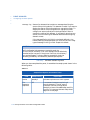
Math and Logic
Scaling and Deadbanding
FactoryLink ECS 6.0 / March / 1996
C1
•
•
•
•
©Copyright 1984 - 1996 United States Data Corporation. All rights reserved.
- NOTICE The information contained herein is confidential information of United States Data Corporation, a Delaware corporation,
and is protected by United States copyright and trade secret law and international treaties. This document may refer to
United States Data Corporation as “USDATA.”
Information in this document is subject to change without notice and does not represent a commitment on the part of United
States Data Corporation (“USDATA”). Although the software programs described in this document (the “Software
Programs”) are intended to operate substantially in accordance with the descriptions herein, USDATA does not represent
or warrant that (a) the Software Programs will operate in any way other than in accordance with the most current operating
instructions available from USDATA, (b) the functions performed by the Software Programs will meet the user's
requirements or will operate in the combinations that may be selected for use by the user or any third person, (c) the
operation of the Software Programs will be error free in all circumstances, (d) any defect in a Software Program that is not
material with respect to the functionality thereof as set forth herein will be corrected, (e) the operation of a Software
Program will not be interrupted for short periods of time by reason of a defect therein or by reason of fault on the part of
USDATA, or (f) the Software Programs will achieve the results desired by the user or any third person.
U.S. GOVERNMENT RESTRICTED RIGHTS. The Software is provided with RESTRICTED RIGHTS. Use, duplication, or
disclosure by the government of the United States is subject to restrictions as set forth in subparagraph (c)(1)(ii) of The
Rights in Technical Data and Computer Software clause at DFARS 252.227-7013 or in subparagraphs (c)(1) and (2) of the
Commercial Computer Software—Restricted Rights clause at 48 CFR 52.227-19, as applicable. Contractor/Manufacturer
is United States Data Corporation, 2435 North Central Expressway, Suite 100, Richardson, TX 75080-2722. To the extent
Customer transfers Software to any federal, state or local government agency, Customer shall take all acts necessary to
protect the rights of USDATA in Software, including without limitation all acts described in the regulations referenced
above.
The Software Programs are furnished under a software license or other software agreement and may be used or copied
only in accordance with the terms of the applicable agreement. It is against the law to copy the software on any medium
except as specifically allowed in the applicable agreement. No part of this manual may be reproduced or transmitted in any
form or by any means, electronic or mechanical, including photocopying and recording, for any purpose without the
express written permission of USDATA.
Trademarks. USDATA, FactoryLink and FactoryLink ECS are registered trademarks of United States Data Corporation.
Open Software Bus is a registered trademark licensed to United States Data Corporation.
All other brand or product names are trademarks or registered trademarks of their respective holders.
Table of Contents
Part title variable applied here in this
book
•
•
•
•
the Core Tasks Configuration Guide
Core Tasks
Configuration Guide
Part I
Persistence
1
Persistence . . . . . . . . . . . . . . . . . . . . . . . . . . . . . . . . . . . . . . . . . . . . . . . . . 13
Persistence Overview . . . . . . . . . . . . . . . . . . . . . . . . . . . . . . . . . .
Principles of Operation . . . . . . . . . . . . . . . . . . . . . . . . . . . . . . . . .
Resolving Configuration Changes . . . . . . . . . . . . . . . . . . . . . . . .
Configuring Persistence for Existing Applications . . . . . . . . . . .
Configuring Persistence for New Applications . . . . . . . . . . . . . .
Configuring Persistence for Individual Elements . . . . . . . . . . . .
Configuring Persistence for All Elements in a Domain . . . . . . .
Configuring the Persistence Task. . . . . . . . . . . . . . . . . . . . . . . . .
Persistence Task Start Order . . . . . . . . . . . . . . . . . . . . . . . . . . . .
Persistence and Digital Elements . . . . . . . . . . . . . . . . . . . . . . . .
Persistence Save File Name . . . . . . . . . . . . . . . . . . . . . . . . . . . . .
Editing Tag Persistence Settings Using BH_SQL Utility. . . . . .
........
........
........
........
........
........
........
........
........
........
........
........
.
.
.
.
.
.
.
.
.
.
.
.
13
15
17
18
18
19
21
23
26
27
29
30
Part II
Event and Interval Timer
2
Event and Interval Timer . . . . . . . . . . . . . . . . . . . . . . . . . . . . . . . . . . . 37
Principles of Operation . . . . . . . . . . . . . . . . . . . . . . . . . . . . . . . . . . . . . . . . . .
Changing the Operating System Date and Time. . . . . . . . . . . . . . . . . . . . . .
Configuring the Event and Interval Timer Task. . . . . . . . . . . . . . . . . . . . . .
Event Timer Information Dialog . . . . . . . . . . . . . . . . . . . . . . . . . . . . . . .
Interval Timer Information Dialog . . . . . . . . . . . . . . . . . . . . . . . . . . . . .
38
40
40
40
43
Part III
Programmable Counters
3
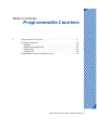
Programmable Counters . . . . . . . . . . . . . . . . . . . . . . . . . . . . . . . . . . . . 51
Principles of Operation . . . . . . . . . . . . . . . . . . . . . . . . . . . . . . . . . . . . . . . . . . 52
Elements . . . . . . . . . . . . . . . . . . . . . . . . . . . . . . . . . . . . . . . . . . . . . . . . . 52
FactoryLink ECS / Core Tasks Configuration Guide / 3
•
•
•
•
Core Tasks Configuration Guide
Digital and Analog Values . . . . . . . . . . . . . . . . . . . . . . . . . . . . . . . . . . .
Example One . . . . . . . . . . . . . . . . . . . . . . . . . . . . . . . . . . . . . . . . . . . . . .
Example Two . . . . . . . . . . . . . . . . . . . . . . . . . . . . . . . . . . . . . . . . . . . . . .
Programmable Counters Information Panel . . . . . . . . . . . . . . . . . . . . . . . . . .
52
53
53
55
Part IV
File Manager
4
File Manager . . . . . . . . . . . . . . . . . . . . . . . . . . . . . . . . . . . . . . . . . . . . . . . 65
File Manager Control Panel . . . . . . . . . . . . . . . . . . . . . . . . . . . . . . . . . . . . . . .
File Manager Information Panel . . . . . . . . . . . . . . . . . . . . . . . . . . . . . . . . . . .
Sample File Manager Operations . . . . . . . . . . . . . . . . . . . . . . . . . . . . . . . . . .
Example 1: COPY . . . . . . . . . . . . . . . . . . . . . . . . . . . . . . . . . . . . . . . . . .
Example 2: PRINT . . . . . . . . . . . . . . . . . . . . . . . . . . . . . . . . . . . . . . . . .
Example 3: REN (Rename) . . . . . . . . . . . . . . . . . . . . . . . . . . . . . . . . . . .
Example 4: TYPE . . . . . . . . . . . . . . . . . . . . . . . . . . . . . . . . . . . . . . . . . .
Example 5: DIR (Directory) . . . . . . . . . . . . . . . . . . . . . . . . . . . . . . . . . .
Example 6: DEL (Delete) . . . . . . . . . . . . . . . . . . . . . . . . . . . . . . . . . . . . .
Using Variable Specifiers in File Specifications . . . . . . . . . . . . . . . . . . . . . . .
Using Wildcard Characters in File Specifications. . . . . . . . . . . . . . . . . . . . . .
Using the File Manager with Networks . . . . . . . . . . . . . . . . . . . . . . . . . . . . .
Using the COPY Command with FLLAN . . . . . . . . . . . . . . . . . . . . . . . .
Using the COPY Command with a Network without FLLAN . . . . . . . . .
Technical Notes . . . . . . . . . . . . . . . . . . . . . . . . . . . . . . . . . . . . . . . . . . . . . . . . .
Operating System Notes. . . . . . . . . . . . . . . . . . . . . . . . . . . . . . . . . . . . . . . . . .
For Windows NT and Windows 95 Users . . . . . . . . . . . . . . . . . . . . . . . .
For OS/2 Users . . . . . . . . . . . . . . . . . . . . . . . . . . . . . . . . . . . . . . . . . . . .
For Unix Users . . . . . . . . . . . . . . . . . . . . . . . . . . . . . . . . . . . . . . . . . . . .
66
74
76
76
79
80
81
82
84
85
87
88
89
92
93
94
94
96
98
Part V
Print Spooler
5
Print Spooler . . . . . . . . . . . . . . . . . . . . . . . . . . . . . . . . . . . . . . . . . . . . . 105
Configuring the Print Spooler . . . . . . . . . . . . . . . . . . . . . . . . . . . . . . . . . . . . 106
4 / FactoryLink ECS / Core Tasks Configuration Guide
Core Tasks Configuration Guide
Part VI
Math and Logic
6
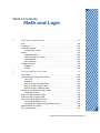
Math and Logic Overview . . . . . . . . . . . . . . . . . . . . . . . . . . . . . . . . . . 119
Uses . . . . . . . . . . . . . . . . . . . . . . . . . . . . . . . . . . . . . . . . . . . . . . . . . . . . . . . . . 120
Procedures . . . . . . . . . . . . . . . . . . . . . . . . . . . . . . . . . . . . . . . . . . . . . . . . . . . . 121
Creating Programs . . . . . . . . . . . . . . . . . . . . . . . . . . . . . . . . . . . . . . . . . . . . . 122
Configuration Tables. . . . . . . . . . . . . . . . . . . . . . . . . . . . . . . . . . . . . . . 122
Modes . . . . . . . . . . . . . . . . . . . . . . . . . . . . . . . . . . . . . . . . . . . . . . . . . . . . . . . . 124
Interpreted Mode . . . . . . . . . . . . . . . . . . . . . . . . . . . . . . . . . . . . . . . . . . 124
Switching from IML to CML . . . . . . . . . . . . . . . . . . . . . . . . . . . . . . . . . 125
Compiled Mode . . . . . . . . . . . . . . . . . . . . . . . . . . . . . . . . . . . . . . . . . . . 125
CML Operation . . . . . . . . . . . . . . . . . . . . . . . . . . . . . . . . . . . . . . . . . . . 126
Triggering/Calling . . . . . . . . . . . . . . . . . . . . . . . . . . . . . . . . . . . . . . . . . . . . . . 128
Triggering . . . . . . . . . . . . . . . . . . . . . . . . . . . . . . . . . . . . . . . . . . . . . . . 128
Calling . . . . . . . . . . . . . . . . . . . . . . . . . . . . . . . . . . . . . . . . . . . . . . . . . . 128
7
Configuring Math and Logic . . . . . . . . . . . . . . . . . . . . . . . . . . . . . . . 131
Text Editor. . . . . . . . . . . . . . . . . . . . . . . . . . . . . . . . . . . . . . . . . . . . . . . . . . . . 132
Math and Logic Configuration Tables . . . . . . . . . . . . . . . . . . . . . . . . . . . . . . 133
.PRG Files . . . . . . . . . . . . . . . . . . . . . . . . . . . . . . . . . . . . . . . . . . . . . . . 134
Comments . . . . . . . . . . . . . . . . . . . . . . . . . . . . . . . . . . . . . . . . . . . . . . . 135
Math and Logic Variables Table . . . . . . . . . . . . . . . . . . . . . . . . . . . . . . 135
Math and Logic Triggers Table. . . . . . . . . . . . . . . . . . . . . . . . . . . . . . . 136
Math and Logic Procedure Table . . . . . . . . . . . . . . . . . . . . . . . . . . . . . 136
Configuring the Math and Logic Tables . . . . . . . . . . . . . . . . . . . . . . . . . . . . 137
Choosing a Domain . . . . . . . . . . . . . . . . . . . . . . . . . . . . . . . . . . . . . . . . 137
Math and Logic Variables Table . . . . . . . . . . . . . . . . . . . . . . . . . . . . . . . . . . 138
Math and Logic Triggers Table . . . . . . . . . . . . . . . . . . . . . . . . . . . . . . . . . . . 140
Math and Logic Procedures Table . . . . . . . . . . . . . . . . . . . . . . . . . . . . . . . . . 143
Correcting Validation Errors . . . . . . . . . . . . . . . . . . . . . . . . . . . . . . . . 145
Configuration Examples Using Element Arrays . . . . . . . . . . . . . . . . . . 146
Compiled Math and Logic. . . . . . . . . . . . . . . . . . . . . . . . . . . . . . . . . . . . . . . . 149
CML Requirements . . . . . . . . . . . . . . . . . . . . . . . . . . . . . . . . . . . . . . . . . . . . . 150
Entering CML Into the System Configuration Table . . . . . . . . . . . . . . . . . . 152
Running CML . . . . . . . . . . . . . . . . . . . . . . . . . . . . . . . . . . . . . . . . . . . . . . . . . 153
Running CML on a Development System . . . . . . . . . . . . . . . . . . . . . . . 153
FactoryLink ECS / Core Tasks Configuration Guide / 5
•
•
•
•
Core Tasks Configuration Guide
Running CML on a Run-Time-Only System . . . . . . . . . . . . . . . . . . . . . 153
How CML Operates. . . . . . . . . . . . . . . . . . . . . . . . . . . . . . . . . . . . . . . . . . . . . 155
Makefiles . . . . . . . . . . . . . . . . . . . . . . . . . . . . . . . . . . . . . . . . . . . . . . . . 159
Editing CML.MAK . . . . . . . . . . . . . . . . . . . . . . . . . . . . . . . . . . . . . . . . 159
Advanced Concepts for CML . . . . . . . . . . . . . . . . . . . . . . . . . . . . . . . . . . . . . 161
Utilities and Commands . . . . . . . . . . . . . . . . . . . . . . . . . . . . . . . . . . . . 161
Calling C Code. . . . . . . . . . . . . . . . . . . . . . . . . . . . . . . . . . . . . . . . . . . . . . . . . 164
8
Math and Logic Syntax . . . . . . . . . . . . . . . . . . . . . . . . . . . . . . . . . . . . 173
Procedure Tokens . . . . . . . . . . . . . . . . . . . . . . . . . . . . . . . . . . . . . . . . . . . . . . 174
Naming Procedures . . . . . . . . . . . . . . . . . . . . . . . . . . . . . . . . . . . . . . . . 174
Math and Logic Reserved Keywords . . . . . . . . . . . . . . . . . . . . . . . . . . . . . . . 176
Comments . . . . . . . . . . . . . . . . . . . . . . . . . . . . . . . . . . . . . . . . . . . . . . . . . . . . 179
Constants. . . . . . . . . . . . . . . . . . . . . . . . . . . . . . . . . . . . . . . . . . . . . . . . . . . . . 181
Symbolic Constants . . . . . . . . . . . . . . . . . . . . . . . . . . . . . . . . . . . . . . . . 181
Numeric Constants . . . . . . . . . . . . . . . . . . . . . . . . . . . . . . . . . . . . . . . . 182
String Constants . . . . . . . . . . . . . . . . . . . . . . . . . . . . . . . . . . . . . . . . . . 184
Structure . . . . . . . . . . . . . . . . . . . . . . . . . . . . . . . . . . . . . . . . . . . . . . . . . . . . . 187
Declarations. . . . . . . . . . . . . . . . . . . . . . . . . . . . . . . . . . . . . . . . . . . . . . 187
Expressions . . . . . . . . . . . . . . . . . . . . . . . . . . . . . . . . . . . . . . . . . . . . . . 207
Statements . . . . . . . . . . . . . . . . . . . . . . . . . . . . . . . . . . . . . . . . . . . . . . . 220
Directives . . . . . . . . . . . . . . . . . . . . . . . . . . . . . . . . . . . . . . . . . . . . . . . . 228
9
Math and Logic Procedures and Functions . . . . . . . . . . . . . . . . . . 231
Program Files . . . . . . . . . . . . . . . . . . . . . . . . . . . . . . . . . . . . . . . . . . . . . . . . . 231
Procedures . . . . . . . . . . . . . . . . . . . . . . . . . . . . . . . . . . . . . . . . . . . . . . . 232
Arguments . . . . . . . . . . . . . . . . . . . . . . . . . . . . . . . . . . . . . . . . . . . . . . . 233
Running Programs as Interpreted Programs . . . . . . . . . . . . . . . . . . . . . . . . 235
Technical Notes . . . . . . . . . . . . . . . . . . . . . . . . . . . . . . . . . . . . . . . . . . . . . . . . 236
Calling Procedures and Functions . . . . . . . . . . . . . . . . . . . . . . . . . . . . 236
Local Procedures . . . . . . . . . . . . . . . . . . . . . . . . . . . . . . . . . . . . . . . . . . 236
Library Functions . . . . . . . . . . . . . . . . . . . . . . . . . . . . . . . . . . . . . . . . . 237
Calling Functions that Operate on Tag IDs (CML Only) . . . . . . . . . . . 248
10
Compiled Math and Logic . . . . . . . . . . . . . . . . . . . . . . . . . . . . . . . . . . 251
System Configuration Panel Setup Under IML/CML. . . . . . . . . . . . . . . . . . 253
6 / FactoryLink ECS / Core Tasks Configuration Guide
Core Tasks Configuration Guide
Makefiles . . . . . . . . . . . . . . . . . . . . . . . . . . . . . . . . . . . . . . . . . . . . . . . . . . . . . 254
Editing CML.MAK . . . . . . . . . . . . . . . . . . . . . . . . . . . . . . . . . . . . . . . . 254
The CML Process. . . . . . . . . . . . . . . . . . . . . . . . . . . . . . . . . . . . . . . . . . . . . . . 256
Generation of CML Executables. . . . . . . . . . . . . . . . . . . . . . . . . . . . . . . . . . . 257
Part VII Scaling & Deadbanding
11
Scaling & Deadbanding . . . . . . . . . . . . . . . . . . . . . . . . . . . . . . . . . . . 273
Principles of Operation . . . . . . . . . . . . . . . . . . . . . . . . . . . . . . . . . . . . . . . . . . 274
Defining Scaling and Deadbanding Operations . . . . . . . . . . . . . . . . . . . . . . 276
FactoryLink ECS / Core Tasks Configuration Guide / 7
•
•
•
•
Core Tasks Configuration Guide
8 / FactoryLink ECS / Core Tasks Configuration Guide
Core Tasks Configuration Guide
•
•
•
•
•
•
•
•
•
•
•
•
•
•
•
•
•
•
•
•
•
•
•
•
•
•
•
•
•
•
Part I
Persistence
Table of Contents
•
•
•
•
Persistence in the Core Tasks Configuration Persistence in this book
Guide
Persistence
1
Persistence . . . . . . . . . . . . . . . . . . . . . . . . . . . . . . . . . . . . . . . . . . . . . . . . . 13
Persistence Overview . . . . . . . . . . . . . . . . . . . . . . . . . . . . . . . . . .
Principles of Operation . . . . . . . . . . . . . . . . . . . . . . . . . . . . . . . . .
Resolving Configuration Changes . . . . . . . . . . . . . . . . . . . . . . . .
Configuring Persistence for Existing Applications . . . . . . . . . . .
Configuring Persistence for New Applications . . . . . . . . . . . . . .
Configuring Persistence for Individual Elements . . . . . . . . . . . .
Configuring Persistence for All Elements in a Domain . . . . . . .
Configuring the Persistence Task. . . . . . . . . . . . . . . . . . . . . . . . .
Persistence Task Start Order . . . . . . . . . . . . . . . . . . . . . . . . . . . .
Persistence and Digital Elements . . . . . . . . . . . . . . . . . . . . . . . .
Persistence Save File Name . . . . . . . . . . . . . . . . . . . . . . . . . . . . .
Editing Tag Persistence Settings Using BH_SQL Utility. . . . . .
........
........
........
........
........
........
........
........
........
........
........
........
.
.
.
.
.
.
.
.
.
.
.
.
13
15
17
18
18
19
21
23
26
27
29
30
FactoryLink ECS / Core Tasks Configuration Guide / 11
•
•
•
•
Persistence
12 / FactoryLink ECS / Core Tasks Configuration Guide
•
•
•
•
Chapter 1
Persistence
1
PE RSISTEN CE OVER VIEW
The memory-based real-time database represents the current state (values) of
elements. The real-time database is a collection of domain instances. Elements in
the database may have default values which are placed into the domain instance
when it is initialized.
The values of the elements in a domain instance are lost when the domain
instance is closed. When the domain instance is opened again, its elements are
initialized to their default values.
This can be a problem if FactoryLink unexpectedly shuts down because of an
event such as a power loss or a faulty process. Useful information can be lost
because of the initialization of the real-time database to its default values when
the system is restarted. Since most of the information in FactoryLink applications
is the accumulation of data over time, you cannot recover this data unless it is
saved. Persistence provides a way of saving the state of an active FactoryLink
application.
Persistence is the ability of an element to maintain its value over an indefinite
period of time. Non-persistent elements lose their value when the Run-Time
Manager exits and shuts down the real-time database. However, the values of
persistent elements are written to disk so they are not affected when the real-time
database shuts down.
The job of the Persistence task, therefore, is to save persistent data. The task
offers the following features.
• Runs on all FactoryLink platforms.
• Lets you configure on a per-tag basis or on entire domains which elements are
persistent and when their values are saved to disk.
FactoryLink ECS / Core Tasks Configuration Guide / 13
Persistence
Use the Persistence task to save the values of an activeFactoryLink application at
predetermined times so if FactoryLink is shut down unexpectedly, useful data is
not lost. Then, when you restart FactoryLink with the warm start command-line
option, the Run-Time Manager restores the last save of the real-time database
from the persistence save file.
•
•
•
•
PERSISTENCE
Persistence Overview
• Saves one or all domain instances to disk while a FactoryLink application is
•
•
•
•
running.
Allows you to specify either a warm or cold start when initializing a domain
instance.
Cold start initializes all elements to their default values as configured in the
Configuration Manager Main Menu. Persistent elements are not restored to
their previous values but are initialized to their default values.
Warm start initializes all non-persistent elements to their default values just
like a cold start and restores all persistent elements in the domain instance to
their previously saved values.
Uses its own internal disk cache to increase speed and reduce disk I/O
overhead.
Resolves configuration changes to the application.
Allows you to specify a trigger element that triggers the Persistence task to
copy the current save file to a backup file.
14 / FactoryLink ECS / Core Tasks Configuration Guide
PERSISTENCE
Principles of Operation
PRI NCIPLES
OF
O PERA TION
1
At run time, the Persistence task saves the values of the persistent elements to its
own internal disk cache and the task writes the data to disk from there. Saving
the persistent values to memory first increases processing speed and ensures all
values meant to be saved are saved within the allotted time.
The Persistence task runs under each domain that requires persistent data to be
saved. The RESOLVE program (executed by the FLRUN command) creates a
blank persistence save file for each domain the first time it is executed. During its
initialization, the Persistence task loads the persistence save file to determine
which elements in the application are persistent and when the values of those
elements are to be saved. It also loads the PERSIST.CT file to get specific
information about the configuration of the Persistence task itself.
When you perform a warm start, the current domain’s Run-Time Manager
restores the domain instance’s real-time database from the persistence save file. It
restores the values of the persistent elements to the last values saved by
Persistence.
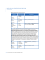
To perform a warm start of FactoryLink, use the warm start argument -w. In
Windows and OS/2, add the -w to the command line for the icon used to start
FactoryLink; in UNIX, either pass the -w to the FLRUN command, or add it to the
line in the script file used to start FactoryLink.
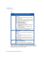
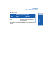
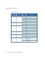
See the table below for details:
FactoryLink ECS / Core Tasks Configuration Guide / 15
Persistence
Persistence begins during application development. Whether configuring a new
application or reconfiguring an existing application, you must first determine
which elements are persistent, when the values of the persistent elements are
saved to disk, and how these saved values are restored during a warm start. Then,
specify this information on the Tag Definition dialog when defining a persistent
element.
•
•
•
•
PERSISTENCE
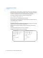
Principles of Operation
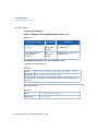
Table 1-1
Starting FactoryLink using the -w (warm start)
Windows
Create a new Start FactoryLink icon, following the
steps below:
1. Click once on the Start FactoryLink icon to select it.
2. Click Edit>Copy.
3. Click Edit>Paste. A copy of the Start FactoryLink
icon is pasted into the FactoryLink Program Group.
It is labelled Copy of Start FactoryLink.
4. Change its properties by:
a.) clicking File>Properties
b.) clicking in the command line,
c.) pressing the End key (to get to the end of the
command line)
d.) adding -w to the end of the command line,
preceded by a space.
5. Click File>Rename and change the icon’s label to
Warm Start FactoryLink. Press the Enter key.
OS/2
Create a new Run Time Manager icon, following the
steps below:
1. Right click once on the Run Time Manager icon to
select it.
2. Click Copy.
a. Enter Warm Start for the icon’s new name.
b. Click Copy.
3. Right click once on the Warm Start icon to select it.
4. Click Settings. In Optional Parameters, type -w.
5. Close window.
UNIX
Edit the command line as
$ flrun -w -d -nshared <ret>
or add the -w to the script file using above syntax.
Before starting the Run-Time Manager, the FLRUN command executes the
RESOLVE program to check the persistence save file for any configuration
changes you made. The need to check for configuration changes is discussed in
“Resolving Configuration Changes” on page 17.
16 / FactoryLink ECS / Core Tasks Configuration Guide
PERSISTENCE
Resolving Configuration Changes
R ESOLVI NG C ON FIGUR ATIO N C H ANG ES
This resolving of configuration changes is done by the RESOLVE.EXE (resolve on
UNIX systems) program. The FLRUN command automatically executes this
program before it starts the Run-Time Manager for a particular FactoryLink
session.
The RESOLVE program serves three purposes.
• Creates the blank persistence save file the first time it is run.
• Manages the changes between the persistence save file and the FactoryLink
configuration files.
• Determines if the persistence save file is usable and, if not, the program looks
for and uses the persistence backup file.
RESOLVE makes the following changes.
• Removes element names from the persistence save file that have been deleted
from the application or changed to a different data type.
• Updates the element name ID for element names that were deleted, then
recreated.
• Adds element names to the persistence save file that have been reconfigured to
have persistence. These element names are added with no data values.
• Copies the persistence backup file over the persistence save file if the save file is
corrupted.
FactoryLink ECS / Core Tasks Configuration Guide / 17
1
Persistence
After you shut down a FactoryLink application, you might reconfigure part of the
application using the Main Menu or the Application Editor. This means the
elements and their values stored in the persistence save file either may not exist
or might not have the same data type when you restart the application. Before
each FactoryLink session is restarted, the element names stored in the
persistence save file must be checked for changes against the OBJECT.CT and the
DOMAIN.CT files.
•
•
•
•
PERSISTENCE
Configuring Persistence for Existing Applications
C ON FIGUR ING P ERSIS TENCE
FOR
E XISTIN G A PPLICA TIONS
The methods for configuring persistence are the same for both new and existing
applications. For existing applications, however, you must first run the
FactoryLink Conversion Utility (FLCONV). FLCONV assigns the following
default persistence options to an existing application:
• Saving—No persistence
• Restoring—Set Change Status OFF
After you run the FLCONV utility, you can change the persistence options for the
elements in that application. Determine the database elements in the application
to be persistent and configure persistence for the elements, either individually or
for the entire domain. These methods are explained in “Configuring Persistence
for New Applications” on page 18.
C ON FIGUR ING P ERSIS TENCE
FOR
N EW A PPLIC ATION S
To use the warm start feature, you must configure which elements are persistent,
when their values will be saved, and how to restore their change-status bits
during a warm start of FactoryLink.
You can configure persistence in one of two ways.
• For individual elements.
• For all of the elements in a domain.
The following sections discuss how to configure persistence for both cases.
18 / FactoryLink ECS / Core Tasks Configuration Guide
PERSISTENCE
Configuring Persistence for Individual Elements
C ONFIG URI NG PE RSISTEN CE
FOR I NDIVID UAL
ELE MEN TS
Perform the following steps to configure persistence for individual elements.
1 Define a new element or press Ctrl- to display the Tag Definition dialog.
2 Choose the required options from the Persistence section of the Tag Definition
dialog.
Use Domain
Settings
Saves the value of the persistent element according to the options
chosen for the domain’s persistence. The Saving and Restoring
options are disabled when this option is chosen.
Deselect Use Domain Settings to enable the Saving and Restoring
options for this element specifically.
FactoryLink ECS / Core Tasks Configuration Guide / 19
1
Persistence
Configure persistence for individual elements in the Tag Definition dialog. The Tag
Definition dialog is displayed when you
• Define a new element in either a configuration panel from the Main Menu or in
an animation panel in the Application Editor.
• Press Ctrl-T in a Tag field for a previously defined element.
•
•
•
•
PERSISTENCE
Configuring Persistence for Individual Elements
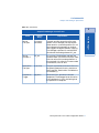
Saving
Indicates when the value of the persistent element is saved. This
can be one of the following.
On Time—Saves the value of the persistent element on a timed
trigger.
On Exception—Saves the value of the persistent element
whenever its value changes.
On Time and On Exception—Saves the value of the persistent
element on a timed trigger and when its value changes.
Restoring
Indicates how to restore the persistent element. This can be one
of the following:
Set Change Status ON—Restores the persistent element with its
change-status bits set to 1 (ON) after a warm start.
Set Change Status OFF—Restores the persistent element with its
change-status bits set to 0 (OFF) after a warm start. This is the
default.
No Options Selected—The element is not marked as persistent.
20 / FactoryLink ECS / Core Tasks Configuration Guide
PERSISTENCE
Configuring Persistence for All Elements in a Domain
C ONFIG URI NG PE RSISTEN CE
FOR
A LL ELEM ENTS
IN A
D OM AIN
1
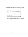
Complete the following steps to configure persistence for all elements in a domain
in the Domain Element List.
The list includes the domain name, the parent domain, the number of application
instances available for the domain, domain persistence, and the setting for change
bits. Use the Persistence and Change Bits fields to configure persistence for an
entire domain.
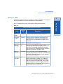
2 Choose the Persistence field for the row containing the domain to be made
persistent. Enter the method you want to use to save the elements’ values. This
can be one of the following.
None
The elements in the domain are not marked as persistent.
Timed
Saves the values of the domain’s elements on a timed trigger.
Except
Saves the values of the domain’s elements whenever their values
change.
Both
Saves the values of the domain’s elements both on a timed trigger
and whenever their values change.
3 Choose the Change Bits field for the same domain and enter how you want to
restore the elements’ change-status bits. This can be one of the following.
ON
Restores the domain’s elements with their change-status bits set
to 1 (ON) after a warm start.
OFF
Restores the domain’s elements with their change-status bits set
to 0 (OFF) after a warm start.
FactoryLink ECS / Core Tasks Configuration Guide / 21
Persistence
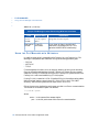
1 Choose View>Domain List to display the Domain Element List.
•
•
•
•
PERSISTENCE
Configuring Persistence for All Elements in a Domain
For example, you may have several Math & Logic procedures
triggered by digital tags, but the application controls when these
tags are force-written to a 1 (value=1; change-status bits=1). If
you perform a warm start with Change Bits ON, then all of the
digital tags’ change-status bits are written to a 1 and all of your
IML procs run at once.
22 / FactoryLink ECS / Core Tasks Configuration Guide
PERSISTENCE
Configuring the Persistence Task
C ONFIG URI NG
THE
PE RSISTEN CE T ASK
1
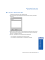
In addition to configuring persistence for elements and domains, you must also
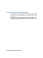
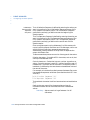
configure the operation of the Persistence task itself. Choose Persistence to display
the Persistence Save Information panel.
Persistence
Following are field descriptions for this panel.
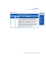
Timed Save
Trigger
Name of an element used to trigger a timed save of the values of
all elements marked as persistent by time.
When the element defined here is triggered at run time, the
Persistence task reads all elements in the current domain
instance configured to be saved on a timed basis and writes their
values to disk (the persistence save file).
Leave this field blank if no timed saves are required for the
application.
A Tag Definition dialog is displayed when you click on Enter if the
tag specified in this field is not already defined.
Valid Entry: standard element tag name
Valid Data Type: digital, analog, longana, float, message
FactoryLink ECS / Core Tasks Configuration Guide / 23
•
•
•
•
PERSISTENCE
Configuring the Persistence Task
Cache Buffers
Number between 0 and 32766 indicating the number of buffers to
be set aside for the Persistence task’s internal disk cache. The
default is 16. The greater the number of buffers, the less the task
writes to the disk, which improves performance.
Use the following guidelines to aid in determining the number of
buffers:
- How often the data is changing
- How much of the data is changing
- The size of the data that is changing
While there is no definitive way to determine the ideal number of
buffers, you can use the total number of tags of each data type
that are persistent in the application to calculate an estimation of
the maximum buffer size. The formula is given as follows:
max buffer size = [(# of analog + digital)*2] + [(# of longana)*4] +
[(# of float)*8] + [(# of msg)*len]
where len is the message length from the Persistence panel.
Then select a combination of number of buffers multiplied by
buffer size that equals this value. (See Buffer Size, below.)
If you enter 0, no disk caching is done. This can be desirable if the
operating system itself uses an efficient disk caching system
(such as UNIX).
Valid Entry: numeric value of up to 32766 (default = 16)
Buffer Size
Number between 64 and 32766 indicating the size, in bytes, of
each buffer in the cache. The default is 512. The larger the buffer,
the less the task writes to the disk, which improves performance.
Valid Entry: numeric value of up to 32766 (default = 512)
Message Copy
Size
Number between 80 and 32766 indicating the maximum length
allowed for message elements during persistent saves.
FactoryLink uses the number entered here when it reads
elements from the real-time database, and when restoring values
during a warm start. The default is 2048.
Valid Entry: numeric value of up to 32766 (default = 2048)
24 / FactoryLink ECS / Core Tasks Configuration Guide
PERSISTENCE
Configuring the Persistence Task
Backup Trigger
Name of an element used to trigger a backup of the current
persistent save file.
1
A Tag Definition dialog is displayed when you click on Enter if the
tag specified in this field is not already defined.
Valid Entry: standard element tag name
Valid Data Type: digital, analog, longana, float, message
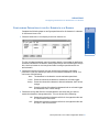
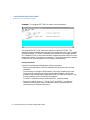
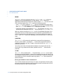
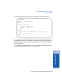
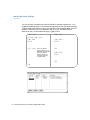
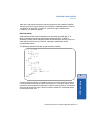
The completed panel resembles the following sample:
In this example, when the value of the element persist_trig changes to 1 (ON), it
triggers the Persistence task to write to disk the values of all elements in the
application configured as persistent by time. The number of buffers set aside for
the internal cache is 16 with 512 bytes per buffer. A disk cache is a way to
compensate for the slowness of the disk drive in comparison to RAM (memory).
The Persistence task’s cache process speeds up computer operations by keeping
data in memory. Rather than writing each piece of data to be saved to the hard
disk, the task writes the data to its internal disk cache (reserved memory area).
Then, when the disk is not busy with other processing or when the cache process
can perform several writes in an order that minimizes the movements of the disk’s
heads, the cache process writes the saved data to the hard disk.
The maximum length for message elements during persistent saves is 2048 bytes.
When the value of the element persist_backup changes to 1, it triggers Persistence
to copy the current persistence save file to a backup file.
FactoryLink ECS / Core Tasks Configuration Guide / 25
Persistence
At run time, when the application triggers the element defined
here, the Persistence task copies the current persistence save file
to a backup file.
•
•
•
•
PERSISTENCE
Persistence Task Start Order
PE RSISTEN CE T ASK S TART OR DER
This section describes some possible effects of warm restarts on the application
depending on when Persistence starts and what has happened to the other tasks
during the startup process. This discussion ONLY applies if the TASKSTART_?
tags (from the System Configuration Table) are made persistent.
Example 1: Persistence starts last and shuts down first
After the application starts, the values of the TASKSTART_? tags are 1, so
Persistence saves a 1 as their last known value. At shutdown, because Persistence
stops first, Persistence does not “see” the change in value of the TASKSTART_?
tags from 1 to 0 (zero), so the saved values remain as 1. On a warm start of the
application, the TASKSTART_? tags for all tasks that were running at shutdown
will be restored to 1 and therefore, their tasks will start. It is important to note
that these same tasks will be started regardless of their “R” flag settings in the
SYS.CT file. (This assumes no manual starts/terminations.)
Example 2: Persistence starts first and shuts down last
Because Persistence starts first, it “sees” the application starting and therefore
sees the values of the TASKSTART_? tags at 0. If there is a termination during
the startup process, then, because Persistence stops last, it saves a 0 as the last
known value of the TASKSTART_? tags. On a warm start of the application, none
of the tasks will be started because all of the tasks’ TASKSTART_? tags had a last
known value of 0.
The shutdown order is more significant than the startup order if the tags are
saved on change. In general, specify the Persistence task to shutdown first (and
therefore, start last) so that the saved values in the Persistence save file reflect
the last known running state of the application at shutdown. Then, the warm
start will restore it to that state, which is the purpose of the Persistence task.
26 / FactoryLink ECS / Core Tasks Configuration Guide
PERSISTENCE
Persistence and Digital Elements
PER SISTENC E
A ND
D IGITA L E LEM ENTS
However, the digital elements RTMCMD and RTMCMD_U, cannot be made
persistent. This is because when the value of these elements is set to 1, the
FactoryLink system shuts down. Therefore, making these elements persistent
immediately shuts down the system as soon as it comes up.
Note that the R (Run) flag for each task in the System Configuration Information
panel supersedes the value of the digital start trigger associated with a task.
Examples
The following examples show the relationship between the R flag in the System
Configuration Information panel and the restored value of a digital element:
Example 1:
The R flag is NOT set for task A and the digital start trigger associated with task
A is defined as persistent by Exception (always updated) with Force Change
Status ON if:
• Task A is running when the system is shut down, then the value of the task’s
digital start trigger is 1. When a warm start is performed, the system restarts
task A because the value of the digital start trigger is restored to 1.
• Task A is not running when the system is shut down, then the value of the
task’s digital start trigger is 0. When a warm start is performed, the system
does not restart task A because the value of the digital start trigger is restored
to 0.
FactoryLink ECS / Core Tasks Configuration Guide / 27
1
Persistence
The way a digital element is used in an application affects how that element is
configured for persistence. Digital elements are often used to trigger some action
in an application. Examples include starting a Math and Logic procedure or
starting a FactoryLink task. When a digital element is triggered (its value is
changed from 0 to 1 or force-written to 1), FactoryLink starts the associated
procedure or task. When FactoryLink is warm-started, these elements are
restored to their last saved value. Configuring a digital element as persistent with
its value to be restored with Force Change Status ON can be used to start any
procedure or task associated with this element after the system is initialized.
•
•
•
•
PERSISTENCE
Persistence and Digital Elements
Example 2:
The R flag IS set for task A and the digital start trigger associated with task A is
defined to be persistent by Exception (always updated) with Force Change Status
ON if:
• Task A is running when the system is shut down, then the value of the task’s
digital start trigger is 1. When a warm start is performed, the system restarts
task A because the value of the digital start trigger is restored to 1.
• Task A is not running when the system is shut down, then the value of the
task's digital start trigger is 0. When a warm start is performed, the system still
restarts task A because, even though the value of the digital start trigger is
restored to 0, the task’s Run flag is set and the Run flag supersedes the restored
value of the digital start trigger.
28 / FactoryLink ECS / Core Tasks Configuration Guide
PERSISTENCE
Persistence Save File Name
PER SISTENC E S AVE F ILE N AM E
1
The persistent data is saved in a unique persistence save file for each domain
instance. The persistence save files have the extension.PRS and are located in the
/FLAPP/FLNAME/FLDOMAIN directory.
FLAPP
is the translated application environment variable.
FLNAME
is the translated application environment variable.
FLDOMAIN
is the translated domain environment variable.
The name of each persistence save file is {FLUSER}.PRS where FLUSER is the
translated environment variable for the domain user name. The persistence save
file contains the saved values for that domain user.
For example, in Windows, where the FLRUN.BAT file sets the Shared FLUSER
environment variable to SHAREUSR, but the User domain FLUSER environment
variable remains at the default setup in the AUTOEXEC.BAT file, the Shared
persist file is named SHAREUSR.PRS and the User persist file is named
FLUSER1.PRS.
The persistence backup files are in the same place and have the same name,
except they have the extension.BAK (.bak in UNIX).
FactoryLink ECS / Core Tasks Configuration Guide / 29
Persistence
where
•
•
•
•
PERSISTENCE
Editing Tag Persistence Settings Using BH_SQL Utility
ED ITING T A G PER SISTENC E S ETTIN GS U SING BH_SQL U TILITY
It may be useful for users to be able to make mass edits to the current persistence
settings for defined tags in the OBJECT configuration table, such as changing the
field entries for all tags that currently are blank, to a specific setting such as
NONE. This can be done using the BH_SQL utility provided with all FactoryLink
systems. This utility
1. Modifies the OBJECT.CDB file in the FLAPP directory.
2. Modifies the TAGPERWHEN field in that file.
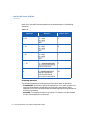
TAGPERWHEN (meaning “Tag is saved when?”) is the text equivalent of the radio
buttons seen on the Tag Definition dialog when defining a tag or using CTRL-T to
view the tag definition. The possible values are:
• NONE - tag is not persistent
• left blank - same as NONE
• DOMAIN - save based on domain persistence definition as configured in the
Domain configuration panel.
• TIMED- save on timed trigger
• EXCEPT - save on change
The procedure updates the table changing all instances of a specific entry in the
TAGPERWHEN field at one time to a new value.
Prior to executing the instructions below, we recommend you make a backup of
the application using the FLSAVE utility or some other backup utility. At least
make a backup copy of the OBJECT.CDB and OBJECT.MDX files so if anything
goes wrong during the procedure, the backup can be restored with no damage
done to the application. The general syntax can be modified to update the
persistence setting for any group of tags from the current settings to any valid
new setting as a group, by varying the literal values in the first and second
instance of tagperwhen = '????'.
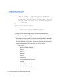
Follow the steps below to use the BH_SQL utility:
1. Run BH_SQL by typing the program name at a prompt for all systems except
MS Windows. For MS Windows, run the program from the Program Manager File>Run menu selection.
30 / FactoryLink ECS / Core Tasks Configuration Guide
PERSISTENCE
Editing Tag Persistence Settings Using BH_SQL Utility
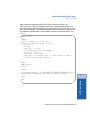
2. Type at the BH_SQL prompt:
SQL >
connect
1
flapp <ret>
3. Type at the BH_SQL prompt (quote marks are all single quotes not double
quotes):
SQL > update object set tagperwhen = 'NONE' where tagperwhen =
'' <ret>
where the first instance of tagperwhen = 'NONE' is the desired new value for the
field and the second instance is the current value of the field (in this case a blank
entry). This command finds all records in the OBJECT table for which the current
tag persistence setting is blank and changes all the settings to NONE.
Use the following command if you have a large number of tags configured to be
saved as defined for the domain configuration and you want to change the setting
for all of these tags to be saved individually when they change value or on
exception.
SQL > update object set tagperwhen = 'DOMAIN' where tagperwhen =
'EXCEPT' <ret>
Type QUIT at the BH_SQL prompt once all desired changes have been made.
FactoryLink ECS / Core Tasks Configuration Guide / 31
Persistence
where flapp is the actual path to the flapp directory as defined in the FLAPP
environment variable.
•
•
•
•
PERSISTENCE
Editing Tag Persistence Settings Using BH_SQL Utility
32 / FactoryLink ECS / Core Tasks Configuration Guide
Core Tasks Configuration Guide
•
•
•
•
•
•
•
•
•
•
•
•
•
•
•
•
•
•
•
•
•
•
•
•
•
•
•
•
•
•
Part II
Event and Interval Timer
Table of Contents
•
•
•
•
Event and Interval Timer in the Core Tasks Con- Event and Interval Timer in this book
figuration Guide
Event and Interval Timer
2
Event and Interval Timer . . . . . . . . . . . . . . . . . . . . . . . . . . . . . . . . . . . 37
Principles of Operation . . . . . . . . . . . . . . . . . . . . . . . . . . . . . . . . . . . . . . . . . .
Changing the Operating System Date and Time. . . . . . . . . . . . . . . . . . . . . .
Configuring the Event and Interval Timer Task. . . . . . . . . . . . . . . . . . . . . .
Event Timer Information Dialog . . . . . . . . . . . . . . . . . . . . . . . . . . . . . . .
Interval Timer Information Dialog . . . . . . . . . . . . . . . . . . . . . . . . . . . . .
38
40
40
40
43
FactoryLink ECS / Core Tasks Configuration Guide / 35
•
•
•
•
Event and Interval Timer
36 / FactoryLink ECS / Core Tasks Configuration Guide
•
•
•
•
Chapter 2
Event and Interval
Timer
Use the Event and Interval Timer task to define timed events and time intervals
that initiate and control any system function in run-time mode.
• Timed events occur at a specific time not more than once every 24 hours (for
example, Monday at 8:00 am). They are configured in the Event Timer Table.
• Time intervals occur at least once every twenty-four hours at regular intervals
of the system clock (for example, every 60 seconds). They are configured in the
Interval Timer Table.
The Event and Interval Timer task links timed events and intervals to real-time
database elements used as triggers whenever the event or interval occurs. It is
defined in the SHARED domain.
There is no limit, except the amount of available memory, to the number of event
and interval timers that can be defined.
FactoryLink ECS / Core Tasks Configuration Guide / 37
Event and Interval
Timer
The use of Event and Interval timers requires an understanding of change-status
flags. Refer to the FactoryLink Fundamentals manual for this discussion.
2
•
•
•
•
EVENT AND INTERVAL TIMER
Principles of Operation
PR INCIP LES
OF
O PER ATION
The Event and Interval Timer task operates in synchronization with the system
clock. For each defined interval or event, you must create a digital element in the
real-time database. When the system clock matches the specified event or
interval, the task forces the value of this digital element to 1 (ON).
The Event and Interval Timer task also updates global information used by
FactoryLink such as the current time, the day of the week, and the month. Such
global information is stored in predefined FactoryLink real-time database
elements, known as reserved elements, each of which is one of the following data
types: analog, long analog, or message.
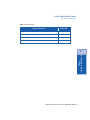
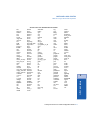
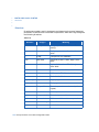
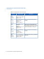
The following table lists reserved elements that are updated by the Event and
Interval Timer task.
While the Timer task is running, these reserved elements are constantly updated.
In order for the Timer task to run, you must have entered an R flag for the Timer
task in the System Configuration Table in the Configuration Manager Main
Menu.
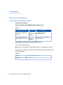
Table 2-1
Reserved Element
Data Type
A_SEC
Analog
A_MIN
Analog
A_HOUR
Analog
A_DAY (Day of month)
Analog
A_MONTH
Analog
A_YEAR
Analog
A_DOW (Day of week)
Analog
A_DOY (Day of year)
Analog
DATE (DOW MM-DD-YYYY)
Message
TIME (HH:MM:SS)
Message
DATETIME (DOW MM-DD-YYYY HH:MM:SS)
Message
38 / FactoryLink ECS / Core Tasks Configuration Guide
EVENT AND INTERVAL TIMER
Principles of Operation
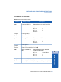
Table 2-1 (Continued)
Reserved Element
Data Type
YYMMDD (YY-MM-DD)
Message
SECDAY (Seconds since start of current day)
Long Analog
SECYEAR (Seconds since start of current year)
Long Analog
SECTIME (Seconds since January 1, 1980)
Long Analog
2
Event and Interval
Timer
FactoryLink ECS / Core Tasks Configuration Guide / 39
•
•
•
•
EVENT AND INTERVAL TIMER
Changing the Operating System Date and Time
C HAN GIN G
THE
O PER ATING S YSTEM D ATE
A ND
T IM E
To change the operating system date and time while FactoryLink is running, shut
down the Timer task, change the date and time, and restart the task. Otherwise,
the Timer task tries to catch up by processing missed intervals.
C ON FIGUR ING
THE
E VENT
AND I NTERV AL
T IMER T A SK
Use this task to signal the occurrence of specified events or intervals by writing to
digital elements in the FactoryLink real-time database.
The Event and Interval Timer task uses the SHARED domain. Before opening
and configuring the Event and Interval Timer task, ensure the current domain
selected is SHARED in the Configuration Manager Domain Selection box.
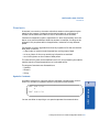
Event Timer Information Dialog
Use Event Timer to define events that only occur not more than once every 24
hours. For example, use event timers to start or stop reports, and as triggers to
read and write recipe files.
Choose Event Timer to display the Event Timer Information dialog.
40 / FactoryLink ECS / Core Tasks Configuration Guide
EVENT AND INTERVAL TIMER
Configuring the Event and Interval Timer Task
Following are field descriptions for this dialog.
Tag Name
Element name (for example, time8am) to be assigned to the
event. When the event occurs, the element is forced to 1 so its
change-status bit is set to 1. The Timer task resets all event
timers back to zero at midnight. You can assign more than one
element to the same event.
If the tag specified in this field is not already defined, a Tag
Definition dialog is displayed when you click on Enter with a tag type
of digital in the Type field. Accept this default.
Valid Entry: standard element tag name
Valid Data Type: digital (default = digital)
Year, Mon. Day
DOW
Specify a period when an event is to occur. Enter a Year (Year)
month (Mon) day (Day) and day-of-the-week (DOW) or
combination as explained below.
When using DOW, if you enter a month, the event occurs on this
day every week of that month only. If you do not enter a month,
the event occurs on this day every week. If you enter a month and
year, the event occurs on this day every week of the specified
month during the specified year. If you do not enter a month and
year, the event occurs on this day every week of every year.
Year 4-digit year such as 1994.
Month 1-12 or MMM (Example: March is 3 or MAR for
first three letters of the month’s name.)
Day 1-31 indicating the day of the month the event is to
occur. If the event is to occur once every day, leave
this field blank.
DOW MON - SUN First three letters of a weekday. If the
event is to occur once every day, leave the field
blank.
Hours Refer to the following discussion of Hours, Mins.,
and Secs.
FactoryLink ECS / Core Tasks Configuration Guide / 41
2
Event and Interval
Timer
When using Day and Month, the event occurs only on this date in
the specified month in the specified year. If you do not enter a
month, the event occurs on this date every month. If you do not
enter a month and year, the event occurs on this date every
month of every year.
•
•
•
•
EVENT AND INTERVAL TIMER
Configuring the Event and Interval Timer Task
Mins. Refer to the discussion of Hours, Mins., and Secs.
that follows.
Hours, Mins. Secs.
Hours, Mins. (minutes), and Secs. (seconds) fields define the
specific time (in 24-hour format) at which an event is to occur.
The event timer assumes a default value of 0 for blank fields. The
conventions for use are:
Hours Hour the event is to occur (0 to 23).
Mins. Number of minutes (0 to 59) after the hour the
event is to occur. If the event is to occur on the
hour, leave this field blank.
Secs. Number of seconds (0 to 59) after the minute (or
hour) the event is to occur.
Between midnight (00:00:00) and the time indicated in the Hours,
Mins., and Secs. fields, the value of the element to which an event
is linked is 0 (OFF). After the timed event occurs, the element’s
value changes to 1 (ON) and stays this way until midnight, when
it changes back to 0 (OFF).
Hours 0 - 23 (0 is midnight and 23 is 11:00 pm.)
Mins. 0 - 59
Secs. 0 - 59
First
Value that determines the action taken upon system startup, if
startup occurs after a timed event. Because this field only affects
events scheduled for the current date, the system checks the date
before changing any values.
Yes The element’s value immediately changes to 1
(ON), indicating the timed event has occurred for
that date. The change-status flags are also set to 1
(ON).
No Default—the element’s value is left “as is” and
does not change to 1 (ON) until the next
occurrence of the timed event.
42 / FactoryLink ECS / Core Tasks Configuration Guide
EVENT AND INTERVAL TIMER
Configuring the Event and Interval Timer Task
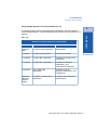
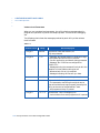
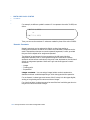
When all information has been specified, the dialog resembles the sample dialog
below:
In this example, the startday element has a value of 0 between midnight and 8:00
am and 1 between 8:00 am and 11:59 pm and 59 seconds (23.59.59) each day of the
year.
The newyear element’s value has a value of 1 on January 1 of each year and 0 on
all other days.
Similarly, the lastday element’s value has a value of 1 on December 31 of each
year and 0 on all other days.
The fri5pm element has a value of 1 each Friday between 5:00 pm and midnight.
Click Enter to save the information and return to the Main Menu when you finish
setting the event timers.
Interval Timer Information Dialog
Use Interval Timer to define events that occur at least once every 24 hours at
regular intervals of the system clock, such as every second or every two hours. For
example, use interval timers as triggers in Polled Read or Write PLC tables and in
Send or Receive tables for FL/LAN Network configurations.
FactoryLink ECS / Core Tasks Configuration Guide / 43
Event and Interval
Timer
Similarly, the endday element has a value of 0 between midnight and 5:00 pm and
1 between 5:00 pm and 11:59 pm and 59 seconds.
2
•
•
•
•
EVENT AND INTERVAL TIMER
Configuring the Event and Interval Timer Task
Choose Interval Timer to display the Interval Timer Information dialog.
Following are field descriptions for this dialog.
Tag Name
Name of the element (for example, sec5) to be assigned to the
interval. You can assign the same interval to more than one
element.
If the tag specified in this field is not already defined, a Tag
Definition dialog is displayed when you click on Enter with a tag type
of digital in the Type field. Accept this default.
Valid Entry: standard element tag name
Valid Data Type: digital (default = digital)
Hours Mins. Secs.
10ths
Hours, Mins. (minutes), Secs. (seconds), and 10ths (tenths of a
second) fields define the interval at which an event is to occur. If
these fields are left blank, the interval timer assumes a default
value of 0. At least one of these fields must be filled in with a
valid entry (not zero, as it is not considered a valid entry) or else
the system does not allow the ITimer to start, but instead
displays the error message:
“Bad data in ITimer record (record#), file (itimer.exe).”
Depending on the interval you specify, the timer starts at
midnight or at system startup. If the interval can be divided
evenly into 24 hours (86,400 seconds, or 1,440 minutes), the timer
runs as if it started at midnight. If the interval cannot be evenly
divided into 24 hours, the timer starts at system startup.
Conventions for use:
Hours A number between 0 and 23 that indicates the
length, in hours, of the interval. Example: Every 2
hours (2), every 3 hours (3), etc.
44 / FactoryLink ECS / Core Tasks Configuration Guide
EVENT AND INTERVAL TIMER
Configuring the Event and Interval Timer Task
Mins A number between 0 and 59 that indicates the
length, in minutes, of the interval. Example: Every
5 minutes (5), every 10 minutes (10), etc.
Secs A number between 0 and 59 that indicates the
length, in seconds, of the interval. Example: Every
second (1), every 7 seconds (7), etc.
10ths A number between 0 and 9 that indicates the
length, in tenths of a second, of the interval.
Example: Every tenth of a second (1), every half
second (5), etc.
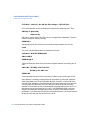
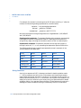
When all information has been specified, the Interval Timer Information dialog
resembles the sample dialog below:
2
The sec30 element’s change-status flags are set to 1 every 30 seconds, when
A_SEC = 0 and 30. This timer runs as if it started at midnight.
The min7 element’s change-status flags are set to 1 every 7 minutes after system
startup, because 1,440 is not evenly divisible by 7.
The min20 element’s change-status flags are set to 1 every hour, again at 20
minutes after the hour, and again at 40 minutes after the hour.
FactoryLink ECS / Core Tasks Configuration Guide / 45
Event and Interval
Timer
In this example, the sec5 element’s change-status flags are set to 1 every 5
seconds; that is, when the reserved analog element A_SEC = 0, 5, 10, 15, ... 55.
This timer runs as if it started at midnight. Therefore, if system startup time is
9:39:18, the sec5 element’s change-status flags are first set 2 seconds later, at
9:39:20, and every 5 seconds thereafter.
•
•
•
•
EVENT AND INTERVAL TIMER
Configuring the Event and Interval Timer Task
The report1 element’s change-status flags are set to 1 every hour and 17 minutes,
after system startup.
The hour8 element’s change-status flags are set to 1 three times a day: at 8:00 am,
4:00 pm, and midnight, regardless of system startup time.
When interval timers are used as triggers for other tasks, such as PLC read
triggers or Report Generator triggers, these tasks automatically use the
change-status flags associated with these timers.
46 / FactoryLink ECS / Core Tasks Configuration Guide
Core Tasks Configuration Guide
•
•
•
•
•
•
•
•
•
•
•
•
•
•
•
•
•
•
•
•
•
•
•
•
•
•
•
•
•
•
Part III
Programmable Counters
Table of Contents
•
•
•
•
Programmable Counters in the Core Tasks Con- Programmable Counters in this book
figuration Guide
Programmable Counters
3
Programmable Counters . . . . . . . . . . . . . . . . . . . . . . . . . . . . . . . . . . . . 51
Principles of Operation . . . . . . . . . . . . . . . . . . . . . . . . . . . . . . . . . . . . . . . . . .
Elements . . . . . . . . . . . . . . . . . . . . . . . . . . . . . . . . . . . . . . . . . . . . . . . . .
Digital and Analog Values . . . . . . . . . . . . . . . . . . . . . . . . . . . . . . . . . . .
Example One . . . . . . . . . . . . . . . . . . . . . . . . . . . . . . . . . . . . . . . . . . . . . .
Example Two . . . . . . . . . . . . . . . . . . . . . . . . . . . . . . . . . . . . . . . . . . . . . .
Programmable Counters Information Panel . . . . . . . . . . . . . . . . . . . . . . . . .
52
52
52
53
53
55
FactoryLink ECS / Core Tasks Configuration Guide / 49
•
•
•
•
Programmable Counters
50 / FactoryLink ECS / Core Tasks Configuration Guide
•
•
•
•
Chapter 3
Programmable
Counters
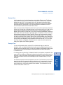
Use the Programmable Counters task to provide count-per-unit-of-time
measurements and to provide event delays, such as defining a trigger to unlock a
door and then specifying a delay before the door locks again.
A programmable counter is a group of elements with values that work together to
perform a count. Outputs from programmable counters can be used to provide
input to Math and Logic programs or other FactoryLink tasks or to trigger Math
and Logic programs.
There is no limit, except the amount of memory, to the number of programmable
counters that can be defined.
The Programmable Counters task uses either the SHARED or USER domain.
The use of programmable counters requires an understanding of change-status
flags. Refer to FactoryLink Fundamentals for this discussion.
3
Programmable
Counters
FactoryLink ECS / Core Tasks Configuration Guide / 51
•
•
•
•
PROGRAMMABLE COUNTERS
Principles of Operation
PR INCIP LES
OF
O PER ATION
A programmable counter is a group of elements with components that work
together to perform a count. Each programmable counter is made up of some or all
of the following elements and analog and digital values.
Elements
• Enable—triggers counting activity.
• Up Clock—initiates the count upward.
• Down Clock— initiates the count downward.
• Clear—resets the counted value to the starting point.
• Positive Output—contains the value 1 (on) when the counting limit has been
reached.
• Negative Output—contains the value 0 (off) when the counting limit has been
reached.
• Current Value—indicates the current value of the count.
Digital and Analog Values
• Preset Value—analog value that specifies the starting value.
• Increment Value—analog value that specifies the amount by which the count
is to increase or decrease each time.
• Terminal Value—analog value that specifies the counting limit.
• AutoClear—digital value that resets the count to the starting point whenever
the terminal value is reached.
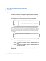
Counting begins when another FactoryLink task, such as Math and Logic or EDI,
writes a 1 (ON) to the Up Clock element. This triggers the Programmable
Counters task to move the Current Value toward the Terminal Value by the
Increment Value. If the Preset Value is less than the Terminal Value, the
Increment is added to the Current Value. If the Preset Value is more than the
Terminal Value, the Increment is subtracted from the Current Value.
52 / FactoryLink ECS / Core Tasks Configuration Guide
PROGRAMMABLE COUNTERS
Principles of Operation
Example One
In this example, counting is triggered to count bottles (20 per case). The Preset
Value (start count) is 0, and the Terminal Value (count limit) for the number of
bottles per case is 20. The Increment Value of 1 represents one bottle. When
counting is triggered, each bottle counted increases the current count of bottles
(starting with 0 in the case) by 1 until the case contains 20 bottles (until the
Current Value reaches the Terminal Value of 20).
When the case contains 20 bottles (when the Current Value reaches the Terminal
Value), the Counter task indicates the case is full by force-writing a 1 (ON) to the
Positive Output element and force-writing a 0 (OFF) to the Negative Output
element. At this point, if AutoClear = YES, the Current Value element is reset to 0
(the Preset Value), and the count can begin again. If AutoClear = NO, the current
Value element remains at 20 (the Terminal Value), until another task writes a 1
(ON) to the clear element, indicating the count can begin again. The count does
not continue past 20 (the Terminal Value). Each time the bottle count reaches 20
(the Terminal Value), the Counter task again force-writes a 1 (ON) and a 0 (OFF)
to the Positive and Negative Output elements. When AutoClear = YES, or when
the Clear element is triggered, the bottle count is reset to 0 (the Preset Value),
ready for a repeat of the counting process.
Example Two
You can set up another task, such as EDI or Math and Logic, to react to a
deviation (such as a defective bottle) during the count by adjusting the count. To
adjust the count, that task writes a 1 (ON) to the Down Clock element to cause the
value of the Current Value element to move toward the Preset Value by the
Increment Value.
Six bottles have been counted and packed in the case. The Counter task counts the
seventh bottle. But the seventh bottle is defective, so it is not packed in the case.
Therefore, the EDI or Math and Logic task subtracts that bottle from the total
count by writing a 1 (ON) to the Down Clock element. This causes the Current
Value to move from 7 down to 6.
FactoryLink ECS / Core Tasks Configuration Guide / 53
3
Programmable
Counters
For example, during counting, if a defective bottle is counted but not packed in the
case, the EDI or Math and Logic task subtracts that bottle from the total count by
writing a 1 (ON) to the Down Clock element to cause the Current Value to move
toward the Preset Value (0 in this example) by the Increment Value (1 in this
example).
•
•
•
•
PROGRAMMABLE COUNTERS
Principles of Operation
If all counted bottles are defective and thus are not packed, the EDI or Math and
Logic task subtracts them from the total count by causing the Current Value to
count down until it matches the Preset Value (0). Although the bottle count is now
0, the Output elements have not been affected and the current counting operation
continues until the case contains 20 bottles.
54 / FactoryLink ECS / Core Tasks Configuration Guide
PROGRAMMABLE COUNTERS
Programmable Counters Information Panel
PRO GR AM MAB LE C O UN TERS IN FO RM ATIO N PAN EL
The Programmable Counters task establishes parameters for the initiation,
performance, and conclusion of counting activity.
The Programmable Counters task uses either the SHARED or the USER domain.
We recommend the SHARED domain, unless counters should be unique to each
User for the purposes of the application. Before opening and configuring the
Programmable Counters task, ensure the current domain selected is SHARED in
the Configuration Manager Domain Selection box.
With the “-t” program argument in the System Configuration in effect for the
counter task, negative output, positive output, and current value are initialized.
Positive output is set to 0. Negative output is set to 1. With no program argument,
those tags remain at their default/persistent values.
Choose Programmable Counters to display the Programmable Counters
Information panel. This panel contains eleven fields. Press Tab to display other
fields.
3
Enable
Name of an element that enables or triggers counting. If this field
is left blank, counting is always enabled because the trigger
becomes either the “UP CLOCK” or the “DOWN CLOCK”. When
the value of Enable is set to 1 (ON), counting occurs. If the value
of Enable is set to 0 (OFF), counting does not occur.
FactoryLink ECS / Core Tasks Configuration Guide / 55
Programmable
Counters
Following are field descriptions for this panel.
•
•
•
•
PROGRAMMABLE COUNTERS
Programmable Counters Information Panel
If the tag specified in this field is not already defined, a Tag
Definition panel is displayed when you click on Enter with a tag
type of digital in the Type field. Accept this default.
Valid Entry: standard element tag name
Valid Data Type: digital
Up Clock
Name of an element that causes the value of the Current Value
element (present count) to move toward the Terminal Value
(count limit). When a 1 (ON) is written to the Up Clock element,
the value in the Current Value element is increased by the
amount specified by the Increment Value element, described
below. If the Preset Value (starting count) is less than the
Terminal Value, the Increment Value is added to the Current
Value. If the Preset Value is greater than the Terminal Value, the
Increment Value is subtracted from the Current Value.
If the tag specified in this field is not already defined, a Tag
Definition dialog is displayed when you click on Enter with a tag
type of digital in the Type field. Accept this default.
At least one type of clock must be defined; that is, an entry is
required in either the Up Clock or Down Clock field.
Valid Entry: standard element tag name
Valid Data Type: digital
Down Clock
Name of an element that causes the value of the Current Value
element (present value) to move away from the Terminal Value
(toward the Preset Value). When a 1 (ON) is written to the Down
Clock element, the value in the Current Value element is
decreased by the amount specified by the Increment Value
element. If the Preset Value is less than the Terminal Value, the
Increment Value is subtracted from the Current Value. If the
Preset Value is greater than the Terminal Value, the Increment
is added to the Current Value. The Current Value does not move
past the Preset Value and the Positive/Negative Outputs are not
triggered when the Preset Value is reached. The data type for this
tag is digital.
At least one type of clock must be defined; that is, an entry is
required in either the Up Clock or Down Clock field.
Valid Entry: standard element tag name
Valid Data Type: digital
56 / FactoryLink ECS / Core Tasks Configuration Guide
PROGRAMMABLE COUNTERS
Programmable Counters Information Panel
Clear
Name of an element that causes the Current Value to be reset to
the Preset Value each time a 1 (ON) is written to it (the Clear
element). Each time a 1 (ON) is force-written to the Clear
element, a 0 (OFF) is force-written to the Positive Output
element and a 1 (ON) is written to the Negative Output element.
If the tag specified in this field is not already defined, a Tag
Definition dialog is displayed when you click on Enter with a tag
type of digital in the Type field. Accept this default.
Valid Entry: standard element tag name
Valid Data Type: digital
Positive Output
Name of an element to which a 1 (ON) is written each time the
Current Value reaches the Terminal Value. The value of the
Positive Output element remains 1 (ON) until a 1 (ON) is written
to the Clear element.
If the tag specified in this field is not already defined, a Tag
Definition dialog is displayed when you click on Enter with a tag
type of digital in the Type field. Accept this default.
Valid Entry: standard element tag name
Valid Data Type: digital
Negative Output
Name of an element to which a 0 (OFF) is written each time the
Current Value reaches the Terminal Value. The value of the
Negative Output element remains 0 (OFF) until a 1 (ON) is
written to the Clear element. This tag is set to 1 at task startup.
If the tag specified in this field is not already defined, a Tag
Definition dialog is displayed when you click on Enter with a tag
type of digital in the Type field. Accept this default.
Valid Entry: standard element tag name
Valid Data Type: digital
Current Value
If the tag specified in this field is not already defined, a Tag
Definition dialog is displayed when you click on Enter with a tag
type of analog in the Type field. Accept this default.
Valid Entry: standard element tag name
Valid Data Type: analog, longana
FactoryLink ECS / Core Tasks Configuration Guide / 57
Programmable
Counters
Name of an element to specify the name of an element that
contains the current value of the counter. This value is always
between the Preset Value and the Terminal Value.
The default is 0.
3
•
•
•
•
PROGRAMMABLE COUNTERS
Programmable Counters Information Panel
Preset Value
Enter a number between -32,768 and 32,767 to specify the
starting value for a count. This numerical value is written to the
Current Value element whenever the value of the Clear element
is set to 1 (ON). The default is 0.
Valid Entry: numeric value between -32,768 and 32,767
(default = 0)
Increment Value
Enter a number between 0 and 32,767 to specify the numerical
value that is combined with the Current Value when the Up or
Down Clock is triggered. The default is 1.
Valid Entry: numeric value between 0 and 32,767 (default = 1)
Terminal Value
Enter a number between -32,768 and 32,767 to define the
numerical value that specifies a limit for counting activity. When
the Current Value is the same as the Terminal Value, counting
stops and Positive and Negative Outputs are triggered. Counting
remains stopped until the Clear element is triggered. However, if
AutoClear is set, a Clear is performed immediately after the
Positive and Negative Outputs are triggered.
Valid Entry: numeric value between -32,768 and 32,767
Autoclear
Indicator that a Clear should be performed each time the
Terminal Value is reached. This can be one of the following:
YES Clear is performed each time the Terminal Value
is reached. This is the default.
NO Current Value remains equal to the Terminal
Value until Clear is triggered.
58 / FactoryLink ECS / Core Tasks Configuration Guide
PROGRAMMABLE COUNTERS
Programmable Counters Information Panel
When all information has been specified, the panel should resemble the sample
below:
3
FactoryLink ECS / Core Tasks Configuration Guide / 59
Programmable
Counters
In the first example (first line on the panel), the counter, along with a Math and
Logic procedure that saves the count and resets the counter, counts the number of
bottles packed per minute. Since the Enable field is left blank, counting is always
enabled. Each time a bottle is packed, a 1 (ON) is written to the Up Clock element
btl_upclock. This triggers the Counter task to increase the Current Value
(btl_count) by 1. Each minute, FactoryLink triggers a Math and Logic procedure
to log the Current Value and trigger the Clear element (btl_clear) to reset the
count for the next minute.
•
•
•
•
PROGRAMMABLE COUNTERS
Programmable Counters Information Panel
In the second example (second line on the panel), the counter is used to create a
one-minute delay of an event, such as bottle capping. Since the Enable field is left
blank, counting is always enabled. When the value of sec1 becomes 1 (ON), the
Counter task increases the Current Value (min_delay) by 1. The task continues to
increase this value once each second until the Current Value matches the
Terminal Value of 60. At this time, counting stops and the Counter task writes a 1
(ON) to the Positive Output element min_end, indicating the end of the
one-minute delay. Other FactoryLink tasks can monitor the min_end element to
trigger another operation and then write a 1 (ON) to the Clear element
(min_start) to reset the count.
60 / FactoryLink ECS / Core Tasks Configuration Guide
Core Tasks Configuration Guide
•
•
•
•
•
•
•
•
•
•
•
•
•
•
•
•
•
•
•
•
•
•
•
•
•
•
•
•
•
•
Part IV
File Manager
Table of Contents
•
•
•
•
File Manager in the Core Tasks Configuration File Manager in this book
Guide
File Manager
4
File Manager . . . . . . . . . . . . . . . . . . . . . . . . . . . . . . . . . . . . . . . . . . . . . . . 65
File Manager Control Panel . . . . . . . . . . . . . . . . . . . . . . . . . . . . . . . . . . . . . .
File Manager Information Panel . . . . . . . . . . . . . . . . . . . . . . . . . . . . . . . . . .
Sample File Manager Operations. . . . . . . . . . . . . . . . . . . . . . . . . . . . . . . . . .
Example 1: COPY . . . . . . . . . . . . . . . . . . . . . . . . . . . . . . . . . . . . . . . . . .
Example 2: PRINT. . . . . . . . . . . . . . . . . . . . . . . . . . . . . . . . . . . . . . . . . .
Example 3: REN (Rename) . . . . . . . . . . . . . . . . . . . . . . . . . . . . . . . . . . .
Example 4: TYPE. . . . . . . . . . . . . . . . . . . . . . . . . . . . . . . . . . . . . . . . . . .
Example 5: DIR (Directory) . . . . . . . . . . . . . . . . . . . . . . . . . . . . . . . . . .
Example 6: DEL (Delete) . . . . . . . . . . . . . . . . . . . . . . . . . . . . . . . . . . . . .
Using Variable Specifiers in File Specifications . . . . . . . . . . . . . . . . . . . . . .
Using Wildcard Characters in File Specifications. . . . . . . . . . . . . . . . . . . . .
Using the File Manager with Networks. . . . . . . . . . . . . . . . . . . . . . . . . . . . .
Using the COPY Command with FLLAN . . . . . . . . . . . . . . . . . . . . . . . .
Using the COPY Command with a Network without FLLAN . . . . . . . . .
Technical Notes . . . . . . . . . . . . . . . . . . . . . . . . . . . . . . . . . . . . . . . . . . . . . . . .
Operating System Notes . . . . . . . . . . . . . . . . . . . . . . . . . . . . . . . . . . . . . . . . .
For Windows NT and Windows 95 Users . . . . . . . . . . . . . . . . . . . . . . . .
For OS/2 Users . . . . . . . . . . . . . . . . . . . . . . . . . . . . . . . . . . . . . . . . . . . .
For Unix Users. . . . . . . . . . . . . . . . . . . . . . . . . . . . . . . . . . . . . . . . . . . . .
66
74
76
76
79
80
81
82
84
85
87
88
89
92
93
94
94
96
98
FactoryLink ECS / Core Tasks Configuration Guide / 63
•
•
•
•
File Manager
64 / FactoryLink ECS / Core Tasks Configuration Guide
•
•
•
•
Chapter 4
File Manager
4
File Manager initiates these operations with six commands: COPY, REN, DEL,
PRINT, DIR, and TYPE. These commands perform the same functions as their
operating-system counterparts. The File Manager controls all file operations
through the FactoryLink real-time database.
You can configure other FactoryLink tasks to initiate File Manager operations.
For example:
• You can configure input functions in Graphics so an operator can use them to
initiate file-management operations at run time, such as to display a list of
recipes or reports.
• The Timer task can trigger File Manager to automatically back up files to a
networked server at certain intervals, such as each day at midnight.
• The Timer task can also trigger File Manager to delete log files automatically at
certain intervals, such as once every four hours, or after certain events, such as
when log files reach a specified size.
• Alarm Supervisor can trigger File Manager to print alarm files.
FactoryLink ECS / Core Tasks Configuration Guide / 65
File Manager
The FactoryLink File Manager task can be used to perform basic operating
system file-management operations initiated by a FactoryLink application at run
time. The task can work in conjunction with FactoryLink’s FLLAN option to
initiate operations within other FactoryLink stations on a network. The File
Manager initiates the operations listed below which are performed by the
operating system.
• Copy a file
• Rename a file
• Delete a file
• Print a file
• Display a directory
• Type a file
•
•
•
•
FILE MANAGER
File Manager Control Panel
F ILE M ANAG ER C ON TRO L P ANEL
The File Manager Table has two panels.
• File Manager Control (configure one)
• File Manager Information
All operations are defined in one File Manager Control panel. For COPY, REN,
DEL, and PRINT operations, do not complete a File Manager Information panel.
However, for each TYPE or DIR operation defined in the File Manager Control
panel, complete one File Manager Information panel.
File Manager defaults to the USER domain, but you can configure it to run in
either domain. Before opening and configuring File Manager, ensure the domain
selected is the correct one in the Configuration Manager Domain Selection box.
Choose File Manager to display the File Manager Control and File Manager
Information panels. Complete the File Manager Control panel first:
Following are field descriptions for this panel.
Table Name
(Required for TYPE and DIR operations) Enter an alphanumeric
string of between 1 to 16 characters that specifies the name of the
operation being defined or modified. For TYPE and DIR
operations, this field connects the entry in the File Manager
Control panel with the associated File Manager Information
panel for that entry.
This field is optional for COPY, REN, DEL, and PRINT
operations. You can use it to distinguish different operations of
the same type.
Valid Entry: alphanumeric string of between 1 to 16
characters
66 / FactoryLink ECS / Core Tasks Configuration Guide
FILE MANAGER
File Manager Control Panel
Command Trigger
Name of an element used to initiate the file operation.
If the tag specified in this field is not already defined, a Tag
Definition dialog is displayed when you click on Enter .
Position Trigger
Required only for DIR and TYPE operations; not used for COPY,
PRINT, REN, and DEL operations. Name of an element whose
value tells the File Manager where in a directory to start listing
files, or where in a file to start typing.
The File Manager starts reading after the line number specified
by the value of the Position Trigger element. For example, if the
value of the Position Trigger element is 6, the File Manager
begins reading the file at line seven. The number of lines
displayed or the number of files listed depends on the number of
Tag Name elements defined in the File Manager Information
panel, described below.
You can configure the system so, at run time, you or any
FactoryLink task can change the value of this element so the File
Manager starts at a different point in a directory or file and
shows a different subset of information.
Do not specify the same element name for DIR and TYPE
operations. If the tag specified in this field is not already defined,
a Tag Definition dialog is displayed when you click on Enter. Accept
this default.
Valid Entry: standard element tag name
Valid Data Type: analog
Command
File operation to be performed. This can be one of the following.
COPY Copies the source file to the destination file.
Specify both the source and destination paths.
This operation does not require that you complete
a File Manager Information panel.
REN Renames the source file to the destination file.
Specify both the source and destination paths.
Both the source and destination paths must be the
same; that is, they must point to the same
directory. This operation does not require you
complete a File Manager Information panel.
FactoryLink ECS / Core Tasks Configuration Guide / 67
File Manager
Valid Entry: standard element tag name
Valid Data Type: digital, analog, longana, float, message
4
•
•
•
•
FILE MANAGER
File Manager Control Panel
DEL Deletes the source file. The DEL command
requires only the source path; the destination path
is ignored. This operation does not require you
complete a File Manager Information panel.
PRINT Causes the file specified by the source path to be
printed on the device specified by the destination
path. The destination path must contain the name
of a device known to the Print Spooler task. This
operation works only with the Print Spooler and
does not require that you complete a File Manager
Information panel.
DIR Displays a list of all files in the directory specified
by the source path, which can include wildcard
characters. The destination path is ignored. This
operation requires you complete a File Manager
Information panel and you define output text
objects in Graphics to display lines from the file.
TYPE Displays the contents of the source file. The
destination path is ignored. This operation
requires that you complete a File Manager
Information panel and that you define output text
objects in Graphics to display lines from the file.
Note that File Manager reads in only 80
characters at a time, and puts the rest of the line
(if more than 80 characters) into the next message
tag. For example, if the message in the line is 140
characters long, it puts the first 80 into the first
message tag, and the next 60 into the second
message tag.
68 / FactoryLink ECS / Core Tasks Configuration Guide
FILE MANAGER
File Manager Control Panel
Source File Spec.
Full path name of the source file. The source file spec. can use the
filename syntax for the operating system on which either the
remote or the local station resides. If you are using FLLAN, the
source can reference a remote station.
Type wildcard characters in the path name to show a root
directory’s contents using the DIR command. For example, in
this field type:
C:\*.*
Only one file in a copy operation can be remote. Both files in a
rename operation must be on the same station.
For stand-alone systems:
/DEVICE_NAME/DIR_NAME/SUB_DIR_NAME/FILE_NAME
For networked systems:
\\STATION_NAME\DEVICE_NAME/DIR_NAME/SUB_DIR_NAME/FILE
_NAME
In the case of the COPY, DEL, and DIR commands, the source file specification
may contain variable specifiers or wildcard characters (“*”). Refer to “Using
Variable Specifiers in File Specifications” on page 85 and “Using Wildcard
Characters in File Specifications” on page 87 for more information about variable
specifiers and wildcard characters.
Valid Entry: full path name
FactoryLink ECS / Core Tasks Configuration Guide / 69
File Manager
If you specify a remote station for the destination and a remote
station for the source, the two remote stations must be the same.
If the destination is local, there is no restriction on the source
station. Similarly, if the source is local, there is no restriction on
the destination. Refer to “Using the File Manager with Networks”
on page 88 for information about referencing remote stations.
4
•
•
•
•
FILE MANAGER
File Manager Control Panel
Source Variables
1-4
Names of elements whose values replace the variable specifiers in
the source path name. These fields work in conjunction with the
Source File Spec. field to form the path of the file to which the File
Manager performs operations. The value of the element in the
Source Variable 1 field replaces the first variable specifier, the
value of the element in the Source Variable 2 field replaces the
second variable specifier, and so on.
If the tag specified in this field is not already defined, a Tag
Definition dialog is displayed when you click on Enter .
If using variable specifiers, make the data type of the element
match the variable specifier type. Refer to FactoryLink
Fundamentals for information about variable specifiers.
Valid Entry: standard element tag name
Valid Data Type: digital, analog, longana, float, message
Destination File
Spec.
Full path name of the destination file. The destination file spec.
can use the filename syntax for the operating system on which
either the remote or the local station resides. If you are using
FLLAN, the destination can reference a remote station.
If you specify a remote station for the destination and a remote
station for the source, the two remote stations must be the same.
If the destination is local, there is no restriction on the source
station. Similarly, if the source is local, there is no restriction on
the destination. Refer to “Using the File Manager with Networks”
on page 88 for information about referencing remote stations.
For stand-alone systems:
/DEVICE_NAME/DIR_NAME/SUB_DIR_NAME/FILE_NAME
For networked systems:
\\STATION_NAME\DEVICE_NAME/DIR_NAME/SUB_DIR_NAME/FILE
_NAME
Unless you use wildcard characters in the source file spec.,
specify the full path name of the destination. If you use wildcard
characters, do not specify the full path; specify only the directory.
Refer to FactoryLink Fundamentals for information about
wildcard characters.
In the case of the COPY, DEL, and DIR commands, the
destination file specification can contain variable specifiers or
wildcard characters (“*”). Refer to FactoryLink Fundamentals for
information about variable specifiers.
70 / FactoryLink ECS / Core Tasks Configuration Guide
FILE MANAGER
File Manager Control Panel
If using the PRINT command, use the following destination file
spec. format:
4
[\\station_name\] [flags] [spool_device]
where
flags are the optional flags. This can be one of the
following.
NONE—This is the default.
B—Binary file
S—Suppress Beginning and End of File. Used to
concatenate files
spool_device is the optional spool device (defaults to 1; legal
devices are 1 through 5).
Destination
Variables 1-4
Names of elements whose values replace the variable specifiers in
the destination path name. These fields work in conjunction with
the Destination Format field to form the path of the file to which the
File Manager performs operations. The value of the element in
the Destination Variable 1 field replaces the first variable specifier,
the value of the element in the Destination Variable 2 field replaces
the second variable specifier, and so on.
If the tag specified in this field is not already defined, a Tag
Definition dialog is displayed when you click on Enter.
If you use variable specifiers, make the data type match the
variable specifier type. Refer to FactoryLink Fundamentals for
information.
Valid Entry: standard element tag name
Valid Data Type: digital, analog, longana, float, message
Completion Trigger
Name of an element used to indicate that a file-management
operation is complete (not necessarily successful). This element, if
entered, is set by File Manager and can be referenced by any
FactoryLink task (including File Manager) to monitor
file-management operations or trigger an event.
FactoryLink ECS / Core Tasks Configuration Guide / 71
File Manager
station_name is the optional FactoryLink station name
(defaults to LOCAL). The FactoryLink station
name is not used on stand-alone systems.
•
•
•
•
FILE MANAGER
File Manager Control Panel
If the tag specified in this field is not already defined, a Tag
Definition dialog is displayed when you click on Enter with a tag
type of digital in the Type field. Accept this default.
Valid Entry: standard element tag name
Valid Data Type: digital
Completion Status
Name of an element set by the File Manager task to indicate the
status of an operation. The Completion Status element can be
referenced by any FactoryLink task (including the File Manager)
to handle file error situations or trigger the next File Manager
table to start an operation.
If the tag specified in this field is not already defined, a Tag
Definition dialog is displayed when you click on Enter with a tag
type of analog in the Type field. Accept this default.
The File Manager writes an analog value to the Completion
Status element to indicate the status of a file management
operation.
Use the task’s TASKMESSAGE_U[6] tag to report messages on
the application screen in addition to the Completion Status tag.
For example, if you get a status 12 in the Completion Status tag,
you also see the message: “Can’t open file (path/filename)” in the
tag TASKMESSAGE_U[6].
If you want to use IML for this function, set up a math procedure
triggered by the status tag itself. In the procedure, assign the
appropriate ASCII string for each possible status code to a
message tag in a series of IF THEN statements. For example:
IF status = 1 THEN
MSG = “whatever”
ENDIF
72 / FactoryLink ECS / Core Tasks Configuration Guide
FILE MANAGER
File Manager Control Panel
This element can have any of the following status values:
4
Table 4-1
Value
Description
Value
Description
Operation completed
successfully
12
Can’t open file
(path/filename)
1
Current operation in
progress
13
Error occurred while
reading a file
2
Specified file(s) not found
14
File could not be created
*3
Requested a line beyond end
of file
15
Error occurred while
writing to a file
5
Remote system could not
perform requested action
16
Illegal spool device was
specified
6
Attempt to log onto a remote 17
station failed
Not enough memory to
perform operation
8
Network transmission error
occurred
Illegal filename was
specified
97
* If the TYPE/DIR position trigger offset values are increased
beyond the end of the file, the File Manager will read in as
many lines as possible, set the completion trigger, and set the
completion status to 3.
Refer to “Sample File Manager Operations” on page 76 for examples of File
Manager operations.
Valid Entry: standard element tag name
Valid Data Type: analog
FactoryLink ECS / Core Tasks Configuration Guide / 73
File Manager
0
•
•
•
•
FILE MANAGER
File Manager Information Panel
F ILE M ANAG ER IN FOR MATIO N PA NEL
Click Enter to save the information after completing the File Manager Control
panel. Then, click Next to display the File Manager Information panel.
Following are field descriptions for this panel.
Tag Name
(Required only for DIR and TYPE operations; not used with
COPY, PRINT, REN, and DEL operations) Name of a message
element that, as a result of a DIR or TYPE command, receives a
message value to be displayed in a single line on a graphics
screen. The number of Tag Name fields defined in this panel
determines the number of lines displayed as a result of a DIR or
TYPE command at run time.
If the tag specified in this field is not already defined, a Tag
Definition dialog is displayed when you click on Enter with a tag
type of message in the Type field. Accept this default.
Values are written to the elements defined in the Tag Name field
whenever a DIR or TYPE operation is triggered, or whenever the
operator changes the value of the Position Trigger element
defined in the Control panel. (A different value in the Position
Trigger element means information from a different place in the
directory or file is displayed.)
Click Enter to save the information when the File Manager Information panel for
the specified command (DIR or TYPE) is complete.
Remember to configure one File Manager Information panel for each DIR or
TYPE operation defined in the File Manager Control panel.
74 / FactoryLink ECS / Core Tasks Configuration Guide
FILE MANAGER
File Manager Information Panel
The File Manager Control and File Manager Information panels should resemble
the illustrations shown in “Sample File Manager Operations” on page 76.
4
Valid Entry: standard element tag name
Valid Data Type: message
File Manager
FactoryLink ECS / Core Tasks Configuration Guide / 75
•
•
•
•
FILE MANAGER
Sample File Manager Operations
SA MPLE F ILE M AN AGER O PERA TION S
The examples below illustrate each type of file-management operation. In these
examples, entries for each type of file-management operation are displayed in
separate sample Control panels (in a real FactoryLink application, all
file-management operations are configured in one Control panel).
The first four examples do not require that you complete an associated File
Manager Information panel. The last two examples do require that you complete a
File Manager Information panel.
Example 1: COPY
Example 1 demonstrates how to configure a COPY operation (using Windows file
syntax). You can configure the Math and Logic task or an analog counter (in the
Counters task) to use this operation to increment the alarm history file number.
This results in a rolling count of the history file being transferred: Hist.001,
Hist.002, and so on. To configure a COPY operation, fill out the Control panel as
shown below:
Table 4-2
Sample File Manager Control Panel
Field:
Sample
Entry:
Explanation:
Table Name
WINCOPY
Because the COPY operation does not
require completion of the File Manager
Information panel, you can leave this field
blank. However, we recommend you fill in
this field to distinguish different
operations of the same type.
Command
Trigger
copytrig
Name of the digital element that triggers
the copy operation. You can configure other
tasks to write to this element to trigger the
copy operation.
Command
COPY
Designates a COPY operation
76 / FactoryLink ECS / Core Tasks Configuration Guide
FILE MANAGER
Sample File Manager Operations
Table 4-2 (Continued)
4
Sample File Manager Control Panel
Sample
Entry:
Source
File Spec.
c:\history\
hist.%03d
The path and file name of the file to be
copied. In this example, the source path
name contains a variable specifier. At run
time, whenever the operator or another
task triggers the digital element copytrig,
File Manager replaces this variable with
the value of the analog element fx1_ext.
Source
Variable 1
fx1_ext
At run time, File Manager replaces the
variable %03d in the Source File Spec. field
with the value of this analog element. In
this example, this value is a three-number
file extension, such as .001.
Destination
File Spec.
a:\archive
The path name where the source file is to
be copied. (Because this entry contains a
static specifier, Destination Variables are
not necessary.)
Completion
Trigger
copydone
When the COPY operation has been
completed, File Manager forces the value
of this element to 1 (ON), indicating that
the operation is complete.
Explanation:
FactoryLink ECS / Core Tasks Configuration Guide / 77
File Manager
Field:
•
•
•
•
FILE MANAGER
Sample File Manager Operations
Table 4-2 (Continued)
Sample File Manager Control Panel
Field:
Completion
Status
Sample
Entry:
copystat
Explanation:
When the COPY operation is complete,
File Manager indicates the status of the
operation by writing an analog value to
this element.Use the task’s
TASKMESSAGE_U[6] tag to report
messages on the application screen in
addition to the Completion Status tag. For
example, if you get a status 12 in the
Completion Status tag, you also see the
message: “Can’t open file (path/filename).”
If you want to use IML for this function,
set up a math procedure triggered by the
status tag itself. In the procedure, assign
the appropriate ASCII string for each
possible status code to a message tag in a
series of IF THEN statements. For
example:
IF status = 1 THEN
MSG = “whatever”
ENDIF
78 / FactoryLink ECS / Core Tasks Configuration Guide
FILE MANAGER
Sample File Manager Operations
Example 2: PRINT
Example 2 demonstrates how to configure a PRINT operation. To configure a
PRINT operation, fill out the Control panel as shown below:
Table 4-3
Sample File Manager Control Panel
Field:
Sample
Entry:
Explanation:
Table
Name
PRINT
Designates the name of a PRINT operation
Command
Trigger
printtrig
Name of the digital element that triggers the
print operation. You can also configure other
tasks to write to this element to trigger a print
operation.
Command
PRINT
Designates a PRINT operation
Source
File Spec.
%s
The name of the file to be printed. In this
example, the file name is a variable specifier. At
run time, File Manager replaces this variable
with the value of the message element printpath,
specified in the Source Variable 1 field.
Source
Variable 1
printpath At run time, the File Manager replaces the
variable %s in the Source File Spec. field with the
value of this message element. In this example,
this value is a file name.
Destination 1
File Spec.
1 designates the print spool device that prints
the file specified by printpath. This example
assumes you have already defined print spool
device 1 in the Print Spooler task. At run time,
when the operator or a task triggers the digital
element printtrig, File Manager prints the file to
Print Spooler device number one.
FactoryLink ECS / Core Tasks Configuration Guide / 79
File Manager
PRINT command file syntax is the same for all operating systems.
4
•
•
•
•
FILE MANAGER
Sample File Manager Operations
Example 3: REN (Rename)
Example 3 demonstrates how to configure a REN (rename) operation (using
Windows file syntax). To configure a REN operation, fill out the Control panel as
shown below:
Table 4-4
Sample File Manager Control Panel
Field:
Sample Entry:
Explanation:
Table Name WINREN
Designates the name of a REN operation
Command
Trigger
rentrig
Name of the digital element that triggers
the rename operation
Command
REN
Designates a REN operation
Source
File Spec.
c:\temp\%s.log
This field contains a variable specifier,
which File Manager replaces at run time
with the value of the message element
s_file, specified in the Source Variable 1
field.
Source
Variable 1
s_file
At run time, File Manager replaces the
variable %s in the Source File Spec. field
with the value of this analog element.
Destination
File Spec.
%s.tmp
%s.tmp contains a variable specifier,
which File Manager replaces at run time
with the value of the message element
rento, specified in the Destination Variable
1 field.
Destination
Variable 1
rento
When the value of the digital element
rentrig is forced to 1 (ON), File Manager
renames the file specified in s_file with
the filename contained in rento.
80 / FactoryLink ECS / Core Tasks Configuration Guide
FILE MANAGER
Sample File Manager Operations
Example 4: TYPE
Example 4 demonstrates the TYPE command: TYPE command file syntax is the
same for all operating systems.
Sample File Manager Control Panel
Field:
Sample
Entry:
Explanation:
Table Name
TYPE
Designates the name of a TYPE operation
Command
Trigger
typetrig
Name of the digital element used to trigger the type
operation
Command
TYPE
Designates a TYPE operation
Position
Trigger
typescroll
Name of the analog element that controls the
output of the TYPE command
Source
File Spec.
%s
This field contains a variable specifier, which the
File Manager replaces at run time with the value of
the message element typepath, designated in the
Source Variable 1 field.
Source
Variable 1
typepath
At run time, when the value of the digital element
typetrig is forced to 1 (ON), the File Manager types
the file specified by typepath. Because TYPE
operations do not need a destination, the Destination
Variable fields are left blank.
Tag Name
typlin1
typlin2
typlin3
typlin4
typlin5
typlin6
typlin7
typlin8
At run time, when the value of the digital element
typetrig is forced to 1 (ON), the File Manager reads
the file specified in the Source Tag 1 element
typepath. The File Manager starts reading after the
line number specified by the Scroll element
typescroll. In this example, eight lines of text from
the specified file are read into message elements
typlin1, typlin2, ...typlin8. These message elements
may be referenced by other FactoryLink tasks, such
as the Graphics task, for display on a graphics or
text screen.
FactoryLink ECS / Core Tasks Configuration Guide / 81
File Manager
Table 4-5
4
•
•
•
•
FILE MANAGER
Sample File Manager Operations
Example 5: DIR (Directory)
Example 5 demonstrates the DIR (Directory) command:
DIR command file syntax is the same for all operating systems.
Table 4-6
Sample File Manager Control Panel
Field:
Sample
Entry:
Explanation:
Table
Name
DIR
Designates the name of a DIR operation
Command
Trigger
dirtrig
Name of the digital element used to trigger the dir
operation
Position
Trigger
dirscroll
Name of the analog element that controls the output of
the DIR command
Command
DIR
Designates a DIR operation
Source
File Spec.
%s
This field contains a variable specifier, which the File
Manager replaces at run time with the value of the
message element dirpath, designated in the Source
Variable 1 field.
Source
Variable 1
dirpath
At run time, when the value of the digital element
dirtrig is forced to 1 (ON), File Manager displays the
directory specified by dirpath. Because DIR operations
do not need a destination, the Destination Variable fields
are blank.
82 / FactoryLink ECS / Core Tasks Configuration Guide
FILE MANAGER
Sample File Manager Operations
Table 4-6 (Continued)
4
Sample File Manager Control Panel
Sample
Entry:
Explanation:
At run time, when the value of the digital element
dirtrig is forced to 1 (ON), File Manager reads the
directory specified in the Source Tag 1 element dirpath.
File Manager starts reading after the line number
specified by the Scroll element dirscroll. In this
example, eight lines of text from the specified file are
read into message elements dirlin1, dirlin2, ...dirlin8.
These message elements may be referenced by other
FactoryLink tasks, such as the Graphics task, for
display on a graphics or text screen.
FactoryLink ECS / Core Tasks Configuration Guide / 83
File Manager
Field:
•
•
•
•
FILE MANAGER
Sample File Manager Operations
Example 6: DEL (Delete)
Example 6 demonstrates the DEL (Delete) command using Windows file syntax:
Table 4-7
Sample File Manager Control Panel
Field:
Sample Entry:
Explanation:
Table Name
WINDEL
Designates the name of a DEL operation
Command
Trigger
deltrig
Name of the digital element used to
trigger the delete operation
Command
DEL
Designates a DEL operation
Source
File Spec.
c:\hist\%s.tmp
This field contains a variable specifier,
which File Manager replaces at run time
with the value of the message element
delfile, designated in the Source Variable 1
field.
Source
Variable 1
delfile
At run time, when the value of the digital
element deltrig is forced to 1 (ON), File
Manager deletes the file specified by
delfile. Because DEL operations do not
need a destination, the Destination Variable
fields are left blank.
84 / FactoryLink ECS / Core Tasks Configuration Guide
FILE MANAGER
Using Variable Specifiers in File Specifications
U SING V ARIA BLE SPE CIFIERS
IN
F ILE S PECIFIC ATION S
You can include up to four variable specifiers (each one designated by a leading
percent sign %) in the path or file name. These variable specifiers indicate a
portion of the path or file name that is variable (replaced with data from elements
when the file operation is performed). The variables can be digital, analog, long
analog, floating-point, or message elements. Multiple variables can be used
together, as in a filename and extension (for example, %8s.%3s).
If you want to vary the actual path/files used in either the source or destination
paths, use one or more of the four variables and %xx type specifiers to
dynamically build these at run time from tags. Otherwise, simply hardcode the
exact path/file names desired and leave the four tag variable fields blank.
The data type of the element must match the variable-specifier type. Variable
specifiers and their data types are listed below:
Table 4-8
Variable
Specifier
Variable
Specifier Type
FactoryLink
Data Type
%d
Decimal
Digital, Analog, Long
Analog, Floating-point
%s
String
Message
Refer to FactoryLink Fundamentals for more information about variable
specifiers.
FactoryLink ECS / Core Tasks Configuration Guide / 85
4
File Manager
If the operator or the system is to enter all or part of the source or destination
specification, use variable specifiers. However, if the same files are to be used for
all operations, do not use variable specifiers. Use the Source and Destination
Variable fields to designate variables to replace the variable specifiers.
•
•
•
•
FILE MANAGER
Using Variable Specifiers in File Specifications
The chart below contains examples of variable specifiers using generic syntax:
Table 4-9
Variable Specifier Examples
Variable Description
Entry
Sample Results
Directory, subdirectory, or filename
%8s
FLINK
Numeric file extension
.%d
.1, .2, .3, etc.
%.03d
.001, .002, .003, etc.
%8s.%03d
file.001
%8s.%3s
file.exe
Filename and extension
86 / FactoryLink ECS / Core Tasks Configuration Guide
FILE MANAGER
Using Wildcard Characters in File Specifications
U SING W ILDC ARD C HA RAC TERS
IN
F ILE S PEC IFICATI ONS
4
The File Manager task accepts the following wildcard character specifiers in the
source and destination path names:
for string replacement
? (question
mark)
for single-character replacement
Format path names as follows:
Table 4-10
source
/DEVICE_NAME/DIR_NAME/SUB_DIR_NAME/WILDC
ARD FILESPEC
destination
/DEVICE_NAME/DIR_NAME/SUB_DIR_NAME
Do not specify a filename for the destination path with
COPY as File Manager does it for you.
Path names with wildcard characters in the file specifications might resemble the
following examples:
Table 4-11
source
/DEVICE/FLINK/SAMPLE/SAMPLE.*
destination
/DEVICE/FLINK/EXE
The following example is of a File Manager operation using wildcard characters
(using Windows file syntax).
Table 4-12
Sample File Manager Control Panel Using Wildcard Characters
Field:
Sample Entry:
Explanation:
Command
COPY
Designates a COPY operation
Trigger
copytrig
Name of the digital element used to
trigger the copy operation
FactoryLink ECS / Core Tasks Configuration Guide / 87
File Manager
* (asterisk)
•
•
•
•
FILE MANAGER
Using the File Manager with Networks
Table 4-12 (Continued)
Sample File Manager Control Panel Using Wildcard Characters
Field:
Source
Format
Sample Entry:
Explanation:
c:\hist\report\
rpt*.*
Designates the source path
Destination C:\HIST\
Format
RECORDS
U SING
TH E
F I LE M AN AGE R
W ITH
At run time, all files in the REPORT
subdirectory that begin with RPT are
copied to the RECORDS subdirectory.
N ETW O RKS
In addition to being fully compatible with FactoryLink, the FactoryLink File
Manager is compatible with networks using the following protocol types:
• DECnet
• NETBIOS
• TCP/IP
File-management functions, such as copying, deleting, printing, and renaming
files, can be performed between the local FactoryLink system and any remote
computer running File Manager as long as the FactoryLink system contains the
FactoryLink Local Area Networking (FLLAN) option.
If using FLLAN, create the LOCAL file before filling in the configuration tables.
Define the local station name in the ASCII file LOCAL in the FLAPP/NET
directory. Stand-alone systems do not require the LOCAL file.
Either the source or destination path name can refer to a file on a remote station.
The format for a remote file path is as follows:
\\(station)\(path)
where
station
path
is the name of the remote station.
is the full path name of the file on the remote station.
88 / FactoryLink ECS / Core Tasks Configuration Guide
FILE MANAGER
Using the File Manager with Networks
The source and destination are interchangeable as long as one of them is the local
FactoryLink station. The only difference between local file operations and remote
file operations is remote file names must include the disk/drive specification (if
required by the operating system) and must conform to the file name syntax for
the remote computer’s operating system.
For example, to copy a file from a local FactoryLink station to a remote
FactoryLink station, use the following format for the remote path name:
\\STATION_NAME\DEVICE_NAME/DIR_NAME/FILE_NAME
Other file-management operations can be performed with File Manager using the
same format.
Do not use the remote filename (\\(STATION)\) when performing File Manager
operations on networks unless you installed FLLAN on the local and remote
computers. Using the FLLAN FactoryLink station name instructs FLLAN, rather
than the network, to perform the operation.
At run time, before invoking file management operations between local and
remote nodes, ensure the FLFM_SERVER task is running in the SHARED
domain on the remote node.
Using the COPY Command with FLLAN
COPY operations, the most common File Manager operations performed on a
networked system, have the following uses.
• Copy local files to a remote station
• Copy remote files to a local station
• Copy local files to the local station
FactoryLink ECS / Core Tasks Configuration Guide / 89
File Manager
In a copy operation, only one file can be remote. In a rename operation, both files
must be on the same station.
4
•
•
•
•
FILE MANAGER
Using the File Manager with Networks
The following example is of a copy operation on a networked system. The source
and destination paths are in Windows file syntax.
Table 4-13
Sample File Manager Control Panel
Field:
Sample
Entry:
Explanation:
Table Name
WINXFER
Designates a file-transfer operation on a
network using FLLAN
Command
COPY
Designates a COPY operation
Trigger
filexfertrig
Name of the digital element used to trigger
the copy operation
Source
Format
c:\arc\
%s.log
Source path where %s is the variable
specifier. The string specified by the value
of the message element s_file replaces the
%s in the source specification.
Source Tag 1 s_file
At run time, File Manager replaces the
variable %s in the Source Format field with
the value of this analog element.
Destination
Format
\\nod2\%s
File Manager computes the destination
path in the same way as the source path.
Destination
Tag 1
s_path
If the message element s_path contains the
following message:
C:\FLINK\RECIPE
the computed destination specification is as
follows:
\\NOD2\C:\FLINK\RECIPE
Completion
Trigger
copydone
When the COPY operation is complete, File
Manager forces the value of this element to
1 (ON). This element can be used by
another FactoryLink task or to trigger
another File Manager operation.
90 / FactoryLink ECS / Core Tasks Configuration Guide
FILE MANAGER
Using the File Manager with Networks
Table 4-13 (Continued)
4
Sample File Manager Control Panel
Completion
Status
Sample
Entry:
copystat
Explanation:
When the COPY operation is complete, File
Manager writes the status information to
this analog element.
Refer to FactoryLink Fundamentals for details for information about variable
specifiers.
FactoryLink ECS / Core Tasks Configuration Guide / 91
File Manager
Field:
•
•
•
•
FILE MANAGER
Using the File Manager with Networks
Using the COPY Command with a Network without FLLAN
When specifying a COPY command for networks without FLLAN, do not specify a
station name in the Source Format and Destination Format fields. Instead, specify a
network device which is any logical device on a remote computer used as if it were
a local device.
Different operating systems reference network devices in different ways. To find
the proper syntax for referencing these devices, consult the user’s manual for the
appropriate operating system.
92 / FactoryLink ECS / Core Tasks Configuration Guide
FILE MANAGER
Technical Notes
T ECHN ICAL N OTE S
4
1 Open the System Configuration Information panel in the SHARED domain from
the Main Menu on the remote node.
2 Locate the row containing the entry FLFM_SERVER in the Task field.
3 Place the cursor over FLFM_SERVER.
4 Tab to the Flags field.
5 Enter an R in the Flags field. This configures the FLFM_SERVER task on the
remote node to start up automatically whenever FactoryLink is started.
FactoryLink ECS / Core Tasks Configuration Guide / 93
File Manager
To enable a local node to perform file management operations with a remote node
at run time, the FLFM_SERVER task must be running in the SHARED domain
on the node that does not initiate the FLFM command. Either start the
FLFM_SERVER task manually from the Run-Time Manager screen at startup or
configure FactoryLink to start the FLFM_SERVER task automatically at system
startup. Complete the following steps to do this.
•
•
•
•
FILE MANAGER
Operating System Notes
OPE RATIN G SYSTE M N OTES
For Windows NT and Windows 95 Users
Configuring File Manager
Source File Spec. (5-5) andDestination File Spec (5-7).
Table 4-14
Valid Entry Format
DRIVE:\DIR\SUBDIR\
FILE.EXT
Description
For
stand-alone
systems
\\STATION\DRIVE:\
For
DIR\SUBDIR\FILE.EXT networked
systems
Example
C:\LOG\HISTORY\
HISTORY.ARC
\\NODE1\C:\HIST\PIC\
SCREEN1.PIC
Using Wildcard Characters in File Specifications (5-17)
Format path names as follows.
Do not specify a filename for the destination path as File Manager will do it for
you.
Path names with wildcard characters in the file specifications might resemble the
following examples.
Table 4-15
source
C:\FLINK\SAMPLE\SAMPLE.*
destination
C:\FLINK\EXE
94 / FactoryLink ECS / Core Tasks Configuration Guide
FILE MANAGER
Operating System Notes
Using Variable Specifiers in File Specifications (5-16)
The following chart contains Windows-specific examples of variable specifiers
used to designate paths. The last example shows the path name of a station on a
network.
Samples of Variable Specifiers in Path Names
Description
Example
Comments
Standard
path
c:\history\exe\sample.exe
Base example
1 variable
c:\%8s\exe\sample.exe
Variable for directory
2 variables
c:\%8s\%8s\sample.exe
Variables for directory and
subdirectory
3 variables
c:\%8s\%8s\sample.%3s
Variables for directory,
subdirectory, and
3-character file extension
4 variables
%1s:\%.8s\%.8s\
sample.%3s
Variables for drive,
directory, subdirectory, and
file extension
Standard
path for a
network
station
\\node2\c:\history\exe\
sample.exe
\\node2\ is the name of a
remote station
FactoryLink ECS / Core Tasks Configuration Guide / 95
File Manager
Table 4-16
4
•
•
•
•
FILE MANAGER
Operating System Notes
For OS/2 Users
Configuring File Manager
Source File Spec. (5-5) and Destination File Spec. (5-7)
Table 4-17
Valid Entry Format
Description
Example
DRIVE:\DIR\SUBDIR\
FILE.EXT
For
stand-alone
systems
C:\LOG\HISTORY\
HISTORY.ARC
\\STATION\DRIVE:\
DIR\SUBDIR\
FILE.EXT
For
networked
systems
\\NODE1\C:\FLINK\PIC\
SCREEN1.PIC
Using Wildcard Characters in File Specifications (5-17)
Format path names as follows.
Table 4-18
source
DRIVE:\DIRECTORY\SUBDIRECTORY\WILDCARD FILESPEC
destination
DRIVE:\DIRECTORY\SUBDIRECTORY
Do not specify a filename for the destination path as File Manager will do
it for you.
Path names with wildcard characters in the file specifications might resemble the
following examples.
Table 4-19
source
C:\FLINK\SAMPLE\SAMPLE.*
destination
C:\FLINK\EXE
96 / FactoryLink ECS / Core Tasks Configuration Guide
FILE MANAGER
Operating System Notes
Using Variable Specifiers in File Specifications (5-16)
The following chart contains OS/2-specific examples of variable specifiers used to
designate paths. The last example shows the path name of a station on a network.
Samples of Variable Specifiers in Path Names
Description
Example
Comments
Standard
path
c:\history\exe\sample.exe Base example
1 variable
c:\%8s\exe\sample.exe
Variable for directory
2 variables
c:\%8s\%8s\sample.exe
Variables for directory and
subdirectory
3 variables
c:\%8s\%8s\sample.%3s
Variables for directory,
subdirectory, and 3-character
file extension
4 variables
%1s:\%8s\%8s\sample.%
3s
Variables for drive, directory,
subdirectory, and file
extension
Standard
path for a
network
station
\\node2\c:\history\exe\
sample.exe
\\node2\ is the name of a
remote station
FactoryLink ECS / Core Tasks Configuration Guide / 97
File Manager
Table 4-20
4
•
•
•
•
FILE MANAGER
Operating System Notes
For Unix Users
Configuring File Manager
Source File Spec (5-5) and Destination File Spec(5-7).
Table 4-21
Valid Entry Format
Description
Example
/directory/subdirectory/
filename.extension
For
stand-alone
systems
/log/history/history.arc
\\station\/directory/
subdirectory/
filename.extension
For
networked
systems
\\node1\/flink/pic\
screen1.pic
Using Variable Specifiers in File Specifications (5-16)
The following chart contains UNIX-specific examples of variable specifiers used to
designate paths. The last example shows the path name of a station on a network.
Table 4-22
Samples of Variable Specifiers in Path Names
Description
Example
Comments
Standard
path
/flink/exe/sample.exe
Base example
1 variable
/%s/exe/sample.exe
Variable for directory
2 variables
/%s/%8s/sample.exe
Variables for directory and
subdirectory
3 variables
/%s\%s\sample.%s
Variables for directory,
subdirectory,
and file extension
98 / FactoryLink ECS / Core Tasks Configuration Guide
FILE MANAGER
Operating System Notes
Table 4-22 (Continued)
4
Samples of Variable Specifiers in Path Names
Description
\\node2\/flink/exe/
sample
Comments
\\node2\ is the name of a
remote station
Using Wildcard Characters in File Specifications (5-17)
Format path names as follows.
Table 4-23
source
/directory/subdirectory/wildcard filespec
destination
/directory/subdirectory
Do not specify a filename for the destination path as File Manager will do it for
you.
Path names with wildcard characters in the file specifications might resemble the
following examples.
Table 4-24
source
/flink/sample/sample*
destination
/flink/exe
FactoryLink ECS / Core Tasks Configuration Guide / 99
File Manager
Standard
path for a
network
station
Example
•
•
•
•
FILE MANAGER
Operating System Notes
100 / FactoryLink ECS / Core Tasks Configuration Guide
Core Tasks Configuration Guide
•
•
•
•
•
•
•
•
•
•
•
•
•
•
•
•
•
•
•
•
•
•
•
•
•
•
•
•
•
•
Part V
Print Spooler
Table of Contents
•
•
•
•
Print Spooler in the Core Tasks Configuration Print Spooler in this book
Guide
Print Spooler
5
Print Spooler . . . . . . . . . . . . . . . . . . . . . . . . . . . . . . . . . . . . . . . . . . . . . 105
Configuring the Print Spooler. . . . . . . . . . . . . . . . . . . . . . . . . . . . . . . . . . . . 106
FactoryLink ECS / Core Tasks Configuration Guide / 103
•
•
•
•
Print Spooler
104 / FactoryLink ECS / Core Tasks Configuration Guide
•
•
•
•
Chapter 5
Print Spooler
The FactoryLink Print Spooler task permits you to direct data to printers or other
devices with parallel interfaces, and also to disk files.
The Print Spooler task also provides other features:
• File name spooling (loads file when print device is available, minimizing
required memory)
• Management of printing and scheduling functions
Print Spooler receives output from other FactoryLink tasks, such as Alarm
Supervisor or File Manager, and sends this output to a printer or disk file.
FactoryLink ECS / Core Tasks Configuration Guide / 105
Print Spooler
With Print Spooler, you can define up to five devices to receive output from other
FactoryLink tasks. To send files to one of these devices, FactoryLink tasks
reference the corresponding device number in a configuration table.
5
•
•
•
•
PRINT SPOOLER
Configuring the Print Spooler
C ON FIGUR ING
THE
P RINT SP OO LER
Use the Print Spooler Table to specify the devices to which the Print Spooler task
directs data. The Print Spooler Table consists of one panel: Print Spooler
Information.
Print Spooler is normally configured in the SHARED domain. Before opening and
configuring Print Spooler, ensure the current domain selected is SHARED in the
Configuration Manager Domain Selection box. Choose Print Spooler to display the
Print Spooler Information panel.
Following are field descriptions for this panel.
Device
Name of the output device. Each line corresponds to a specific
device number. For example, line1 = device 1 and line 5=device 5.
With Print Spooler, you can define up to five devices (lines) to
receive output from other FactoryLink tasks.
You can assign two or more device numbers to the same physical
device. For example, if only one printer is installed and it is
attached to parallel port 1, you can enter the same device name
for both Device 1 (line 1) and Device 2 (line 2). Print Spooler then
recognizes Devices 1 and 2 are the same physical device, and it
acts accordingly.
FactoryLink tasks use the first entry in the Print Spooler
Information panel as the default output device. For example,
when you request a print screen in Run-Time Graphics, the
output goes to the first device defined the Print Spooler panel.
106 / FactoryLink ECS / Core Tasks Configuration Guide
PRINT SPOOLER
Configuring the Print Spooler
You can change this default by moving the information for
another defined device to the panel’s first line using the cut and
paste features.
You can also direct output to a file rather than to a port by
specifying a path and file name. If Print Spooler writes to an
existing file, the new values/text are appended to that file in the
specified format.
If output is redirected to a disk file (as opposed to a true device),
the file opens in append mode before it receives output. If the file
does not exist when Print Spooler is first started, it is created if
any print jobs are directed to it. The characters written to it are
precisely the same as if it were a true device (including all device
command sequences). You can use such file redirection to capture
output for later examination and/or printing at a time when
FactoryLink is shut down.
The Print Spooler task can send output to multiple devices at
once.
Table 5-1
Operating
System
Printer
Specifications
Path and File Name Format
Windows
NT,
Windows
95, and
OS/2
lpt1
COM1
lpt2
COM2
lpt3
Note: In OS/2
these values
must be entered
in lower case.
DRIVE:\DIRECTORY\
SUBDIRECTORY\FILE.EXT
UNIX
/dev/ttyn or /d /DIRECTORY/SUBDIRECTORY/
ev/lpn
FILE.EXT
where n is the
unit number. *
FactoryLink ECS / Core Tasks Configuration Guide / 107
Print Spooler
The following example contains Valid entries.
5
•
•
•
•
PRINT SPOOLER
Configuring the Print Spooler
Initialization
Sequence/File
Separator
Sequence
The Initialization Sequence is defined by entering the action you
want it to perform in the Initialization Sequence column of the
Print Spooler Information panel. The Initialization Sequence
performs the action(s) you define once at the beginning of a
Spooler session.
The File Separator Sequence is defined by entering the action you
want it to perform in the File Separator Sequence column of the
Print Spooler Information panel. The File Separator Sequence
performs the action(s) you define at the end of each file of a
Spooler session.
Enter an alphanumeric string of between 1 to 16 characters for
use only with the Report Generator and File Manager, not for use
with the Alarm Supervisor command sequences that
automatically send characters to the printers to separate the
output of different files.
These command sequences can consist of two types of characters.
Display characters—Printable ASCII characters, such as A, that
can be printed between files.
Control characters—Codes that instruct a printer to perform an
action. Control characters have ASCII values from 00 through 1F
hexadecimal. To place a control character in a sequence, enter a
backslash (\) followed by the two-character hexadecimal value of
the control character.
For example, to include a form feed command between files, enter
the command sequences as follows (form feed has the ASCII hex
value 0C):
Initialization Sequence:’\0C’
File Separator Sequence:’\0C’
The backslash character itself can be entered as two backslashes
(\\).
Refer to the user manual for the appropriate printer for
information about control characters and their hexadecimal
values.
Valid Entry: alphanumeric string of between 1 to 16
characters
108 / FactoryLink ECS / Core Tasks Configuration Guide
PRINT SPOOLER
Configuring the Print Spooler
Binary On/Binary
Off
Enter an alphanumeric string of between 1 to 16 characters that
specifies for use only with the Report Generator and File
Manager; not for use with the Alarm Supervisor command
sequences sent to the printers to print binary files.
These command sequences can consist of two types of characters:
Display characters—Printable ASCII characters, such as A, that
can be printed between files
Control characters—Codes that instruct a printer to perform an
action. Control characters have ASCII values from 00 through 1F
hexadecimal. To place a control character in a sequence, enter a
backslash (\) followed by the two-character hexadecimal value of
the control character.
For example, the two-digit hex value for the ASCII ESCAPE
character is 1B. If, on a particular printer, an ESCAPE character
followed by G turns graphics mode ON and ESCAPE followed by
g turns it OFF, fill in the command sequences as follows:
5
Binary On:\1BG
This sequence puts the printer in graphics mode before it begins
the print job and takes the printer out of graphics mode upon
completion of the print job.
Valid Entry: alphanumeric string of between 1 to 16
characters
Status Tag
Name of an element that contains one of three analog values
representing the status of the printing device:
0 File print is complete
1 Device active
2 Error operating device
If you specify more than one device, be sure to distinguish
between devices when assigning element names.
If the tag specified in this field is not already defined, a Tag
Definition dialog is displayed when you click on Enter with a tag
type of analog in the Type field. Accept this default.
Valid Entry: standard element tag name
FactoryLink ECS / Core Tasks Configuration Guide / 109
Print Spooler
Binary Off:\1Bg
•
•
•
•
PRINT SPOOLER
Configuring the Print Spooler
Message Tag
Name of an element that contains a message describing the
status of the printing device. This element is useful if you want to
display the status of a printing device on a graphics screen. To
display the status of a printing device on a graphics screen,
configure an output text object in the Application Editor to
contain the value of this element. If you specify more than one
device, be sure to distinguish between devices when assigning
element names.
If the tag specified in this field is not already defined, a Tag
Definition dialog is displayed when you click on Enter with a tag
type of message in the Type field. Accept this default.
CAUTION
All Print Spooler job requests are routed through the
/FLAPP/SPOOL directory. If all such requests are not effectively
transferred (for instance, if the printer is off-line), this directory
can get backlogged. To ensure effective processing, check the
directory periodically and delete any obsolete job requests.
Valid Entry: .standard element tag name
When you have completed the panel, it resembles the sample panel shown in the
following table:
Table 5-2
Sample Print Spooler Information Panel
Field
Sample Entry
Explanation
Device
/dev/tty1
Indicates a printer on a UNIX system.
File
Separator
Sequence
/0C
Is a command sequence consisting of
control characters. The /0C control
characters instruct printing device
/dev/tty1 to insert a formfeed after each file
it prints. This ensures that each file printed
begins on a new page.
110 / FactoryLink ECS / Core Tasks Configuration Guide
PRINT SPOOLER
Configuring the Print Spooler
Table 5-2 (Continued)
Sample Print Spooler Information Panel
Field
Sample Entry
Explanation
Status TAG
device1_status Is an analog element containing the status
of the printing device. Other tasks can read
the value of device1_status to determine
whether the printer is busy before they
send output to it.
Message
TAG
device1_msg
Is a message element containing a message
about the status of the printing device. This
message is displayed on a graphics screen
because you also configured an output text
object (in the Application Editor) to contain
the value of this element.
5
Print Spooler
FactoryLink ECS / Core Tasks Configuration Guide / 111
•
•
•
•
PRINT SPOOLER
Configuring the Print Spooler
112 / FactoryLink ECS / Core Tasks Configuration Guide
Core Tasks Configuration Guide
•
•
•
•
•
•
•
•
•
•
•
•
•
•
•
•
•
•
•
•
•
•
•
•
•
•
•
•
•
•
Part VI
Math and Logic
Table of Contents
•
•
•
•
Math and Logic in the Core Tasks Configuration Math and Logic in this book
Guide
Math and Logic
6
Math and Logic Overview . . . . . . . . . . . . . . . . . . . . . . . . . . . . . . . . . . 119
Uses . . . . . . . . . . . . . . . . . . . . . . . . . . . . . . . . . . . . . . . . . . . . . . . . . . . . . . . .
Procedures . . . . . . . . . . . . . . . . . . . . . . . . . . . . . . . . . . . . . . . . . . . . . . . . . . .
Creating Programs . . . . . . . . . . . . . . . . . . . . . . . . . . . . . . . . . . . . . . . . . . . .
Configuration Tables . . . . . . . . . . . . . . . . . . . . . . . . . . . . . . . . . . . . . . .
Modes . . . . . . . . . . . . . . . . . . . . . . . . . . . . . . . . . . . . . . . . . . . . . . . . . . . . . . .
Interpreted Mode . . . . . . . . . . . . . . . . . . . . . . . . . . . . . . . . . . . . . . . . . .
Switching from IML to CML . . . . . . . . . . . . . . . . . . . . . . . . . . . . . . . . .
Compiled Mode . . . . . . . . . . . . . . . . . . . . . . . . . . . . . . . . . . . . . . . . . . .
CML Operation . . . . . . . . . . . . . . . . . . . . . . . . . . . . . . . . . . . . . . . . . . .
Triggering/Calling . . . . . . . . . . . . . . . . . . . . . . . . . . . . . . . . . . . . . . . . . . . . .
Triggering . . . . . . . . . . . . . . . . . . . . . . . . . . . . . . . . . . . . . . . . . . . . . . .
Calling . . . . . . . . . . . . . . . . . . . . . . . . . . . . . . . . . . . . . . . . . . . . . . . . . .
7
120
121
122
122
124
124
125
125
126
128
128
128
Configuring Math and Logic . . . . . . . . . . . . . . . . . . . . . . . . . . . . . . . 131
Text Editor . . . . . . . . . . . . . . . . . . . . . . . . . . . . . . . . . . . . . . . . . . . . . . . . . . .
Math and Logic Configuration Tables . . . . . . . . . . . . . . . . . . . . . . . . . . . . .
.PRG Files . . . . . . . . . . . . . . . . . . . . . . . . . . . . . . . . . . . . . . . . . . . . . . .
Comments . . . . . . . . . . . . . . . . . . . . . . . . . . . . . . . . . . . . . . . . . . . . . . .
Math and Logic Variables Table . . . . . . . . . . . . . . . . . . . . . . . . . . . . . .
Math and Logic Triggers Table . . . . . . . . . . . . . . . . . . . . . . . . . . . . . . .
Math and Logic Procedure Table. . . . . . . . . . . . . . . . . . . . . . . . . . . . . .
Configuring the Math and Logic Tables. . . . . . . . . . . . . . . . . . . . . . . . . . . .
Choosing a Domain . . . . . . . . . . . . . . . . . . . . . . . . . . . . . . . . . . . . . . . .
Math and Logic Variables Table. . . . . . . . . . . . . . . . . . . . . . . . . . . . . . . . . .
Math and Logic Triggers Table. . . . . . . . . . . . . . . . . . . . . . . . . . . . . . . . . . .
Math and Logic Procedures Table . . . . . . . . . . . . . . . . . . . . . . . . . . . . . . . .
Correcting Validation Errors. . . . . . . . . . . . . . . . . . . . . . . . . . . . . . . . .
Configuration Examples Using Element Arrays . . . . . . . . . . . . . . . . . .
Compiled Math and Logic . . . . . . . . . . . . . . . . . . . . . . . . . . . . . . . . . . . . . . .
CML Requirements . . . . . . . . . . . . . . . . . . . . . . . . . . . . . . . . . . . . . . . . . . . .
132
133
134
135
135
136
136
137
137
138
140
143
145
146
149
150
FactoryLink ECS / Core Tasks Configuration Guide / 115
•
•
•
•
Math and Logic
Entering CML Into the System Configuration Table . . . . . . . . . . . . . . . . . . 152
Running CML . . . . . . . . . . . . . . . . . . . . . . . . . . . . . . . . . . . . . . . . . . . . . . . . . 153
Running CML on a Development System . . . . . . . . . . . . . . . . . . . . . . . 153
Running CML on a Run-Time-Only System . . . . . . . . . . . . . . . . . . . . . 153
How CML Operates. . . . . . . . . . . . . . . . . . . . . . . . . . . . . . . . . . . . . . . . . . . . . 155
Makefiles . . . . . . . . . . . . . . . . . . . . . . . . . . . . . . . . . . . . . . . . . . . . . . . . 159
Editing CML.MAK . . . . . . . . . . . . . . . . . . . . . . . . . . . . . . . . . . . . . . . . 159
Advanced Concepts for CML . . . . . . . . . . . . . . . . . . . . . . . . . . . . . . . . . . . . . 161
Utilities and Commands . . . . . . . . . . . . . . . . . . . . . . . . . . . . . . . . . . . . 161
Calling C Code. . . . . . . . . . . . . . . . . . . . . . . . . . . . . . . . . . . . . . . . . . . . . . . . . 164
8
Math and Logic Syntax . . . . . . . . . . . . . . . . . . . . . . . . . . . . . . . . . . . . 173
Procedure Tokens . . . . . . . . . . . . . . . . . . . . . . . . . . . . . . . . . . . . . . . . . . . . . . 174
Naming Procedures . . . . . . . . . . . . . . . . . . . . . . . . . . . . . . . . . . . . . . . . 174
Math and Logic Reserved Keywords . . . . . . . . . . . . . . . . . . . . . . . . . . . . . . . 176
Comments . . . . . . . . . . . . . . . . . . . . . . . . . . . . . . . . . . . . . . . . . . . . . . . . . . . . 179
Constants. . . . . . . . . . . . . . . . . . . . . . . . . . . . . . . . . . . . . . . . . . . . . . . . . . . . . 181
Symbolic Constants . . . . . . . . . . . . . . . . . . . . . . . . . . . . . . . . . . . . . . . . 181
Numeric Constants . . . . . . . . . . . . . . . . . . . . . . . . . . . . . . . . . . . . . . . . 182
String Constants . . . . . . . . . . . . . . . . . . . . . . . . . . . . . . . . . . . . . . . . . . 184
Structure . . . . . . . . . . . . . . . . . . . . . . . . . . . . . . . . . . . . . . . . . . . . . . . . . . . . . 187
Declarations. . . . . . . . . . . . . . . . . . . . . . . . . . . . . . . . . . . . . . . . . . . . . . 187
Expressions . . . . . . . . . . . . . . . . . . . . . . . . . . . . . . . . . . . . . . . . . . . . . . 207
Statements . . . . . . . . . . . . . . . . . . . . . . . . . . . . . . . . . . . . . . . . . . . . . . . 220
Directives . . . . . . . . . . . . . . . . . . . . . . . . . . . . . . . . . . . . . . . . . . . . . . . . 228
9
Math and Logic Procedures and Functions . . . . . . . . . . . . . . . . . . 231
Program Files . . . . . . . . . . . . . . . . . . . . . . . . . . . . . . . . . . . . . . . . . . . . . . . . . 231
Procedures . . . . . . . . . . . . . . . . . . . . . . . . . . . . . . . . . . . . . . . . . . . . . . . 232
Arguments . . . . . . . . . . . . . . . . . . . . . . . . . . . . . . . . . . . . . . . . . . . . . . . 233
Running Programs as Interpreted Programs . . . . . . . . . . . . . . . . . . . . . . . . 235
Technical Notes . . . . . . . . . . . . . . . . . . . . . . . . . . . . . . . . . . . . . . . . . . . . . . . . 236
Calling Procedures and Functions . . . . . . . . . . . . . . . . . . . . . . . . . . . . 236
Local Procedures . . . . . . . . . . . . . . . . . . . . . . . . . . . . . . . . . . . . . . . . . . 236
Library Functions . . . . . . . . . . . . . . . . . . . . . . . . . . . . . . . . . . . . . . . . . 237
Calling Functions that Operate on Tag IDs (CML Only) . . . . . . . . . . . 248
116 / FactoryLink ECS / Core Tasks Configuration Guide
Core Tasks Configuration Guide
10
Compiled Math and Logic . . . . . . . . . . . . . . . . . . . . . . . . . . . . . . . . . . 251
System Configuration Panel Setup Under IML/CML . . . . . . . . . . . . . . . . . . 253
Makefiles . . . . . . . . . . . . . . . . . . . . . . . . . . . . . . . . . . . . . . . . . . . . . . . . . . . . . 254
Editing CML.MAK . . . . . . . . . . . . . . . . . . . . . . . . . . . . . . . . . . . . . . . . 254
The CML Process. . . . . . . . . . . . . . . . . . . . . . . . . . . . . . . . . . . . . . . . . . . . . . . 256
Generation of CML Executables. . . . . . . . . . . . . . . . . . . . . . . . . . . . . . . . . . . 257
FactoryLink ECS / Core Tasks Configuration Guide / 117
•
•
•
•
Math and Logic
118 / FactoryLink ECS / Core Tasks Configuration Guide
•
•
•
•
Chapter 6
Math and Logic
Overview
The FactoryLink Math and Logic task coordinates interactions among many of the
FactoryLink tasks. These features include:
• Uses a structured, BASIC-like syntax
• Executes in the background with no operator intervention at run time
• Supports both interpreted and compiled Math and Logic (IML and CML)
• Supports block structures, looping constructs, and callable mathematical
functions
• Supports automatic conversion of data types
• Supports multi-dimensional arrays
6
Math and Logic
FactoryLink ECS / Core Tasks Configuration Guide / 119
•
•
•
•
MATH AND LOGIC OVERVIEW
Uses
U SES
Math and Logic is called from other applications to perform functions such as:
• Manipulate real-time database elements and local variables
• Batch control
• Performing computational calculations
• Comparing logically two values stored in database elements
• Setting the value of an element to a value chosen by an end user at run time
• Controlling the system activity resulting from end-user interaction with
on-screen buttons
• Validating end-user input
• Controlling screen changes
• Controlling information flow into and out of an application
120 / FactoryLink ECS / Core Tasks Configuration Guide
MATH AND LOGIC OVERVIEW
Procedures
PRO CED URES
Math and Logic executes procedures containing logically grouped and organized
statements that have a single continuous thread of execution, or control flow,
between the decision points (branches). Typically, you analyze the actions needed
in the application and organize the operations needed for each action into one or
more procedures. At run time, procedures can be either:
• Triggered in response to changes in the real-time database
• Executed directly from within another Math and Logic procedure
One or more procedures are contained within an editable plain-text program file.
A program (.PRG) file can contain several separate procedures that may call (or
refer to) one another.
6
Math and Logic
FactoryLink ECS / Core Tasks Configuration Guide / 121
•
•
•
•
MATH AND LOGIC OVERVIEW
Creating Programs
C REA TING P ROG RAM S
In order to use Math and Logic, you must first create a program by configuring
tables.
Configuration Tables
Use the Math and Logic configuration tables to:
• Define variables used by a task.
• Identify the type of program, either interpreted or compiled.
• Identify where the programs are stored.
• Identify when a program should be invoked.
The number of elements, triggers, and programs that can be defined is limited
only by the amount of available memory, operating system, and/or compiler (in
compiled mode only). Refer to the documentation supplied for compiler
information.
You must configure three tables to create a program.
• Math and Logic Variables table—Defines elements Math and Logic reads or
writes. An element must be defined before it can be used in a procedure or it
will be considered an undefined variable and will not validate. Define each
element referenced by the procedures in a program file by entering its tag name
in this table. This table has one panel: Math and Logic Variables Information.
• Math and Logic Triggers table—Defines the elements used to trigger the
Math and Logic procedures to run. For each trigger element defined, enter the
associated procedure the trigger element is responsible for triggering and the
method of execution: interpreted or compiled. This table has one panel: Math
and Logic Triggers Information.
• Math and Logic Procedure table—Writes the Math and Logic procedures
required by the application. Each program file must be named exactly as it is
named in the Math and Logic Triggers Information panel but with a .PRG
extension. After writing a procedure and saving it to a program file name, edit
it in this panel. This table is a text-entry panel: Math and Logic Procedure filename.prg.
122 / FactoryLink ECS / Core Tasks Configuration Guide
MATH AND LOGIC OVERVIEW
Creating Programs
Trigger Elements
Trigger elements used in Math and Logic procedures must first be defined in the
Math and Logic Variables table. Because many Math and Logic procedures can
access them, these elements are global in scope. Remember: global elements are
not the same as global variables which are declared inside program files and are
used only within procedures. When a procedure is triggered by an element, the
name of this element must be entered in the Math and Logic Triggers table so the
procedure will load and run.
Completing the Tables
Complete the configuration tables in the following order.
• Math and Logic Variables table
• Math and Logic Triggers table
• Math and Logic Procedures table
Converting Previous Versions
Previous versions of Math and Logic operated in the IML mode only. Run the
FLCONV utility to convert previous versions to the new one.
Opening the Configuration Manager Main Menu
Refer to FactoryLink Fundamentals for information on how to open the
Configuration Manager Main Menu screen.
6
Math and Logic
FactoryLink ECS / Core Tasks Configuration Guide / 123
•
•
•
•
MATH AND LOGIC OVERVIEW
Modes
M ODE S
Math and Logic runs in one of two modes:
• Interpreted mode
• Compiled mode
Interpreted Mode
Interpreted mode is a subset of Compiled Math and Logic. IML means when the
values of trigger elements associated with one or more procedures change in the
real-time database, IML determines which procedures are affected. Math and
Logic then interprets every line of the instructions and executes them for each
triggered change. IML is excellent for application prototyping and logic
debugging.
Most applications written in the Interpreted Mode function with no or very few
modifications under the Compiled Mode. If an application running in Interpreted
Mode uses any reserved words as variables or procedure names, these will need to
be modified so the compiler will be able to compile and link the procedures error
free. These words include any reserved by the C compiler for the platform you are
running on as well as those reserved by FactoryLink.
Using IML
When you use IML, you create procedure files that are scripts and manipulate
both real-time database elements and local variables.
Interpreted mode is most appropriate when:
• Only mathematical functions will be performed
• A compiler is not available
Running IML
After starting the application,
• Load the program into memory
• Validate the program
• Wait for changes to the trigger elements in the real-time database associated
with the procedures in the program
• Execute the program associated with the trigger when the trigger element is set
to 1 (ON)
124 / FactoryLink ECS / Core Tasks Configuration Guide
MATH AND LOGIC OVERVIEW
Modes
Executing IML
When procedure changes are triggered in the real-time database, IML determines
the proper procedure requested and then interprets and executes the instructions
in the procedure.
Each time an IML program is executed, Math and Logic first reads, or interprets,
the instructions within the program to determine the actions to perform. Then, it
executes those actions.
Switching from IML to CML
To make switching from IML to CML in large applications a one-step process, use
the following procedure.
From the BH_SQL prompt in the FLAPP directory of the application, issue the
following command:
• To change from IML to CML, use the following command:
SQL>update imltrig set mode = ‘COMPILED’ where mode is not null
• To change from CML to IML, use the following command:
SQL>update imltrig set mode = ‘INTERPRETED’ where mode is not null
Compiled Mode
Compiled mode is a combination of several FactoryLink utilities with a third
party ANSI C language compiler working together to generate ANSI C code from
user created *.prg files.
These files perform the same actions described in the program file when the
associated trigger elements are set. CML increases the speed and functionality of
applications that use IML.
FactoryLink ECS / Core Tasks Configuration Guide / 125
6
Math and Logic
In CML, the procedure program file is translated into C source code to create a
binary executable file for the platform on which the application is developed.
Because the application consists of both the SHARED and USER domains, CML
creates two executable files, one for each domain. These executables are unique
and are named:
• For SHARED domain:/{FLAPP}/SHARED/CML/CSHARED.EXE
• For USER domain:/{FLAPP}/USER/CML/CUSER.EXE
•
•
•
•
MATH AND LOGIC OVERVIEW
Modes
Using CML
When you use CML, you make improvements on applications that use complex
loops such as nested IF-THEN-ELSE clauses or WHILE loops. Interpreted mode
handles the execution of arithmetic operations fairly quickly, but CML adds more
functionality for you as an in-line function to pass simple parameters and as an
embedded C code block to pass complicated parameters.
Compiled mode is most appropriate when you want:
• Faster startup and execution for improved performance
• Better handling of complex, multiple conditional statements
• Ability to call C functions or to insert C code into procedures
• Availability of extensive flow control for the application
Running CML
After starting the application:
• Wait for changes to the trigger elements in the real-time database associated
with the procedures in the program
• Execute the program associated with the trigger when the trigger element is set
to 1 (ON)
Executing CML
Each time a compiled program is executed, CML:
• Reads or interprets the instructions within the program to determine the
actions to perform
• Executes these actions
CML Operation
CML uses three utilities for specific roles in creating the executables used at run
time. These utilities are:
• MKCML
• PARSECML
• CCCML
126 / FactoryLink ECS / Core Tasks Configuration Guide
MATH AND LOGIC OVERVIEW
Modes
MKCML
The MKCML utility is a shell that calls the PARSECML and CCCML utilities as
needed for the current application. For each domain, MKCML checks the
dependencies between the configuration tables and the program files by:
• Ensuring the IML.CT file is up to date by calling CTGEN. CTGEN compares
IML.CT against the database files upon which IML.CT is dependent. If the
database files have a later time/date stamp than IML.CT, CTGEN rebuilds
IML.CT to bring them up to date.
• Checking the time/date of IML.CT to determine if the Math and Logic
configuration has changed. If so, it reproduces and recompiles all of the .C files
by calling PARSECML and CCCML.
When you redirect the output of MKCML to a file, the messages in the dump may
appear out of order because of the way the operating system buffers and outputs
messages when redirecting output. If you do not redirect the output of MKCML,
the MKCML reports the messages to the standard output in the correct order.
PARSECML
The PARSECML utility parses the application program field and produces .C files
for a given domain. It produces a .C file for each program file listed as compiled
(has COMPILED in the Mode field) in the Math and Logic Triggers Information
panel.
The utility also checks the dependencies between the program field and the .C
files to determine if any procedures have been updated since the .C files were last
produced.
6
Math and Logic
FactoryLink ECS / Core Tasks Configuration Guide / 127
•
•
•
•
MATH AND LOGIC OVERVIEW
Triggering/Calling
T RIG GER ING /C ALLIN G
Triggering
Developing Triggering Schemes
Multiple procedures are executed using the triggering method of this system. To
develop the most efficient triggering scheme, consider the following:
• What intervals or circumstances trigger individual procedures at a reasonable
rate for this data?
• Try to use conditional event triggering based on changing data so procedures
run when data is change-state driven or trigger driven.
Single-threaded Task
This task is single-threaded. This means triggered procedures are cued and
executed in the order in which they are triggered. A procedure that does not
complete because of an infinite loop, for example, will stop the rest of the
procedures from executing.
When running one procedure, set a trigger for the next.
Calling
You can both trigger and call procedures.
Trigger Procedure: If you want to wait until one procedure has completed
before executing another or if your procedure has to execute when an event occurs,
trigger a new procedure.
Calling Procedure: If you want a procedure to occur immediately, you must call
the procedure.
This system uses a complex cueing process that necessitates using calling
procedures if you want them to occur in a distinct order.
128 / FactoryLink ECS / Core Tasks Configuration Guide
MATH AND LOGIC OVERVIEW
Triggering/Calling
Completing the Calling Sequence
• Enter FLRUN command
• FLRUN calls the MKCML utility
• MKCML calls PARSECML to produce .C files (C code) from the program files
• MKCML then calls CCCML to compile the .C files into object files using an
external compiler and to link the object files into binary executables using an
object linker.
6
Math and Logic
FactoryLink ECS / Core Tasks Configuration Guide / 129
•
•
•
•
MATH AND LOGIC OVERVIEW
Triggering/Calling
130 / FactoryLink ECS / Core Tasks Configuration Guide
•
•
•
•
Chapter 7
Configuring
Math and Logic
To use Math and Logic, you must first create a Math and Logic program using the
three Math and Logic configuration tables:
• Math and Logic Variables table
• Math and Logic Triggers table
• Math and Logic Procedure table
This chapter describes how to configure the Math and Logic tables. The number of
elements, triggers, and programs you can define is limited only by the amount of
available memory, the operating system, and/or the compiler (CML only). Refer to
the documentation supplied with the compiler for details on compiler limitations.
7
Math and Logic
FactoryLink ECS / Core Tasks Configuration Guide / 131
•
•
•
•
CONFIGURING MATH AND LOGIC
Text Editor
T EXT ED ITOR
When working in Compiled Math and Logic, you use a text editor to select and
edit information and to enter a new name.
You may also choose to create your own procedures in any text editor system for
more power for some tasks. If you write your own procedures, we recommend you
validate these with the FactoryLink editor.
Also, the default font size in Interpreted Math and Logic is 20 (Courier). It should
be 10-12 pt (Courier). To change the default, use FLFONT. To change FLFONT,
set FLFONT=12. If no Courier font exists, then default to the system fixed font.
132 / FactoryLink ECS / Core Tasks Configuration Guide
CONFIGURING MATH AND LOGIC
Math and Logic Configuration Tables
MA TH
AND
L O GIC C ON FIGU RATIO N T ABLES
The configuration of CML is completed using the same panels in the
Configuration Manager used to configure IML. A new field has been added to the
Math and Logic Triggers panel called the Mode field. This field controls whether
the associated procedure is to be run using IML or CML. The field uses the key file
imlmode.key to validate the field.
You may choose either Interpreted or Compiled to choose IML or CML. We suggest
all procedures in an application be configured as either Interpreted or Compiled.
It is possible to run both IML and CML, but the application designer must be sure
that any procedures called from a Compiled procedure also be configured as
Compiled.
Running FLCONV properly converts existing IML tables to the new format.
Although the Mode field is blank when the application is initially converted, the
default value for the field is “Interpreted” so the application may be run
immediately after restoration. To convert to CML, enter “Compiled” into the Mode
field of the desired procedures to Compiled.
When you name any Math and Logic objects, such as constants, variables, tags,
and procedures remember that IML and CML are very sensitive to case and
special characters. For CML, the unique naming is not limited to appearance in
Math and Logic code but is also limited to what the name becomes in the
generated C code. For example, special characters ($.*) become ‘_’ by the parsing
routine. Therefore, the following declarations
declare short lu$lu
declare short lu@lu
declare short lu_lu
7
FactoryLink ECS / Core Tasks Configuration Guide / 133
Math and Logic
all become declare short lu_lu with potentially confusing results such as duplicate
definition errors or changes in one variable are reflected in another. Remember
when naming objects, be sure all of these objects have unique names.
•
•
•
•
CONFIGURING MATH AND LOGIC
Math and Logic Configuration Tables
.PRG Files
The .PRG files are the substance of Math and Logic. The .PRG files contain all of
the procedures listed in the Math and Logic Triggers table.
.PRG Name vs Proc Name
Every .PRG file must contain one procedure defined with the same name as the
eight-character portion of the filename. That procedure must be listed in the Math
and Logic Triggers table. The IML task only knows which filenames to load by
reading the Triggers table.
Errors that read “IML: PROC name not found” are probably caused by a typing
error or failure to list a .PRG file in the Triggers table.
Procedure names are case sensitive while procedure filenames are always lower
case (if applicable to the operating system).
PROC Definitions
A .PRG file groups several procedure definitions. Procedure definitions contain a
minimum of three statements: PROC name, BEGIN, and END. Procedure
definitions are case sensitive so the following defines two procedures.
proc Dave
begin
print “Dave.”
end.
proc dave
begin
print “Little Dave”
end
134 / FactoryLink ECS / Core Tasks Configuration Guide
CONFIGURING MATH AND LOGIC
Math and Logic Configuration Tables
Comments
The pound sign (#) indicates the IML parser ignores a comment that is all text
after the #. The exception to this is if the # is inside the string or escape using the
backslash character (‘\’). Well-commented code is integral to maintain a
user/developer friendly code.
Math and Logic Variables Table
The Math and Logic Variables table lets you define the database elements Math
and Logic reads or writes. An element must be defined before it can be used in a
procedure or else the task will not validate the procedure (the element will be
considered an undefined variable). Define each element referenced by the
procedures in a program file by entering its tag name in this table.
The Math and Logic Variables table should contain every tag referenced in the
.PRG files. Failure to list a tag in this panel results in validation errors and
run-time errors. Tags listed in this panel for the SHARED domain are handled
separately from the tags listed in the USER domain. For this reason, if a
SHARED tag is used in both SHARED and USER procedures, it must be
referenced in both the SHARED Math and Logic Variables table and the USER
table.
Array tags are handled differently in this panel. To use any element of an array,
only the zeroth element (array [0]) should be listed here. A common mistake is
defining an array in this panel by typing array [19] to define a 20 element array.
This method of definition is fine for definition purposes; but to ensure proper
functioning of Math and Logic, the subscript must be changed to zero (array [0]).
This table has one panel: Math and Logic Variables Information.
7
Math and Logic
FactoryLink ECS / Core Tasks Configuration Guide / 135
•
•
•
•
CONFIGURING MATH AND LOGIC
Math and Logic Configuration Tables
Math and Logic Triggers Table
The Math and Logic Triggers table lets you define the trigger elements used to
trigger the Math and Logic procedures to run. For each trigger element defined,
you enter the associated procedure the trigger element is responsible for
triggering.
The Math and Logic Triggers table lists a trigger tag, a procedure name, and the
run mode of the procedure. Digital tags serve as the most common trigger type,
but any trigger type (except mailbox) can operate as triggers. Digital tags only
trigger a procedure when the value is TRUE and the change status bit is high.
Other tag types trigger whenever their value changes.
This table has one panel: Math and Logic Triggers Information.
Math and Logic Procedure Table
The Math and Logic Procedure table lets you write the Math and Logic procedures
required by the application. Each program file must be named exactly as it is
named in the Math and Logic Triggers Information panel, but with a .PRG
extension. After you write a procedure and save it to a program file name, you can
edit it in this panel. This table is a text-entry panel: Math and Logic Procedure filename.prg.
Trigger Elements
Elements used in Math and Logic procedures must first be defined in the Math
and Logic Variables table. Because any Math and Logic procedure can access
them, these elements are global in scope. (Note that global elements are not the
same as global variables which are declared inside program files and are used
only within procedures. Refer to “Structure” on page 187 in Chapter 8, “Math and
Logic Syntax” for further discussion of variables and scope.) If a Math and Logic
procedure is triggered by an element, the name of this trigger element must be
entered in the Math and Logic Triggers table so the procedure will be loaded and
run.
136 / FactoryLink ECS / Core Tasks Configuration Guide
CONFIGURING MATH AND LOGIC
Configuring the Math and Logic Tables
C ONFIG URI NG
THE
M ATH
AND
L O GIC T A BLES
Complete the configuration tables in the following order:
• Math and Logic Variables table
• Math and Logic Triggers table
• Math and Logic Procedure table
Choosing a Domain
Math and Logic can operate in either the SHARED or the USER domain. Except
in cases where all tasks must share the same Math and Logic data, we
recommend using the USER domain for Math and Logic in order to prevent
unforeseen interference between tasks. Before opening the Math and Logic tables,
ensure the current domain selected is USER in the Configuration Manager
Domain Selection box. Choosing a different domain for a task after it has been
configured (without making supporting changes in the application) can result in
unpredictable system behavior.
7
Math and Logic
FactoryLink ECS / Core Tasks Configuration Guide / 137
•
•
•
•
CONFIGURING MATH AND LOGIC
Math and Logic Variables Table
M ATH
AND
L O GIC V ARI ABLES T AB LE
To configure the Math and Logic Variables table:
1 Choose Math and Logic Variables from the Configuration Manager Main Menu to
display the Math and Logic Variables Information panel:
2 Specify the following information:
Tag Name
Enter the name of an element or tag to be used in a Math and
Logic procedure.
Do not use a Math and Logic reserved keyword as an element
name.
If the element is to be an array, specify 0 for each array
dimension when entering its name here. (For example,
batch[0][0]). Then, in the Dimension field of the Tag Definition
dialog, specify the number of elements for each array dimension.
Valid Entry: standard element tag name
Valid Data Type: digital, analog, longana, message
Tag Type
Enter the data type of the element identified in the Tag Name
field. Press ENTER for information from a predefined tag or to
complete a tag.
Valid Entry: data type
Tag Description
Enter a description of the tag identified in the Tag Name field.
Valid Entry: standard element tag name
3 If a Tag Name field entry does not have a corresponding Tag Type field entry for tag
types of digital, analog, longana, or message, a Tag Definition dialog is displayed.
Choose the appropriate data type.
138 / FactoryLink ECS / Core Tasks Configuration Guide
CONFIGURING MATH AND LOGIC
Math and Logic Variables Table
When you complete the configuration process, the panel resembles the following
example:
In this example, Math and Logic was configured to access the analog elements
lastcar and tempset and the long analog element temp for values to use in its
calculations. The tag types and tag descriptions are displayed in the panel when
you click Enter.
4 After all visible fields are complete, click on Enter to save the information and
return to the Main Menu.
7
Math and Logic
FactoryLink ECS / Core Tasks Configuration Guide / 139
•
•
•
•
CONFIGURING MATH AND LOGIC
Math and Logic Triggers Table
M ATH
AND
L O GIC T R IGG ERS T AB LE
To configure the Math and Logic Triggers table:
1 Choose Math and Logic Triggers from the Main Menu to display the Math and
Logic Triggers Information panel:
2 Specify the following information:
Trigger Tag
Enter the name of an element whose value can trigger a Math
and Logic procedure. The associated procedure is executed either
when this element’s value changes to 1 (if the element is digital)
or whenever the element’s value changes (for all other data
types).
If there is a procedure or program file that should be loaded but
does not have an associated trigger element (that is, it is invoked
directly from other programs you have defined and loaded),
specify the name of that file’s main procedure on a separate line
and leave the Trigger Tag field blank.
Valid Entry: standard element tag name
Valid Data Type: digital, analog, longana, message
Procedure
Enter an alphanumeric string of between 1 to 8 characters that
specifies the unique name of the Math and Logic procedure
(exactly as entered in the PROC statement) to be triggered by the
element defined in the Trigger Tag field. Consider the following
guidelines when defining this entry:
Procedure names are case-sensitive, but the file names of the
program files containing the procedures are not.
140 / FactoryLink ECS / Core Tasks Configuration Guide
CONFIGURING MATH AND LOGIC
Math and Logic Triggers Table
Do not give a procedure a tag name or use the same name for two
procedures, even if the procedures are in different domains. If
either of these two errors exist, Math and Logic cannot initiate
the procedure.
Although the name of a triggered procedure cannot be longer
than 8 characters, you may use longer names for procedures that
are called (not triggered).
Every procedure file must contain a procedure with the same
name as the file name.
The procedure name must be alphanumeric and must begin with
an alphabetic character.
Valid Entry: alphanumeric string
Valid Data Type: for Windows NT, Windows 95, and OS/2:
alphanumeric string of between 1 and 8
characters; for UNIX: alphanumeric string of
between 1 and 16 characters (all lower case)
Mode
Enter the mode in which Math and Logic will operate. Either:
Interpreted Math and Logic loads the associated procedure’s
.PRG file into memory at startup. Each time the
Interpreted procedure is executed, the task
interprets the procedure’s instructions, and then
performs the actions required.
Compiled The original .PRG file remains unaltered. The
.C file is then compiled and linked with
FactoryLink and developer-supplied libraries to
create the Compiled Math and Logic run-time
task.
The words, Interpreted and Compiled, can be in all upper case, all
lower case, or initial caps.
Enter an alphanumeric string of between 1 to 80 characters that
describes the intended use of the element specified in the Trigger
Tag field.
Valid Entry: alphanumeric string of between 1 to 80
characters
3 When you have entered all the information for this panel, click Enter to save the
data. If you have entered the name of any tags not already defined, the Tag
Definition dialog is displayed.
FactoryLink ECS / Core Tasks Configuration Guide / 141
Math and Logic
Description
7
•
•
•
•
CONFIGURING MATH AND LOGIC
Math and Logic Triggers Table
4 Enter data for any tags that display in the Tag Definition dialog. Refer to the field
description where the tag name is defined for details on valid tag types.
When all information is specified, the panel resembles the following example:
In this example, the Math and Logic procedure SETTEMP is run as interpreted at
run time and the procedure PID is compiled at run time. When the value of trigger
element SEC1 becomes 1 (ON), Math and Logic runs SETTEMP. When the value
of trigger element SEC2 becomes 1 (ON), Math and Logic runs the executable for
PID.
142 / FactoryLink ECS / Core Tasks Configuration Guide
CONFIGURING MATH AND LOGIC
Math and Logic Procedures Table
MA TH
AND
L O GIC P ROC EDUR ES T ABLE
To configure the Math and Logic Procedures table:
1 Choose Math and Logic Procedures from the Main Menu to display the Select a
File dialog:
2 Either choose a program to edit or enter the name of a program to create. (In this
example, the program name SETTEMP was entered.) The system automatically
adds the .PRG (program) extension.
3 Click Enter. The Math and Logic Procedure panel is displayed.
• If you entered a new program name, the panel is blank.
• If you selected an existing program, it is displayed in the panel.
7
Math and Logic
FactoryLink ECS / Core Tasks Configuration Guide / 143
•
•
•
•
CONFIGURING MATH AND LOGIC
Math and Logic Procedures Table
Example—The program SETTEMP is shown in the panel below:
The program file SETTEMP contains a procedure named SETTEMP. The
elements tempset and temp were defined in the sample Math and Logic Variables
Information panel. SETTEMP is executed when the value of the trigger element
SEC1 becomes 1 (ON). If the value entered for tempset is greater than the current
temperature (temp), then temp is increased by 1. If the value entered for tempset
is less than the current temperature, then temp is decreased by 1.
Coding Guidelines
Consider the following guidelines when coding a procedure:
• Start the procedure with a BEGIN statement and conclude it with an END
statement.
• The maximum line length is 80 characters. Running a procedure with lines
longer than 80 characters can cause unpredictable validation results; the
procedure may validate even though there are errors. Math and Logic will not
function properly while running such a procedure.
• For each IF statement, enter a matching ENDIF, properly nested.
• Show all keywords, such as IF, THEN, ELSE, and ENDIF, in uppercase
characters to distinguish them from element names. (Keywords are not
case-sensitive, but element names are.)
144 / FactoryLink ECS / Core Tasks Configuration Guide
CONFIGURING MATH AND LOGIC
Math and Logic Procedures Table
4 After you have entered the procedure, you must validate it to check for syntax
errors. Choose Validate from the File menu. If there are no errors, the system
reports nothing. If there are errors, the following message is displayed:
Canceled
Validation error.
5 Choose Save from the File menu to save the procedure.
6 Choose Exit to exit the Math and Logic Procedure panel and return to the Main
Menu. If you try to exit a procedure containing validation errors, the following
message is displayed:
Warning
Validation error! Select OK to continue
This warning reminds you errors exist so you do not run the application until the
errors are corrected. A procedure that fails validation is not loaded at run time
and can cause Math and Logic to fail. Exiting an empty procedure results in a
validation error, however, the existence of an empty procedure will not affect the
task during run time.
Correcting Validation Errors
1 Click OK from the Validation error message box. The lines of the procedure that
the system could not validate turn red and the cursor moves to the first
non-validated line.
non-validated (red) and place the cursor on the line.
3 Choose Error Help from the Help menu. The system displays the cause of the error
for that line.
4 Choose Validate again after you have corrected an error. The system clears the red
lines for that error and moves the cursor to the next non-validated line, if any.
5 Repeat Steps 2 and 3 until all errors are corrected.
FactoryLink ECS / Core Tasks Configuration Guide / 145
Math and Logic
2 To display error help for a non-validated line, mark the line marked as
7
•
•
•
•
CONFIGURING MATH AND LOGIC
Math and Logic Procedures Table
You can clear the red lines from the screen at any time by choosing Clear Err from
the File menu. However, you cannot display error help.
Configuration Examples Using Element Arrays
This section shows sample Math and Logic configuration panels for an application
that contains element arrays. A sample Math and Logic Variables Information
panel is displayed:
The cars array stores color information about the colors of cars produced during
the current run with 1 indicating a white car, 3 a red car, and so forth; the errors
array contains zeroes in the first column unless a problem occurs in painting a
car. Notice the array subscripts are defined to index from zero, so arrays
containing 100 elements actually contain elements 0 to 99. The trigger element
midnight causes the execution of the PRINTRED procedure, as defined in the
sample Math and Logic Triggers Information panel:
146 / FactoryLink ECS / Core Tasks Configuration Guide
CONFIGURING MATH AND LOGIC
Math and Logic Procedures Table
A sample Math and Logic Procedures panel containing the procedure PRINTRED
is displayed:
The sample procedure PRINTRED, displayed in the panel above, is a procedure to
print information about red cars. PRINTRED is executed when the value of the
digital element midnight (defined in the Math and Logic Triggers Information
panel) is forced to 1 (ON) at midnight of each day.
FactoryLink ECS / Core Tasks Configuration Guide / 147
7
Math and Logic
The element array cars consists of elements whose values indicate the colors cars
are painted. Valid paint colors here are 1 through 5. The values of the elements in
element array errors (also defined in the Math and Logic Variables Information
panel) indicate whether a problem occurred with the car’s paint job; a value of 0
(OFF) indicates no errors, and a value of 1 (ON) indicates a problem occurred. If a
problem occurs, the element array cars will not contain a valid paint color value in
that array location.
•
•
•
•
CONFIGURING MATH AND LOGIC
Math and Logic Procedures Table
Whenever the digital element midnight is forced to 1 (ON), the PRINTRED
procedure triggers Math and Logic to read the values of the real-time database
message elements in the element array cars. Whenever the value of one of these
message elements is 3, the value for red paint, the PRINTRED procedure tells the
FactoryLink Print Spooler task to print the index into the element array cars for
that car. If the car is not marked as red, the procedure tests the value of the
element array error and reports an error if the value is 1 (ON). In this way, the
operator receives printed information about all cars in a factory painted red each
day
148 / FactoryLink ECS / Core Tasks Configuration Guide
CONFIGURING MATH AND LOGIC
Compiled Math and Logic
C OM PILED M ATH
AND
L O GIC
Compiled Math and Logic (CML) is a combination of utilities and libraries that, at
run time, create binary executable files from the program files you specified to run
in the compiled mode.
The compile process begins at run time when you enter the FLRUN command.
CML translates the program (.PRG) files into C source code, puts the C code into
files with an extension of .C, compiles the .C files to produce object (.OBJ) files,
and then links the object files to the appropriate libraries to create binary
executable (.EXE) files. Then, as each program’s associated trigger is set, CML
runs its executable rather than interpreting and executing the program file.
Because FactoryLink applications can be configured in two domains (USER and
SHARED), CML creates one executable file for each domain in which the .PRG
files are configured.
The file name of each executable is unique, defined to be C followed by the domain
name:
• /FLAPP/USER/CML/CUSER.EXE for the user domain
• /FLAPP/SHARED/CML/CSHARED.EXE for the shared domain
Executable files created in the UNIX operating system do not have an extension
in their file names.
7
Math and Logic
FactoryLink ECS / Core Tasks Configuration Guide / 149
•
•
•
•
CONFIGURING MATH AND LOGIC
CML Requirements
CML R E QUIR EM ENTS
CML requires the following software and hardware:
• FactoryLink version 4.1.3 or later
• Option bits:
• Run-time-only systems—CML run-time option
• Development systems—CML run-time and development options
• An ANSI-compatible C-language compiler for:
• Development systems
• Run-time-only systems that run on an operating system different from the
development system. The following table shows the supported C compilers
for each operating system:
Table 7-1
Operating System
Supported Compiler
AIX
IBM AIX XL C Compiler/6000
HP-UX
HP-UX C/ANSI C
MS Windows NT
Compiler purchased with the
Microsoft Visual C++ 32-bit Edition
for Windows NT
OS/2
IBM VisualAge C++
SCO Open Desktop
SCO Open Desktop C
Refer to the user manual for the particular compiler in use for information about
compiler switches and setup options.
Option bits:
• Development systems---the CML run-time and development options
• Run-time only systems--the CML run-time option
150 / FactoryLink ECS / Core Tasks Configuration Guide
CONFIGURING MATH AND LOGIC
CML Requirements
For Windows NT and Windows 95
Compiled Math and Logic for Windows NT and Windows 95 requires the
environment variable FLCOMPILE to be set. This environment variable points to
the directory of the compiler you are using.
Enter the following line in the AUTOEXEC.BAT file for Windows 95 and the
Registry for Windows NT to set the FLCOMPILE environment variable.
For Windows NT:
FLCOMPILE=DRIVE:\COMPILER_DIRECTORY
For Windows 95:
set FLCOMPILE=DRIVE:\COMPILER_DIRECTORY
Example: set FLCOMPILE=c:\BC4
7
Math and Logic
FactoryLink ECS / Core Tasks Configuration Guide / 151
•
•
•
•
CONFIGURING MATH AND LOGIC
Entering CML Into the System Configuration Table
EN TERING CML I NTO
THE
S YSTEM C O NFIGU RATIO N T ABLE
Before starting CML for the first time, you must enter the name of its executable
file into the FactoryLink system configuration. For each domain in which you are
configuring CML, you must enter the name of the applicable executable in the
System Configuration Information panel.
Complete the following steps to enter the CML filename. If you configured CML to
run in both domains, you must perform this procedure twice—once for each
domain:
1 Open the System Configuration Information panel from the Configuration
Manager Main Menu for the domain(s) in which you configured CML.
2 Enter R in the Flags field to start CML at run time.
3 Enter CML in the Task Name field .
4 Enter Compiled Math and Logic in the Description field .
5 Enter the executable name in the Executable File field for the domain in which you
opened the System Configuration Information panel; either:
• /FLAPP/USER/BIN/CML/CUSER.EXE for the user domain
• /FLAPP/SHARED/BIN/CML/CSHARED.EXE for the shared domain
where FLAPP is the environment variable set to the path of the application files.
For example:
C:\PROCESS\USER\BIN\CML\CUSER.EXE
or
C:\PROCESS\SHARED\BIN\CML\CSHARED.EXE
.
Use the appropriate syntax for your operating system.
6 Click Enter to save the information.
7 If you are configuring CML to run in both domains, return to Step 1 and repeat
this procedure for the other domain.
152 / FactoryLink ECS / Core Tasks Configuration Guide
CONFIGURING MATH AND LOGIC
Running CML
R UNNI NG CML
CML compiles and runs on both development systems and run-time systems.
Running CML on a Development System
To run CML on a development system, start the application by typing FLRUN at
the system prompt. (Windows users must open the command line from the
Program Manager using the Run option on the File menu.)
Before starting the Run-Time Manager, FLRUN invokes several utilities to
compile programs into a single executable, the CML task (one task per domain).
The compiled programs will have COMPILED entered in the Mode field of the Math
and Logic Triggers Information panel.
Running CML on a Run-Time-Only System
To run CML on a run-time-only system, you must transfer the CML executables
from the development system to the run-time system. How you do this depends on
whether the development and run-time systems run on the same operating
system:
If the operating system for the development and run-time system is the same,
perform the following steps to run CML on a run-time-only system:
1 Use either of the following two methods to transfer the CML executables to the
run-time system:
• Use the FLSAVE and FLREST utilities to perform a platform-specific save and
restore of the application from the development system to the run-time system.
This saves and restores the compiled CML task along with the rest of the
application.
• Copy the executables from /FLAPP/USER/CML and/or /FLAPP/SHARED/CML on
the development system to the same path on the run-time system.
Configuration Information panel, do one of the following. If the R flag was:
• Set, enter FLRUN
• Not set, start CML from the Run-Time Manager
The compile process begins and CML creates the executables. Because the
development and run-time operating systems are the same, CML runs “as is.”
FactoryLink ECS / Core Tasks Configuration Guide / 153
Math and Logic
2 Start CML. Depending on whether the R flag was set in the System
7
•
•
•
•
CONFIGURING MATH AND LOGIC
Running CML
Different Development and Run-time Operating Systems
If the operating systems for the development and run-time systems are different,
perform the following steps to run CML on a run-time-only system:
1 Use the FLSAVE utility to perform a multiplatform save of the application from
the development system.
Because of the different operating systems, CML will not run as originally
compiled and must be recompiled either on the run-time system or on a system
with the same operating system as the run-time system. A compiler is required for
the system on which you will recompile CML.
2 Use the FLREST utility to perform a multiplatform restore of the application to
the system on which you will recompile CML.
3 Enter FLRUN to begin the compile process during which CML creates the
executables.
4 If you recompiled on a system other than the run-time system, copy the CML
executables from /FLAPP/USER/CML and/or /FLAPP/SHARED/CML to the same
path on the run-time system.
CML does not recompile every time you enter FLRUN. Once CML has compiled
the program files into executable files, it recompiles only if you change a program
file.
154 / FactoryLink ECS / Core Tasks Configuration Guide
CONFIGURING MATH AND LOGIC
How CML Operates
H OW CML O PERA TES
CML includes three utilities that create the executables CML uses at run time:
• MKCML
• PARSECML
• CCCML
Each utility performs a specific role in the compile process. The compile process
occurs in the following calling sequence of the CML utilities, beginning at run
time when you enter the FLRUN command:
1. FLRUN calls the MKCML utility.
2. MKCML calls CTGEN, which ensures the Math and Logic .CT file is up to date.
3. MKCML calls PARSECML to produce .C files (C code) from the program files.
4. MKCML then calls CCCML to compile the .C files into object files (using an
external compiler) and to link the object files with library files into binary
executables (using an object linker).
The following diagram illustrates the calling hierarchy of the CML utilities:
7
Math and Logic
FactoryLink ECS / Core Tasks Configuration Guide / 155
•
•
•
•
CONFIGURING MATH AND LOGIC
How CML Operates
MKCML
The MKCML utility is a shell that calls the PARSECML and CCCML utilities as
needed for the current application. For each domain, MKCML checks the
dependencies between the configuration tables (named IML.CT for both IML and
CML) and the program files. MKCML performs the following tasks:
• Calls CTGEN which compares IML.CT against the database files upon which
the IML.CT file is dependent. If the database files have a later time/date stamp
than IML.CT, CTGEN rebuilds IML.CT to bring it up to date.
• Determines whether the time/date of IML.CT has changed. If so, then MKCML
reproduces and recompiles all of the .C files by calling PARSECML and CCCML.
When you redirect the output of MKCML to a file, the messages displayed in the
dump seem to be out of order because of how the operating system buffers and
outputs messages when redirecting output. If you do not redirect the output of
MKCML, then MKCML reports the messages to the standard output in the correct
order.
PARSECML
The PARSECML utility parses the application’s program files and produces .C
files for a given domain. It produces a .C file for each program file listed as
compiled in the Math and Logic Triggers Information panel (has COMPILED as
the Mode field entry).
This utility also checks the dependencies between the program files and the .C
files to see if any procedures have been updated since the .C files were last
produced.
CCCML
The CCCML utility compiles each .C file produced by PARSECML into an object
file using an external compiler. It then links the object files with the FactoryLink
and developer-supplied libraries into a binary executable. To determine the name
of the compiler to use for a specific operating system, CCCML uses a special file
called a makefile.
Running the Utilities from the Command Line
The FLRUN command sets the FactoryLink path, the application directory path,
the user name, and the domain name to the environment variables and turns off
the verbose-level and clean-build parameters.
156 / FactoryLink ECS / Core Tasks Configuration Guide
CONFIGURING MATH AND LOGIC
How CML Operates
CML is designed so each of the CML utilities can be started from the command
line, if required. This can be useful if, during application development, you need to
perform only a portion of the compile process.
The command line parameters used by all CML utilities are described in the
following table:
Table 7-2 CML Command Line Parameters
Parameter
Description
-P
Sets the path to the FactoryLink program
files.
-A
Sets the path to the application directory.
-U
Sets the user name.
-N
Sets the domain name.
-Vx
Sets the verbose (debug) level to x.
-C
Performs a clean build, reproducing all
files from scratch.
7
Math and Logic
FactoryLink ECS / Core Tasks Configuration Guide / 157
•
•
•
•
CONFIGURING MATH AND LOGIC
How CML Operates
Verbose-Level Parameters
When you use a verbose-level parameter, the utility displays messages about its
progress as it performs its part of the compile process. This serves as a debugging
aid.
The following chart shows the messages produced by each utility at the verbose
level indicated:
Table 7-3
Verbose Level
Utility
Result Displayed
1 or higher
MKCML
Application name and domains, as
they are processed
1 or higherr
CCCML
—Message, “Not authorized to run Math and Logic”
if the system cannot find the run-time bit
—Current application and domain being processed
—Message, “No .PRG files are configured as
COMPILED”
—Message echoing the command line that calls the
compiler or linker before making the call
—Names of each file as it is compiled
—Message indicating all files are up to date
1
PARSECML
Name of each .C file name as it is produced
2
PARSECML
Verbose level 1 message, plus:
—The comments, containing the original source
lines of the Math and Logic program, placed by the
utility at the start of the generated C code
—All programs as they are parsed
3 or higher
PARSECML
Verbose level 1 and 2 messages, plus:
—Lexical tokens from each programs as it is parsed
158 / FactoryLink ECS / Core Tasks Configuration Guide
CONFIGURING MATH AND LOGIC
How CML Operates
Makefiles
A makefile is a file containing all the information needed by the CCCML utility to
compile the .C files produced by PARSECML and create an executable for the
current domain. The name of the makefile used by CCCML is CML.MAK, and is
unique for each operating system.
The CML.MAK file, located in the /FLINK/CML directory, contains the following
information to create the final executable file:
• Name of the C compiler to use for a given operating system
• Command-line switches to be used when compiling
• Name of the operating system’s object linker
• Linker command-line switches
• References to the FactoryLink libraries to be linked
• References to the developer-supplied libraries to be linked
Editing CML.MAK
As an aid for advanced users, CML provides a method for editing the CML.MAK
file. You can change the compiler and linker options, specify command-line
switches, and specify which object files and libraries to link, giving you the
flexibility to create a makefile unique to an application for a given domain.
CML provides two options on the Main Menu for editing CML.MAK:
• Math and Logic System Makefile
• Math and Logic Domain Makefile
Math and Logic System Makefile
Any changes made to this file are global; they apply to all applications on the
system. To edit CML.MAK:
editor containing the CML.MAK file from the /FLINK/CML directory.
2 Edit the file as required.
3 Save and exit the file.
FactoryLink ECS / Core Tasks Configuration Guide / 159
Math and Logic
1 Choose Math and Logic System Makefile from the Main Menu to display a text
7
•
•
•
•
CONFIGURING MATH AND LOGIC
How CML Operates
Math and Logic Domain Makefile
The first time you choose Math and Logic Domain Makefile from the Main Menu,
an empty text editor is displayed because a domain-specific makefile does not
exist. You can create one using the master makefile CML.MAK in the /FLINK/CML
directory as a model. To create a domain-specific makefile:
1 Copy CML.MAK from the /FLINK/CML directory to either:
• /FLAPP/USER/CML directory for the user domain
• /FLAPP/SHARED/CML directory for the shared domain
2 Open the Main Menu and ensure the current domain selected in the
Configuration Manager Selection box matches the domain of the makefile you are
creating.
3 Choose Math and Logic Domain Makefile from the Main Menu to display a text
editor containing the domain-specific makefile CML.MAK copied in Step 1.
4 Edit the file as required.
Any definitions in the domain-specific makefile in the application directory
override the definitions in the master makefile in /FLINK/CML directory.
5 Save and exit the file.
160 / FactoryLink ECS / Core Tasks Configuration Guide
CONFIGURING MATH AND LOGIC
Advanced Concepts for CML
A DVAN CED C ON CEPTS
FOR
CML
Utilities and Commands
CTGEN and GENDEF
CTGEN and GENDEF will run normally as part of FLRUN; but, if you are
debugging and need to run the items separately, you should always run CTGEN
and GENDEF before running MKCML.
MKCML Utilities
The MKCML utility coordinates the creation of the CML executables. It has three
functions:
• Runs CTGEN to create to IML.CT
• Runs PARSECML (in both domains) to convert the .PRG files to .C files
• Runs CCCML to compile and link the CML domain executables
PARSECML
The PARSECML utility generates ANSI C code from each .PRG file. It have
various levels of debugging via the -VX parameter that can simple generate more
detailed output or even add debugging statements to the C code.
CCCML
The CCCML utility compiles and links the CML domain executables via the
FLINK/CML/CML.MAK file. Its debugging levels only provide such information
as the exact command line used to compile and link the code.
The FLINK/CML/CML.MAK is platform dependent and is the heart of the
portability of FactoryLink. Following is an example from OS/2:
OBJSUFFIX - obj
These variables clarify the operating system/C compiler naming convention for
source and object filed.
CC
The CC variable designates the command line compiler
FactoryLink ECS / Core Tasks Configuration Guide / 161
Math and Logic
SRCSUFFIX - c
7
•
•
•
•
CONFIGURING MATH AND LOGIC
Advanced Concepts for CML
CCFLAGS - -dos2 -AL -Au -Od -Zp -G2s -nologo -c -I{FLINK}\inc
CCFLAGS specifies all of the command line options for compiling the .C files.
CMLOBJS - glvars.obj
cmlprocs.obj
CMLOBJS are the stock CML files that are not application dependent. They are
liable to change as versions change.
USEROBJS
Userobjs allows for the inclusion of user-defined object module at link time.
LINK
The LINK variable designates the command line linker.
LKFLAGS - /NOE/ST:16384/se:512
CMLLKOBJS
USERLKOBJS
These variables also allow for the inclusion of object modules not usually part of
CML.
CMLLIBS - {FLINK}\LIB\FLIB.LIB\
{FLINK}\LIB\CML.LIB
USERLIBS
These variables also allow for the inclusion of libraries not usually part of CML.
User-defined C language includes files that use quotes; e.g, #include “sample.h”
should be placed in the {FLAPP}/{DOMAIN}/CML directory. Include files of the
form #include <sample.h> should be placed in the path searched by the compiler.
You may want to place them in the {FLINK}/INC directory and this is okay;
however, the include files will not be saved with the application on an MPS. The
best place to put the include files is in the {FLAPP}/{DOMAIN}/CML and then
they will be saved with the application when an [MPS] multi-platform save is
performed. If you place the include files in the latter directory, you should add the
following to the cml.mak file on the line CFLAGS:
162 / FactoryLink ECS / Core Tasks Configuration Guide
CONFIGURING MATH AND LOGIC
Advanced Concepts for CML
-dos2 -AL -Au -Od -Zp -G2s -nologo -c -I{FLINK}\inc -I{FLAPP}\
{FLDOMAIN}\CML
DEFFILE - {FLINK}\CML\CML.DEF
This specifies the link definition file. Under some platforms it contains special
information about window attributes and resources. On others, it contains
compiled output options. If this is altered, it is out of the domain of USDATA
technical support.
TARGET - {FLAPP}\ {FLDOMAIN}\ cm,l\c{FLDOMAIN}.exe
This is the destination executable.
7
Math and Logic
FactoryLink ECS / Core Tasks Configuration Guide / 163
•
•
•
•
CONFIGURING MATH AND LOGIC
Calling C Code
C ALLING C C O DE
To call C code in a Math and Logic program, use the CML-specific keywords:
• cfunc
• cbegin
• cend
Using cfunc
Use the keyword cfunc to declare standard C functions and user-defined C
functions as callable in-line functions within a CML program. In-line C functions
allow a CML program to call a C function directly without opening a C code block.
The function must be declared before it is called.
The C code generated by CML provides prototypes for standard library functions;
however, it does not include prototypes for user-defined C functions. You must
provide function prototypes for all user-defined functions. Including a function
without a prototype may result in compiler warnings regarding the missing
functions.
Use only C functions that use the Math and Logic data types of SHORT, LONG,
FLOAT, and STRING with cfunc. Although a C function may use any data type
internally, its interface to Math and Logic must use only these types.
In the following example, testfunc is declared to use four arguments whose values
are SHORT, LONG, FLOAT, and STRING data types, and to return a value with
a SHORT data type:
DECLARE cfunc SHORT testfunc(SHORT,LONG,FLOAT,STRING)
You may declare C functions to return the following data types:
Function:
Value returned:
SHORT
Short-integer
LONG
Long-integer
FLOAT
STRING
VOID
Floating-point
String
None
The VOID data type is unique to CML. Use VOID when declaring a function not
required to return a value.
164 / FactoryLink ECS / Core Tasks Configuration Guide
CONFIGURING MATH AND LOGIC
Calling C Code
Do not use VOID in programs designed to run in interpreted mode.
cfunc Examples
The following two examples show how to use cfunc:
Example 1—uses cfunc to declare the standard C function strcmp() for use within
a CML program:
DECLARE cfunc SHORT strcmp(STRING, STRING)
PROC TEST(STRING s1)
BEGIN
IF strcmp(s1,"QUIT")=0 THEN
PRINT “QUITTING\n”
ENDIF
END
The function strcmp() compares two strings and returns a value that indicates
their relationship. In this program, strcmp compares the input string s1 to the
string QUIT and is declared to have a return value of the data type SHORT.
• If the return value equals 0, then s1 is identical to QUIT and the program
prints the message QUITTING.
• If the return value is less than or greater than 0, the program prints nothing.
C functions declared using cfunc have full data conversion wrapped around them,
meaning any data type can be passed to and returned from them.
Given the sample code above, the following program is legal within CML:
DECLARE FLOAT
DECLARE LONG
DECLARE STRING
Math and Logic
PROC MYPROC
BEGIN
7
f
k
buff
buff=strcmp(f,k)
END
FactoryLink ECS / Core Tasks Configuration Guide / 165
•
•
•
•
CONFIGURING MATH AND LOGIC
Calling C Code
In this program, strcmp converts the FLOAT value f and the LONG value k to
strings, compares the two strings, and then returns a number (buff) that indicates
whether the comparison was less than, greater than, or equal to zero. This
comparison is shown below:
If f < k, then buff is a number less than 0.
If f = k, then buff is equal to 0.
If f > k, then buff is a number greater than 0.
Example 2—uses cfunc to declare the function testfunc which has a return data
type of VOID:
DECLARE cfunc VOID testfunc(FLOAT)
PROC MYPROC
BEGIN
DECLARE FLOAT flp
flp=100.0
testfunc(flp)
END
In this program, the declared floating-point variable flp is set to 100.0 and this
value is passed to the function testfunc. Note that VOID is entered in place of the
data type for the function’s return value. This is because the program is simply
passing a value to testfunc and the function is not required to return a value.
Using cbegin and cend
You can use the keywords cbegin and cend to embed C code directly into a CML
procedure. Between these keywords, you can call external library functions and
manipulate structures and pointers Math and Logic does not support.
However, you cannot declare C variables inside a cbegin/cend block already within
the scope of a procedure. When you declare a C variable, the declaration block,
from cbegin to cend, must be displayed outside the procedure, above the PROC
statement. (Refer to the declaration of static FILE *Fp=stderr; in Example 2,
below.)
The cbegin and cend statement must each be on a line by itself with no preceding
tabs or spaces. All lines between these two keywords (the C code block) are passed
directly to the .C file PARSECML produces for this program.
166 / FactoryLink ECS / Core Tasks Configuration Guide
CONFIGURING MATH AND LOGIC
Calling C Code
The following two examples show how to use the cbegin and cend keywords.
# Example 1:
PROC TEST(STRING message)
BEGIN
DECLARE STRING buff
IF message="QUIT" THEN
PRINT “FINISHED.\n”
ENDIF
cbegin
sprintf(buff,"The message was %s\n",message);
fprintf(stderr,buff);
cend
END
In this program, the sprintf and fprintf functions, called between cbegin and cend,
are passed directly to the .C file PARSECML generates for TEST. Note that local
variables are within the scope of the C code block and can be accessed during calls
to external functions.
Any C code blocks outside the body of a CML program are collected and moved to
the top of the generated .C file, as shown in Example 2:
7
Math and Logic
FactoryLink ECS / Core Tasks Configuration Guide / 167
•
•
•
•
CONFIGURING MATH AND LOGIC
Calling C Code
# Example 2:
cbegin
#include “mylib.h”
cend
PROC TEST(STRING s1)
BEGIN
PRINT “The message is ”,s1
END
cbegin
static FILE *Fp=stderr;
cend
PROC SOMETHING (FLOAT f1)
BEGIN
cbegin
fprintf(Fp,"%6.2g\n",f1);
cend
END
In this program file, the statement:
static FILE *Fp=stderr;
will be moved to the top of the program file just after the line:
include “mylib.h”
168 / FactoryLink ECS / Core Tasks Configuration Guide
CONFIGURING MATH AND LOGIC
Calling C Code
The following example shows how to access real-time database elements from
within embedded C code blocks. It increments the values of two analog elements,
Tag1 and Tag2[5], by 10.
cbegin
int fl_tagname_to_id(TAG*, int, ...); /* function
prototype missing from CML.H*/
cend
PROC example
BEGIN
cbegin
{
TAG tag[2];
ANA value[2];
fl_tagname_to_id(tag,2, “TAG1”,“TAG2[5]”);
fl_read(Task_id,tag,2,value);
value[0] += 10;
value[1] += 10;
fl_write(Task_id,tag,2,value);
}
cend
END
7
Math and Logic
FactoryLink ECS / Core Tasks Configuration Guide / 169
•
•
•
•
CONFIGURING MATH AND LOGIC
Calling C Code
The following example shows how to manipulate message tags within embedded C
code (cbegin/cend code blocks). This example reads from TAG1, adds “X” to the
string, then writes the result to TAG2.
PROC ADD_X
BEGIN
cbegin
{
#define MAX_LEN 80
int fl_tagname_to_id(TAG*,
int,...);
TAG tags[2];
MSG tag1, tag2;
char string_buff[MAX_LEN+1];
/* default maximum
message length */
/* function prototype
missing from CML.H */
/* max length plus
terminating 0 */
tag1.m_ptr=tag2.m_ptr=string_buf;
tag1.m_max=tag2.m_max=MAX_LEN;
fl_tagname_to_id(tags,2,”TAG1”,”TAG2”);
fl_read(Task_id,&tags[0],1,&tag1);
strcat(string_buf,”X”);
tag2.m_len=strien(string_buf);
fl_write(Task_id,&tags[1],1,&tag2);
}
cend
END
170 / FactoryLink ECS / Core Tasks Configuration Guide
CONFIGURING MATH AND LOGIC
Calling C Code
When values are assigned to MESSAGE tags, the MAX LEN field is not
transferred. As a result, all message values are truncated at 80 characters. To
store values longer than 80 characters into a MESSAGE tag, the function f1_write
must be called directly. The following example shows how to use a C macro to call
the procedure msgtest to store a 90-character constant into the MESSAGE tag
msgtag:
MSGTEST.PRG:
cbegin
void fl_tagname_to_id(TAG*,int,...);
#define assign_msg(tagname, value) {\
TAG tag; \
MSG msg; \
char buf[] = value; \
fl_tagname_to_id(&tag,1,tagname); \
msg.m_ptr = buf; \
msg.m_len = strlen(buf); \
msg.m_max = strlen(buf)+100; /* leave plenty of room */
fl_write(Task_id,&tag,1,&msg); \
}
cend
PROC msgtest
BEGIN
cbegin
assign_msg(“msgtag”,”12345678901234567890123456789012345678
9012345678901234567890123456789012345678901234567890”)
7
cend
END
Math and Logic
FactoryLink ECS / Core Tasks Configuration Guide / 171
•
•
•
•
CONFIGURING MATH AND LOGIC
Calling C Code
172 / FactoryLink ECS / Core Tasks Configuration Guide
•
•
•
•
Chapter 8
Math and Logic Syntax
Math and Logic Syntax is the language of Math and Logic.
This chapter discusses:
• Procedure Tokens
• Reserved Keywords
• Comments
• Constants
• Structure
8
Math and Logic
FactoryLink ECS / Core Tasks Configuration Guide / 173
•
•
•
•
MATH AND LOGIC SYNTAX
Procedure Tokens
PR OCE DURE T O KEN S
Procedure tokens are word-like units recognized by the Math and Logic language.
This section describes procedure tokens used in a Math and Logic program.
Naming Procedures
Local Variable Naming
declare short _x
declare short _counter
For reasons of clarity, definitions line _x should be avoided. The variable name
should indicate its function within the scope of the procedure. Also, to
differentiate local variables from tog variables, local variable names should start
with ‘_’.
Referencing the type in the name of the variable is less important with local
variables because the definition is near at hand.
Local variable names translate directly into the ‘C’ code. If you name any local
variable the same as a variable or function in another module or library, you will
have conflicts at compile time. The unique naming is not limited to their
appearance in Math and Logic code but is also limited to what the name becomes
in the generated C code. For example, special characters ($,*) become ‘_’ by the
parsing routing. Therefore, declarations like:
declare short lu$lu
declare short lu@lu
declare short lu_lu
all become declare short lu_lu with potentially confusing results such as duplicate
definition errors or changes in one variable are reflected in another.
174 / FactoryLink ECS / Core Tasks Configuration Guide
MATH AND LOGIC SYNTAX
Procedure Tokens
Tag Naming Conventions
These conventions are a combination of the standards used in programming and
standards borrowed from existing FactoryLink applications. These conventions
are necessary when using the FLDEMO application. In a genuine FactoryLink
application that could have 10,000 or more different tag names, several
developers, and take a year or two to complete, they are necessary.
An informative tag name should contain the following:
• Application meaning
• FactoryLink module
• Type/function
• Domain
The application meaning should be clear and concise to meet the typing
requirement. The module and type portion should have standard abbreviations.
The application meaning should be less than eight characters to meet the
configuration environment limits.
Three major constraints exist for naming tags:
• The need for information
• The need to minimize typing
• The need for limited column widths
We recommend you create a standard column-oriented naming for the tags with
fixed length fields in the name. This lets you browse a list of tags by attribute by
looking for a particular column.
8
Math and Logic
FactoryLink ECS / Core Tasks Configuration Guide / 175
•
•
•
•
MATH AND LOGIC SYNTAX
Math and Logic Reserved Keywords
M ATH
AND
L O GIC R ES ERVED KEYWORDS
A keyword is a word that has a special meaning in a particular programming
language. Math and Logic reserves a set of keywords for use in Math and Logic
programs. Because these keywords have predetermined meanings, they cannot be
used as procedure names, local or global variable names, constant names, or
database element names in Math and Logic.Math and Logic keywords are not
case-sensitive, so you cannot use them in either case.
Math and Logic reserves use of the keywords in the following list:
176 / FactoryLink ECS / Core Tasks Configuration Guide
MATH AND LOGIC SYNTAX
Math and Logic Reserved Keywords
MATH AND LOGIC RESERVED KEYWORDS
doand
doasc
doband
dobneg
dobor
dochr
dodiv
doeq
dogetarg
dogetdir dolte
dogetdrive
dogt
dogte
doinstr
dolenstr
dolock
dolower
dolt
doltrim
domod
domul
doneg
doneq
donot
door
dopow
doprint
dosetdir
dosetdrive
dosub
dosubstr
dosys
dotrans
dotrim
double
dounlock
doupper
doxor
else
end (})
endif
endwhile
entry
equ
exit
exp
extern
f2s
fatal
fixtype
fl_cmlpp
fl_tagname_to_id
float
flp
for
ge
getarg
getchng
getdir
getdrive
get_entry
get_tag_types
goto
gt
i2f
idl
in
if
include
init
input
instr
int
l2f
l2s
lana
le
len
line
load_trig
lock
log
loge
long
lower
lt
ltrim
main
msg
mod
mul
nalloc
ne
nfree
not
or
pop
popdbvar
popflp
popint
popstr
poplong
pow
print
proc
process
procnam
push
pushdbvar
pushflp
pushint
pushlong
pushstr
register
resetstack
return
rnd
run time
s2f
s2i
savestr
setdir
setdrive
short
shutdown
short_pause
signed
sin
sizeof
sqr
static
status
string
struct
substr
switch
system
tan
Task_desc
Task_name
Task_id
then
tos
tosflp
tosint
toslong
tosstr
trace
trprint
trim
typedef
union
unlock
unsigned
upper
void
wait
wend
while
xor
FactoryLink ECS / Core Tasks Configuration Guide / 177
8
Math and Logic
abs
add_tag
alltrim
ana
and
argcnt
Argcount
Argvect
asc
asm
auto
begin ({)
break
call
case
cbegin
cend
cfunc
changed
char
check_security
chk_prot_bit
chkz
chr
ckalloc
clrstack
cml_force_math
cmlpp_listconst
cmlpp_options
continue
connect
cos
ct_load
debuge
declare
default
dig
div
do
doabs
doadd
•
•
•
•
MATH AND LOGIC SYNTAX
Math and Logic Reserved Keywords
The reserved keywords in boldface-italic type are C keywords reserved by the
C compiler. Program files cannot use C keywords because, when Math and Logic
is running in the CML mode, it converts the programs into C source code. Other
such keywords may exist. Refer to the user manual supplied with the particular C
compiler in use.
The keyword begin is interchangeable with the opening brace ({), and the
keyword end is interchangeable with the closing brace (}). You can use either the
keyword or the brace anywhere inside Math and Logic programs.
Do not write procedures that use forms of these keywords as names because they
may not be upward-compatible with later releases of Math and Logic and may
cause unpredictable system behavior during execution.
178 / FactoryLink ECS / Core Tasks Configuration Guide
MATH AND LOGIC SYNTAX
Comments
C OM MEN TS
Comments are text used to annotate a program. Comments are not executable
code and are ignored during execution. Effective commenting should be similar to
effective naming. It should be clear and concise. Three areas to consider are:
• Usage: When defining a function, explain its purpose, what the argument types
and uses are, and external side effects (or does it alter global variables or tags,
and why).
• Scope: When defining variables, explain the scope and what procedures write
to them and use their values.
• Reference: When you reference a function (especially if it is in a different file),
note the file it is defined in and what it does to local variables.
Comments begin with the pound sign (#) and end with the end-of-line character
(¶). They can be nested or written on lines by themselves. If the line of code to be
annotated is short, they can be written on the same line as the code.
Always include comments in procedures for later reference. They provide
programmers with information about the intended function of the procedure.
Comments are also useful on variable declaration lines to explain how the
variable is to be used and its value limits. Standard coding practice calls for one
comment for approximately every five lines as well as at the top of any loop and
before a function call.
8
Math and Logic
FactoryLink ECS / Core Tasks Configuration Guide / 179
•
•
•
•
MATH AND LOGIC SYNTAX
Comments
The following example illustrates the use of comments:
# declare global variables
DECLARE SHORT init_flag
# decision flag
PROC EXAMPLE
BEGIN
DECLARE SHORT _n
# declare local variables
DECLARE SHORT tub_array[100]
# Do initialization procedure, but only once
init_flag = 0
IF NOT init_flag THEN
# initially, init_flag = 0
# Initialize database variables
pressure == 10
tubs = 20
tempset = 71
# force-write pressure in
product tubs
# number of tubs to fill
# degrees Celsius; “warm”
# Set tub_array[_n] = _n for _n =0,1,...,(tubs-1)
_n = 0
WHILE _n < tubs
tub_array[_n] = _n
_n = _n + 1
WEND
init_flag = 1
ENDIF
# start loop index at 0
# done, so set init_flag ON
# Continue here with main section of procedure
# . . .
# . . .
END
# PROC EXAMPLE
180 / FactoryLink ECS / Core Tasks Configuration Guide
MATH AND LOGIC SYNTAX
Constants
C ONSTA NTS
A constant is a numeric or character value that remains unchanged during the
execution of a program. Constants can be used anywhere in a calculation a
numeral can be used and are faster to use in calculations than variables.
Constants are especially useful in applications in which the boundary value of a
loop or array must be modified. When the constant is modified, its value can be
changed in only one place within the application, instead of in many different
places.
For example, a factory upgrades from three drying beds to five and the constant
BED_MAX is used as:
• A loop index--to index through the operations on the groups of beds
• An array index--for the array containing information on each bed
• As a limiting factor on the number of beds polled
The value of BED_MAX can be modified from 3 to 5, thus preventing the need for
massive search-and-replace operations on hard-coded values.
Three types of constants are discussed here:
• Symbolic
• Numeric
• String
Symbolic Constants
A symbolic constant is a name you define to represent a single known numeric
value. You can define a symbolic constant using either of two formats:
8
CONST name value
CONST name=value
You can use either an equal sign or a space to separate the name and value.
FactoryLink ECS / Core Tasks Configuration Guide / 181
Math and Logic
or
•
•
•
•
MATH AND LOGIC SYNTAX
Constants
For example, to define a symbolic constant PI to represent the value 3.14159, use
either:
CONST PI 3.14159
or
CONST PI=3.14159
Then you can use the constant PI wherever needed in place of the value 3.14159.
Numeric Constants
Numeric constants can be assigned to digital, analog, long analog, or
floating-point elements as well as to numeric local variables. Constants can be
used in expressions wherever a numeric operand (argument) is valid, provided
they are not the objects of an assignment operator.
The object of an assignment is the argument on the left-hand side of an
assignment operator; that is, the argument assigned a new value. Because
constants cannot take on new values, they must never be placed on the left-hand
side of an assignment operator. Math and Logic uses three types of numeric
constants:
• Integer
• Floating-point
• Exponential
Integer constants—You can assign integer (whole number) constants to
elements and local variables depending on their data types and the operation
For an element, its data type must be one of the FactoryLink data types digital,
analog, or long analog and its value must be an integer.
For a local variable, its data type must be one of the local variable types short or
long and its value must be an integer.
182 / FactoryLink ECS / Core Tasks Configuration Guide
MATH AND LOGIC SYNTAX
Constants
Integer constants can be represented in binary, decimal, octal, or hexadecimal
notation:
Binary
Decimal
Octal
Hexadecimal
Strings of 0s and 1s in which the first two characters are either
0b or 0B (to indicate base-two representation).
Strings of any digits 0 through 9 with the first digit either
non-zero, 0d or 0D (to indicate base-ten representation).
Strings of any digits 0 through 7 with the first digit a 0.
Strings containing any combinations of the digits 0 through 9
and/or the characters A through For a through f, in which the
first characters are 0x or 0X (to indicate base-sixteen
representation).
For example, to define the local variable _length as 28, use any of the following
definitions.
Notation
Definition
Binary
_length = 0b11100
Decimal
_length = 28
Octal
_length = 034
Hexadecimal
_length = 0x1C
Furthermore, some values are too large to be represented as short ANALOG
values and must be represented as LONGANA values. Any integer constant to be
represented as a LONGANA (long integer) FactoryLink data type must be
following by a trailing “L”.
8
The following value ranges must be represented as LONGANA values:
Value Range
Decimal
x < -65,536 and
x > 65,535
Octal
x> 177777
Hexadecimal
x> 0xFFFF
FactoryLink ECS / Core Tasks Configuration Guide / 183
Math and Logic
Notation
•
•
•
•
MATH AND LOGIC SYNTAX
Constants
For example, if a constant is to be larger than 65,535, place a trailing “L” after the
number to indicate long analog representation, as shown below:
Notation: Long Analog Representation:
Decimal _upperlim = 123456L
Hexadecimal _maxvalue = 0xFFFFFFFFL
Minimum and maximum long analog values can range between -2,147,483,647
and 2,147,483,647.
Floating-point constants—To represent floating-point constants, use standard
floating-point notation or exponential notation. Floating-point constants are
strings of any digits, 0 through 9, that either contain or end in a decimal point.
Exponential constants—Exponential constants are strings of any digits, 0
through 9, with an E, E-, e, or e- preceding the exponential portion of the value.
The following table shows numerals represented by numeric constants in the
various notations just described:
Binary
Ob101
Ob001
Ob111
Decimal
12908
562334L
10
Octal
0123
033
05670222L
Hexadecimal
Ox45AB
OxOaOd
OX7CEFOAF4L
Floating-Point
465.95
0.0
24567.90667
Exponential
9780e12
332e-4
54221E234
String Constants
A string is a sequence of ASCII characters enclosed in double quotation marks
(“ ”). String constants can be from 0 to 79 characters and the ending character
must always be the final character in the string. For example, the string “ABC” is
made up of the characters A, B, C, in that order. A string with no characters is an
empty string and is a valid string. An empty string is a space enclosed in double
quotation marks. If an operator enters more than 79 characters as the value of a
message, the task truncates the string to include only the first 79 characters.
184 / FactoryLink ECS / Core Tasks Configuration Guide
MATH AND LOGIC SYNTAX
Constants
You can assign string constants to message-type elements or string-type local
variables. Math and Logic supports operator input in both interpreted and
compiled modes.
In string constants, the single backslash (\) character introduces print-formatting
characters. (Print-formatting characters are shown on the following page.) The
Math and Logic parser recognizes the single backslash as a signal that a
print-format character (that is, an escape code) follows. Therefore, the string “\”
causes a parsing error during Math and Logic processing because nothing follows
the backslash. If you require a backslash within the string itself, use a double
backslash (\\).
The following table lists the meanings of the print-formatting characters in Math
and Logic:
Table 8-1
Meaning
(print result)
Character sequence
backspace
\f
form feed
\t
horizontal tab
\v
vertical tab
\\
backslash
\”
double quote
\’
single quote
\r
carriage return
\n
new line (carriage return/line
feed combination; end-of-line
character)
Other special ASCII characters, such as non-printing control characters (for
example, the escape character), are sometimes needed as constants. Use the chr
function to refer to these characters, as described in the “Technical Notes” on page
236 in Chapter 9, “Math and Logic Procedures and Functions.”
FactoryLink ECS / Core Tasks Configuration Guide / 185
8
Math and Logic
\b
•
•
•
•
MATH AND LOGIC SYNTAX
Constants
To store ASCII data, including non-printing ASCII characters, as string
constants, enter the ASCII code in a call to the built-in Math and Logic function
chr, which has the following format:
chr(xx)
where xx is the ASCII code to generate the character.
For example:
x = chr(27)
# sets the string variable x to the escape
character
x = chr(124)
# assigns to x the “vertical bar” symbol (|)
Refer to any chart of standard ASCII character codes to determine the proper
ASCII value of any character. The following examples illustrate the use of string
constants:
Table 8-2
Constant
Resulting String
CHR(27)
ESC character
“ABC\n”
‘A’, ‘B’, ‘C’, new line, NUL
“MENU”
‘M’, ‘E’, ‘N’, ‘U’, NUL
“\””
Double quotation mark, NUL
Use double-quotes to include special characters inside quoted strings.
Refer to the system software documentation supplied with that operating system
for specialized information about ASCII characters and the details of string
handling under a particular operating system (such as values of the machine’s
character set).
186 / FactoryLink ECS / Core Tasks Configuration Guide
MATH AND LOGIC SYNTAX
Structure
STRU CTUR E
This section describes the ways the procedure tokens can be grouped together to
form declarations, expressions, statements, and directives.
Declarations
Variable declarations create storage in memory for values. A CONSTANT
declaration creates a READ ONLY storage area in memory. CONST declarations
store values that remain constant throughout the entire process. For example,
CONST PI-3, E-2.718281828459. A DECLARE declaration creates a fully
functional variable. A DECLARE variable behaves like a tag except it does not
change status.
Variables can be different data types.
Declare short_counter: SHORT variables hold a signed integer whose value
ranges from -32768 to 32768. SHORT local variables and analog tag variables
store the same information. This is the same as a Ctype INT on most platforms (u
16 or ana value in FLIB).
Declare long_initial_time: LONG variables hold a signed integer whose values
range from -32768 to 32768. LONG local variables and longana tag variables store
the same information. This is the same as a C type LONG INT on most platforms
(u32 or LANA value in FLIB).
Declare float_average_temp: FLOAT variables hold a 64-bit floating point
value. This gives floats an 18-digit signed mantissa with a two digit signed
exponent. FLOAT local variables and FLOAT tag variables hold the same format
for information as the same accuracy. This is the same as a C type DOUBLE on
most platforms (FLP value in FLIB).
The declaration tells the procedure:
• A variable or a constant is to be created or a variable or a procedure is to be
referenced.
• The scope of the created variable or constant or the referenced variable or
procedure.
FactoryLink ECS / Core Tasks Configuration Guide / 187
8
Math and Logic
Declare string_old_name: STRING variables are essentially arrays of shorts
comprised of a maximum of 80 characters. The length of the array is dynamic and
a value of zero marks the last element. STRING local variables and message tag
variables are functionally the same. This is the same as a C type CHAR on most
platforms. If you want to reference _worthless in another .PRG in this domain,
you must put a declare short _worthless in the header of that file.
•
•
•
•
MATH AND LOGIC SYNTAX
Structure
Scope
Scope is that part of a program in which a variable, constant, or procedure can be
used. The scope of a local variable and its C code variable definition is the section
of codes where this variable can be referenced. This varies according to where the
declarations take place. For example,
FILENAME: DO_NOT.PRG
declare short_worthless
# _worthless can be used anywhere in this domain of IML
proc do_not (short_nocount)
begin
declare short_unimportant
#_nocount and _unimportant can only be used inside proc do_not
worthless--_nocount + _unimportant
#This is valid code
call do_less
end
proc do_less
begin
declare short_wasted
declare short_space
_wasted - worthless
# This is valid code because _wasted is local to proc
do_less
# and_worthless is global to this domain of IML
_space-_unimportant
# While this is invalid because _unimportant has not been
188 / FactoryLink ECS / Core Tasks Configuration Guide
MATH AND LOGIC SYNTAX
Structure
# defined in proc do_less
end
Math and Logic uses two categories of scope: block (or local) and file (or global):
• Block scope—Starts at the declaration point and ends at the end of the block
containing the declaration.
• File scope—Starts at the declaration point and ends at the end of the source
file.
Generally, use a variable, constant, or procedure after its declaration point in a
program.
Therefore, where variables, constants, and procedures are declared in a Math and
Logic program depend on their intended scope.
Variable Declarations
Variables can be declared in a Math and Logic program as procedure variables or
as elements. Variables declared as procedure variables are used to store values
used only by Math and Logic to perform operations. These values cannot be used
by other FactoryLink tasks because they are not stored in the real-time database.
Therefore, procedure variables are not database elements.
Procedure variables declared inside a particular procedure within a file are
accessible only by that procedure and are called local procedure variables.
Procedure variables declared outside of a procedure (but within its program file)
are shared by all procedures in that file and are called global procedure variables.
Note that procedure variables can be of one of the following data types:
8
SHORT (digital)
SHORT (analog)
Math and Logic
LONG (long analog)
FLOAT
STRING (message)
FactoryLink ECS / Core Tasks Configuration Guide / 189
•
•
•
•
MATH AND LOGIC SYNTAX
Structure
Although procedure variables are not elements in the real-time database, they are
still represented in system memory and can be saved and opened repeatedly or
printed during the running of those procedures that can open them.
Use the following guidelines to determine whether to declare a variable as a
procedure variable or as a element:
• If the variable is opened from an external source, declare it as a database
element.
• If the variable is a trigger for any procedure, it must be declared as a database
element defined as a trigger element with an associated trigger tag name.
• If the variable is used only by Math and Logic and must be accessible by all of
the procedures within a program file, declare the variable as a procedure
variable with a global scope by declaring it outside the first procedure in the
program file.
• If the variable is used only by Math and Logic and is used only within a
particular procedure, declare the variable as a procedure variable with a local
scope by declaring it inside that procedure.
Local Procedure Variables—Declare local procedure variables immediately
after the BEGIN statement. A local variable declaration must precede all other
instructions in a procedure.
Local variables are declared, one data type to a line and normally only one data
item per line in statements similar to the ones shown below:
DECLARE short itotal
DECLARE float ftotal
Initialized Value— Each time a procedure is called in the interpreted mode, a
new instance of each local variable is created and the value of each variable is
initialized to 0. Each time the executable is run in the compiled mode, the value of
each local variable is initialized to 0 which redefines the variable. When a
procedure is completed, variables defined inside the procedure are destroyed.
When large numbers of local variables are declared in a program file and are
meant to be accessible to all the procedures in that file, performance can be
improved by placing the declarations at the top of the file in which the procedures
are stored before the start of the first procedure. This makes the declarations
global to the program file.
190 / FactoryLink ECS / Core Tasks Configuration Guide
MATH AND LOGIC SYNTAX
Structure
A local procedure variable may be declared as a scalar local variable or as a local
array.
Scalar Local Variable—If declared as a scalar local variable, the declaration
has the following form:
DECLARE type name
where
type
is one of the following:
SHORT signed short integer
LONG signed long integer
FLOAT double-precision floating-point number
STRING ASCI character string of up to 79 characters
and
name
contains only alphabetic characters (A-Z, a-z), digits (0-9), periods
(.), dollar signs ($), at-signs (@), and underscores (_).
has a maximum length of 30 characters.
does not have a period as its first or last character.
does not have a digit as its first character in a name.
In the compiled mode, the periods (.), dollar signs ($), and at-signs (@) are all
converted to underscores (_) in the resulting C source file.
For example, the variable names
.temp
8
$temp
all equal _temp when they are translated into C source code. Therefore, avoid
variable names with periods, dollar signs, and at-signs.
The period (.) can be used in element tag names in this release; however, if it is
used incorrectly, future software updates may produce undesirable results. In
future releases of FactoryLink, the period will be used to represent an object that
has its own members. Therefore, we recommend you not use the period in tag
names. Contact Customer Support for additional information.
FactoryLink ECS / Core Tasks Configuration Guide / 191
Math and Logic
@temp
•
•
•
•
MATH AND LOGIC SYNTAX
Structure
Separate the names with commas, as shown in the following example, to declare
more than one variable of the same type on the same line:.
DECLARE SHORT _s1,_s2,_s3
# loop & array indices/3D array
However, we recommend variables be declared one to a line with comments on the
same line after each declaration briefly describing the use of the variable.
Consider the following examples:
DECLARE SHORT_itotal
# total number of vats heated
DECLARE FLOAT_ftempm
# mean temperature held in vats
Local Array—A local variable can also be declared as a local array. A local array
represents a set of values of the same type. An array is declared by specifying the
size (dimension) of the array after the array type. An array can have a maximum
of 16 dimensions. An array with more than one dimension may be thought of as an
array whose elements are also arrays rather than scalar variables; each
additional dimension gains the array another set of row and column indices. Each
of the dimensions, which must be constant, are enclosed in brackets.
Use one of the following forms to declare a local variable as a local array:
DECLARE SHORT _week[7]
# days of the week
or
DECLARE SHORT _cal[12][31][10] # ten-year calendar array
The second form defines a three-dimensional array. The total number of elements
in array _cal is the product of the size of each dimension.
Local variable arrays function like scalar local variables in many ways except
neither an array nor an array element can be passed as an argument to a
procedure.
192 / FactoryLink ECS / Core Tasks Configuration Guide
MATH AND LOGIC SYNTAX
Structure
Global Procedure Variables—You must declare global variables outside of any
procedure that references them. How you declare them depends on whether you
are running Interpreted or Compiled Math and Logic:
• For Interpreted Math and Logic, declare global procedure variables before the
first procedure definition in a program file. For purposes of validation, declare
global variables in each program file in which they are used. After the first
invocation, they retain their values across procedure calls.
The following model shows where you declare global and local variables:
# comments
Global
Variables
DECLARE . . .# comments
DECLARE . . .
# comments
PROC name
Local
Variables
BEGIN
DECLARE . . .
DECLARE . . .
A = A + 1
A = B + 1
END
• For Compiled Math and Logic, you can declare global procedure variables in
either of two ways:
• Before the first procedure definition in a program file, as in Interpreted
• In an include file
Create and edit an include file using any text editor as in the following example.
DECLARE PROC testproc
DECLARE SHORT val1
DECLARE FLOAT val2
FactoryLink ECS / Core Tasks Configuration Guide / 193
Math and Logic
An include file contains all of the global variables and procedures that would
otherwise be declared at the top of each program file that referenced them.
8
•
•
•
•
MATH AND LOGIC SYNTAX
Structure
Save the file with an .INC extension. Include files must have an .INC extension so
the system can open and save them during an FLSAVE. Include files are located
in the PROCS directory of the current domain and current application.
For example, the above include file is saved to the following path:
FLAPP\FLDOMAIN\PROCS\MYPROG.INC
where MYPROG.INC is a developer-defined file name.
Use the keyword include to declare the include file with any program file to be run
in the compiled mode. The syntax is:
include “MYPROG.INC”
The keyword include instructs Math and Logic to read the contents of the include
file and include it as part of the current program file.
Include files can be nested to a depth of 64 files to protect you from recursive
includes.
The following example shows how to use an include file.
Procedures p1 and testproc without an include file:
Procedure p1
Procedure testproc
DECLARE PROC testproc()
DECLARE SHORT val1
DECLARE FLOAT val2
DECLARE SHORT val1
DECLARE FLOAT val2
PROC p1
BEGIN
CALL testproc()
END
194 / FactoryLink ECS / Core Tasks Configuration Guide
PROC testproc()
BEGIN
val1=0
val2=0.0
END
MATH AND LOGIC SYNTAX
Structure
Procedures p1 and testproc with an include file:
Include file test.inc
DECLARE PROC testproc()
DECLARE SHORT val1
DECLARE FLOAT val2
Procedure p1
Procedure testproc
include “test.inc”
include “test.inc”
PROC p1
BEGIN
PROC testproc()
BEGIN
CALL testproc()
val1=0
val2=0.0
END
END
Constraints on using variables—Variables declared inside a procedure must
have different names from variables declared outside of a procedure. The case of a
variable name is significant.
• A variable name cannot begin with a digit (0-9).
• Variables cannot be initialized at declaration.
• Arrays cannot be passed as arguments to a procedure, but individual array
elements can.
Constant Declarations
8
Only one constant can be declared on each line.
FactoryLink ECS / Core Tasks Configuration Guide / 195
Math and Logic
Constants are shared by all procedures and must be declared before any
procedure in which they are used. Therefore, place constant declarations above
the procedure statement of the first procedure within the program file in which
the constant is referenced.
•
•
•
•
MATH AND LOGIC SYNTAX
Structure
Procedure Declarations
A procedure declaration identifies a procedure either defined later in the current
program file or is referenced (called) by a procedure in the current program file. It
is comparable to a forward reference in the Pascal programming language used
when a procedure calls another procedure not yet encountered but already exists.
Use one of the following forms to declare a procedure depending on whether or not
the procedure will accept arguments:
DECLARE PROC name
or
DECLARE PROC name (type[,type])
If a procedure is to take arguments, use the second form given above. Only the
data type of each argument is given in a procedure declaration. The data type of
each argument is the same as the original local variable (SHORT, LONG, FLOAT,
STRING).
The number of arguments in the declaration, the order in which the arguments
are entered, and their data type must match the procedure definition. Refer to
“Procedures” on page 232 in Chapter 9, “Math and Logic Procedures and
Functions” for more information about arguments.
Remember procedure declarations are convenient when a custom-written
procedure must refer to another custom-written procedure not yet been
encountered because it is contained within another program file or occurs later in
the same program file.
When the procedure being called is displayed in the same file but before the
current procedure, procedure declarations are not required.
196 / FactoryLink ECS / Core Tasks Configuration Guide
MATH AND LOGIC SYNTAX
Structure
The following example shows how procedure declarations affect procedure calls:
PROC A
BEGIN
.
.
CALL B
.
.
END
PROC B
BEGIN
.
.
CALL A
.
.
END
Because Procedure B has not been declared and does
not appear before Procedure A, this call is not
allowed. Procedure B must be declared.
Because Procedure A is displayed before Procedure
B, this call is allowed.
Using the same example, by declaring PROC B above the definition of PROC A,
then PROC B can be called:
Declare PROC B.
PROC B can be called here because it was declared
previously.
8
Math and Logic
DECLARE PROC B
PROC A
BEGIN
.
.
CALL B
.
.
END
PROC B
BEGIN
.
.
CALL A
.
.
END
FactoryLink ECS / Core Tasks Configuration Guide / 197
•
•
•
•
MATH AND LOGIC SYNTAX
Structure
You can also call a procedure or function defined in another program file. If no
triggered procedures exist in the referenced program file, then the Math and Logic
Triggers table must contain an entry for that file. In the example below, Func1 is
called in PROC1.PRG, but it is defined in PROC2.PRG. Therefore, PROC2
requires an entry in the Math and Logic Triggers Table.
PROC1.PRG
PROC2.PRG
DECLARE PROC func1
PROC PROC
BEGIN
.
.
.
CALL func1 Func 1 is called in
PROC1.PRG, but it is
.
PROC PROC2
BEGIN
.
.
.
END
defined in PROC2.PRG.
Therefore, PROC2
requires an entry in
the Math and Logic
Triggers Table.
.
.
.
END
198 / FactoryLink ECS / Core Tasks Configuration Guide
PROC func1
BEGIN
.
.
.
END
MATH AND LOGIC SYNTAX
Structure
Data Types and Variable Types
Because Math and Logic supports both elements and procedure variables,
procedure variables can be defined as any of the FactoryLink data types.
The table below shows the FactoryLink data types and their corresponding
variable types:
Table 8-3
FactoryLink Data Types
Procedure Variable Types
DIGITAL
short
ANALOG
short
LONGANA
long
FLOAT
float
MESSAGE
string
MAILBOX
N/A
Floating-point data items conform to ANSI double-precision standards. The
FactoryLink data type MAILBOX has no counterpart in Math and Logic.
MAILBOX data types cannot be defined as local procedure variables.
FactoryLink ECS / Core Tasks Configuration Guide / 199
8
Math and Logic
Use the following guidelines to choose which data type to use in a particular
instance:
• If the value will ever need to maintain a fractional portion (to the right of the
decimal point), define it as a FLOAT (floating-point).
• If it is a flag or an ON-OFF type of decision point, declare it as a DIGITAL (this
is analogous to the boolean or logical data types in other programming
languages).
• If it is an integer within the defined range of the machine, declare it as either
an ANALOG (if it fits in the “short” range) or a LONGANA (long analog) (if it
will not fit in the short range, but is still expected to be within the stated
allowable range for integers). Integers are numbers without a fractional
portion.
• Declare text variables to be written to the screen or to a file as MESSAGE.
•
•
•
•
MATH AND LOGIC SYNTAX
Structure
For Windows NT and Windows 95
The 64K barrier under segmented architectures such as Microsoft Windows NT
and Windows 95 presents a limitation on the size of some variable data in Math
and Logic. Neither global nor local variable arrays or data items (such as string
arrays or message/buffer data, both of which tend to become large) may exceed
64K. Items declared larger than 64K will, nevertheless, be allocated only 64K
under Microsoft Windows; no compile-time or panel-entry checking is planned to
limit the size of declarations because of the multi-platform nature of the current
FactoryLink software system. Note also that the index (sizing) value for a variable
array is limited to 32K (32,767); array dimensions must be declared so as not to
exceed this limit.
Note these limitations when planning application data design; in other words, any
global or local variables which must be larger than 64K to serve the needs of the
application designer should be partitioned logically during design so no data item
as declared exceeds 64K. Contact Customer Support for suggestions on
workarounds (such as declaring several linked data items) if large buffers are
needed in an application.
For OS/2
The 64K barrier under segmented architectures such as OS/2 presents a
limitation on the size of some variable data in Math and Logic. Neither global nor
local variable arrays or data items (such as string arrays or message/buffer data,
both of which tend to become large) may exceed 64K. Items declared larger than
64K will, nevertheless, allocated only 64K; no compile-time or panel-entry
checking is planned to limit the size of declarations because of the multi-platform
nature of the current FactoryLink software system. Note also that the index
(sizing) value for a variable array is limited to 32K. Declare array dimensions that
do not exceed this limit.
Note these limitations when planning application data design; in other words, any
global or local variables which must be larger than 64K to serve the needs of the
application designer should be partitioned logically during design so no data item
as declared exceeds 64K. Contact Customer Support for suggestions on
workarounds (such as declaring several linked data items) if large buffers are
needed in an application.
200 / FactoryLink ECS / Core Tasks Configuration Guide
MATH AND LOGIC SYNTAX
Structure
For UNIX
The size of global and local data declared is limited only by the amount of
available memory available to the task running under UNIX. However, if the
application is to be ported back down to a segmented architecture, such as OS/2,
the 64K barrier presents a limitation on the size of some variable data in ML. In
procedures to be ported later to an OS/2 system, global and local variable arrays
or data items (such as strings or message/buffer data, which tend to become large)
should be partitioned so no data item as declared exceeds 64K. Also note that the
index (sizing) value for a variable array under OS/2 is limited to 32K (32,767); if
software is to be portable, array dimensions must be declared so as not to exceed
this limit. The limit under UNIX is normally 64K (65,534), depending on the
amount of free memory allocated to the run-time process.
Note this limitation when planning application data design for such applications.
Contact Customer Support for suggestions on workarounds (such as declaring
several linked data items) if large buffers are needed in an application to be
ported.
Data Type Conversion
Create a new variable of a particular data type for accuracy in computation, such
as floating-point, and initialize the new item to the current value of another
variable of a different data type, such as a long analog. This conversion prevents a
possible loss of accuracy in upcoming calculations, as explained below. Use the
new variable to do operations with other variables of the same type as the new
variable.
Automatic conversion of any numeric data type (digital, analog, long analog, or
floating-point) takes place when a variable of one type is assigned the value of
another variable of a different data type. Use the simplest type of assignment
statement necessary for the conversion to obtain the most efficient performance.
Refer to “Statements” on page 220 for information about assignment statements.
Data type conversions are not often needed, but they can be useful in particular
situations. Convert variables whenever the result requires the accuracy of the
most precise data type involved or when incompatible operations are taking place
between digital and analog values. Data type conversion can ensure the accuracy
of the results of certain calculations with a few exceptions. The following
guidelines indicate when and why data types should be converted.
FactoryLink ECS / Core Tasks Configuration Guide / 201
Math and Logic
Include the new variable in a configuration table or in a program file (depending
on whether the original variable is a element or is local to program operations).
This will greatly simplify the debugging process should a problem occur during
startup.
8
•
•
•
•
MATH AND LOGIC SYNTAX
Structure
Guidelines for Converting Data Types—
Floating-point
truncation
If a floating-point value is assigned to a digital, analog, or long
analog variable, Math and Logic truncates the fractional part of
the floating-point value instead of rounding it up or down before
assigning the value to the variable. This results in a loss of
accuracy. This may be acceptable when the fractional values are
not significant in the result of the calculation.
Non-zero
conversion
Assigning an analog, long analog, or floating-point value to a
digital variable converts any non-zero value to 1 and returns 0 if
the value is 0. This can be useful when all one needs to know is
whether a particular variable's contents are non-zero (for use as a
trigger element, perhaps), but it can result in a loss of precision in
other situations. Because a digital data type holds only a single
bit of data, the operation has only two possible results: if the
assigned value is 0 after any fractional part is truncated, the
digital variable takes on a value of 0; if the assigned value is
non-zero after any fractional part is truncated, the digital
variable takes on a value of 1.
Floating-point
conversion
Assigning a floating-point value to an analog or long analog
variable can result in a loss of precision [loss of least-significant
bit(s)] when the system truncates the fractional portion of the
value. The integer portion of the floating-point value might also
exceed the maximum number of bits allocated to an integer which
causes an overflow in the analog element.
The maximum number of bits used by an integer depends on the
data type of the element or variable. Data types and maximum
number of bits are as follows:
Table 8-4
Data Types:
Maximum Number of Bits:
SHORT (analog)
16
LONG (long analog)
64
FLOAT (floating-point)
64
202 / FactoryLink ECS / Core Tasks Configuration Guide
MATH AND LOGIC SYNTAX
Structure
Data type precision
When numeric data types are used in arithmetic operations
(+, -, *, /), the result has the precision of the most accurate data
type. If either data type is floating-point, the result is
floating-point. Otherwise, the result is analog. Digital and analog
data types are internally represented as signed integers.
Overflow
Execution of arithmetic operations can result in an out-of-range
value being placed into an analog or float variable. This results in
a condition known as overflow [loss of most significant bit(s)] in
that variable.
To avoid causing overflow, do not use calculations in your
application that divide very small numbers by very large
numbers, those that divide very large numbers by very small
numbers, or those that divide a number by zero.
We recommend you test for integer overflow (analog values)
conditions and for floating-point overflow (float values)
conditions. It is important before performing computations,
ensure the results will be within the stated maximum and
minimum ranges of the system itself. However, if you need to use
larger analog values than the system can handle, use
floating-points as a workaround; situations requiring numbers
larger than the float representations possible on most systems
will almost never arise.
Short to long
analog conversion
Short analog values are simple to convert to long analog values.
The first example below shows how overflow conditions on long
analog values can be corrected by converting the values to
floating-point prior to attempting the computation in which
errors are likely to occur. The second example shows a
workaround for floating-point overflow conditions.
FactoryLink ECS / Core Tasks Configuration Guide / 203
8
Math and Logic
Long analog value overflow correction—If temp is a 16-bit analog
variable that currently has the value 30,000, then (because of the
limitations inherent in representing numbers in the computer)
the erroneous result of the computation 2Xtemp will be -5,536,
instead of the expected value of 60,000. In other words, the result
of this computation does not fit into the integer field allocated to
the analog variable, but it is not automatically converted to
floating-point. If you anticipate working with large values such as
this or detect their presence during the execution of a program, it
would be wise to provide for the conversion of the value. Force
this conversion by creating a floating-point variable fptemp and
setting fptemp = 2.0Xtemp.
•
•
•
•
MATH AND LOGIC SYNTAX
Structure
Floating-point value overflow correction—Although it is rare,
overflow conditions can also occur in operations on floating-point
data types. The result of an overflow is unpredictable and usually
fatal; therefore, set up the programs to detect and avoid overflow
conditions. For example, division by zero always results in
overflow. If this happens, modify the programs involved so any
variable about to be used as a divisor is tested for zero and
provide for a method to skip the operation (or to write an alert
message) whenever these conditions arise. If overflow occurs,
check string concatenation (joining) operations to determine if
they are resulting in the assignment of inappropriate strings to
floating-point values. This is discussed in String conversion below
and in Example 4 on page 206.
String conversion
A string type can be used in an arithmetic or logical operation if
and only if the string is a sequence of digits (including the natural
logarithm constant e, as noted below). The string is converted to a
number before the operation is performed; conversion stops at the
first non-numeric character (except e). A string can be from 0 to
79 characters. If an operator enters more than 79 characters as
the value of a message, the task truncates the string to include
only the first 79 characters.
String-to-numeric conversion stops at the first non-numeric
character. In general, when alphabetic characters are used inside
a string that contains only numeric data, the task sometimes
interprets the characters differently from the way you intended.
We recommend you set up some type of input checking if strings
are to be routinely accepted as operands for computations.
A special case is when the letter “e” is included inside the string.
During string conversion, “e” is interpreted as exponential, an
indication the string of digits is to be considered written in
scientific notation. Refer to “Numeric Constants” on page 182 for
information about numeric representation. This allows the
representation of larger numbers in a more compact format. It
can, however, cause problems if you have not planned for limits
on the type, number, and location of alphabetic characters inside
these strings, and if you do not invoke logic to test the contents of
the string for appropriateness before calling the conversion
routine. (For an example, and a description of the resulting
workaround, see Example 4 on page 206.)
204 / FactoryLink ECS / Core Tasks Configuration Guide
MATH AND LOGIC SYNTAX
Structure
If the “+” (plus) operator is used in an expression with an operand
of the string type, the other operand in the expression will be
automatically converted to a string (if it is not already a string),
and the “+” operator will concatenate the two strings. This type of
operation is considered to be a string operation, not a logical or
arithmetic operation. (See Example 3 on page 206.)
Array Conversion
If converting a local variable declared as an array, convert each
array element separately. If the conversion computation is within
a loop, use one temporary variable of the new data type to
represent the array index or create an array of the same size and
of the new data type and load it with the converted values.
8
Math and Logic
FactoryLink ECS / Core Tasks Configuration Guide / 205
•
•
•
•
MATH AND LOGIC SYNTAX
Structure
Examples of Data Type Conversion—The following four examples illustrate
data type conversion.
Example 1—Converting analog values to digital
Let switch be a digital element. The statement
switch = 25.2
results in switch having a value of 1 (ON) because the assigned value (after the
fractional part is truncated) is non-zero.
Example 2—Float truncation into integer
Let lastcar be an analog element (16-bit integer). The statement
lastcar = 47.1
results in lastcar having the value 47, not 47.1. Since lastcar is an integer, the
decimal portion of the floating-point constant is truncated before the assignment.
Example 3—Appending numerics to messages
Let pressure be an analog element with the value 99. string1 is a message
element. The statement
string1 = “RPT” + pressure
results in string1 having the value RPT99. pressure is converted to a string and
then concatenated to the string constant RPT. The result (RPT99) is then
assigned to string1.
The compiled mode of Math and Logic does not support appending numerics to
messages.
Example 4—Equating a floating-point element to the contents of message data
Let message1 be a message element set to 1e308 (representing the number 10
raised to the power 308, a large floating-point constant stated in string form).
Assume you set message2, defined the same way as message1, to a value of
-1e-308 (representing the very small floating-point constant 10 raised to the power
-308).
206 / FactoryLink ECS / Core Tasks Configuration Guide
MATH AND LOGIC SYNTAX
Structure
Let float1 be a floating-point element that receives the total of these two message
elements. The statement
float1 = message1 + message2
which should add the two values, instead results in float1 receiving an undefined
value represented in the system as 1.#INF (“is not float”) or something similar,
leading to an unpredictable result. This happens because the system performs
string concatenation (the “+” operator acts as concatenation operator in regard to
string operands), which yields 1e3081e-308. The system stops converting at the
second occurrence of e (discarding the -308 portion) and attempts to place into the
variable float1 the out-of-range value (10 raised to the power of 3081), which is too
large to fit into the floating-point constant, and which is not the desired value.
Convert each of these values before adding them to prevent this type of error and
avoid unpredictable system behavior. Create two conversion variables, float1 and
float2, and replace the statement above with the following statements:
float1 = message1
# get first user input
float2 = message2
# get second input
float1 = float1 + float2
# sum the inputs
The computations can then be carried on using only float1.
Expressions
FactoryLink ECS / Core Tasks Configuration Guide / 207
8
Math and Logic
An expression is a set of arguments (operands) that resolve to exactly one value.
An expression consists of some combination of the following elements:
• Operators (symbols or keywords that specify the operation to be performed)
• Variables (database element tag names and procedure variables)
• Constants ( symbolic, numeric, and string constants)
• Functions
•
•
•
•
MATH AND LOGIC SYNTAX
Structure
In an expression, parentheses and brackets are balanced and all operators have
the correct number and types of operands. The following examples illustrate
well-formed expressions (assuming the data types of each operand are valid with
the operators):
5
x + 1
X + 3.5
temp < 0 OR temp > = 100
outrange AND (valve1 = 1 OR valve2 = 1)
100*sin(voltage1 - voltage2)
(display = “MENU”)
# logical comparison (for “IF” or
# “WHILE”— not an assignment!)
“This is a message to the operator!”
Operators
Operators are symbols or keywords that are used in expressions to specify the
type of operation to be performed. Operators can be either unary or binary. Unary
operators operate on only one operand at a time while binary operators operate on
two operands at a time.
Math and Logic employs the following operator groups. They are listed in order of
relative precedence; that is, the order in which the task performs the operations in
an expression:
• Arithmetic
• Relational
• Logical
• Bitwise
• Grouping
• Change-Status
• Assignment
208 / FactoryLink ECS / Core Tasks Configuration Guide
MATH AND LOGIC SYNTAX
Structure
Arithmetic Operators
Arithmetic operators perform arithmetic operations on their operands. The
following chart illustrates arithmetic operators:
Table 8-5
Operator
Type
Usage
Operands
Operation Name
+
binary
x+y
numeric
addition
+
binary
x+y
string
concatenation
-
binary
x-y
numeric
subtraction
-
unary
-x
numeric
negation
*
binary
x*y
numeric
multiplication
/
binary
x/y
numeric
division
^
binary
x^y
numeric
exponentiation
MOD
binary
x MOD y
integer
modulo (or modulus)
Place spaces before and after the keyword MOD to avoid confusion with variable
names when the program parses the formula.
All arithmetic operators except modulo operate on any type of numeric operands,
including floating-point. MOD functions with only integers (in the case of tag
names, this means any combination of analog or long analog data types).
Math and Logic defines modulo as follows:
8
x MOD y
FactoryLink ECS / Core Tasks Configuration Guide / 209
Math and Logic
(This operation returns the remainder after dividing x by y.)
•
•
•
•
MATH AND LOGIC SYNTAX
Structure
The following examples illustrate arithmetic operations:
Table 8-6
Operation
Results
17/5 = 3
Returns quotient of 3; remainder is lost
17 MOD 5 = 2
Returns remainder of 2; quotient is ignored
17.0/5 = 3.4
Result is converted to floating-point; returns
quotient
and remainder
Relational Operators
Relational (or comparison) operators compare one numeric operand with another
and generate a result that describes the outcome of the comparison.
The result of a given comparison is 1 (TRUE) or 0 (FALSE). Math and Logic
resolves all operands to numeric form.
The following chart illustrates relational operators used in comparisons:
Table 8-7
Keyword
Type
Usage
Operation Name
Operation Definition
=
binary
x=y
equal to
If x = y, result is 1.
If x != y, result is 0.
!= or <>
binary
x != y
not equal to
If x = y, result is 0.
If x != y, result is 1.
<
binary
x<y
less than
If x < y, result is 1.
If x >= y, result is 0.
>
binary
x.y
greater than
If x > y, result is 1.
If x<= y, result is 0.
<=
binary
x <= y
less than or equal
to
If x <= y, result is 1.
If x > y, result is 0.
>=
binary
x >= y
greater than or
equal to
If x >= y, result is 1.
If x < y, result is 1.
210 / FactoryLink ECS / Core Tasks Configuration Guide
MATH AND LOGIC SYNTAX
Structure
Given the short analog variable x = 3, the results of various relational operations
done using x as an operand are shown in the following chart:
Table 8-8
Operation
Return Value
1
x<3
0
x<2
0
x > 12
0
x>2
1
x>3
0
x != 4
1
x != 3
0
x=4
0
x=3
1
x <= 3
1
x <= 4
1
x <= 2
0
x >= 2
1
x >= 3
1
x >= 1
1
8
Math and Logic
x < 10
FactoryLink ECS / Core Tasks Configuration Guide / 211
•
•
•
•
MATH AND LOGIC SYNTAX
Structure
Logical Operators
Logical operators test operands for TRUE (non-zero) or FALSE (zero) values and
return a result of 1 (TRUE) or 0 (FALSE). Math and Logic resolves all operands to
numeric form.
The following chart illustrates logical operators:
Table 8-9
Operator
Type
Operation
Name
Usage
Operation Definition
NOT
unary
NOT x
logical NOT
(negation)
If x is zero, result is 1.
If x is non-zero, result is 0.
AND
binary
x AND y
logical AND
(conjunction)
If x != 0 and y != 0, result is 1.
If x or y (or both) are 0, result
is 0.
OR
binary
x OR y
logical OR
(disjunction)
If x or y (or both) are != 0,
result is 1. If x is zero and
y is zero, result is 0.
Place spaces before and after the keywords AND, NOT, and OR to avoid confusion
with variable names when the program parses the formula.
The following examples illustrate logical operations:
Table 8-10
Operation
Return Value
NOT 3
0
NOT 0
1
NOT - 1
0
0 AND 1
0
0 AND 0
0
1 AND 2
1
212 / FactoryLink ECS / Core Tasks Configuration Guide
MATH AND LOGIC SYNTAX
Structure
Table 8-10 (Continued)
Operation
Return Value
0 OR 2
1
0 OR 0
0
2 OR 3
1
Bitwise Operators
Bitwise operators compare and manipulate the individual bits of their operands.
Math and Logic resolves all operands to integers.
The following chart illustrates bitwise operators:
Table 8-11
Operator
Type
Usage
Operands
Operation Name
!
unary
!x
integer
bitwise one’s
complement
&
binary
x&y
integer
bitwise AND
|
binary
x|y
integer
bitwise OR
(inclusive OR)
~
binary
x~y
integer
bitwise XOR
(exclusive OR)
8
Math and Logic
FactoryLink ECS / Core Tasks Configuration Guide / 213
•
•
•
•
MATH AND LOGIC SYNTAX
Structure
Math and Logic defines bitwise operations as demonstrated in the following
examples:
Table 8-12
Operation
Bit Value
Return Value
9 & 10
9 = 1001
10 = 1010
1000
8
9 | 10
9 = 1001
10 = 1010
1011
11
9 ~ 10
9 = 1001
10 = 1010
0011
3
9 ~ - 10
9 = 0000000000001001
-10 = 1111111111110110
1111111111111111
-1
!9
9 = 0000000000001001
bitwise flip produces
11111111111110110
!9 = 11111111111110110
-10
Grouping operators
The following operators provide grouping information about an operation:
• Parentheses—Use these to group sub-expressions. Their main purpose is to
override the precedence of operations by forcing the evaluation of other
operations first. Also, use parentheses to enclose arguments being passed to a
function or procedure.
• Brackets—Use these to enclose array indices. For double- or triple-indexed
arrays, use multiple pairs of brackets.
214 / FactoryLink ECS / Core Tasks Configuration Guide
MATH AND LOGIC SYNTAX
Structure
• Commas—Use these to separate the arguments (if more than one) being
passed to a function. Also, use commas between types in procedure declarations
and between type-argument name pairs in procedure definition header
statements (proc statements). Refer to the following chart for additional
information.
The following chart illustrates special grouping operators:
Table 8-13
Operator
Type
Usage
Operands
Operation Name
(
N/A
N/A
any type
left (open) parenthesis
)
N/A
N/A
any type
right (close) parenthesis
[
N/A
N/A
any type
left (open) bracket
]
N/A
N/A
any type
right (close) bracket
,
N/A
N/A
any type
comma (between arguments)
Change-status Operators
The change-status operator checks whether the value of a element has changed
since Math and Logic’s last read operation (returning TRUE if the element’s
change-status bit has been set for any reason, including a forced-write operation).
Use of the change-status operator itself resets the element’s change-status bit
with respect to Math and Logic.
The chart below shows the characteristics of change-status operators:
8
Table 8-14
?
changed
Type
Usage
unary
(? x)
(changed x)
Operands
tag name
Operation Name
change-status
When checking change status, do not enclose the database element name
(operand) in parentheses. The construct “?(x)” is misinterpreted by Math and
Logic in this context and will not produce the desired result. Always use the
construct “? x” or “(changed x).”
FactoryLink ECS / Core Tasks Configuration Guide / 215
Math and Logic
Operator
•
•
•
•
MATH AND LOGIC SYNTAX
Structure
A change-status operator is defined as follows:
Table 8-15
Operator
?x
changed x
Definition
The operation returns TRUE (1) if the value
of x has changed since it was last read or
change-read by Math and Logic and FALSE
(O) if it has not.
The following example illustrates two change-status operations:
Table 8-16
Operation
Results
y = y + ?x
Increments the value of y by 1
whenever the value of x changes.
If changed tag_name then
call proc proc_ name
Endif
Initiates the procedure proc_name
whenever the value of the element
tag_name changes.
Do not perform change-status operations on elements being used as procedure
triggers (trigger elements). This may prevent the corresponding procedure(s) from
being triggered at the proper time. This is because checking the change status of
the element resets the change bit for that element.
Assignment Operators
Assignment operators assign a value to a variable. Refer to the discussion of
assignment statements in “Assignment Statements” on page 221.
216 / FactoryLink ECS / Core Tasks Configuration Guide
MATH AND LOGIC SYNTAX
Structure
Operator Precedence
Most high-level languages use relative operator precedence and associativity to
determine the order in which procedures perform operations.
If one operator has higher precedence than another, the procedure executes it
before the other. If two operators have the same precedence, the procedure
evaluates them according to their associativity (which is either “left to right” or
“right to left” and is always the same for such operators). Because parentheses are
operators with very high precedence, they can be used to alter the evaluation
order of other operators in an expression.
The Math and Logic operators are divided into ten categories in the following
chart of operator precedence. The Change-status category has the highest
precedence, the Grouping category takes second precedence, and so on to the
Assignment category which has the lowest precedence. The operators within each
category have equal precedence.
The Unary (third category) operators associate from right to left; all other
operators associate from left to right.
Table 8-17
Precedence
(1 is highest)
Category
Operator
Description
Change-status
?
Checks change-status of
database elements
2
Grouping
()
Grouping or function call
[]
Array subscript
-
Unary minus
NOT
Bitwise !’s complement
!
Logical negation
&
Bitwise AND
|
Bitwise OR
~
Bitwise XOR
3
4
Unary
Binary
FactoryLink ECS / Core Tasks Configuration Guide / 217
8
Math and Logic
1
•
•
•
•
MATH AND LOGIC SYNTAX
Structure
Table 8-17 (Continued)
Precedence
(1 is highest)
5
6
7
8
9
10
Category
Multiplicative
Additive
Operator
^
Exponentiation
*
Multiplication
/
Division
MOD
Modulus (remainder)
+
Binary plus (addition)
-
Binary minus (subtraction)
<
Less than
<=
Less than or equal to
>
Greater than
>=
Greater than or equal to
=
Equal to
!=
Not equal to
AND
Logical AND
OR
Logical OR
=
Variable or database element
assignment
==
Forced write (database
element only)
Relational
Equality
Logical
Assignment
Description
218 / FactoryLink ECS / Core Tasks Configuration Guide
MATH AND LOGIC SYNTAX
Structure
The following examples illustrate operator precedence:
Table 8-18
Example Statement
Explanation of Operator Precedence
x , 5*y + 10 AND NOT zflag
According to precedence rules, the order of
evaluation is NOT, then *, then +, then <,
then AND. The program evaluates the
expression as if it contained the following
parentheses:
(x < ((5*y) + 10)) AND (NOT zflag)
To perform the addition before the
multiplication, add parentheses to alter
precedence, as follows: x < 5*(Y + 10) AND
NOT zflag
x * y/z
Because * and / have the same precedence
and they associate left to right, the
program performs * before?. The program
evaluates the expression as if it contained
the following parentheses: (x * y)/z
x = NOT NOT y
The program evaluates the expression as if
it contained the following parentheses:
x = (NOT (NOT y))
This expression assigns the value 1 to x if y
is nonzero. Otherwise, the expression
assigns 0 to x and is equivalent to x = y ! =
0.
x = NOT ?y
The program evaluates the expression as if
it contained the following parentheses:
x = (NOT (?Y))
8
x = NOT y = z
The program evaluates the expression as if
it contained the following parentheses:
x = ((NOT y) = z)
This expression is different from x = NOT
(y=z). The latter is equivalent to x = y ! = z.
a = 1 AND b ! = 2 OR c = 3
AND d ! = 4
The program evaluates the expression as if
it contained the following parentheses: ((a
+ 1) AND (b ! = 2)) OR ((c = 3) AND (d !=4))
Math and Logic
FactoryLink ECS / Core Tasks Configuration Guide / 219
•
•
•
•
MATH AND LOGIC SYNTAX
Structure
Table 8-18 (Continued)
Example Statement
Explanation of Operator Precedence
x=a=b<c
The program evaluates the expression as if
it contained the following parentheses:
x = (a = (b < c))
This expression assigns x the flue 1 if a has
the same truth value (1 or 0) as the
comparison b < c. Otherwise, the
expression assigns 0 to x.
x&1|y&2|z&4
The program evaluates the expression as if
it contained the following parentheses:
((x & 1) | (y & 2) | (Z & 4)
If this case, it does not really matter which
| the program executes first, the program
executes first; the program evaluates the
expression from left to right.
f(2*x + 3, 4*y + 5) - g(x, y) /2
The program evaluates the expression as if
it contained the following parentheses: f
(((2*x) = 3), ((4*y) = 5)) - (g(x,y)/2)
Statements
A statement is an instruction that describes mathematical and/or logical
operations to be performed in a specified order. A diagrammed statement, with
each of its components labeled, is illustrated below:
Statements can be one of three types:
• Assignment Statements
• Control statements
• Procedure calls
220 / FactoryLink ECS / Core Tasks Configuration Guide
MATH AND LOGIC SYNTAX
Structure
Assignment Statements
Assignment statements assign values to Math and Logic procedure variables or
database elements and can have either of the following forms:
x = expr
Only writes if value of x is to be changed; valid for procedure variables and
database elements.
or
x == expr
Forced write, regardless of variable's present value. Turns on change-status flags.
Valid only for database elements.
where = and == are the assignment operators. Refer to “Operators” on page 208
for more information.
The assignment statement is written (whether in a formula or within a procedure)
with the variable to be changed on the left-hand side of the assignment operator
and the term or expression whose value should be taken (leaving it unchanged) on
the right-hand side. Math and Logic computes the expression expr and assigns the
result to the procedure variable or element 5 x. Refer to “Expressions” on page 207
for more information.
A significant difference exists between the two assignment operators. Refer to the
examples below using database elements fptemp and itemp:
fptemp = itemp
Will not change the value of fptemp unless it is different from the value in itemp
(although it will still place the integer value into a floating-point storage format).
fptemp == itemp
Forces the value of itemp to be stored in the variable fptemp whether or not
fptemp already contains that value and sets all the change-status flags associated
with fptemp.
This form is used only to assign values to database elements.
FactoryLink ECS / Core Tasks Configuration Guide / 221
Math and Logic
This form is used to assign values to local and global variables as well as database
elements.
8
•
•
•
•
MATH AND LOGIC SYNTAX
Structure
Syntax: To obtain the most efficient FactoryLink task performance, use the
simplest assignment statement necessary. The following chart summarizes
assignment statement syntax:
Table 8-19
Assignment
Operator
Data Types
of Operands
Operation Result
gvar1 = 1var2
any
Normal local/global variable
assignment.
tag1 = var1
any
Assignment is made via database write
call.
tag1 == var 1
database
Assignment is made via database
forced-write elements only call.
End an assignment statement with an end-of-line character (¶) or a semi-colon (;).
To set the change-status bit for database element x without altering its value, use
the forced-assignment operator == to equate the element to itself, as shown in the
examples below:
Table 8-20
Example
Explanation
a[3] = (a[0]+a[1]+a[2]+a[3])/4 Local array assignment.
rtdb2 == rtdb2
Forced-write assignment, leaving the
value of rtdb2 unchanged.
x = 47.1
x = x+1
x is a local FLOAT.
rtdb1 == x
Forced-write assignment of element
RTDB1.
rtdb2 == rtdb2
Forced-write assignment, leaving the
value of rtdb2 unchanged.
222 / FactoryLink ECS / Core Tasks Configuration Guide
MATH AND LOGIC SYNTAX
Structure
Control Statements
Control statements, sometimes called conditional statements, include
instructions about the circumstances under which a block of procedure code (a
sequence of consecutive statements) is to be executed. End a control statement
line with an end-of-line character (¶) only. Never end a control statement with a
semicolon.
There are two types of control statements:
• IF...ENDIF
• WHILE...WEND (ENDWHILE)
IF...ENDIF—An IF...ENDIF statement specifies an action is to be executed only
if a specified condition is true.
Syntax—The IF...ENDIF control statement has the following syntax:
IF expr THEN
# Block to be executed if expr is true.
[ELSE]
# Optional block to be executed if expr
# is false.
ENDIF
If the test expression of the statement is true, the THEN block is executed. If the
test expression is not true and an ELSE clause exists, the ELSE block is executed.
The ELSE block is optional.
The IF...THEN block is not optional and the THEN verb must immediately follow
the test expression on the same line as IF. Each IF statement must be ended with
an ENDIF statement on a line by itself.
8
Math and Logic
FactoryLink ECS / Core Tasks Configuration Guide / 223
•
•
•
•
MATH AND LOGIC SYNTAX
Structure
The following examples illustrate the use of IF...ENDIF control statements:
# Example 1:
IF x =
a =
b =
ELSE
a =
b =
ENDIF
1 THEN
a + 1;
20;
a - 1;
0;
# Example 2:
IF NOT initflag THEN
IF (alrm gt 6) THEN
initflag = 1;
alrm = alrm + 1;
CALL initproc;
ENDIF
ELSE
b = 20;
tag2 == a - 1;
procadd;
ENDIF
224 / FactoryLink ECS / Core Tasks Configuration Guide
# call another proc
# call another proc
MATH AND LOGIC SYNTAX
Structure
# Example 3:
# take determinant of 2x2 array
det = a[0][0]*a[1][1]t-ta[0][1]*a[1][0]
# if nonzero, then invert 2x2 array a
# place resulting array in 2x2 array b
IF (det != 0) THEN
b[0][0] == a[1][1]/det
b[0][1] == -a[0][1]/det
b[1][0] == -a[1][0]/det
b[1][1] == a[0][0]/det
ELSE
PRINT “Cannot invert this matrix!\n”
ENDIF
WHILE...WEND—A WHILE...WEND statement specifies a block of code is to be
executed repeatedly until the test expression becomes false.
Syntax—The WHILE...WEND control statement has the following syntax:
WHILE test_expr
# Block to be executed while
test_expr remains true.
.
.
.
WEND
8
The keyword ENDWHILE can be substituted for WEND.
FactoryLink ECS / Core Tasks Configuration Guide / 225
Math and Logic
If the expression test_expr is initially false, the block is never executed. If the
expression never becomes false, the loop never terminates until the operator or
another run-time process forces the procedure to stop running. Ensure the value
of test_expr can become false at some point in the loop’s execution to prevent the
program from hanging.
•
•
•
•
MATH AND LOGIC SYNTAX
Structure
The following examples illustrate the use of WHILE...WEND control statements:
# Example 1:
n = 0
WHILE n < 10
a[n] = -1
n = n + 1
WEND
# Example 2:
fib[0] = x
fib[1] = y
n = 2
WHILE n < 100 AND fib[n-1] < 10000
fib[n] = fib[n-2] + fib[n-1]
n = n + 1
WEND
Indent conditionally executed blocks for readability. This does not affect program
execution.
Procedure Calls
Procedure calls are statements that cause specified procedures to execute.
Procedure calls are used to reference custom-written procedures or library
functions which are built into the FactoryLink system.
Syntax—Procedure calls have the following syntax:
[CALL] proc_name[;]
or
[CALL] proc_name(arg1{,arg2,arg3,...})[;]
The keyword CALL and the ending semicolon, both shown in brackets, are
optional. When additional arguments exist, the items shown in braces are
present.
226 / FactoryLink ECS / Core Tasks Configuration Guide
MATH AND LOGIC SYNTAX
Structure
Math and Logic copies the values used as arguments so the procedure modifies
the copies, not the original values of the variables or database elements. Refer to
“Arguments” on page 233 in Chapter 9, “Math and Logic Procedures and
Functions,” for more information.
Block Nestability
Blocks delimited with control statements can be nested, provided each IF or
WHILE statement contains an appropriate matching ENDIF or WEND
statement. Blocks cannot overlap and must be matched pairs entirely within any
other blocks to which they are internal. Improperly nested logic causes
unpredictable results.
The following example illustrates proper procedure nesting:
IF x = y THEN
n = 0
WHILE n < 10
a[n] = 0
n = n + 1
WEND
ELSE
IF x > y THEN
a[x-y] = 1
ELSE
a[y-x] = -1
IF alert THEN
PRINT “FOUND IT \n”
ENDIF
ENDIF
ENDIF
FactoryLink ECS / Core Tasks Configuration Guide / 227
Math and Logic
Excessive nesting of blocks or procedure calls can cause the operating system to
halt the procedure and return a Stack overflow error. If this error occurs, either
restructure the procedures to reduce the number of nesting levels or increase the
stack size for Math and Logic. Contact Customer Support for information about
increasing the stack size.
8
•
•
•
•
MATH AND LOGIC SYNTAX
Structure
Directives
Directives are symbols used in statements and determine the type of statement
performed. Directives must not be used in expressions. Math and Logic recognizes
the following directives:
Table 8-21
Directive
Usage***
Meaning
=
x = expr
Assign expr to x (via database write or
locally)
==
x == expr
Assign expr to x via a forced database
write
if
if expr
Test portion of if statement
then
then block
(required) If test is TRUE, begin “then”
block
else
else block
(optional) If test is not TRUE, begin
“else” block
endif
endif
End of “if- then” or “if-then-else” block
while
while expr
While expr is TRUE, do “while” block
wend
wend
End of “while” block
begin (or “{“)
begin
Begin program
end (or *}*)
end
End program
call
call proc01
Execute a procedure and return (optional
keywd)
proc
proc block
Define a procedure
system
x = system(* *)*
Execute a system call and return
declare
declare short x
Define a variable or declare a procedure
print
print “starting”
Print a line of text
lock
lock
Lock the database
228 / FactoryLink ECS / Core Tasks Configuration Guide
MATH AND LOGIC SYNTAX
Structure
Table 8-21 (Continued)
Directive
unlock
Usage***
unlock
Meaning
Unlock the database
*** Terms used in this table are defined as follows:
x
is a variable capable of being assigned a value. It may be a
database variable (tag name), a Math and Logic variable, or a
constant, but it may not be a function.
expr
stands for an arbitrary expression.
block refers to any sequence of consecutive statements.
* Enclose a system call appropriate to the operating system within the
double quotation marks. Virtually any system call, such as the “dir”
command, is valid.
The SYSTEM directive requires operating system-specific arguments.
8
Math and Logic
FactoryLink ECS / Core Tasks Configuration Guide / 229
•
•
•
•
MATH AND LOGIC SYNTAX
Structure
230 / FactoryLink ECS / Core Tasks Configuration Guide
•
•
•
•
Chapter 9
Math and Logic
Procedures and
Functions
PR OG RAM F I LES
A program file is a text file containing the text of one or more Math and Logic
procedures and has the extension .PRG. A program file is composed of procedures
and declarations. Program files can contain multiple procedures; however, a
program file must contain one procedure, called the main procedure, that fits two
criteria:
• The main procedure has the same name as the name of the program file, minus
the extension. For example, the program file MYPROC.PRG must contain a
main procedure with the name MYPROC, myproc, MyProc, or some variation.
Program file names are not case-sensitive.
• The procedure name entered in the Math and Logic Triggers table must be
exactly the same as the name entered in the program file, including upper and
lowercase characters.
Procedure names, element names, variables, and constants are all case-sensitive
in Math and Logic and must be unique. However, to avoid confusion and a
possible error, do not give any two procedures, element names, variables, or
constants the same name, even if the case is different. Remember in UNIX, names
must be lower case.
Be careful not to confuse the name of a procedure with the name of the program
file in which the procedure is contained. While procedure names are
case-sensitive, the name of the program file in which the procedures are contained
is not case-sensitive.
FactoryLink ECS / Core Tasks Configuration Guide / 231
Math and Logic
At run time, if a program file does not contain a procedure that fits these criteria,
no procedures in that file are triggered, and the error message “Proc (procedure
name) does not exist” is displayed on the Run-Time Manager screen and in the log
file.
9
•
•
•
•
MATH AND LOGIC PROCEDURES AND FUNCTIONS
Program Files
Procedures
A procedure is a sequential arrangement of statements that manipulate data
items in a repeatable fashion, always behaving the same way under the same
circumstances and providing a well-defined and logical flow of control through the
procedure.
Define procedures using the following general form (with no arguments):
PROC name
BEGIN
.
.
.
END
Procedure definition statement
Body of procedure, declarations, and statements
Each procedure definition statement or “proc” statement starts with the word
PROC, followed by the unique name of the procedure, followed by any arguments
(parameters) the procedure requires. (Any procedure, except the main procedure
for the file, can have arguments.) Place the keyword BEGIN on the next line.
For example:
PROC name (type name1 [,type name2])
BEGIN
.
.
END
where
type
is SHORT, LONG, FLOAT, or STRING.
name1
is the name of a variable or constant or a database element tag
name.
name2
is the name of a variable or constant or a database element tag
name other than name1.
Math and Logic does not provide return codes for developer-defined procedures.
Therefore, the task cannot set a variable’s value to the return code from a
procedure call.
232 / FactoryLink ECS / Core Tasks Configuration Guide
MATH AND LOGIC PROCEDURES AND FUNCTIONS
Program Files
Do not confuse procedure definitions with procedure declarations which are
forward references to procedures defined later in the same file or in a different
file.
Arguments
Arguments—Arguments are values passed to a procedure for it to use in its
computations; arguments are input-only parameters.
Declare arguments by placing their types and names in the procedure definition
statement, as shown in the example above. Local and global variable names and
tag names can be used. The data type of the argument is the same as that of the
original variable or database element (SHORT, LONG, FLOAT, STRING).
Math and Logic copies the values used as arguments so the procedure modifies
the copies, not the original values of the variables or elements. For example, if the
tag name of a database element is used as an argument, the task copies the value
of that element and sends it to the procedure as the argument. The original value
of the database element is not affected. Values modified as arguments cannot be
passed back to the calling procedure.
An array cannot be used as an argument to a procedure, but an array element
can.
PROC pgm1(short non_tagnm
but
CALL pgm1(tag1)
In this example, the value of the digital element tag1 is copied into the procedure
variable non_tagnm and converted to a short data type. Inside the procedure,
operations on non_tagnm do not affect the value of tag1. However, because
FactoryLink real-time elements are global, at the end of the procedure, tag1 can
be assigned the value of non_tagnm.
FactoryLink ECS / Core Tasks Configuration Guide / 233
9
Math and Logic
The declaration section of a procedure definition is optional. Any of the
declarations can be made in this section. Remember the two previously stated
rules:
• Any variables declared within the procedure are by definition local variables
and cannot be referenced outside of the procedure.
• Declarations must come before any statements.
•
•
•
•
MATH AND LOGIC PROCEDURES AND FUNCTIONS
Program Files
Calling Sequence—For Math and Logic to invoke a procedure, you must specify
a procedure call using one of the following interchangeable forms:
{CALL} proc_name[(type1 arg1 [, type2 arg2...])]
{CALL} proc_name(type1 arg1 [, type2 arg2...])
where the keyword CALL is optional.
234 / FactoryLink ECS / Core Tasks Configuration Guide
or
MATH AND LOGIC PROCEDURES AND FUNCTIONS
Running Programs as Interpreted Programs
R UNNI NG PR OG RAM S
AS I NTE RPRETE D
PROGRAMS
To run as interpreted those programs that have Interpreted entered in the Mode
field of the Math and Logic Triggers Information panel, start the application by
typing the FLRUN command at the system prompt.
Math and Logic begins executing interpreted programs by loading them into
memory. After loading and validating the programs, Math and Logic waits for
changes to the trigger elements in the real-time database associated with the
procedures in the program. When a trigger element is set to 1 (ON), the task
executes the program associated with that trigger.
Each time an interpreted program is executed, Math and Logic first reads, or
interprets, the instructions within the program to determine the actions to
perform, then it executes those actions.
9
Math and Logic
FactoryLink ECS / Core Tasks Configuration Guide / 235
•
•
•
•
MATH AND LOGIC PROCEDURES AND FUNCTIONS
Technical Notes
T ECH NICA L N O TES
Calling Procedures and Functions
Two types of routines can be called from within an expression:
• Developer-defined local procedures
• Library functions
Local Procedures
Calls to local procedures, with or without arguments, are normally made using
one of the forms in the chart below:
Table 9-1
Syntax
Purpose
f( ) or f
To pass no arguments
f(arg1)
To pass arg1
f(arg1, arg2)
To pass arg1 and arg2
Procedure names can be up to 16 characters, must conform to the naming rules for
variables, and can be followed by a set of parentheses containing the function’s
input parameters (arguments), if any are required.
To be compatible with all operating systems, the main procedure for each .PRG
file should have a name of up to 8 characters.
236 / FactoryLink ECS / Core Tasks Configuration Guide
MATH AND LOGIC PROCEDURES AND FUNCTIONS
Technical Notes
Library Functions
A number of specialized procedures, known as functions, are predefined by, or
built into, Math and Logic. Functions built into Math and Logic are known as
library functions. Expressions can include calls to library functions. The library
functions supplied with Math and Logic are grouped into five categories:
• Mathematical
• Directory/Path Control
• String Manipulation
• Programming Routines
• Miscellaneous Routines
The functions within each category are described in the following sections.
Included in each function’s description is a sample format of the function and an
example of its use.
Functions can vary among different operating systems. Refer to your operating
system’s documentation for information about specific functions for a particular
operating system.
Table 9-2 Mathematical Functions
Function:
Sample Format:
Description:
x = abs(y)
x = abs(-5)
x=5
Returns absolute value
cos
Example:
Therefore:
x = cos(y)
x = cos(.4)
x = 0.921061
Returns the cosine of y. Specify y in
radians.
exp
Example:
Therefore:
x = exp(y)
x = exp(4)
x = 54.59815
Returns ey
log
Example:
Therefore:
x = log(y)
x = log(100)
x=2
Returns the log base 10 of y
FactoryLink ECS / Core Tasks Configuration Guide / 237
9
Math and Logic
abs
Example:
Therefore:
•
•
•
•
MATH AND LOGIC PROCEDURES AND FUNCTIONS
Technical Notes
Table 9-2 Mathematical Functions (Continued)
Function:
Sample Format:
Description:
loge
Example:
Therefore:
x = loge(y)
x = loge(1)
x=0
Returns the natural log of y
pow
Example:
Therefore:
x = y pow (z)
= 2 pow (3)
x=8
Returns y to the zth power
rnd
Example:
x = rnd
x = rnd
x = 32750
Returns a pseudo-random positive integer
within the range 0 to 32767
One possible
result:
Note: “32765” represents only one of many possible results from this call made to
the pseudo-randomizer. This function cannot be “seeded,” as can a more
sophisticated randomizing function, and therefore it tends to generate the same
sequence of integers each time it is run. No routine can choose truly random
numbers. Probability functions are a main component of these library routines,
which are heavily dependent on the handling of the routine by the particular
operating system. Pure random numbers are normally not needed, but we
recommend you investigate writing a custom randomizer function, seeded
differently each time the function is called. It is beyond the scope of this
document to discuss the uses and characteristics of randomizing functions, but
many texts provide a point-of-reference. This function, however, is serviceable for
the developer who wants to specify a different number for a sort or pointer each
time the routine is entered, such as, start at a different belt each time red cars
are sought on the conveyors. If randomness is necessary, contact Customer
Support.
sin
Example:
Therefore:
sqr
Example:
Therefore:
x = sin(y)
x = sin(1.5)
x = 0.9974951
Returns the sine of y. Specify y in
radians.
x = sqr(y)
x= sqr(144)
x = 12
Returns the square root of y
238 / FactoryLink ECS / Core Tasks Configuration Guide
MATH AND LOGIC PROCEDURES AND FUNCTIONS
Technical Notes
Table 9-2 Mathematical Functions (Continued)
Function:
tan
Example:
Therefore:
Sample Format:
x = tan(y)
x = tan (.785)
x=1
Description:
Returns the tangent of y. y is specified in
radians
Directory/Path Control Functions
Directory and path control functions are unique to each operating system.
Table 9-3 String Manipulation Functions
Function:
Sample Format:
Description:
string = alltrim(string)
msgvar =
alltrim(“SMITH”)
msgvar = “SMITH”
Returns string with leading and
trailing blanks trimmed
asc
Example:
Therefore:
x = asc(string)
x = asc (“TEN”)
x = 84 (84 is the ASCII
code for T.)
Returns the ASCII value of the first
character in string
chr
Example:
Therefore:
string = chr(var)
msgvar = chr(66)
msgvar = “B” (66 is the
ASCII code for B.)
Returns equivalent character of an
ASCII code
instr
Example:
Therefore:
x = instr(str1, str2)
Returns the offset into str1 of the
x = instr(“ABCDE”,“B”) occurrence of str2
x=2
len
Example:
x = len (string)
x = len(“MIAMI,
FLORIDA”)
x = 13
alltrim
Example:
Therefore:
Returns the length of string, not
including the terminator
FactoryLink ECS / Core Tasks Configuration Guide / 239
Math and Logic
Therefore:
9
•
•
•
•
MATH AND LOGIC PROCEDURES AND FUNCTIONS
Technical Notes
Table 9-3 String Manipulation Functions (Continued)
Function:
Sample Format:
Description:
lower
Example:
Therefore:
string = lower (string)
Returns string converted to lower case
msgvar = lower (“NOT”)
msgvar = “not”
ltrim
Example:
string = ltrim (string)
msgvar = ltrim
(“SMITH”)
msgvar = “SMITH”
Returns string with leading blanks
trimmed
string=substr (string,
offset, len)
msgvar =
substr(“ABCDE”, 3, 2)
msgvar = “CD”
Returns a string of len length or less
beginning with the offset character
from the beginning of string. The offset
to the first character in string is 1.
Returns string with trailing blanks
trimmed
Therefore:
string = trim(string)
msgvar =
trim(“SMITH”)
msgvar = “SMITH”
upper
Example:
Therefore:
string = upper(string)
msgvar = upper(“not”)
msgvar = “NOT”
Returns the input, string, converted to
upper case
Therefore:
substr
Example:
Therefore:
trim
Example:
240 / FactoryLink ECS / Core Tasks Configuration Guide
MATH AND LOGIC PROCEDURES AND FUNCTIONS
Technical Notes
For Windows NT and Windows 95
Table 9-4 Directory/Path Control Functions
Function:
getdir
Sample Format:
string = getdir(drive)
Description:
Returns the current path of specified
drive.
drive = 0
drive = 1
drive = 2
and so on.
Example:
string = getdir(1)
Therefore:
string = a:
getdrive
drive = getdrive
current drive
a:
b:
Returns current disk number.
drive = 1
drive = 2
and so on.
Example:
drive = getdrive
Therefore:
drive = 2 (if current drive is drive b)
setdir
status = setdir(drive,
path)
a:
b:
Returns zero for success. Sets new
current drive/directory.
current drive
a:
b:
Example:
status = setdir(1,”a:\test”)
Therefore:
status = 0 (if current drive/directory successfully set to a:\test)
FactoryLink ECS / Core Tasks Configuration Guide / 241
9
Math and Logic
drive = 0
drive = 1
drive = 2
and so on.
•
•
•
•
MATH AND LOGIC PROCEDURES AND FUNCTIONS
Technical Notes
Table 9-4 Directory/Path Control Functions (Continued)
Function:
setdrive
Sample Format:
stat = setdrive(drive)
Description:
Returns zero for success. Sets new
current drive.
drive = 1
drive = 2
and so on.
a:
b:
Example:
stat = setdrive(1)
Therefore:
stat = 0 (if current drive successfully set to drive a)
242 / FactoryLink ECS / Core Tasks Configuration Guide
MATH AND LOGIC PROCEDURES AND FUNCTIONS
Technical Notes
For OS/2
Table 9-5 Directory/Path Control Functions
Function:
getdir
Sample Format:
string = getdir(drive)
Description:
Returns the current path of specified
drive.
drive = 0
drive = 1
drive = 2
and so on.
Example:
string = getdir(1)
Therefore:
string = “a:\”
getdrive
drive = getdrive
current drive
a:
b:
Returns current disk number.
drive = 1
drive = 2
and so on.
Example:
drive = getdrive
Therefore:
drive = 2 (if current drive is drive b)
setdir
status =
setdir(drive,path)
a:
b:
Returns zero for success. Sets new
current drive/directory.
current drive
a:
b:
Example:
status = setdir(1,”a:\test”)
Therefore:
status = 0 (if current drive/directory successfully set to “a:\test”
FactoryLink ECS / Core Tasks Configuration Guide / 243
9
Math and Logic
drive = 0
drive = 1
drive = 2
and so on.
•
•
•
•
MATH AND LOGIC PROCEDURES AND FUNCTIONS
Technical Notes
Table 9-5 Directory/Path Control Functions (Continued)
Function:
setdrive
Sample Format:
stat = setdrive(drive)
Description:
Returns zero for success. Sets new
current drive.
drive = 1
drive = 2
and so on.
a:
b:
Example:
stat = setdrive(1)
Therefore:
stat = 0 (if current drive successfully set to drive a)
For UNIX
Table 9-6
Function:
setdir
Example:
Therefore:
Sample Format:
status = setdir(*, path)
status = setdir(*,/test)
status = 0 (if current
directory successfully
set to /test)
Description:
Returns zero for success. Sets new
current directory.
Programming Routines
The chart below lists programming routines alphabetically.
244 / FactoryLink ECS / Core Tasks Configuration Guide
MATH AND LOGIC PROCEDURES AND FUNCTIONS
Technical Notes
TRACE is not supported in the compiled mode of Math and Logic.
Table 9-7 Programming Routines
Syntax:
Description:
Exit the program and set the program
return status.
CALL procname([p1...])
Call a procedure. The keyword CALL is
not required. (Refer to “Procedure
Calls” on page 226 in Chapter 8, “Math
and Logic Syntax.”)
INPUT string_prompt, var1, var2...
Accept input from keyboard. The first
field entered is placed in var1. The
first comma entered begins second
field, which is placed in the var2, and
so on.
LOCK
Lock the database. No other task can
access the database while it is locked.
A LOCK statement delimits a block of
code to be executed in critical mode;
that is, without interference from other
FactoryLink tasks running on the
system. For each LOCK statement,
there MUST be an UNLOCK
statement.
UNLOCK
Unlock the database, allowing other
tasks to access it. Must be issued for
every LOCK.
If time-consuming code is included
between LOCK and UNLOCK
statements, performance may be
affected, because no other tasks can
access the database while it remains
locked.
PRINT “Row and line:”, row1, line
Send each listed print parameter
(variable) to the display, converting to
ASCII, if necessary.
FactoryLink ECS / Core Tasks Configuration Guide / 245
9
Math and Logic
EXIT(status)
•
•
•
•
MATH AND LOGIC PROCEDURES AND FUNCTIONS
Technical Notes
Table 9-7 Programming Routines (Continued)
Syntax:
TRACE expr
TRACE will not be supported in future
add-on products.
Description:
While expr remains true, each line
assignment, and the procedure’s exit
point are printed as they run.
Miscellaneous Routines
Table 9-8 Miscellaneous Routines
Function:
Sample Format:
Description:
argcnt
Example:
Therefore:
x = argcnt
x = argcnt
x = 3 (if the number of
program arguments is
3)
Returns the number of program
arguments.
getarg
Example:
x = getarg(argnbr)
x = getarg(2)
x = TEST (if the second
argument is the
directory name, which
is TEST)
Returns the specified program
argument.
system
Example:
Result:
x = system
Allows system calls. The command is
formatted as a string. Returns success
(“system command”)
(0) of failure (1) of operation.
x = system(“copy
c:\\autoexec.bat
b:\\bat”)
# OS/2 system call
x = 0 (if the copy
request was successful)
The return code from the operating system is placed in the variable represented
here by x to check whether the requested system command was completed without
errors. If there were no errors, the function returns 0; otherwise, at least one error
on the request occurred.
246 / FactoryLink ECS / Core Tasks Configuration Guide
MATH AND LOGIC PROCEDURES AND FUNCTIONS
Technical Notes
To transmit one backslash (\) character, type two backslashes. Doubling the
character causes the system to recognize it as a literal character.
System command represents a call made to the operating system. This might be a
simple directive such as DIR C:, or it might be complex, such as a request to
execute a batch file to request values or inputs from the user (“@GETID”) or to
request another operating system shell (“DOSSHELL”). Arguments to the
SYSTEM function are operating system-dependent.
For Windows NT and Windows 95
Under Microsoft Windows, the SYSTEM function is asynchronous; that is, the
SYSTEM function returns immediately. The operating system command runs in
parallel to Math and Logic. If the command is started, the return value of the
SYSTEM function is 0 (zero); otherwise, the return value is -1.
Note that using this feature makes procedures non-portable without manual
conversion of the system calls to those appropriate in the target system.
For OS\2
The SYSTEM function sends the specified operating system command to the
operating system and begins a subprocess that passes the request to a DCL
Command Line Interpreter (CLI). The Run-Time Manager screen for the
particular domain in which Math and Logic is running displays the output the
CLI produces while processing the request. Enclose the desired system command
in double quotes.
To obtain directory listings of files in the current (active) drive/path, use:
SYSTEM(“dir”)
OS/2 returns a status code, with 1 indicating success and any non-zero value
indicating failure. Virtually any system command valid from the normal OS/2
prompt is valid when sent through the SYSTEM function.
For UNIX
The SYSTEM function sends the specified operating system command to the
operating system and spawns a subprocess that passes the request to a DCL
Command Line Interpreter (CLI). The Run-Time Manager screen for the
particular domain in which Math and Logic is running displays the output the
FactoryLink ECS / Core Tasks Configuration Guide / 247
Math and Logic
Using this feature makes procedures non-portable without manual conversion of
the system calls to those appropriate in the target system.
9
•
•
•
•
MATH AND LOGIC PROCEDURES AND FUNCTIONS
Technical Notes
CLI produces while processing the request. Enclose the desired system command
in double quotes.
To obtain directory listings of files in the current (active) drive/path, use:
SYSTEM(“ls”)
UNIX returns a status code with 1 indicating status and any non-zero value
indicating failure. Virtually any system command valid from the normal UNIX
prompt is valid when sent through the SYSTEM function.
Note that using this feature makes procedures non-portable without manual
conversion of the system calls to those appropriate in the target system.
Calling Functions that Operate on Tag IDs (CML Only)
Math and Logic provides a function that looks up tag names and retrieves their
tag IDs so developers can call and use functions that operate on tag IDs and not
tag names. This function is:
int fl_tagname_to_id(TAG*tp, int num, char*tagname,...);
where
TAG*tp
is a pointer to a developer-supplied tag array to be filled in with
tag IDs
int num
is the number of tag names to look up.
char*
is one or more character pointers to valid tag names.
This function returns a code indicating either GOOD or ERROR. It is designed for
developers who integrate C source code into their Math and Logic programs and is
available through the CML run-time library.
By using fl_tagname_to_id() inside CML C code blocks, developers can look up one
or more tag names and fill in a developer-supplied tag array with the tag ID for
each tag name. Developers can then use these Tag IDs with the FactoryLink PAK
functions, and any other function that operates on the tag ID instead of the tag
name, just as the Math and Logic grammar does.
fl_tagname_to_id() is a variable argument function like print. The developer can
retrieve as many valid tag IDs as tag array has room for.
248 / FactoryLink ECS / Core Tasks Configuration Guide
MATH AND LOGIC PROCEDURES AND FUNCTIONS
Technical Notes
The following example shows how to use fl_tagname_to_id():
.
.
cbegin
void
myfunc()
{
TAG list[2]
fl_tagname_to_id(list, 2, “TIME”, “DATE”);
.
.
}
cend
In this example, the function retrieves the tag IDs for the two real-time database
elements TIME and DATE and places their IDs into the tag array named list.
9
Math and Logic
FactoryLink ECS / Core Tasks Configuration Guide / 249
•
•
•
•
MATH AND LOGIC PROCEDURES AND FUNCTIONS
Technical Notes
250 / FactoryLink ECS / Core Tasks Configuration Guide
•
•
•
•
Chapter 10
Compiled Math and
Logic
The FactoryLink Math and Logic task executes user written procedures, i.e.,
scripts that coordinate objectives and other FactoryLink tasks. These procedures
can be written so, at run time, they are triggered by responses to changes in the
RTDB or they can be executed directly from within other Math and Logic
procedures.
Math and Logic is a task that includes integrating several components. These
work in the following relationship.
10
Math and Logic
FactoryLink ECS / Core Tasks Configuration Guide / 251
•
•
•
•
COMPILED MATH AND LOGIC
Pre-FactoryLink Run Mode Setup
1. System Configuration Panel Setup
2. Configuration of FactoryLink Table
A. Variables Table
B. Triggers Tab
C. Procedures [user constructed logic]
IF in Interpreted Mode:
IF in Compiled Mode:
application is ready to run
processing procedures for running
and FactoryLink application
programs must be created:
starts.
1.PARSECML [producing C code]
2. CCCML [compiling and linking
generated code]
3. Executables for domains ready
for running [cuser.exe and
cshared.exe],
then FactoryLink application starts.
Procedures Operating at Run Time
FactoryLink tasks are running
Triggers are turning on and off
Procedure logic is running in either IML or CML or Both
Orderly FactoryLink Shutdown
252 / FactoryLink ECS / Core Tasks Configuration Guide
COMPILED MATH AND LOGIC
System Configuration Panel Setup Under IML/CML
SYSTE M C ON FIGUR ATIO N P AN EL S ETUP U ND ER IML/CML
When you use IML or CML, you must always determine the correct task setting in
the System Configuration Panel. The default setting for the Math and Logic task
is to run in IML mode. To run Math and Logic in Compiled mode, the task name
must be changed to CML and the executable file field must be set to “bin/cml”. You
may choose to run both IML and CML tasks in the same domain. If this is the
case, you must add the second task. The best way to do this is to copy the last line
in the system configuration panel and paste it in below the line just copied. You
can then change the flags, task name, description, and increment the index of all
array elements start_trigger through the display_description. Make sure you
change the executable file to “bin/iml” or “bin/cml”, whichever is applicable.
10
Math and Logic
FactoryLink ECS / Core Tasks Configuration Guide / 253
•
•
•
•
COMPILED MATH AND LOGIC
Makefiles
M AKEFI LES
A makefile is a file containing all the information needed by the CCCML utility to
compile the .C files produced by PARSECML and create an executable for the
current domain. The name of the makefile used by CCCML is CML.MAK, and is
unique for each operating system.
The CML.MAK file, located in the /FLINK/CML directory, contains the following
information to create the final executable file:
• Name of the C compiler to use for a given operating system
• Command-line switches to be used when compiling
• Name of the operating system’s object linker
• Linker command-line switches
• References to the FactoryLink libraries to be linked
• References to the developer-supplied libraries to be linked
Editing CML.MAK
As an aid for advanced users, CML provides a method for editing the CML.MAK
file. You can change the compiler and linker options, specify command-line
switches, and specify which object files and libraries to link, giving you the
flexibility to create a makefile unique to an application for a given domain.
CML provides two options on the Main Menu for editing CML.MAK:
• Math and Logic System Makefile
• Math and Logic Domain Makefile
Math and Logic System Makefile
Any changes made to this file are global; they apply to all applications on the
system. To edit CML.MAK:
1 Choose Math and Logic System Makefile from the Main Menu to display a text
editor containing the CML.MAK file from the /FLINK/CML directory.
2 Edit the file as required.
3 Save and exit the file.
254 / FactoryLink ECS / Core Tasks Configuration Guide
COMPILED MATH AND LOGIC
Makefiles
Math and Logic Domain Makefile
The first time you choose Math and Logic Domain Makefile from the Main Menu,
an empty text editor is displayed because a domain-specific makefile does not
exist. You can create one using the master makefile CML.MAK in the /FLINK/CML
directory as a model. To create a domain-specific makefile:
1 Copy CML.MAK from the /FLINK/CML directory to either:
• /FLAPP/USER/CML directory for the user domain
• /FLAPP/SHARED/CML directory for the shared domain
2 Open the Main Menu and ensure the current domain selected in the
Configuration Manager Selection box matches the domain of the makefile you are
creating.
3 Choose Math and Logic Domain Makefile from the Main Menu to display a text
editor containing the domain-specific makefile CML.MAK copied in Step 1.
4 Edit the file as required.
Any definitions in the domain-specific makefile in the application directory
override the definitions in the master makefile in /FLINK/CML directory.
5 Save and exit the file.
10
Math and Logic
FactoryLink ECS / Core Tasks Configuration Guide / 255
•
•
•
•
COMPILED MATH AND LOGIC
The CML Process
T HE CML PRO CES S
When you have completed configuring the three tables, Variables Table, Triggers
Table, and Procedures Table, you have created the processing procedures for
running programs in CML. The following discusses the process involved in
producing an executable file for the given domain from the .PRG files.
CML is made up of several FL utilities along with a third-party ANSI C language
compiler working together at run time to generate ANSI C code from the *.prg
files you created. This C code is then compiled and linked to produce an executable
for each domain configured to run in CML.
This process begins when you create the *.prg files in configuration manager with
the procedure editor. At run time or from running FL utilities, the *.prg files are
parsed [parsecml -Nuser -V2 -CJ] which produces C code from the procedure files.
The compiler is then called to produce the associated object files. This is followed
by the linker called to link the objects together to generate the executable for the
given domain.
This occurs in both the SHARED and the USER domains. The associated
executables are
/{FLAPP}/USER/CML/CUSER.EXE
for the USER domain
/{FLAPP}/SHARED/CML/CSHARED.EXE
for the SHARED domain
256 / FactoryLink ECS / Core Tasks Configuration Guide
COMPILED MATH AND LOGIC
Generation of CML Executables
GENE RATIO N
OF
CML E XECU TABLE S
The executables generated are
{FLAPP}/SHARED/CML/CSHARED.EXE
{FLAPP}/USER/CML/CISER.EXE
1. Validation
The first step in the process is saving the procedure with the FactoryLink
procedure editor. When you save, the grammar syntax of the procedure is
checked by the math validation utility. Always make sure all procedures
validate and all lines are less than 80 characters in length. Otherwise, your
results will be unpredictable.
a. The validation routine either accepts the source as it has been input or it
highlights it in red. You must correct all grammar syntax before proceeding
with the developing of the process of generating C code.
2. Generation of C code
The PARSECML utility used to generate C code is
{parsecml { [-NDOMAIN] [-V[0-5]] [-c] discussion to follow.}
The procedure is then parsed and the IML code is read and converted into
ANSI C code. The utility that parse’s the iml grammar and produces ANSI C
code is PARSECML.exe. This may receive several different arguments
(discussed later) when called.
a. The IML grammar syntax that you have entered and the editor has
validated is now processed by the parser.
c. All the global data declared in the procedure is processed and put in the file
glvars.c and glvars.h. These two files are created by the CML task. The file
glvars.h also holds function prototypes for user-defined functions or
procedures. The file glvars.c also contains a function definition: long
fl_ftol(double). This function is required in conversions of floating-point values
to a long integer value. When type casting a floating-point to a long, a call is
FactoryLink ECS / Core Tasks Configuration Guide / 257
Math and Logic
b. CML generates one or more files that list the triggered procedures. These
files are named cmlproc*.c where * is an integer 0 through 9. The files each
contain 512 declarations of triggered procedures. If the size of the application
warrants, then you may have several files of the format, cmlproc0.c,
cmlproc1.c, and so forth.
10
•
•
•
•
COMPILED MATH AND LOGIC
Generation of CML Executables
made to a compiler specific function to convert the compiler’s internal storage
format of floating-point values to a long integer value. This function is unique
to each compiler manufacturer and they may name the conversion function
differently.
Inside the CML library, you need to perform floating-point to long conversions.
To be able to support the MSC 6.0 and IBM C/2 compilers for FactoryLink for
OS/2, we have created the function long fl_ftol(double) and placed it in the file
glvars.c. In the CML library, we call this function only when casting
floating-points to longs. This results in compiler independence.
Remember: global variables are user-defined variables that are declared
outside the body of any procedure. All global data is placed in glvars.c.
d. All the FactoryLink tags used in the procedures that are also in the
FactoryLink (RTDB) Real-Time DataBase are listed in the file named tags*.bin
and is created by the CML task. These files are named in similar fashion as the
cmlproc*.c files. Each file can contain 500 tags. When the 500 tag limit is
reached, close the current tags*.bin file and start the next one, i.e., tags0.bin,
tags1.bin, and so forth. These files are of binary format. You can view the
contents using a hex editor (DOS debug). The tags*.bin files contain a listing of
the tag segment and offset in theFactoryLink RTDB,FactoryLink type in
integer format and the dimension of array if the tag is an array. CML
references this information at run time by looking this information up and not
having to calculate it. This reduces the CML overhead and makes for a very
efficient process.
e. The pure C code that lies between the CBEGIN ...CEND keywords will not
be parsed. It will be translated directly to the generated C file. The location in
the file will be preserved.
f. The parsecml executable can be run from the command line. This is an
excellent debug tool to assure yourself that the associated PRG files have the
correct syntax.
If the FLAPP environment variable is set, you may execute parsecml with no
arguments.
If you want control in executing parsecml, you can call it with the following
arguments.
258 / FactoryLink ECS / Core Tasks Configuration Guide
COMPILED MATH AND LOGIC
Generation of CML Executables
parsecml [ [-V[1-5]] [-Nuser] [-C] ]
Syntax of arguments:
- V[1-5]
This specifies the verbose level built into the parsed C code
that FL produces. The different levels do the following:
Usage: -V2 or -V5, etc.
Verbose Level
Action
1
prints out file names as they are parsed
2
prints out funcs/proc names as they are parsed
3
places printf()’s in each function to show entry
and exit of that function
4
places printf()’s in each function to display each
line as it executes. Also prints out the received
values of procedures to the display when they
are called.
5
Displays the lexemes of the functions as they are
10
parsed
-NDOMAIN
This argument specifies domain FactoryLink
Usage:-Nuser or -Nshared
-C
This argument specifies that you want a clean
rebuild of all the *.c files generated. This is the
same as deleting all the file in the
{FLAPP}/user/cml, or {FLAPP}/shared/cml directories. {
FactoryLink ECS / Core Tasks Configuration Guide / 259
Math and Logic
utility:
•
•
•
•
COMPILED MATH AND LOGIC
Generation of CML Executables
The use of the verbose levels -V3 and above can cause the linker error, DGROUP
Exceeds 64K. This is because of the large number of strings inserted in the
printf(...) statements. Please limit the use of -V3 and above to debug use only.
g. The following is the output from the command line when running:
[E:\FLNEW\USER\CML]parsecml -V2 -Nuser -C
creating tag definition file: e:\FLNEW\user\cml\tags0.bin
processing file: e:\FLNEW\user\cml\test.c
procedure: test
[E:\FLNEW\USER\CM]
The following is the output from: parsecml -V5 -Nuser -C
[E:\FLNEW\USER\CML]parsecml -V5 -Nuser -C
creating tag definition file: e:\FLNEW\user\cml\tags0.bin
processing file: e:\FLNEW\user\cml\test.c
procedure: test
(279)T_PROC
:test
(277)T_BEGIN
:00000000
(260)T_EQ
:llocvar
(290)T_INT
:00000000
(311)T_DOT
:llocvar = 0
(318)T_PRINT
:00000000
(293)T_STRING
:”You have entered the body of PROC
test.prg\n”
(311)T_DOT
:PRINT “You have entered the body of PROC
260 / FactoryLink ECS / Core Tasks Configuration Guide
COMPILED MATH AND LOGIC
Generation of CML Executables
test.prg\n”
(276)T_WHILE
:00000000
(320)T_LVAR
:LLOCVAR
(290)T_INT
:00000003
(259)T_LE
:00000000
(277)T_BEGIN
:00000000
(311)T_DOT
:WHILE llocvar <=3
(318)T_PRINT
:00000000
(293)T_STRING
:”INSIDE THE WHILE LOOP\n”
(311)T_DOT
:PRINT “INSIDE THE WHILE LOOP\n”
(260)T_EQ
:llocvar
(320)T_LVAR
:llocvar
(290)T_INT
:00000001
(269)T_ADD
:00000000
(311)T_DOT
:llocvar = llocvar + 1
(278)T_END
:00000000
(311)T_DOT
:WEND
(365)T_CCODE
:printf(“FactoryLink is the Best\n”);
(365)T_CCODE
:for(i = INITVAL; I<=UPBOUND; i+=INCREMENT) {
:/*i,INITVAL, UPBOUND, INCREMENT, are defined
and declared in test.h
(365)T_CCODE
:Body of for loop..., must be careful of
referencing
(365)T_CCODE
:factorylink tags in CBEGIN ...CEND, block,
must assign the tag to a local
(365)T_CCODE
:outside of block and then process the local
and then assign value back
(365)T_CCODE
:to tag outside of the CBEGIN ... CEND bloc.
FactoryLink ECS / Core Tasks Configuration Guide / 261
10
Math and Logic
(365)T_CCODE
•
•
•
•
COMPILED MATH AND LOGIC
Generation of CML Executables
(365)T_CCODE
:*/
(365)T_CCODE
:printf(“inside the for loop\n”);
(365)T_CCODE
:}
(365)T_CCODE
:
(311)T_DOT
:
(278)T_END
:00000000
( 0)T_BADTOK
:00000000
[E:\FLNEW\USER\CML]
3. Description of the files generated by parsecml
The following test.c is generated by parsecml -V3 -NUSER -C
/*File:------------test.c---------------*/
#include <stdio.h>
#include <stdlib.h>
#include <flib.h>
#include <math.h>
#include <string.h>
#include
<cml.h>
#include “glvars.h”
#include <test.h>
void
test( void)
{
long
llocvar;
char
strlocvar[MAXMSG];
short
slocvar
double
flocvar;
262 / FactoryLink ECS / Core Tasks Configuration Guide
COMPILED MATH AND LOGIC
Generation of CML Executables
memset( &llocvar, 0, sizeof( llocvar ) );
memset( strlocvar, 0, sizeof( strlocvar ) );
memset( &slocvar, 0, sizeof( slocvar ) );
memset( &flocvar, 0, sizeof( flocvar ) );
Procname = “test”
printf(“\nCML: Entering procedure: test\n”);
cirstack();
/* PRINT “INSIDE THE WHILE LOOP\N” */
cirstack();
pushstr( “INSIDE THE WHILE LOOP\N”);
doprint(pop());
/* llocvar = llocvar + 1 */
puchlong( llocvar);
pushint( 1 );
doadd();
llocvar = poplong();
10
}
printf(“FactoryLink is the best\n”);
for(i = INITVAL; i <= UPBOUND; i += INCREMENT) {
/*I, INITVAL, UPBOUND, INCREMENT, are defined and
declared in test.h
FactoryLink ECS / Core Tasks Configuration Guide / 263
Math and Logic
/*WEND*/
•
•
•
•
COMPILED MATH AND LOGIC
Generation of CML Executables
Body of for loop..., must be careful of referencing
factorylink tags in CBEGIN ...CEND block, must assign the
tag to a local outside of block and then process the local
and then assign value back to tag outside of the CBEGIN
... ECEND block.
*/
printf(“Inside the for loop\n”)
}
printf(“CML: Leaving procedure: test\n”)>
}
4. Utility that links the associated object files to produce the executable
Usage: cccml [-NDOMAIN]
5. The next process that happens to the generated ANSI C code is to be linked
with the other files and necessary libraries to produce the domain executable
file {FLAPP}/SHARED/CML/CSHARED.EXE or
{FLAPP}USER/CML/CUSER.EXE. The linking is done by a call to the utility
cccml.exe. This function is given a list of the object modules to be linked to
produce the executable. The list of objects is in the file, cml.lnk.
File: cml.lnk
/NOE/ST:16384/SE:512test +
syscp++
cfunk +
cbwtags +
glvars +
CMLPROC0
e:\FLNEW\user\cml\cuser.exe
cml.map
E:\FLOS2431\lib\flib.lib +
e:\FLOS2431\lib\cml.lib +
264 / FactoryLink ECS / Core Tasks Configuration Guide
COMPILED MATH AND LOGIC
Generation of CML Executables
E:\FLOS2431\cml\cml.def
This file, cml.lnk, is the file passed to the linker. It tells the linker what files and
libraries need to be linked together to produce the desired executable: cuser.exe or
cshared.exe.
6. Utility mkcml.exe
This utility encompasses all of the utilities that comprise the generation of C
code. Usually you will call mkcml instead of separately calling all of the other
steps. This utility calls ctgen to make sure the iml.ct is up to date, then it calls
parsecml to parse the code, and finally it calls cccml to link the associated files
and produce an executable. Remember that arguments are not case sensitive.
The syntax of mlcml is as follows.
10
Math and Logic
FactoryLink ECS / Core Tasks Configuration Guide / 265
•
•
•
•
COMPILED MATH AND LOGIC
Generation of CML Executables
mkcml [ [-V[1-5] ] [-NDOMAIN] [-C] ]
Syntax of arguments:
- V[1-5]
This specifies the verbose level built into the parsed C code
that FL produces. The different levels do the following:
Usage: -V2 or -V5, etc.
Verbose Level
Action
1
prints out file names as they are parsed
2
prints out funcs/proc names as they are parsed
3
places printf()’s in each function to show entry
and exit of that function
4
places printf()’s in each function to display each
line as it executes. Also prints out the received
values of procedures to the display when they
are called.
5
Displays the lexemes of the functions as they are
parsed
-NDOMAIN
This argument specifies domain FactoryLink
utility:
Usage:-Nuser or -Nshared
-C
This argument specifies that you want a clean
rebuild of all the *.c files generated. This is the
same as deleting all the file in the
{FLAPP}/user/cml, or {FLAPP}/shared/cml directories. {
266 / FactoryLink ECS / Core Tasks Configuration Guide
COMPILED MATH AND LOGIC
Generation of CML Executables
The following is the output of running mkcml -V2 -Nuser -C:
creating tag definition file: D:\CMLDOC\ZIP\FLAPP\user\cml\tags0.bin
processing file: D:\CMLDOC\ZIP\FLAPP\user\cml\test.c
procedure: test
processing file: D:\CMLDOC\ZIP\FLAPP\user\cml\syscp.c
procedure: syscp
processing file: D:\CMLDOC\ZIP\FLAPP\user\cml\cfunk.c
procedure: cfunk
processing file: D:\CMLDOC\ZIP\FLAPP\user\cml\cbwtags.c
procedure: cbwtags
test.c
syscp.c
cfunk.c
cbwtags.c
glvars.c
Building Compiled Math and Logic task for application
D:\CMLDOC\ZIP\FLAPP
at domain: user
Compiling: cl -DOS2 -Au -Od -Zp -G2s -nologo -c -ID:\FLOS2431\inc
test.c
10
Compiling: cl -DOS2 -Au -Od -Zp -G2s -nologo -c -ID:\FLOS2431\inc
syscp.c
Compiling: cl -DOS2 -Au -Od -Zp -G2s -nologo -c -ID:\FLOS2431\inc
cbwtags.c
Compiling: cl -DOS2 -Au -Od -Zp -G2s -nologo -c -ID:\FLOS2431\inc
glvars
Compiling: cl -DOCCMLPROC0.C
FactoryLink ECS / Core Tasks Configuration Guide / 267
Math and Logic
Compiling: cl -DOS2 -Au -Od -Zp -G2s -nologo -c -ID:\FLOS2431\inc
cfunk.c
•
•
•
•
COMPILED MATH AND LOGIC
Generation of CML Executables
Microsoft (R) Segmented-Executable Linker Version 5.10
Copyright (C) Microsoft Corp 1984-1990. All rights reserved.
Object Modules [.OBJ]: /NOE/ST:16384/SE:512 test +
Object Modules [.OBJ]: syscp +
Object Modules [.OBJ]: cfunk +
Object Modules [.OBJ]: cbwtags +
Object Modules [.OBJ]: glvars +
Object Modules [.OBJ]: CMLPROC0
Run File [test.exe]: D:\CMLDOC\ZIP\FLAPP\user\cml\cuser.exe
List File [NUL.MAP]: cml.map
Libraries [.LIB]: D;\FLOS2431\lib\flib.lib +
Libraries [.LIB]: D;\FLOS2431\lib\cml.lib +
Definitions File [NUL.DEF]: D:\FLOS2431\cml\cml.def;
S2 -Au -Od -Zp -G2s -nologo -c -ID:\FLOS2431\inc CMLPROC0.c
Linking: link @cml.lnk
Executing: D:\FLOS2431\bin\ctgen.exe -diml.ctg -AD:\CMLDOC\ZIP\FLAPP
-v
Switching to domain: user
Updating Compiled Math and Logic Task for Domain: user
Executing:
-v2 -c
D:\FLOS2431\bin\parsecml.exe -AD:\CMLDOC\ZIP\FLAPP -nuser
Executing:
-c
D:\FLOS2431\bin\cccml.exe -AD:\CMLDOC\ZIP\FLAPP -nuser -v2
The execution of flrun will call the utility mkcml for you. We recommend running
mkcml before running flrun. In this way, all errors are clearly seen and the
application does not start up until you are sure that all Math and Logic is
syntactically correct.
268 / FactoryLink ECS / Core Tasks Configuration Guide
Core Tasks Configuration Guide
•
•
•
•
•
•
•
•
•
•
•
•
•
•
•
•
•
•
•
•
•
•
•
•
•
•
•
•
•
•
Part VII
Scaling & Deadbanding
Table of Contents
•
•
•
•
Scaling & Deadbanding in the Core Tasks Con- Scaling & Deadbanding in this book
figuration Guide
Scaling & Deadbanding
11
Scaling & Deadbanding . . . . . . . . . . . . . . . . . . . . . . . . . . . . . . . . . . . . 273
Principles of Operation . . . . . . . . . . . . . . . . . . . . . . . . . . . . . . . . . . . . . . . . . 274
Defining Scaling and Deadbanding Operations. . . . . . . . . . . . . . . . . . . . . . 276
FactoryLink ECS / Core Tasks Configuration Guide / 271
•
•
•
•
Scaling & Deadbanding
272 / FactoryLink ECS / Core Tasks Configuration Guide
•
•
•
•
Chapter 11
Scaling &
Deadbanding
The linear scaling feature of the task is used to convert or scale the incoming raw
data to a different value range. Many values read from a programmable logic
controller (PLC) are in units other than those the user wishes to display,
manipulate and/or archive. Use of the scaling task eliminates the need to process
data through an intermediate routing mechanism and the need to write code to
perform the scaling function when the scaling is linear. The scaling task, if given
ranges for the incoming and desired data values, can derive the necessary
conversion factor and/or offset and perform the linear scaling calculations
automatically using the formula:
mx + b = y
where x is the raw value, m is the multiplier, b is a constant and y is the result.
The Deadbanding task is used to indicate a band, or area, around a value small
enough to be considered insignificant. In this case, the new value is stored and a
new deadband recalculated, but the new value is not written to the program
database. Since FactoryLink tasks process values upon every change,
deadbanding provides a means of saving processing time and improving system
efficiency. Note that the deadbanding portion of the function cannot be
implemented without configuring the scaling portion of the function.
Refer to the Application Editor Guide for more information on how the Scaling
and Deadbanding feature works in the Application Editor.
FactoryLink ECS / Core Tasks Configuration Guide / 273
Scaling and
Deadbanding
The Scaling and Deadbanding task (SCALE.EXE) is used to convert, or scale,
incoming raw data to a different value range and to indicate a dead or
non-recalculating band around a scaled value.
11
•
•
•
•
SCALING & DEADBANDING
Principles of Operation
PR INCIP LES
OF
O PER ATION
Scaling is only available in the SHARED domain. The scaling function only
applies for tags with an analog, longana or float data type.
Scaling is configured using a pair of ranges: one for raw values and one for scaled
values. These ranges can be specified as constants or tags. If one or more of the
range tags is changed, the scaling formula is adjusted accordingly.
Note
If Scaling and Deadbanding is configured from the Application
Editor, the system automatically assigns default tag names for
raw and scaled values (even if entered as a constant), deadbanding
and scaling lock functions. However, if Scaling and Deadbanding is
configured from within the Configuration Manager, only those tags
specified by the designer are created.
When a value is written to a raw value tag, its related scaled value tag is updated
accordingly. When a value is written to a scaled value tag, its raw value tag is
updated accordingly. The former is called a raw-to-scaled conversion. The latter is
called a scaled-to-raw conversion.
Prior to changing a range tag, raw value tag or scaled value tag, the function
should be disabled using the Scaling Lock Tag. When the Scaling Lock Tag has a
non-zero value, changes made to the tag are not propagated to their related
members. After the changes to that function have been made and the function has
been re-enabled, the current raw value is scaled and written to the scaled value
tag. Any changes to the ranges are applied to the scaled value as well.
Deadbanding, which applies to raw-to-scaled conversion but not to scaled-to-raw
conversion, may be specified in one of two ways: as an absolute (ABS) number of
Engineering Units (EUs) or as a percentage (PCT) of the scaled range. During
raw-to-scaled conversion, a newly calculated scaled value that does not exceed the
deadband will not be written to the database. If deadbanding is being applied to a
tag associated with scaling rather than a specific alpha-numeric range, then
deadbanding should be specified by a percentage of a range rather than as an
absolute value. If the deadband variance for a scaled tag is specified as an
absolute value, then no deadbanding is applied to the associated raw tag.
274 / FactoryLink ECS / Core Tasks Configuration Guide
SCALING & DEADBANDING
Principles of Operation
For this example, assume the temperature of the liquid in a tank is being
monitored. The tank temperature probe records raw (incoming) data on a Celsius
scale. The operators monitoring the temperature are more familiar with the
Fahrenheit scale and wish to have the data displayed on that scale.
FactoryLink ECS / Core Tasks Configuration Guide / 275
Scaling and
Deadbanding
The temperature never falls below freezing or above the boiling point.
11
•
•
•
•
SCALING & DEADBANDING
Defining Scaling and Deadbanding Operations
D EFININ G SC ALING
A ND
D EADB AND ING O PERATI ONS
1 To open Scaling & Deadbanding, open the Configuration Manager Main Menu
and ensure the current domain selected is SHARED in the Configuration
Manager Domain Selection box.
2 Double-click Scaling and Deadbanding from the Configuration Manager Main
Menu to open the Scaling and Deadbanding table.
3 Enter the following information for each scaling or deadbanding operation.
Scaled Tag
Enter the name of the tag to which scaled values will be written.
In this example, the tag is named tank_temp_f (for tank
temperature in Fahrenheit scale)
Raw Tag
The tag for the field from which raw values are to be read. In this
example, the tag is named tank_temp.
Minimum Raw
Value
The lowest value for raw data. Either a constant value or a tag
can be specified in this field. For this example, raw data is being
read on the Celsius scale. Because the temperature will never
drop below freezing, this means a minimum raw value of 0
degrees on the Celsius scale.
Maximum Raw
Value
The highest value for raw data. Either a constant value or a tag
can be specified in this field. For this example, raw data is being
read on the Celsius scale. The temperature will never rise above
boiling or a maximum raw value of 100 degrees on the Celsius
scale.
276 / FactoryLink ECS / Core Tasks Configuration Guide
SCALING & DEADBANDING
Defining Scaling and Deadbanding Operations
Minimum Eng. Unit
The lowest value for scaled data. Either a constant value or a tag
can be specified in this field. For this example, scaled data is
being converted to a Fahrenheit scale. The temperature will
never drop below freezing or a minimum engineering unit value
of 32 degrees on the Fahrenheit scale.
The highest value for scaled data. Either a constant value or a tag
can be specified in this field. For this example, raw data is being
read on the Fahrenheit scale. The temperature will never rise
above boiling or a maximum engineering unit value of 212
degrees on the Celsius scale.
Deadband Value
The amount, in either absolute value or percent of total value
that, when applied, creates a range on either side of the value in
which the recalculated value does not have to be written to the
database. For this example, temperature changes of less than 2%
in a short period of time are not of concern for this process. This
would be reflected in a deadband value of 2 with PCT chosen for
the Deadband Abs./Pct. field.
If a tag name is specified for the deadband value rather than an
integer, no deadbanding occurs until a value is written to the
specified tag from the database.
FactoryLink ECS / Core Tasks Configuration Guide / 277
Scaling and
Deadbanding
Maximum Eng.
Unit
11
•
•
•
•
SCALING & DEADBANDING
Defining Scaling and Deadbanding Operations
Deadband
Abs./Pct.
Scaling Lock Tag
Enter Absolute or Percentage to indicate if the deadband value
specified is an absolute number of engineering units (EUs) or a
percentage of the scaled value range. For this example, a
deadband value of 2 percent (PCT) has been selected.
Equivalently, since 2% of 180% Fahrenheit is 3.6 degrees, you
could specify an absolute (ABS) deadband of 3.6.
Use this field to temporarily disable the scaling feature for the
scaled tag. When the Scaling Lock Tag has a non-zero value,
changes made to the tag are not propagated to their related
members. After the changes to that function have been made and
the function has been re-enabled, the current raw value is scaled
and written to the scaled value tag. In this example, if the
incoming tank_temp data needed to be disabled temporarily in
order to alter the temperature range, a scaling lock tag named
disabl_temp could be specified. This tag would have the function of
disabling the tank_temp tag. Once tank_temp has been changed,
the user would need to come back to this table and remove
disabl_temp from the Scaling Lock Tag field.
4 Click on Enter to save the data when you have completed entering all the
information on this panel. If you have entered the names of any tags not already
defined, the Tag Definition dialog is displayed.
278 / FactoryLink ECS / Core Tasks Configuration Guide