1
User’s Manual Model OX400 Low Concentration Zirconia Oxygen Analyzer IM 11M10B01-01E R IM 11M10B01-01E 1st Edition i <INTRODUCTION> INTRODUCTION Safety, Protection, and Modification of the Product • In order to protect the system controlled by the product and the product itself and ensure safe operation, observe the safety precautions described in this user’s manual. We assume no liability for safety if users fail to observe these instructions when operating the product. • If this instrument is used in a manner not specified in this user’s manual, the protection provided by this instrument may be impaired. • If any protection or safety circuit is required for the system controlled by the product or for the product itself, prepare it separately. • Be sure to use the spare parts approved by Yokogawa Electric Corporation (hereafter simply referred to as YOKOGAWA) when replacing parts or consumables. • Modification of the product is strictly prohibited. • The following symbols are used in the product and user’s manual to indicate that there are precautions for safety: Notes on Handling User’s Manuals • Please hand over the user’s manuals to your end users so that they can keep the user’s manuals on hand for convenient reference. • Please read the information thoroughly before using the product. • The purpose of these user’s manuals is not to warrant that the product is well suited to any particular purpose but rather to describe the functional details of the product. • No part of the user’s manuals may be transferred or reproduced without prior written consent from YOKOGAWA. • YOKOGAWA reserves the right to make improvements in the user’s manuals and product at any time, without notice or obligation. • If you have any questions, or you find mistakes or omissions in the user’s manuals, please contact our sales representative or your local distributor. Warning and Disclaimer The product is provided on an “as is” basis. YOKOGAWA shall have neither liability nor responsibility to any person or entity with respect to any direct or indirect loss or damage arising from using the product or any defect of the product that YOKOGAWA can not predict in advance. Media No. IM 11M10B01-01E (CD) 1st Edition : Jun. 2009 (YK) All Rights Reserved Copyright © 2009, Yokogawa Electric Corporation IM 11M10B01-01E ii <INTRODUCTION> Notes on Hardware z Appearance and Accessories Check the following when you receive the product: • Appearance • Standard accessories Contact our sales representative or your local distributor if the product’s coating has come off, it has been damaged, or there is shortage of required accessories. z Model and Suffix Codes The name plate on the product contains the model and suffix codes. Compare them with those in the general specification to make sure the product is the correct one. If you have any questions, contact our sales representative or your local distributor. Symbol Marks Throughout this user’s manual, you will find several different types of symbols are used to identify different sections of text. This section describes these icons. WARNING Identifies instructions that must be observed in order to avoid physical injury and electric shock or death of the operator. CAUTION Identifies instructions that must be observed in order to prevent the software or hardware from being damaged or the system from becoming faulty. NOTE Identifies important information required to understand operations or functions. About Unique Representations Used in this Operation Manual When operation keys, contents displayed on the display, and lamp displays are specifically described in the text or anywhere else in this operation manual, in principle, they are represented in the following ways. • Operation key Represented by [ ]. IM 11M10B01-01E Example: [ENT] key User’s Manual Model OX400 Low Concentration Zirconia Oxygen Analyzer Supplement Thank you for selecting our Model OX400 Low Concentration Zirconia Oxygen Analyzer. User's Manual, IM 11M10B01-01E, 1st Edition, supplied with the product, some revisions/additions have been made. Please replace the corresponding pages in your copy with the attached, revised pages. Revisions: - Page i INTRODUCTION, Caution mark added to Safety explanation. - Page 2-3, Some revision of Conformance to Safety description (CSA certified). - Page 2-4, Some revision of MS-code description. - Page 2-5, Some revision of Consumable (Parts for Line Filter added). - Page 2-6, Some revision of External Dimensions (Ventiration holes modified). - Page 2-11, Some revision of Wiring Diagram (Caution for power cord modified). - Page 3-2 to 3-3, Some revision of dimensions on Figure 3.1 to 3.2 (Ventiration holes modified). - Page 4-3, Some revision of Figure 4.3 Wiring Diagram (Caution for power cord modified). - Page 5-1, Some revision of Flowmeter description (How to adjust modified). - Page 6-2, Some revision of Flowmeter description on subsection 6.1 (How to adjust flow rate modified). - Page 6-14, Some revision of Flowmeter description on subsection 6.4 (How to adjust flow rate modified). - Page 7-1 Some revision of Checking gas flow rate description on subsection 7.1. - Page 7-8, Subsection 7.5 "How to Replace the Line Filter" added. - CMPL 11M10B01-01E, revised to 2nd edition (line filter parts no. added). All Rights Reserved, Copyright © 2009, 2nd Edition: Nov. 2009 (YK) Subject to change without notice. IM 11M10B01-01E 1st Edition <INTRODUCTION> INTRODUCTION n Safety, Protection, and Modification of the Product • In order to protect the system controlled by the product and the product itself and ensure safe operation, observe the safety precautions described in this user’s manual. We assume no liability for safety if users fail to observe these instructions when operating the product. • If this instrument is used in a manner not specified in this user’s manual, the protection provided by this instrument may be impaired. • If any protection or safety circuit is required for the system controlled by the product or for the product itself, prepare it separately. • Be sure to use the spare parts approved by Yokogawa Electric Corporation (hereafter simply referred to as YOKOGAWA) when replacing parts or consumables. • Modification of the product is strictly prohibited. • The following symbols are used in the product and user’s manual to indicate that there are precautions for safety: n Notes on Handling User’s Manuals • Please hand over the user’s manuals to your end users so that they can keep the user’s manuals on hand for convenient reference. • Please read the information thoroughly before using the product. • The purpose of these user’s manuals is not to warrant that the product is well suited to any particular purpose but rather to describe the functional details of the product. • No part of the user’s manuals may be transferred or reproduced without prior written consent from YOKOGAWA. • YOKOGAWA reserves the right to make improvements in the user’s manuals and product at any time, without notice or obligation. • If you have any questions, or you find mistakes or omissions in the user’s manuals, please contact our sales representative or your local distributor. n Warning and Disclaimer The product is provided on an “as is” basis. YOKOGAWA shall have neither liability nor responsibility to any person or entity with respect to any direct or indirect loss or damage arising from using the product or any defect of the product that YOKOGAWA can not predict in advance. Media No. IM 11M10B01-01E (CD) 1st Edition : Jun. 2009 (YK) All Rights Reserved Copyright © 2009, Yokogawa Electric Corporation IM 11M10B01-01E 2-3 <2. Specifications> Weight : Approx. 5 kg Finish : Polyester coating Line connection Gas inlet : Rc1/4 or 1/4NPT female Gas outlet : Rc1/4 or 1/4NPT female Electrical connection External output terminals: M3 screw Contact input/output terminals: M3 screw Serial communication: D-sub 9 pin connector Ground: within power cord connector Environment and operational conditions Installation conditions: Indoors, panel or wall mounting, non explosion area Ambient temperature: 0 to 40°C, non-condensing Ambient humidity: 5 to 85% RH Storage temperature: -5 to 50°C R Conformance to Safety and EMC standards C US Safety : EN 61010-1:2001 (2nd Edition) CAN/CSA-C22.2 No. 61010-1-04, UL Std. No. 61010-1 (2nd Edition) EMC: EN 61326-1 Class A, Table 2 (for use in industrial locations) EN 61326-2-3, EN 61000-3-2, EN 61000-3-3 (Note1) This instrument is a Class A product, and it is designed for use in the industrial environment. Please use this instrument in the industrial environment only. (Note1) The current or voltage signal output cable length and contact input cable length must be no longer than 30 m for CE marking. RS232 connection cable length must be no longer than 3 m. Installation altitude: 2000 m or less Category based on IEC 61010: II (Note) Pollution degree based on IEC 61010: 2 (Note) Note: Installation category, called over-voltage category, specifies impulse withstand voltage. Category II is for electrical equipment. 2.2 ollution degree indicates the degree of existence of solid, liquid, gas or other P inclusions which may reduce dielectric strength. Degree 2 is the normal indoor environment. Characteristics Repeatability : ±1% FS (Hereafter, either 10, 100, 1000 ppm, 1%, 10%, or 100% O2 is FS) Linearity : ±2% FS ±3% FS (0-100 ppm or less) IM 11M10B01-01E 2-4 <2. Specifications> Response time : 90% response : Within 10 sec (0-1% or more) Within 30 sec (less than 0-1%) Drift : ±2% FS / week 2.3 Model and Suffix Codes Option Code Suffix Code Model OX400 Low Concentration Zirconia Oxygen Analyzer Power supply -5 (Note 1) -3 Sampling method 100-120 V AC 220-240 V AC -P Built-in pump -A With aspirator -N No suction device Line connection R Rc 1/4 T User’s manual 1/4 NPT -J Japanese -E Power cable (Note 1) English -D UL/CSA cable (2 m) -F VDE cable (2.5 m) -H GB cable (2.5 m) -Q BS cable (2 m) -R Option Description SAA cable (2.5 m) Mounting hardware /P Panel mount Multi selector function /MS Multi selector function /F Activated carbon filter (Note 2) Filter (Note 1) Power cable of two-pole with earthing plug is attached. Suffix code “-D” of power cable can not be specified when “-3” of power supply is specified. (Note 2) When “R” of line connection is specified, K9643KD filter (Rc1/4) is attached, when “T” of line connection is specified, K9643KE filter (1/4NPT) is attached. 2.4 Standard Accessories Check the standard and optional accessories when you receive the product. Accessories Item Part no. and rating Qt’y Fuse A1113EF: Time-lag T3.15 conformed to IEC60127 1 User’s manual IM 11M10B01-01E (English), -01 (Japanese) 1 Aspirator kit K9643KA (Rc1/4), K9643KB (1/4NPT) Optional Panel mount kit K9643KC Optional Activated carbon filter K9643KD(Rc1/4), K9643KE(1/4NPT) Optional IM 11M10B01-01E 2-5 <2. Specifications> Consumable Item Part no. and rating Qt’y Filter element (including 5pcs) K9643KF 1 Sensor assembly (including O-ring) K9643KG 1 Snap ring (retainer) Y9011EV 1 (*) Plate K9213FB 1 (*) Filter K9643FB 1 (*) Snap ring plier K9643ZE 1 (*) Qt’y of 10 pieces or more can be purchased. 2.5 External Dimensions Unit: mm Panel mount type with built-in pump or no suction device (OX400----/P) Mount 260 10 to 20 20 330 19.3 132 6 101.6 6 238 Note: Pump ON/OFF switch; when no suction device [-N] is specified for the sampling method, this switch is not installed. Frame 240 ±1 225 Screw 101.6 ±0.3 Ventilation holes ±1 135 +2 0 Frame 4xM5 screw Seal Panel Cutout Notes on mounting 1. Make sure the bottom supports do not block the ventilation outlet on the bottom panel of the measuring instrument. 2. Maintain at least 100 mm of free space around the measuring instrument in order to ensure adequate ventilation. 3. Make sure the panel is at least 2 mm thick. IM 11M10B01-01E 2-6 <2. Specifications> Panel mount type with aspirator (OX400--A--/P) 260 Unit: mm Mount 238 330 19.3 132 6 101.6 6 10 to 20 20 Frame 40 to 50 Frame (Line connection : in case of Rc1/4) Ventilation holes Screw 60 to 70 (Line connection : in case of 1/4NPT) 240 225 Bushing ±1 Seal 101.6 ±0.3 (Line connection : in case of Rc1/4) Connector Bushing (Line connection : in case of 1/4NPT) Aspirator 135 +2 0 Aspirator ±1 4xM5 screw Panel Cutout Notes on mounting 1. Make sure the bottom supports do not block the ventilation outlet on the bottom panel of the measuring instrument. 2. Maintain at least 100 mm of free space around the measuring instrument in order to ensure adequate ventilation. 3. Make sure the panel is at least 2 mm thick. IM 11M10B01-01E 2.7 <2. Specifications> 2-11 Wiring Diagram OX400 Rear Terminal (M3 screw) Pump ON/OFF Contact input (available when suffix code of with built-in pump “-P” specified) Primary output + (4 to 20 mA DC) - PUMP OFF DO Alarm (Oxygen concentration high/low) Contact output (NOT using) FAIL Error (Fail) Contact output mA RC1 G (Note 2) (Note 3) Secondry output + (0-1/0-5/0-10 V DC) - RC2 Range marker Contact output RC3 V RCCOM Common (Note 1) Power cord (two-pole plug with earthing contact) Note 1: Use the earthing contact of power cord to ground to earth. Use the supplied power cord only. Note 2: Ground the measurement output signal line shield on the receiving side. The G-terminal is connected to a ground pin. Use this if the line shield cannot be grounded on the receiving side. Be very careful not to ground the line at two points. Note 3: The signal output and contact input cable must be no longer than 30 m for CE marking. RS232 cable must be no longer than 3 m. The following terminals are added for the multi-selector “/MS” option. The customer needs to supply a switching device and carry out the necessary wiring. Contact output for switching of measurement flow path Contact output for measurement flow path data 1st flow path 2nd flow path 3rd flow path Common MS1 MS2 MS3 MSCOM MSI1 MSI2 Common MSICOM IM 11M10B01-01E 3-2 <3. Installation> 3.2 How to Install 3.2.1 Installing Desktop Type Place and operate the OX400 on a level surface as shown in Figure 3.1. (1) Provide a distance of 100 mm or more behind the OX400 in order to not block the outlet of the cooling fan on the rear panel. 2) The air inlet of the cooling fan is located on the bottom panel of the OX400. Be sure to provide a distance from the installation surface (desktop) larger than that of the height of the legs of the OX400. Unit: mm Air is discharged from the cooling fan 20 Distance of 20 or more Distance of 100 or more Do not block the air inlet. Notes on installation Hot air is discharged from the air outlet on the rear panel of the OX400. Maintain at least 100 mm of free space around the OX400 to ensure adequate ventilation. Cooling fan Figure 3.1 IM 11M10B01-01E Notes on Installing Desktop Type 3-3 <3. Installation> 3.2.2 Installing Panel Mount Type (1) Attach a panel mount frame to the side of the OX400, insert it into the panel, and securely screw it to the panel. (2) Provide a distance of 100 mm or more behind the OX400 in order to not block the outlet of the cooling fan on the rear panel. (3) The air inlet of the cooling fan is located on the bottom panel of the OX400. Be sure to provide a distance of 25 mm or more from the bottom panel in order to not block the bottom panel of the OX400. 260 Unit: mm Mount 10 to 20 20 330 19.3 132 Air is discharged from the cooling fan 6 101.6 6 238 Distance of 25 or more Frame Distance of 100 or more Frame 240 ±1 225 ±1 Do not block 135 0 101.6 ±0.3 +2 Screw the air inlet. 4xM5 screw Panel Cutout Seal Cooling fan Notes on mounting 1. Make sure the bottom supports do not block the ventilation outlet on the bottom panel of the measuring instrument. 2. Maintain at least 100 mm of free space around the measuring instrument in order to ensure adequate ventilation. 3. Make sure the panel is at least 2 mm thick. Figure 3.2 Notes on Mounting Panel Mount Type IM 11M10B01-01E 4-3 <4. Piping and Wiring> OX400 Rear Terminal (M3 screw) Pump ON/OFF Contact input (available when suffix code of with built-in pump “-P” specified) Primary output + (4 to 20 mA DC) - PUMP OFF DO Alarm (Oxygen concentration high/low) Contact output (NOT using) FAIL Error (Fail) Contact output mA RC1 G (Note 2) (Note 3) Secondry output + (0-1/0-5/0-10 V DC) - RC2 Range marker Contact output RC3 V RCCOM Common (Note 1) Power cord (two-pole plug with earthing contact) Note 1: Use the earthing contact of power cord to ground to earth. Use the supplied power cord only. Note 2: Ground the measurement output signal line shield on the receiving side. The G-terminal is connected to a ground pin. Use this if the line shield cannot be grounded on the receiving side. Be very careful not to ground the line at two points. Note 3: The signal output and contact input cable must be no longer than 30 m for CE marking. RS232 cable must be no longer than 3 m. The following terminals are added for the multi-selector “/MS” option. The customer needs to supply a switching device and carry out the necessary wiring. Contact output for switching of measurement flow path 1st flow path 2nd flow path 3rd flow path Contact output for measurement flow path data Common MS1 MS2 MS3 MSCOM MSI1 MSI2 Common Figure 4.3 MSICOM External Wiring Diagram 4.2.2 Signal Wiring Table 4.1 shows the signal assignments of terminals on the rear panel. Perform wiring as necessary. It is recommended to use an insulation sleeve crimp terminal (for M3 screws) for cable termination. Table 4.1 List of Input and Output Signals Type of Signal Terminal Marking Description Screw Wiring Limit Primary output terminal mA + - 4-20 mA current output M3 (Note) Secondary output terminal V+- 0-1, 0-5, 0-10 V DC voltage output M3 (Note) Range marker terminal RC1, RC2, RC3, RCCOM For auto range recognition Contact input terminal PUMP OFF For pump remote ON/OFF M3 Error contact output terminal FAIL Output in the event of an error (ERR) M3 Alarm contact output terminal DO Output in the event of an oxygen concentration alarm (ALM7) M3 Contact output terminal for multi-selector MS1, MS2, MS3, MSCOM MSI1, MSI2, MSICOM For measurement flow path switching (1 to 3) For information on flow path under measurement M3 M3 (Note) (Note) The current or voltage signal output cable length must be no longer than 30 m for CE use. IM 11M10B01-01E 5-1 <5. Names and Functions> 5. Names and Functions 5.1 Front Panel 1 2 6 5 3 4 11 9 8 7 12 10 Figure 5.1 Description of Front Panel 1 2 3 4 5 6 7 Main Display The main display digitally displays the oxygen concentration and set value in four digits with a decimal point. The display flashes at one-second intervals while waiting for key input. Oxygen Concentration Unit LED The unit of displayed oxygen concentration is displayed by LED. The LED is not on when a nonoxygen concentration value is displayed. The unit you selected flashes until you confirm it. MODE LED The LED turns on when you push the MODE switch to enable the maintenance mode. The LED is off in the measurement mode. ERR/ALM LED The event of an error causes the LED to turn on. The event of an alarm causes the LED to flash. If an error and alarm occur at the same time, the error is given priority and the LED turns on. The LED is off during normal operation. Sub-Display The sub-display displays the description of the currently displayed item or menu item in four digits with a decimal point. If an error or alarm occurs, the error or alarm code corresponding to the content is displayed. “HEAt” is displayed during the warm-up period. Flowmeter The flowmeter uses a floater to indicate the flow rate of gas flowing into the sensor. Always set the value to 200 ±25 ml/min (a floater should be between upper and lower bar of the 200 ml/min bar on flowmeter). MODE Key Hold down the key for 2 seconds to switch from the measurement mode to the maintenance mode (or from the maintenance mode to the measurement mode). IM 11M10B01-01E 6-2 <6. Operation and Parameters> 6.1 Startup and Settings Turning on the Power Turn on the POWER switch on the front panel. After all displays turn on, the warm-up screen “HEAt” appears, and the OX400 automatically enters the warm-up mode. The remaining warm-up time is displayed and counted down from 20, and when the warm-up time ends, the measurement screen appears automatically. The warm-up time is about 20 minutes. The mA output is 4 mA during the warm-up time, and the voltage output is 0 V. Furthermore, it is recommended to check and set the parameters during the warm-up time. The following shows the operating procedure. 1. Set the parameters required for operation (in the maintenance mode). 2. Check and adjust the measurement gas flow rate (200 ±25 ml/min, a floater should be between upper and lower bar of the 200 ml/min bar on flowmeter) 3. Check the measured values (in the measurement mode), and perform calibration, if necessary (in the maintenance mode). 6.1.1 Setting Output Range “rnG” Operation: Hold down the [MODE] key for 2 seconds, select “rnG” with the [▲], [▼] keys, and press the [ENT] key. Roughly three types of measurement range are available, “Auto Range,” “MANUAL Range,” and “Partial Range.” 1) Auto Range “AUto” (auto range) With respect to this range, the range is switched automatically depending on the oxygen concentration value. Enter range code “1” if the full scale is always 10 x 10n, as in the case of 0 to 10 ppm, 0 to 100 ppm, 0 to 1000 ppm, 0 to 10%, and so on. Furthermore, enter range code “2” if 20 x 10n applies, as in the case of 0 to 20 ppm, 0 to 200 ppm, 0 to 2000 ppm, 0 to 2%, and so on. Likewise, the range codes 1 to 9 can be entered. 2) MANUAL Range “MAn” (fixed range) This range is a fixed range. Select one from the following six ranges: 0 to 10 ppm, 0 to 100 ppm, 0 to 1000 ppm, 0 to 1%, 0 to 10%, and 0 to 100%. The range is always the same and is independent from the oxygen concentration. 3) Partial Range “FrEE”–“Fr.HI” –“Fr.Lo” (free range) With respect to this range, any range can be set and fixed. However, the smallest span of the range must be more than 20%FS of the above MANUAL range. Examples: 2 to 4 ppm if the MANUAL range is 0 to 10 ppm 60 to 80 ppm if the MANUAL range is 0 to 100 ppm NOTE: Flashing italic characters such as “1.000” used in the subsequent operation flow charts mean waiting for key input. Furthermore, the larger box means the main display (large digital display) on the front panel and the smaller box means the sub-display (small digital display). Operation in the maintenance mode Press the MODE key to return to the previous operation. Hold down the MODE key for 2 seconds to return to the measurement mode. You may need to enter a numerical value, decimal point, and unit during the operation. The following operation flow charts may omit this operation. For details of the numerical value, decimal point, and unit operation, see Section 6.6. IM 11M10B01-01E MODE LED The MODE LED turns on in the maintenance mode. MODE ERR/ALM Main display AUto rnG % PPM Unit LED The respective unit turns on. Sub-display ERR/ALM LED The event of an error causes the LED to turn on. The event of an alarm causes the LED to flash. 6-14 <6. Operation and Parameters> 6.4 Measurement Gas Sampling Using Aspirator If you selected “-A”: with an aspirator as the sampling method, an aspirator is included in the OX400 package. Connect the aspirator to the sample gas outlet on the rear panel of the OX400. If you selected “T”: 1/4NPT as the piping connector, connect an adapter between the sample gas outlet and the aspirator. Supply clean air or N2 gas to the aspirator. The external diameter of the gas supply inlet of the onetouch connector type aspirator is Ф6, and the gas outlet is Ф8. Do not confuse the supply inlet and discharge outlet when you connect the aspirator. Unit: mm Gas outlet (for external diameter Φ8) Supply gas inlet (for external diameter Φ6) Air or N2 gas Connect the adapter if the piping connector is 1/4NPT. Sample gas outlet Rear panel of the OX400 Figure 6.18 Example of Connecting Aspirator and Gas Piping Figure 6.19 shows the relationship between the supply pressure, suction gas flow rate, and total discharge gas flow rate of the aspirator. The air supply pressure to the aspirator shall be in the range between 65 and 80 kPaG. Also, maintain the air supply pressure at a certain value to prevent the pressure from fluctuating. If the pressure fluctuates, the suction flow rate fluctuates resulting in a fluctuation of measured data. The allowable pressure fluctuation range is the set pressure ±2 kPaG. Furthermore, the outlet pressure shall be equal to the atmospheric pressure. Also make sure back pressure is not applied. Aspirator’s suction characteristics Suction flow rate (ml/min) 1400 13 Suction flow rate Aspirator’s total discharge flow rate 1200 12 1000 11 800 10 600 9 400 8 200 7 Air supply pressure range 0 6 60 65 70 75 80 Air supply pressure (kPaG) Figure 6.19 IM 11M10B01-01E Aspirator’s Suction Characteristics 85 90 Aspirator’s total discharge flow rate (l/min) Check the measurement gas flow rate, and adjust it to 200 ±25 ml/min (a floater should be on the bar of the 200 ml/min bar on flowmeter) using the throttle knob on the front panel after adjusting the air supply pressure to the aspirator. 7-1 <7. Inspection and Maintenance> 7. Inspection and Maintenance Routine inspection and maintenance is important to ensure operation of the OX400 in a good condition. Perform regular inspection and maintenance in accordance with the following instructions. 7.1 Routine Inspection and Maintenance 1) Checking readings Measure calibration gas about once every two to three months and check the readings. If an error is found with the calibration gas concentration, perform zero-span calibration in the range you use. 2) Checking gas flow rate Regularly check the sensor gas flow rate in order to make sure that the flow rate is 200 ± 25 ml/min (a floater should be between upper and lower bar of the 200 ml/min bar on flowmeter.) 3) Other Regularly check for signs of malfunction such as strange noises of the pump and fan, or unusually high temperature of the case. 4) Replacing the fuse 7.2 Be sure to turn off the power of the OX400 and remove the power plug from the socket before replacing the fuse. The fuse is installed in the lower part of the power cord plug on the rear panel of the OX400 (see right figure). Remove the power cord from the plug, pull the fuse holder out of the lower part of the plug, replace the fuse with a new one, and push the fuse holder back in place. Be sure to replace the old fuse with a correctly rated one. Fuse Fuse Holder If a replaced fuse burns out soon, the circuit is likely to be defective. Please contact our service department. Inspection in the Event of an Error If an error occurs, the ERR/ALM lamp on the front panel turns on. An error/alarm code is displayed on the sub-display. If multiple errors occur, codes are displayed in the order of occurrence. An error means a malfunction, so the heater is turned off and the measurement is stopped. When an error occurs, repair is required. On the other hand, an alarm means a warning, so measurement is continued. An alarm occurring during calibration may invalidate the calibration depending on the content of the alarm. The following shows the display and output in the event of an error/alarm. Notice Event Error occurs Alarm occurs Front Panel LED lamp ERR/ALM On ERR/ALM Flashing Rear Panel Sub-display FAIL contact [ErrX] Err code Close [ALMX] ALM code Open DO contact Open Closed only in the event of “ALM7” mA output Scale-out by burnout Measurement output (Note) When burnout function is disabled, the mA output in the event of an error (fail) is “4 mA.” Furthermore, the mA output during warm-up is also “4 mA.” FAIL (error) contact and DO (alarm) contact are “open” when the power is OFF. IM 11M10B01-01E 7-8 <7. Inspection and Maintenance> 7.5 How to Replace the Line Filter The line filter is inside the gas inlet connector on the rear panel. The line filter is covered by a plate, and both these parts are held in place by a C-shaped snap ring. The following explains how to replace the line filter. This requires a pair of snap ring pliers and some tweezers. 1) Insert the tips of the snap ring pliers in the holes on the snap ring and apply pressure to release and remove the snap ring. 2) With the tweezers, remove first the plate and then the filter. 3) Insert the new filter with the smooth side facing up, put the plate over it with the fine mesh side facing down, and securely reattach the snap ring. CAUTION The snap ring must be securely attached to firmly hold the filter and plate in place. Otherwise, the filter will not function correctly. Up Dwon Sanple Gas Inlet C-shaped snap ring (Y9011EV) Plate (K9213FB) The fine mesh side facing down Filter (K9643FB) The smooth side facing up Figure 7.5 IM 11M10B01-01E How to replace the line filter Customer Maintenance Parts List OX400 Low Concentration Zirconia Oxygen Analyzer Aspirator (Rc1/4) Aspirator (1/4NPT) 1 2 Panel Mounting Hardware 3 Sensor related parts 8 (internal) Heater 7 Item 1 Part No. K9643KA K9643WK G7010XA 2 3 6 (internal) 4 1 1 Description Aspirator Assembly (Rc1/4) Aspirator Bushing K9643KB K9643WK G7010XA G9612CK 1 1 1 Aspirator Assembly (1/4NPT) Aspirator Bushing Connector K9643KC K9643GM K9643GN Y9514EU 1 1 4 Panel Mounting Hardware Assembly Frame (left-side) Frame (right-side) Screw *4 5 6 K9643KG K9643WR 1 1 Heater Assembly Sensor Assembly with O-ring O-ring 7 A1113EF 1 Fuse (250V T3.15A) K9643FB K9213FB Y9011EV K9643ZE 1 1 1 1 Line Filter Filter Plate Snap Ring (Retainer) Snap Ring Plier (Tool to remove snap ring) 8 Qty 5 * Do not exchange these parts. Call service personnel. © Copyright Mar. 2009 (YK). 1st Edition : Jun. 2009 (YK) CMPL 11M10B01-01E 2nd Edition : Sep. 2009 (YK) Activated Carbon Filter (Option code "/F") 2 1 CMPL 11M10B01-01E 2nd Edition : Sep. 2009 (YK) Item 1 Part No. K9643KD K9643KE Qty 1 1 Description Filter Assembly (Rc1/4) Filter Assembly (1/4NPT) 2 K9643KF 1 Filter Element (activated carbon filter 5 pcs) iii <INTRODUCTION> • Display contents on the display Represented by “ ”. Example: Main display --> “HEAt” Example: Sub-display --> “CAL” Example: Data display --> “10.00” (in the ON state) Example LED lamp --> • PPM PPM (in the OFF state) Graphical representation of the flashing state Represented by italic characters or the Flashing state • (in the ON state), 1.000 mark. Flashing state of decimal point 1.000 Representation of digital characters The OX400 employs a 7-segment alphanumeric digital display. For the correspondence between the display characters on the display and alphanumeric characters for explanation, see Figure 5.2. Operation Parameters The OX400 is shipped with default parameters as shown in Table 8.1. Change them according to the purpose of use. For how to change parameters, see Chapter 6, “Operation and Parameters.” It is recommended to write down the changed operation parameters as user set values as shown in Table 8.1. Notes on Use The OX400 is a product that conforms to the general safety requirements of the IEC standard. Be sure to observe the following precautions when you operate it. Handling Precautions • Installation location The OX400 is structurally non-explosion proof so you cannot use it in an explosive atmosphere. Also, see 3.1, “Installation Location.” • Power supply Be sure to check that the power supply voltage specification of the OX400 matches the voltage of the power supply before turning on the power. • Protective ground Be sure to connect the power plug of the OX400 to the 3P socket with a protective ground pin in order to prevent electric shock. • Fuse Be sure to use a designated fuse in order to prevent a fire. Be sure to turn off the power before replacing the fuse. Never use a fuse holder other than a designated one. • Removing cover There is a heated area inside the OX400, and touching it directly may cause a burn injury. Never remove the cover except to replace the sensor. IM 11M10B01-01E iv <INTRODUCTION> • When opening the cover to replace the sensor, turn off the power switch, remove the power plug from the socket, and wait for 1.5 hours or more before opening the cover. • Before connecting wires to the terminal block on the rear panel of the OX400, remove the power plug from the socket in order to prevent electric shock. After finishing the wiring, secure the removed special terminal cover with screws. • The OX400 is a measuring instrument intended to be installed indoors, so do not install it in a location that is exposed to direct sunlight, rain, and wind. • Do not use the OX400 in a location that may be subject to vibrations and impact. Doing so may cause destruction and damage to the internal sensor. • Do not apply a pressure of 30 kPaG or more to the gas inlet. Doing so may cause destruction of the suction pump and damage to the sensor. Be sure to reduce the measurement gas pressure to the atmospheric pressure level before introducing the gas. • Be sure to use metal piping for the gas piping; particularly when handling oxygen concentration in 1 vol % or less. Use of piping materials such as polyethylene, vinyl, rubber, and plastic may cause significant errors in measurements because of their large oxygen transmission and absorption rates. • The presence of corrosive gas components (H2S, SOx, HCl, NH3, HF, and the like) or potentially toxic elements (Si, Sn, Cd, Te, As, P, and the like) in the measurement gas may cause deterioration of the sensor. Be sure to remove them with an activated carbon filter or the like in the previous step of the OX400 before introducing the gas. • The presence of combustible gas in the measurement gas may cause errors in measurements because oxygen in the measurement gas will be consumed by combustion. Be sure to remove it with a filter or the like in the step before introducing the measurement gas into the OX400. • Make sure the temperature of the measurement gas is 50°C or less. • Be careful because the presence of water droplets in the measurement gas may cause damage to the sensor. • Keep the supply gas flow rate and pressure as constant as possible while introducing the gas. • Keep the measurement gas outlet open to the atmosphere during operation. If a gas line must be used to discharge gas, use a gas line with a connector that has the largest possible diameter in order to prevent back pressure. • Do not use the supplied power cord with another device. IM 11M10B01-01E v <INTRODUCTION> After-sales Warranty Do not modify the product. During the warranty period, for repair under warranty carry or send the product to the local sales representative or service office. Yokogawa will replace or repair any damaged parts and return the product to you. Before returning a product for repair under warranty, provide us with the model name and serial number and a description of the problem. Any diagrams or data explaining the problem would also be appreciated. z If we replace the product with a new one, we won’t provide you with a repair report. z Yokogawa warrants the product for the period stated in the pre-purchase quotation Yokogawa shall conduct defined warranty service based on its standard. When the customer site is located outside of the service area, a fee for dispatching the maintenance engineer will be charged to the customer. In the following cases, customer will be charged repair fee regardless of war- ranty period. • Failure of components which are out of scope of warranty stated in instruction manual. • Failure caused by usage of software, hardware or auxiliary equipment, which Yokogawa Electric did not supply. • Failure due to improper or insufficient maintenance by user. • Failure due to modification, misuse or outside-of-specifications operation which Yokogawa does not authorize. • Failure due to power supply (voltage, frequency) being outside specifications or abnormal. • Failure caused by any usage out of scope of recommended usage. • Any damage from fire, earthquake, storms and floods, lightning, disturbances, riots, warfare, radiation and other natural changes. Yokogawa does not warrant conformance with the specific application at the user site. Yokogawa will not bear direct/indirect responsibility for damage due to a specific application. Yokogawa Electric will not bear responsibility when the user configures the product into systems or resells the product. Maintenance service and supplying repair parts will be covered for five years after the production ends. For repair for this product, please contact the nearest sales office described in this instruction manual. IM 11M10B01-01E vi IM 11M10B01-01E <INTRODUCTION> i <CONTENTS> Model OX400 Low Concentration Zirconia Oxygen Analyzer IM 11M10B01-01E 1st Edition CONTENTS INTRODUCTION .......................................................................................................i After-sales Warranty ...........................................................................................v 1. Outline ....................................................................................................... 1-1 2. Specifications ........................................................................................... 2-1 3. 4. 5. 6. 2.1 Standard Specifications ................................................................................... 2-1 2.2 Characteristics .................................................................................................. 2-3 2.3 Model and Suffix Codes ................................................................................... 2-4 2.4 Standard Accessories ...................................................................................... 2-4 2.5 External Dimensions ........................................................................................ 2-5 2.6 Piping Diagram ................................................................................................ 2-10 2.7 Wiring Diagram................................................................................................ 2-11 Installation................................................................................................. 3-1 3.1 Installation Location ......................................................................................... 3-1 3.2 How to Install ..................................................................................................... 3-2 3.2.1 Installing Desktop Type ...................................................................... 3-2 3.2.2 Installing Panel Mount Type ............................................................... 3-3 3.2.3 Mounting Activated Carbon Filter....................................................... 3-4 Piping and Wiring ..................................................................................... 4-1 4.1 Piping ................................................................................................................. 4-1 4.2 Wirings ............................................................................................................... 4-2 4.2.1 Power Supply Wiring.......................................................................... 4-2 4.2.2 Signal Wiring ...................................................................................... 4-3 4.2.3 Communication .................................................................................. 4-5 Names and Functions .............................................................................. 5-1 5.1 Front Panel ........................................................................................................ 5-1 5.2 Rear Panel.......................................................................................................... 5-3 Operation and Parameters ...................................................................... 6-1 6.1 Startup and Settings ......................................................................................... 6-2 6.1.1 Setting Output Range “rnG” ............................................................... 6-2 6.1.2 Setting Secondary Output “oUt2” ...................................................... 6-4 6.1.3 Setting HOLD Function “HoLd”.......................................................... 6-4 6.1.4 Setting Burnout Function “nAMU”...................................................... 6-5 6.1.5 Setting Alarms (Oxygen Concentration High/Low Alarms) “ALM”..... 6-6 IM 11M10B01-01E ii <CONTENTS> 7. Setting Calibration Gas Concentration “SEt.C” ................................. 6-7 6.1.7 Setting Sensor Constant “SEnS” ....................................................... 6-7 6.1.8 Setting Output Smoothing “SMoo”..................................................... 6-8 6.1.9 Setting Multi-Selector “MLS” .............................................................. 6-8 6.1.10 Checking Calibration Coefficient “CoEF”........................................... 6-9 6.1.11 Displaying Cell Resistance Value “CEL.r” ......................................... 6-9 6.1.12 Displaying Software Revision “rEV”................................................... 6-9 6.2 Calibration “CAL” ........................................................................................... 6-10 6.3 Communication ............................................................................................... 6-12 6.4 Measurement Gas Sampling Using Aspirator ............................................. 6-14 6.5 Switching Measurement Flow Path Using Multi-Selector .......................... 6-15 6.6 Numerical Value, Decimal Point, and Unit Input Operation ....................... 6-16 Inspection and Maintenance ................................................................... 7-1 7.1 Routine Inspection and Maintenance ............................................................. 7-1 7.2 Inspection in the Event of an Error ................................................................. 7-1 7.3 7.4 8. 6.1.6 7.2.1 Inspection in the Event of an Alarm (ALM) ........................................ 7-2 7.2.2 Inspection in the Event of an Error (ERR).......................................... 7-2 Replacing Sensor.............................................................................................. 7-3 7.3.1 Removing Sensor .............................................................................. 7-3 7.3.2 Installing Sensor ................................................................................ 7-5 Replacing the activated carbon pack ............................................................. 7-6 Appendix ................................................................................................... 8-1 8.1 Parameter Settings ........................................................................................... 8-1 Customer Maintenance Parts List ......................................CMPL 11M10B01-01E Revision Information ...............................................................................................i IM 11M10B01-01E 1-1 <1. Outline> 1. Outline The OX400 is a highly accurate and reliable low concentration zirconia oxygen analyzer that is capable of measuring a wide range of concentrations, from 0-10 ppm up to 0-100 vol% O2. This is the latest oxygen analyzer from Yokogawa, and its development was based on the company’s long experience and strong track record with this technology. A proprietary new thin-film deposition technology was used in the zirconia sensor that creates a molecular bond between the zirconia element and the platinum layer. This prevents separation, enables a reduction in sensor size and ensures a high-speed response and long life. The OX400 can be used to control and monitor various semiconductor applications, and to control environment, air leakage into inert gas, and other processes. Features Long life and high-speed response • Thanks to the use of Yokogawa’s proprietary new thin-film deposition technology, the sensor has three times the lifespan of those used in our earlier products. • A cylindrical sensor design facilitates the replacement of measurement gases, thereby helping to assure a high-speed response. High performance and high reliability • Superior repeatability and linearity even at low oxygen concentrations • Either pump or aspirator sampling can be selected, depending on the application. Built-in functions and a variety of self-diagnosis functions • Comes with multi selector, auto range, partial range, and pump on/off functions • A variety of self-diagnosis functions are provided that detect malfunctions such as heater temperature error, temperature sensor burnout, and sensor resistance value error. Superior maintainability • The sensor can be replaced on-site. • Compact and lightweight for easy installation. Applications • Oxygen concentration control in semiconductor-related diffusion and drying furnaces and in LCD manufacturing processes • Oxygen concentration control in solder pot flow and re-flow ovens, and glove boxes used in electronics manufacturing, and in gas production processes • Oxygen concentration measurements to prevent dust explosions during powder transfer IM 11M10B01-01E 1-2 IM 11M10B01-01E <1. Outline> 2-1 <2. Specifications> 2. Specifications 2.1 Standard Specifications Measurement object : Oxygen concentrations in inert gases containing no flammable gas, silica, corrosive gas, or liquid (including water vapor). Measurement system: Zirconia system Sampling method: Pump, aspirator, or no suction device. Pump and aspirator suction flow rate : Approx. 1.0 l/min. Aspirator suction conditions : Air or N2, supply pressure 65 to 80 kPaG, total discharge flow 10 l/min max. (when gas inlet and outlet are at ambient atmospheric pressure). Sample gas conditions Flow rate : 200 ± 25 ml/min (only applies to sensor). Temperature : 0-50°C (non-condensing). Humidity : Non-condensing. Pressure : 0-300 PaG Max. tolerance pressure : 30 kPaG Measurement range: 0-10 ppm O2 to 0-100 vol% O2 Resolution: 0.01 ppm O2. Display : 4 digit LED. Main display: O2 concentration (auto switching). Sub display: Parameter or alarm/error number Unit : %, ppm. Output range Auto : 0-10 ppm, 0-100 ppm, 0-1000 ppm, 0-1%, 0-10%, 0-100% (default) Other : 0- 0 ppm, 0- 00 ppm, 0- 000 ppm, 0- %, 0- 0%, 0-100% can be set, is an integer from 1 to 9. Fixed : Set to 0-10 ppm, 0-100 ppm, 0-1000 ppm, 0-1%, 0-10%, or 0-100%. Partial : Lower value or upper value of range can be set. Note : Span (upper value-lower value) is 20% FS or more of above fixed range. Example: 200-400 ppm when fixed range is 0-1000 ppm, 20-40 ppm when fixed range is 0100 ppm. Analog output: 2 outputs, Primary Secondary : 4 to 20 mA DC (maximum load resistance: 550Ω ) : Select from 0-1, 0-5, 0-10 V DC ( load resistance: 10 kΩ or greater) IM 11M10B01-01E 2-2 <2. Specifications> Contact output: Alarm output : 2 points : error contact, O2 concentration alarm contact. Range marker output : 1 point, contact output. Multi selector (optional) : Contact output for switching sample gas flow, measument flow information contact output. Note : For details , see external dimensions. Contact output specifications General : Relay Nominal contact capacity: 2 A 30V DC, 2 A 240 V AC (120 V AC for 100 V power supply) for resistive load Maximum power: 60 W, 480 VA Maximum voltage: 30 V DC, 264 V AC (132 V AC for 100 V power supply) Maximum current: 2 A DC/AC Contact input: Voltage-free contact, 1 point : Remote switching for sample gas suction pump ON/OFF Self-diagnostics Error (failure) : Sensor unit error, heater temperature error, temperature sensor disconnection, device temperature error, CPU error, fan stop. Alarm (warning) : Heater unstable, sensor defect, electromotive force abnormal, asymmetry voltage error, calibration error, sensor resistance error, O2 concentration upper/lower, over range. Serial communication Comm. signal Baud rate Data (ASCII) : RS-232 , one way : 38,400 bps : O2 concentration, unit, alarm/error Calibration methods: (1) 3 point: 10 ppm, 1000 ppm, air (2) 2 point: zero and span calibration may be set freely (3) 1 point: (4) Air calibration Warm-up time : Within 20 min Power supply: Power supply : 100 - 120 V AC/220 - 240 V AC, 50/60 Hz Acceptable range: 100 to 120 V AC ±10% 220 to 240 V AC ±10%, 50/60 Hz Power consumption : 100 to 120 V AC, 200 VA max. 220 to 240 V AC, 400 VA max. Dimensions : 213 (W) x 132 (H) x approx. 375 (D) mm IM 11M10B01-01E 2-3 <2. Specifications> Weight : Approx. 5 kg Finish : Polyester coating Line connection Gas inlet : Rc1/4 or 1/4NPT female Gas outlet : Rc1/4 or 1/4NPT female Electrical connection External output terminals: M3 screw Contact input/output terminals: M3 screw Serial communication: D-sub 9 pin connector Ground: within power cord connector Environment and operational conditions Installation conditions: Indoors, panel or wall mounting, non explosion area Ambient temperature: 0 to 40°C, non-condensing Ambient humidity: 5 to 85% RH Storage temperature: -5 to 50°C Conformance to Safety and EMC standards Safety : EN 61010-1:2001 EMC: EN 61326-1 Class A, Table 2 (for use in industrial locations) EN 61326-2-3, EN 61000-3-2, EN 61000-3-3 (Note1) This instrument is a Class A product, and it is designed for use in the industrial environment. Please use this instrument in the industrial environment only. (Note1) The current or voltage signal output cable length and contact input cable length must be no longer than 30 m for CE marking. RS232 connection cable length must be no longer than 3 m. Installation altitude: 2000 m or less Category based on IEC 61010: II (Note) Pollution degree based on IEC 61010: 2 (Note) Note: Installation category, called over-voltage category, specifies impulse withstand voltage. Category II is for electrical equipment. Pollution degree indicates the degree of existence of solid, liquid, gas or other inclusions which may reduce dielectric strength. Degree 2 is the normal indoor environment. 2.2 Characteristics Repeatability : ±1% FS (Hereafter, either 10, 100, 1000 ppm, 1%, 10%, or 100% O2 is FS) Linearity : ±2% FS ±3% FS (0-100 ppm or less) IM 11M10B01-01E 2-4 <2. Specifications> Response time : 90% response : Within 10 sec (0-1% or more) Within 30 sec (less than 0-1%) Drift : ±2% FS / week 2.3 Model and Suffix Codes Option Code Suffix Code Model OX400 Low Concentration Zirconia Oxygen Analyzer Power supply -5 (Note 1) -3 Sampling method 100-120 V AC 220-240 V AC -P Built-in pump -A With aspirator -N No suction device Line connection R Rc 1/4 T User’s manual 1/4 NPT -J Japanese -E Power cable (Note 1) English -D UL/CSA cable (2 m) -F VDE cable (2.5 m) -H GB cable (2.5 m) -Q BS/PSB cable (2 m) -R Option Description SAA cable (2.5 m) Mounting hardware /P Panel mount Multi selector function /MS Multi selector function /F Activated carbon filter (Note 2) Filter (Note 1) Power cable of two-pole with earthing plug is attached. Suffix code “-D” of power cable can not be specified when “-3” of power supply is specified. (Note 2) When “R” of line connection is specified, K9643KD filter (Rc1/4) is attached, when “T” of line connection is specified, K9643KE filter (1/4NPT) is attached. 2.4 Standard Accessories Check the standard and optional accessories when you receive the product. Accessories Item Part no. and rating Qt’y Fuse A1113EF: Time-lag T3.15 conformed to IEC60127 1 User’s manual IM 11M10B01-01E (English), -01 (Japanese) 1 Aspirator kit K9643KA (Rc1/4), K9643KB (1/4NPT) Panel mount kit K9643KC Optional Activated carbon filter K9643KD(Rc1/4), K9643KE(1/4NPT) Optional IM 11M10B01-01E Optional 2-5 <2. Specifications> Consumable Item 2.5 Part no. and rating Qt’y Filter element (including 5pcs) K9643KF 1 Sensor assembly (including O-ring) K9643KG 1 External Dimensions Panel mount type with built-in pump or no suction device (OX400- - - - /P) Unit: mm Mount 260 10 to 20 20 330 19.3 132 6 101.6 6 238 Note: Pump ON/OFF switch; when no suction device [-N] is specified for the sampling method, this switch is not installed. Frame 240 ±1 225 Screw 101.6 ±0.3 Ventilation holes ±1 135 +2 0 Frame 4xM5 screw Seal Panel Cutout Notes on mounting 1. Make sure the bottom supports do not block the ventilation outlet on the bottom panel of the measuring instrument. 2. Maintain at least 100 mm of free space around the measuring instrument in order to ensure adequate ventilation. 3. Make sure the panel is at least 2 mm thick. IM 11M10B01-01E 2-6 <2. Specifications> Panel mount type with aspirator (OX400- -A - - /P) 260 Unit: mm Mount 238 330 19.3 132 6 101.6 6 10 to 20 20 Frame 40 to 50 Frame (Line connection : in case of Rc1/4) Ventilation holes Screw 60 to 70 (Line connection : in case of 1/4NPT) 240 ±1 225 Bushing ±1 Seal Aspirator Connector 135 +2 0 101.6 ±0.3 (Line connection : in case of Rc1/4) Bushing (Line connection : in case of 1/4NPT) Aspirator 4xM5 screw Panel Cutout Notes on mounting 1. Make sure the bottom supports do not block the ventilation outlet on the bottom panel of the measuring instrument. 2. Maintain at least 100 mm of free space around the measuring instrument in order to ensure adequate ventilation. 3. Make sure the panel is at least 2 mm thick. IM 11M10B01-01E 2-7 <2. Specifications> Desktop type with built-in pump or no suction device (OX400- - - - ) Unit: mm Rear Sample gas inlet 35.3 40 46 With multi selector function Sample gas outlet 10 to 20 350 19.3 20 132 213 Note: Pump ON/OFF switch; when no suction device [-N] is specified for the sampling method, this switch is not installed. Notes on installation Hot air is discharged from the air outlet on the rear panel of the OX400. Maintain at least 100 mm of free space around the OX400 to ensure adequate ventilation. IM 11M10B01-01E 2-8 <2. Specifications> Desktop type with aspirator (OX400- -A - - ) (Line connection : in case of Rc1/4) Aspirator Unit: mm Aspirator (Line connection : in case of 1/4NPT) Bushing Bushing Connector Sample gas inlet 35.3 Rear 40 46 With multi selector function 19.3 20 132 213 Aspirator gas inlet (Φ6) Aspirator and sample gas outlet (Φ8) 10 to 20 350 Notes on installation Hot air is discharged from the air outlet on the rear panel of the OX400. Maintain at least 100 mm of free space around the OX400 to ensure adequate ventilation. IM 11M10B01-01E 60 to 70 40 to 50 (Line connection : in case of Rc1/4) (Line connection : in case of 1/4NPT) 2-9 <2. Specifications> Activated carbon filter Activated carbon filter of option code “/F” Unit: mm 130 K9643KD: Rc1/4 K9643KE: 1/4NPT 110 ± 0.5 25 ± 0.5 Sample gas inlet 110 (Rc1/4 or 1/4NPT) 3 4-Ф 6.5 holes 13 124 Sample gas outlet (Rc1/4 or 1/4NPT) Ф 80 Maintenance space The filter case including bottom side piping connection can be moved downward to replace a filter element. 3 53 25 4-M5 screws 80 Fixing holes more than 200 IM 11M10B01-01E 2-10 <2. Specifications> 2.6 Piping Diagram Built-in pump (Sampling method [-P]) Filter2 Sample gas IN Suction pump P P Oxygen sensor Restriction Pipe connection Filter1 Rc1/4 or Throttle valve 1/4NPT (Operable from the front panel) OUT Heater Flow meter With aspirator (Sampling method [-A]) Filter2 IN Sample gas Oxygen sensor Filter1 Air or N2 supply gas inlet Φ6 connector Throttle valve (Operable from the front panel) Heater Restriction Aspirator Flow meter OUT Φ8 connector Note: If no suction device [-N] is specified, the aspirator is removed from this diagram. IM 11M10B01-01E <2. Specifications> 2.7 2-11 Wiring Diagram OX400 Rear Terminal (M3 screw) Pump ON/OFF Contact input (available when suffix code of with built-in pump “-P” specified) Primary output + (4 to 20 mA DC) - PUMP OFF DO Alarm (Oxygen concentration high/low) Contact output (Note) FAIL Error (Fail) Contact output mA RC1 G (Note 2) (Note 3) Secondry output + (0-1/0-5/0-10 V DC) - RC2 Range marker Contact output RC3 V RCCOM Common (Note 1) Note: NOT using. Power cord (two-pole plug with earthing contact) Note 1: Use the earthing contact of power cord to ground to earth. Note 2: Ground the measurement output signal line shield on the receiving side. The G-terminal is connected to a ground pin. Use this if the line shield cannot be grounded on the receiving side. Be very careful not to ground the line at two points. Note 3: The signal output and contact input cable must be no longer than 30 m for CE marking. RS232 cable must be no longer than 3 m. The following terminals are added for the multi-selector “/MS” option. The customer needs to supply a switching device and carry out the necessary wiring. Contact output for switching of measurement flow path 1st flow path 2nd flow path 3rd flow path Common Contact output for measurement flow path data MS1 MS2 MS3 MSCOM MSI1 MSI2 Common MSICOM IM 11M10B01-01E 2-12 IM 11M10B01-01E <2. Specifications> 3-1 <3. Installation> 3. Installation 3.1 Installation Location The OX400 is a measuring instrument intended to be installed indoors. Install and operate it in a location that meets the following conditions in order to ensure the best performance. (1) Location where there is no corrosive gas. (2) Indoor location where there is no mechanical vibration. (3) Location that is not exposed to direct sunlight and radiant heat. (4) Location that is free of dust and dirt particles. (5) Location with a room temperature of 0 to 40°C and no condensation. WARNING Never use the OX400 in an explosion hazardous area. Doing so may cause a fire, explosion, or the like. • The OX400 is a measuring instrument intended to be used indoors. Do not install it in a location that is exposed to direct sunlight, wind, and rain. • Do not use the OX400 in a location that may be subject to vibrations and impact. Doing so may cause destruction and damage to the internal sensor. • Do not apply a pressure of 30 kPaG or more to the gas inlet. Doing so may cause destruction of the suction pump and damage to the sensor. Be sure to reduce the measurement gas pressure to the atmospheric pressure level before introducing it. • Be sure to use metal piping for the gas piping; particularly when handling oxygen concentration in 1 vol % or less. Use of piping materials such as polyethylene, vinyl, rubber, and plastic may cause significant errors in measurements because of their large oxygen transmission and absorption rates. • The presence of corrosive gas components (H2S, SOx, HCl, NH3, HF, and the like) or potentially toxic elements (Si, Sn, Cd, Te, As, P, and the like) in the measurement gas may cause deterioration of the sensor. Be sure to remove them with an activated carbon filter or the like in the previous step of the OX400 before introducing the gas. • The presence of combustible gas in the measurement gas may cause errors in measurements because oxygen in the measurement gas will be consumed by combustion. Be sure to remove it with a filter or the like in the previous step of introducing the measurement gas into the OX400. • Make sure the temperature of the measurement gas is 50°C or less. • Be careful because the presence of water droplets in the measurement gas may cause damage to the sensor. • Keep the supply gas flow rate and pressure as constant as possible while introducing the gas. • Keep the measurement gas outlet open to the atmosphere during operation. If a gas line must be used for discharge gas, use a gas line with a connector that has the largest possible diameter in order to prevent back pressure. IM 11M10B01-01E 3-2 <3. Installation> 3.2 How to Install 3.2.1 Installing Desktop Type Place and operate the OX400 on a level surface as shown in Figure 3.1. (1) Provide a distance of 100 mm or more behind the OX400 in order to not block the outlet of the cooling fan on the rear panel. 2) The air inlet of the cooling fan is located on the bottom panel of the OX400. Be sure to provide a distance from the installation surface (desktop) larger than that of the height of the legs of the OX400. Unit: mm Air is discharged from the cooling fan 20 Distance of 20 or more Distance of 100 or more Do not block the air inlet. Notes on installation Hot air is discharged from the air outlet on the rear panel of the OX400. Maintain at least 100 mm of free space around the OX400 to ensure adequate ventilation. Cooling fan Figure 3.1 IM 11M10B01-01E Notes on Installing Desktop Type 3-3 <3. Installation> 3.2.2 Installing Panel Mount Type (1) Attach a panel mount frame to the side of the OX400, insert it into the panel, and securely screw it to the panel. (2) Provide a distance of 100 mm or more behind the OX400 in order to not block the outlet of the cooling fan on the rear panel. (3) The air inlet of the cooling fan is located on the bottom panel of the OX400. Be sure to provide a distance of 25 mm or more from the bottom panel in order to not block the bottom panel of the OX400. 260 Unit: mm Mount 10 to 20 20 330 19.3 132 Air is discharged from the cooling fan 6 101.6 6 238 Distance of 25 or more Frame Distance of 100 or more Frame 240 ±1 225 ±1 Do not block 135 0 101.6 ±0.3 +2 Screw the air inlet. 4xM5 screw Panel Cutout Seal Cooling fan Notes on mounting 1. Make sure the bottom supports do not block the ventilation outlet on the bottom panel of the measuring instrument. 2. Maintain at least 100 mm of free space around the measuring instrument in order to ensure adequate ventilation. 3. Make sure the panel is at least 2 mm thick. Figure 3.2 Notes on Mounting Panel Mount Type IM 11M10B01-01E 3-4 3.2.3 <3. Installation> Mounting Activated Carbon Filter Mount the filter on a panel or wall. To fix the filter with M5 screws. When replace a filter pack, 200 mm or more of maintenance space is necessary. If necessary, the lower piping connection should be removable. Unit: mm 130 Activated carbon filter of option code “/F” K9643KD: Rc1/4 K9643KE: 1/4NPT 110 ± 0.5 25 ± 0.5 4-M5 screws 80 Fixing holes Sample gas inlet 4-Ф 6.5 holes 110 (Rc1/4 or 1/4NPT) Ф 80 Sample gas outlet (Rc1/4 or 1/4NPT) Maintenance space The filter case including bottom side piping connection can be moved downward to replace a filter element. Figure 3.3 IM 11M10B01-01E Mounting Activated Carbon Filter 3 124 25 13 3 53 more than 200 <4. Piping and Wiring> 4. Piping and Wiring 4.1 Piping 4-1 Be sure to observe the following precautions when connecting the gas pipe to the OX400. 1) The connections for both the gas inlet and outlet are Rc1/4 or 1/4NPT. Use the specified thread and securely connect the gas pipe so that no leakage will occur. WARNING When screwing in the pipe, be sure to hold the inlet hexagonal part in place with a wrench or the like. Not doing so and using a strong force when screwing in the pipe may cause the thread on the OX400 to rotate, resulting in damage to the internal pipe. 2) With respect to piping, use a metal pipe. Use of materials such as plastic, vinyl, rubber, and the like may result in inaccurate measurements due to the transmission of oxygen from the air and absorption onto the inside surface of the pipe. Particularly with respect to silicon tube, be careful because due to its large oxygen transmission rate, accurate measurements cannot be performed in the low concentration range. 3) Be careful of leakage from the pipe because it may cause measurement errors. Particularly in the low concentration range, take great care because even though the pressure inside the pipe is positive, oxygen may flow from the air due to diffusion, resulting in a large error. 4) Fluctuations of back pressure at the pipe outlet may cause measurement errors, so always keep the pressure at the atmosphere pressure level as much as possible during operation. Built-in pump (Sampling method [-P]) Filter2 Sample gas IN Pipe connection Suction pump P P Oxygen sensor Restriction Filter1 Rc1/4 or Throttle valve 1/4NPT (Operable from the front panel) OUT Heater Flow meter With aspirator (Sampling method [-A]) Filter2 IN Sample gas Oxygen sensor Filter1 Air or N2 supply gas inlet Φ6 connector Throttle valve (Operable from the front panel) Heater Restriction Aspirator Flow meter OUT Φ8 connector Note: If no suction device [-N] is specified, the aspirator is removed from this diagram. Figure 4.1 Piping Flow Diagram IM 11M10B01-01E 4-2 <4. Piping and Wiring> PUMP OFF DO MS1 FAIL INLET + MS2 mA MS3 G MS COM + V MSI1 - RC2 RC3 RCCOM MSI2 MSI COM Gas inlet RC1 OUTLET (The connection is Rc1/4 or 1/4NPT) Gas outlet SERIAL (RS232) CAUTION For piping, use a metal pipe. Screw in the pipe while holding the hexagonal part with a wrench or the like. Not doing so and using a strong force when screwing in the pipe may cause the thread on the OX400 to rotate, resulting in damage to the internal pipe. Figure 4.2 Piping for Measurement Gas 4.2 Wirings 4.2.1 Power Supply Wiring CAUTION For the power supply, be sure to use the rated voltage shown on the rear panel. Connection to a power supply with a different voltage may cause damage to the OX400. Power cord connector with a protective ground pin is used for power supply wiring for the OX400. Be sure to securely insert the connector of supplied power supply cord to the OX400, and connect the plug to a 3P socket with a protective ground pin. WARNING Before connecting wires, be sure to remove the power plug from the socket and check that the power is turned off in order to prevent electric shock. Furthermore, after finishing the wiring, be sure to secure the special terminal cover with screws. • IM 11M10B01-01E Do not use the supplied power cord with another device. 4-3 <4. Piping and Wiring> OX400 Rear Terminal (M3 screw) Pump ON/OFF Contact input (available when suffix code of with built-in pump “-P” specified) Primary output + (4 to 20 mA DC) - PUMP OFF DO Alarm (Oxygen concentration high/low) Contact output (Note) FAIL Error (Fail) Contact output mA RC1 G (Note 2) (Note 3) Secondry output + (0-1/0-5/0-10 V DC) - RC2 Range marker Contact output RC3 V RCCOM Common (Note 1) Note: NOT using. Power cord (two-pole plug with earthing contact) Note 1: Use the earthing contact of power cord to ground to earth. Note 2: Ground the measurement output signal line shield on the receiving side. The G-terminal is connected to a ground pin. Use this if the line shield cannot be grounded on the receiving side. Be very careful not to ground the line at two points. Note 3: The signal output and contact input cable must be no longer than 30 m for CE marking. RS232 cable must be no longer than 3 m. The following terminals are added for the multi-selector “/MS” option. The customer needs to supply a switching device and carry out the necessary wiring. Contact output for switching of measurement flow path 1st flow path 2nd flow path 3rd flow path Common Contact output for measurement flow path data MS2 MS3 MSCOM MSI1 MSI2 Common Figure 4.3 4.2.2 MS1 MSICOM External Wiring Diagram Signal Wiring Table 4.1 shows the signal assignments of terminals on the rear panel. Perform wiring as necessary. It is recommended to use an insulation sleeve crimp terminal (for M3 screws) for cable termination. Table 4.1 List of Input and Output Signals Type of Signal Terminal Marking Description Screw Wiring Limit Primary output terminal mA + - 4-20 mA current output M3 (Note) Secondary output terminal V+- 0-1, 0-5, 0-10 V DC voltage output M3 (Note) Range marker terminal RC1, RC2, RC3, RCCOM For auto range recognition Contact input terminal PUMP OFF For pump remote ON/OFF M3 Error contact output terminal FAIL Output in the event of an error (ERR) M3 Alarm contact output terminal DO Output in the event of an oxygen concentration alarm (ALM7) M3 Contact output terminal for multi-selector MS1, MS2, MS3, MSCOM MSI1, MSI2, MSICOM For measurement flow path switching (1 to 3) For information on flow path under measurement M3 M3 (Note) (Note) The current or voltage signal output cable length must be no longer than 30 m for CE use. IM 11M10B01-01E 4-4 <4. Piping and Wiring> 1) Primary output terminal This is a terminal to output oxygen concentration at a 4-20 mA DC current. Use it at a load resistance of 550Ω or less. The wire shall be shielded, and the shield shall be connected to the ground on the receive side and open on the OX400 side. 2) Secondary output terminal This is a terminal to output oxygen concentration in terms of voltage. Specify in advance one of 0-1, 0-5, and 0-10 V DC. Use it at a load resistance of 10 kΩ or more. The wire shall be shielded, and the shield shall be connected to the ground on the receive side and open on the OX400 side. 3) Range marker output Range recognition information such as the auto range is expressed as a 3-bit code. This is a non-voltage contact output signal. • ”1” when lines between RC1, RC2, and RC3 terminals and RCCOM are closed, and “0” when open. Range recognition information is as shown in Table 4.2. The contact capacity is 2 A/30 VDC. Table 4.2 Output Correspondence Table of Measurement Range and Marker Measurement Range 0-10 ppm (Note) RC3 RC2 RC1 0 0 1 (Note) Range of auto range can be changed as follows. 0-100 ppm (Note) 0 1 0 0-20 ppm 0-30 ppm ····· 0-90 ppm 0-1000 ppm (Note) 0 1 1 0-200 ppm 0-300 ppm ····· 0-900 ppm 0-1% 1 0 0 0-2000 ppm 0-3000 ppm ····· 0-9000 ppm (Note) 0-10% (Note) 1 0 1 0-2% 0-3% ····· 0-9% 0-100% (Note) 1 1 0 0-20% 0-30% ····· 0-90% (MANUAL fixed range) 1 1 1 0-100% 0-100% ····· 0-100% (Partial range) 0 0 0 4) Contact input terminal This is a terminal to remotely turn on and off the internal pump using an external contact. This is enabled only when the pump switch on the front panel of the OX400 is ON. The pump is OFF when the contact is closed, and ON when the contact is open. Nothing happens if the OX400 is not equipped with a pump. 5) Error contact output terminal If an error (ERRx) occurs, the contact closes. 6) Alarm contact output terminal If an oxygen concentration high/low limit alarm (ALM7) occurs, the contact closes. 7) Contact output terminal for flow path switching by multi-selector (option) This terminal is added only when the option “/MS” is specified. • IM 11M10B01-01E Output terminal for measurement path flow switching: This is a contact output to switch valves for sampling flow paths by panel operation of the OX400. You can select and turn on one of the three flow paths. “1” when lines between MS1, MS2, MS3 terminals and MSCOM are closed, and “0” when open. For details, see Section 6.5. 4-5 <4. Piping and Wiring> Table 4.3 Measurement Flow Path Switching Output by Multi-selector MS1-MSCOM MS2-MSCOM MS3-MSCOM MS OFF 0 0 0 MS1 ON (Select flow path 1) 1 0 0 MS2 ON (Select flow path 2) 0 1 0 MS3 ON (Select flow path 3) 0 0 1 • Output of information on flow path under measurement by multi-selector: Answer-back output of the flow path that is being measured. ”1” when lines between terminals MSI1/MSI2 and MSICOM are closed, and “0” when open. Table 4.4 Output of Information on Flow Path under Measurement by Multi-selector MSI1-MSICOM MSI2-MSICOM MS OFF 0 0 MS1 (Flow path 1 under measurement) 1 0 MS2 (Flow path 2 under measurement) 0 1 MS3 (Flow path 3 under measurement) 1 1 CAUTION Be careful because the contact output is open when the power of the OX400 is OFF. Terminal screws are M3 Contact input (with pump “-P” option) NOT using Multi-selector terminal (with “/MS” option) Contact output for switching of measurement flow path Contact output for measurement flow path data Alarm (DO) output contact terminal PUMP OFF DO MS1 FAIL + MS2 mA MS3 G MS COM + V MSI1 - RC1 RC2 RC3 RS232 communication connector INLET Range marker contact output terminal OUTLET RCCOM Secondary output terminal MSI2 MSI COM Error (Fail) contact output terminal Primary output terminal SERIAL (RS232) FUSE 250V T3.15A Power cord connector for two-pole plug with earthing contact Figure 4.5 4.2.3 Wiring Terminals Communication A D-sub 9-pin connector for RS232 communication is located on the rear panel of the OX400. RS232 connection cable length must be no longer than 3 m for CE marking. IM 11M10B01-01E 4-6 IM 11M10B01-01E <4. Piping and Wiring> 5-1 <5. Names and Functions> 5. Names and Functions 5.1 Front Panel 1 2 6 5 3 4 11 9 8 7 12 10 Figure 5.1 Description of Front Panel 1 2 3 4 5 6 7 Main Display The main display digitally displays the oxygen concentration and set value in four digits with a decimal point. The display flashes at one-second intervals while waiting for key input. Oxygen Concentration Unit LED The unit of displayed oxygen concentration is displayed by LED. The LED is not on when a nonoxygen concentration value is displayed. The unit you selected flashes until you confirm it. MODE LED The LED turns on when you push the MODE switch to enable the maintenance mode. The LED is off in the measurement mode. ERR/ALM LED The event of an error causes the LED to turn on. The event of an alarm causes the LED to flash. If an error and alarm occur at the same time, the error is given priority and the LED turns on. The LED is off during normal operation. Sub-Display The sub-display displays the description of the currently displayed item or menu item in four digits with a decimal point. If an error or alarm occurs, the error or alarm code corresponding to the content is displayed. “HEAt” is displayed during the warm-up period. Flowmeter The flowmeter uses a floater to indicate the flow rate of gas flowing into the sensor. Always set the value to 200 ±25 ml/min (a floater should be on the bar of flowmeter). MODE Key Hold down the key for 2 seconds to switch from the measurement mode to the maintenance mode (or from the maintenance mode to the measurement mode). IM 11M10B01-01E 5-2 <5. Names and Functions> 8 Arrow Keys [◄], [►]: Press the keys to move through the digits of the number to be set. [▲], [▼]: Press the keys to scroll through the numbers or items to be set. SETTING/ENTER Key 9 Press the key to confirm the item or number to be set. Press “ENT” to display the operation description. 10 Gas Flow Rate Adjustment Knob Use the knob to adjust the gas flow rate of gas flowing into the sensor. PUMP Switch 11 Turn the switch on to use the built-in pump. This switch is effective only when the POWER switch is on. 12 POWER Switch This is the power switch of the OX400. The LED display employs a 7-segment alphanumeric display. Figure 5.2 shows the display characters and alphanumeric characters in the display. Alphanumerics LED Display Alphanumerics LED Display Alphanumerics A N 0 B O 1 C P 2 D Q 3 E R 4 F S 5 G T 6 H U 7 I V 8 J W 9 K X L Y M Z LED Display Figure 5.2 LED Display and Alphanumeric Characters IM 11M10B01-01E 5-3 <5. Names and Functions> 5.2 Rear Panel 3 9 5 NOT using 10 PUMP OFF DO MS1 FAIL 6 + MS2 mA MS3 G MS COM + V MSI1 - 11 12 INLET 1 RC1 7 RC2 RC3 OUTLET RCCOM 2 MSI2 MSI COM SERIAL (RS232) 13 FUSE 250V T3.15A 8 4 Figure 5.3 Description of Rear Panel 1 Gas Inlet This is an inlet for introducing measurement gas. The connector is Rc1/4 or 1/4NPT. 2 Gas Outlet This is an outlet for discharging measurement gas. The connector is Rc1/4 or 1/4NPT. 3 Fan This is a cooling fan inside the OX400. Make sure the outlet of the fan is not blocked 4 Power Plug This is a 3P power plug with a ground terminal. A fuse is included. Use the supplied power cord. Do not use the power cord with another device. 5 Contact Output Terminal (DO Output) The event of a high or low oxygen concentration alarm “ALM7” causes output at the terminal. It does not work without a concentration alarm. 6 Contact Output Terminal (FAIL) This is a contact output terminal for errors. The event of an error causes output. 7 Contact Output Terminal for Range Output In the auto range, the current range is output at the contact output terminal 8 Fuse Rating Display The rating of the power fuse is displayed. 9 Contact Input Terminal This contact input terminal is used to turn on and off the suction pump from the outside. 10 External Output Terminal (Primary Output) Measured values are output at 4-20 mA DC in the set measurement range. IM 11M10B01-01E 5-4 <5. Names and Functions> 11 External Output Terminal (Secondary Output) Measured values are output at the set voltage (0-1, 0-5, and 0-10 V DC) 12 Multi-Selector Contact Output Terminal This is the contact output to switch measurement flow path. Furthermore, measurement flow path data is output at this contact output terminal. 13 RS232 Connector A D-sub 9-pin connector is connected to this connector when using serial communication. IM 11M10B01-01E 6-1 <6. Operation and Parameters> 6. Operation and Parameters The OX400 has two modes, “Measurement Mode” and “Maintenance Mode.” Oxygen concentration is displayed in the measurement mode. The setting of operation parameters and calibration operation are performed in the maintenance mode. Furthermore, the MODE LED on the front panel is on in the maintenance mode. To enter the maintenance mode, or to return to the measurement mode from the maintenance mode, hold down the [MODE] key for two seconds. The parameters shown in Figure 6.1 are available in the maintenance mode. Parameters can be displayed by scrolling with the [▼], [▲] keys. Maintenance mode To “rEV” Hold down for 2 seconds Destination (reference section) ▼↓↑▲ CAL MODE [ENT] ▼↓↑▲ CEL.r [ENT] ▼↓↑▲ rnG [ENT] ▼↓↑▲ To Calibration “CAL” (Section 6.2) To Displaying Cell Resistance Value (Section 6.1.11) To Setting Output Range (Section 6.1.1) oUt2 ▼↓↑▲ [ENT] To Setting Secondary Output (Section 6.1.2) HoLd [ENT] To Setting Hold (Section 6.1.3) [ENT] To Setting Burnout (Section 6.1.4) [ENT] To Setting Alarms (Section 6.1.5) ▼↓↑▲ nAMU ▼↓↑▲ ALM ▼↓↑▲ SEt.C [ENT] ▼↓↑▲ CoEF Hold down for 2 seconds rEV CAL へ To measurement mode ▼↓↑▲ Default “All” (3-point) For maintenance and diagnosis. Sets the measurement range. (Auto / Fixed / Partial) “Auto” Selects the voltage output. “0-1 V DC” (0-1 / 0-5 / 0-10 V DC) Specifies the output hold “None” during maintenance. (None/Previous value) Specifies the burnout function in the event of a failure “None” (None / Burn-up / Burn-down) Sets the oxygen concentration alarm (DO). “None” (None / HL&LL / Only HL / Only LL) Configures the setting at the time of calibration. (Note 1) (See 6.2 Calibration “CAL” when configuring the setting while performing calibration) To Displaying Calibration Coefficient (Section 6.1.10) For maintenance and diagnosis. [ENT] To Setting Sensor Constant (Section 6.1.7) The setting must be configured when replacing sensors. (dZ1 / dS1 / dZ4 / dS4 / Con4) [ENT] To Displaying Software Displays the revision of the Revision “rEV” software for maintenance. (Section 6.1.12) ▼↓↑▲ MODE Performs calibration. (3-point / 2-point / 1-point / Air) [ENT] ▼↓↑▲ SEnS To Setting Calibration Gas Concentration (Section 6.1.6) Description Note 1: When “Air” is selected in Calibration “Cal,” the “SEt.C” menu is not displayed. Note 2: Some settings are omitted in the above flow chart. For setting output smoothing function of “SMoo” menu, see Section 6.1.8. When switching of measurement flow path using the Multi-selector, set the measurement flow path (1 to 3) in “MLS.” For the operation of the “MLS” menu, see Section 6.1.9. Figure 6.1 List of Parameters in Maintenance Mode IM 11M10B01-01E 6-2 <6. Operation and Parameters> 6.1 Startup and Settings Turning on the Power Turn on the POWER switch on the front panel. After all displays turn on, the warm-up screen “HEAt” appears, and the OX400 automatically enters the warm-up mode. The remaining warm-up time is displayed and counted down from 20, and when the warm-up time ends, the measurement screen appears automatically. The warm-up time is about 20 minutes. The mA output is 4 mA during the warm-up time, and the voltage output is 0 V. Furthermore, it is recommended to check and set the parameters during the warm-up time. The following shows the operating procedure. 1. Set the parameters required for operation (in the maintenance mode). 2. Check and adjust the measurement gas flow rate (200 ±25 ml/min, a floater should be on the bar of flowmeter) 3. Check the measured values (in the measurement mode), and perform calibration, if necessary (in the maintenance mode). 6.1.1 Setting Output Range “rnG” Operation: Hold down the [MODE] key for 2 seconds, select “rnG” with the [▲], [▼] keys, and press the [ENT] key. Roughly three types of measurement range are available, “Auto Range,” “MANUAL Range,” and “Partial Range.” 1) Auto Range “AUto” (auto range) With respect to this range, the range is switched automatically depending on the oxygen concentration value. Enter range code “1” if the full scale is always 10 x 10n, as in the case of 0 to 10 ppm, 0 to 100 ppm, 0 to 1000 ppm, 0 to 10%, and so on. Furthermore, enter range code “2” if 20 x 10n applies, as in the case of 0 to 20 ppm, 0 to 200 ppm, 0 to 2000 ppm, 0 to 2%, and so on. Likewise, the range codes 1 to 9 can be entered. 2) MANUAL Range “MAn” (fixed range) This range is a fixed range. Select one from the following six ranges: 0 to 10 ppm, 0 to 100 ppm, 0 to 1000 ppm, 0 to 1%, 0 to 10%, and 0 to 100%. The range is always the same and is independent from the oxygen concentration. 3) Partial Range “FrEE”–“Fr.HI” –“Fr.Lo” (free range) With respect to this range, any range can be set and fixed. However, the smallest span of the range must be more than 20%FS of the above MANUAL range. Examples: 2 to 4 ppm if the MANUAL range is 0 to 10 ppm 60 to 80 ppm if the MANUAL range is 0 to 100 ppm NOTE: Flashing italic characters such as “1.000” used in the subsequent operation flow charts mean waiting for key input. Furthermore, the larger box means the main display (large digital display) on the front panel and the smaller box means the sub-display (small digital display). Operation in the maintenance mode Press the MODE key to return to the previous operation. Hold down the MODE key for 2 seconds to return to the measurement mode. You may need to enter a numerical value, decimal point, and unit during the operation. The following operation flow charts may omit this operation. For details of the numerical value, decimal point, and unit operation, see Section 6.6. IM 11M10B01-01E MODE LED The MODE LED turns on in the maintenance mode. MODE ERR/ALM Main display AUto rnG % PPM Unit LED The respective unit turns on. Sub-display ERR/ALM LED The event of an error causes the LED to turn on. The event of an alarm causes the LED to flash. 6-3 <6. Operation and Parameters> MODE Setting the Auto Range Hold down for 2 seconds. (Note 1) To “rEV” AUto ▼↓↑▲ ▲ ▼↓↑▲ MAn [ENT] rnG MANUAL Range (Note 2) 10 00 % PPM MAn % PPM [ENT] Range of 0 to 100 ppm is confirmed % 100 0 MAn PPM (Note 2) How to set the manual fixed range Select one of the six ranges as follows: 0 to 10 ppm, 0 to 100 ppm, 0 to 1000 ppm, 0 to 1%, 0 to 10%, 0 to 100%. % PPM MAn ▼ ▲ ▼↓↑▲ 10 00 Return to “rnG.” The above is an example of setting the fixed range of 0 to 100 ppm. ▼↓↑▲ 1 000 [ENT] % MAn Setting the MANUAL Range PPM MAn ▼↓↑▲ 10 0 0 Return to “rnG.” (Note 1): Auto Range Codes Code “1” allows setting the range in which the full scale is always 10 X 10n, as in the case of 0 to 10 ppm, 100 ppm, 1000 ppm, 1%, and so on. Set code “2” if 20 X 10n applies, as in the case of 0 to 20 ppm, 0 to 200 ppm, 0 to 2000 ppm, 0 to 2%, and so on. Likewise, codes “1” to “9” can be set. ▼↓↑▲ 10 0 0 [ENT] AUto To 100% [ENT] rnG 1 [ENT] AUto ▼ ▼↓↑▲ 1 [ENT] rnG CAL (Example of setting the range of 10 x 10n) Auto Range Enter codes 1 to 9. (Note 1) To set the partial range, set the MANUAL Range and then the Hi/Low values of Partial Range (Note 3) . For details of the numerical value, decimal point, and unit operation in the partial range, see Section 6.6. % PPM MAn ▼↓↑▲ 100 0 FrEE rnG % Setting the Partial Range PPM (Example of setting 50 to 90 ppm) (Note 3) MAn To set a partial range, select “FrEE” with the ▼ key. Then, set the Hi/Low values. However, if the Hi and Low values are reversed, ▼↓↑▲ or the span (the smallest width) is not larger than 20%FS of the MANUAL Range, To 10 ppm an input error occurs (the display flashes). Enter the low value in the patial range. Enter the numerical value, The Low value is confirmed decimal point, and unit. (the range of 50 to 90 ppm is setting). % % [ENT] 50 .0 0 PPM [ENT] 50. 00 Enter the high value in the patial range. Enter the numerical value, decimal point, and unit. Fr.HI % PPM [ENT] [ENT] 90. 00 Figure 6.2 % PPM [ENT] Return to “rnG.” The main display flashes when an input error occurs (Note 3). % Fr.HI MODE The high value is confirmed. (the range of 50 to 90 ppm is confirmrd). Fr.HI 10.0 0 Press the [ENT] Fr.Lo Fr.Lo 9 0 . 00 PPM PPM Pressing the [MODE] key in the event of an input error returns to previous operation. key to return to the previous operation. Hold down the MODE key for 2 seconds to return to the measurement mode. Setting Range “rnG” IM 11M10B01-01E 6-4 6.1.2 <6. Operation and Parameters> Setting Secondary Output “oUt2” Operation: Hold down the [MODE] key for 2 seconds, select “oUt2” with the [▲], [▼] keys, and press the [ENT] key. With respect to the secondary output, select one of the three types of voltage output: 0-1 V is “1,” 0-5 V is “5,” and 0-10 V DC is “10.” Figure 6.3 shows an example of setting 0-1 V DC “1.” To “rEV” ▼↓↑▲ MODE Hold down for 2 seconds. CAL ▼↓↑▲ rnG To “10” oUt2 0-1 V DC is confirmed. ▼↓↑▲ ▼↓↑▲ 1 [ENT] % PPM [ENT] % PPM [ENT] Return to “oUt2.” oUt2 oUt2 ▼↓↑▲ 1 ▼↓↑▲ HoLd 5 (0-5 V D C ) oUt2 ▼↓↑▲ (0-10 V D C ) 10 oUt2 ▼↓↑▲ To “1” Figure 6.3 6.1.3 Setting Secondary Output “oUt2” Setting HOLD Function “HoLd” Operation: Press the [MODE] key for 2 seconds, select HoLd with the [▲], [▼] keys, and press the [ENT] key. Set the output state in the maintenance mode. Select either “non” or “PrEV.” The former option means no hold, and the latter means hold the previous value. The following is an example of no hold. To “rEV” ▼↓↑▲ MODE Hold down for 2 seconds. CAL ▼↓↑▲ To “PrEV” ▼↓↑▲ ▼↓↑▲ HoLd [ENT] non HoLd % PPM No hold is confirmed. % [ENT] non PPM [ENT] HoLd ▼↓↑▲ PrEV HoLd ▼↓↑▲ To “non” Figure 6.4 IM 11M10B01-01E Setting HOLD “HoLd” (Hold the previous value.) Return to “HoLd.” <6. Operation and Parameters> 6.1.4 6-5 Setting Burnout Function “nAMU” Operation: Hold down the [MODE] key for 2 seconds, select “nAMU” with the [▲], [▼] keys, and press the [ENT] key. Set the burnout function for the primary current output of 4-20 mA DC (compliant with NAMUR). Select one of the options: No burnout function is “non,” burn-up is “Er.HI,” and burn-down is “Er.Lo.” Figure 6.5 shows an example of setting burn-up. NOTE: Burnout is a function compliant with NAMUR that allows increasing/decreasing the current output to the high/low limits in the event of a failure. Burn-up allows increasing the output to the high limit of 21.0 mA and burn-down allows decreasing the output to the low limit of 3.6 mA. The burnout function works in the event of an error (when the FAIL contact output closes). To “rEV” ▼↓↑▲ MODE Hold down for 2 seconds. CAL ▼↓↑▲ To “Er.Lo” burn-down ▼↓↑▲ ▼↓↑▲ nAMU ▼↓↑▲ ALM ▼↓↑▲ [ENT] non % PPM nAMU Burn-up is confirmed. ▼↓↑▲ Er . HI nAMU [ENT] Er. HI % PPM [ENT] Return to “nAMU.” nAMU ▼↓↑▲ Er. Lo nAMU ▼↓↑▲ To “non” Figure 6.5 Setting Burnout “nAMU” IM 11M10B01-01E 6-6 6.1.5 <6. Operation and Parameters> Setting Alarms (Oxygen Concentration High/Low Alarms) “ALM” Operation: Hold down the [MODE] key for 2 seconds, select “ALM” with the [▲], [▼] keys, and press the [ENT] key. High and low limit alarms can be set to the measured oxygen concentration values. With respect to the alarm setting, the following four options are available: No alarm “oFF,” high/low limits “ALL,” high limit alarm “AL.HI,” and low limit alarm “AL.Lo.” If the high and low limit values are reversed or the set value is larger than 100%, an input error occurs and the setting is not accepted. Furthermore, the DO contact output closes in the event of an oxygen concentration alarm (ALM7). In other words, an alarm contact is activated. Figure 6.6 shows a setting example. With respect to the input method of a numerical value, decimal point, and unit, see Section 6.6. MODE Hold down for 2 seconds. To “rEV” To “Lo” ▼↓↑▲ ▼↓↑▲ CAL oFF ▼↓↑▲ ALM ▼ ▼↓↑▲ ALM No concentration alarm is confirmed. [ENT] Return to “ALM.” ALM ▲ ALL [ENT] oFF [ENT] Enter the concentration alarm low limit value. Enter the numerical value, decimal point, and unit. [ENT] ALM 0. 000 Enter the concentration alarm high limit value. Enter the numerical value, decimal point, and unit. Low limit value is confirmed. % % 0. 000 PPM [ENT] PPM [ENT] AL.Lo AL.Lo 1 00. 0 % PPM [ENT] AL.HI High limit value is confirmed. 100. 0 % PPM [ENT] Return to “ALM.” AL.HI ▼ The main display flashes in the event of an input error. ▲ 1 0 0 .1 1 % PPM AL.Lo Examples of input error High and low limit values are reversed. Input value is larger than 100%. Pressing the [MODE] key in the event of an input error returns to the previous operation. Enter the concentration alarm high limit value. Enter the numerical value, High limit value is confirmed. decimal point, and unit. HI [ENT] % PPM [ENT] ▲ Lo ALM 100. 0 % PPM [ENT] Enter the concentration alarm low limit value. Enter the numerical value, Low limit value is confirmed. decimal point, and unit. [ENT] 0. 000 AL.Lo % PPM [ENT] 0. 000 % PPM [ENT] AL.Lo ▼↓↑▲ To “oFF” Figure 6.6 IM 11M10B01-01E Return to “ALM.” AL.HI AL.HI ALM ▼ 1 00. 0 Setting Alarm (Oxygen Concentration Alarm) “ALM” Return to “ALM.” 6-7 <6. Operation and Parameters> 6.1.6 Setting Calibration Gas Concentration “SEt.C” Operation: Hold down the [MODE] key for 2 seconds, select “Set.C” with the [▲], [▼] keys, and press the [ENT] key. Set the O2 concentration of gas used for calibration. Alternatively, this setting can be performed while performing calibration “CAL.” The gas concentration that can be set is restricted depending on which calibration is performed (which depends on the specification in calibration “CAL”). The oxygen concentration of air is fixed to 20.6% O2, so it cannot be set. Figure 6.7 shows a setting example in 3point calibration “ALL.” With respect to the input method of a numerical value, decimal point, and unit, see Section 6.6. To “rEV” ▼↓↑▲ MODE CAL Hold down for 2 seconds. ▼↓↑▲ ▼↓↑▲ [ENT] SEt.C 10 ppm gas concentration is confirmed. % % [ENT] [ENT] 10. 00 PPM PPM 10. 00 10.00 10.00 1000 1000 ppm gas concentration is confirmed. % % [ENT] [ENT] 1000 PPM PPM Figure 6.7 6.1.7 Return to “SEt.C.” 1000 1000 Setting Calibration Gas Concentration “SEt.C” Setting Sensor Constant “SEnS” Operation: Hold down the [MODE] key for 2 seconds, select “SEnS” with the [▲], [▼] keys, and press the [ENT] key. Be sure to enter the sensor constant when replacing sensors. With respect to the sensor constant, the following five parameters are available: dZ1, dS1, dZ4, dS4, and Con4, which are on the constant tag of the sensor. Be sure to enter the right parameter. Figure 6.8 shows a setting example. These constants are specific to the sensor and remain the same for all operations. With respect to the input method of a numerical value, decimal point, and unit, see Section 6.6. Entering password S EnS [ENT] 0 000 Enter “0330” and press the [ENT] key. SEnS Enter the zero sensor constant 1 Enter the span sensor constant 1 Enter the zero sensor constant 4 (in hexadecimal). Input is confirmed. (in hexadecimal). Input is confirmed. (in hexadecimal). Input is confirmed. 0 0AC [ENT] 00Ab [ENT] dZ1 dZ1 A E0F [ENT] AE0E [ENT] dS1 dS1 F F7C FF79 [ENT] [ENT] dZ4 dZ4 Enter the gas concentration of Con4 (1000 ppm). Enter the span sensor constant 4 Enter the numerical (in hexadecimal). Input is confirmed. value only. Input is confirmed. % % [ENT] A C77 dS4 [ENT] AC75 dS4 [ENT] 1 038 Con4 [ENT] PPM 1021 [ENT] PPM Con4 Return to “SEnS.” *The entered sensor constants are updated altogether when the input of Con4 is confirmed. If the input is interrupted halfway, it returns to the sensor constant before the input. Figure 6.8 Setting Sensor Constants “SEnS” IM 11M10B01-01E 6-8 6.1.8 <6. Operation and Parameters> Setting Output Smoothing “SMoo” If the oxygen concentration of measurement gas rapidly changes, and the measured value is used for control, harmful results may occur such as frequent on and off switching. In such a case, signal changes can be smoothed by giving an appropriate time constant and performing calculation. Smoothing factor from 0 to 60 seconds can be set. When the output smoothing is set, the smoothed value is an instantaneous value, which is displayed and output in analog form. The smoothed value is also used as the instantaneous value for checking the concentration alarm and for RS232 communication. The output smoothing is “non“ 0 second by default. Operation: Hold down the [MODE] key for 2 seconds, select “SMoo” with the [▲], [▼] keys, and press the [ENT] key. Figure 6.9 shows an example of setting the smoothing factor to 30 seconds. Entering 30 sec. of smoothing factor. MODE S Moo [ENT] Hold down for 2 seconds. Figure 6.9 6.1.9 Enter “30” and press the [ENT] key. 00 SMoo 30 [ENT] Return to “SMoo.” SMoo Setting Smoothing Factor “SMoo” Setting Multi-Selector “MLS” This item is an option, so you do not need to set it unless you specified the option code “/MS.” Operation: Hold down the [MODE] key for 2 seconds, select “MLS” with the [▲], [▼] keys, and press the [ENT] key. Set the relay contact to switch measurement flow for path. Up to three sampling flows can be selected. Even though this setting is performed for an OX400 for which the option code “/MS” was not specified, nothing will happen. Figure 6.10 shows a setting example (set measurement flow path 1 to 3). With respect to the usage example, see Section 6.5. To “rEV” ▼↓↑▲ MODE Hold down for 2 seconds. CAL ▼↓↑▲ To “0” MLS ▼↓↑▲ [ENT] 3 MLS ▼↓↑▲ ▼↓↑▲ 0 MLS ▼↓↑▲ To “3” Figure 6.10 IM 11M10B01-01E 0 is confirmed. ▼↓↑▲ ▼↓↑▲ Setting Multi-Selector “MLS” % PPM [ENT] 0 MLS % PPM [ENT] Return to “MLS.” <6. Operation and Parameters> 6-9 6.1.10 Checking Calibration Coefficient “CoEF” This item is for checking the sensor state and is not a setting. Operation: Hold down the [MODE] key for 2 seconds, select “CoEF” with the [▲], [▼] keys, and press the [ENT] key. Check the current calibration coefficient. These coefficients are updated for each calibration. Figure 6.11 shows an example of checking the coefficient. To “rEV” ▼↓↑▲ CAL MODE Hold down for 2 seconds. ▼↓↑▲ ▼↓↑▲ CoEF [ENT] % 1. 011 PPM [ENT] % 1. 013 PPM [ENT] 1. 35 % PPM [ENT] dZ4 dS4 Figure 6.11 % PPM [ENT] dZ1 dS1 ▼↓↑▲ - 0. 23 Return to “CoEF.” Checking Calibration Coefficient “CoEF” 6.1.11 Displaying Cell Resistance Value “CEL.r” This item is for checking the sensor state and is not a setting. Operation: Hold down the [MODE] key for 2 seconds, select “CEL.r” with the [▲], [▼] keys, and press the [ENT] key. The sensor cell resistance value is displayed. The unit is Ω. If the value becomes larger than 1050 Ω, “oVER” appears. NOTE When the sensor is replaced, the cell resistance value is not displayed. It is displayed when calibration of something other than air is performed. Figure 6.12 shows an example of displaying the cell resistance value. To “rEV” ▼↓↑▲ MODE Hold down for 2 seconds. CAL ▼↓↑▲ CEL.r ▼↓↑▲ Figure 6.12 [ENT] 56. 1 % PPM [ENT] Return to “CEL.r.” CEL.r Displaying Cell Resistance Value “CEL.r” 6.1.12 Displaying Software Revision “rEV” This item is for checking the software revision of the OX400 and is not a setting. IM 11M10B01-01E 6-10 <6. Operation and Parameters> Operation: Hold down the [MODE] key for 2 seconds, select “rEV” with the [▲], [▼] keys, and press the [ENT] key. The current software revision is displayed. Figure 6.13 shows a display example. To “rEV” ▼↓↑▲ MODE Hold down for 2 seconds. CAL ▼↓↑▲ ▼↓↑▲ rEV [ENT] ▼↓↑▲ Figure 6.13 6.2 1. 8 % PPM [ENT] Return to “rEV.” rEV Display Software Revision “rEV” Calibration “CAL” Be sure to perform calibration in the measurement mode after the warm-up operation ends. Calibration cannot be performed during the warm-up operation. If an error occurs during calibration, that calibration will be invalid, and keys other than the [MODE] key become invalid. Hold down the [MODE] key for 2 seconds to return to the beginning of the calibration “CAL” and press the [MODE] key again to return to the measurement state. With respect to the calibration methods of the OX400, there are four types of method. 1) 3-point (All) calibration “ALL” By performing calibration at the three points of 10 ppm, 1000 ppm, and air, the linearity for the entire zone between 0-10 ppm and 100% O2 is guaranteed. Gas used for calibration is restricted to the ranges of O2 concentration as follows. (1) 8 ppm ≤10 ppm gas ≤ 20 ppm (2) 800 ppm ≤1000 ppm gas ≤ 2000 ppm (3) O2 concentration in air: 20.5% to 21.0% (Normal air is within this range) NOTE: Be sure to use gas that meets conditions (1), (2), and (3) for calibration. 2) 2-point calibration “2Pnt” Select zero and span calibration points in the measurement range you will use to perform calibration. However, gas used for calibration is restricted to the ranges of O2 concentration as follows. (1) Zero gas is10%FS or more. (2) Span gas is less than FS of the MANUAL range. (3) Between zero and span of the smallest range must be more than 20%FS of the MANUAL range. Example 1: Two points of 1 ppm and 3 ppm in the 10 ppm range Example 2: Two points of 20 ppm and 40 ppm in the 100 ppm range 3) 1-point calibration “1Pnt” Principally, 1-point calibration allows obtaining an accurate concentration in an area near the calibration point, but the error may become greater as the distance from the calibration point increases. This is a useful calibration method when it is used in some limited areas. Select one point in an area as close to the concentration you want to measure as possible to perform calibration. However, there are the following limits to the O2 concentration. Be sure to perform calibration in that range of the O2 concentration. O2 concentration limits: 0.9 ppm or more and 12% or less, or between 35% and 100%. IM 11M10B01-01E 6-11 <6. Operation and Parameters> 4) Air-point calibration “AIR” This is air-only calibration. Ues the cleanest air possible to perform calibration. NOTE: If you press the [MODE] key during calibration to exit the calibration mode, that calibration becomes invalid. If an error occurs during calibration, the ERR/ALM lamp turns on, and an error/alarm code is displayed on the sub-display. That calibration may become invalid depending on the error factor. Figure 6.14 shows the calibration method (including the calibration gas concentration setting). With respect to the input method of a numerical value, decimal point, and unit, see Section 6.6. C AL M ODE [ENT] Hold down for 2 seconds. If an error occurs, and “ERR” appears in the sub-display, calibration may be not accepted. Execute 1-point calibration To “ALL” 1P nt Enter the gas concentration at any calibration point. Enter the numerical value, Wait for stabilization after Calibration successful sampling calibration gas. decimal point, and unit. [ENT] CAL 5 0.25 % % PPM [ENT] 50.07 PPM [ENT] 1Pnt 50.25 50.25 % PPM [ENT] Return to “CAL.” OK Display the gas concentration at the calibration point. Execute 2-point calibration Enter the gas concentration at zero point. Enter the gas concentration at span point. Enter the numerical value, Wait for stabilization after Enter the numerical value, Wait for stabilization decimal point, and unit. sampling zero gas. after sampling span gas. decimal point, and unit. 2P nt 1 0.00 [ENT] CAL % PPM [ENT] ZEro % PPM [ENT] 10.00 10.24 9 0.25 % PPM [ENT] SPAn Display the gas concentration at zero point. 90.18 % PPM [ENT] 90.25 Display the gas concentration at span point. Calibration successful. 90.25 % PPM [ENT] Return to “CAL.” OK Execute Air calibration Wait for stabilization after sampling air. A IIR [ENT] CAL 20.78 Calibration successful % % 20.95 PPM [ENT] AIR PPM [ENT] OK Return to “CAL” Execute 3-point (All) calibration Enter the 10-ppm Wait for stabilization Enter the 1000-ppm Wait for stabilization gas concentration. after sampling gas concentration. after sampling Enter the numerical value only. 10-ppm gas. Enter the numerical value only. 1000-ppm gas. A LL [ENT] CAL 1 0.38 % PPM [ENT] 10.00 To “1Pnt” % 10.21 10.38 PPM [ENT] 0 989 20.6 AIR 20.95 AIR 1001 1000 Display the 10-ppm gas concentration. Check the air concentration Wait for stabilization (setting is not needed). after sampling air. % PPM [ENT] % PPM [ENT] % PPM [ENT] 989 % PPM [ENT] Display the 1000-ppm gas concentration. Calibration successful. 20.95 % [ENT] PPM Return to “CAL.” OK (Note) If an error occurs during calibration, that calibration may become invalid. With respect to the action in the event of an error, see Section 7.2. Figure 6.14 Calibration “CAL” IM 11M10B01-01E 6-12 <6. Operation and Parameters> 6.3 Communication The OX400 has RS232 serial communication as standard. Oxygen concentration, alarm, and error information are transmitted via this communication. The following shows the communication specifications. • Communication Specifications Table 6.1 Communication Specifications Item Description Communication method One-way (transmission only), asynchronous Data format ASCII Baud rate 38400 bps Data length 8-bit Parity None Stop bit 1-bit Flow control None • Data Logging Packet A A A A . A A A , B B B , C C C C , Data delimiter “,” Figure 6.15 D D D D CR Terminate code Configuration of Data Logging Packet When communication terminal sends “TS” command to the OX400, OX400 will feed back data logging packet periodically (approx. 200 ms.) When you want to stop comm, send the stop command “CR”. The content of the data logging packet has the following meanings. Table 6.2 Content of Data Data AAAA.AAA Content Oxygen concentration value BBB Unit CCCC Error (hexadecimal display) DDDD Alarm (hexadecimal display) 1) Oxygen concentration value The oxygen concentration value is displayed in the AAAA.AAA format and up to the three decimal places are output. (Note) When the output smoothing is set, the smoothed value becomes an oxygen concentration value. 2) Unit The unit is displayed in the BBB format. The output character is “%” or “ppm.” 3) Error The error is displayed in the CCCC format. The output characters are displayed in hexadecimal format, and Table 6.3 shows the error factors and output characters. IM 11M10B01-01E <6. Operation and Parameters> Table 6.3 6-13 Error Factor and Output Character List Output characters Error factor 0001 Err1: Sensor error 0002 Err2: Heater temperature error 0004 Err3: Temperature sensor burnout 0008 Err4: Device temperature error 0010 Err5: CPU error 0020 Err6: FAN stop If multiple errors occur, the logical sum of output characters is output. Example 1 : 0003; Err1 and Err2 are occurring Example 2 : 0017; The four errors Err1, Err2, Err3, and Err5 are occurring. LSB MSB 15 14 13 12 11 10 9 8 7 6 5 4 3 1 2 1 0 1 1 1 Err1: Sensor error Err2: Heater temperature error Err3: Temperature sensor error Err4: Device temperature burnout Err5: CPU error Err6: FAN stop Figure 6.16 Configuration of Error Data (0017) 4) Alarm The alarm is displayed in the DDDD format. The output characters are displayed in hexadecimal format, and Table 6.4 shows the error factors and output characters. Table 6.4 Alarm Factor and Output Character List Output Characters Alarm Factors 0001 ALM1: Heater unstable (temperature unstable) 0002 ALM2: Sensor failure 0004 ALM3: Electromotive force (EMF) error 0008 ALM4: Asymmetrical voltage error 0010 ALM5: Calibration error 0020 ALM6: Sensor resistance value error 0040 ALM7: Oxygen concentration Hi/Low limit error 0080 ALM8: Over range error If multiple alarms occur, the logical sum of output characters is output. Example 1: 00C0: ALM7 and ALM8 are occurring. LSB MSB 15 14 13 12 11 10 9 8 7 6 1 1 5 4 3 2 1 0 ALM1: Heater unstable (temperature unstable) ALM2: Sensor failure ALM3: Electromotive force (EMF) error ALM4: Asymmetrical voltage error ALM5: Calibration error ALM6: Sensor resistance value error ALM7: Oxygen concentration Hi/Low limit error ALM8: Over range error Figure 6.17 Configuration of Alarm Data (00C0) IM 11M10B01-01E 6-14 <6. Operation and Parameters> 6.4 Measurement Gas Sampling Using Aspirator If you selected “-A”: with an aspirator as the sampling method, an aspirator is included in the OX400 package. Connect the aspirator to the sample gas outlet on the rear panel of the OX400. If you selected “T”: 1/4NPT as the piping connector, connect an adapter between the sample gas outlet and the aspirator. Supply clean air or N2 gas to the aspirator. The external diameter of the gas supply inlet of the onetouch connector type aspirator is Ф6, and the gas outlet is Ф8. Do not confuse the supply inlet and discharge outlet when you connect the aspirator. Unit: mm Gas outlet (for external diameter Φ8) Supply gas inlet (for external diameter Φ6) Air or N2 gas Connect the adapter if the piping connector is 1/4NPT. Sample gas outlet Rear panel of the OX400 Figure 6.18 Example of Connecting Aspirator and Gas Piping Figure 6.19 shows the relationship between the supply pressure, suction gas flow rate, and total discharge gas flow rate of the aspirator. The air supply pressure to the aspirator shall be in the range between 65 and 80 kPaG. Also, maintain the air supply pressure at a certain value to prevent the pressure from fluctuating. If the pressure fluctuates, the suction flow rate fluctuates resulting in a fluctuation of measured data. The allowable pressure fluctuation range is the set pressure ±2 kPaG. Furthermore, the outlet pressure shall be equal to the atmospheric pressure. Also make sure back pressure is not applied. Aspirator’s suction characteristics Suction flow rate (ml/min) 1400 13 Suction flow rate Aspirator’s total discharge flow rate 1200 12 1000 11 800 10 600 9 400 8 200 7 Air supply pressure range 0 6 60 65 70 75 80 Air supply pressure (kPaG) Figure 6.19 IM 11M10B01-01E Aspirator’s Suction Characteristics 85 90 Aspirator’s total discharge flow rate (l/min) Check the measurement gas flow rate, and adjust it to 200 ±25 ml/min (a floater should be on the bar of flowmeter) using the throttle knob on the front panel after adjusting the air supply pressure to the aspirator. 6-15 <6. Operation and Parameters> 6.5 Switching Measurement Flow Path Using Multi-Selector This item is an option, so if you did not specify option “/MS,” this function does not work. When oxygen concentration at multiple locations is measured, the multi-selector allows switching of measurement flow path using the relay contact output. Three gas flows can be switched from the panel. Specify the flow path No. (“1” through “3”) in the maintenance mode “MLS.” The default in “MLS” is “0.” For details, see Section 6.1.9, “Setting Multi-Selector “MLS”.” Furthermore, output of measurement flow path data can be performed by combining two contacts. Contact output for switching of measurement flow path OX400 terminal markings MS1 1st flow path Solenoid valve 2nd flow path MS2 MS3 3rd flow path Power supply MSCOM (Note) The following table shows the relationships of flow no. contact signals. The flow set in “MLS” closes. Contact output to the customer MSI1-MSICOM MSI2-MSICOM MSI1 Output for measurement flow path data. (Note) MSI2 MSICOM Figure 6.20 MS OFF open open MS1 (1st flow) close open MS2 (2nd flow) open close MS3 (3rd flow) close close Switching Measurement Flow Path Using Multi-Selector (Example of Three Gas Flows) When the multi-selector is used, the flow path “MLS1” through “MLS3” under measurement are displayed on the sub-display on the front panel. If an error or alarm occurs while the multi-selector is used, the flow path No. and error/alarm are displayed sequentially. IM 11M10B01-01E 6-16 <6. Operation and Parameters> 6.6 Numerical Value, Decimal Point, and Unit Input Operation Figure 6.21 shows an example of operation to input a numerical value, decimal point, and unit. Italic characters indicate the flashing state. Numerical value input Increment by pressing the ▲key. (0→1→ • • • →9→0) The 4th digit flashes. The 3rd digit flashes. % % 10.00 PPM ZEro 10.00 PPM ZEro 10.0 0 PPM ZEro [ENT] Decimal point and unit input Decrement by pressing the ▼ key. (9→8→• • • →0→9) The 2nd digit flashes. The 1st digit flashes. % % 10.00 PPM ZEro [MODE] *The decimal point and the selected unit LED flash during input. To 100% 10.00 % PPM ZEro 1.000 ZEro 100.0 % PPM ZEro % PPM 10.00 1000. % PPM ZEro % PPM ZEro 100.0 % PPM To 10 ppm ZEro [ENT] Input is confirmed. Figure 6.21 IM 11M10B01-01E Example of Operation to Input Numerical Value, Decimal Point, and Unit 7-1 <7. Inspection and Maintenance> 7. Inspection and Maintenance Routine inspection and maintenance is important to ensure operation of the OX400 in a good condition. Perform regular inspection and maintenance in accordance with the following instructions. 7.1 Routine Inspection and Maintenance 1) Checking readings Measure calibration gas about once every two to three months and check the readings. If an error is found with the calibration gas concentration, perform zero-span calibration in the range you use. 2) Checking gas flow rate Regularly check the sensor gas flow rate in order to make sure that the flow rate is 200 ± 25 ml/min. 3) Other Regularly check for signs of malfunction such as strange noises of the pump and fan, or unusually high temperature of the case. 4) Replacing the fuse 7.2 Be sure to turn off the power of the OX400 and remove the power plug from the socket before replacing the fuse. The fuse is installed in the lower part of the power cord plug on the rear panel of the OX400 (see right figure). Remove the power cord from the plug, pull the fuse holder out of the lower part of the plug, replace the fuse with a new one, and push the fuse holder back in place. Be sure to replace the old fuse with a correctly rated one. Fuse Fuse Holder If a replaced fuse burns out soon, the circuit is likely to be defective. Please contact our service department. Inspection in the Event of an Error If an error occurs, the ERR/ALM lamp on the front panel turns on. An error/alarm code is displayed on the sub-display. If multiple errors occur, codes are displayed in the order of occurrence. An error means a malfunction, so the heater is turned off and the measurement is stopped. When an error occurs, repair is required. On the other hand, an alarm means a warning, so measurement is continued. An alarm occurring during calibration may invalidate the calibration depending on the content of the alarm. The following shows the display and output in the event of an error/alarm. Notice Event Error occurs Alarm occurs Front Panel LED lamp ERR/ALM On ERR/ALM Flashing Rear Panel Sub-display FAIL contact [ErrX] Err code Close [ALMX] ALM code Open DO contact Open Closed only in the event of “ALM7” mA output Scale-out by burnout Measurement output (Note) When burnout function is disabled, the mA output in the event of an error (fail) is “4 mA.” Furthermore, the mA output during warm-up is also “4 mA.” FAIL (error) contact and DO (alarm) contact are “open” when the power is OFF. IM 11M10B01-01E 7-2 7.2.1 <7. Inspection and Maintenance> Inspection in the Event of an Alarm (ALM) If an error is detected by the self-diagnosis function of the OX400 during operation, the ERR/ALM lamp flashes and an alarm (ALM) code is displayed on the sub-display. If an error is detected, take action according to the Table 7.1. Table 7.1 Display Alarm (ALM) Conditions and Actions Content Diagnosis Condition Action ALM1 Unstable heater/temperature The sensor temperature changed by ±5°C or more from the standard temperature. Check to make sure the sensor gas flow rate is not unstable ALM2 Sensor error The sensor electromotive force during calibration became greater than ±30% relative to the standard. Check the calibration gas O2 concentration value Re-calibrate Replace the sensor ALM3 Electromotive force error A sensor electromotive force error of ±15 to ±30% relative to the standard occurred during calibration. Check the calibration gas O2 concentration value Re-calibrate Replace the sensor ALM4 Asymmetric voltage error The air electromotive force became greater than Check the air concentration ±10 mV during calibration. Re-calibrate Calibration up to ±30 mV is possible. Replace the sensor Calibration beyond ±30 mV is not possible. ALM5 Calibration error The calibration coefficient became greater than the specified values (zero: ±50, span: 1 ±0.2). When zero is ±50 to ±75 and span is 1±0.2 to 1±0.4, calibration is possible When zero exceeds ±75 and span exceeds 1 ±0.4, calibration is not possible Check the calibration gas O2 concentration Re-calibrate Replace the sensor ALM6 Sensor resistance value error The sensor impedance (cell resistance value) became greater than 1 kΩ during calibration. Prepare a replacement sensor ALM7 Oxygen concentration high/low limit error The oxygen concentration became larger than the high/low limits. Change the high/low limits as needed ALM8 Over range error The oxygen concentration became greater than 100%FS, or became a negative value. Change the range Re-calibrate 7.2.2 Inspection in the Event of an Error (ERR) If an error is detected during operation, the ERR/ALM lamp turns on and an error (ERR) code is displayed on the sub-display. If an error is detected, take action according to Table 7.2. Table 7.2 Display Error (ERR) Conditions and Actions Factor Diagnosis Condition Action Err1 Sensor failure Sensor burnout. The sensor electromotive force became less than -50 mV. Replace the sensor Err2 Heater temperature error The heater temperature became greater by ±30°C relative to the standard temperature. Replace the heater Check the temperature adjustment circuit (Contact our service department) Err3 Temperature sensor burnout The temperature sensor has Replace the heater burned out. (Contact our service department) Err4 OX400 temperature error The temperature inside the OX400 became greater than 70°C. Check to make sure the ventilation holes, cooling fan outlet, and line are not blocked, lines are not blocked, and so on. Turn the power off and then on. Err5 CPU failure A CPU failure occurred. Contact our service department. Err6 Fan stop The cooling fan stopped. Contact our service department. IM 11M10B01-01E 7-3 <7. Inspection and Maintenance> Note) If an error (ERR) occurs, the heater is turned off. To clear the error, you need to turn the power off and then on. It is recommended to turn the power off and then on to see whether the error occurs again. Be careful because if the power of the OX400 is turned off, the contact output “opens.” 7.3 Replacing Sensor When the sensor has deteriorated, replace it with a new sensor. As for the part number, see CMPL at the end of this manual. Be sure to perform calibration after replacing the sensor. Replace the sensor according to the following instructions. 7.3.1 Removing Sensor 1) Turn off the power, and be sure to pull the power cord out of the socket. 2) Wait for about 1.5 hours until the heater temperature falls to the ambient temperature level. WARNING Be sure to replace the sensor after the heater temperature has fallen sufficiently. Not doing so may cause burn injuries. 3) To remove the upper cover, remove set screws at three points on the rear panel of the OX400. 4) Slide the upper cover backwards and remove it upwards. Remove the three screws and slide the upper cover backwards. WARNING AVERTISSEMENT Rear panel Fan Heater Sensor Side panel When the upper cover has been removed, you can see the heater sensor. Figure 7.1 Removing Cover IM 11M10B01-01E 7-4 <7. Inspection and Maintenance> 5) Remove the lead wire connector of the sensor from the PCB board. 6) Loosen the joint ring (1) on the sensor outlet side and remove it towards the heater side. 7) Pull out the joint (2) while holding the sensor. 8) Rotate the inlet-side joint nut (3) counter clockwise seen from the heater side and remove it. Lead wire connector 3 Sensor 1 2 Heater Lead wire connector 3 1 2 Heater O-ring 9) Pull out the holding plate (4), remove the ring (1), and pull the sensor out of the heater straightforward. Lead wire connector 1 3 2 4 Heater O-ring Figure 7.2 IM 11M10B01-01E Removing Sensor <7. Inspection and Maintenance> 7.3.2 7-5 Installing Sensor 1) Pass a new sensor through the heater. Lead wire connector Sensor Heater 2) Insert the nut (2), holder (1), and O-ring (3) in this order from the front end of the sensor. At this point, set the O-ring in the position about 3 mm from the sensor front end (It is recommended to replace the O-ring with a new one). Lead wire connector 1 2 Heater 3 O-ring Sensor Approx. 3 mm 3) Insert the sensor into the connector and tighten the nut (2) firmly with fingers. At this point, make sure that the lead wire of the sensor is located in the upper right position. Lead wire connector Sensor 2 Heter IM 11M10B01-01E 7-6 <7. Inspection and Maintenance> 4) Insert the ring (4) and holding plate (5) in this order into the sensor. Hold the sensor with fingers and rotate the joint (6) right and left to push it into the sensor slowly. Lead wire connector Sensor 2 5 4 6 Heater 5) Rotate and tighten the ring (4) into the joint (6). Secure the holding plate (5) with two screws (7). Connect the lead wire connector of the sensor to the BCB board. Lead wire connector Sensor constant tag 2 Sensor 4 5 6 Heater 7 6) When the installation of the sensor is finished, take a note of the sensor constant on the sensor constant tag attached to the sensor lead wire, and then close the cover. 7) Turn on the power, and when “HETt” appears and countdown starts, enter sensor constant “SEnS.” As for how to enter it, see 6.1.7 “Setting Sensor Constant.” Be sure to perform calibration after replacing the sensor. 7.4 Replacing the activated carbon pack (1) Remove four screws (A) and loose the filter case from the upper cover (Figure 7.3). (2) Remove an old filter pack. (3) Open a new filter pack and follow the steps below, referring to the figures, to put it into the case. * Shape the pack into cylinders (Figure 7.4.1). * Put it into the case by pushing it while pulling the tug 1 to puff out the pack and folding the both top corners 2 and 3 of the pack outside (Figure 7.4.2). * Push the pack into the case until the surface of the pack to be flat. Thrust the pipe protruding from the back of the lid onto the top center, not on the tug (Figure 7.4.3). (4) Attach the case onto the upper cover not to scratch the o-ring on the upper cover. (5) Tighten four screws (A) to fix the case onto the upper cover. IM 11M10B01-01E <7. Inspection and Maintenance> 7-7 A Filter pack Case Figure 7.3 Tug 3 2 1 Figure 7.4.1 Figure 7.4.2 Figure 7.4.3 IM 11M10B01-01E 7-8 IM 11M10B01-01E <7. Inspection and Maintenance> “MLS” Multi-selector “1000” “10” Flow path No.1 to 3 “0” 6.1.9 6.1.8 6.1.6 6.1.5 6.1.4 6.1.3 (Note 8) Set parameters will not be erased by turning the power off and on. (Note 7) If the output smoothing is set, the smoothed value becomes an instantaneous value which is displayed and output in analog format. The smoothed value is also used as the instantaneous value (measured value) for checking concentration alarms and RS232 communication. (Note 6) Calibration gas concentration input range: 800 to 2000 ppm. Gas concentration can also be set from “CAL” calibration, (Note 5) Calibration gas concentration input range: 8.00 to 20.00 ppm. Gas concentration can also be set from “CAL” calibration, (Note 4) “SPAn” input range; 1.00 ppm to 100.0%. Input is not possible if the smallest span is less than 20% of the range after inputting “SPAn.” Gas concentration can also be set from “CAL” calibration, (Note 3) “ZEro” input range: 1.00 ppm to 100.0%. Gas concentration can also be set from “CAL” calibration, (Note 2) Calibration gas concentration input range: 0.90 ppm to 12.00%, 35.00% to 100.0%. Gas concentration can also be set from “CAL” calibration. Non use Non (Note 7) 0 sec Smoothing factor. (Note 5) (Note 4) (Note 6) 10.00 ppm 1000 ppm (Note 3) 1000 ppm gas conc. 1000 ppm 10 ppm gas conc. 3 points Span-gas conc. (Note 1) Auto Range between 0-10 ppm, 0-100 ppm, 0-1000 ppm, 0-1%, 0-10%, and 0-100%. “SMoo” “ALL” “SPAn” 100.0 ppm Cal-gas conc. (Note 2) Non alarm Non burnout Non hold 6.1.2 6.1.1 Reference section Parameter Settings Zero-gas conc. 2 points 1000 ppm oFF non non 0-1V DC Customer Settings 8.1 Output smoothing “SEt.C” “Zero” 1 point Hi/Low/off Hi/Low/non Previous or non “1” 1000 ppm 0 ppm (Note 1) Description Appendix Calibration gas concentration “ALM” O2 conc. Hi/Low alarm High limit “Fr.HI” Voltage output Low limit “Fr.Lo” 0-1000 ppm 0-1000 ppm Manual range Partial range “1” Defaults Auto range Function detail 8. “2Pnt” “nAMU” Burnout function “1Pnt” “HoLd” “FrEE” Hold function “Man” “oUt2” “rnG” “Auto” Parameter 1 Parameter 2 Parameter 3 Parameter 4 Parameter Setting List (Customer Settings) Secondary output Output range (4-20 mA DC) Menu Table 8.1 <8. Appendix> 8-1 IM 11M10B01-01E 8-2 IM 11M10B01-01E <8. Appendix> Customer Maintenance Parts List OX400 Low Concentration Zirconia Oxygen Analyzer Aspirator (Rc1/4) Aspirator (1/4NPT) 1 2 Panel Mounting Hardware 3 Sensor related parts Heater 7 Item 1 4 1 1 K9643KB K9643WK G7010XA G9612CK 1 1 1 Aspirator Assembly (1/4NPT) Aspirator Bushing Connector K9643KC K9643GM K9643GN Y9514EU 1 1 4 Panel Mounting Hardware Assembly Frame (left-side) Frame (right-side) Screw *4 5 6 K9643KG K9643WR 1 1 Heater Assembly Sensor Assembly with O-ring O-ring 7 A1113EF 1 Fuse (250V T3.15A) 3 Qty 5 Description Aspirator Assembly (Rc1/4) Aspirator Bushing 2 Part No. K9643KA K9643WK G7010XA 6 (internal) * Do not exchange these parts. Call service personnel. © Copyright Mar. 2009 (YK). 1st Edition : Jun. 2009 (YK) CMPL 11M10B01-01E 2 Activated Carbon Filter 2 1 CMPL 11M10B01-01E Item 1 Part No. K9643KD K9643KE Qty 1 1 Description Filter Assembly (Rc1/4) Filter Assembly (1/4NPT) 2 K9643KF 1 Filter Element (activated carbon filter 5 pcs) Revision Information Title : Model OX400 Low Concentration Zirconia Oxygen Analyzer Manual No. : IM 11M10B01-01E Jun. 2009/1st Edition Newly published n If you want more information about Yokogawa products, you can visit Yokogawa’s home page at the following web site. Home page: http://www.yokogawa.com/ n Written by Environmental & Analytical Products PMK Group IA Div., Product Business Center Yokogawa Electric Corporation n Published by Yokogawa Electric Corporation 2-9-32 Nakacho, Musashino-shi, Tokyo 180-8750, JAPAN n Printed by KOHOKU PUBLISHING & PRINTING INC. IM 11M10B01-01E Blank Page

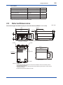
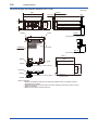
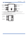
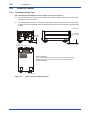
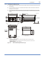
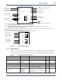
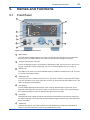

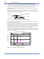
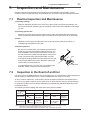
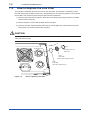
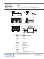
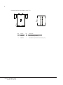


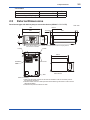

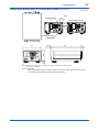
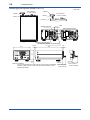
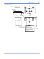
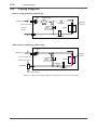
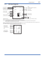

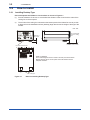
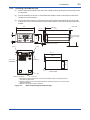
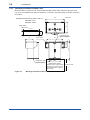
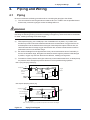
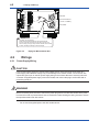
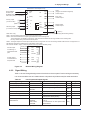
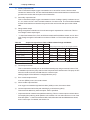
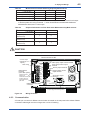

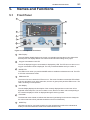
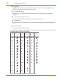
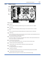

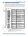
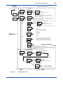
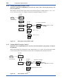
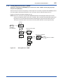
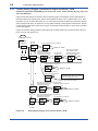
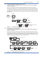
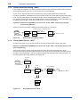
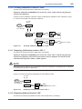
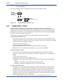
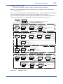
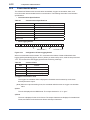
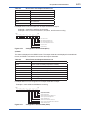
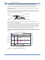
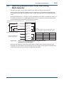
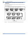
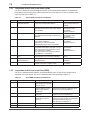
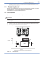
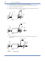
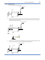
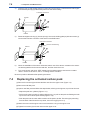
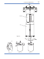

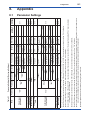

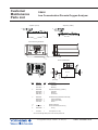
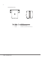


![OX400 低濃度ジルコニア式酸素濃度計 [スタイル:S2]](http://vs1.manualzilla.com/store/data/006674863_2-5ff04975cb5ce9e53bdc881e94cdb51c-150x150.png)