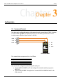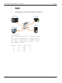
1
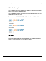
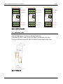
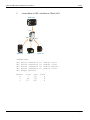
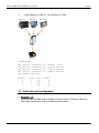
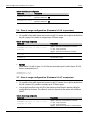
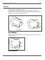
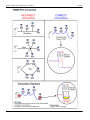
SGW1-IA2-MMP Modbus Multiplexer User’s Manual Exemys Exemys Products are in constant evolution to satisfy our customer’s needs. For that reason, the specifications and capabilities are subject to change without prior notice. Updated information can be found at www.exemys.com Copyright © Exemys, 2006 All Rights Reserved. Rev. 5 www.exemys.com Rev. 5 Pageii SGW1-IA2-MMP Modbus Multiplexer User’s Manual Exemys Table of Contents INTRODUCTION 5 1.1 Purpose of the manual _________________________________________________ 5 1.2 Conventions, terms and acronyms ________________________________________ 5 1.3 Product Description ___________________________________________________ 6 INSTALLATION 7 2.1 Power Connection ____________________________________________________ 7 2.2 Serial Ports Connection ________________________________________________ 7 2.3 Indicator Leds _______________________________________________________ 8 CONFIGURATION 9 3.1 Command Console____________________________________________________ 9 3.2 Serial Ports Configuration______________________________________________ 10 3.3 Pin de control RTS ___________________________________________________ 11 3.4 Master / Slave port configuration ________________________________________ 11 3.5 Serial slave port configuration __________________________________________ 14 3.6 Slave´s range configuration (Firmware V1.4.6 or previous)______________________ 15 3.7 Slave´s range configuration (Firmware V1.4.7 or superior) ______________________ 15 3.8 Master´s configuration ________________________________________________ 16 3.9 Other configuration parameters _________________________________________ 17 TECHNICAL SPECIFICATIONS 18 MOUNTING 19 Tables Table 1 - Acronyms_________________________________________________________________________5 Table 2 - Conventions_______________________________________________________________________5 Table 3 - Serial Ports Configuration ____________________________________________________________10 Table 4 - Serial slave port configuration ________________________________________________________15 Table 5 - Slave´s range configuration___________________________________________________________15 Table 6 - Master´s configuration ______________________________________________________________16 Table 7 - Other configuration parameters _______________________________________________________17 www.exemys.com Rev. 5 Pageiii SGW1-IA2-MMP Modbus Multiplexer User’s Manual Exemys Figures Figure 1 - Models __________________________________________________________________________6 Figure 2 - Power Connection__________________________________________________________________7 Figure 3 - Serial Ports Connection ______________________________________________________________8 Figure 4 - Indicator Leds _____________________________________________________________________8 Figure 5 – DIN rail Mounting ________________________________________________________________19 www.exemys.com Rev. 5 Pageiv SGW1-IA2-MMP Modbus Multiplexer User’s Manual Exemys Chapter 1 Chapter Introduction 1.1 Purpose of the manual The purpose of this manual is to provide instructions for a fast and simple installation and operation of SGW1-IA2-MMP. The manual starts with the product description and then provides instructions for proper installation of its hardware. Later on, it includes detailed information on SGW1-IA2-MMP configuration and operation. This manual is valid for firmware’s V1.4 or later. 1.2 Conventions, terms and acronyms The acronyms used in this manual are listed in the following chart: Table 1 - Acronyms Acronym Description Bps PC Bits per second Personal Computer GND Ground (Reference) Led Light Emision Diode The conventions listed below are used in this manual: Table 2 - Conventions www.exemys.com Convention Description A|B|C A set of possible values for command parameters. You can type A, B or C. n..m A range of possible values. You can type any value in the range including n and m. Rev. 5 Page5 SGW1-IA2-MMP Modbus Multiplexer User’s Manual Exemys 1.3 Product Description SGW1-IA2-MMP is a serial Modbus communications multiplexer. It allows you to connect up to 3 Modbus ASCII/RTU masters to one or more slaves. SGW1-IA2-MMP buffers the master’s polls giving them priorities, depending which of them came first, and then sends them to the slaves. There are several models of SGW1-IA2-MMP with different serial ports. Available models are: SGW1-310-00-IA2-MMP 3 RS232 ports 1 RS485 port SGW1-400-00-IA2-MMP 4 RS232 ports SGW1-130-00-IA2-MMP 1 RS232 port 3 RS485 ports Figure 1 - Models Each serial port can be configured with a different baud rate, parity and Modbus protocol (ASCII or RTU). So it is also possible to use SGW1-IA2-MMP as a converter. www.exemys.com Rev. 5 Page6 SGW1-IA2-MMP Modbus Multiplexer User’s Manual Exemys Chapter 2 Chapter Installation 2.1 Power Connection SGW1-IA2-MMP accepts an input voltage range of 10 to 30 Vdc. Power A Vdc B COM C D SGW1 Figure 2 - Power Connection 2.2 Serial Ports Connection SGW1-IA2-MMP supplies 4 serial ports, named COM A, COM B, COM C y COM D, to which you can connect Modbus devices. These can be etheir Slaves or Masters By default, the COM B is used to connect the slave and COMs A, C and D are used to connect the masters. www.exemys.com Rev. 5 Page7 SGW1-IA2-MMP Modbus Multiplexer User’s Manual SGW1-400-00-IA2-MMP 1 2 TD RD 5 6 TD RD 3 SGW1-310-00-IA2-MMP 4 RTS GND COM A RS232 DTE 8 7 RTS GND A Power B Vdc Exemys COM B RS232 DTE 1 2 3 TD RD 5 6 TD RD RTS GND 9 10 RD 13 14 12 16 4 GND 6 7 8 5 COM B RS232 DTE TR+ GND GND TR- A Power B Vdc B Vdc COM C RS232 DTE COM D RS232 DTE RD 9 10 D RTS GND 11 12 TR- TR+ GND GND 13 14 15 16 COM B RS485 C D TD COM A RS232 DTE COM C RTS GND 15 3 RTS COM RTS GND 11 2 RD Power D TD 1 TD A C RD COM A RS232 DTE 8 7 RTS GND COM TD SGW1-130-00-IA2-MMP 4 COM C RS232 DTE COM D RS485 TR- TR+ GND GND 9 10 11 12 TR- TR+ GND GND 13 14 15 16 COM C RS485 COM D RS485 Figure 3 - Serial Ports Connection 2.3 Indicator Leds SGW1-IA2-MMP features two indicator LEDs: green and yellow. If the yellow LED blinks it means the SGW1-IA2-MMP is sending data to the slaves. If the green LED blinks it means the SGW1-IA2-MMP is receiving data from the slaves. Figure 4 - Indicator Leds www.exemys.com Rev. 5 Page8 SGW1-IA2-MMP Modbus Multiplexer User’s Manual Exemys Chapter 3 Chapter Configuration 3.1 Command Console The device can be configured trough a serial command console over serial port COM A. You have to connect SGW1-IA2-MMP to a RS-232 port of a PC. To such effect, you must have a serial terminal program (Windows HyperTerminal or the like). 5 5 TxD 3 3 2 RxD 2 4 2 1 1 2 5 PC 3 6 A B 4 7 Power GND 1 TD 2 RD 4 GND 8 Vdc COM C D 9 10 11 12 13 14 15 16 SGW1-IA2-MMP The communications program must be set as follows: Baud rate: Parity: Data bits: Stop bits: Flow control: 9600 bps None 8 1 None (9600,N,8,1). You can enter the configuration mode through the serial port: Connect SGW1-IA2-MMP to a PC and configure the terminal emulation program to 9600,N,8,1. Turn on SGW1-IA2-MMP .During the first 7 seconds SGW1-IA2-MMP will wait for the CFG command. www.exemys.com Rev. 5 Page9 SGW1-IA2-MMP Modbus Multiplexer User’s Manual IMPORTANT Exemys Type CFG and press ENTER. The SGW1-IA2-MMP will display a welcome message to the configuration command console. After configuring the device use the command END. SGW1-IA2-MMP Modbus Multiplexer - Exemys (V1.4): -----------------------------------------------> 3.2 Serial Ports Configuration Serial port´s configuration parameters are: Baud Rate: Serial Port rate of transference by bits per second. Possible values are: 1200, 2400, 4800, 9600, 14400, 19200, 28800, 38400, 57600 and 115200 Parity: parity type. Possible Values are: NONE (without parity), EVEN (Even parity) and ODD (Odd parity). Protocol or Format: You may select Modbus/ASCII or Modbus/RTU. When you select Modbus/RTU the serial transmission pattern will be of 8 bits. If you select Modbus/ASCII, data bits will be 7. If you select Modbus/ASCII 8 bits, data bits will be 8. Packet Timeout (only for Modbus/RTU): Modbus/RTU packets are divided by time periods. This parameter allows changing the maximum time, to be calculated after the reception of the last byte of the packet, during which SGW1-IA2-MMP will presume that such packet has not yet finished arriving. After the lapse of the maximum time period, SGW1-IA2-MMP will presume the packet has finished its arrival. The packet timeout is calculated as units of time of a byte, being the minimum of 3 bytes. Use the following commands to configure SGW1-IA2-MMP´s serial ports. Note: values on bold are factory defaults. Table 3 - Serial Ports Configuration www.exemys.com Command Description BAUDx:(Baud_rate) Configures the COM X rate of transference by bits per second. Possible values are 1200, 2400, 4800, 9600, 14400, 19200, 28800, 38400, 57600 or 115200. PARITYx:(N|E|O) Configures COM X parity N = NONE E = EVEN O = ODD Rev. 5 Page10 SGW1-IA2-MMP Modbus Multiplexer User’s Manual Exemys PROTOCOLx:(R|A|8) Selects between Modbus/ASCII and Modbus/RTU in COM X R = Modbus/RTU A = Modbus/ASCII 8 = Modbus/ASCII 8 bits PKTTOUTx:(3..50) Modbus/RTU Packet Timeout in COM X (4) 3.3 Pin de control RTS The SGW1-IA2-MMP can andel the RTS pin to activate external devices, for example, a radio modem. The RTS pin can have a fixed value or it can be timed. When timed, the RTS pin will be activated for some time before sending data and will deactivate some time after sending data. This option applies to all RS232 ports. Table 1 - Pin de control RTS Comando Descripción RTSMODE: (0|1) Operating mode. 0 =Fixed 1 = Timed RTSDON: (0…1000) Delay befote sending data (50) RTSDOFF: (0…1000) Delay alter sending data (50) RTSLOGIC: (0|1) RTS polarity. 0 = Inverted 1 = normal 3.4 Master / Slave port configuration Master/Slave COM: This command specifies wether you will conect a Master or a Slave device to each port. Command Description Configures if a Master or a Slave will be connected to the COM MSCOM:(m|s)(m|s)(m|s)(m|s) m = a Master will be connected to this COM s = a Slave will be connected to this COM When this command is applied, the slave’s range configuration will reset. Ranges vary depending on the number of COMs configured as Slaves. www.exemys.com Rev. 5 Page11 SGW1-IA2-MMP Modbus Multiplexer User’s Manual Exemys Examples: 1. Connect Masters to COMs A & B, and Slaves to COMs C & D Modbus Master Modbus Slave COM C COM A Modbus Slave A B C Modbus Master D COM B >MSCOM:mmss OK, Device connected OK, Device connected OK, Device connected OK, Device connected OK, Ranges Deleted Master A A B B www.exemys.com First 1 101 1 101 Last 100 247 100 247 COM D is: is: is: is: (COM (COM (COM (COM A) B) C) D) Master Master Slave Slave Slave C D C D Rev. 5 Page12 SGW1-IA2-MMP Modbus Multiplexer User’s Manual 2. Exemys Connect Master to COM C, and Slaves to COMs A, B & D Modbus Master COM C A B C COM A D COM D COM B Modbus Slave Modbus Slave Modbus Slave >MSCOM:ssms OK, Device connected OK, Device connected OK, Device connected OK, Device connected OK, Ranges Deleted Master C C C www.exemys.com First 1 86 171 Last 85 170 247 is: is: is: is: (COM (COM (COM (COM A) B) C) D) Slave Slave Master Slave Slave A B D Rev. 5 Page13 SGW1-IA2-MMP Modbus Multiplexer User’s Manual 3. Exemys Connect Masters to COMs B, C y D, and Slave/s to COM A Modbus Master Modbus Master COM C COM B Modbus Master COM D A B C D COM A Modbus Slave >MSCOM:smmm OK, Device connected OK, Device connected OK, Device connected OK, Device connected OK, Ranges Deleted Master B C D First 1 1 1 Last 247 247 247 is: is: is: is: (COM (COM (COM (COM A) B) C) D) Slave Master Master Master Slave A A A 3.5 Serial slave port configuration www.exemys.com Slave´s time out: Each time SGW1-IA2-MMP sends a message to a slave it waits for an answer. If the slave takes longer than this time it will go ahead with the next master. Rev. 5 Page14 SGW1-IA2-MMP Modbus Multiplexer User’s Manual Exemys Table 4 - Serial slave port configuration Command Description SLVTOUT:(50..1000) Changes slave´s answer time out (all COMs). Expressed in milliseconds. (50) SLVTOUTx:(50..1000) Changes slave´s answer time out. (COMx) Expressed in milliseconds. (50) 3.6 Slave´s range configuration (Firmware V1.4.6 or previous) It’s possible to limit which slaves each master can poll. If a master tries to poll an invalid slave the poll is ignored. It´s posible to configure up to 32 slaves ranges. Table 5 - Slave´s range configuration Command Description SRANGEADD:(A|B|C|D),(1..247),(1..247), (A|B|C|D) Adds a slave´s range to the master. (A|B|C|D ): the port to which the Master is connected (1... 247) : range’s lower limit (1... 247) : range’s upper limit (A|B|C|D) : the port to which the Slave is connected SRANGEDEL:(A|B|C|D),(1..247),(1..247), (A|B|C|D) Deletes a slave´s range to the master. SRANGELIST Lists a the slave´s ranges. Example Allow master A to talk to slaves 1 to 20, that are connected to port B, and to slaves 35 to 39, that are connected in port C. SRANGEADD:A,1,20,B SRANGEADD:A,35,39,C 3.7 Slave´s range configuration (Firmware V1.4.7 or superior) It’s possible to limit which slaves each master can poll. If a master tries to poll an invalid slave the poll is ignored. It’s possible to configure up to 32 slaves ranges. You can apply an offset to the Unit ID on the queries received from the masters and before sending them to the slaves. This allows to access the slaves from the master with a different Unit ID Table 6 - Slave´s range configuration www.exemys.com Command Description SRANGEADD:(A|B|C|D),(1..247),(1..247), [A|B|C|D],[0..254] Adds a slave´s range to the master. (A|B|C|D ): the port to which the Master is connected (1... 247) : range’s lower limit (1... 247) : range’s upper limit [A|B|C|D] : the port to which the Slave is connected (optional Rev. 5 Page15 SGW1-IA2-MMP Modbus Multiplexer User’s Manual Exemys field) [0... 254] : offset to apply to the Unit ID before sending it to the slave (optional field) SRANGEDEL:(A|B|C|D),(1..247),(1..247), [A|B|C|D],[0..254] Deletes a slave´s range to the master. SRANGELIST Lists a the slave´s ranges. Example 1 Allow master A to talk to slaves 1 to 20, that are connected to port B, and to slaves 35 to 39, that are connected in port C. SRANGEADD:A,1,20,B SRANGEADD:A,35,39,C Example 2 The user wants to access four slaves from two masters. But it happens that two slaves have Unit ID 1 and the other two have have Unit ID 2. The devices will be connected like this to the SGW1: COM A: Master #1 COM B: Master #2 COM C: First pair of slaves with Unit ID 1 and 2 COM D: Second pair of slaves with Unit ID 1 and 2 The commands to configure the SGW1 are SRANGEADD:A,1,2,C,0 SRANGEADD:A,3,4,D,2 SRANGEADD:B,1,2,C,0 SRANGEADD:B,3,4,D,2 Both masters will be able to access the four slaves using Unit IDs 1 and 2 for the first pair and Unit IDs 3 and 4 for the second pair. 3.8 Master´s configuration Priority: Each master can have a different priority level. 0 is the highest priority. The device is going to wait 10 extras milliseconds to answer to the master per priority step. Table 7 - Master´s configuration www.exemys.com Command Description PRIORITYx:(0..100) Master X ´s priority level. (0) Rev. 5 Page16 SGW1-IA2-MMP Modbus Multiplexer User’s Manual Exemys 3.9 Other configuration parameters Table 8 - Other configuration parameters www.exemys.com Comando Descripción HELP Lists all available commands with their syntax and a descriptive text. LIST Shows SGW1-IA2-MMP configuration FACTRESET Resets to default configuration END Ends configuratio mode and switches to RUN mode. Rev. 5 Page17 SGW1-IA2-MMP Modbus Multiplexer User’s Manual Exemys Technical Specifications www.exemys.com • Serial Protocols: Modbus RTU / ASCII / ASCII 8 bits. • Serial Interface: 4 serial ports on 4 terminal block connectors . • Devices Supported: Any Modbus RS232/RS485 serial port device. • Baud Rates: 1200, 2400, 4800. 9600, 14400, 19200, 28800, 38400, 57600, 115200 • Modbus Masters: Up to 3. • Modbus Slaves: Up to 3. • Management: RS232 serial console. • Indicators: Data to slave. Data from slave. • Dimension / Weight: 4.49 x 3.94 x 0.89 in. (HxWxL). (114 x 100 x 22.5 mm). 0.31 Lbs (0.140 Kg). • Power Supply: 10 a 30 Volts DC. 200mA max. • Enviromental: Operating temperature: 23 to 149 ºF (-5 to 65 ºC). Storage temperature: -40 to 167 ºF (-40 to 75 ºC). • Optional Accessories: Programming cable. • Warranty / Support: 1-year limited warranty. Technical Support included. Rev. 5 Page18 SGW1-IA2-MMP Modbus Multiplexer User’s Manual Exemys Mounting El SGW1-A2-MMP can be mounted on a DIN rail. To mount the device to the DIN rail (as shown in figure 5), tip the upper part of the device towards the rail and place the slot on the edge of the rail (A). Press firmly the device towards the rail until it is fixed. You’ll hear it click when it is does (B). (A) Rail DIN Rail DIN Click ! (B) Figure 5 – DIN rail Mounting To detach the device off the DIN rail (figure 6), pull downwards the device’s metallic clip (C) and then remove from rail. Rail DIN (C)kd Figure 6 – Detaching the device www.exemys.com Rev. 5 Page19 SGW1-IA2-MMP Modbus Multiplexer User’s Manual www.exemys.com Exemys Rev. 5 Page20