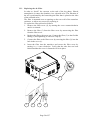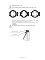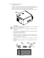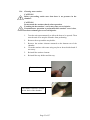
1
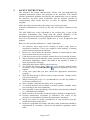
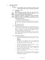
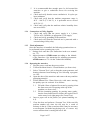
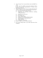
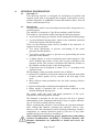
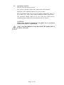
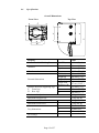
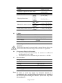
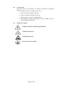
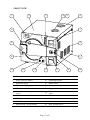
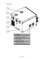
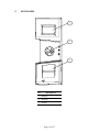
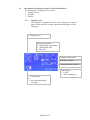
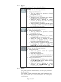
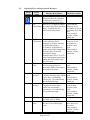
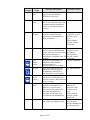
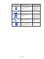
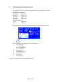
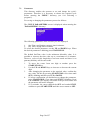
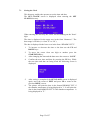
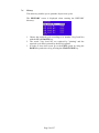
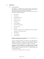
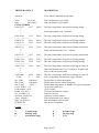
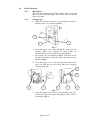
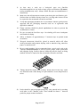
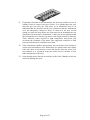
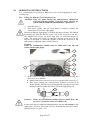
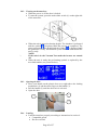
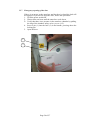
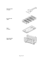
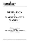
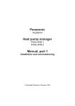
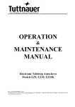
OPERATION & MAINTENANCE MANUAL Pre/Post-vacuum Class B Table–top Autoclave Model ELARA 11 Cat. No. MAN205-0342001EN Rev Q Manufactured by: Tuttnauer Co. Ltd., Har Tuv Industrial zone B P.O.Box 170, Beit Shemesh 99000, IsraelTel: 972 2 9904611, Fax: 972 2 9904730 Tuttnauer U.S.A. Co, Ltd. 25 Power Drive Hauppauge, NY, 11788, USA. Tel (631) 737 4850, (800) 624 5836, Fax: (631) 737 0720 TABLE OF CONTENT 1. GENERAL ................................................................................................................ 4 1.1. 1.2. 1.3. INCOMING INSPECTION ........................................................................... 4 WARRANTY .............................................................................................. 4 WARRANTY STATEMENT ......................................................................... 5 2. SAFETY INSTRUCTIONS .................................................................................... 6 3. INSTALLATION ..................................................................................................... 7 3.1. PLACING ................................................................................................... 7 4. GENERAL INFORMATION ............................................................................... 10 4.1. 4.2. 4.3. 4.4. 4.5. 4.6. 4.7. 4.8. 4.9. 4.10. 4.11. INTENDED USE ....................................................................................... 10 INTRODUCTION ...................................................................................... 10 OPERATING CONDITIONS ...................................................................... 11 SPECIFICATIONS .................................................................................... 12 UTILITIES ............................................................................................... 13 ENVIRONMENT EMISSION INFORMATION ............................................. 13 ELECTRICAL DATA ................................................................................ 13 CONSTRUCTION ..................................................................................... 14 SYMBOL DESCRIPTION .......................................................................... 14 WATER QUALITY ................................................................................... 15 DIRECTIVES AND STANDARDS ............................................................... 16 5. KEYBOARD .......................................................................................................... 19 5.1. 5.2. DESCRIPTION AND FUNCTIONS OF THE FRONT PANEL KEYBOARD ..... 20 DISPLAYED ERROR AND OPERATIONAL MESSAGES ............................. 22 6. STERILIZATION PROGRAMS ......................................................................... 25 6.1. 6.2. 6.3. 6.4. 6.5. 6.6. 6.7. PROGRAM 1: FLASH 134 ........................................................................ 26 PROGRAM 2: WDRY 134 ....................................................................... 27 PROGRAM 3: NODRY 121 ...................................................................... 28 PROGRAM 4: WDRY 121 ....................................................................... 29 PROGRAM 5: DELICATE 121 .................................................................. 30 TEST 1: B&D TEST ................................................................................ 31 TEST 2: VACTEST .................................................................................. 32 7. MODIFYING PARAMETERS AND OTHER DATA ....................................... 33 7.1. 7.2. 7.3. 7.4. MENU ..................................................................................................... 33 PARAMETERS ......................................................................................... 34 SETTING THE CLOCK ............................................................................. 35 HISTORY................................................................................................. 36 8. PRINTER................................................................................................................ 37 8.1. 8.2. PRINTER OPERATION ............................................................................ 37 PRINTER HANDLING .............................................................................. 39 9. PREPARATION BEFORE STERILIZATION .................................................. 41 Page 1 of 57 10. OPERATING INSTRUCTIONS .......................................................................... 44 10.1. 10.2. 10.3. 10.4. 10.5. 10.6. 10.7. 10.8. 10.9. 10.10. FILLING THE MINERAL-FREE WATER RESERVOIR.............................. 44 TURNING ON THE AUTOCLAVE .............................................................. 45 OPENING THE DOOR ............................................................................... 45 LOADING ................................................................................................ 45 CLOSING THE DOOR .............................................................................. 46 SELECTING A PROGRAM ........................................................................ 46 UNLOADING............................................................................................ 46 STOPPING THE PROCESS ........................................................................ 46 CANCELING THE ERROR MESSAGE ..................................................... 46 SLEEP MODE .......................................................................................... 46 11. MAINTENANCE INSTRUCTIONS ................................................................... 47 11.1. 11.2. 11.3. 11.4. 11.5. 11.6. 11.7. PREVENTIVE AND SCHEDULED MAINTENANCE .................................... 47 DRAINING THE RESERVOIRS ................................................................. 49 REPLACING THE AIR FILTER ................................................................ 50 REPLACING THE DOOR GASKET ........................................................... 51 CHECKING THE SAFETY VALVE ............................................................ 52 CLEANING WATER STRAINER ................................................................ 53 EMERGENCY OPENING OF THE DOOR .................................................... 54 12. TROUBLESHOOTING ........................................................................................ 55 13. SPARE PARTS LIST ............................................................................................ 57 14. ACCESSORIES ..................................................................................................... 57 Page 2 of 57 TABLE OF ILLUSTRATIONS FRONT VIEW ................................................................................................................ 17 REAR VIEW .................................................................................................................. 18 TRAY HANDLE ............................................................................................................. 56 POUCH RACK ............................................................................................................... 56 TRAY ............................................................................................................................ 56 TRAY HOLDER ............................................................................................................. 56 Page 3 of 57 1. GENERAL Read the Operating Instructions carefully, before beginning any operation on the autoclave! 1.1. Incoming Inspection Upon receiving your Tuttnauer Autoclave, carefully inspect the outside of the shipping carton for signs of damage. If any damage to the carton is found, note the location with respect to the autoclave and check that area of the autoclave carefully once it is fully unpacked. Observe packing method and retain packing materials until the unit has been inspected. Mechanical inspection involves checking for signs of physical damage such as: scratched panel surfaces, broken knobs, etc. If any damage is found, contact your dealer as soon as possible so that they can file a claim with the shipping carrier and also notify Tuttnauer. All Tuttnauer products are carefully inspected prior to shipment, and all reasonable precautions are taken in preparing them for shipment, to assure safe arrival at their destination. Note: Lifting and carrying should always be done by two people. 1.2. Warranty We certify that this instrument is guaranteed to be free from defects in material and workmanship for one year against faulty components and assembly. This warranty does not include routine cleaning and preventive maintenance which needs to be performed according to instructions in section 11 (Preventive and Scheduled Maintenance). Tuttnauer warrantees all new autoclaves for a period of one full year, covering both parts and labor. This one year warranty covers defects in materials and workmanship on every part in the autoclave except the HEPA filter and the door gasket. This warranty does not apply to any instrument that has been subjected to misuse, neglect, accident or improper installation or application, nor shall it extend to autoclaves that have been repaired or altered outside the factory without prior authorization from Tuttnauer. Tuttnauer’s obligation is limited to the repair or replacement of parts for the autoclave. This warranty will be void if the unit is not purchased from an authorized Tuttnauer dealer. No other warranties or obligations are expressed or implied. Warning Sterilization programs 1-5 are not considered by the Food and Drug Administration to be standard sterilization cycles. In the United States, use only sterilizer accessories that have been cleared by the Food and Drug Administration for the selected sterilization cycle parameters (time and temperature). Users should only use sterilizer accessories (such as sterilization wraps, sterilization pouches, chemical indicators, biological indicators, and sterilization cassettes) that have been cleared for use in their markets. The Autoclave should not be used in a manner not described in this manual! Page 4 of 57 1.3. Warranty Statement To activate the warranty, the registration card must be completed and returned to Tuttnauer within fourteen (14) days of purchase or you may call our customer service department at the number listed below. No product will be received or accepted for repair without prior return authorization from Tuttnauer. All transportation charges to and from Tuttnauer must be paid by the owner of the autoclave. During the first 90 days after purchase of an autoclave, Tuttnauer will pay shipping costs on an individually evaluated basis and ONLY with pre-approval. Note: If you have any questions or there are any difficulties with this instrument and the solution is not covered in this manual, please contact your dealer or Tuttnauer USA Co. Do not attempt to service this instrument yourself. Tuttnauer USA Co., Ltd., 25 Power Drive Hauppauge, NY 11788, USA : (800) 624 5836, (631) 737 4850, Fax: (631) 737 0720 e-mail:[email protected]. Page 5 of 57 2. SAFETY INSTRUCTIONS The autoclave has unique characteristics. Please read and understand the operation instructions before first operation of the autoclave. This manual includes instructions guidance provided by the manufacturer: how to operate the autoclave, the door safety mechanism, and the hazards involved in circumventing safety means and how to select an adequate sterilization program. Make sure that you know where the main power switch is located. Autoclave maintenance is crucial for the safe and effective function of the device. The daily B&D test, at the beginning of the working day, is part of the preventive maintenance plan, along with the annual validation of the sterilization processes that ensures appropriate sterilization conditions. Never use the autoclave to sterilize liquids since it is not designed for that purpose. Below are the operating instructions – safety instructions: 1. 2. 3. 4. 5. 6. 7. 8. 9. 10. 11. 12. 13. 14. 15. 16. All autoclave users must receive training in proper usage from an experienced employee. Every new employee must undergo a training period under an experienced employee. Before use, check inside the autoclave chamber to ensure that no items have been left from the previous cycle. Load trays in such a way as to allow steam to move freely among all items. When sterilizing plastic materials, make sure that the item can withstand sterilization temperature. Plastic that melts in the chamber is liable to cause a great deal of damage. Individual glass bottles shall be placed on a tray. On closing the device door, make sure it is properly locked before activating. Verify that DOOR OPEN symbol is replaced by the load number. Verify once again that you have chosen the appropriate sterilization program. Open the door slowly to allow steam to escape and wait 1 minute before you remove the load. When removing the trays it is recommended to use the tray handle or wear heat resistant gloves. Once a month, ensure that the safety valve is operating. A certified inspector must perform a periodic pressure chamber safety test according to the local regulations. Once annually, or more frequently, effectiveness tests must be performed, i.e., calibration and validation. Make sure there are no leaks, breaks, blockages, whistles or strange noises. Perform maintenance operations as instructed. The owner of the autoclave is responsible to perform the maintenance operations. Notify the person in charge immediately of any deviation from the normal functioning of the device. Protective equipment and clothes and other safety instructions should be implemented in accordance with local and national regulations and/or rules! Page 6 of 57 3. INSTALLATION 3.1. Placing CAUTION: The installation and all operations described in this chapter must be done only by an authorized technician. 3.1.1 Lifting and carrying CAUTION: Before moving the autoclave, Make sure that the electric cord is disconnected from the power, and there is no pressure in the chamber and in the generator. Attention! The pressure of the generator does not decrease immediately when the equipment is turned off. Wait approx. ½ an hour to verify that the pressure has decreased to atmospheric pressure. 1. Disconnect the power supply cord. 2. Drain the water from both reservoirs. To avoid injuries, lifting and carrying should be done with at least two persons or by using a fork-lift or any other mechanical aid. Do not drop the device! 3.1.2 Unpacking the autoclave Unpack the autoclave and inspect for mechanical damage upon receipt. Observe packing method and retain packing materials until the unit has been inspected. Mechanical inspection involves checking for signs of physical damage such as: scratched panel surfaces, broken knobs, etc. To avoid injuries, lifting and carrying of the autoclave should be done with at least two persons or by using a fork-lift or any other mechanical aid. 3.1.3 Installation preparations 1. Check and verify that the counter carrying the autoclave is a rigid and leveled surface and can carry a load of 225 lbs (102kg). Attention: The Elara11 is not designed for use on any standard slide out shelf. If it is necessary to use a slide out shelf, it must be tested and/or rated for 225 lbs or more 2. Check and verify that the counter dimensions are, at least, 22” wide x 24” deep (55cm x 63.5cm). 3. Keep the back and the sides of the autoclave approximately 2” (5 cm) away from the wall to allow ventilation and facilitate the device disconnection. 4. If placed in a cabinet, verify that the rear of the cabinet is open to allow ventilation. Insufficient space for ventilation may result in an increase of the autoclave's temperature that may cause a malfunction or damage the instrument. Page 7 of 57 5. It is recommended that enough space be left around the autoclave to give a technician access for servicing the machine. 6. Check and verify that the room ventilation is 10 cycles per hour minimum. 7. Check and verify that the ambient temperature range is 41°F - 104°F (5ºC-40ºC), it is preferable not to exceed 86°F (30ºC). 8. Check and verify that the ambient relative humidity does not exceed 85% 3.1.4 Connections to Utility Supplies 1. Check and verify that the power supply is a 1 phase, 230Vac ±5%, 50/60Hz (as appropriate), 15A supply. 2. Check and verify grounding of the autoclave. 3. Check and verify that the electrical net is protected with a current leakage safety relay. 3.1.5 Final adjustments Once the autoclave is installed, the following operations have to be performed before operating any cycle: 1. Setting clock and date (See instruction in the user manual sec. 7.3). 2. Adjust parameter ATMPressure according to the altitude of the autoclave (See instruction for adjusting parameters ATMPressure sec.7.2.6 in the Technicians Manual) 3.1.6 Operating the autoclave 1 Plug the power cord into the power socket. 2 Turn on the Main Switch / Circuit Breaker (see front view). 3 Select "Vacuum Test" cycle to keep the steam generator and heating elements from heating up. See Selecting a program sec 10.6. 4 Open the door of the autoclave and remove the trays and the packaging material. 5 Fill the Mineral Free Water Reservoir with water meeting the quality specs in section 4.10 as follows: 5.1 Fill with 4 liters of mineral free water by pouring it into the front reservoir fill opening at the top of the machine (see front view).”. 5.2 Fill the remaining quantity by pouring water gently, into the front funnel until it reaches the required level on the water level sight gauge (See Front View). 6 Insert a paper roll in the printer (see printer handling sec. 8.2). 7 Close the door and perform a Vacuum Test. If the test fails perform another test since the fail may be a result of moisture in the air. If the second test fails it may be necessary to run Program 2 with the long drying cycle to remove any excess moisture that is causing the test to fail. Page 8 of 57 8 If the Vacuum Test is successful then select the B&D Test cycle. At this stage the chamber and steam generator will be heating up. It will take approximately 15 minutes (from selecting the B&D Test). 9 While waiting for the unit to heat up explain and instruct the operator as follows (use the operation manual as reference): 9.1 Operation principals of the autoclave. 9.2 Preparation for sterilizing instruction including loading instructions. 9.3 Intended use of each cycle. 9.4 Selecting a cycle. 9.5 Water filling method. 9.6 Displayed error and operational messages. 9.7 Monitoring and changing parameters. 9.8 Printer handling. 9.9 Maintenance instructions 10 Perform a B&D test with a chemical indicator. 11 The operator shall perform a cycle under supervision of the technician. Page 9 of 57 4. GENERAL INFORMATION 4.1. Intended Use This table-top autoclave is designed for sterilization of medical and surgical goods such as unwrapped and wrapped, solid, hollow, porous products and tubes in ophthalmic, dental and medical clinics, first aid rooms, small laboratories etc. 4.2. Introduction This autoclave model is an electrically heated sterilizer using steam as a sterilizing agent. The autoclave is designed as Type B in accordance with EN13060. This model is a prevacuum sterilizer having the following features; An air removal stage (prevacuum), before starting the sterilizing stage. A post-sterilization drying phase, based on the combined operation of heat and vacuum with air inlet pulses. There are the following safety devices installed in the autoclave to optimize its safe operation: Two safety thermostats, to prevent over-heating of the steam generator and the chamber. Two safety pressure valves to prevent over pressurizing the steam generator or the chamber. A digital display is used for monitoring and control purposes. This device displays the pressure in kPa, psia or psig, according to the operators needs. The pressure is displayed for both the pressure in the chamber and the pressure in the steam generator. Temperature can be displayed in either °F or °C according to the operators needs The advantages of the prevacuum sterilizer are as follows: Removal of residual air from packs and porous load and most kinds of tubes (rubber, plastic etc.) by vacuum at the first stage of the cycle. More efficient steam penetration into the load; assuring effective sterilization. Improved temperature uniformity throughout the chamber. Better drying of materials due to the vacuum achieved in the chamber during the drying cycle. The printer prints the preset and actual parameters of the cycle (temperature, time and pressure/vacuum). This Manual is intended for the user and gives the user a general understanding of the instrument and the best ways to operate and take care of it in order to obtain effective results. Before operating this autoclave read carefully the Operation Manual. After reading this Manual, operating the autoclave will be easy. However since this instrument is built with high technology sensitive components, no attempt should be made by the user or any other unauthorized person to repair or recalibrate it. Only technical personnel having proper qualifications and holding technical documentation (including a Technician Manual) and adequate information are authorized to install and service the apparatus. Page 10 of 57 4.3. Operating Conditions This device is for indoor use only! The sterilizer should be loaded only with autoclavable material! Minimum room ventilation shall be10 cycles per hour The environment shall not exceed an ambient temperature range of 41ºF-104ºF (5ºC-40ºC) and a relative humidity of 85% respectively. The operation altitude shall not be over 6500 feet (2000 meters) (ambient pressure shall not be lower than 80 kPa (11.6 psia)). CAUTION! Waste water should be brought into the public net in accordance with the local rules or requirements ONLY NON-HAZARDOUS LIQUIDS SHALL BE DISPOSED IN PUBLIC SEWAGE! Page 11 of 57 4.4. Specifications Overall Dimensions Front View Top View Property Value Max. Allowable Working Pressure Chamber (MAWP) Diameter Depth Chamber volume External dimensions Distance between supporting legs F - Front legs F1 - Rear legs Width (A) Height (B) Length (C) Length with open door (D) K F F1 Maximum load per item Maximum load per tray Maximum solid load Maximum textile load W H L Tray dimensions No. of trays Page 12 of 57 2.8 bar (40 psi) 280 mm (11”) 504 mm (19.8”) 28.5 lit. (7.5 gal) 530 mm (20.8”) 444 mm (17.4”) 645 mm (25.4”) 997 cm (39.25”) 452 mm (17.8”) 315 mm (12.4”) 400 mm (15.7”) 0.5 kg (1.1 lb) 2.0 kg (4.4 lb) 8.0 kg (17.6 lb) 2.0 kg (4.4 lb) 170 mm (6.7”) 21 mm (0.8”) 415 mm (16.3”) 5 Property Value Weight 148 lb (67.1 kg) 1.71 N/m2 (0.036 lb/ft2) 184 lb (83.4 kg) 63 cm (24.8”) 71 cm (28.0”) 80 cm (35.8”) 0.36 m3 (14.5 ft3) Weight per support area (max. load) Shipping weight Width Height Shipping dimensions Length Volume Max. water volume Mineral-free water reservoir Min. water volume Max. water Used (waste) water reservoir volume 4.5. 6.6 lit. (1.74 US gal) 2.6 lit. (0.68 US gal) 5.2 lit. (1.37 US gal) Utilities Utility Value Mineral free water See table in para 4.10. * 1 phase, /230 ±5% Vac, 50/60Hz 15A Power supply Recommended circuit breaker * According to the local network. Attention: The electrical net must be protected with a current leakage safety relay. The electrical network must comply with local rules or regulations. 4.6. Environment Emission Information 1. The peak sound level generated by the autoclave is 65dBa with background noise of 48 dBa. 2. 4.7. Note: The total heat per hour transmitted by the autoclave is <200Wh. Electrical Data Property Value Total Power 2300W Voltage 1 ph / 230 Vac Amperage 10A Protection against electrical shock Class I (IEC 60601-1) Mains supply fluctuation +/- 5% In order to avoid any injury by electrical hazard, it is recommended that a ground fault protection device be installed in the electrical panel feeding the autoclave (local codes may make this mandatory). Page 13 of 57 4.8. Construction The main parts of the autoclave are made of materials as indicated below: Chamber is built of stainless steel 316 L. Door is made of stainless steel 316. Trays are made of stainless steel 304. Water reservoir is made of polyethylene. Door handle is made of hard plastic material, which is safe to touch and thermo-insulated. 4.9. Symbol Description Caution! Consult accompanying documents Caution! Hot surface. Caution! Hot steam. Protective earth (Ground) Page 14 of 57 4.10. Water Quality Physical characteristics and contaminants levels The distilled or mineral – free water supplied to the autoclave should have the physical characteristics and maximum acceptable level of contaminants indicated in the table below: Physical Characteristics and Maximum acceptable contaminants levels in water for sterlizers (According to ANSI/AAMI ST79:2006). Element Condensate – allowable content Evaporate residue Silica Iron Cadmium Lead Rest of heavy metals ≤15 miligrams/liter (mg/l) ≤2 mg/l ≤0.2 mg/l ≤0.005 mg/l ≤ 0.05 mg/l ≤0.1 mg/l Chloride Phosphate Conductivity pH value Appearance Hardness ≤3 mg/l ≤0.5 mg/l ≤50 μs/cm 6.5 to 8 Colorless, clean, without sediment ≤0.1 mmol/l Compliance with the above data should be tested in accordance with acknowledged analytical methods, by an authorized laboratory. Attention: We recommend testing the water quality once a month. The use of water for autoclaves that does not comply with the table above may have severe impact on the working life of the sterilizer and can invalidate the manufacturer’s guarantee. Page 15 of 57 4.11. Directives and Standards Every autoclave meets the provisions of the following Directives and is in compliance with the following Standards: 4.11.1. Technical Standards 1. ANSI/AAMI ST55 – Small Steam Sterilizers. 2. ASME Code, section VIII division 1 for pressure vessels. 3. UL 61010-1 electrical equipment for laboratory use; general requirements 4. IEC 61010-2-040 particular requirements for sterilizers and washer disinfectors used to treat medical materials. The following standards were taken in consideration: 4.11.2. 5. ANSI/AAMI ST79, Comprehensive guide to steam sterilization and sterility assurance in health care facilities 6. ISO 17665-1:2006 specifies requirements for the development, validation and routine control of a moist heat sterilization process for medical devices. Quality standards The manufacturing plant meets the following quality standards: 1. EN ISO 9001:2008– Quality System 2. ISO 13485:2003 – Quality systems – Medical devices. 3. 21 CFR 820 – Quality System Page 16 of 57 FRONT VIEW 1 2 3 4 5 6 18 7 17 8 16 9 13 15 14 13 12 11 No. Description No. Description 1 Water reservoir funnel 10 Operating keypad 2 Autoclave cover 11 Printer cover 3 Water level sight gauge 12 Printer (standard) 4 13 6 Mineral-free water reservoir cover Chamber and steam generator safety valves Waste water reservoir cover 15 Legs Mineral-free water reservoir drain valve Waste water reservoir drain valve 7 Display 16 Door cover 8 Ventilation grill 17 Door switch 9 Main switch / circuit breaker 18 Door closing device 5 14 Page 17 of 57 10 REAR VIEW 1 2 3 4 5 6 3 No. Description 1 Mineral-free water reservoir cover 2 Waste water reservoir cover 3 Ventilation grills 4 Air filter service cover 5 Opening for calibration 6 Main power electric cable socket Page 18 of 57 5. KEYBOARD 1 2 3 No. Description 1 Display 2 Keypad 3 Printer Page 19 of 57 5.1. Description and Functions of the Front Panel Keyboard The front panel is composed of 3 sections: 1. Display screen. 2. Keypad. 3. Printer 5.1.1. Display screen The display is a graphical screen used to display the current status of the autoclave and any Operational Messages or Error Messages. Program icon Program parameters Sterilization temperature Sterilization time Dry time Chamber temperature Chamber pressure Steam generator pressure Load number or Error and operational messages Page 20 of 57 Time display: ― Clock ― Time countdown 5.1.2. Keypad The keypad consists of 3 keys as described below: UP key This key has the following functions: In the menu directories: o This key enables the operator to browse through the cycles. In the directories available: o When the cursor is blinking on a number, the UP ▲ key increases its value. o When the cursor is blinking on a menu selection, the UP ▲ key allows browsing backward through the menu. o When adjusting a parameter and the cursor is blinking on “SET” or “EXIT” the UP ▲ key activates that procedure.” DOWN key This key has the following functions: In the menu directories: o This key enables the operator to browse through the cycles. In the directories available: o When the cursor is blinking on a number, the DOWN ▼ key decreases its value. o When the cursor is blinking on menu selection, the DOWN ▼ key allows browsing forward through the menu. o When adjusting a parameter and the cursor is blinking on “SET” or “EXIT” the DOWN ▼ key activates that procedure. START/STOP key This key has the following functions: In the main screen: o Starts the process when the required program was chosen. o Stops the current process. o Cancels the ERROR message displayed on the screen and opens the electric door lock. In the menu directories: o When the cursor is blinking on a number, the START/STOP key enables moving to the next position. o When the cursor is blinking on a menu selection, the START/STOP key activates that selection. 5.1.3. Printer The printer prints the detailed history of each cycle performed by the autoclave. The printing is made on thermal paper with 24 characters per line and contains the record information for subsequent consideration. Page 21 of 57 5.2. Displayed Error and Operational Messages Error Error Number Name Err:001 Pt1 out Err:002 Err:003 Err:005 Err:007 Err:008 Err:009 Err:011 Message Description This error # and symbol are displayed when the Chamber Temperature sensor Pt1 is disconnected or out of range. Low This error # is displayed when Temperature the temperature drops for more than 1 second below the sterilization temperature. Corrective Action Call the technician. Check that the autoclave is not overloaded or check for leakage from the door. If the problem persists, call the technician. High This error # is displayed in one Check that the Temperature of the following cases: autoclave is not During Pre-vacuum, Heating overloaded or or Sterilization Stages: perform a new If Chamber Temperature is cycle. greater than Limit Temperature If the problem for more than 10 seconds. persists, call the Sterilization Stage: technician. If temperature rises 3°C (6°F) above sterilization temperature during the sterilization stage for 10 seconds. High Gen This error # is displayed when Perform a new Press the Generator pressure is cycle. more than 40kPa (6psi) above If the problem the required pressure. persists, call the technician. High This error # is displayed if Perform a new Pressure Chamber Pressure raises 20kPa cycle. (3psi) above sterilization If the problem pressure for 5 seconds during persists, call the the sterilization stage. technician. Low This error # is displayed if Check for leakage Pressure Chamber Pressure drops from the door. bellow the sterilization Perform a new pressure for 5 seconds during cycle. the sterilization stage. If the problem persists, call the technician. Time Error This error # is displayed if the Call the technician. real time clock is faulty. Door is This error # is displayed when Open and close the Open the door is open during the door, then run a cycle. new cycle. If the problem persists, Call the technician. Page 22 of 57 Error Error Number Name Err:012 Manual Stop Message Description Corrective Action This error # is displayed and cycle is aborted after the STOP key is pressed. Err:013 Air Valve Error This error # is displayed after Replace air filter. the air valve has been open for 3 minutes and the chamber is unable to reach atmospheric pressure. Err:014 Low Vacuum The error # is displayed if the chamber cannot reach the required vacuum conditions after 20 minutes. Verify that the door is properly closed. Perform a new cycle. If the problem persists, call the technician. Err:015 Low Heat Err:016 Press Sensor Cutout Check that the autoclave is not overloaded. If the problem persists, call the technician. Call the technician. Err:017 Pt2 out Err:018 Press Sensor Cutout Err:020 No Gen water This error # is displayed during the Pre-Vacuum and Heating stages if the system can't reach the required pressure or temperature conditions after 20 minutes. This error # and symbol are displayed if the chamber pressure sensor is disconnected or out of range. This error # and symbol are displayed when the Jacket Temperature sensor Pt2 is disconnected or out of range. This error # and symbol are displayed if steam generator pressure sensor is disconnected or out of range. This error # is displayed if the generator electrode has no water for a specific time. This error # may appear the first time the autoclave is used and, in this case, does not indicate any malfunction. Err:021 Test Fail This error # is displayed if one of the test programs fails. Page 23 of 57 Call the technician. Call the technician. Make sure the mineral-free reservoir is full Perform a new cycle. If the problem persists, call the technician. Check for leakage from the door. Dry the chamber and try a second time. Symbol Message Description Corrective Action This symbol is displayed if there is insufficient water in the mineral-free water reservoir. Pour water in the front funnel until the water level sight gauge reaches the full level. This symbol is displayed if the Drain the reservoir. waste water reservoir is full. This symbol is displayed while the chamber is preheating. This symbol is displayed when the autoclave door is open. This symbol is displayed when the steam generator is heating and not ready to run a cycle. Page 24 of 57 Wait for the autoclave to reach the proper operating conditions before staring a new cycle. Close the door to perform a new cycle. Wait for the generator to create steam. 6. STERILIZATION PROGRAMS The autoclave offers 5 sterilization programs and 2 test programs as follows: Sterilization Programs: Program 1 Flash 134 Program 2 Wdry 134 Program 3 No Dry 121 Program 4 Wdry 121 Program 5 Delicate 121 Tests programs: Test 1 B&D Test Test 2 VacTest During the process the graph of the cycle will be displayed on the screen: 1 This graph shows the different steps of the process: V – Vacuum stage: V1 – first pulse V2 – second pulse V3 – third pulse H – Heating stage S – Sterilization stage E – Exhaust stage D – Dry stage T – Test program The circle (1) shows the current point of the cycle. Page 25 of 57 6.1. Program 1: Flash 134 Program 1 is recommended for sterilizing unwrapped instruments, at temperatures of 134ºC / 273ºF with 1 minute drying stage, which its manufacturer declares their compliance to be sterilized in the following conditions: The solid load shall not exceed 8kg (17.6 lb). Nominal Parameters Sterilization temperature: 134ºC / 273ºF. Sterilization time: 4 minutes. Dry time: 1 minute. Max. cycle time: 25 minutes. Average cycle time: 15 minutes. Operation Sequence Air-removal phase; two vacuum pulses as described in the diagram below. Saturated steam is introduced into the chamber until the sterilization temperature is reached. Sterilization phase; temperature and pressure are maintained constant at the pre-set level for the sterilization time. Fast exhaust phase; steam is rapidly exhausted from the chamber followed by a 1 minute vacuum pulse for drying, followed by a vacuum break (air inlet), until the chamber pressure equalizes to atmospheric pressure. Note: The sterility of instruments processed in unwrapped cycles cannot be maintained if exposed to non-sterile environment. Cycle start Cycle end Page 26 of 57 6.2. Program 2: WDry 134 Program 2 is recommended for sterilizing double wrapped instruments, porous loads and Hollow A (e.g. dental hand pieces, suction pipes) loads at temperatures of 134ºC / 273ºF with 20 minutes drying stage, which its manufacturer declares their compliance to be sterilized in the following conditions: The solid load shall not exceed 8kg (17.6 lb). The porous load shall not exceed 2kg (4.4 lb). Nominal Parameters Sterilization temperature: 134ºC / 273ºF. Sterilization time: 4 minutes. Dry time: 20 minutes. Max. cycle time: 50 minutes. Average cycle time: 42 minutes. Operation Sequence Air removal phase; three vacuum pulses as described in the diagram below. Saturated steam is introduced into the chamber until the sterilization temperature is reached. Sterilization phase; temperature and pressure are maintained constant at the pre-set level for the sterilization time. Fast exhaust phase; steam is rapidly exhausted from the chamber, followed by a continuous vacuum pulse for the drying stage, followed by vacuum break (air inlet), until the chamber pressure equalizes to atmospheric pressure. Cycle start Cycle end Page 27 of 57 6.3. Program 3: NoDry 121 Program 3 is recommended for sterilizing unwrapped instruments at a temperature of 121ºC / 250ºF without drying stage, which its manufacturer declares their compliance to be sterilized in the conditions specified below. Warning This program is intended for tubing and other temperature sensitive material and is not intended for patient use devices. The United States Food and Drug Administration does not evaluate sterilization cycles for non-patient use devices. The solid load shall not exceed 8kg (17.6 lb). Nominal Parameters Sterilization temperature: 121ºC / 250ºF. Sterilization time: 20 minutes. Max. cycle time: 40 minutes. Average cycle time: 35 minutes. Operation Sequence Air removal phase; two vacuum pulses as described in the diagram below. Saturated steam is introduced into the chamber until the sterilization temperature is reached. Sterilization phase; temperature and pressure are maintained constant at the pre-set level for the sterilization time. Fast exhaust phase; steam is rapidly exhausted from the chamber until the chamber pressure equalizes to atmospheric pressure. Note: The sterility of instruments processed in unwrapped cycles cannot be maintained if exposed to non-sterile environment. Cycle end Cycle start Page 28 of 57 6.4. Program 4: WDry 121 Program 4 is recommended for sterilizing double wrapped instruments, porous loads and Hollow A (e.g. dental hand pieces, suction pipes) loads at temperatures of 121ºC / 250ºF with 20 minutes drying stage, which its manufacturer declares their compliance to be sterilized in the following conditions: The solid load shall not exceed 8kg (17.6 lb). The porous load shall not exceed 2kg (4.4 lb). Nominal Parameters Sterilization temperature: 121ºC / 250ºF. Sterilization time 20 minutes. Dry time: 20 minutes. Max. cycle time: 70 minutes. Average cycle time: 60 minutes. Operation Sequence Air removal phase; three vacuum pulses as described in the diagram below. Saturated steam is introduced into the chamber until the sterilization temperature is reached. Sterilization phase; temperature and pressure are maintained constant at the pre-set level for the sterilization time. Fast exhaust phase; steam is rapidly exhausted from the chamber and drying stage is performed with a continuous vacuum pulse, followed by vacuum break (air inlet), until the chamber pressure equalizes to atmospheric pressure. Cycle start Cycle end Page 29 of 57 6.5. Program 5: Delicate 121 Program 5 is recommended for sterilizing delicate instruments at temperatures of 121ºC / 250ºF with slow exhaust, which its manufacturer declares their compliance to be sterilized in the following conditions: The solid load shall not exceed 8kg (17.6 lb). Nominal Parameters Sterilization temperature: 121ºC / 250ºF). Sterilization time: 20 minutes. Max. cycle time: 55 minutes. Average cycle time: 45 minutes. Operation Sequence Cycle start Air removal phase; two vacuum pulses as described in the diagram below. Saturated steam is introduced into the chamber until the sterilization temperature is reached. Sterilization phase; temperature and pressure are maintained constant at the pre-set level for the sterilization time. Slow exhaust phase; steam is slowly exhausted from the chamber by pulses of the exhaust valve, until the chamber pressure equals atmospheric pressure. Cycle end Page 30 of 57 6.6. Test 1: B&D Test Test 1 is the Bowie & Dick test program, with fixed sterilization parameters 134ºC and 3.5mins, which cannot be modified by the operator or the technician. Nominal parameters Sterilization temperature: 134ºC Sterilization time: 3.5 minutes. Dry time: 1 minute. Max. cycle time: 30 minutes. Average cycle time: 25 minutes. Operations Sequence Air removal phase; three vacuum pulses as described in the diagram below. Saturated steam is introduced into the chamber until the sterilization temperature is reached. Sterilization phase; temperature and pressure are maintained constant at the pre-set level 134ºC for sterilization time 3.5 minutes. Fast exhaust phase; steam is rapidly exhausted from chamber until the pressure is reduced to 10% above atmospheric pressure (absolute). This is followed by 1 minute of drying without vacuum and then by the operation of the air inlet until the chamber pressure equalizes to atmospheric pressure. Cycle start Cycle end Page 31 of 57 6.7. Test 2: VacTest Note: Before performing this test, verify that the autoclave is cold and that the autoclave is dry (not humid and no water drops). Vacuum is produced in the chamber down to P1=17 kPa. At this stage all the valves are close. The autoclave remains in this stage for 5 minutes. This period enables the condition in the chamber to reach equilibrium. After the 5 minutes have elapsed the printer records the pressure that is referred to as P2. At this point the test begins and lasts 10 minutes. At the end of the test, the printer records the results. The pressure at the end of the test is referred to as P3. The rate of change of P3-P2 shall not exceed 0.13 kPa/min. If P3-P2 exceed 1.3 kPa the printer will print “TEST FAIL”. If P3-P2 is within the required value, the cycle will end successfully and the printer will print "TEST ENDED". Nominal parameters Cycle time: 20 minutes. Operations Sequence Vacuum is produced into the chamber down to 17 kPa. The vacuum pump stops. Notes: 1. During the test period the autoclave is not heated. 2. If the Vac Test fails on an initial test it may be due to moisture in the system. It is recommended to run program #2 with 20 minutes of drying to clear moisture from the system then rerun the Vac Test. Cycle start Cycle end Page 32 of 57 7. MODIFYING PARAMETERS AND OTHER DATA In order to modify sterilization parameters, change the system clock or print out previous cycles, the operator has access to three sub-directories from the main menu. 7.1. Menu 1. Enter the MENU screen by pressing simultaneously for 2-3 seconds, the UP and DOWN keys. To exit this screen, use the START/STOP key to move the curser to EXIT then press the UP key. 2. 0000 is displayed on the screen with the cursor blinking under the right digit. 3. To increase the right digit, press the UP key. 4. After changing the code to 0001 move the cursor to SET by pressing the START/STOP key four times. 5. When SET is blinking, press the UP key to enter the MENU of the autoclave. The following screen is displayed: 6. To browse through the sub-directories, use the UP and DOWN keys. 7. When the appropriate directory is blinking, press the START/STOP key. The required screen (see the following paragraphs) will be displayed. 8. To exit the MENU screen, press the DOWN key to move the curser to EXIT and press START/STOP. Page 33 of 57 7.2. Parameters This directory enables the operator to see and change the cycle’s parameters. Therefore it is necessary to choose the required cycle before entering the "MENU" directory (see 10.6 Selecting a program"). For seeing or changing the parameters proceed as follows: The CYCLE PARAMETERS screen is displayed when entering the "PARAMETERS" directory: The following parameters of the current cycle are displayed: 1. Ster Time: sterilization exposure time in minutes. 2. Dry Time: drying time in minutes. To select the desired parameter, use the UP and DOWN keys. When the desired parameter is blinking press START/STOP. The default SterTime value is the minimum allowable value. It is possible to increase the time value up to a maximum of 99 minutes. However, cycles of this length have not been tested and there is no guaranty that they will be successful. 1. 2. 3. 4. 5. To move the curser from one digit to another press the START/STOP key. Use the UP and DOWN keys to increase or decrease the current digit. After changing the parameter to the required value, confirm the new value. Do this by pressing START/STOP a few times until SET is blinking and then press UP or DOWN. If, before confirmation you decided not to change the parameter, press START/STOP a few times until EXIT is blinking. Press UP or DOWN. The display will return to the previous menu and the parameter will not be changed. If, by mistake, the curser skipped the SET and reached EXIT, continue to press START/STOP until the curser returns to SET. Page 34 of 57 7.3. Setting the Clock This directory enables the operator to set the time and date. The SET CLOCK screen is displayed when entering the SET CLOCK directory: When entering the directory the curser will be blinking on the "hour" digit. The time is displayed in the upper row in the form “hh:mm:ss”. The hour range is 24 hour (i.e. from “0” to “24”). The date is displayed in the lower row in the form “DD:MM:YYYY”. 1. To increase or decrease the time or the date use the UP and DOWN keys. 2. To move the curser from one digit to another press the START/STOP key. 3. After changing the time and the date move the curser to “SAVE”. 4. Confirm the new time and date by pressing the UP key. While the new time and date are being saved the following screen is displayed: 5. After saving is completed, the SET CLOCK screen is displayed again, move the cursor to EXIT and press UP to return to the previous MENU screen. 6. The printer will print the date in the format DD:MM:YYYY if the chamber temperature is being displayed in ˚C. It will print the date in the format MM:DD:YYYY if the chamber temperature is being displayed in ˚F.” Page 35 of 57 7.4. History This directory enables you to print the 40 previous cycles. The HISTORY screen is displayed when entering the HISTORY directory: 1. Choose the required cycle according to its number (Log Load Nu) with the UP and DOWN key 2. The words "Log Load Nu" are replaced by "printing" and the required cycle data is printed by the built in printer. 3. In order to leave this screen go to the EXIT option by using the DOWN key and select it by pressing the START/STOP key. Page 36 of 57 8. PRINTER 8.1. Printer Operation The autoclave is equipped with a character printer, which prints a detailed history of each cycle performed by the instrument. This can be useful for record keeping or subsequent consideration. The printing is made on thermal paper with 24 characters per line and contains the following information: Date started Time started Serial number of unit Software version Parameter version Load number Selected program Sterilization temperature Sterilization time Dry time Summary of performed cycle including cycle run time, chamber temperature and chamber pressure. Date finished Time finished Operator Initials When the sterilization cycle begins the printer starts printing the cycle details for the program that was selected. After the preliminary printing, the autoclave starts performing the sequence of operations of the cycle. The measured values of temperature and pressure are printed at fixed time intervals, according to the phase of the process, as shown in the table on the next page. The data is printed from the bottom up, beginning with the date and ending with “CYCLE ENDED” for a sterilization cycle or "TEST ENDED" for a test cycle. For an aborted cycle, “CYCLE FAIL” and the Error number are printed (refer to sec. 5.2 "Displayed Error and Operational Messages"). For an example of a typical printout, see next page. Page 37 of 57 PRINTER OUTPUT DESCRIPTION Operator: To be filled in manually by operator Time: 15:01:48 Date: 04/29/2010 CYCLE ENDED! D 00:57:07 191.7 002.8 * * * D 00:36:49 215.3 000.6 ----------------------E 00:36:32 220.1 001.6 E 00:35:32 252.2 016.8 ----------------------S 00:35:32 252.2 016.8 * * * S 00:15:32 250.7 016.9 ---------------------H 00:15:28 250.2 016.5 H 00:12:28 158.4 014.7 ---------------------V 00:12:28 156.6 014.7 * * * V 00:00:00 108.0 009.9 Time °F PSI Time sterilization cycle ended Date sterilization cycle ended. Dry Time :020.0min Ster Time :020.0min Ster Temp : 250°F Cycle: WDry 121 Load number: 0033 Param. Ver: 0032 Ver: ELARA 1.21 Ser.Num: 02903190 Time: 14:04:41 Date: 04/29/2010 POWER ON -------------------Legend Drying time for selected program. Sterilization time for selected program. Sterilization temperature in chamber for selected program Cycle name (with dry). Cycle counter Version of parameters setting Software version. Autoclave's serial number. Time sterilization cycle started. Date sterilization cycle started. The device is turned on V H S Vacuum stage Heating stage Sterilization stage The time, temperature and pressure during drying. Prints drying data every 3 minutes. The time, temperature and pressure during drying. The time, temperature and pressure during exhaust. The time, temperature and pressure during exhaust. The time, temperature and pressure during sterilization. Prints sterilization data every 1 minute. The time, temperature and pressure during sterilization. The time, temperature and pressure during heating. The time, temperature and pressure during heating. The time, temperature and pressure during air removal. Prints sterilization data every 3 minute or on upper and lower peak (the shorter time) The time, temperature and pressure during air removal. Time, temperature and pressure (psig) columns E D T Page 38 of 57 Exhaust stage Drying stage Test 8.2. Printer Handling 8.2.1. Maintenance Wipe off any soiling on the printer surface with a soft cloth and a weak neutral detergent. After that, wipe the printer with a dry cloth. 8.2.2. Setting paper 1. Open the printer's cover door (3) by pulling it at the left bottom corner (2) as shown on Fig. 1. 1 3 2 Fig. 1 2. Press the paper cover open button (4), and open the printer's paper cover. Handle the paper cutter (8) carefully not to cut your hand as shown on Fig. 2. 3. Set a paper roll (5) as shown on Fig. 2. The loose end of the paper roll must roll off the top of the paper roll, as shown in Fig 2. 4. Close the paper cover (7) by pressing both ends of the cover (6) with the tip end of the paper (9) emerging from the cutter (8). 9 8 4 5 6 7 Fig. 2 5. Close the printer's cover door (3) by pressing corner (2), with the tip end of the paper emerging from the slot (1) as shown on Fig. 1. Page 39 of 57 6 Notes on treatment of the thermal papers: Store the papers in a dry, cool and dark place. Do not rub the papers with hard substance. Keep the papers away from organic solvent. Cautions Never disassemble the printer. Failure to follow this instruction may cause electric shock, overheating or burning of the printer, which may lead to fire. Never use the printer in a place of extreme humidity (more than 85%) or any place where it can possibly be splashed by any liquids. If any liquids get into the printer, it could lead to fire, electric shock, or other serious accidents. Never touch the thermal head immediately after printing because it becomes very hot. Make sure that the thermal head is cool before setting papers or cleaning the thermal head. Page 40 of 57 9. PREPARATION BEFORE STERILIZATION The purpose of packaging and wrapping of items for sterilization is to provide an effective barrier against sources of potential recontamination. This is in order to maintain sterility and to permit aseptic removal the pack contents at the time of the procedure. Packaging and wrapping materials should permit the removal of air from the pack, penetration of the sterilizing water vapor into the pack and removal of the sterilizing vapor. Instruments to be sterilized must be clean, free from any residual matter, such as debris, blood, pads or any other material. Such substances may cause damage to the contents being sterilized and to the sterilizer. Correct loading of the autoclave is essential for successful sterilization for several reasons. Efficient air removal from the chamber and the load will permit total steam penetration and saturation. Additionally, correct loading will reduce damage to packs and their contents and maximize efficient use of the sterilizer. 1. Clean instruments immediately after use to remove any residue. It is recommended that all instruments be ultrasonically cleaned using Tuttnauer's CLEAN AND SIMPLE enzymatic cleaning tablets or other suitable solution. 2. After cleaning, rinse instruments under tap water for 30 seconds and pat or air dry to remove residual minerals. If your tap water has a high mineral content, rinse a second time in a bath of distilled water to remove minerals. 3. Launder textile wraps prior to reuse, but do not use bleach. 4. Follow the instrument manufacturer’s instructions on the use of products for cleaning and lubricating instruments that have been ultrasonically cleaned. 5. Be sure that instruments of dissimilar metals (stainless steel, carbon steel, etc.) are separated. Carbon steel instruments should be bagged or placed on autoclavable towels and not directly on stainless steel trays (mixing will result in the oxidation of these metals). 6. Do not place materials to be sterilized against the chamber’s wall. Place the material only on the tray or rack. 7. When using a paper / plastic bag, the plastic side should always be down. 8. Items must be sterilized in an open position. Surfaces that are hidden because the item is in a closed position will not be exposed to the steam and will not be sterilized. 9. Check the instructions of the item manufacturer as to the proper procedure for sterilizing each item. 10. Place a sterilization indicator in each tray or inside each wrapped pack. Page 41 of 57 11. At least once a week use a biological spore test (Bacillus Stearothermophilus) in any load to insure proper sterilization. (Be aware, testing standards may vary). Always follow the spore test manufacturer’s instructions. 12. Make sure that all instruments remain apart during the sterilization cycle. Surfaces that are hidden because items are covering other items will not be exposed to the steam and will not be sterilized. 13. Verify that packaging methods are in accordance with the good practice approach and the packaging materials used are in agreement with applicable standards. 14. Empty canisters should be placed upsidedown in order to prevent the accumulation of water. 15. Do not overload the Sterilizer trays. Overloading will cause inadequate sterilization & drying. 16. Allow a distance of approximately 1" between trays to permit steam circulation. 17. Wrapped instruments should be placed in material which will allow steam penetration and promote drying, such as autoclave bag, autoclave paper, or muslin towels. 18. Do not stack pouches. It is recommended that a pouch rack such as the Tuttnauer POUCH RACK be used to insure proper steam penetration and adequate drying. Surfaces that are hidden because the items are being stacked will not be exposed to the steam and will not be sterilized. 19. Tubing should be rinsed after cleaning. When placed in the tray, make sure that both ends of the tubing are open and there are no sharp bends or twists. 20. Packs should be placed upright on the tray. They should not be touching each other or the Chamber walls. There should be about 1” between packs for proper steam circulation. Page 42 of 57 21. If spotting is detected on the instruments, the first step would be to use an ordinary eraser to remove the spot. If there is no pitting under the spot then the spot was only dirt. Dirt spots on an instrument may be an indication that the autoclave needs to be cleaned or that the instruments were not adequately cleaned or dried. If removal of the spot reveals pitting, the spot was most likely rust. Rust spots on an instrument are not uncommon on inexpensive instruments. It may also be an indication that the instruments were rinsed in tap water with a high content of minerals. These minerals, when exposed to high temperature and steam, will accelerate the oxidation of the metal. One suggestion would be to final rinse the instruments in a distilled water bath. 22. If the instruments exhibit a discoloration, this can be due to the mixing of carbon steel and stainless steel. When these two metals come into contact with each other an electrolysis occurs that breaks down the metal. The best solution is to separately wrap the carbon steel to insulate it from other instruments or the trays. 23. Items should not be allowed to touch the walls of the Chamber as the hot metal can damage the item. Page 43 of 57 10. OPERATING INSTRUCTIONS It is recommended to perform a B&D test cycle at the beginning of each working day. 10.1. Filling the Mineral-Free Water Reservoir. Attention: Only use water having the characteristics outlined in section 4.10 Water Quality. Using Tap water will clog the system and invalidate the manufacturer’s guarantee. 1. Open the door (3). 2. Pour water, gently, into the front funnel (7) until it reaches the required level (4) on the sight gauge. Please note that the sight gauge is divided into three sections. The bottom red section (6) indicates that the water level in the reservoir is too low. The middle blue section (4) shows that there is sufficient amount of water. The upper red section (2) indicates that the water level in the reservoir is too high. To assist the operator to detect the water level, the sight gauge is equipped with a yellow float (5). Caution! Under no circumstance should water be filled above the top red section on the sight gauge. 1 2 3 4 7 5 6 3. If the reservoir is empty, it is recommended to add water directly into the reservoir, as follows: Remove the water reservoir cover to reveal the water reservoir (1). Pour water, having the characteristics outlined in section 4.10 Water Quality, into the reservoir through the opening on top of the autoclave until it reaches the blue level on the sight gauge (4). 8 Caution: Under no circumstance should water be filled above the level of 1" below the safety valve holder (8). In case more water is added accidentally above the top red section on the sight gauge, decrease the water level by draining the reservoir before starting a cycle (see para. 11.2). Page 44 of 57 10.2. Turning on the autoclave When the power is off the door is locked. To start the system, press the main white switch (1) on the right side of the autoclave. 1 \ 10.3. When the unit is turned on heating begins. The chamber is preheated and the symbol is displayed until the process is completed. The steam generator is also heated and the symbol is displayed until the generator is ready. Sterilization cycles cannot be started until the unit is ready. NOTE: If the unit is in the Vacuum Test mode the heaters are turned off. When the unit is ready the pre-heating symbol is replaced by the next load number (see picture below). Opening the door Place your thumb on the plastic door cover right above the locking mechanism (1) and the other fingers in the handle (3). Pull the handle (2) until the door lock is released. Open the door. 1 3 2 10.4. Loading Load the autoclave properly according to instructions in section 9. Compatible goods. Do not overload. Page 45 of 57 10.5. Closing the Door Hold the opening handle in an open position, while pushing the door to a closed position, then release the handle. (The open door symbol is replaced by the next load number). 10.6. Selecting a Program Select the program UP key: next program DOWN key: previous program Verify that you have chosen the correct cycle. Start the cycle by pressing the START/STOP key 10.7. Unloading When the cycle ends the buzzer sounds continuously for 10 seconds and the message CYCLE END is displayed on the screen. Open the autoclave as follows: Open the door the minimum required to let any residual steam escape from the chamber. Only after there is no more vapor open the door fully. Warning To avoid sever injuries from hot steam when opening the door: It is strictly forbidden to lean on the autoclave. It is strictly forbidden to place your hand or any part of your body over the door. Wear heat-resistant gloves or use the tray handle to remove the load from the autoclave On completion of the cycle, the load shall be visually inspected to ascertain that the load is dry, and that sterilization indicators have made the required color change. 10.8. Stopping the process It is possible to stop the program while the autoclave is operating. Pressing the START/STOP key at any stage of process, stops the operation. 10.9. Canceling the ERROR message At the end of an aborted process, the error number, CYCLE FAIL and a blinking warning symbol are displayed on the screen. Refer to "Displayed Error and Operational Messages, see sec 5.2". Pressing the START/STOP key cancels the displayed message number and enables opening the door. Warning The load has not completed a sterilization cycle, therefore it is not sterile. Handle it as a contaminated load. 10.10. Sleep Mode The autoclave has a sleep mode. If the autoclave has not been used for 4 hours and no key has been pressed during this period the unit will go to sleep. In this mode all outputs, including the heaters, are turned off. To exit the "Sleep" mode, press any key. Page 46 of 57 11. MAINTENANCE INSTRUCTIONS 11.1. Preventive and Scheduled Maintenance The maintenance operations described in this chapter must be fulfilled periodically in order to keep the autoclave in good working condition and to keep any breakdown time to a minimum. The user’s maintenance personnel can easily perform these operations. The owner of the autoclave is responsible to have an authorized technician perform the periodical tests and preventive maintenance operations, as specified in the technician manual. Use only mineral-free water as detailed in para. 4.10 (water quality). 11.1.1 Daily by the operator Turn the unit on momentarily to allow the door to be opened. Then turn the unit off to stop the chamber from preheating and proceed with cleaning. 1. Clean the door gasket with a soft cloth using water and a mild soapy solution. The gasket should be clean and smooth. 2. Check the interior of the autoclave. If the autoclave is dirty it requires cleaning as follows: Remove the tray holder and trays. Clean the tray holder and trays with a cleaning agent & water and with a cloth sponge. You may use diluted lemon acid (25-50 CC lemon acid in 1 liter of water) as cleaning agent. If detergent is used, rinse the tray holder and trays immediately with water to avoid stains on the metal. CAUTION: Do not use steel wool or steel brush as this can damage the chamber and trays! 11.1.2 Weekly by the operator 1. Clean the outer parts of the autoclave with a soft cloth. 2. Replace mineral free water in the reservoir. If the autoclave is only used occasionally, drain the water from the mineral free water reservoir once a week, and refill with fresh mineral-free water or distilled water (see para. 11.2). 3. Once a week or when symbol is displayed (which ever comes first) drain the water from the waste water reservoir (see para. 11.2). Page 47 of 57 11.1.3 Periodically 11.1.3.1 By the operator 1. 2. 3. 4. Once a month, check the safety valve (see para. 11.5). Once a month clean the strainer as per para. 11.6. Cleaning frequency may be reduced according to experience. Replace the air filter, every 6 months or after 1000 cycles (which ever comes first) according to para. 11.3. Check the door gasket every 12 months and replace it if required (see para. 11.4). 11.1.3.2 By a qualified technician Every 6 months — Tighten the bolts of the heater bands and the electrical connections of the heaters, valves and connectors in the control box. — Drain the generator and refill with mineral free water. Once a year — Check the grounding continuity. — Calibrate the temperature and pressure. — Perform validation of the autoclave. — Check the precise operation of the earth leakage relay. — Check the safety elements; safety valve, cut-off thermostat, door locking mechanisms. — Check the operation sequences, the sterilization parameters etc. — Check the water reservoir, piping, plastic parts and electric wires. — Check and tightening the piping joints to avoid leakage. — Check and tighten all screw connections in the control box, heaters and valves and instrumentation. 5 years — Check the door closing system for excessive wear. — Performing safety tests: pressure vessel, efficiency, electrical, according to local rules or regulations. safety tests shall be perform only, by an authorized inspector. Page 48 of 57 11.2. Draining the Reservoirs (Applies to the clean-water reservoir and to the waste-water reservoir) 1. To drain the reservoir, use item (5) with the plastic hose (6) attached to it (supplied with the autoclave). 2. Insert part (5) into valve (3) and press it until you hear a “click”. The drain valve opens immediately, drain into a bucket. 3. When the water reservoir is empty, press part (4). Item (5) will pop out approx. 3mm and the drain valve will be closed. Remove item (5) with the plastic tube. 4. If the drained reservoir is the clean-water reservoir, fill reservoir with distilled water until it reaches the full level. (approximately 6.5 liters (1.72 gallons)). The autoclave is now ready for use. No. description 1 Clean water drain 2 Waste water drain Press in this direction to engage the drain hose 3 4 Press in the up direction to release the drain valve Page 49 of 57 5 6 11.3. Replacing the Air Filter In order to “break” the vacuum, at the end of the dry phase, filtered atmospheric air enters the chamber via a solenoid valve. The filtration of the air is performed by the bacteriological filter that is placed at the inlet of the solenoid valve. The filter is mounted near an opening on the rear wall of the autoclave enclosure, to allow easy access for replacing it. To replace the filter proceed as follows: 1. Remove the filter cover (2), by turning the cover counterclockwise until it is released. 2. Remove the filter (3) from the filter cover by unscrewing the filter from the filter cover. 4. Replace the filter with a new one. Connect the filter (3) to the flexible tubing (5) and tightening it with a tie wrap (4). 5. Connect the filter to the filter cover by screwing the filter (3) into the hole in the cover (1). 6. Insert the filter into the autoclave and secure the filter cover by turning it a ¼ turn clockwise. Verify that the tube has not been kinked and that the cover is fastened well in its place. 1 2 5 4 3 2 Page 50 of 57 11.4. Replacing the Door Gasket To avoid injuries replace the gasket while the autoclave is cold. Pull off the gasket from the door groove and install the new gasket referring to the drawings as above points 1, 2 and 3. Apply a mild and diluted soapy solution to the door gasket to ease its installation CAUTION! See drawing below for the correct orientation of the gasket. Autoclave's door Door gasket Page 51 of 57 11.5. Checking the Safety Valve (See "front view"). In order to prevent the safety valve from becoming blocked, it is necessary to open the valve under pressure. This will allow the steam to escape clearing the valve (this needs to be done monthly). There are two safety valves located in the mineral-free water reservoir. 1 CAUTION: You can be burned by hot steam. Do not place your face or hands directly over the safety valve 1. Operate the sterilization cycle according to the manual but with no instruments. 2. Allow a pressure of approximately 300 kPa (29-psig) to build up in the generator and the chamber. 3. Remove water reservoir cover (1). 4. Pull the ring (4) of each safety valve in turn using a tool, i.e. screwdriver, hook etc. (3). Pull the safety valve ring for 2 seconds. Be careful not to burn your hands. 5. Press the STOP key to stop operation, and exhaust steam from chamber. 6. Wait until pressure decreases to zero, only then can the door be opened. 2 No. 1 2 3 4 3 Description water reservoir cover Safety valve Pulling device Pressure relief ring Page 52 of 57 4 11.6. Cleaning water strainer CAUTION! Before proceeding, make sure that there is no pressure in the chamber. CAUTION! Do not touch the strainer shortly after operation. Touching the hot strainer’s cover may cause severe injuries. If maintenance operation is performed while strainer cover is hot, use heat resistant gloves to avoid injuries. 1. Turn the unit on momentarily to allow the door to be opened. Then turn the unit off to stop the chamber from preheating. 2. Remove the trays and the tray holder. 3. Remove the strainer element mounted on the bottom-rear of the chamber. 4. Clean the strainer with water using a nylon or brass bristle brush if necessary. 5. Reinstall the strainer element. 6. Reinstall the tray holder and the tray. Strainer element The strainer element is located on the back of the chamber Page 53 of 57 11.7. Emergency opening of the door If there is no power to the autoclave and the door is closed the lock will be engaged. If you need to open the door, follow this procedure: 1. Turn the power switch off. 2. Wait at least one hour until the autoclave cools down. 3. Verify that there is no pressure in the autoclave chamber by pulling the ring of the chamber safety valve (see sec 11.5). 4. Insert a pin (1) into the hole (2) in the handle, pressing down the locking pin. 5. Open the door. 1 2 Page 54 of 57 12. TROUBLESHOOTING Only technical personnel having proper qualifications and holding technical documentation (including a technician manual) and adequate information are authorized to service the apparatus. Problem Display is not activated The printer does not print Solution Verify that the main switch is in the ‘On’ position. Make sure the power cord is properly connected to the machine and the power source. Verify that there is electrical power in the main source. If the problem persists, contact your dealer or Tuttnauer USA for further assistance. Make sure the paper is inserted in the printer correctly. See section 8.2. Switch the machine off then back on. If the printer prints the date and time, the printer is O.K. If the printer does not print the date and time, contact your dealer or Tuttnauer USA for service. Page 55 of 57 TRAY HANDLE CT530020 POUCH RACK AR910 TRAY CT520010 TRAY HOLDER TRH411-0004 Page 56 of 57 13. SPARE PARTS LIST PART NUMBER FIL175-0016 01610406 14. DESCRIPTION Filter, Air, 0.2 Micron, Model 50mm D Paper, Roll, Printer DPU30 ACCESSORIES PART NUMBER AR910 DESCRIPTION Pouch rack CT530020 Handle, Tray CT520010 Tray GAS084-0007 Drain P.V.C. Tube, 13mm OD x 10mm ID THE002-0022 Printer, DPU-30, Seiko TRH411-0004 Holder, Tray 11" 02819996 Power Cord Quick Disconnect 220 V” Page 57 of 57