1
Department of Computing Science
University of Glasgow
Lilybank Gardens
Glasgow, G12 8QQ
Level 4 (SE4H) Project Report
Session 2007/2008
Xen Meets TinyOS
by
Alasdair Maclean
i
I hereby give our permission for this project to be shown to other University of Glasgow students
and to be distributed in an electronic format.
Alasdair Maclean
ii
Abstract
This report deals with the project which allows TinyOS, an operating system for wireless
sensor networks, to run as a domain on the Xen virtual machine. Simulation is made
possible by running many of these domains and passing their radio communications through
a central controlling domain which is aware of the nodes’ locations. This report documents
the design and implementation of the system as well as of the supporting tools which
automate the running of predefined topologies and allow the user to manipulate topologies
during execution.
Contents
Education Use Consent
i
Abstract
ii
1 Introduction
1.1 Background . . . . . . . . . . . . .
1.1.1 Wireless Sensor Networks .
1.1.2 Testing In Sensor Networks
1.2 Aims . . . . . . . . . . . . . . . . .
1.3 Document Outline . . . . . . . . .
.
.
.
.
.
.
.
.
.
.
.
.
.
.
.
.
.
.
.
.
.
.
.
.
.
.
.
.
.
.
.
.
.
.
.
.
.
.
.
.
.
.
.
.
.
.
.
.
.
.
.
.
.
.
.
.
.
.
.
.
.
.
.
.
.
.
.
.
.
.
.
.
.
.
.
.
.
.
.
.
.
.
.
.
.
.
.
.
.
.
.
.
.
.
.
.
.
.
.
.
.
.
.
.
.
.
.
.
.
.
.
.
.
.
.
.
.
.
.
.
.
.
.
.
.
.
.
.
.
.
.
.
.
.
.
.
.
.
.
.
1
1
1
3
3
4
2 Previous Work
2.1 TinyOS . . . . . . . . . . . . . . . .
2.1.1 nesC . . . . . . . . . . . . . .
2.1.2 TinyOS Architecture . . . . .
2.2 Testing TinyOS Applications . . . .
2.2.1 Obtaining Debug Information
2.2.2 Simulating Field Conditions .
2.3 TOSSIM . . . . . . . . . . . . . . . .
2.3.1 Advantages of TOSSIM . . .
2.3.2 TOSSIM’s Imperfections . . .
2.4 Xen . . . . . . . . . . . . . . . . . .
2.4.1 Virtualisation Technique . . .
2.4.2 Domain Management . . . .
2.4.3 Split Drivers . . . . . . . . .
.
.
.
.
.
.
.
.
.
.
.
.
.
.
.
.
.
.
.
.
.
.
.
.
.
.
.
.
.
.
.
.
.
.
.
.
.
.
.
.
.
.
.
.
.
.
.
.
.
.
.
.
.
.
.
.
.
.
.
.
.
.
.
.
.
.
.
.
.
.
.
.
.
.
.
.
.
.
.
.
.
.
.
.
.
.
.
.
.
.
.
.
.
.
.
.
.
.
.
.
.
.
.
.
.
.
.
.
.
.
.
.
.
.
.
.
.
.
.
.
.
.
.
.
.
.
.
.
.
.
.
.
.
.
.
.
.
.
.
.
.
.
.
.
.
.
.
.
.
.
.
.
.
.
.
.
.
.
.
.
.
.
.
.
.
.
.
.
.
.
.
.
.
.
.
.
.
.
.
.
.
.
.
.
.
.
.
.
.
.
.
.
.
.
.
.
.
.
.
.
.
.
.
.
.
.
.
.
.
.
.
.
.
.
.
.
.
.
.
.
.
.
.
.
.
.
.
.
.
.
.
.
.
.
.
.
.
.
.
.
.
.
.
.
.
.
.
.
.
.
.
.
.
.
.
.
.
.
.
.
.
.
.
.
.
.
.
.
.
.
.
.
.
.
.
.
.
.
.
.
.
.
.
.
.
.
.
.
.
.
.
.
.
.
.
.
.
.
.
.
.
.
.
.
.
.
.
.
.
.
.
.
.
.
.
.
.
.
.
.
.
.
.
.
.
.
.
.
.
.
.
.
.
.
.
.
.
.
.
.
.
.
.
.
.
.
.
.
.
.
.
5
5
5
9
11
12
12
12
13
13
14
14
16
16
3 Building The TinyOS Domain
3.1 TinyOS Domain . . . . . . . . . . . . . . . .
3.1.1 Reference Operating System . . . . . .
3.1.2 Necessary Domain Functionality . . .
3.1.3 Mini-OS as a Wrapper around TinyOS
3.1.4 Compiling TinyOS Against Mini-OS .
3.2 Xen Platform . . . . . . . . . . . . . . . . . .
3.2.1 Creating the Xen Platform . . . . . .
3.3 Physical Resources . . . . . . . . . . . . . . .
.
.
.
.
.
.
.
.
.
.
.
.
.
.
.
.
.
.
.
.
.
.
.
.
.
.
.
.
.
.
.
.
.
.
.
.
.
.
.
.
.
.
.
.
.
.
.
.
.
.
.
.
.
.
.
.
.
.
.
.
.
.
.
.
.
.
.
.
.
.
.
.
.
.
.
.
.
.
.
.
.
.
.
.
.
.
.
.
.
.
.
.
.
.
.
.
.
.
.
.
.
.
.
.
.
.
.
.
.
.
.
.
.
.
.
.
.
.
.
.
.
.
.
.
.
.
.
.
.
.
.
.
.
.
.
.
.
.
.
.
.
.
.
.
.
.
.
.
.
.
.
.
.
.
.
.
.
.
.
.
.
.
.
.
.
.
.
.
.
.
.
.
.
.
.
.
17
17
17
18
18
19
19
20
21
iii
iv
4 Basic Functionality
4.1 Registers and Pins . . . . . . . . . . . . . . . .
4.1.1 MICAz Implementation . . . . . . . . .
4.1.2 Xen Implementation . . . . . . . . . . .
4.1.3 Atomic Sections . . . . . . . . . . . . .
4.1.4 Atomic Pin And Register Manipulation
4.1.5 Interrupt Pins . . . . . . . . . . . . . .
4.2 Debug Output . . . . . . . . . . . . . . . . . .
4.3 LEDs . . . . . . . . . . . . . . . . . . . . . . .
4.4 Microcontroller Sleep . . . . . . . . . . . . . . .
4.5 Timers . . . . . . . . . . . . . . . . . . . . . . .
4.5.1 TinyOS Timers . . . . . . . . . . . . . .
4.5.2 MICAz Timers . . . . . . . . . . . . . .
4.5.3 Xen Timers . . . . . . . . . . . . . . . .
4.5.4 Implementation Considerations . . . . .
4.5.5 Timer0 . . . . . . . . . . . . . . . . . .
4.5.6 Timer1 . . . . . . . . . . . . . . . . . .
4.5.7 XenTimer . . . . . . . . . . . . . . . . .
4.6 IDs . . . . . . . . . . . . . . . . . . . . . . . . .
4.6.1 Xen Store . . . . . . . . . . . . . . . . .
.
.
.
.
.
.
.
.
.
.
.
.
.
.
.
.
.
.
.
.
.
.
.
.
.
.
.
.
.
.
.
.
.
.
.
.
.
.
.
.
.
.
.
.
.
.
.
.
.
.
.
.
.
.
.
.
.
.
.
.
.
.
.
.
.
.
.
.
.
.
.
.
.
.
.
.
.
.
.
.
.
.
.
.
.
.
.
.
.
.
.
.
.
.
.
.
.
.
.
.
.
.
.
.
.
.
.
.
.
.
.
.
.
.
.
.
.
.
.
.
.
.
.
.
.
.
.
.
.
.
.
.
.
.
.
.
.
.
.
.
.
.
.
.
.
.
.
.
.
.
.
.
.
.
.
.
.
.
.
.
.
.
.
.
.
.
.
.
.
.
.
.
.
.
.
.
.
.
.
.
.
.
.
.
.
.
.
.
.
.
.
.
.
.
.
.
.
.
.
.
.
.
.
.
.
.
.
.
.
.
.
.
.
.
.
.
.
.
.
.
.
.
.
.
.
.
.
.
.
.
.
.
.
.
.
.
.
.
.
.
.
.
.
.
.
.
.
.
.
.
.
.
.
.
.
.
.
.
.
.
.
.
.
.
.
.
.
.
.
.
.
.
.
.
.
.
.
.
.
.
.
.
.
.
.
.
.
.
.
.
.
.
.
.
.
.
.
.
.
.
.
.
.
.
.
.
.
.
.
.
.
.
.
.
.
.
.
.
.
.
.
.
.
.
.
.
.
.
.
.
.
.
.
.
.
.
.
.
.
.
.
.
.
.
.
.
.
.
.
.
.
.
.
.
.
.
.
.
.
.
.
.
.
.
.
.
.
.
.
.
.
.
.
.
.
.
.
.
.
.
.
.
.
.
.
.
.
.
.
.
.
.
.
.
.
.
.
.
.
22
22
22
23
24
24
25
25
27
28
29
29
29
29
30
30
33
33
35
35
5 Radio Communications
5.1 MICAz Radio . . . . . . . . . . . . . . .
5.2 TOSSIM Radio . . . . . . . . . . . . . .
5.3 Xen Radio . . . . . . . . . . . . . . . . .
5.3.1 Radio Emulation . . . . . . . . .
5.3.2 Control . . . . . . . . . . . . . .
5.3.3 Transmission . . . . . . . . . . .
5.3.4 Receiving . . . . . . . . . . . . .
5.4 Simulated Radio Network . . . . . . . .
5.4.1 Network Requirements . . . . . .
5.4.2 Network Design . . . . . . . . . .
5.4.3 Network Links . . . . . . . . . .
5.4.4 Network Model . . . . . . . . . .
5.4.5 Simulation Accuracy And Future
. . . .
. . . .
. . . .
. . . .
. . . .
. . . .
. . . .
. . . .
. . . .
. . . .
. . . .
. . . .
Work
.
.
.
.
.
.
.
.
.
.
.
.
.
.
.
.
.
.
.
.
.
.
.
.
.
.
.
.
.
.
.
.
.
.
.
.
.
.
.
.
.
.
.
.
.
.
.
.
.
.
.
.
.
.
.
.
.
.
.
.
.
.
.
.
.
.
.
.
.
.
.
.
.
.
.
.
.
.
.
.
.
.
.
.
.
.
.
.
.
.
.
.
.
.
.
.
.
.
.
.
.
.
.
.
.
.
.
.
.
.
.
.
.
.
.
.
.
.
.
.
.
.
.
.
.
.
.
.
.
.
.
.
.
.
.
.
.
.
.
.
.
.
.
.
.
.
.
.
.
.
.
.
.
.
.
.
.
.
.
.
.
.
.
.
.
.
.
.
.
.
.
.
.
.
.
.
.
.
.
.
.
.
.
.
.
.
.
.
.
.
.
.
.
.
.
.
.
.
.
.
.
.
.
.
.
.
.
.
.
.
.
.
.
.
.
.
.
.
.
.
.
.
.
.
.
.
.
.
.
.
.
.
.
.
.
.
.
.
.
.
.
.
.
.
.
.
.
.
.
.
.
.
.
.
.
.
.
.
.
.
.
.
.
.
.
.
.
.
.
.
.
.
.
36
36
39
39
40
41
41
41
43
43
44
44
48
50
6 Topology Management
6.1 Domain Control . . . . . . . . . .
6.1.1 Scripts . . . . . . . . . . .
6.1.2 Domain IDs . . . . . . . .
6.1.3 Domain Control Methods
6.1.4 Topology Creation . . . .
6.1.5 Modifying A Topology . .
.
.
.
.
.
.
.
.
.
.
.
.
.
.
.
.
.
.
.
.
.
.
.
.
.
.
.
.
.
.
.
.
.
.
.
.
.
.
.
.
.
.
.
.
.
.
.
.
.
.
.
.
.
.
.
.
.
.
.
.
.
.
.
.
.
.
.
.
.
.
.
.
.
.
.
.
.
.
.
.
.
.
.
.
.
.
.
.
.
.
.
.
.
.
.
.
.
.
.
.
.
.
.
.
.
.
.
.
.
.
.
.
.
.
.
.
.
.
.
.
.
.
.
.
.
.
.
.
.
.
.
.
51
51
51
52
52
53
54
.
.
.
.
.
.
.
.
.
.
.
.
.
.
.
.
.
.
.
.
.
.
.
.
.
.
.
.
.
.
.
.
.
.
.
.
.
.
.
.
.
.
v
7 Evaluation
7.1 Component Accuracy . . . . . . . . . . .
7.2 Simulator Accuracy . . . . . . . . . . . .
7.2.1 Blink . . . . . . . . . . . . . . . .
7.2.2 RadioCountToLeds . . . . . . . . .
7.2.3 TestAcks . . . . . . . . . . . . . .
7.2.4 NeighbourDiscovery . . . . . . . .
7.2.5 MultihopOscilloscope . . . . . . .
7.3 Compatibility With TOSSIM Applications
7.4 Performance vs. TOSSIM . . . . . . . . .
.
.
.
.
.
.
.
.
.
.
.
.
.
.
.
.
.
.
.
.
.
.
.
.
.
.
.
.
.
.
.
.
.
.
.
.
.
.
.
.
.
.
.
.
.
.
.
.
.
.
.
.
.
.
.
.
.
.
.
.
.
.
.
.
.
.
.
.
.
.
.
.
.
.
.
.
.
.
.
.
.
.
.
.
.
.
.
.
.
.
.
.
.
.
.
.
.
.
.
.
.
.
.
.
.
.
.
.
.
.
.
.
.
.
.
.
.
.
.
.
.
.
.
.
.
.
.
.
.
.
.
.
.
.
.
.
.
.
.
.
.
.
.
.
.
.
.
.
.
.
.
.
.
.
.
.
.
.
.
.
.
.
.
.
.
.
.
.
.
.
.
.
.
.
.
.
.
.
.
.
.
.
.
.
.
.
.
.
.
.
.
.
.
.
.
.
.
.
.
.
.
.
.
.
.
.
.
.
.
.
.
.
.
.
.
.
56
56
57
57
57
57
57
58
58
58
8 Conclusion
8.1 Future Work . . . . .
8.1.1 Radio . . . . .
8.1.2 Serial Bus . . .
8.1.3 Dom0 . . . . .
8.2 Project Achievements
.
.
.
.
.
.
.
.
.
.
.
.
.
.
.
.
.
.
.
.
.
.
.
.
.
.
.
.
.
.
.
.
.
.
.
.
.
.
.
.
.
.
.
.
.
.
.
.
.
.
.
.
.
.
.
.
.
.
.
.
.
.
.
.
.
.
.
.
.
.
.
.
.
.
.
.
.
.
.
.
.
.
.
.
.
.
.
.
.
.
.
.
.
.
.
.
.
.
.
.
.
.
.
.
.
.
.
.
.
.
.
.
.
.
.
.
.
.
.
.
60
60
60
60
60
61
.
.
.
.
.
.
.
.
.
.
.
.
.
.
.
.
.
.
.
.
.
.
.
.
.
.
.
.
.
.
.
.
.
.
.
.
.
.
.
.
.
.
.
.
.
.
.
.
.
.
.
.
.
.
.
A Acknowledgements
65
B Manual
66
Chapter 1
Introduction
This project’s purpose was to produce a new platform for testing TinyOS - an operating system for
wireless sensor networks - within a development environment. Xen is a virtual machine monitor,
allowing multiple operating systems to be run concurrently on the same computer hardware. The
aim was to create the simulation by running many instances of TinyOS on emulated hardware,
each isolated within its own Xen domain.
1.1
Background
It is useful before discussing the project’s aims, to firstly describe sensor networks and their typical uses, in order to provide some background information and context for the project. Further
background material not immediately required to understand these aims but which is relevant to
the project as a whole is discussed in Chapter 2.
1.1.1
Wireless Sensor Networks
A wireless sensor network is a collection of low cost sensor nodes which interact using radio communications. Typically there are a number of nodes which sense some environmental factor such
as temperature, humidity or vibration, and then transmit their readings to a central node. This
central node may present the data to a human user, or alternatively, use the data to affect some
change upon the environment. An example of the latter case is in an application such as crop
production. In such a scenario, sensor nodes monitor moisture in the soil and relay their readings
to a node which can affect the irrigation of the soil [3].
Each sensor node in the network will typically have a low power CPU (between two and eight MHz)
and a low power radio (with a range of a few hundred metres, capable of transmission speeds of
around 250Kbps [19]) to communicate with other nodes or a base station. They may have additional modules such as temperature, light or humidity sensors depending on their purpose within
the network; some nodes may be sensors and others radio relays, the latter not requiring the added
sensor components. Given their typical applications (see below) it is often the case that a node
must rely on battery power only as no mains supply is available. Despite using low power components, a node would only be able to operate for a few days using all its components continuously; it
is therefore up to the programmer to ensure the node goes into a minimal-power sleep mode when
1
2
not performing work. Causing the node to sleep for the majority of the time can extend the life of
the batteries, from just a few hours of constant use up to several years when sleeping 99%+ of the
time [18].
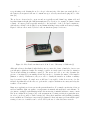
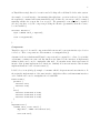
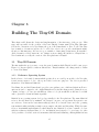
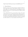
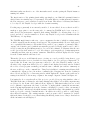
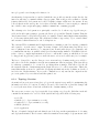
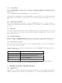
The nodes are often referred to as motes and are typically around 50mm long, 30mm wide and
less than 10mm in height (the MICAz manufactured by Crossbow for example is 58mm x 32mm
x 7mm). A battery pack is typically attached to the underside of the board and contains two
AA batteries, adding to the height by around 10mm including battery width and battery housing.
Figure 1.1 shows a mote made by Rene beside an American penny for reference.
Figure 1.1: Mote Beside an American 1c Coin. Source: University of California [4]
Although each mote has limited individual resources, a network of tens or hundreds of motes can
perform quite sophisticated tasks. For example, consider one study carried out related to intrusion
detection and tracking in a military context [1]. The motes were able to not only determine the
presence of an intruder, by measuring vibrations, but also to determine the nature of the intruder
(human or vehicle). Furthermore, they were able to classify the intruder as civilian or military
based on metal content. No single mote would have been capable of this, however use of a distributed algorithm allowed the motes to perform the complex calculations necessary and relay the
results to a base station.
Many more applications of sensor networks present themselves. For example, monitoring of factors
such as: humidity, light, air quality or temperatures in natural and man made environments. To
give just two examples, such tasks may include the monitoring of animals’ habitats to ensure certain
factors are within allowed ranges [14] or the measurement of seismic activity in a particular area,
in order to predict possible volcanic activity [20]. Given their small size and flexibility (resulting
from combinations of hardware sensors and programmed behaviour) many problems which require
sensing of some set of variables can be solved well by the use of a wireless sensor network.
3
1.1.2
Testing In Sensor Networks
One of the issues encountered when developing applications for sensor networks is testing. The
typical features of sensor networks are that they are widely distributed, often in inaccessible places
[16] e.g. embedded in buildings or in an area hazardous to humans. Given the difficulty making
changes in-situ, it is often desirable or necessary to deploy the motes just once. If this is the case
then the code must be rigorously tested prior to deployment as a coding error could be costly to
fix. For this purpose, two options present themselves: testing on real hardware and testing using
simulation or emulation.
Testing on hardware can be a difficult process for a number of reasons, which will be covered in detail
in Section 2.2. For example, as motes are designed to be small, low power and often embedded (or
otherwise inaccessible). As a consequence, they lack detailed output capabilities and so collecting
debugging information becomes more difficult. Testing is also made more difficult as sensor networks may be distributed over large geographical areas or involve large numbers of individual motes.
Software simulation has been used in the testing of sensor networks to provide some guarantees
with respect to the correctness and reliability of the code running on the motes. Simulators exist
for TinyOS which allow the user to run custom-defined topologies, the most popular of which
is TOSSIM. TOSSIM is a “discrete event simulator” designed to simulate behaviour of entire
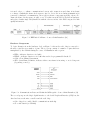
sensor networks [12]. While being an effective tool for this purpose, TOSSIM has a number of
shortcomings, as will be discussed in Section 2.3.
1.2
Aims
The project’s key goal was the creation of a testing platform for TinyOS code which would provide
accurate simulation functionality. Particularly, emphasis was placed on creating components which
would emulate the real hardware at the lowest level, as opposed to simulating the behaviour of top
level components. The result of this is as much of the real code as possible can be run, providing
a high fidelity simulation.
One of the key requirements for any test of TinyOS code is, clearly, the ability to allow nodes
within the system to interact as they would within the real sensor network. On physical hardware,
communication is achieved by the use of low power radios and the project’s test platform would
need to emulate this functionality by passing data between Xen domains.
In addition, the solution was required to enable future developers to create, and easily use, their
own radio models to affect radio communications between the simulated motes (i.e. produce bit
errors during transmission or prevent entirely communications between particular nodes). The user
should also be able to run custom topologies and be able to examine the interactions of the nodes
within them.
The project was also undertaken in order to demonstrate the feasibility of using TinyOS and Xen
in conjunction. This was a particularly interesting aspect of the project, as the two are at opposite
ends of the spectrum in terms of scale; while Xen is designed to run many large operating systems
on a computer with vast resources, TinyOS is designed for the small microprocessors found in
4
sensor motes. As a result, the two projects rely on completely different hardware, and so creating
a single solution from both source trees was an interesting task in itself.
In addition, this is the first project undertaken which uses Xen domains for simulation of sensor
networks. By testing the accuracy and scalability of the solution produced using this new method
of simulation, it would also be possible to prove whether or not the concept is useful in principle.
1.3
Document Outline
The remainder of the discussion in this report will be divided as follows:
• Project Context - TinyOS, Xen and TOSSIM (Chapter 2)
• TinyOS Domain Design and Build Process (Chapter 3)
• MICAz Hardware Emulation - removal of hardware dependencies in the MICAz platform’s software components (Chapter 4)
• Radio Communications - the design of the simulated radio chip and radio channel between
the TinyOS domains and the central radio model (Chapter 5)
• Topology Management - starting, manipulating and viewing simulations (Chapter 6)
• Testing and Evaluation (Chapter 7)
• Conclusion (Chapter 8)
Chapter 2
Previous Work
This chapter is intended to familiarise the reader with the works upon which this project is based.
The two projects upon which this is directly based will firstly be discussed: TinyOS in terms of
its existing structure and Xen in terms of the interface it requires its domains to use. The current
TinyOS simulator, TOSSIM, will also be discussed as this is the benchmark against which the
project’s simulator can be compared.
2.1
TinyOS
TinyOS is a component based, event driven operating environment designed for use with embedded
networked sensors, such as the Mica and Telos motes [5][11]. This section will firstly discuss nesC,
the language in which TinyOS is written (and which was created specifically to implement TinyOS)
and will then discuss the architecture of TinyOS itself.
2.1.1
nesC
The vast majority of TinyOS is written in nesC, an extension of C, which has a number of key
features which make it suitable for use in sensor motes, including bi-directional interfaces, components and tasks. nesC was written specifically for TinyOS and so discussing one in many cases
implies discussion of the other. This section is an introduction to the key areas of interest in the
nesC language however a full guide to nesC can be found in the “TinyOS Programming” paper by
Philip Levis [6].
Interfaces
Interfaces in TinyOS are bi-directional, specifying both the commands a component makes available
to be called and the events which it signals. Generally speaking commands will form a chain
from the application to hardware (such as sending a message over the radio). Conversely events
will occur as a result of hardware interrupts and will signal up to higher level components (for
example, notification that sending a packet over radio has completed).
Another feature common in TinyOS interfaces is split-phase operation. Typically a component will
call a function in another component and, if it is an operation likely to take some time, the caller
will wait for an event signifying the operation is complete [6]. Split-phase operations are necessary
5
6
as TinyOS has a single thread of execution and a blocking call would thus block the entire system.
An example of a nesC interface demonstrating this split-phase operation is shown below. In this
the request() command will return immediately and, in this case, an error t will be returned
signifying whether the request has been accepted. The granted() event will then be signalled
at some point later on by the component providing the interface (presumably when the resource
becomes available).
interface Resource {
async command error_t request();
...
event void granted();
...
}
Components
TinyOS is composed of re-usable components which can use and/or provide interfaces (see Section
2.1.1 above. These components are either modules or configurations [6].
A module is the most fundamental TinyOS component and is comparable to a Java object in that
each module contains some state and has functions (as defined by the interfaces it implements)
within it which can be used to manipulate that state. If a module states that it provides an
interface then it must implement those functions. Similarly if it uses an interface then it must
implement handlers for the relevant events [6].
LedsP, below, is an (abridged) example of a module which both provides and uses interfaces. It
shows just the implementation of the Init interface, which then calls several GeneralIO interfaces
each of which can be used to manipulate the relevant LED.
module LedsP {
provides {
interface Init;
interface Leds;
}
uses {
interface GeneralIO as Led0;
interface GeneralIO as Led1;
interface GeneralIO as Led2;
}
}
implementation {
command error_t Init.init() {
dbg("Init", "LEDS: initialized.\n");
...
call Led0.set();
7
call Led1.set();
call Led2.set();
return SUCCESS;
}
}
A configuration component contains no function implementations and acts as a wiring specification for other components. If a component uses an interface then a configuration must wire this
to a component which provides that interface. As a configurations contain no implementation,
then if a configuration component states that it provides an interface then it must wire this
functionality to another component. In turn, if this second component is a configuration then
the second must wire the functionality to another component and so on. Similarly, if it uses an
interface then it may wire this to a component which uses that interface [6].
Below is the LedsC configuration component which wires the interface it provides to the LedsP
component containing the real implementation. It also wires the init interface of PlatformLedsC
to that of LedsP. It then wires the interfaces LedsP uses to the implementation provided by the
platform. It is also worth noting the TinyOS convention of using C endings for components which
are public and intended for use by other developers (as in LedsC). The components ending in P (as
in LedsP) are intended for private use only and involving them in new wirings may have unexpected
results.
configuration LedsC {
provides interface Leds;
}
implementation {
components LedsP, PlatformLedsC;
Leds = LedsP;
LedsP.Init
LedsP.Led0
LedsP.Led1
LedsP.Led2
<->
->
->
PlatformLedsC.Init;
PlatformLedsC.Led0;
PlatformLedsC.Led1;
PlatformLedsC.Led2;
}
The component-based design allows for flexibility as components which provide the same interface
can be swapped easily if required. The use of configuration components also allows for the implementation to be hidden from the calling component and so changes are invisible to the caller. In
addition, while most components contain software logic, some are thin wrappers around hardware
with the distinction being invisible to the developer [6]. This separation of concerns allows developers to simply use the standard interface to perform the required task instead of making numerous
hardware-specific calls.
Concurrency
As there is only a single thread of execution in nesC, concurrency is managed by using tasks
which run atomically with respect to one another. Tasks are posted to a queue and are processed
8
sequentially by a non-preemptive scheduler. Long activities are typically divided into sequences of
short tasks to allow other activities to make progress.
While being executed, a task can be preempted by interrupts. As a consequence, state which can be
accessed by at least one interrupt must be protected by atomic sections which temporarily disable
interrupts [6]. For example, consider the following atomic section:
atomic
{
theState = newState;
}
This atomic section is transformed in the real C code to:
{ __nesc_atomic_t __nesc_atomic = __nesc_atomic_start();
StateImplP$theState = newState;
__nesc_atomic_end(__nesc_atomic);
}
Here the nesc atomic start() and nesc atomic end() functions must be defined by the platform and must disable and enable interrupts globally. Thus, atomic sections are standardised
across the different hardware implementations which exist. As an aside, StateImplP$ is the prefix
attached to all variables within the StateImplP component after translation to C. By prepending variable names within components in this way, the separation of components’ namespaces is
achieved when nesC component files are translated to a single C file (see Section 2.1.1, below).
The distinction made is between “asynchronous code” (async), reachable from at least one interrupt
handler, and “synchronous code” (sync) which is only reachable from tasks [6]. The compiler will
return an error should any sync code be called directly from async code. Should any async code
require access to syncronous code, it must post a task containing a call to that command. This
will then be scheduled to be run in a synchronous manner in the context of a task [6].
As all code inaccessible from interrupt handlers can only run in the context of a task (and all tasks
are run atomically with respect to one another) there are no concurrency issues within that code.
That is to say synchronous code does not require explicit atomic sections around state accessed by
more than one command or event. By contrast, asynchronous code does require atomic sections
around such state. In the absence of these sections interrupts may preempt any task accessing the
shared state at any time.
Compilation
The nesC compiler, in short and for a given application, operates by compiling the required nesC
components to produce a standard C file. The components are specified by the particular platform
9
for which the application is being compiled. The relevant standard C compiler (for example, avrgcc for Atmel motes) then creates the binary image to be loaded onto the mote. Using C as an
intermediate step means TinyOS can operate on any microcontroller which has a C compiler i.e.
virtually all microcontrollers currently used in sensor networks.
2.1.2
TinyOS Architecture
Platforms
TinyOS is designed to function across several mote platforms, and thus has to support a variety of
hardware. To support this the TinyOS source tree is divided into the following sections:
•
•
•
•
chips - TinyOS components for interacting with individual hardware components
system - core TinyOS functionality
lib - additional cross-platform functionality
platforms - platform specific components
Each platform in TinyOS has its own folder within platforms, and it is a requirement that the
platform provide a number of components with certain high level behaviours. Examples of these
include an LEDs component and a high level abstraction over the platform’s radio and timers.
Using these TinyOS can then ensure consistent behaviour across all platforms despite each having
different hardware.
The platform folder also defines a list of directories (in order of preference) which contain the components which are part of the platform. It can include components from any of the folders noted
above, including from the platform itself and from other platforms. For example if an application
states that it uses the “LedsC” component, then the directories on this list are searched sequentially
to find the component with that name. In the case of duplicate components, it is the first which
is taken. This approach provides a great deal of flexibility, allowing each platform to define its
own implementation of components and even allowing a platform developer to override any of the
TinyOS core components.
In addition to this, defining a new platform can be simplified if the chips on the mote already have
implementations in the chips directory. Similarly, families of motes which share a certain number
of hardware components can share any platform specific components they have in common. The
MICA family of motes, for example, all use the same ATmega128 microcontroller, and thus all
use the atm128 chip directory which contains a number of components to access the underlying
functionality the chip provides.
An application developer can then write a platform independent application and can specify at
compile time which platform to compile it for. This is done simply by running “make hplatformi”
which invokes the compilation of the application using the TinyOS toolchain using the list of components specified by that platform.
10
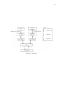
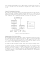
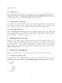
Applications
TinyOS is compiled with just one top-level application. However, there is nothing to prevent the
developer wiring this to many individual application components each having a separate function.
As described above (Section on nesC), the TinyOS compilation only includes the components the
application requires in order to minimise the amount of storage needed for the application on the
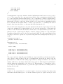
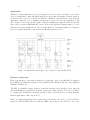
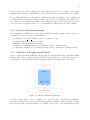
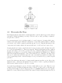
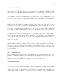
mote. Figure 2.1 shows the module graph for TinyOS assuming the application has used the RF
chip, serial port, timers, EEPROM and sensors. It shows the application using a number of crossplatform components (Application to Byte Levels) which rely on standard interfaces to hardware
provided by platform-specific components in the Hardware Interface Level.
Figure 2.1: TinyOS Module Graph. Source: Lynch, C. and O’Reilly, F.[13]
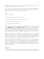
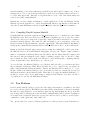
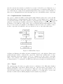
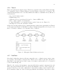
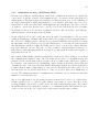
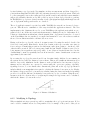
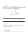
Hardware Abstraction
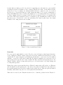
Each of the hardware components is abstracted by using three layers: the Hardware Presentation
Layer (HPL), the Hardware Adaptation Layer (HAL) and the Hardware Interface Layer (HIL) as
illustrated in Figure 2.2.
The HPL is essentially a simple wrapper around the hardware and typically provides functions
such as initialisation, starting and stopping, getting and setting registers. It is also responsible
for enabling and disabling the interrupts relevant to that component and for providing interrupt
handlers particular to that component [5].
HAL code remains platform-specific, as platform specific interfaces are used to provide useful abstractions. Whereas HPL actions are stateless, HAL components are also allowed to store some
11
Figure 2.2: TinyOS Hardware Abstraction Layer. Source: TinyOS.net TEP102 [5]
state relating to interactions with other components. [5]
HIL components are responsible for adapting the platform specific interfaces to standard interfaces.
The amount of work to be done here will depend on the capabilities of the HAL interface relative
to the requirements of the standard interface. [5]
While using the HIL ensures cross-platform compatibility, certain tasks may be much more efficient
if performed via one of the lower layers. Therefore, some components may bypass the HIL interface
and be wired to either the HAL or HPL at the cost of decreased portability [5].
For this project it is important that only low level layers such as the HPL and HAL be modified
wherever possible. This is preferred to making changes to any higher level modules in TinyOS as
more of the original code will be running in the simulation, increasing its accuracy.
2.2
Testing TinyOS Applications
In many cases once a group of motes is deployed it can be expensive, in terms of both money and
time, to make modifications to the applications running on them. The motes may, for example,
have been deployed randomly by air making them difficult to find. Alternatively the environment
may be inhospitable such as surrounding a volcano making recovery hazardous [20]. As a result
of this the motes’ applications must be tested rigorously prior to deployment. However, there are
several issues when trying to test motes in a development environment.
12
2.2.1
Obtaining Debug Information
The motes are not typically used in direct interaction with a human user and so have limited
capabilities to display information directly, for debugging purposes for example. Output is often
limited to a small number of LEDs (typically three) and obtaining enough information from these
can prove difficult. To obtain detailed information individual motes can be connected to a desktop
computer by a USB connection and have the messages that it outputs delivered to the desktop’s
screen. Alternatively a radio base station can be connected to the development machine and the
motes will deliver information by radio to the base station to be displayed on screen.
However, the above methods of obtaining data from motes have a number of disadvantages in a
development environment. The first problem is that sensor networks can involve large numbers of
motes, which would make a physical connection to a development computer impractical. This can
be overcome by using a base station as described above, but this may be inappropriate if it is the
radio which is being tested.
2.2.2
Simulating Field Conditions
A second consideration when testing applications for sensor networks is ensuring the test properly
simulates the conditions in the field which may impact the behaviour of the system. This may
include physical distance between sensors, radio interference or events such as nodes failing as a
result of, for example, running out of battery power.
When developing an application it may be infeasible to have a topology of motes set up as they
would be in the field. The distances involved may simply be too large, as in one study measuring
volcanic activity where the network spread over five kilometres [20]. Alternatively, the developer
may require many random topologies to be tested as if the motes were dispersed from a moving
vehicle; physically rearranging the motes for this purpose could prove prohibitively time consuming.
In addition to the above, the motes may need to use a sensor to detect an environmental factor
which it is not possible to manipulate easily in a development environment such as humidity or
concentration of a particular gas. While the developer could modify the application to use fake
values instead of using the sensor, this introduces scope for error as the developer is forced to run
code in testing which is different to the code which is deployed. Providing the facility for this in
the testing environment removes the responsibility from the application developer, allowing them
to focus on their core task.
2.3
TOSSIM
TOSSIM is the simulator for TinyOS applications most widely used by TinyOS application developers. It aims to overcome some of the limitations of testing within a development environment
(as discussed in Section 1.1) by providing a “high fidelity” simulation of large networks (up to one
thousand) on a single x86 desktop machine [12].
TOSSIM relies on nesC compiler support in order to replace certain components with TOSSIM
implementations. Specifically, if the “sim” flag is provided to the compiler then any directory
13
specified by the platform as a source for components is preceded with the “sim” folder within that
directory when the nesC compiler searches for a component with a given name. This causes any
TOSSIM implementations to be found first by the compiler and used instead of the real components.
2.3.1
Advantages of TOSSIM
TOSSIM clearly overcomes the initial physical constraints encountered when testing a real network
of motes as networks spanning unlimited distances (in practice) can be tested in the development
environment. More importantly TOSSIM uses simple topology files to define networks i.e. which
nodes can see each other and how strong the radio links are amongst them. Tools can be used to
create a desired topology or to create a random network thus dealing with the issue of setting up
physical networks mentioned in Section 2.2.2.
Secondly, in terms of gathering debug output from the simulated motes, TOSSIM provides a single
console to which all nodes can print detailed information; this is in contrast to the limited output
capabilities of the hardware motes and allows a developer access to the motes’ variables at a given
point in time.
Thirdly, TOSSIM provides high fidelity radio simulation (at the bit-level [12]) with a number of
models available each affecting the radio communications in a particular way. Bit error probabilities
and distances between nodes can, for example, be specified. A number of Java and python-based
tools also exist to create and monitor network topologies which simplify management of simulations.
A fourth benefit of using TOSSIM is that it is well integrated with the normal TinyOS build
toolchain with just a few alterations. Compiler support allows the user to merely append “sim” to
the normal “make MICAz” command in order to make the TOSSIM implementation of the MICAz
platform (currently the only platform supported). This integrated approach is preferable as it does
not require the user to learn a new way of compiling their TinyOS applications.
2.3.2
TOSSIM’s Imperfections
It has been noted, however, that TOSSIM has a number of imperfections [12]. Code running in
TOSSIM will appear to run instantaneously and interrupts, for example, while timed exactly, will
never interrupt running code; as a result of this TOSSIM interrupts are also non-reentrant which
is not the case when running on hardware. This imperfection arises from the fact TOSSIM is a
“discrete event simulator” in which each TinyOS mote has its own queue of events which includes
incoming radio packets and timer interrupts. Events are popped off the queue and processed at
discrete intervals causing the relevant code to be executed on the mote. The time taken for each
event to be executed, however, is not simulated and will appear to run instantaneously.
Due to this event-driven approach an interrupt which will cause incorrect behaviour in a physical
mote may not cause the same error in the simulation. For example, an interrupt may modify some
variable while normally executing code was in the middle of reading the variable. This can never
occur in the TOSSIM mote and so such an error would not be detected. For the same reason, any
code which performs an infinite loop waiting for an interrupt to occur will never terminate in the
14
simulation.
Another limitation of TOSSIM is that it is only possible to run a single application in the simulated
sensor network. In real sensor networks, many different applications may be running which may
interact deliberately or accidentally, and it would be useful to simulate this. When writing applications for testing with TOSSIM developers are often forced to insert conditional blocks to make
nodes exhibit different behaviours; the node with ID number zero may, for example, be the sink to
which the other nodes send data and each node must check at start up which ID it has in order to
execute the appropriate code. This results in the code that is written for the simulator differing
from the code that would be written for the real hardware, creating a source of inconsistency and
error.
As noted in the above section TOSSIM currently only provides simulation for the MICAz platform.
TinyOS’s platforms are expected to provide similar functionality via a set of standard interfaces
(for timers, radio etc.) and so this is often not an issue. While this is true in many cases, there are
of course instances where testing on the MICAz is insufficient and thus other methods of testing
will be required.
The Xen Meets TinyOS project is designed to overcome some of these limitations in the TOSSIM
concurrency model and its inability to run heterogeneous applications in a network. At the same
time the project’s solution will be able to provide similar advantages to TOSSIM, including complete
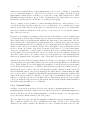
toolchain integration and simple creation of network topologies.
2.4
Xen
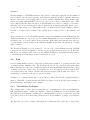
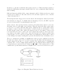
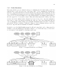
Xen is a virtual machine monitor (or hypervisor) which allows a number of operating systems to run
on a single machine simultaneously. The Xen hypervisor is the only element in the system which
runs on hardware as each of the operating systems in the system run within virtual machines, called
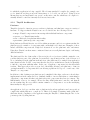
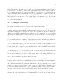
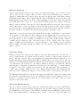
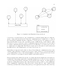
“domains” in Xen (See Figure 2.3). Xen regulates access to the physical resources such as CPU
cycles and memory and ensures domains cannot interact inappropriately with each other i.e. by
attempting to read memory allocated to another domain.
A number of operating systems have been modified to run as Xen DomU domains including a
number of Unix-like operating systems and Windows. Figure 2.3 shows the hypervisor running on
physical hardware, managing several domains.
2.4.1
Virtualisation Technique
The technique used to achieve this is a particular type of virtualisation termed paravirtualisation.
Full virtualisation aims to emulate the hardware completely, making the guest OS unaware that
any abstraction from hardware is taking place. Paravirtualisation, however, requires the guest OS
be modified; Xen’s creators state that porting the OS to Xen is similar to porting to new hardware
[9].
The hypervisor provides a software ABI (application binary interface) made up of “hypercalls”
15
Figure 2.3: Xen Running Dom0 and Several DomU’s
which replace the standard system calls; this includes, for example, privileged instructions such as
updating page tables and requesting access to hardware resources. Although this requires development time to be spent changing the original hardware calls to hypercalls the technique yields
considerable increases in performance over alternative virtualisation approaches (up to a factor of
ten [8]). It should be noted that only the OS requires any modification and that user applications
remain unchanged [9].
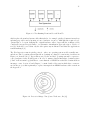
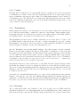
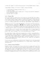
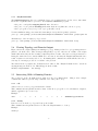
The Xen hypervisor runs in privilege ring 0 - where an operating system would normally run and the modified operating systems (known as domains) are changed to run in ring 1 as shown in
Figure 2.4. As stated above, hypercalls are used by the modified operating systems to request access to hardware via the Xen hypervisor. In order to manage physical interrupts, domains register
(“bind” in Xen terminology) handlers to event channels on which Xen notifies the domain when an
interrupt occurs. Section 4.5 and Chapter 5 contain details of the ways in which these events are
used in the project; this is primarily to replace interrupts from MICAz hardware with events from
the hypervisor.
Figure 2.4: Protection Rings - Xen (Source XenSource, Inc [8])
16
2.4.2
Domain Management
A single, specially privileged domain (“Dom0”) is the first domain the hypervisor loads when booting; this is typically a modified Linux kernel. This domain has access to available hardware such as
hard disks and network interfaces. Other domains (termed “DomU” or guest domains) do not have
direct access to these resources and must request access via Dom0 but the distinction is transparent
to all but the lowest layers of the operating system.
Guest domains are started from Dom0 by using the xm command. This command covers essentially
all aspects of domain management such as creation, pausing, destroying, monitoring and modification of domain variables. For example, to destroy a new domain the xm destroy <domainid> sub
command is used. xm is a privileged command and, thus, requires the user to have root access.
When creating a domain a config file must be specified as an argument to the xm create command.
This specifies a number of domain-specific details such as its maximum memory usage, the network
bridge to which its network interface will be connected (allowing for communication with other
domains on a shared network bus) and the domain’s name.
2.4.3
Split Drivers
As guest domains do not have access to the physical hardware, their device drivers are replaced
with a split driver implementation. The backend portion of the driver resides in Dom0 and accesses
the hardware resource. There will be many frontend instances of the driver, one in each guest domain; it is for this reason the lower layers of the guest OS’s drivers must be modified. Using this
frontend-backend implementation, guest domains can request access to a resource such as to send
an Ethernet frame over a network interface. Conversely guest domains can be notified of incoming
events, for example, a new Ethernet frame with that guest’s MAC address in the destination field.
Although Xen provides a useful network-like interface for communication between domains the
underlying method is shared memory to transfer data. Events are sent from one domain to another
to notify the receiving domain that new data is available in shared memory.
Using this method of split device drivers allows for sharing of physical resources and is used in the
project particularly to transfer simulated radio frames between domains (as described in Chapter
5).
Chapter 3
Building The TinyOS Domain
This chapter will discuss the design and implementation of the first stage of the project. This
stage was responsible for the creation of the basic TinyOS domain, named XenoTiny; this name
follows the convention set by XenoLinux, the port of the Linux kernel to Xen. To the XenoTiny
base a number of features would need to be added, in order for it to provide useful functionality.
Creation of this first stage did, however, pose a number of interesting design issues. It is useful to
divide discussion of these issues into two distinct sections: firstly, the insertion of TinyOS into a
Xen domain and secondly, the creation of the Xen platform for TinyOS.
3.1
TinyOS Domain
The first task in the project was to create the guest domain in which TinyOS would be run, as per
Figure 2.3. It was required to make modifications to TinyOS similar to the changes made to Linux
to create XenoLinux.
3.1.1
Reference Operating System
In the absence of a formal document which specifies how one would port an OS to the Xen platform it was necessary to look to other ported OSs for reference purposes. Two choices presented
themselves: XenoLinux and Mini-OS.
XenoLinux, the modified Linux kernel, provides some guidance as to which modifications Xen requires as it can be compared to the original Linux kernel to find the changes made. Linux, however,
consists of a large code base (several millions of lines of code) from which it would have been difficult to glean the relevant information quickly.
Mini-OS is an operating system developed specifically for the Xen platform. The name Mini-OS
refers to the fact that it is a “minimal” OS designed - in part - as a specimen Xen guest for use
as a reference. It meets the basic functionality specified above but also has some basic operating
system functionality including a simple non-preemptive scheduler and threading. While the name
refers to its minimal implementation, rather than its size, Mini-OS does have a small code base
with fewer than ten thousand lines of code. As Mini-OS was designed to be a reference for other
developers this code is laid out in a clear manner which aids understanding. Although Mini-OS was
17
18
created as a specimen Xen domain it is also fully functional - there is, for example, a Java virtual
machine implementation for an augmented version of Mini-OS in development at the time of writing.
Despite Mini-OS having no real hardware equivalent and, thus, providing no way to quickly find
sections which were written specifically for Xen, it was decided to use Mini-OS as a primary reference. This decision was taken principally because Mini-OS is targeted - at least in part - for use as
a reference and secondly, the volume of code was much more manageable in the time available.
3.1.2
Necessary Domain Functionality
From examination of Mini-OS it became apparent that the TinyOS domain would be required to
perform the following to get the domain running:
•
•
•
•
•
reading the start info t struct provided at domain boot-up
setting up handlers for virtual exceptions
handling events such as timer interrupts
a method of communicating between domains (for radio communications)
compilation of TinyOS to an elf binary (as used by Xen to start guest operating systems)
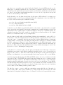
3.1.3
Mini-OS as a Wrapper around TinyOS
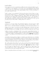
It also became apparent that Mini-OS contained almost exactly the same start-of-day functionality
which would need to be implemented in XenoTiny. In fact just a few of Mini-OS’s features were
not applicable for TinyOS such as threading functionality and dynamic memory allocation.
Figure 3.1: TinyOS as Mini-OS application
For these reasons, and so as not to duplicate code, it was decided to run TinyOS as Mini-OS’s
application. This had the added benefit of making available a number of functions which encapsulate Xen hypercalls. A sleep() function, for example, used in place of two individual hypercalls.
19
An understanding of how hypercalls interact with Xen was still required: firstly, some of these
abstractions are close to the real hypercalls and secondly some new functionality would need to
be added using hypercalls. This said, development time for some of the basic functionality was
reduced as a result of using Mini-OS.
Mini-OS also provides a simple mechanism to compile application code into the Mini-OS domain.
Mini-OS expects an application to override its app main() function. app main() is called immediately after domain initialisation and the domain terminates when the application terminates.
3.1.4
Compiling TinyOS Against Mini-OS
Normally Mini-OS expects the application’s app main() function to be contained in a .c file within
the Mini-OS folder. As Section 2.1.1 notes, the TinyOS compilation process does produce a standard C source file however that C file is typically compiled in isolation and therefore contains a
standard C main() function. The solution to this was simply to use a sed script to replace the
main() declaration with the Mini-OS compatible app main(). Thus when Mini-OS has finished
setting up the domain TinyOS’s main() function will be called as it would be on the real hardware.
Having modified the TinyOS entry point it was hoped that the resulting file could be placed into
the Mini-OS directory and build Mini-OS using make. However, the TinyOS output contains a
number of redundant declarations which cause the build to fail. Modifying TinyOS’s output would
have involved either modifying the nesC compiler or writing a script to run over the file to eliminate declarations. Both of these methods would have been prohibitively time consuming with the
former, in particular, being outwith the scope of the project.
To solve the issue, the Mini-OS build process could have made its call to gcc less strict and allow
these redundant declarations. While this would allow the code to compile it also encourages less
tight coding in Mini-OS which is undesirable. Instead, the TinyOS C file is compiled to a .o object
file (the details of the TinyOS build process to create this object file are contained in Section 3.2)
which is then included in the Mini-OS build. While this does require the Mini-OS Makefile to be
modified to a lesser degree, it is a small change to simply add the TinyOS object file to the list of
object files used to produce the final Mini-OS binary.
3.2
Xen Platform
It was desirable that the build process for the Xen testing environment be as similar to the build
process for real motes and for TOSSIM. It was realised that porting TinyOS to Xen was essentially
the same as porting TinyOS to a new hardware platform. By implementing the Xen port in this
way, it was possible to integrate the solution with the existing TinyOS build toolchain. Compilation
as a result, is also identical from the user’s perspective and it would be possible to merely replace
commands to “make hplatformi” with “make xen”.
Two options existed for creation of this new platform: it could represent a generic TinyOS mote,
20
replacing top level functionality, or it could be specific to a particular set of hardware and replace the
low-level functionality. Given the project’s aim to create an accurate simulation of mote behaviour
the latter was the obvious choice. This more in-depth implementation would be highly accurate for
the chosen platform and provide reasonable guarantees of correctness for other platforms (as the
TinyOS architecture ensures that different motes provide a standard set of high level behaviours,
see Section 2.1.2). This is the same approach taken by TOSSIM, which bases is simulation on the
MICAz platform but modifies more of the original TinyOS code than this project. In order that
the Xen testing environment would match with TOSSIM’s existing functionality, the MICAz was
also used as the base platform.
3.2.1
Creating the Xen Platform
To get to the point where a user could run the “make xen” command from an application’s directory a number of additions needed to be made to the TinyOS make system.
Firstly, the xen directory within the TinyOS platforms directory was created. The TOSSIM style
of adding “sim” directories within the real implementation directories was used; wherever a Xen
implementation was required it was placed in a“xen” directory within the directory containing the
original component. The xen platform directory, therefore, only contains a list of directories which
contain the components required to build it. The “xen” directory in this list, if one exists, is placed
before each original directory ensuring the Xen implementations are chosen by the compiler. This
requires each new “xen” directory created be added manually to the list but results in a compilation
process virtually identical to compilation of any other platform and is still in keeping with the file
structure with which users and developers of TOSSIM are familiar.
The above changes allowed the correct nesC components to be included in the building of the Xen
platform by the nesC compiler. The next step was to modify the make process to produce output in
a format which could be compiled together with Mini-OS (the method by which TinyOS is actually
included in the Mini-OS build is discussed in Section 3.1.4).
The “make hplatformi” process automatically looks for a set of platform specific makerules in a
location within the TinyOS source tree. In order to include the compilation stages particular to
Xen a new set of makerules were added to this location. Many of the existing makerules for the
mica family of motes (based on Atmel’s ATmega128L microcontroller) could be reused for this
purpose, however a number of modifications were necessary.
One of the key changes required was the removal of references to the AVR libraries and header
locations. These were then replaced with Mini-OS’s header locations. This would ensure that whenever TinyOS performed a strcpy() operation that it would be the x86 Mini-OS version which was
called. This was particularly important as the AVR libraries could not be guaranteed not to contain
assembly code which would fail either to compile or run on non-AVR hardware. Fortunately both
the AVR and Mini-OS libraries followed quite closely the C Standard Library headers format so
just a few workarounds were required to successfully compile TinyOS with Mini-OS’s headers.
In addition to this, a further stage of compilation was appended to the end of the Make process.
After ncc (the nesC compiler) had produced the standard C file, gcc (the x86 C compiler) is run.
21
The C file is provided as its input in order create the object file which Mini-OS expects. Thus, the
compilation of TinyOS for the x86 platform (as required to run within Xen) is achieved.
3.3
Physical Resources
Attempts have been made in areas to simulate the physical resources available, such as CPU cycles.
Xen provides functionality to limit the percentage of the CPU a domain will be given. However,
as Xen is designed for relatively few, large OSs the minimum allocation unit is one percent. As a
result, on a 2GHz processor, each simulated mote will have a virtual 20MHz CPU. Of course, this
is a 32bit x86 processor, as opposed to a 8bit RISC processor (as used on the MICAz, for example).
While this is less than ideal, it is the best possible simulation using the facilities Xen’s domain
management tools provide.
In terms of limiting simulated memory to the motes, this is not required to achieve accurate
performance simulation. The reason for this is that TinyOS has no dynamic memory allocation
or virtual memory. Thus, if the compiled TinyOS program will fit within the mote hardware’s
memory, then there is no disadvantage to allocating extra memory in the Xen simulation. As a
result, it suffices to limit the domains to the minimum size in which they will run, as any excess
memory will not be used and, thus, will not affect the simulation’s performance. However, it should
be noted this allows the possibility that the TinyOS program on Xen may not fit on the physical
mote. Developers should therefore check the real compiled size of a program in the output produced
by the MICAz compilation process to ensure their applications will fit on the hardware.
Chapter 4
Basic Functionality
The previous chapter discussed the stage of the project concerned with building the TinyOS domain. However, it is really a high level description of how the build process is carried out; as such
the modifications in the previous chapter alone are not sufficient to allow TinyOS to compile and
certainly not to run its main() function. Particularly, TinyOS still relied on the hardware for which
it which it was originally designed, referencing registers and pins which clearly do not exist on the
virtual x86 hardware which Xen presents to its domains.
This chapter will firstly describe the fundamental changes to these hardware calls which needed to
be made. It will go on to describe the more complex hardware components such as the timer and
LEDs which had their functionalities emulated.
4.1
Registers and Pins
Chapter 3 describes the process of changing the build process to compile to an x86-compatible
executable. TinyOS’s components for the MICAz platform, however, contain references to the
hardware registers and pins. These had to be replaced in order to run on the x86 platform.
4.1.1
MICAz Implementation
The MICAz’s Atmel AVR microcontroller uses memory-mapped I/O for its pins and registers; the
microcontroller reserves a number of low memory addresses specifically which can be accessed in
order to read the status of a pin/register or manipulated in order to affect a pin/register. This
method is completely incompatible with the Xen platform for a number of reasons, not least of
which is that the memory addresses used in a Xen domain are virtual. Thus, if the TinyOS domain
attempted to access low memory it would almost certainly be an invalid address resulting in the
hypervisor destroying the domain. Perhaps more obviously the x86 architecture does not have the
same register set-up as the mote hardware and so, even if the calls could be made, they would not
have the desired effect.
As the hardware elements are memory-mapped the AVR libraries include definitions such as
PINA..PINH which can be used in TinyOS code as an easy-to-remember replacement for the ab-
22
23
solute memory addresses. Developers can then use these to interact with the hardware using the
same techniques as manipulating a regular variable.
Code written for the MICAz sometimes relies on the fact these memory locations are in low memory.
The following code is contained in one of the low level components which handles interrupts from
the microcontroller: uint8 t addr = (uint8 t)&EICRA. This explicitly casts the memory location
of the EICRA register to be an unsigned eight bit integer. This addr variable can then be used to
create a pointer to the register as follows: (uint8 t*)addr. This is perfectly valid when it can be
guaranteed that the memory address’s absolute value is less than the maximum value held in eight
bits (i.e. less than 256). On Xen any code which relies on such a cast must be replaced as there
is no way to guarantee the memory address of the simulated implementation will fit completely in
eight bits (and typically it will not).
4.1.2
Xen Implementation
Manipulating pins and registers on hardware may cause some change in behaviour to occur. To
simulate this, one solution to this which was considered was to replace the pin/register definitions
with functions. These functions would not only set or clear bits in memory but would also be
able to trigger some additional events to occur as required. This would, however, require all low
level components to have their code modified on an individual basis; the assignment PINA = 0, for
example, would have to be replaced with PINA FUNCTION(0). As pins and registers are used widely
in different components this process would be error prone. It would also be difficult to completely
automate as any script would need to take into account that PINA = 0 may not appear verbatim
in the source code. As a result, it was deemed preferable to implement any changes in a central
location, even at the expense of automatically triggering any events to occur.
The developers of TOSSIM had encountered the same problem when creating their simulated hardware. The solution they used was essentially to replace the fixed memory addresses with an array
of the same number of bits. Definitions for the pins/registers are then replaced with references into
this array. In TOSSIM this is actually modelled as a two dimensional array indexed by mote ID
and register number as a single compiled TinyOS is used to house state for all motes. Each byte
in a mote’s array represents a single register or pin on the ATmega128 processor.
In the Xen implementation this two dimensional array is not required as each mote in the system
contains its own state in a separate TinyOS instance however much of the code is reused. Specifically reused are the array and pin/register definitions which was useful as the MICAz has over 150
register and pins which would have made replacing its definitions tedious and error prone. As a
result of using this array to replace the registers/pins, any effect setting a pin or register should
have (other than simply modifying the relevant bit in the array) must be performed explicitly.
While this means the effects of these register manipulations are no longer automatically performed
when the bits are set/cleared, there are some advantages. Take, for example, a pin which triggers
some calculation on the simulated hardware which would be performed virtually instantaneously
on real hardware. An example of this would be a hardware timer which can be reset in a single
operation, where the simulated timer will have to recalculate when the next timer event should
occur and reschedule the timer interrupt. If the pin/register will be modified frequently in a short
24
time it is an advantage to be able to run that calculation just once when the final value has been
determined; this gives greater control over the timing accuracy of pin/register manipulating operations.
Because in TOSSIM many copies of a register exist (one copy per mote) a distinction is made
between the actual variable and the variable identifier. The actual variable within this array is referenced by the register or pin name. The register identifier is the index of register in the array and
is prefixed by ATM128 . For example ATM128 PINF is defined to be the value 0x00 whereas PINF is
defined to be the array element indexed by 0x00 (atm128register[0x00]). Thus if normal MICAz
code passes the value of &PINF as a small integer then this is replaced with ATM128 PINF and then
the code which uses this integer is modified appropriately to index into the array (by use of macros).
This also overcomes the MICAz’s reliance on low memory locations as references to memory location
PINF in MICAz-specific code, for example, can be replaced with an index into the array at location
ATM128 PINF in the Xen implementation. This strategy was used in the Xen project solely for
this second benefit of eliminating reliance on the pins/registers being in low memory when passing
references between low level functions.
4.1.3
Atomic Sections
Atomic sections in TinyOS are delimited by the functions nesc atomic start() and nesc atomic end()
whose implementations are platform-specific (see Section 2.1.1 for a fuller description). On the MICAz this causes a specific bit on the SREG register to be set and cleared to globally disable or enable
interrupts.
In Xen disabling interrupts is done within the domain by modifying the value of a variable within a
“HYPERVISOR shared info” which the hypervisor can inspect before signalling any virtual interrupts to the domain. Mini-OS provides useful macros for this process, allowing for the replacement
of a number of lines of code with a single call to one of local irq enable(), local irq disable(),
local irq save() or local irq restore().
local irq enable() and local irq disable() simply perform on/off transitions. In conjunction
local irq save() and local irq restore() firstly save the interrupt state before disabling interrupts and then restore them to their previous state (which may have been either on or off).
As atomic blocks within TinyOS code may or may not be nested the save/restore model is the
correct one to use. To this end the nesc atomic start() and nesc atomic end() functions
were modified from the MICAz versions to include calls to these Mini-OS macros, thus affecting
the interrupts from Xen and making the relevant sections truly atomic.
4.1.4
Atomic Pin And Register Manipulation
On the MICAz all reads and writes to and from memory-mapped registers and pins are atomic by
default. In TOSSIM, because interrupts never interrupt running code and as TinyOS has a single
thread of execution, all modifications to the pins and registers are effectively atomic. However,
in the Xen implementation reading and writing to the array representing these pins and registers
25
would not be atomic. If an interrupt occurs while the main thread of execution is in the middle
of a read or write and the interrupt reads or writes to the same location, for example, consistency
problems may arise.
To resolve this, the various macros which are used as substitutes for bit operations on the registers
and pins were made atomic by placing each within its own atomic block. This handled most of the
cases where the registers and pins were manipulated, leaving just a few direct reads and assignments
from and to registers to be changed on an individual basis. These remaining few were detected by
the nesC compiler, which warns of non-atomic accesses to shared variables. In this way it could be
guaranteed that no non-atomic reads or writes existed and that any which are added in future will
be detected.
4.1.5
Interrupt Pins
The ATmega128’s chips directory has a useful software abstraction (HplAtm128GeneralIOPinP)
over its individual pins which allows for the use of standard TinyOS calls to get, set and toggle pins.
With the modifications to the memory locations of registers and pins completed these commands
would work exactly as on hardware. The setting of a pin, as mentioned in Section 4.1.2, would
have no physical effect, particularly a problem when that pin triggers an interrupt.
The ATmega128 component set also has an abstraction over general purpose interrupts produced
by the above-mentioned GeneralIOPins - HplAtm128InterruptC - which is actually made up of
several HplAtm128InterruptPinP modules. InterruptC allows for a number of commands to be
used to enable, disable and set the edge on which to trigger interrupts. InterruptC relies on
HplAtm128InterruptSigP whose sole purpose is to contain the interrupt handlers as C functions.
Each of these handlers is a simple passthrough which signals the interrupt to HplAtm128InterruptC.
Thus, by wiring to HplAtm128InterruptC, other components can use standard nesC wirings to receive interrupts which occur at the hardware level.
On Xen, the wrapper around each pin (InterruptPinP) is augmented to also provide the XenPinEvents
interface which contains the modified() command. Each HplAtm128InterruptPinP is also modified to use this XenPinEvents interface. Particular HplAtm128InterruptPinPs can then be wired
to particular HplAtm128GeneralIOPinPs, as specified by the platform. The end result of this is
that when an interrupt-causing pin is modified, the GeneralIOPin signals its modified() event.
This is received by the InterruptPin (as if the interrupt had just occurred) and processed as normal.
When the interrupt event has finished processing, control is returned to the call which modified
the pin.
4.2
Debug Output
As described in Section 2.2.1 one of the benefits of simulators such as TOSSIM is the ability to
print debugging information to console. This overcomes the limitations of typical motes’ three
LED interfaces during develpment of TinyOS applications. In addition, this debugging functionality could also be used to aid development of the Xen platform in a similar way. Implementing
26
this functionality was therefore one of the first tasks carried out after getting the TinyOS instances
running in domains.
The first iteration of the printing functionality was simply to use Mini-OS’s printk() function
which behaves in a similar way to C’s printf(). The main difference is that printk() outputs to
the Xen emergency console which is accessible from Dom0. This allows for arbitrary information
to be relayed to the TinyOS developer while the domain is running.
For this purpose printk() is an extremely useful tool; it was realised, however, that it would be
much more appropriate to use the same style of command as TOSSIM used for two reasons: to
make Xen’s debug statements compatible with existing TOSSIM code, allowing that code to be
reused, and also to ease the transition to Xen for any TinyOS developer who is familiar with the
TOSSIM way of doing things.
The TOSSIM dbg() function takes two or more arguments, the first of which is a string stating
on which output stream the message should appear. The arguments which follow are then passed
on to a printf()-like function. Given this it was possible to use a number of printk() calls to
output to the domain’s console (with the stream name prepended). Each domain’s console could be
viewed by using the xm (Xen Management) tool’s console subcommand. To illustrate this, the user
would open a new shell, switch to root (to allow them to perform privileged domain management
commands) and then enter xm console <domain>. This shell would then display all of the output
from the domain until the shell was closed.
This method, however, would limit the user to viewing one console per shell, forcing them to open
as many shells as there were nodes which for a large number of nodes could prove impractical. To
remedy this, the Dom0 control program was connected to all of the TinyOS domains’ consoles,
allowing for the output from all the nodes to be gathered and displayed in a single window. Behind
the scenes, a Java program essentially performs the same command (xm console <domain>) as
the user would type on the command line. Using Java’s facilities for running run arbitrary shell
commands the output produced from these commands (the debugging info from the domain) is
then collected and piped to a Java swing window which displays the output together with a note
stating from which node the message originates. An example output is contained in Figure 4.1.
Performing the above steps has allowed the project to provide debug reporting similar to that of
TOSSIM. At the time of writing the only feature missing is the ability to select which output streams
are delivered to the Dom0 console (instead all are displayed). This functionality, however, would
not be difficult to implement: the start of each line of output (which contains the stream name
in the Xen dbg implementation) from the domains could simply be parsed to filter out unwanted
streams. The user could then specify which streams to attach at the start of the simulation, possibly
in the topology file or via the command interface. In addition it would be possible to easily change
these filters at run-time. The existing run-time control program could be augmented to include
this in the future. It should be noted that lacking this filtering feature is not a major drawback as
all the information is still displayed.
27
Figure 4.1: Collected Output From Running TinyOS Domains
4.3
LEDs
Most motes, including the MICAz, have a user interface consisting of just three LEDS. TinyOS requires that each platform provide a PlatformLedsC component which must provide three GeneralIO
interfaces (one per LED). Each of these interfaces provides simple set/clear functionality for each
of the pins controlling an LED. TinyOS then uses this basic functionality to create the platformindependent component, LedsC which wires its functionality to LedsP. LedsP provides some additional functionality such as toggle operations and specifying all three LEDs states with an integer
representation using the basic on/off commands provided by PlatformLedsC. This wiring arrangement is shown diagrammatically in Figure 4.2
Using the Xen registers implementation the original MICAz LEDs module would work correctly i.e.
the relevant bits would be set correctly. None of these changes would be visible to the user, however,
unless the LEDs’ states were read and printed explicitly. The obvious solution was to replace the
component responsible for manipulating the pins, and insert code to print out the changes as they
occur. Having already implemented a dbg() function for Xen, it was logical to reuse the TOSSIM
implementation which, each time a call to the LEDs component is made, manipulates the relevant
bits and then outputs any change made. This is done in LedsP, as opposed to PlatformLedsC
as the latter is actually just a configuration which wires the interfaces it provides to components
which wrap around the physical pins.
28
Figure 4.2: TinyOS LedsC
4.4
Microcontroller Sleep
Each TinyOS platform must include a McuSleepC (Microcontroller Unit Sleep) module which is
responsible for firstly, measuring power usage of the mote and, secondly, providing a command to
sleep the microcontroller.
Power measurement is done by checking a number of control registers to determine which components are active in the system. Different combinations of components result in a number of different
power states each of which consumes a particular amount of power. Using this information other
components can determine whether the system is still active or is idle and can be put to sleep.
Sleeping puts the mote’s microcontroller into the lowest power state possible, allowing battery life
to be extended substantially [15]. This is used when the TinyOS scheduler finds it has no tasks in
its queue and, thus no more work to perform. The sleep command is different from a high-level
language sleep in that it does not take the duration as an argument; the MICAz’s sleep command
instead sleeps until an interrupt has occurred. Given that the sleep command is only issued when
there are no tasks in the scheduler’s queue the only event which can result in new tasks being
posted is an interrupt. In the event the interrupt does not post a task, the sleep operation is again
performed.
On the Xen architecture this method of using assembly instructions will not work. Even if the
instruction was to exist in the x86 instruction set, it would no doubt be a privileged instruction
which a guest domain would not be allowed to perform.
As a result, hypercalls must be used to block the domain until an event occurs. This is done via
a function provided by Mini-OS which issues first a request for a timer, and secondly issues the
block hypercall. In this case the blocking is specified to be FOREVER which is some very long time
(hundreds of years). Thus, the hypercall will only return following a virtual interrupt from Xen, in
29
the same way as the MICAz’s sleep instruction only returns following a real interrupt.
4.5
Timers
This section discusses the implementation of the emulated versions of the MICAz hardware timers.
Section 4.5.1 will describe timer requirements a TinyOS platform must meet while Section 4.5.2
describes how the MICAz satisfies these requirements. Section 4.5.3 will then cover the timer
functionality Xen provides, before discussing the solution which was implemented in Section 4.5.4.
4.5.1
TinyOS Timers
Every TinyOS platform must implement a millisecond timer component, HilTimerMilliC; the
“Hil” prefix means it is the top level of hardware abstraction (as described in 2.1.2) which provides
standardised functionality using a platform-specific implementation. An abbreviated version of the
key functionality in the interface this component provides is as follows:
interface Timer<precision_tag>
{
command void startPeriodic(uint32_t dt);
command void startOneShot(uint32_t dt);
command void stop();
event void fired();
command uint32_t getNow();
}
On every platform this includes commands such as startOneShot(uint32 t dt) where dt is the
number of milliseconds after which a single fired event should be signalled. Similar commands
exist for starting and stopping periodic timers. In addition it provides a method to find out how
much time has expired through its getNow() command.
4.5.2
MICAz Timers
The above-described millisecond timing is the absolute minimum timing functionality a platform
must provide and, therefore, the only functionality of which TinyOS’s core and library components
can assume to be present. There is no such restriction on non-OS components and both applicationlevel and platform-level. The MICAz’s platform, for example, contains the CC2420 radio chip which
has its own associated chip-specific set of components, some of which rely on a 32KHz timer. It is
the MICAz’s responsibility to wire these dependencies to its own implementation. The MICAz’s
microcontroller (the ATmega128L) has a total of four hardware timers. Of these, two are actually
used on the MICAz platform: Timer0 (8 bits) for its millisecond timer and Timer1 (16 bits) for its
32KHz timer.
4.5.3
Xen Timers
Xen provides functionality to schedule timer events to be delivered to the guest domain. Requests
are made via the set timer op(timeout) hypercall which will deliver a virtual timer interrupt
30
after the timeout time (in nanoseconds) has been reached. It should be noted that just one of
these requests can exist at a time and so a new request will replace one which is pending. As a side
note: in the interest of clarity, Xen’s virtual interrupts will be called “events” for the remainder of
this section to distinguish them from the interrupts expected by the MICAz software components.
4.5.4
Implementation Considerations
One option to emulate the millisecond timer functionality TinyOS requires was to replace the MICAz implementation of HilTimerMilliC. This would have been the simplest way to emulate the
necessary functionality as calls to this would have been a pass-through to Xen’s set timer op(timeout)
with some conversion between milliseconds (as used by TinyOS) and nanoseconds (as used by Xen).
Modification of the HIL layer, while being correct as a TinyOS platform implementation, would
have been less accurate as a simulation of the MICAz’s behaviour, as there are a number of intermediate components each with their own logic which it is better to run, rather than replace.
Figure 4.3: MICAz Timer Layers
As Figure 4.3 illustrates, the millisecond timer is ultimately based on the hardware Timer0, after
passing through a number of intermediate components. Timer1 has a similar stack of components, abstracting away from hardware, at the top of which are the radio-related components.
Thus, to leave as many of the original components in the XenoTiny implementation as possible,
modifications had to be constrained to the HPL layer which acts as a wrapper around the hardware.
4.5.5
Timer0
The requirements for the timer were gathered from a combination of the ATmega128 datasheet
and the existing HPL component for Timer0. In the case of any discrepancy between the two, the
HPL implementation’s version of events was used. This was because, given that the HPL code is
well tested and performs correctly, any difference was likely to be a workaround to correct for the
hardware’s actual behaviour differing slightly from the datasheet’s specification.
31
Hardware Behaviour
Timer0 on the MICAz’s microprocessor can fire two different interrupts, one for a timer overflow
and one when a given “compare” value is reached. Each of these interrupts can be enabled or
disabled by setting values in a control register. At each clock tick the value of the timer register 0
(TCNTO0) is incremented. This continues until the value in TCNTO0 is equal to the value of the
OCR0 (Output Control Register 0). If the compare interrupt is on then the compare interrupt will
fire and the timer will be reset to zero. If it is off the TCNTO0 register will continue to increment
until it overflows. In this second case, an overflow interrupt will fire (if set in the control register)
and the timer will be reset to zero. Figure 4.4 shows this pattern whereby if the compare interrupt
is on, the interrupt occurs at OCR0 and the timer is reset. Alternatively, if the interrupt is disabled,
the timer continued to its MAX value and the timer interrupt (optionally) occurs.
Timer0 also provides an optional prescaler which allows the value of TCNTO0 to be incremented
after a number of ticks, instead of after each tick. On the MICAz Timer0’s prescaler is set to
32, which produces an effective frequency of 1KHz from its 32KHz driving clock and, thus, each
tick of the effective clock is one millisecond. Higher level components can then measure a number
of milliseconds by setting the value of the timer register to 0, the compare value to the required
number of milliseconds and waiting for a compare interrupt to occur. Timing periods longer than
than 255 milliseconds must be handled by higher level components by performing this sequence a
number of times.
Xen Timer Design
Having determined the behaviour the emulated component must display there was the issue of
where to implement the logic which would perform the conversion of timer/compare register settings to Xen timer requests. There was an argument for placing this within the Mini-OS tree and
having fairly simple pass-throughs from the HPL to Mini-OS. However, it was decided to place the
majority of the implementation within the TinyOS component structure as this kept the majority
of modifications to the TinyOS tree. In addition, TinyOS is designed to accommodate different
platforms and so adding these modifications would not affect other platforms; by contrast, Mini-OS
is designed to use a fixed compilation process and so all components in its directory structure are
compiled into it in future whether needed or not. With the implementation used, minimal modifications are made to Mini-OS allowing it to be more easily reused for other purposes if required.
The HplAtm128Timer0AsyncP component was augmented rather than completely re-written, thus
preserving the modifications made to the (now simulated) registers. In the augmented version, in
addition to performing register modifications, the relevant calls to Xen would be made to request
Xen timer events as necessary.
Xen Timer Implementation
The base behaviour of the hardware timer is the eight bit timer which goes from 0 to MAX (255).
The time between each increment (the tick duration, td)of the timer register is defined as 1/32768
(as 32768Hz is the exact frequency of the 32KHz clock driving the timer) multiplied by any prescaler
value. This is implemented by requesting a timer event to occur at 255 ∗ td from Z where Z is
32
the last zero i.e the time at which the timer register was set to 0. This is scheduled regardless of
whether the MICAz timer interrupt is actually enabled in order to maintain the illusion that the
timer is running.
Different behaviour is exhibited if the compare interrupt is enabled. In this case the next event is
requested at Z + OCR0 ∗ td. Once this event is received, the timer register is reset to 0 and the
compare interrupt is fired.
The interrupts the timer chip provides are atomic, that is other interrupts are disabled by the hardware when they are triggered. To simulate this, the interrupts produced by the HPL component
are enclosed in an atomic block, thus having the same effect.
As the events are only requested from Xen on an as-needed basis the timer register does not actually change between events, unlike on the hardware. Thus, the value in the timer register cannot
be relied on to be accurate. When the Timer.get() command is called to read the timer register,
the number of nanoseconds since Z, the last zero, is divided by the td, tick duration to create
an eight bit timer register value. Half a tick duration is added to the number of nanoseconds
before the division in order to round to the closest eight bit integer instead of the closest by integer division. An example of this would be where the Xen time is Z + 100.80 ∗ td which, when
rounded should be closer to 101, however when divided by dt using integer division will be rounded
to 100. Adding a dt/2 ensures rounding will be performed from 101.30 down to 101 which is correct.
The above description is something of a simplification, as the process is complicated by the fact
the timer and compare values can be modified at any point. In addition the timer may have its
prescaler changed at any time or be stopped completely. The simplest method of handling this
complexity was to enclose it within a single schedule next interrupt() function which is called
to request the next event from Xen if a change is made to one of the registers involved. This
centralises the logic and makes it much more straightforward to reason about, and less error prone.
Figure 4.4: ATmega128 Timer0 Behaviour Overview
33
4.5.6
Timer1
Many of the principles used in the design of Timer0 were applicable when creating Timer1 and, thus,
to document the creation of Timer1 in this report would result in a certain degree of repetition. The
design and implementation were reasonably similar and it suffices to summarise the key differences
between the two:
•
•
•
•
•
•
use of a 16-bit timer register
8MHz driving clock
different selection of prescalers (256 is used to obtain a 32KHz clock)
three compare registers - 1A, 1B and 1C
compare interrupts do not result in the timer register being reset (see Figure 4.5)
interrupts are non-atomic, and thus re-entrant
Of these the most interesting are the re-entrant interrupts, as this feature particularly sets TinyOS
on Xen apart from TinyOS on TOSSIM. Providing re-entrant interrupts allows developers to test
their code is truly re-entrant i.e. is robust under those conditions.
Figure 4.5: ATmega128 Timer1 Behaviour Overview
4.5.7
XenTimer
Given that both hardware timers would run concurrently, some coordination was necessary to manage requests to Xen and timer events from Xen. This need arose, firstly because Xen only allows a
single timer event request and secondly, because received timer events would need to be forwarded
to the relevant timer(s) only.
This led to the creation of the XenTimer component which takes requests for interrupts from each
HPL component (in which the timer logic resides) and maintains a collection of these requests. Requests are delivered one at a time, earliest first, to Xen and the resulting events forwarded only to
the relevant timer. Figure 4.6 on the following page illustrates the XenTimer component in context.
34
Figure 4.6: XenTimer
35
4.6
IDs
When TinyOS is compiled for use on hardware each is given a number of unique numbers. Nodes
use these both as identifiers and when a unique seed is required. For example, when sending a radio
message, nodes use their TOS NODE ID to stamp the source section of the header. Similarly they
filter packets received from others based on these IDs and can also use them to identify nodes of
interest within the system. The second use of node IDs is illustrated, for example, in the RandomC
component which uses the TOS NODE ID as the seed for its random number generator.
4.6.1
Xen Store
Xen provides a useful method of transferring start-of-day information to domains via the Xen Store.
Xen Store is a directory structure similar to that used in Unix-like operating systems starting from
the ”/” (root) directory. In this hierarchy each domain has its own directory to which the domain
can read/write key-value pairs. Dom0 can read/write key-value pairs in any of the domains’ directories.
Xen provides a number of executables for interacting with the Xen Store from Domain0. These
are prefixed with xenstore- and include: read, write, rm (like the Unix ’rm’ command, removes
a key-value pair) and list. During the creation of each TinyOS domain, the node’s unique IDs
are written to the store (as well as a number of other useful constants used in the radio module as
described in Section 5).
When the TinyOS node is initialised it calls the init() command on the newly added XenIDsP
component. This component calls the xenbus read() function a number of times. Each time it is
called, a different key is specified (e.g. “TOS NODE ID”) and a char** is provided which will be
modified to point to a a buffer holding the (string) value associated with the key. This string is then
parsed in order to produce the relevant integer, which can then be used by other components after
the mote has been initialised. The init() command is integrated into the part of initialisation
associated with hardware and so no component which relies on the unique IDs is used until after
XenIDsP sets their values.
Chapter 5
Radio Communications
One of the most important features of a wireless sensor network, as described in Section 1.1.1, is
the ability of the motes to communicate via their radios; it is the use of radio communications
that allows for complex behaviours from a network of relatively simple, low-power nodes [20][1].
It is clear, therefore, that any simulator for sensor networks must provide radio communications
between its simulated motes.
This chapter will discuss the current hardware implementation before going on to discuss the design
of the replacement components within TinyOS. Secondly, the supporting framework which allows
them to communicate radio frames between them will be discussed.
5.1
MICAz Radio
Before describing the simulated method for radio communications on Xen, it is useful to detail
the hardware solution and its related software stack. It implements the IEEE 802.15.4 standard
which defines the physical layer and medium access control (MAC) for low data rate, battery operated devices [2][7]. It is the behaviour of this chip which the Xen platform would have to emulate.
IEEE 802.15.4 Frame Format
The CC2420 sends frames over the 2.4GHz radio band with the following format (also see Figure
5.1):
•
•
•
•
•
•
•
preamble
frame length
frame control field (FCF)
data sequence number (DSN)
address information
variable length payload
frame check sequence (FCS) - checksum
Of these, the preamble and frame check sequence are handled by the CC2420 hardware. The preamble is automatically added before the frame length during transmission and stripped on reception;
36
37
it is used only to coordinate communications between radio transceivers and, thus, is irrelevant
to software. Similarly,the frame check sequence (used to detect bit errors during transmission) is
generated by hardware on transmission. On reception software components typically only need to
ensure the frame check sequence is valid or not. For this reason the FCS is checked in hardware
and replaced with a single valid/invalid bit with the other seven bits of the FCS being used for link
quality information.
Figure 5.1: IEEE 802.15.4 Frame - Source C2420 Datasheet [10]
Hardware Components
To begin discussion from the hardware level, as Figure 5.2 shows the radio chip is connected to
the microcontroller via a number of pins. The top group consists of a number of pins which are
manipulated by the CC2420 during the course of transmission and reception:
•
•
•
•
FIFO - indicates data in receive buffer
FIFOP - indicates data in receive buffer has reached a programmable threshold
CCA - Clear Channel Assessment
SFD - Start Frame Delimiter, indicates either a new frame is incoming or one is being sent
(depending on mode)
Figure 5.2: Communications Between CC2420 And ATmega128 - Source C2420 Datasheet [10]
The second group are the chip’s digital interface to the Serial Peripheral Interface (SPI) bus, the
data bus between the microcontroller and the radio chip:
• CSn - chip select, enable/disable communications with chip
• SI - serial data in (to CC2420)
38
• SO - serial data out (from CC2420)
• SCLK - clock from microcontroller
As all the relevant I/O pins are mapped to pins on the microcontroller, TinyOS code can manipulate them in the normal way and, similarly, can handle the interrupts triggered by them. Both
FIFOP and SFD are wired to pins which cause interrupts on the microcontroller, whereas FIFO
and CCA must have their states explicitly checked. The FIFOP interrupt is passed directly up
to higher level components, however, the SFD interrupt triggers a Timer Capture which passes
through Timer1 (see Section 4.5). This allows for the interrupt to be timestamped before being
signalled to higher level components. These pins and interrupts are principally dealt with in the
pair of components CC2420TransmitC and CC2420ReceiveC as will be discussed in more detail
below.
The second group is principally manipulated by the software components which control data in
the SPI bus. These components allow for data to be transferred in either direction between the
CC2420 and ATmega128. It is these low level interactions which ultimately allow a packet to be
sent or received.
Software Components
The important low-level components which communicate directly with the CC2420 are: CC2420ControlC,
CC2420TransmitC and CC2420ReceiveC.
The control component has three distinct responsibilities: firstly, to configure the radio chip each
time the radio is to be used; secondly, to control access to the SPI and, thirdly, to govern partially
the operation of the other two components (whether or not TransmitP should wait for acknowledgement packets, for example).
TransmitC has the responsibility of transmitting a message (a TinyOS-defined struct) and sending
it over the radio, successfully. This includes retransmissions as a result of collisions. It operates, in
essence, by loading a buffer on the CC2420 with a frame, less preamble and frame check sequence
(which are added by hardware). It then issues a strobe on one of two of the microcontroller’s pins
(which is physically connected to the CC2420) to initiate sending over the radio. One of these pins
transmits the buffer only if the channel is clear (CCA), the other transmits regardless of the state
of the radio medium. The return value after strobeing one of these pins is the status register of
the CC2420. This register value indicates whether or not the transmit operation was successful (as
well as providing other information).
ReceiveC has the task of responding to new frames received by the radio. Its overall pattern of
behaviour is to receive an interrupt which states that a new frame has arrived and is in the C2420’s
buffer. ReceiveC then removes the frame and does some basic error checking such as ensuring the
checksum for the packet is valid and that the size is less than the maximum packet size; its job is
essentially to ensure the frame is valid and then pass its contents up to higher layers.
In conjunction these components form the CSMA (carrier sense multiple access) MAC (media access control) layer in the CC2420 radio stack. When a node wishes to transmit over the medium it
39
first checks to see if the medium is in use. If another node is transmitting (that is, the medium is in
use) then the node waits for a random period and then retries. This is known as collision avoidance
leading to the protocol being termed CSMA/CA. Although nodes try to avoid collisions there are
no guarantees that two nodes will not attempt to send at the same time (having both checked the
medium and found it to be clear). Collision detection is not possible, however, as the radio chips
can only transmit or receive at any point in time. Therefore acknowledgement frames (acks) must
be sent from receiver to original sender to signify that the reception has occurred successfully. If
an ack is not received by the sender within a particular timeout period then the process of sending
starts over.
Built upon the CSMA layer are a number of components each of which adds functionality and uses
the functionality of the layer below it. There is, for example, a Unique layer which the responsibility
of ensuring each frame is received just once. To illustrate this, duplicate frames my occur where
a node has received a frame correctly, however, the ack was destroyed by a collision. As the
transmitting node has not received an ack it will retransmit the frame, resulting in a duplicate at
the receiving node. Other layers perform various other tasks, each contributing to the interface
provided by the HIL component (ActiveMessageC) for use by the TinyOS platform-independent
components.
5.2
TOSSIM Radio
The TOSSIM radio is implemented at the HIL layer and directly replaces ActiveMessageC with its
own radio implementation. In this replacement a radio model component is present in each of the
transmitting nodes. When transmitting this radio model may alter the frame, before adding the
modified frame to the event queue. Other nodes will then be alerted of this new event and process
it in the appropriate way before passing the message up to TinyOS components.
Using this method TOSSIM can use a complex and accurate radio model to send frames between
nodes. The disadvantage is that the entire radio stack is replaced by a different implementation
and thus the pattern of interactions between any components at lower layers is not modelled. The
Xen platform aims to improve upon this by replacing only the interactions with the CC2420 chip
and using a centralised radio model in Domain0 to provide radio model functionality similar to
TOSSIM.
5.3
Xen Radio
When analysing the requirements for the Xen Radio on the TinyOS nodes, it became apparent
the problem could be split into two distinct sections. Firstly, there was the issue of replacing the
original radio chip and emulating its behaviour, pin modifications, interrupts and so on. Secondly
there was the issue of creating a virtual radio medium to transfer the data between the emulated
radio components which exist within each of the XenoTiny domains. This section deals primarily
with the discussion of the former of these issues, while Section 5.4 discusses the latter.
40
5.3.1
Radio Emulation
In keeping with the project’s aims the strategy for emulating the radio functionality on the Xen
platform was to replace the most base component possible. Upon examining the CC2420 radio
stack, the components which interact directly with the radio chip (via getting/setting pins, the SPI
bus or by handling the interrupts generated) are CC2420- TransmitC and ReceiveC (as discussed in
Section 5.1 above). From the initial review of the CC2420 datasheet, the simulated functionality for
the radio appeared to be reasonably complex. Thus, rather than augment the existing components
(as was done in the emulated timers discussed in Section 4.5.4), a new component, XenRadioP,
was created to replace the hardware underlying the calls each of the components make; this was
done by changing the existing wirings each of CC2420- TransmitC and ReceiveC have to hardware
pins and the SPI bus to wirings to XenRadioP. Figures 5.3 and 5.4 illustrate this process for the
ReceiveC component and the substitution is similar for TransmitC.
It should be noted the HplCC2420InterruptsC is still used, unmodified, and so changes made by
XenRadio to the pins which trigger interrupts continue to do so in the same way; see Section 4.1.5
for a description of the simulation of interrupt-capable pins.
Figure 5.3: Original CC2420 ReceiveC Wirings
Figure 5.4: Modified CC2420 ReceiveC Wirings
41
5.3.2
Control
CC2420ControlC’s main active role is principally related to starting up the radio in preparation
for transmission of a frame. In the Xen radio implementation there is no such set-up necessary
and as a result this component is replaced with a do-nothing implementation. It’s secondary role
of arbitrating access to the SPI bus is not relevant in the Xen implementation and is, as a result,
replaced in a similar way. This is the only component which has significant changes made to it in
order to function on the Xen platform.
5.3.3
Transmission
Having changed the wirings over from hardware to the new software solution there was then the
need to fill in the functionality to emulate the behaviour of the CC2420. Using a similar requirements gathering method to that used in development of the emulated timers, the CC2420 datasheet
and existing software components were the main sources of information.
When TransmitC performs a write to CC2420 on hardware, it expects the data to be sent to a 128
byte FIFO hardware buffer and then for the radio to signal a writeDone() event. By re-wiring
the TransmitC component the data is now written to a buffer within the XenRadioP component
which, as happens on hardware, sends back a writeDone() event.
Once the TransmitC component has finished writing to the buffer it issues a strobe command.
Having been issued this command, the buffer would normally be transmitted over the radio with
a preamble prepended and hardware checksum (frame check sequence) appended. In the XenRadio, the buffer has a frame check sequence created by using the TinyOS CRC component (the
same algorithm as is used in hardware) and then sent via XenIpC (Section 5.4) to Domain0 for
re-distribution. The preamble is not prepended, however, as it is only used to coordinate radio
transceivers and is never seen by software components.
Currently the CCA strobe and non-CCA strobe both exhibit the same behaviour, that is, neither
checks that the channel is clear before sending; the CCA stobe in fact calls the non-CCA version.
The reason for this is that sampling whether the channel is busy is not yet implemented in the Xen
simulation of the radio network. The reasons for this limitation and future work to correct it will
be discussed in Section 5.4.5.
As an aside, the original CRC function had to be replaced as it is implemented in the assembly
language of the microprocessor used in the MICAz platform which is incompatible with the x86
architecture on which Xen runs. Another platform (eyesIFX) had implemented its CRC function
in C, and so an open-source solution written in C was close at hand to replace the MICAz’s.
5.3.4
Receiving
The receiving functionality of the XenRadio is also based around a 128 byte FIFO buffer (the
CC2420 also has such a receive buffer) implemented as a circular FIFO queue. On receiving a new
frame from the XenIp component, the XenRadio firstly checks if there is room in the buffer. In the
42
case there is not enough free space in the buffer the XenRadio clears the FIFO pin and sets the
FIFOP pin - a combination which will only occur in this error situation. The ReceiveC component
can then respond to this in the same way as it would on real hardware, which in the current version
is to take no action. Future implementations which do, however, need to respond in some way will
be able to take advantage of this feature.
In the alternative case, the frame has its frame check sequence (FCS) validated by creating a new
checksum from the received bytes (excluding the FCS) and comparing it to the received FCS. The
two bytes of FCS are then replaced with the following:
• one byte - Received Signal Strength Indication (RSSI)
• one bit - FCS valid/invalid
• seven bits - Link Quality Indication (LQI)
As stated above, the FCS is not particularly useful to the software components and so it is sufficient to include the valid/invalid bit and use the remaining bits for quality information. In the Xen
implementation these quality indicators (RSSI and LQI) are always set to maximum quality; the
centralised network model would be required to calculate these and send in addition to the original
frame however that functionality is not yet implemented.
Once the frame is in the buffer, the Start Frame Delimiter pin is manipulated, as it would be by
the hardware. In the Xen implementation the SFD pin abstraction, as discussed in Section 4.1.5,
causes an event to be signalled when the pin is modified. On the MICAz hardware an interrupt
would normally occur as a result of modifying the SFD pin and be handled by a C function within
the HPL component for Timer1. For the Xen implementation, the SFD’s modified() event is
wired to a nesC handler in Timer1, which in turn calls the original C function, thus having the
same effect. This event passes through Timer1 and is relayed with a timestamp in order for the
ReceiveC to be able to timestamp incoming packets.
As the thread of execution at the point the pins are manipulated is in interrupt context (as it
is handling a new frame from XenIp) the simulated interrupt is in the correct context when it is
triggered. The point to be made here is that despite the interrupt not being called directly from
hardware, the main thread of execution is interrupted in the same way it would be on the MICAz.
As well as triggering this interrupt the FIFO and FIFOP pins are also set to notify ReceiveC that
data is in the buffer. The FIFOP pin is another interrupt-causing pin and, so, results in another
simulated interrupt being fired. The FIFOP’s modified() event is set up to trigger Interrupt6
(again by using the wiring method described in Section 4.1.5), as it is in hardware on the MICAz;
it is this interrupt which will notify the RecveiveC component that a new frame is available if it is
not already reading a frame. If it is, however, already reading a frame from the receive buffer then
a note is made by incrementing a missed packets counter.
The third key event to occur is to fulfil any outstanding requests which ReceiveC has made for
bytes from the buffer. This request is fulfilled by posting a task; thus, the interrupt can return
immediately following this, leaving the data to be returned to the ReceiveC request in task context.
43
Ack Frames
Part of the receive process is to send an ack frame back to the source of the new frame. This is
handled separately to the normal transmission buffer and happens only after the ReceiveC component issues a strobe on a particular pin. This generates, in hardware, the relevant acknowledgement
frame with the format shown in Figure 5.5.
The XenRadio component also provides this functionality, thus allowing for the transmitting node
to process the ack frame and conclude transmission.
Figure 5.5: IEEE 802.15.4 Acknowedgement Frame - Source C2420 Datasheet [10]
5.4
Simulated Radio Network
Discussion thus far has been focused on the the emulated radio with respect to exhibiting the
same pattern of interactions with the low-level radio components. Once the simulated radio chip
has been handed over responsibility of sending the frame there is the issue of transmitting the
information, as if over the radio band, to the simulated radio chips of the other motes. This section
begins with a summary of the behaviour of the real radio medium before discussing the design and
implementation of the virtual radio network.
5.4.1
Network Requirements
In the field, the radio communications between the TinyOS motes exhibit various properties which
it is necessary to simulate. These include, for example, packet loss, radio noise and collisions. In
addition radio signals’ power is reduced as distance between nodes increases which often results in
increased bit-errors and loss.
A sophisticated radio model can simulate the above effects, and TOSSIM implements such a component. This project’s aim, however, was not to make an accurate radio model for the system but
rather to provide a framework into which one could be inserted. Of particular importance was that
network model developers need not be expert coders (their expertise presumably being in the area
of radio communications) and so the framework would need to provide clear interfaces to access
the underlying framework.
The key functionality these interfaces would need to possess was:
• to notify the radio model of all incoming frames from the motes
• to provide access to the topology in which the motes are running
• to allow frames to be relayed to motes (as the radio model dictates)
44
5.4.2
Network Design
In terms of the high level design of the communications a number of designs were considered, illustrated in Figure 5.6. The first of these was a decentralised model, similar to TOSSIM’s, in which
each node would contain the relevant network simulation to determine which nodes should receive
which messages.
The alternative to this was a centrally managed network in which no direct communication between
nodes would be allowed. Nodes would, instead, transmit data to a hub which would retransmit the
frames to nodes in range of the sender.
Both designs could be implemented in such a way as to achieve similar effects however the centralised approach had a number of advantages. Firstly, it allowed knowledge of the node’s locations
in the topology to be kept in a single place. Having all the nodes know about all the other nodes’
locations was possible but would have created problems when nodes are created, destroyed or moved
as a method of updating all nodes simultaneously would need to be achieved. The centralised approach allows for simpler atomic changes to the topology as only one version of the network needs
to be modified.
Secondly, there is the issue of ensuring the radio models within each node are consistent with respect to each other. As will be discussed later, TinyOS code can be modified between instantiations
of nodes. If the network simulation code is part of the TinyOS domain then there would be no
guarantee that the domains were running the same radio model. The single radio model, however,
clearly overcomes this.
Thirdly, the process of modifying a topology is also made simpler if the network model operates
within Domain0 as this is the domain a developer will be working in normally. As a result, there
is no need to create a new domain for the network model and instead a local process can be run to
act in this capacity. In addition, the relevant topology files would be available for use without any
special provisions.
5.4.3
Network Links
Having determined the overall structure of the simulated radio network, the issue of how to implement the communication links between Domain0 and the TinyOS nodes was addressed. These
links would need to carry the radio frames from the emulated XenRadio component of the sender
to the network model and finally (and optionally) to the sender’s neighbours.
Xen Implementation
Xen provides two separate methods of interdomain communication: grant tables and the Xen Store.
The Xen Store is a directory structure similar to that used in Unix-like operating systems starting
from the ”/” (root) directory. In this hierarchy each domain has its own directory to which the
domain can read/write key-value pairs from/to. Dom0 can read/write key-value pairs from/to any
of the domains’ directories. While the Xen Store could conceivably be used to transmit frames
45
Figure 5.6: Centralised And Distributed Network Models
between the nodes and Dom0, its own documentation recommends against using it for high frequency or large sized interactions [17]. The radio communications are certainly not to be large in
size given that the maximum data size a TinyOS node sends is 48 bytes. In conjunction, however,
large networks (100+ nodes) could conceivably generate a sufficient rate of radio frames to make
the Xen Store act as a bottleneck. As the documentation suggests, the Xen Store is better suited
for setting domain information at start-up and it used for this purpose as described in Section 4.6
to obtain each node’s unique IDs. The Xen Store is also used to tell each node its IP address and
the MAC address of its virtual interface as described in Section 5.4.5.
Grant tables are suggested as the solution to the problem of high rate communications between the
domains. Using grant tables domains can set up areas of shared memory to perform fast transfers
of (potentially large) blocks of data. Events (similar to the timer events used in Section 4.5) are
used to notify the receiver that new data is available in the shared memory.
In the investigation into Mini-OS it was discovered that it has already implemented a frontend network interface driver using a grant table/events implementation (see Section 2.4.3 for a description
of Xen’s frontend-backend driver structure). It was a much neater solution to use this abstraction
as, instead of using shared memory and events directly, it would be possible to create an Ethernet
frame containing the original radio frame and send it to Dom0. There it could be handled in the
normal way by Dom0’s network layers and passed up to the application layer (the network model).
46
Protocol Choice
In user applications, however, it is unusual to use Ethernet frames directly and a higher level protocol would have to be used (typically one of the IP suite of protocols in Unix-like systems). TCP was
considered for the choice of high level protocol as it provides reliable transmission of packets. TCP,
however, introduces unpredictable delays during transmission which could affect the simulation of
radio traffic in unexpected ways.
UDP, by contrast, does not exhibit these delays as it really only provides the addition of ports to
the underlying, unreliable IP protocol. The unreliability of UDP is not an issue in the XenoTiny
system, however, as the communications take place entirely within a single machine and a real
network is never used; thus, packet loss will be almost guaranteed never to occur. The main bottleneck (and, hence, possibility for packets being discarded) is in Dom0’s network stack, however,
this domain runs at a higher priority than the guest domains. It will therefore be able to process
incoming packets in a timely manner, ensuring packets are not discarded.
TinyOS-side
As stated above, the radio frames sent from TinyOS domains are sent as the payload of UDP
packets in order to transport them to and from Dom0. Mini-OS provides the ability to send a
buffer of bytes over the network interface and similarly to receive bytes from the interface. No
facilities, however, existed to send a properly formatted Ethernet frame or IP packet. As a result,
this functionality had to be added as part of the project. As alluded to in Sections 5.3.4 and 5.3.3,
the emulated XenRadio relies on a XenIpP component to send the radio frames it produces to Dom0.
XenIpP is responsible for transmitting a buffer of bytes over the domain’s Ethernet interface. To
do this the original radio frame must be wrapped up in UDP, IP and Ethernet headers as in Figure
5.7. The frame is built up by adding information to a shared ethernet frame t struct. Each field
contains one of the Ethernet, IP and UDP headers as well as the radio frame, each of which is also
a struct.
As the Ethernet struct is built up, a number of constants are used such as: the source and destination addresses for the Ethernet frame (MAC addresses); and IP header (IP addresses) and also the
source and destination ports in the UDP header. These are obtained when the domain is initialised
using the same method as is used to obtain the TinyOS node’s unique IDs (see Section 4.6) i.e.
reading the relevant values from the Xen Store using pre-defined keys.
The completed struct is then serialised to a byte array one field at a time; if a field is itself a struct
then it is serialised one field at a time. The entire ethernet frame t struct cannot be serialized
directly into the byte array, despite its fields being in the appropriate format, as the C compiler
may add padding bytes within the struct to align its elements in memory. This padding would
cause the frames sent to Dom0 to contain spurious bytes, resulting in the frame almost certainly
being discarded at some stage in Dom0’s network stack.
When receiving Ethernet frames from Dom0 the reverse process creates a Ethernet frame t struct
47
from the flat byte buffer provided. At each level of unpacking more information becomes available
regarding the intended destination of the contained TinyOS radio frame. As the Ethernet frame
header is read out, for example, its destination MAC address is compared to the one read from
the Xen Store to check if the frame is for this domain; this must be done as the domains share a
single virtual Ethernet bridge (“xenbr0”) and will therefore receive frames which were not intended
for them. Similar checks are performed as the IP header is unpacked (based on destination IP)
and as the UDP header is unpacked (based on destination port). Assuming the details read from
the various protocol headers are correct, the underlying radio frame is passed up to the virtual
XenRadio as if coming from the radio medium.
Figure 5.7: Interdomain Frame Format
Dom0-side
For every guest domain which is created, Xen also creates in Dom0 a virtual network interface
(“vif”). During the TinyOS domain creation, the vif is given a MAC address and IP based on the
domain’s ID. To ensure uniqueness each MAC uses the first three octets reserved by Xen suffixed
with three octets based on the guest domain’s ID. IP addresses, similarly, are created in a reserved
address range (10.x.x.x) and based on the domain’s ID. These details are subsequently given to the
TinyOS domain to fill the relevant fields in the protocols’ headers and to use when sending and
receiving frames/packets .
Having these vifs set up means that when a TinyOS domain sends an IP packet over Ethernet
and it is handled by the backend part of the driver, the packet is identified as being destined for
the vif which matches the IP address contained in the packet header. Thus, the packet is handled
internally, rather than being sent out over the physical network interface.
This is the hook used by the TinyOS network model to obtain the packets from the TinyOS do-
48
mains as any standard Berkeley sockets implementation can be used, by binding to a particular
port on a particular interface, to send and receive packets. C, for example, has such a sockets
implementation which allows for binding to a socket and receiving UDP packets from it. While
this fulfils the functional aspect, the procedure of setting up and receiving packets is not entirely
trivial and would have involved additional code writing and debugging.
Java, by contrast, provides a number of classes with simple interfaces to enable packets to be received from the network, thus avoiding the need to re-implement code for sending and receiving
packets. As pre-built solutions for the packet level interactions were provided, development time
was reduced in this area which allowed the project to focus on its goal of developing the functionality of the radio network.
Being able to use a higher-level language such as Java also yields a number of other benefits in terms
of development as it has features such strong type safety and automatic array bounds checking.
These features help prevent fundamental mistakes and, thus, wasted development time. The language’s libraries also contain many tested implementations for commonly used components such as
queues and hash maps which are not built into a low-level language such as C. This was a consideration not only for the project’s duration but also when others plan to create sophisticated network
models to fit into the system. Java allows for interfaces and classes to be created which future
developers can implement or extend easily. In addition there is the possibility that the network
model designer is an expert in that field, but not necessarily an expert programmer. In this case
Java will be much easier to use, partly because it protects against some of the fundamental mistakes new programmers make, and partly because of its wealth of pre-made solutions in its libraries.
After the network model has determined which nodes should receive the frame, a new IP packet is
generated using Java’s networking facilities and sent over the (internal) Ethernet to the Mini-OS
nodes. When Dom0’s IP level networking layer attempts to send the packet it would normally
use the Address Resolution Protocol (ARP) to find the interface (addressed by MAC address) on
which that IP can be reached. However, in Dom0 when creating a TinyOS domain both the IP
address and MAC address of the guest domain is known. Thus, instead of implementing the ARP
protocol, it is possible to manually add the MAC/IP mapping using the Linux arp command. This
causes all IP packets destined for that IP to be sent to the relevant Mini-OS interface, as if the
ARP protocol had already discovered its MAC address. This strategy was chosen as it is equally
correct, given that all of the addresses are known in Dom0, and required much less implementation
time than creating the ARP protocol on Mini-OS.
5.4.4
Network Model
As Figure 5.8 shows, the network model relies on two interfaces TinyMessageReceive and
TinyMessageSend. Packets incoming from nodes reach the network model via TinyMessageReceive
and the network model can use TinyMessageSend to forward the message on to the appropriate
nodes, after any modifications made to the radio packet.
The radio frames are passed around and manipulated within the system as TinyMessage objects.
These contain not just the byte array containing the radio frame, but also a note of from which
TinyOS node the packet originated; the TinyOS node can be determined from the source IP of the
49
packet, as the IPs and TinyOS IDs are related. This information is essential for the network model
to be able to determine how the radio frame should be manipulated and to which nodes it should
be sent.
Packet To TinyMessage Conversion
The packet-level components in the system are BasicSender and BasicReceiver where the Basic
prefix denotes that they deal with the underlying IP packets. The layer above consists of the pair
TinyMessage- Sender and Receiver which are responsible for the conversion between IP packets
sent to and from the vifs, to TinyMessages which can be used in the rest of the system.
Figure 5.8: Network Model Framework
Implementing A New Network Model
The NetworkModel class is abstract and defines a constructor which takes as parameters a Topology
and a class which implements the TinyMessageSend interface. The Topology class is discussed fully
in Section 6, and can be used by the network model to determine distances between nodes. The
object of the class implementing TinyMessageSend is used as the subSender which the network
model can use to relay the TinyMessages to the TinyOS domains.
An example NetworkModel is implemented in the current solution which performs simple distancebased filtering of packets. It is named PerfectRadioModel as the bytes are unmodified in the
network model and are just relayed to nodes within one hundred metres of the sending node. While
this behaviour is clearly too simplistic to be used in a real simulation, it provides a starting point
for a future project to develop an accurate replacement. In the interim this simple simulation of the
radio channel is sufficient to test the remaining components and illustrate end-to-end transmission
of simulated radio frames.
50
5.4.5
Simulation Accuracy And Future Work
In terms of modelling the variables which exist in radio communications such as noise, signal distortion and so forth, the accuracy of the simulation can be as accurate as the network model’s
implementation. The framework provided will allow for any network model to be used which meets
the simple criteria that it, firstly, implements the receive interface (and, thus, can receive radio
frames) and, secondly, uses a subSender which implements the send interface (in order to relay radio frames to other nodes). As stated above, the Topology provided allows the model to determine
the distances between nodes, and more sophisticated models could conceivably convert this into
signal strength for use in an appropriate algorithm.
Events such as bit errors can be easily introduced as required by manipulation of the byte array
within the TinyMessage. Similarly entire frames can be lost by simply not forwarding the frames to
the other nodes. Similarly packet collisions can be performed within the network model; by using
the timestamp each IP packet is received by the BasicSender to be the time the packet was sent
and TinyMessages which are within the sending window can be converted into a single TinyMessage representing the outcome. There are, of course, a number of implementation decisions to be
taken when creating this functionality, however the key point is that the framework is capable of
supporting such a model.
One element of functionality currently not implemented is the nodes’ radios’ ability to detect when
the communications channel is busy. The reason this was not able to be straightforwardly implemented in the current framework is it requires an area of shared state which can be updated
by domains to state when they are transmitting. Other domains would then reference this and
determine the state of the network at that instant. Future implementations could use grant tables
to share a memory with a common mutex to control access. Alternatively the state could be stored
in Dom0’s radio model, and the network set to “busy” for a period after a new TinyMessage is
received. The existing network-based communications could then be used to notify nodes when the
channel becomes busy and clear.
Also not yet implemented, are the quality measures mentioned in Section 5.3.4. Additional information would need to be carried together with the radio frame in order to infer these at the
receiving XenRadio and would be possible given some addition implementation time. The solution
as it stands functions by setting these measures to be maximum quality which ensures the radio
works correctly, but at the cost of upper layer components seeing inaccurate readings.
Chapter 6
Topology Management
6.1
Domain Control
As Section 5.4.4 described, the radio model has access to a topology which describes the locations
of the motes in the system. The Topology class used is not just used to hold this information but
also has control over the TinyOS domains in the system; this means when a node is added to the
topology, the domain is automatically built and created. Similarly when a node is removed, its
domain is destroyed.
This chapter discusses the design and implementation of the suite of tools which support this functionality. The ways in which users can create topologies when starting the network and manipulate
the topology while the network is running will also be discussed.
6.1.1
Scripts
The process of building the domain (using the process described in Section 3.1.4) is fairly tedious
to perform by hand. Firstly, make xen must be run in the relevant application directory, then the
Mini-OS Makefile must be modified to include the object file produced. make can be run in the
Mini-OS directory to create the compiled domain which must then be loaded into a new domains
using the Xen domain control tool, xm.
When the domain comes to be run there are a number of per-domain settings which must be specified. The domain config file must be modified so that the domain name it specifies is unique (as
required by Xen). There are a number of other variables which must also be set: the Xen Store,
for example must be written to in order to add the new domain’s several start-of-day constants;
Sections 4.6 and 5.4.3 contain details of how they are used in different parts of TinyOS. In addition
the arp command must be issued to ensure Dom0’s networking layers tie the IP for each TinyOS
node to the network interface for its domain.
Shell scripts provide a useful way to automate these activities, allowing just one script to be run
in place of issuing many commands. The domain make-ing process, for example is reduced to a
single script to which the user can provide the name of the application to be built. From this, the
script can infer the directory in which to run the make xen command, alter the Mini-OS Makefile
51
52
to include the outputted object file from the appropriate location and finally build the domain.
Scripts similar to this have been created for a number of functions including:
•
•
•
•
•
domain building and running (as mentioned above)
destroying a domain
destroying all running TinyOS domains (used to “clean up” the system after a simulation)
pause and unpause a domain
view the console of a domain
6.1.2
Domain IDs
It is worth discussing the distinction made in the system between the ID numbers Xen assigns to
its domains and the numbering system used by the TinyOS simulation system. When Xen creates
a new domain it is assigned a number which is one plus the previous number of domains which have
been created in the system (regardless of how many are still running). If the domain with ID 1
is created, for example, and then destroyed then the next domain will still be assigned ID number 2.
TinyOS nodes, however, are given IDs (TOS NODE IDs, see Section 4.6) by the user and, therefore,
the TinyOS ID and the domain’s ID are unlikely to match. Fortunately, the domain management
tool xm accepts both domain IDs and domain names. As a result, the domain’s name can be set
to be related to its node ID during the domain creation script and then the name used where a
command requires the domain to be specified. The node’s IPs and MAC addresses are also related
to their node IDs, in order to make the various domain settings related to a single identifier; IP
packets destined for 10.x.5.1 for example, can be seen at a glance to be from the TinyOS domain
with node ID 5, instead of having to refer to a table which matches IPs to domains.
By forming TinyOS domains’ names from a prefix plus their node ID the constraint that Xen domain names must be unique is satisfied (as node IDs must also be unique). In addition it allows
for all domains which are running TinyOS to be identified by their name alone. This is used to, for
example, destroy all the domains which start with the domain prefix. Similarly it can be used to
list the currently running TinyOS domains by using the xm list command and only printing the
domains starting with this prefix.
Users do not need to enter this string every time they run a command, however, as it is automatically
prepended to the ID they supply. pauseTinyDomain.sh 1 for example runs the command xm pause
<DomainPrefix>1.
6.1.3
Domain Control Methods
Initially, the design of the system was to have the network model running all the time in the
background. The user would then run domains by using the scripts mentioned above which would
firstly perform the required domain management activity and then notify the network model that
the change had been made. For example when a node was to be destroyed, the user would run a
script which would perform the relevant xm subcommand and then communicate the change to the
network model running in the Java process; the network model would then remove the node from
53
its topology and cease relaying radio frames to it.
An alternative design was later considered which the user would not run the scripts directly, but
instead would issue a command within a Java program. This would provides a number of useful
features which aided development and could be helpful for future additions to the system. It was
believed that from the users point of view there was little difference between typing a command
into a shell to run a script and typing a similar command into a running program.
The advantages for development were principally considered to be when a topology file was provided and would require parsing to generate the Java topology and the TinyOS domains. Using the
Java Scanner class to read a line field by field, for example, is made much simpler than attempting
to do the same task in shell script. The additional benefits of type safety, object oriented nature
and extensive built-in libraries were also deciding factors.
The current GUI is a minimal usable implementation containing a panel for entering commands
and a panel to view the motes’ output. In terms of future development using Java allows for a
more sophisticated user interface to be integrated into Dom0’s network process. Currently only
a command-line interface is available which provides functionality similar to TOSSIM’s basic interface. A more complex implementation, however, could include a map on which the nodes can
be dragged and dropped into position or enable the user to select a node and destroy it, for example.
The key to being able to use the Java process to start and stop domains as they were added to
and removed from the simulation was the ProcessBuilder class in java.lang. This class allows
for arbitrary commands to be executed by specifying them as strings. This allowed for the all
the scripts held in the domain management scripts directory to be called at any time. This is the
same functionality as is used to gather the debugging information from the domains, as described
in Section 4.2. In that instance, however, the command is not only run but the output from the
process is gathered by a new thread and then printed out.
6.1.4
Topology Creation
As mentioned in previous sections, the topology in the system is responsible for maintaining the
information about node locations. To this nodes can be added and removed and the changes will
be seen by the network model and also will affect the domains running on Xen.
The way a user creates a topology is typically by specifying a topology file. Each line in the file
contains the information for one node in the system and is specified in the following way:
•
•
•
•
•
node ID
latitude (+/-, degrees minutes, seconds)
longitude (+/-, degrees minutes, seconds)
altitude (metres)
node application
The use of longitude, latitude and and altitude was decided upon with a particular mode of testing
and deployment in mind. The idea was to make the transition from testing to deployment smoother
54
by first defining a topology in the Xen simulator in these measurements and then being able to
position them using hand-held GPS (Global Positioning System) devices in deployment. This leads
to a direct mapping between the testing and deployment scenarios and with an accurate simulator
will provide assurance that the nodes will operate as expected when deployed in those positions.
In TOSSIM the topologies are defined in terms of radio gain (signal strength) which maps less well
onto a deployment strategy such as the one described.
The node application must be specified as, unlike TOSSIM, the network’s nodes may be heterogeneous. This allows for examination of the ways in which the applications interact. The Xen
implementation also eliminates the need to create TOSSIM-specific applications in which one program is loaded onto all the motes and switch statements (or similar) are used to differentiate node
behaviour. Again this is useful and smooths the transition into deployment because the code tested
on the Xen simulated motes can then be recompiled and transferred over to the real motes without
the need for modifications which could introduce new errors.
Having read in the topology file each node in turn is started by using the method described in
Section 6.1.3 and paused immediately. As the Xen domain creation process takes some time (a
few seconds per domain) this prevents nodes which start earlier from getting too far ahead of the
others in their execution. The nodes stay paused until the last TinyOS domain is created before
being unpaused in as quick succession as possible. Some delays are inevitably introduced as the
domains must be started sequentially but best effort it made to ensure domains start execution at
approximately the same time.
By accessing the topology the network model can determine firstly, which nodes are running in
the system and secondly, the distances between them. This provides sufficient information upon
which to base a radio simulation. As the distances on the ground involved are in terms of degrees,
minutes and seconds, these are converted to metres using the open source package, OpenMap.
OpenMap, however, does not handle three dimensional points and as the topology specification
includes altitude some manipulation is required to calculate the distance between two nodes. Firstly,
the distance along ground level, g, in metres is calculated using the classes and methods OpenMap
provides. Secondly the difference in altitudes between the two nodes, a, is taken. Using these two
measures as the two shortest sides of a right angled triangle the hypotenuse can be calculated,
which is the distance d, between the nodes.
Figure 6.1: Distance Calculation
6.1.5
Modifying A Topology
When a simulation is in progress it is possible to manipulate the topology in various ways. Nodes
can be added to simulate new nodes being switched on, for example or they can be destroyed as
55
they might be in an external environment. Similarly, motes may move around as a result of local
conditions, perhaps even wildlife.
Modifying the system during execution is done through a simple command line (see Figure 6.2)
which accepts commands such as add, move and destroy. Full details of the commands and their
syntax can be found in the XenoTiny User Manual attached as an appendix to this report.
Figure 6.2: Toplology Control
Chapter 7
Evaluation
7.1
Component Accuracy
Component testing was performed throughout the project to ensure each component was as accurate as possible when compared to the original. As new functionality was being added it was first
tested in isolation to ensure it met the requirements which had been gathered. The timers and
radio, for example, were checked using test harness code designed to emulate the behaviour of their
calling components.
Following a successful test in the test harness the component being tested was inserted into the
full build. Naturally, on occasion, this flagged up errors not discovered by the test harness; some
of these were bugs which needed to be corrected but some were more fundamental and reflected a
misunderstanding of the requirements for the component. This required a re-review of the reference
material (typically the existing code and the datasheet in conjunction) before making the necessary
adjustments and starting the testing process from the start.
In terms of the timers, often the simplest way to ensure their timing behaviour was correct was to
insert debug statements to print the value of Mini-OS’s NOW() function which prints the current
time in nanoseconds since the domain was started. The difference between two of these statements
could be calculated to ensure the timers we occurring at the correct intervals.
In addition to ensuring XenRadio’s interactions with the MICAz network stack were correct using
the test harness and in-situ tests, the packets being sent to Dom0 had to be debugged. The problem was that any debugging program set up on Dom0’s side would not receive packets which had
anything other than small mistakes. To debug the packets which were not making their way up the
network stack, a program called ethereal was used. This program can listen for all Ethernet traffic
on a particular interface, valid or not, and then report the frames that it finds. Each frame can be
viewed in hexadecimal and this view was used to check each byte for correctness when there was
an issue with the frame. It was using ethereal that the padding bytes inserted by the compiler into
the Ethernet frame struct (discussed in Section 5.4.3) became visible and a solution was able to be
found.
56
57
7.2
Simulator Accuracy
In terms of the simulator as a whole, the system’s correctness was tested using a number of test
programs from the TinyOS apps directory. This section describes the programs used to test the
system using these standard platform-independent tests.
7.2.1
Blink
The Blink program uses the millisecond timer and the LEDs to count from zero to seven repeatedly.
It uses three separate timers: the first timer is set a rate of 1Hz; the second to 2Hz and the third to
4Hz. Each timer is assigned an LED which it toggles on each occasion that it fires. By checking the
frequency of the three LED’s changes it is possible to see that the application running correctly on
Xen. The application was originally designed for TOSSIM and so a XenBlink version was created
to remove references to sim node id() which have no meaning in the Xen simulation.
7.2.2
RadioCountToLeds
RadioCountToLeds periodically increments an unsigned integer and broadcasts its value over the
radio. When a node receives such a message it will set its LEDs according to the bottom three bits
of the received value. This allows for the correctness of the radio components to be proved in both
sending and receiving, by ensuring the values sent by one node are received correctly by the nodes
in range.
7.2.3
TestAcks
While RadioCountToLeds tests the radio, it does not check that ack frames for each transmitted
frame are being received correctly. The TestAcks program allows the tester to quickly determine
if packets are being acknowledged as they should be. On Xen this program runs into a small issue
in that TinyOS node IDs are designed to be unique and the program requires that all the motes in
the system have their IDs set to 1. By setting only one node’s ID to 1, however, and ignoring that
it does not get its packets acknowledged (as it cannot send to itself), the remaining nodes in range
of 1’s radio can have their output viewed and checked for correctness.
7.2.4
NeighbourDiscovery
NeighbourDiscovery is an implementation of the HELLO protocol in which neighbouring nodes
periodically exchange HELLO messages. In NeighbourDiscovery these contain routing information
in the form of a list of the nodes to which the sender has a direct link. Using the lists of reachable
nodes from its neighbours each node can discover their one- and two- hop neighbours.
This application was particularly useful as it is designed for TOSSIM using a perfect network similar
to the one used in the Xen simulator. As a result the results of the simulations on TOSSIM and
Xen could be directly compared and checked to ensure the resulting neighbour lists were the same
in both. Even with perfect links, TOSSIM still models collisions and so the TOSSIM version may
not include every link on some occasions. Hand cranking the solution was sometimes necessary as
a result to double-check any neighbour lists which did not match.
58
7.2.5
MultihopOscilloscope
This application tests the TinyOS Collection layer which provides best effort multihop delivery of
packets to a sink [21]. Although the output relies on sending packets by serial connection to a PC
- functionality which is not yet implemented in the Xen version - the program can be modified to
output via dbg statements when a new packet is received at the sink. Running this shows packets
being received from nodes which are out of range of each other and have been routed via other nodes.
7.3
Compatibility With TOSSIM Applications
As mentioned in Section 1.2, the aims of the project was to run unmodified TinyOS code on Xen.
This code, however, often includes TOSSIM dbg statements which are useful during development
on TOSSIM. When compiling to motes the dbg macros are simply replaced with blank space and
thus are ignored. The Xen implementation, as noted in Section 2.2.1, replaces these macros with
its own implementation to aid portability between Xen and TOSSIM and in the majority of cases
this works as intended. A problem arises, however, when the developer has used a TOSSIM-specific
variable or function (sim time now(), for example) as a parameter to the debugging statement as
these do not exist in the Xen simulation. Such symbols will cause a compile-time error and must
be replaced before compiling for and running on Xen.
In addition, the topology creation process is different in Xen as the user must specify the locations
of motes instead of signal strength between them. Thus, new tools for creating topologies or
modifications to existing ones will be required. This is unavoidable given there is no way to easily
convert signal strengths into absolute node positions. In addition, it is possible to create a network
in which the strength of a signal from one mote to another is different to the strength in the opposite
direction; these networks cannot be converted to location based toplogies without some change, as
it is impossible to have two different distances between two nodes.
7.4
Performance vs. TOSSIM
Each TinyOS instance on Xen requires significantly more memory than each instance on TOSSIM.
A running TOSSIM simulation of ten nodes, for example, uses around ten megabytes in total,
whereas each node in a Xen simulation running the same application requires five megabytes per
node. Both TOSSIM’s and TinyOS’s binaries are larger than the real MICAz binaries as there is
the overhead of using an x86 compiler, with a 32-bit instead of 8-bit architecture, and the added
software components to perform the simulation.
In TOSSIM, however, the simulation of each node uses the same TinyOS image and so this only
needs to be stored once. In Xen each domain must have a copy of TinyOS and so the Xen version
will almost always take up more memory in a simulation with just a few nodes. In Xen however it is
necessary for each to store its own version of the code as it does not use the same compiler support
as TOSSIM to create one copy of each variable for each node. The Xen version may also be running
heterogeneous nodes and so a single image would be unsuitable in light of that alone. In addition
to this, the Xen implementation has the memory overhead of being compiled with Mini-OS and
59
any other code which Xen inserts at the start-of-day for each domain.
On the machine used for testing during the project, which has 1GB of RAM, the maximum number
of nodes which the system could support (before the domain creation command failed) was just
over one hundred as the remaining RAM was required to run Dom0. For comparison, TOSSIM
supports up to one thousand nodes in a simulation.
The time taken to start a simulation on TOSSIM is much quicker than the Xen implementation.
Setting up a simulation in Xen can take up to several minutes for a topology of one hundred motes.
As little time as possible is wasted setting up the domains by make-ing each application only once
(as opposed to once per node running it), however Xen was designed to run a few, large operating
systems. When used normally, a two or three second delay in starting Windows or Linux is barely
noticeable; it is only when used in this project to run a large number of the small TinyOS images,
however, it leads to the noticable delays. The advantage is, however, when the simulation starts it
is more accurate in terms of the running code.
Chapter 8
Conclusion
8.1
Future Work
The implementation of the TinyOS xen platform currently supports the majority of the core functionality provided by the MICAz platform and TOSSIM. Further development would be required
in certain areas to add missing functionality. Additionally, there is scope for development of the
Domain0 tools related to the network model and topology management.
8.1.1
Radio
The emulated radio has a number of features which could be improved upon. As discussed in
Section 5.3.4, incoming frames’ quality factors are always recorded as being their maximum (best)
value. These values would need to be calculated by the network model and included as additional
information when sending radio frames to nodes.
The radio functionality responsible for sensing when the network is busy, as mentioned in Section
5.4.5, should also be introduced in order to improve the emulation of the radio medium.
8.1.2
Serial Bus
Currently lacking from XenoTiny is a fully functional implementation of the serial output bus,
typically used to communicate with a larger computer (i.e. development machine). The simulated
component in this version of XenoTiny simply outputs the number of bytes which should have been
sent.
The existing functionality in the modified TinyOS could, however, be used to remedy this by sending
the bytes over the network interface. A program running in Dom0 could then listen for these packets,
in the same way as radio frames are received, thus achieving simulated serial communication.
8.1.3
Dom0
In Dom0, the obviously missing component is a complex radio model to replace the simplistic one
used to test the simulator. Using the framework provided by this project it will be possible to
60
61
insert new radio models into the system as described in Section 5.4.4. A project which implements
such a model will then be able to produce as accurate a radio model as the developer wishes - with
the few limitations discussed above in Section 8.1.1.
Topology management could benefit from a sophisticated user interface such as described in Section
5.4.5. Currently the user can only interact with the network via the user interface’s console panel
and by viewing the output from the motes. Further work could add a visual representation of
the topology on which the user could drag and drop motes, add new motes at arbitrary positions,
destroy motes and so forth. The fact that the topology is three dimensional would also make the
design of such a user interface a more interesting (and complex) task than implementing a two
dimensional map.
There are a large number of features which could be built into such a GUI and the choice of which
to implement would need to be considered; examples of useful features could include:
• zooming the map to facilitate networks which span large distances to be more easily created;
• linking the console output with the map - being able to click on a node on the map and then
be shown that node’s debug messages and vice versa;
• adding 3D terrain onto the map - so the simulation would literally look like the deployment
environment, rather than points floating in the air.
8.2
Project Achievements
Given the aims set out in Section 1.2, the project has been, for the most part, a success. As discussed above, there are a wide variety of applications which have been tested and work correctly.
The programs which do not work correctly are those which use the serial bus, which is not as yet
fully implemented, as discussed in Section 8.1.2. The absence of this functionality is in no way a
show-stopping problem as alternative output methods exist.
The simulated components provide an accurate simulated platform on which the real components
operate. This occurs in real-time with the same behaviour as running on real hardware. As a
result, processing instructions takes real time to run and can be interrupted by interrupts as they
occur. This is in contrast to TOSSIM where interrupts cannot interrupt running code and processing events takes zero simulated time and instead appears to return immediately. The solution is
not complete, however, as certain features such as the simulated radio’s ability to sense when the
radio network is busy do still need to be implemented. Similarly the radio signal quality
As per the goals of the project, it is possible to replace the radio model in the system (given a basic
understanding of Java) to create realistic radio transmissions. It is also possible to create custom
topologies and have the code built and run automatically. Output from the motes can then be
monitored from the Output console.
In places the project has aimed to be similar to TOSSIM, primarily to aid the developer’s transition
to the new test environment (should it become widely used). Examples include using the same dbg
statements with which they are familiar. The Dom0 tools also allow the user to interact with a
62
running simulation. Motes can be manipulated within the system to, for example, be moved and,
upon doing so, the network model will take this into account when forwarding packets. Motes can
also be added and destroyed as required to simulate effects which occur in real deployments.
Other details differentiate XenoTiny from TOSSIM, particularly that simulations on Xen support
heterogeneous networks. Thus, simulated networks can be created in order to test the interactions
between different applications and also helps to ensure the developer is not forced to write code for
the simulator which is different to that which would be written for the hardware motes. Additionally TinyOS on Xen allows developers to change virtually all of the low-level TinyOS components.
This, for example, allows users experiment with changes to parts of the radio stack which would
not be possible using TOSSIM.
Lastly, as a proof of concept, the Xen Meets TinyOS project shows that the source trees of the two
projects can be merged successfully. It has shown that it is possible to run TinyOS within a Xen
domain and that an accurate simulation can result from this. Although the domain creation and
destruction process does take quite some time, in cases where more accurate simulation is required
the added benefits of using the Xen solution may justify the cost in terms of time.
Bibliography
[1] A. Arora, P. Dutta, S. Bapat, V. Kulathumani, H. Zhang, V. Naik, V. Mittal, H. Cao,
M. Demirbas, M. Gouda, Y. Choi, T. Herman, S. Kulkarni, U. Arumugam, M. Nesterenko,
A. Vora, and M. Miyashita. A line in the sand: a wireless sensor network for target detection,
classification, and tracking. Comput. Networks, 46(5):605–634, 2004.
[2] IEEE Standards Association. Ieee 802.15.4. http://standards.ieee.org/getieee802/download/802.15.42006.pdf.
[3] Benjamin Beckmann and Ajay Gupta. http://www.cs.wmich.edu/gupta/publications/pubsPdf/pansy
icsi06 and jisas07.pdf, 10/03/2008.
[4] Laboratory for Embedded Collaborative Systems. Testbed general overview.
[5] TinyOS Community Forum.
http://www.tinyos.net.
An open-source os for the networked sensor regime.
[6] D. Gay, P. Levis, R. von Behren, M. Welsh, E. Brewer, and D. Culler. The nesc language: A
holistic approach to networked embedded systems, 2003.
[7] IEEE. Ieee 802.15 wpan task group. http://ieee802.org/15/pub/TG4.html.
[8] XenSource Inc.
19/12/2007.
Xen paravirtualisation.
http://www.xen.org/xen/paravirtualization.html,
[9] XenSource Inc. Xen users’ manual. http://www.cl.cam.ac.uk/research/srg/netos/xen/readmes/user/user.html
19/03/2008.
[10] Texas Instruments. Cc2420 datasheet.
[11] Philip Levis, David Gay, Vlado Handzisk, Jan-Hinrich Hauer, Ben Greenstein, Martin Turon,
Jonathan Hui, Kevin Klues, Cory Sharp, Robert Szewczyk, Joe Polastre, Philip Buonadonna,
Lama Nachman, Gilman Tolle, David Culler, and Adam Wolisz. T2: A Second Generation
OS For Embedded Sensor Networks. Technical University Berlin, 2006.
[12] Philip Levis and Nelson Lee. Tossim: A simulator for tinyos networks, 2003.
[13] Ciarn Lynch and Fergus O’Reilly. Pic-based tinyos implementation. In Wireless Sensor Networks, 2005. Proceeedings of the Second European Workshop, pages 165–166, 2005.
63
64
[14] Alan Mainwaring, David Culler, Joseph Polastre, Robert Szewczyk, and John Anderson. Wireless sensor networks for habitat monitoring. In WSNA ’02: Proceedings of the 1st ACM international workshop on Wireless sensor networks and applications, pages 88–97, New York,
NY, USA, 2002. ACM.
[15] Intel Research. Intel mote - sensor nets. http://www.intel.com/research/exploratory/motes.htm,
10/03/2008.
[16] Dario Rossi. Sensors as software - tossim, 2005.
[17] Xen Team. Xen interface manual. http://www.cl.cam.ac.uk/research/srg/netos/xen/readmes/interface/interfa
[18] Crossbow Technology. Micaz battery calculator.
[19] Crossbow Technology. Micaz datasheet.
[20] Matt Welsh, Geoff Werner-Allen, Konrad Lorincz, Omar Marcillo, Jeff Johnson, Mario Ruiz,
and Jonathan Lees. Sensor networks for high-resolution monitoring of volcanic activity. In
SOSP ’05: Proceedings of the twentieth ACM symposium on Operating systems principles,
pages 1–13, New York, NY, USA, 2005. ACM.
[21] TinyOS Core Workgroup.
Tep 119 - collection.
2.x/doc/html/tep119.html, 30/03/2008.
http://www.tinyos.net/tinyos-
Appendix A
Acknowledgements
I would like to thank the following people for their help and advice, during the development of this
project.
Alexandros Koliousis, for providing me with test applications for TinyOS, and for his comments
on his experience with TOSSIM.
Ross McIlroy, for his help with a number of design decisions, with Linux networking and also with
setting up Xen.
Grzegorz Milos, for his invaluable knowledge of Mini-OS, helping me bug-hunt on more than one
occasion, and for advice on using Xen.
Prof. Joe Sventek, for supervising throughout the project, for his advice regarding the direction of
the project and for his comments on the first draft of this report.
65
Appendix B
Manual
66
Department of Computing Science
University of Glasgow
XenoTiny User Manual
Version 1.0
by
Alasdair Maclean
Contents
1 Introduction
1.1 Requirements .
1.1.1 Linux .
1.1.2 Xen . .
1.1.3 TinyOS
.
.
.
.
.
.
.
.
.
.
.
.
.
.
.
.
.
.
.
.
.
.
.
.
.
.
.
.
.
.
.
.
.
.
.
.
.
.
.
.
.
.
.
.
.
.
.
.
.
.
.
.
.
.
.
.
.
.
.
.
.
.
.
.
.
.
.
.
.
.
.
.
.
.
.
.
.
.
.
.
.
.
.
.
.
.
.
.
.
.
.
.
.
.
.
.
.
.
.
.
.
.
.
.
.
.
.
.
.
.
.
.
.
.
.
.
.
.
.
.
.
.
.
.
.
.
.
.
.
.
.
.
.
.
.
.
.
.
.
.
.
.
.
.
.
.
.
.
2
2
2
2
2
2 Installation
2.1 Xen . . . . . . . . . . . . . .
2.2 TinyOS . . . . . . . . . . . .
2.3 /etc/sudoers . . . . . . . . .
2.4 /sbin and /usr/sbin . . . . .
2.5 Firewall . . . . . . . . . . . .
2.6 Install XenoTiny . . . . . . .
2.6.1 Environment Variables
.
.
.
.
.
.
.
.
.
.
.
.
.
.
.
.
.
.
.
.
.
.
.
.
.
.
.
.
.
.
.
.
.
.
.
.
.
.
.
.
.
.
.
.
.
.
.
.
.
.
.
.
.
.
.
.
.
.
.
.
.
.
.
.
.
.
.
.
.
.
.
.
.
.
.
.
.
.
.
.
.
.
.
.
.
.
.
.
.
.
.
.
.
.
.
.
.
.
.
.
.
.
.
.
.
.
.
.
.
.
.
.
.
.
.
.
.
.
.
.
.
.
.
.
.
.
.
.
.
.
.
.
.
.
.
.
.
.
.
.
.
.
.
.
.
.
.
.
.
.
.
.
.
.
.
.
.
.
.
.
.
.
.
.
.
.
.
.
.
.
.
.
.
.
.
.
.
.
.
.
.
.
.
.
.
.
.
.
.
.
.
.
.
.
.
.
.
.
.
.
.
.
.
.
.
.
.
.
.
.
.
.
.
.
.
.
.
.
.
.
.
.
.
.
.
.
.
.
.
.
.
.
.
.
.
.
.
.
.
.
.
.
.
.
.
.
.
.
.
.
.
.
2
2
2
3
3
3
3
3
3 Writing Code For TinyOS On Xen
3.1 Application . . . . . . . . . . . . .
3.2 TinyOS Core . . . . . . . . . . . .
3.3 Chip-specific Components . . . . .
3.4 Debugging Messages . . . . . . . .
.
.
.
.
.
.
.
.
.
.
.
.
.
.
.
.
.
.
.
.
.
.
.
.
.
.
.
.
.
.
.
.
.
.
.
.
.
.
.
.
.
.
.
.
.
.
.
.
.
.
.
.
.
.
.
.
.
.
.
.
.
.
.
.
.
.
.
.
.
.
.
.
.
.
.
.
.
.
.
.
.
.
.
.
.
.
.
.
.
.
.
.
.
.
.
.
.
.
.
.
.
.
.
.
.
.
.
.
.
.
.
.
.
.
.
.
.
.
.
.
.
.
.
.
.
.
.
.
.
.
.
.
4
4
4
4
4
.
.
.
.
.
.
.
.
.
.
.
.
.
.
.
.
.
.
.
.
.
.
.
.
.
.
.
.
4 Building TinyOS for Xen
5 Setting Up A Simulation
5.1 Creating A Topology File . . . . . . . .
5.2 Useful Constants . . . . . . . . . . . . .
5.3 Starting A Topology . . . . . . . . . . .
5.3.1 TinyRadioComms . . . . . . . .
5.4 Viewing Topology and Domain Output .
5.5 Interacting With A Running Domain . .
5.5.1 add . . . . . . . . . . . . . . . .
5.5.2 destroy . . . . . . . . . . . . . .
5.5.3 move . . . . . . . . . . . . . . . .
5.5.4 stop . . . . . . . . . . . . . . . .
5.6 Exiting A Simulation . . . . . . . . . . .
5.7 Implementing A Network Model . . . .
4
.
.
.
.
.
.
.
.
.
.
.
.
.
.
.
.
.
.
.
.
.
.
.
.
.
.
.
.
.
.
.
.
.
.
.
.
1
.
.
.
.
.
.
.
.
.
.
.
.
.
.
.
.
.
.
.
.
.
.
.
.
.
.
.
.
.
.
.
.
.
.
.
.
.
.
.
.
.
.
.
.
.
.
.
.
.
.
.
.
.
.
.
.
.
.
.
.
.
.
.
.
.
.
.
.
.
.
.
.
.
.
.
.
.
.
.
.
.
.
.
.
.
.
.
.
.
.
.
.
.
.
.
.
.
.
.
.
.
.
.
.
.
.
.
.
.
.
.
.
.
.
.
.
.
.
.
.
.
.
.
.
.
.
.
.
.
.
.
.
.
.
.
.
.
.
.
.
.
.
.
.
.
.
.
.
.
.
.
.
.
.
.
.
.
.
.
.
.
.
.
.
.
.
.
.
.
.
.
.
.
.
.
.
.
.
.
.
.
.
.
.
.
.
.
.
.
.
.
.
.
.
.
.
.
.
.
.
.
.
.
.
.
.
.
.
.
.
.
.
.
.
.
.
.
.
.
.
.
.
.
.
.
.
.
.
.
.
.
.
.
.
.
.
.
.
.
.
.
.
.
.
.
.
.
.
.
.
.
.
.
.
.
.
.
.
.
.
.
.
.
.
.
.
.
.
.
.
.
.
.
.
.
.
.
.
.
.
.
.
.
.
.
.
.
.
.
.
.
.
.
.
.
.
.
.
.
.
.
.
.
.
.
.
.
.
.
.
.
.
.
.
.
.
.
.
.
.
.
.
.
.
4
4
5
6
6
6
6
6
7
7
7
7
8
1
Introduction
XenoTiny is aimed at TinyOS developers who require true emulation of MICAz mote hardware on which to
test their applications. This manual will demonstrate how to set up and run a simulated TinyOS network.
The manual assumes the reader has a basic understanding of TinyOS and writing TinyOS applications.
Understanding of TOSSIM (the de-facto TinyOS simulator at the time of writing) is useful but not essential.
1.1
Requirements
Processor: 2.0GHz+
RAM Memory: 1GB (minimum for 100 motes, plus 512MB per additional 100 motes)
OS: Linux
Other: Xen, TinyOS , Java Virtual Machine
1.1.1
Linux
Thus far, XenoTiny has only been tested on Fedora Core 7. There is no obvious reason it should not work
on other versions of Linux but it is something to keep in mind.
1.1.2
Xen
Xen 3.1 was used for development and the installation files can be found on the XenSource website:
http://xen.org/download/index 3.1.html. Again, other versions of Xen may work correctly but this
cannot be guaranteed.
1.1.3
TinyOS
TinyOS 2.02 was used for the project and the source files and tools can be found at
http://www.tinyos.net/tinyos-2.x/doc/html/install-tinyos.html.
2
2.1
Installation
Xen
Xen 3.1 should be installed from the link provided above or by using a tool such as yum or apt (depending
on your flavour of Linux).
Once the installation of Xen is complete the users machine should automatically boot into XenoLinux (a
privileged domain known as “Dom0”). This can be verified by typing uname -r on the command line and
ensuring the returned kernel identifier has the “xen” suffix. If this is not the case, the Xen version should
be selected from the bootloader, or specified as the default in /etc/grub/menu.lst (if using a bootloader
other than GRUB, see that bootloader’s documentation).
2.2
TinyOS
All of the instructions on the installation page at the location given above should be followed. Some modifications need to be made to the environment variables, as described below in Section 2.6.1.
2
2.3
/etc/sudoers
Users of XenoTiny must be added to the “/etc/sudoers”. Without this privileged commands to run and
modify domains will fail. To add a new user to sudoers the following command can be used from the command line as root:
echo ’hloginnamei ALL=(ALL) NOPASSWD:ALL’ >> /etc/sudoers.
If modifying sudoers manually, note that “NOPASSWD” is required as sudo is embedded in scripts called
from Java processes and, hence, the user will not be able to type their password if prompted to do so by
sudo.
2.4
/sbin and /usr/sbin
The /sbin and /usr/bin directories must be on the user’s PATH variable in order to run the relevant executables in the domain management scripts. If this is not done by default on your installation see Section
2.6.1 below.
2.5
Firewall
It is worth noting that a firewall may block the communications from the XenoTiny domains to the network
model. The ports used can be specified by the user when running the simulation (see Section 5.3.1) and
these ports should be open.
2.6
Install XenoTiny
Extract the archive containing the XenoTiny source tree to a location of your choosing. It is the xenotiny
directory to which the $XENOTINYROOT environment variable must be assigned (see Section 2.6.1).
2.6.1
Environment Variables
The following environment variables must be specified. Usually these will be set as part of the shell start-up
process (e.g. in the “.bashrc” in bash).
This is typically done by performing a command such as: export VARIABLE=value (syntax will vary depending on the shell used).
XENOTINYROOT
hlocation of xenotiny directoryi
MINIOSROOT
$XENOTINYROOT/xen-3.1.0-src/extras/mini-os
TINYDOMAINSCRIPTS
$XENOTINYROOT/tinydomainscripts
PATH
/usr/sbin:/sbin:$PATH+
TOSROOT
$XENOTINYROOT/tinyos-2.x++
+
this is in addition to any modifications made to the PATH variable during the TinyOS installation
++
this replaces the TOSROOT specified by the TinyOS installation
3
3.1
Writing Code For TinyOS On Xen
Application
All application code which is platform independent will work unmodified on Xen. Applications which make
changes to TinyOS’s system or library components will also work correctly, again assuming the changes are
3
platform independent.
3.2
TinyOS Core
Custom implementations of MICAz specific components for all but the lowest level will also function correctly. For the radio this includes all components including and above CC2420CsmaC/P and in the case
of timers all components above HplAtm128Timer0AsyncC and HplAtm128Timer1 (Timers 2 and 3 have no
Xen implementation as they are unused in the MICAz software components).
3.3
Chip-specific Components
Code which accesses hardware registers should not be used as the Xen implementation does not guarantee all
register values to be accurate. Any use of assembly instructions will definitely not work on the Xen platform
given the different instruction sets of the MICAz’s CPU and the x86 CPU on which Xen runs.
3.4
Debugging Messages
Just as in TOSSIM, dbg() statements can be added to TinyOS programs in order to have output written to a location visible to the user using the tools in Dom0. The simplest way to think of the dbg()
function is printf() with an additional string as its first parameter which specifies the output stream e.g.
dbg(‘‘StreamName’’,‘‘variable x = %d\n’’,x).
4
Building TinyOS for Xen
Although the topology management tools will automatically build and run the TinyOS applications, it is
often useful to ensure that each application in a simulation will compile before running it. As each application
is compiled and then all of the nodes which run that application are started (paused), an application which
fails to compile may do so after some time. By ensuring that each application compiles before starting the
simuation no time will be wasted starting simulated motes which must then be shut down due to another
application failing to build.
5
Setting Up A Simulation
This section demonstrates how to set up a topology which can then be automatically run on Xen.
5.1
Creating A Topology File
The optional first step before running a simulation is to create a topology file. This does not need to be done
as a simulation can be started with no topology file initially and have nodes added to it manually. Each line
in the file represents a mote to be created in the simulation and has the following format:
• Node ID
• Latitude
–
–
–
–
+/degrees
minutes
seconds
• Longitude
4
–
–
–
–
+/degrees
minutes
seconds
• altitude (metres)
• node application (the directory containing the application and its Makefile)
In the following topology file all the nodes run the same application which is located in “$TOSROOT/apps/Blink”.
The four nodes form the corners of a square whose centre is at 0◦ latitude and 0◦ longitude. The nodes increase
in altitude from 1 to 4 metres starting clockwise from the top-left (north-west) node.
Figure 1: Example Topology
1
2
3
4
+
+
0
0
0
0
0
0
0
0
2
2
2
2
+
+
-
0
0
0
0
0
0
0
0
2
2
2
2
1
2
3
4
$TOSROOT/apps/XenBlink
$TOSROOT/apps/XenBlink
$TOSROOT/apps/XenBlink
$TOSROOT/apps/XenBlink
Figure 2: Example Topology File
5.2
Useful Constants
While using degrees fits a deployment where nodes are positioned by GPS this may not suit all developers.
There are no simple conversion between these as the earth is not a perfect sphere and, hence, the length
of each degree varies with latitude and longitude. When developing topologies which are not going to be
mapped directly into GPS it is possible to position the nodes close to the equator and Greenwich meridian
(0◦ latitude, 0◦ longitude) and use the constants:
• 1 second of latitude = 30.7km
• 1 second of longitude = 30.9km
These constants will hold within one second of longitude from the equator in either direction and one second
of latitude in either direction from the Greenwich meridian only.
5.3
Starting A Topology
The first OS loaded by Xen (as specified by GRUB, see Section 2.1) is a privileged domain known as “Dom0”.
This is Dom0 which it is recommended the topology management and networking tools be run.
5
5.3.1
TinyRadioComms
The $XENOTINYROOT/dom0 directory contains the Java topology management tools. In order to run a simulation three arguments must be provided to the TinyRadioCommsRunner program:
• the port to send packets outgoing from Dom0 to the motes
• the port to receive packets incoming to Dom0 from the motes (different to the above port)
• the topology file to use (“notop” if no topology should be used)
To run a simulation using ports 54322 and 54321 using nodes specified in hpathi/top3x3.txt:
java -cp ./bin:openmap.jar motecomms/main/TinyRadioCommsRunner 54322 54321 hpathitop3x3.txt
Alternatively, to have an empty topology created:
java -cp ./bin:openmap.jar motecomms/main/TinyRadioCommsRunner 54322 54321 notop
5.4
Viewing Topology and Domain Output
Figure 3 shows the output resulting from running a topology. Messages related to topology management are
printed to the shell console. These messages will typically be reports of the success or failure of the scripts
which build and modify the Xen domains. Scripts may fail as a result of the user not being in sudoers or
having the /sbin directories on their PATH. A second cause is often that the TinyOS build has failed as a
result of syntax errors in newly added code. Re-running failed commands in a shell will allow the user to
view any error messages produced to troubleshoot the problem.
The window in the top right is the “Domain Control” window. The “TinyOS Domain Console” tab shows
any dbg messages from the nodes. This will appear in the format:
(Nodex) ComponentName: the message
5.5
Interacting With A Running Domain
The second tab on the “Domain Control” window is “Topology Management”. This provides a simple
command line which accepts following commands: add, destroy, move, stop.
5.5.1
add
Adds a new node to the topology and starts the domain.
This command takes its parameters in the format of a line in a topology file i.e. NodeId, latitude, longitude,
altitude, application (see Section 5.1).
Example:
add 1
-
5.5.2
destroy
0
0
2
+
0
0
2
1
$TOSROOT/apps/XenBlink
Removes a node from the topology and destroys its domain.
This command takes its parameters the node ID of the TinyOS instance to destroy.
Example:
destroy 1
6
Figure 3: Running Simulation
5.5.3
move
Changes the node’s location within the topology.
This command takes its parameters the in then format of a lin in a topology file excluding the application.
Example:
move 1
5.5.4
-
0
0
4
+
0
0
4
0
stop
This command stops the simulation running, but leaves the window open.
5.6
Exiting A Simulation
Stopping a simulation can be performed from TinyRadioComms. In the TinyRadioComms shell, pressing
the hreturni key once will stop the domains running, allowing the ouput in the “Domain Output” window
to be examined without new messages being added. Pressing hreturni a second time will cause the program
to exit completely.
Closing the Domain Control window also has the same effect i.e. to destroy all domains (is any are still
running) and exit the program.
If - for any reason - TinyOS domains remain after closing the simulation, run the following script:
$TINYDOMAINSCRIPTS/killAllTinys.sh
7
5.7
Implementing A Network Model
The networkmodel package contains two Java classes: NetworkModel and PerfectNetworkModel. NetworkModel should be extended by anyone implementing a new radio model for the simulation.
PerfectNetworkModel is a simplistic example of how NetworkModel is extended, and then how to use the
features provided by the Topology and subSender objects.
Once implemented, the network model specified in TinyRadioComms should be replaced. For example,
model = new PerfectNetworkModel(this.topology);
will become:
model = new TestNetworkModel(this.topology);
8