1
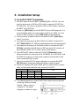
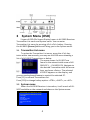
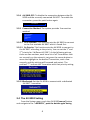
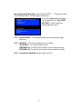
KV-901T & AV-901R
Quick Guide
This quick guide provides basic information only, for a
complete version of user’s manual please down load at:
http://www.avextender.com/comm/upfile/p_110913_
04468.pdf
Copyright© 2011 Beacon Extender Inc. All rights reserved.
Version 4.01
1. Introduction
The KV-901T/AV-901R is a solution of Audio/Video extension
over IP Ethernet LAN. The KV-901T is Transmitter (TX), the AV901R is Receiver (RX). The TX connects with PC or any source with
VGA/DVI/Audio output. The RX connects with display and speaker.
Any 100M, Giga or Fiber Ethernet LAN switch can be used to interconnect the TX and RX. They are flexible in one-to-one Unicast
mode, or in one-to-many/many-to-many Multicast mode.
1.1
Specification
Input video & resolution
Input video can be VGA or DVI-D in all standard resolutions from
640 x 480 to 1920 x 1200 @ 60Hz ~ 70Hz and the following special
resolutions 1440 x 900, 1400 x 1050, 1680 x 1050, 1360 x 768.
Output video & resolution
Output video can be VGA or DVI-F in all standard resolutions from
640 x 480 to 1920 x 1080 @ 60Hz ~ 70Hz and the following special
resolutions 1440 x 900, 1400 x 1050, 1680 x 1050, 1360 x 768.
Output frame rate
640X480@70fps, 800X600@70fps, 1024X768@60fps, 1280X1024
@30fps, 1600X1200@30fps, 720X480@60fps, 720X576@50fps,
1280X720@30fps, 1440x900@30fps, 1400x1050@30fps,
1680x1050@30fps, 1360x768@30fps, 1920X1080@25fps
Scalar support: Allows difference input and output resolution, also
support input-VGA/output DVI-D, input DVI-D/output VGA
LAN: 10/100Mbps, Auto-MDIX, Flow control.
IR Bridge: IR in/out, 38 KHz. (optional)
Remote PC Control: PS2 or USB (optional).
Audio/Microphone: 48 KHz stereo audio and microphone.
RS232 Bridge: AV-901R support remote RS232, baud 2400 ~
115200 (optional).
1
2. Installation Setup
2.1 Install KV-901T Transmitter
1. The DVI input of the KV-901T is [DVI-I] (VGA + DVI-D). You can
use the accessory of VGA-to-DVI cable to connect KV-901T to
PC VGA-Out. Or you can prepare a DVI-to-DVI cable to connect
KV-901T to PC DVI-Out.
2. There is a [VGA-Out] on the KV-901T for the VGA loop-out. It is
only available when the input video is DVI-A (or VGA). You can
attach a VGA monitor on this [VGA-Out] for local display.
3. Use accessory of audio cable to connect KV-901T [Line-IN] to
the PC Line-Out.
4. Use optional accessory of Mini USB-to-A cable to connect KV901T [Mini USB] to PC USB for keyboard/mouse remote control.
5. Use optional accessory of IR blaster cable to connect KV-901T
[IR Out] and adjust the IR blaster LED face to the IR receiver of
your Media Center PC, TV tuner card or DVD player.
6. Use CAT5e/6/7 cable to connect KV-901T [Ethernet] to the
Ethernet switch (or directly to the AV-901R). All of KV-901T and
AV-901R must be put in the same network and should not be
inter-connected with router.
7. Use the included 12V DC power adapter to connect KV-901T
[DC IN] power socket and plug the power supply to wall.
8. There is a [Status] LED and 2 RJ45 LEDs on the KV-901T, please
refer to the below table for the status of KV-901T:
[Status] LED
Red
Green
RJ45 LED
Green
On
Blink
Orange
On
On
On
On
On
On
Status
System OK, network is not connected
System failed
System OK, network is connected
System OK, network overload
9. The [Reset] button on the KV-901T Rear panel can be used for
entering Advance Setup
Mode , please refer to
Chapter 4. The panel
diagram is shown as right:
2
2.2 Install AV-901R Receiver
1. The DVI output of the AV-901R is [DVI-I] (VGA + DVI-D). You
can use the accessory of VGA-to-DVI cable to connect AV-901R
to the VGA monitor. Or you can prepare a DVI-to-DVI cable to
connect AV-901R to the DVI monitor.
2. Use accessory of audio cable to connect AV-901R [Line Out] to
speaker and plug microphone into the [Mic In] port.
3. If you need remote keyboard/mouse function, plug keyboard
and mouse to the [PS2] or optional [USB] port.
4. If you need remote RS232 function, plug RS232 cable to the
[RS232] port.
5. If you need remote IR function, connects optional IR receiver
cable to the [IR extender] port and positioned the receiver to
be visible from the front of the Display.
6. Use CAT5e/6/7 cable to connect AV-901R [Ethernet] to the
Ethernet switch (or directly to the KV-901T). All of KV-901T and
AV-901R must be put in the same network and should not be
inter-connected with router.
7. Connect the included DC 5V 2A power adapter to the DC-IN and
plug the power supply to wall. To avoid damage to the AV-901R,
please use power adapter in the package.
8. There is a [Source] button on the front panel for the system
OSD operation menu. Please refer to Chapter 3 for detail.
9. There is a [Power] LED and 2 RJ45 LEDs on the AV-901R, please
refer to the below table for the status of AV-901R:
[Power] LED
Red
Green
Off
On
Blink
On
On
Green
[RJ45]
Orange
Status
On
No Power
System OK, network is not connected
System failed
System OK, network is connected, but not able to link with Transmitter
On
On
System OK, linked with Transmitter
On
On
On
On
On
On
System OK, dis-connected with Transmitter (the [Power] LED in orange
color)
System OK, network overload
10. The [Reset] button on the AV-901R Rear panel can be used for
entering Advance Setup Mode , please refer to Chapter 4.
The AV-901R panel diagram is shown as below:
3
3 System Menu (OSD)
2 types of OSD (On Screen Display) menu in AV-901R Receiver:
Transmitter List menu and System menu. You can enter
Transmitter List menu by pressing <Ctrl><Ctrl> hotkey. Pressing
the AV-901R [Source] button will bring you to the System menu.
3.1
Transmitter List menu
To active the Transmitter List menu, press the <Ctrl> key
twice within two seconds, you may see the OSD menu showing a
list of all KV-901T Transmitters as below.
The menu shows 4 x KV-901T are
found in the network with name of KV9001-PC1, … KV-9001-PC4. Navigate to
the desired Transmitter with the arrow
keys, and press <Enter>. The selected
KV-901T appears on the display, and
you can use keyboard/mouse to control the selected PC.
Press [F1] to refresh Transmitters list.
Press [F10] to change hotkey option: <CTRL>, <SHIFT>, or <ALT>.
3.2
System menu
When the AV-901R Receiver is turned on, it will search all KV901T available on the network and show on the System menu:
>KV-901T-0337 (192.168.168.201, 03:27)
>KV-901T-0428 (192.168.168.202, 04:28)
>VGA SYNC
>REFRESH
>KV-901T SETTING
>AV-901R OFF
>Connection Method
>EXIT
4
Press the [Source] button to select KV-901T, after 3 seconds the
AV-901R will connect to that KV-901T as below:
Connecting to …
After the connection is established, the AV-901R will display the
screen that is connected to that KV-901T.
3.3
Other System menu Functions
When the [source] button of AV-901R is pressed, the system
menu OSD will pop out. You can press the [source] button to
navigate other System menu functions.
3.3.1 VGA SYNC: This function is only available when the KV901T is connected with VGA input, when the picture shifts
from screen, use this function to auto adjust the picture.
3.3.2 REFRESH: To refresh the KV-901T Transmitters list.
3.3.3 KV-901T SETTING: Use this function to setup KV-901T:
>MULTI/ONE AV-901R
>BANDWDITH SETTING
>INFORMATION
>EXIT
3.3.3.1 MULTI/ONE AV-901R: To set KV-901T in Multicast mode
(for one-to-many) or Unicast mode (for one-to-one).
3.3.3.2 BANDWIDTH SETTING: KV-901T has 3 levels of bandwidth:
LOW, MID, HIGH. Please note to set LOW, it will use lower
network bandwidth and get a more efficient performance
but will come with lower image quality.
3.3.3.3 INFORMATION: Show the KV-901T/AV-901R basic
information:
KV-901T
VERSION aa26
SUPPORT MULTI AV-901R
BANDWIDTH LOW
DVI IN 1024 X 768
AV-901R
VERSION a901 0126
IP 192.168.168.22
VGA OUT 1024 X 768
MIC IN
INTERNAL IR
5
3.3.4 AV-901R OFF: To disable the connection between the AV901R and the currently connected KV-901T. To enable the
connection, press the push button again.
AV-901R off
3.3.5 Connection Method: The system provides 3 connection
method:
>First Available
>By Priority
>Dedicated
>EXIT
3.3.5.1 First Available: This function sets the AV-901R to connect
to the first available KV-901T which it found first.
3.3.5.2 By Priority: This function sets the AV-901R to connect to
st
the KV-901T according to the priority. You can set the 1 and
nd
2 priority for 2 different KV-901T. As the following picture,
there are two sections, each has a list of all Transmitters that
are currently on the network; just press the source button to
move the highlight to the desired Transmitter, wait a few
seconds, and the settings will be saved and restart. The
prefixed * indicate the Transmitter with that priority setting.
3.3.5.3 Dedicated: Set the AV-901R to connect with a dedicated
KV-901T Transmitter.
3.4 The AV-901R Setting
From the System menu, push the AV-901R [source] button
and navigate to the >REFRE“H , push the button again during
6
the system is still showing Searching KV-901T … . The menu with
AV-901R SETTING will be shown as below:
Push the [source] button again
>KV-901T-0337 (192.168.168.201, 03:27)
>REFRESH
to navigate to the >AV-901R
>AV-901R SETTING
SETTING , it will show the
>AV-901R OFF
following OSD menu:
> AUDIO INPUT
> IR INPUT
> Connection Method
> RETURN
3.4.1 AUDIO INPUT: To enable/disable the microphone input
function.
3.4.2 IR INPUT: There are 3 options for IR input:
IR DISABLE: Turn off the IR function.
INTERNAL IR: To set the IR receiver from internal socket.
EXTERNAL IR: To set the IR receiver from extension cable.
3.4.3 Connection Method: Please refer to 3.3.5.
7