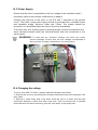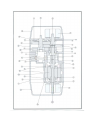
1
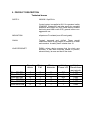
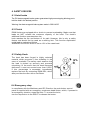
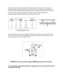
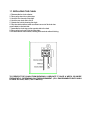
MACHINERY DIRECTIVE
This user's manual deals with all the electric and mechanical chain
hoists manufactured by the company
R.W.M. srl Via Colleoni 80/7 36034 Molina di Malo - VI
tel. 0445 / 637002 - fax. 0445/637019
rwmitalia.com - mail: [email protected]
Hoists are designed and manufactured in compliance with the
following directives:
98/37/CE
Machinery Directive
2006/95/CE
Low voltage Directive
89/336/CEE - 92/31/CEE
Electromagnetic compatibility Directive
UNI EN 12100 part 1 e 2
Machinery Safety
CEI EN 60204-1
Safety of the electric equipment
CEI EN 60204-32
Safety of the lifting electric equipment
CEI EN 13850
(Emergency stop device)
IEC-34-5
(IP Protection)
FEM 9511
(mechanism classification)
FEM9671
(chain quality, selection criteria)
FEM 9681
(choice of the shifting hoists)
FEM 9682
(choice of the lifting hoists)
BGV D8
(German safety standards)
Each hoist component complies with the mentioned Directives and EC
trademark, which states the integrity and conformity.
1. Manual's contents
2. Users
3. How to read the manual
4. Conditions of use
5. Product Description
6. Safety devices
7. How to work with the product
8. How to transport the product
9. Installation
10. How to use the hoist only
11. How to remove the hoist after use
12. Checking the hoist before start
13. Setting the hoist
14. Product's use
15. Product's use after a period of inactive state
16. Regular checks and maintainance
17. Maintainance and repair
18. Chain replacement
19. How to repair eventual product's failure
20. Label
21. Guarantee
1. MANUAL’S CONTENTS
This manual contains instructions for installation, use, and maintainance of theelectric chain
hoist and must always belong to a responsibleperson and be available for consultation.
Therefore it is compulsory to readthis manual before using the hoist. This manual complies
with all of the European Directive 89/392CEE and all relative and following amendments
about the user's dues according to European regulations on safety matters.
2. USERS
The current manual is written for:
- the person in charge of the set-up area
- the person and whole staff who work at the installation
- the operator
- the person who operates the maintainance.
The user must keep this manual in perfect state, in order to have it ready for
consultation. In case of loss, please immediately ask for a new document, by
contacting:
R.W.M. srl - Via Colleoni 80/7- 36034 Molina di Malo (VI)
tel. 0445 / 637002 - fax. 0445/637019
3. HOW TO READ THE MANUAL
When you find this symbol, read carefully!
Before using your RWM Hoist, you must read this manual.
The correct functioning of the hoist is tightly linked to the correct
compliance of the user with the instructions of this manual.
The instructions written in this manual fully comply with the Machinery
Directive and the EC Directive on safety.
4. CONDITIONS OF USE
The hoist must only be used to vertically lift loads and the stated SWL must not be
exceeded. Any damage occured to things or people due to improper use of the
product, will not be considered under RWM's responsibility..
4.1 Limitation of use
The hoist is not explosion proof and its use in an explosive atmosphere is not allowed.
4.2 Safety regulations
ALWAYS make sure you are correctly using the hoist.
The hoist must ONLY be used by trained and skilled operators.
Do not use the hoist to lift or transport people.
Do not lift the load near or over people in version DIVO D8.
It is allowed to rig and suspend static loads over people when using D8+ version of
the hoists.
Warn all people in the nearest area that you are running the hoist.
Do not exceed the maximum loading capacity written on the hoist label.
4.3 Instructions before use
Chain and bearing elements must always be checked before use.
Always check the hoist's break efficiency.
Always check the chain is well lubricated.
Always check the chain is not twisted.
Do not enlarge chain's length, it must be totally replaced when damaged.
Do not modify the bearing elements.
4.4 Instructions for use
Do not allow the load to swing
Make sure the load is safely tightened to the hook
Always concentrate when using the hoist
Make sure the load does not crash against any other fixed object
When lifting a load the chain’s tension must always be vertical to the hoist
Avoid continuous ON – OFF switching of the control buttons
Never suspend the load over the extreme point of the hook
Do not use the clutch continuously at its limit, as it will cause excessive wear,
leading to an eventual and premature failure of the hoists components.
Do not use the pendant cable to pull the hoist into position.
4.5 After Use
NEVER leave a load suspended or unattended.
ALWAYS set the emergency STOP button.
Turn the power supply off.
NEVER make repairs without observing the current instructions.
4.6 Maintainance
Regularly lubricate the lifting chain.
5. PRODUCT DESCRIPTION
Technical issues
SUPPLY:
230/400 V 3ph 50 Hz.
Control system is supplied at 24 V for operators’ safety
(EN60204) Waterproof and drip proof for complete
protection and longer life (IP65 DOM 40050).Pendant
and hoist panel.Hoist motor IP55, general in-door nonaggressive use.
INSULATION:
all parts are F insulated (max 95°cen tigrade).
CHAIN:
Treated, tempered and nitrified. These special
treatments ensure a high degree of resistance to wear
and corrosion. Its safety factor is better than 10.
LOAD SPROCKET:
RWM’s unique design ensures that the chain runs
smoothly. It has been thermally treated to prevent,
almost entirely, its wear and that of the chain.
Divo 250 D8
Divo 250 D8+
Divo 500 D8
Divo 500 D8+
Divo 1000 D8
Divo 2000 D8
Speed
m/min
Chain
Fall
Chain
diameter
Hoist
Power kW
4
4
4
4
4
2
1
1
1
1
1
2
5
5
5
7
7
7
0,8
1
0,8
1
1
1
Hoists
Revolutions
per minute
1400
1400
1400
1400
1400
1400
6. SAFETY DEVICES
6.1 Hoist brake
The DC electromagnetic brake system guarantees high power stopping allowing you to
hold the load in the desired position.
Warning: the electromagnetic brake system works in 220 Volt DC
6.2 Clutch
RWM Hoists are equipped with a clutch to prevent overloading. Make sure that
loads do NOT exceed the maximum capacity of the hoist. The clutch's
additional function operates when the
hook reaches the top and bottom of its path. However, this is only a safety
feature and should not be used as a working limit. This function exploitation
could lead to mechanical failure.
WARNING: the hoist's clutch is set to 15% of the rated load.
6.3 Safety Hook
The hook has been forged in highly resistant
material which prevents it from breaking in the
event of overload. The safety catch ensures that
the load is picked up securely and prevents
unhooking. In the event that the hook becomes
deformed, it must not exceed more than 0.25%.
If this percentage is exceeded, immediately
replace the hook by contacting RWM SRL, which
also provides the user with a certificate.
6.4 Emergency stop
In compliance with the Machinery and EC Directive, the push button control
panel is supplied with an emergency mushroom head button, which, if pressed in
an emergency situation, stops the hoist. To re-start the hoist,
turn the stop button to the RIGHT to release the button.
7. HOW TO WORK WITH THE PRODUCT
One person only must run the hoist.
The controller (panel or pushbutton) is the working
position lavoro.
8. HOW TO TRANSPORT THE PRODUCT
The hoist is stored in a proper container. The container, considering its dimensions, can be
manually moved. However, we advise you to use proper machines.
The hoist is also equipped with two handles for a comfortable move.
9. INSTALLATION
Prior to installing the hoist, ALWAYS ensure that the structure it is being
suspended from is capable of carrying the hoist AND its load, and has been
certified to do so.
Also make sure that the power supply being used complies with that
specified for the hoist..
10. HOW TO USE THE HOIST ONLY
10.1 Assembling the chainbag
1) Place the chain bag in such a way that the hole corresponds with that of the
hoist body.
2) Insert the chain.
3) To avoid chain twisting, NEVER insert all the chain at once.
4) Insert the screws and secure them with the relative nut to the hole placed at
the edge of the central body.
10.2 Lubricating the chain
Use simple industrial oil in order to prevent chain or load wheel's failure or damage.
10.3 Power Supply
Ensure that the hoist is compatible to the line voltage of the installation and if
necessary perform the relevant modifications to adapt it.
Connect the feed line to the hoist, to the R,S and T terminals of the printed
circuit. The hoists’ power feed supply should be provided from a suitable fused
and isolatable supply. Minimum cable size 1.5mm. The isolator should be
mounted in an accessible place as close to the hoist as possible.
The fourth wire, with a yellow-green insulating sheath, must be connected to the
earth terminal situated inside the electrical board and then connected to the
earth system.
WARNING: If used with an incorrect voltage, the hoist can suffer
serious damage. Ensure that the line voltage corresponds to
that required (voltage indicated on the hoist plate).
10.4 Changing the voltage
To move from 400 V to 230 V, please read the following instructions:
1. Remove the cover by unscrewing the socket head screws and removing them from
their seats.
2. Remove 3 white wires and 3 red wires. With the use of a tester find the right
connection between a white wire and a red ones. Then re-connect the 2 coloured
wires that does not have continuity (one red, one white) in the proper site.
12. OPERATIONAL TEST
12.1 Lifting test
Switch on the power to the hoist with the isolator and then turn the emergency stop
button in order to release it.
Press the button
or
on the pendant to check
the direction of the hoist. The movement of the chain should correspond with what
is indicated on the pendant button.
If the direction is reversed, disconnect the isolator and reverse the two wires on
terminals S and T.
If the hook does not move, check the power supply - is there power to the hoist? / Is
there a phase down?
12.2 Clutch test
Keep the button
body where it stops.
on the pendant pressed to make the hook climb to the hoist
Repeat the same manoeuvre pressing the button
to lower the hook until the
chain stop comes up against the hoist body. In both cases check that the hoist motor
continues to run and the clutch slips, if it does not, call RWM, or an authorised retailer.
12.3 Brake test
with a small load of 20kg operate the
and
several times to check the
correct operation of the hoist and brake. When either button is released the hoist
should stop and the load held without slipping.
Repeat the above with the SWL of the hoist, again the load should be held without
slipping.
12.4 Operating test of the emergency stop button
Press one of the buttons and then the emergency stop button
to check that the
hoist stops and remains stopped until it is released. Repeat with the other button. If this is
not the case check the control connections.
13. OPERATION
13.1 Design of the hoist
he hoist is designed to lift vertically and to carry loads in a horizontal path. These
loads have to be within the maximum capacity specified on the hoist and certificate.
ANY improper use or a use that does NOT conform to the operating specifications
relieves RWM of any responsibility.
13.2 Safety in the work environment
- The operator must have a clear view of the load at all times to operate the
hoist.
- The hoist must only be used for the purpose it has been intended for i.e. the
lifting and moving of loads.
- The loads which have to be moved must have a weight equal to or lower than
the maximum capacity of the hoist, this is marked on the hoist and on the test
certificate.
- You MUST switch off the hoist when not in use.
- When the work is finished, the emergency stop button must be pressed in
order to stop the electric feed until work starts again.
- Before carrying out any maintenance operations, tests etc. you MUST
ensure that the electrical supply is disconnected.
- No operation / repairs or maintenance should be made when the hoist is
moving.
- You should not use the machine with an electrical cable or a plug, which is
damaged or in bad condition.
- The isolator must be easily accessible to the operator.
- The electrical panel of the machine can not be changed and has to be
connected with the appropriate electric voltage.
- The structure of the hoist can not be modified.
- ANY improper use or any use that does not conform to the specifications as
above, releases RWM of any responsibility.
14. INSTALLING THE HOIST AFTER A PERIOD OF INACTIVITY
After a period of inactivity (6-12 months) it is recommended that you check the motor
functions correctly before installing the hoist. It is possible that the brake disk may be
stuck due to the process of oxidation and warping of the brake lining, especially if the
machine has been left in a damp atmosphere or where steam is present. In this
case, to ensure that the motor functions correctly, simply remove the cover, remove
the coils and clean the brake.
15. MAINTENANCE AND PERIODICAL CHECKS
15.1 Daily checks
1. Ensure that the brake is functioning correctly.
2. Ensure that the clutch is functioning correctly, both up and down.
3. Ensure on the pendant, that the emergency stop button operates correctly.
4. Ensure that all the components are properly secured.
5. Ensure that the chain is well lubricated.
6. Ensure that the trolley runs evenly on the beams.
7. Ensure that the limit switch is working efficiently.
8. Ensure that the trolley brake functions correctly.
15.2 Monthly checks
1. All checks as daily checks
2. Ensure that the pins of the hoist carrying the trolley are not bent or loose.
3. Inspect the trolley plates to ensure that they are not out of shape.
4. Measure the pitch of the chain and ensure that the dimensions do not exceed
those featured in the following table. If the dimensions do exceed the allowable the
chain should be replaced by a competent person, paying particular attention to the fit
of the new chain on the load sprocket. Using a gauge, carefully check the
measurements indicated below by measuring 5 chain links.
5. Ensure that the hook is not deformed. Measure the size of the hook and check
that it is not worn. Otherwise replace. Permanent deformation measured from the
hook opening must never exceed 0.25%.
WARNING: Only assemble original RWM spare parts on the hoist.
It is a statutory requirement that a competent person inspects the hoist
at regular intervals.
16. MAINTENANCE
16.1 Adjustment of the clutch
1. Isolate the hoist.
2. Remove the cap (unscrewing it from its seat) keeping attention to the counterbalance weight inside.
3. Loosen the nut to adjust the tension of the spring-cup.
4. Connect the hoist, lift the SWL of the hoist, adjust the clutch until the hoist lifts the load. Repeat with the
SWL plus 25% and set the clutch until it just starts to slip.
5. Isolate the hoist.
6. Replace the end cap and screws.
16.2 Replacing the clutch or the spring cup
1. Isolate the hoist.
2. Remove the cap (unscrewing it from its seat) keeping attention to the
counterbalance weight inside.
3. Completely unscrew nut 7
4. Draw out the thrust-plate 6
5. Draw out the spring-cup 4-5
6. Draw out the lining-plate 3
7. Clean flat the seat
8. Assemble the new lining-plate
9. Finish assembling, putting in order: spring-cup, thrust-plate and the nut.
10. Adjust the clutch as 16.1
11. Replace the end cap and screws.
16.3 ADJUSTMENT OF THE BRAKE
I paranchi DIVO sono equipaggiati con doppio freno di tipo AC2 400VAC per il DIVO 500 e
AC4 400VAC per il DIVO 1000.
Prima di qualsiasi operazione assicurarsi che l’alimentazione elettrica sia disinserita,
altrimenti provvedere a staccare l’alimentazione al paranco.
1)
2)
3)
4)
Isolate the hoist.
Remove the end cap.
Loosen the adjusting screw to adjust the tension of the springs.
Connect the hoist, lift the SWL and check the brake. Repeat stage 1,3, and 4
until the brake does not slip with the load lifted. (maximum load is indicated in
the certificates enclosed with the hoist.)
5) Isolate the hoist
6) Replace the end cap and screws.
!ATTENTION!: The braking flange must have from 0,02 mm of air gap
from the coil.
16.4 Replacing the brake or the springs
1. Isolate the hoist.
2. Take off the cap (completely unscrewing the screws) and take the cap off its seat.
3. Completely unscrew the screw plug and take off the springs.
4. Draw out the screws and take off the magneto.
5. Draw out the lining-plate.
6. Clean the flat-seats.
7. Assemble the new lining-plate.
8. Finish assembling putting in order: magneto, screws, springs and the plug.
9. Adjust the brake.
10. Replace the cap and close the screws.
17. REPLACING THE CHAIN
1. Disassemble the chain collector.
2. Remove the aluminium chain strap.
3. Hook link B to the end of the chain.
4. Hook the new chain link to link B.
5. Operate the hoist by lowering the chain.
6. Stop the chain’s descent when a sufficient amount of the chain has
accumulated on the load side.
7. Assemble the chain stop on the opposite side to the load.
8. Remove the hook and fit it to the new chain.
9. Re-assemble the chain collector, inserting the linear chain without it kinking.
TO PREVENT THE CHAIN FROM WEARING, LUBRICATE IT ONCE A WEEK, OR MORE
FREQUENTLY, DEPENDING ON ITS ENVIRONMENT. (E.G. ENVIRONMENTS WITH HIGH
LEVELS OF ACID, DUST, SALT WATER).
18. TROUBLESHOOTING
THE HOIST DOESN’T MOVE
1
A phase is missing; connect the wires in the box correctly and ensure that the
current is correct.
2
A fuse is burnt out; replace.
3
The brake is blocked; disassemble it and clean it thoroughly (this can occur after a 6/12 month period
inactivity due to oxidation of the brake lining).
THE LOAD DROPS
The brake motor is worn out; check and repair the motor.
THE HOIST DOES NOT LIFT THE LOAD
Adjust the clutch.
THE HOIST DOES NOT STOP
The pendant control switch is stuck; replace.
CURRENT IS PRESENT ON THE HOOK
The system is not insulated; inspect the system thoroughly and ensure that the
system’s earthing is correct.
THE CHAIN MAKES AN ABNORMAL NOISE
1
2
The chain is dry: lubricate.
The load sprocket is worn out; replace.
THE TROLLEY DOES NOT RUN ON THE BEAMS
1
2
The beam is tilted; check and correct the tilt.
The beam is dirty with oil; clean the trolley beam with a cloth.
!WARNING!: FOR ALL REPAIRS, RE-ASSEMBLE ONLY ORIGINAL SPARE
PARTS.
21. GUARANTEE
All our equipment has undergone vigorous tests and is covered by a 12-month
guarantee valid from the purchase date. RWM undertakes to repair or replace free
of charge those parts that it deems defective within the guarantee period. The
guarantee does not cover replacement of the entire equipment. The guarantee shall
only be valid if the equipment has been purchased from an authorised distributor,
and if it has been used in accordance with the information given in the Instructions
Manual and on the warning signs. The guarantee shall not cover: accidental
damage due to transportation, the incorrect or negligent use of the equipment or
should the equipment be connected to voltages other than those recommended.
Any defective part that is replaced shall become the property of RWM. The
guarantee shall not be valid if the product is repaired or tampered with by any
unauthorised third parties. The guarantee for all RWM products is valid for 12
months from the purchase date.
MAINTENANCE AND REPAIR
Date
operation
outcome
signature
note
MAINTENANCE AND REPAIR
Date
operation
outcome
signature
note