1
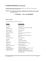
Analogue Addressable
Fire Control Panel
for
Apollo XP95 & Discovery Protocol
V4.1 and above
Operating Manual
MVEC -02 Issue 3.0 July 2008
NOTE
PLEASE READ THIS MANUAL BEFORE
HANDLING THE EQUIPMENT AND OBSERVE
ALL ADVICE GIVEN IN IT.
THIS PARTICULARLY APPLIES TO THE
PRECAUTIONS NECESSARY TO AVOID E.S.D.
Vector Operating Manual.
2
CONTENTS.
Introduction………………………………………………………………………………………. 4
Product Overview……………………………………………………………………………….5
Glossary……………………………………………………………………………………...……..6
Control Panel……...………..……………………………………………………..……………..8
Panel Indicators…………………………………...……………………………..…………….10
Keypad…………………………………….…...…………………….…………………………….11
LCD Display…………………………………………...……...…………………………………12
Menu and Control Functions………...…………………………………….….………...13
Function Buttons……………………………………………………………………...……..13
Access Levels…………………………………………………………………………...….14
Menu Flow Chart………………….……………………………………………………..….16
Key to Menu………………………….…………………………………………………..….17
Disablement Flow Chart…………....………………………………………………….....18
Engineering Options ………………..……………………………………………………...19
System Operation……………………………...………..……………………………….......20
Fire Alarm……………………………………………………………………………….......20
Silencing the Alarm……………….…………………………………...……………….…..21
Resetting the System…………….…………………………………………………….…..21
Evacuate………………………….…………………………………………………….…...22
Panel Buzzer…………………….……………………………………………………….…22
Fault Conditions………………….…………………………………….…………………...23
Fault Messages………………….………...………………………….…………………....24
Action after a Fire……………….…………………………………….…...…………….…25
Action after a False alarm………….……………………………...……….…………...…26
Action following a Fault………………………………………...………….……………....26
Avoiding false Alarms…………....…….………………….………………..……………...27
Vector Operating Manual.
3
INTRODUCTION
The Vector is a multi loop, analogue/addressable fire alarm control panel equipped with up to 64
zones. It has been designed In accordance with European standards EN54-2 and EN54-4 Fire
Detection and Alarm systems—Control and Indicating Equipment.
It utilises the latest surface mount technology with a flash programmable 16 bit Micro-controller for
easier software updates
It operates with the Apollo XP95 & Discovery protocol and supports the Apollo range of field devices.
Two internal sounder circuits are provided per loop and additional sounder circuits can be connected
to loop wired modules.
The control panel is programmable via the keypad controls or via a PC, allowing the configuration to
be created off-site and downloaded.
In addition to the requirements of EN54-2 the control panel has the following facilities:Test Condition, to allow the automatic resetting of zones in alarm for testing purposes. EN54-2
Section 10 option with requirements.
Fire Alarm Devices, to enable an audible warning to be sounded throughout a premises upon the
detection of a fire condition or the operation of a manual call point. EN54-2 Section 7.8 option with
requirements.
In addition to the requirements of EN54-2, all control panels have voltage free relay contacts for fire
and local fire which operate upon fire condition. These are to be used for local control and signalling.
The Vector has individually isolatable panel contacts via the menu with an Auto enablement feature
and the option to remove all disablements. The menu is comprehensive, yet easy to use, allowing
electrical isolation of the loop via the keyboard. The menu includes an enhanced test mode, with or
without sounders allowing all zones to be tested simultaneously if required.
It has a real time clock, with back up, utilising a smart cap rather than a battery, thus eliminating
battery life issues.
The Vector incorporates a very fast auto learn sequence only learning selected parts of the loop, and
if required can unlearn devices from the system.
It supports the new Apollo ancillary base sounders and relays, local, zonal or common operation.
A device monitoring mode allows activation of the device outputs and control of the loop polling
direction. Also there is a selectable maintenance scanning threshold.
The Vector has genuine peer to peer 16 panel networking, utilising reliable CAN bus technology, with
response settings to evacuate,1st alarm, 2nd alarm, precinct and fault signals, with programmable
responses for loop sounders, panel sounder circuits, remote relays and loop modules.
This User's manual is supplied with the control panel which in addition to explaining the operation of
the panel, incorporates a log book and details of the user's responsibilities for testing and maintaining
the system. It is intended that the user's manual forms part of the documentation package passed to
the customer on completion.
Vector Operating Manual.
4
PRODUCT OVERVIEW
The control panel is a 1 - 4 loop, 64 zone analogue/addressable unit with integral power supply and
space for a standby battery. It has two sounder circuits per loop, auxiliary volt free contacts and
various remote inputs and outputs.
The control panel comprises a sheet steel enclosure suitable for wall mounting with a hinged,
lockable front access door. It can be semi-recessed if required by using a suitable flushing bezel.
Cable entry is via the top or rear of the cabinet. 20mm 'knockouts' are provided in the top and in the
rear.
A separate key fits the door lock and the 'control enable' key switch. A 2 x 40 character, backlit LCD
is fitted to display event information and function and configuration menus. Alarm and status
information is provided by LED indicators and there is a 12 button keypad which controls the system
and allows access to the function and configuration options.
The control panel operates with the Apollo protocol and supports the XP95 & Discovery detection
devices. The full range of detectors, sounder controllers, I/O modules, conventional zone monitors,
etc can be incorporated into the system. In addition to the 64 fire zones, there are three further
options Alarms, Contacts and Inputs, which have special functions enabling auxiliary devices to be
configured for alternative operation, also four groups are provided for cause and effects configuration.
It is possible to power the panel from a remote power supply if required and input terminals are
provided to facilitate the remote supply input and also to monitor the unit for mains and battery
failure.
Access to the panel functions and configuration options is at different levels enabling restricted
access to certain functions. At the user level it is possible to disable parts of the system, set the time
and date, put the system into walktest mode and view the system status. Advanced options include
configuration, maintenance checks and fault finding mode.
The control panel incorporates an 'auto-learn' feature which enables the system devices to be
recognised on initial power up. Configuration of the system operation can be achieved via the panel
controls or by downloading data created in a PC software program.
Vector Operating Manual.
5
GLOSSARY
Address
An address is the unique identification applied to each field device in an addressable system
Addressable system
An addressable system is one where each field device has an address which can be identified and
displayed in an abnormal condition or for normal monitoring purposes. The address is normally
accompanied by a user-defined text message describing the device location, e.g. 'First floor corridor'.
Addressable devices are usually wired in a loop configuration.
Analogue/addressable system
In addition to device addressability, the detectors employed are analogue devices transmitting data
to the control panel which is then analysed and processed so that the appropriate condition can be
displayed. Analogue systems can provide greater immunity to false alarms and give advance
information about impending fire conditions.
Automatic system
An automatic system is one which includes detectors of some description, as opposed to one fitted
with manual call points only.
Device
A component of an addressable system connected to the loop circuit. It can be an input device such
as a detector or call point, or an output device such as a relay or sounder controller. Devices in an
addressable system are uniquely numbered and there is a finite number which can be connected to a
single loop.
Detector
A device which detects either flame, smoke or heat. Analogue detectors are often referred to as
sensors because of their ability to transmit variable data to the control panel.
Disabled
The condition of the system when part or parts of it have been isolated for any reason. It is possible
to disable individual addresses, complete zones and/or remote outputs. The normal condition is
'enabled'.
Field device
See Device
Fire procedure
A written procedure describing the actions to be taken in the event of a fire alarm. Procedures should
also include the actions required after a fire and in a fault condition. All staff should be conversant
with the fire procedures.
Input/output (I/O) device
A device which either monitors a remote function or provides a signal to control a remote function, or
both. Used with analogue/addressable systems to interface with other services. Each I/O unit has an
address.
Loop
The method of wiring an addressable or analogue/addressable system whereby the circuit
connecting the devices is wired from the panel and is returned to the panel to form a loop. With this
method a break in the loop circuit, although indicated as a fault, does not disable the operation of any
devices.
Vector Operating Manual.
6
GLOSSARY(Continued)
Manual call point (MCP)
Also known as a break glass unit, initiates a fire alarm condition when activated. MCPs comprise a
standard call point assembly fitted with an input module on analogue/addressable systems, and have
a unique address.
Sensor
See Detector
Short circuit isolator (SCI)
A device connected to the loop circuit which limits the loss of devices in a short circuit condition.
They are generally fitted between each zone to restrict the loss of detection to one zone in
accordance with BS 5839 Part 1. SCIs do not have an address and do not limit the number of
devices on a loop.
Sounder
A device which provides an audible warning of a fire alarm condition. Sounders may be bells but are
often electronic devices with a range of sound options and volume control. In most systems the
sounders must achieve a minimum level of audibility throughout the protected premises.
System type
Systems complying with BS 5839 Part 1 are classifed depending on the application. There are two
main categories, i.e. Life Protection (L type) and Property Protection (P type). Each category is subdivided depending on the level of protection required for the particular risk.
Zone
A zone is the sub-division of a building separated by fire resisting walls to form a compartment. When
applied to a fire alarm control panel it refers to the number of fire indicators available to identify the
location of a fire within a building. Each fire compartment generally comprises one or more zones.
Each floor of a multi-storey building is a separate zone, and each vertical structure (staircase,
liftshaft, etc.) is a separate zone. Smaller zones may be required in areas of high risk. In an
analogue/addressable system the zonal indicator denotes the general area of the fire whilst the LCD
indicates the actual activated device.
Vector Operating Manual.
7
CONTROL PANEL
Panel Controls
Logo
Badge
CONTROLS
OFF
EVACUATE ALARM
ON
ACTIVE
CONTROLS
SILENCE
RESOUND ALARMS
RESET SYSTEM
MUTE BUZ ZER
Key switch - Activate Controls
This Key switch is normally in the OFF position with the key withdrawn and stored where it can be
accessed by authorised personnel in the event of an alarm or fault. In the OFF position none of the
functions are operable, even though the system is completely operational. with the exception of the
“mute buzzer” key, scroll [2] [8] and [5] if an alarm should be present. This is to enable viewing of the
event text if no key is available.
If the keyswitch is turned to the ON position then the keypad becomes fully functional.
NOTE : It is not possible to withdraw the key in the ON position.
Key lock
This allows authorised engineering personnel access to the inside of the control unit.
WARNING : The power to the alarm unit should be isolated before gaining access. The voltages in
this unit are high enough to cause severe injury.
Vector Operating Manual.
8
CONTROL PANEL (Continued)
General description
The control panel comprises a sheet-steel wall mounted enclosure with a lockable hinged door. All
the user controls and indicators are mounted on the fascia of the unit - there are no user controls
within the panel.
Normal Operation
In the normal operating mode only the green Supply Healthy LED (light emitting diode) should be
illuminated. The LCD (liquid crystal display) should be showing the current time, date and company
name, if programmed.
Fire Alarm Event
A fire alarm event is caused by the activation of a field device. It may be generated automatically by
a smoke or heat detector sensing smoke or heat, or manually by the operation of a call point. In
either case it will cause an audible alarm to be given (usually throughout the building) and the event
details to be displayed and indicated on the control panel.
NOTE . Each system is individually configured for the required operation. Space is provided in the
manual to record the method of operation of this system, which should be completed by the installer.
The prescribed emergency fire alarm drill should commence immediately the alarm is heard (see
System Operation)
Fault Event
A fault event is generated when the control panel detects an internal malfunction or a fault on an
external circuit or device. A fault is indicated by the relevant LED/s and the buzzer sounding. A fault
description is shown on the LCD.
Control Event
A control event is caused by the operation of one or more of the keyboard pushbuttons. All controls
are inoperable until the 'Controls' keyswitch is set to the 'on' position, to prevent unauthorised
operation. A keypad is provided to silence and reset the system following a fire or fault event, initiate
an evacuation alarm, and to access the menu functions.
Vector Operating Manual.
9
PANEL INDICATORS
FIREFIREFIRE
FIRE
TEST MODE
ACTIVE
DISABLEMENTS
ACTIVE
SUPPLY
HEALTHY
COMMON
COMMON FAULT
FAULT
FIRE
ALARM
SYSTEM ALARM REMOTE REMOTE
FAULT
FAULT ACTIVE DISABLED
ARW
MORE
PSU
Fire
Indicates the presence of a Fire Alarm signal or an Evacuate command.
Test Mode Active
Indicates system is in the Engineers Test mode, with limited operational capabilities.
Disablement Active
Indicates that part of the system is disabled (isolated)
Supply Healthy
Indicates that the Mains or Battery supply is present.
Common Fault
Indicates that a fault is present on the system. The LCD will show the details.
Pre-Alarm
Indicates that a detector has recorded a higher than normal analogue value which could signal an
impending fire condition.
System Fault
Indicates that the processor has halted. This can only be reset by an engineer.
Alarm Fault
Indicates a fault on the alarm circuit.
Remote Active
Indicates that the Remote output relay has been activated.
Remote Disabled
Indicates that the Remote output relay has been isolated for maintenance or testing.
ARW
Auto Reset Warning. Indicates processor has automatically re-started. Must be reset by “Reset
System” Key 9 on keypad.
More
Indicates that there are more events
PSU
Indicates power supply failure. The LCD will show the details.
Fire Detection Zones
Sixteen indicators (Zones 1-16) to show which area (group of devices) has activated in a fire
condition.
Vector Operating Manual.
10
KEYPAD
Vector Operating Manual.
11
LCD DISPLAY
The LCD displays event information, status information, and the option menus. It has two lines of
text, each with 40 characters , and is backlit when there is an active event on the system or the
menu options are accessed. In the normal operating mode the backlight is off and the top line
displays a default text message or user-defined text. The second line displays the current time
and date, e.g.
VECTOR MULTILOOP
SYSTEM NORMAL
9:36 15/03/04
When an event occurs, the backlight is activated and the LCD shows the event details, e.g.
FIRE
PANEL 01
Z0NE 001
CARETAKERS OFFICE
1 OF 1
The display shows the event type, i.e. Fire, the zone that the activated device is in, i.e. zone 3, the
device location text and the number of events, i.e. 1.
Pressing button [5] reveals the device information, Type, i.e manual call point, address number
and time and date of the event. This button will function regardless of status of keyswitch.
NOTE : Fault conditions on the system are suppressed when Fire events are present. The
SYSTEM FAULT LED is illuminated and faults can be viewed if required via the 'View Active
Faults' option - when button [5] is pressed.
NOTE:- Keyswitch must be on to view active faults with button [5]
The bottom line displays a text message describing the device location.
In the engineering mode, menu options are displayed as follows:
SELECT MENU OPTION
5 — SET CLOCK
The Keypad is used to navigate through the menu options and select functions as described in
the installation and commissioning manual.
Vector Operating Manual.
12
MENU AND CONTROL FUNCTIONS
General
The control panel incorporates facilities to alter the status of the system, e.g:- it is possible to isolate
parts of the system if there is work in progress, or a particular device is faulty and causing unwanted
alarms. The system can be put into test mode to allow an engineer to activate devices without
causing a general alarm, and the time and date can be changed, e.g. for British Summer Time.
These functions are accessible to the user at access level 2 but care should be exercised when
utilising the functions as it is possible to disable some or all of the system. It is recommended that
before attempting to enter the options menu the features are fully understood, and the operator is
familiar with the controls used to navigate the menus and select options.
Function buttons
Four of the keypad buttons are used as function buttons when the options menu is invoked.
Most of the panel functions, including configuration, are controlled by these buttons which have the
following functions:[MENU]
The Menu button is used to initially invoke the options menu. Press once to enter the Menu , and
press again to Exit.
[2] and [8]
The 2 and 8 buttons are used to move to and then select the Menu options. Once an option has been
selected, the Menu button should be pushed again to exit.
[5]
The 5 button on the keypad is pressed when the option selected needs to be viewed, or to view the
text or an active event.
[4] and [6]
The 4 and 6 buttons are used to position the cursor along a full display line in order to adjust various
options available.
Vector Operating Manual.
13
MENU AND CONTROL FUNCTIONS (Continued)
Access levels
To prevent unauthorised operation of the panel controls and functions, access is restricted in
accordance with the requirements of EN54 -2.
The following access levels apply:Level 1
Full restrictions.The internal buzzer MUTE only is available at this level and Scroll and
Select if ‘Fire’ is active.
Level 2
CONTROL keyswitch ON. The control switches are operable and limited menu
fuctions available.
Level 3
An access code must be entered to gain access to the configuration and advanced
options. An additional access code must be entered in order to set the
Disablements and to activate the Test Mode.
Level 4
Configuration software. Download facilities are available for off-site
programming.
NOTE :Amending the system configuration can have serious effects on the operation of the
equipment and should only be undertaken by a competent person who has information concerning
the devices installed and the specified operational requirements.
The system should be fully tested after any alterations to the configuration
program.
Level 2 Options Menu.
1.
2.
3.
4.
5.
6.
7.
View active faults.
View active disablements.
View/Clear event Logs.
Set disablements.
Set Clock.
Activate test mode.
Engineering options.
Vector Operating Manual.
14
MENU AND CONTROL FUNCTIONS (Continued)
Menu Procedures.
The following procedures are common to all of the menu options and should be understood before
attempting to alter the system status.
To access the Options Menu the CONTROLS key switch must be in the ON position.
Press the [MENU] button on the KEYPAD to display the following :-
* SELECT MENU OPTION *
1. VIEW ACTIVE FAULTS
Use the [2] and [8] keypad buttons to toggle (scroll) to the required option, then press [5] to display
the required information.
At any time, pressing [MENU] again will return you to the menu options, or in some cases return you
to the last step.
Depending on the option selected, there will be sub-menu items which can be accessed by the [5]
key or scrolled across to, using the [4] and [6] keypad buttons.
When satisfied with the data obtained, press [MENU] to return to the initial screen.
Vector Operating Manual.
15
MENU AND CONTROL FUNCTIONS (Continued)
Menu flow chart.
(TOGGLE 2 & 8)
YES
NO
MENU
1
EXIT
KEY 5 TO VIEW
VIEW ACTIVE FAULTS
FAULTS
VIEW / CLEAR EVENT
LOGS
3
4
5
SELECT
LOOP
VIEW ACTIVE
DISABLEMENTS
2
SET
DISABLEMENTS
SET CLOCK
5
5
5
ENTER
MANAGER
CODE
2/8
PAGE
18
ENTER TIME & DATE
KEY 5 TO VIEW
DISABLEMENTS
1
VIEW
ALARM LOG
2
VIEW
FAULT LOG
3
VIEW
USER LOG
CLEAR
LOGS
4
USING KEYPAD
6
ACTIVATE
TEST
MODE
5
ENTER
MANAGER
CODE
SELECT ZONE IN
TEST
(2/8 scroll)
SOUNDER
6
ON/OFF(2/8)
OR ZONAL
0 - ALL ZONES
1
1
print alarm log
2
print fault log
3
print user log
4
print
parameters
80
7
8
PRINT OPTIONS
ENGINEERING
OPTIONS
Vector Operating Manual.
5
PLEASE
REFER TO
ENGINEERS
MANUAL
2/8
16
MENU AND CONTROL FUNCTIONS (Continued)
Key to menu.
1.
View active faults.
This option provides a method of viewing faults on the system when there are active fire
events present.
2.
View active disablements.
This option allows the user to identify parts of the system that have been isolated.
3.
View / Clear event logs.
This option allows the Alarm log and the Event log to be inspected and if required can be
cleared
4.
Set disablements.
This option allows remote outputs, sounders, loop and zones to be disabled and also enabled
manually or automatically at a preset time and date. An optional managers code can be used
to allow access to this function.
5.
Set clock.
Allows the time and date to be entered via the keypad.
6.
Activate test mode.
Allows zones to be tested individually or all together. With or without sounder. An optional
managers code can be used to allow access to this function.
7.
Engineering options.
This option requires a security code to be entered before allowing entry.
•
Allows the system to automatically “ learn” new devices..
•
To connect to a PC
•
To set panel parameters.
•
To set system parameters.
•
To monitor individually the device response, change loop poll direction and activate the device
outputs.
•
To perform a maintenance check, set a threshold and list all devices within this threshold.
•
To check a loop corruption counter.
•
To set a Management access code to restrict access to the ’Set Disablements’ option and the
’Activate Test Mode’ facility.
Vector Operating Manual.
17
MENU AND CONTROL FUNCTIONS (Continued)
Set Disablements
MENU
SET DISABLEMENTS
4
5
ENTER
MANAGER
CODE
1
5
SET REMOTE
CONTACTS
DISABLEMENTS
TOGGLE
2/8
1
REMOTE SIGNAL
2
COMMON FIRE
TOGGLE
5
EN/DIS
SET SOUNDERS
DISABLEMENT
2
5
3
5
SET LOOP
ISOLATE
4
5
SET ZONES
DISABLEMENT
5
5
SET LOOP
DEVICES
DISABLEMENT
6
5
SET AUTO
ENABLE
TIMERS
TOGGLE 5
(ISO/DEISO)
3
COMMON FAULT
4
LOOP MODULES
TOGGLE 5
(ISO/NORMAL)
SELECT
LOOP No 1-4
(scroll 2/8)
SELECT ZONE
1- 80
SELECT
LOOP No 1-4
1
REMOVE ALL
DISABLEMENTS
TOGGLE
EN/DIS
5
5
DEVICES
2/8
OUTPUTS
TOGGLE
2/8
5
A 001 - A126
(2/8 scroll)
5
EDIT
TIME & DATE
2
7
TOGGLE
EN/DIS
SET AUTOENABLE TIME
ON/OFF(2/8)
TO CONFIRM
MENU
TO ESC
Vector Operating Manual.
18
MENU AND CONTROL FUNCTIONS (Continued)
Set Disablements.
1.
Remote Contacts can be disabled or enabled for test purposes. This applies to the signal
relay, the common fire, common fault or the loop module relays.
2.
Sounders can be disabled if required and enabled again.
3.
The Loop can be isolated on this option.
4.
Any selected zone can be disabled or enabled.
5.
Any of up to 126 devices on the loop can be disabled or enabled.
6.
Timers can be set for devices or outputs, to be re-enabled automatically at a
specified time and date with this option.
7.
All disablements, on whatever device or line, can be cleared simultaneously
NOTE:- A new function in V4.1 allows a disablement to be made using a switch monitor or RIO
device. (See Installation and Commissioning manual for further information).
Engineering Options.
In order to access the Engineering options a security code is needed which is normally restricted to
engineering personnel only.
All the details of the Engineering Options and the options that allow the system to be re-configured
with the relevant flow charts can be found in the Installation and Commissioning Manual.
Vector Operating Manual.
19
SYSTEM OPERATION
Fire alarm.
During normal operation the only active indication on the control panel is the green Supply Healthy
LED. The LCD shows the system normal message and the time and date. The backlight is off.
The control keyswitch should be in the OFF position and the key should be removed and stored in a
secure place, readily available when required.
If a manual call point is activated, or an automatic detector senses smoke or heat, a fire alarm signal
is generated and the following occurs:
1
The alarm sounders operate in accordance with the programmed configuration. This is
normally a general evacuation (continuous) alarm throughout the building, but may be an alert
(intermittent) signal, or alarm in certain parts of the building only.
2
The common FIRE LED flashes on the front panel.
3
The relevant zone LED flashes (1-64).
4
The LCD illuminates and shows the event information.
5
The internal buzzer pulses rapidly.
6
The remote contacts operate and signal the fire brigade (if this has been
configured in the system.
7
Remote control functions are initiated in accordance with the program, e.g.
doors closed, ventilation shutdown, etc.
8
Event details are printed (if a printer is fitted).
9
SMS text messages are sent (if FIRETEXT module is fitted)
The actions to be taken in the event of a fire alarm should be fully documented and implemented
immediately upon hearing the alarm.
After the event, note the event details, i.e. the activated zone and the device details if not already
determined.
Vector Operating Manual.
20
SYSTEM OPERATION (continued)
Silencing the alarm
Before the alarm sounders can be silenced, or any other control function activated, the CONTROLS
keyswitch must be set to the ON position by inserting the key and turning it clockwise a quarter of a
turn.
With the controls enabled, press the SILENCE/RESOUND ALARMS keypad button once:1
2
3
4
5
The alarm sounders on the system are silenced.
The LCD will illuminate to indicate the current status.
The flashing common fire and zone LEDs change to steady.
The buzzer tone changes to an intermittent bleep.
The LCD continues to show the event information.
NOTE : If another device is activated, the sounders are re-energised and the new event information
is displayed.
If there are multiple events on the system, the information for each event may be viewed by using the
toggle function with keypad buttons [2] and [8].
The ‘MORE’ LED is illuminated if there are other events. The LCD shows the total number of events.
Resounding the alarm
If, having silenced the sounders, it is necessary to reactivate them, e.g.because there are still
personnel within the building, press the SILENCE/RESOUND ALARMS keypad button again.
Resetting the system
To restore the system to normal operation after a fire alarm it is necessary to
reset the control panel by pressing the RESET button. (Key 9 on keypad)
All the LEDs illuminate for 3 -4 seconds (lamptest function) following which
the panel reverts to its normal mode.
NOTE :
1
It is not possible to reset the system until the alarms have been silenced.
2
The system will not reset if the cause of the alarm is still present, i.e. broken glass in call point
or smoke/heat in the vicinity of a detector.
Vector Operating Manual.
21
SYSTEM OPERATION (continued)
Evacuate
The EVACUATE button, keypad [3], may be operated at any time to activate the alarm sounders.
The CONTROLS keyswitch must be in the ON position.
Press the EVACUATE button once:
The sounders are energised and the common FIRE LED will flash.
To turn the Evacuate signal off:
Press the SILENCE button, keypad [6] (This will be displayed on the LCD and the flashing ‘FIRE’
LED will change to steady).
Press RESET, keypad [9]
Panel buzzer
The internal panel buzzer operates whenever an abnormal event is on the system.
Iit operates in the following modes:
Fire / Evacuate
Fast Pulse
Fault
Slow Pulse
Disablement
Double Pulse
Silenced
Intermittent Bleep
Monitoring
The control panel internal circuitry is fully supervised in accordance with the requirements of EN542-1998 and indicates a failure as a fault condition. Loop and sounder circuits are monitored for open
circuit and short circuit fault conditions. Essential fuses are monitored.
Vector Operating Manual.
22
SYSTEM OPERATION (continued)
Fault conditions
When the control panel detects a fault condition one of the following occurs:
1.
The COMMON FAULT led will flash and the LCD will show the details.
2.
The PRE-ALARM led will flash. This indicates that a detector has recorded a higher than
normal analogue value which could signal a possible fault with that detector, or an impending
fire condition. The LCD will show the details.
3.
The SYSTEM FAULT led will flash, indicating that the processor has halted. This can only
be reset by an engineer.
4.
The ALARM FAULT led illuminates to indicate a fault on the alarm circuit.
5.
The PSU led, when lit, indicates a power supply failure. The LCD will show the details
6.
For each of the above or combination of them, the internal buzzer pulses (slow pulse)
7.
The LCD will display the event information, e.g.
NO RESPONSE
TYPE MAN
ZONE 001
ADD 003
01 OF 01
18:20 23/03
The fault message is normally self-explanatory, for instance, in the above example the message is
NO RESPONSE indicating that the panel cannot communicate with the device ADD 003, which
could indicate that it had been removed. The fault condition can be accepted by pressing the
SILENCE key [6]. To view the text description of the device press keypad [5].
The flashing LEDs go steady and the buzzer tone changes to an intermittent bleep. The panel
automatically returns to normal operation when the fault condition clears; however, certain faults,
e.g. SYSTEM FAULT, require the CPU to be reset.
Vector Operating Manual.
23
SYSTEM OPERATION (continued)
The following list describes the typical fault messages. Any fault that does not have a logical
explanation should be immediately reported.
WARNING : High voltages are present within the panel which could cause fatal shock. The front
door should only be opened by a competent engineer. There are no user serviceable
parts inside the panel.
IF IN DOUBT - CALL AN ENGINEER
Fault messages.
The following events are detected and reported :Message
Fault Condition
No response
Device removed
Type error
Device fault / wrong device type installed
Loop open circuit
Loop circuit open
Loop short circuit
Loop circuit short
Power supply fault
PSU failed
Sounder short / open
Open / short circuit on sounder circuit
Mains fail
Mains failed
Battery fault
Battery disconnected (max 30s delay)
Earth fault
Earth fault
Double resp(onse)
Duplicate address
CPU fault
CPU failed
Network
Communications failure
Charger fault
PSU failure (external only)
Voltage fault
28 volts outside spec. (<22v, >30v)
Device fault
Analogue value low
Warning - Prog switch ‘on’
SW 2 on DIL switch set to ‘on’
Bad response
Loop data corruption
Ancillary relay fault
Ancillary sounder fault
A device is unplugged from an ancillary unit
which relies on it for operation
GPRS fault (xxxx)
Message to SMS provider was not sent (if
FIRETEXT module is in use) (xxxx) refers to
unique fault code.
Vector Operating Manual.
24
SYSTEM OPERATION (continued)
Action after a Fire
The following actions are in compliance with EN54-2
The responsible person should ensure that the following work is carried out as soon as possible after
any fire, and that normal use of the area is not resumed until the work is complete.
a)
If the system includes detectors containing radioactive material (ionisation type), then special
precautions may be required and the servicing company should be consulted.
b)
Each device which may have been affected by the fire should be tested.
c)
Each fire alarm sounder should be tested.
d)
A visual examination should be made of areas which might have been damaged by the fire,
including power supplies, control equipment and interconnections.
e)
Any defect found should be recorded in the log book and immediate action taken to rectify the
defect.
f)
The servicing company should be advised and instructed to carry out a check of the system.
The responsible person should also ensure that the following work is carried out, although this can
take place after normal working has resumed.
a)
A check should be made of the state of the battery (ies) and charger.
b)
The servicing company should be instructed to carry out a full inspection and test of the
system to verify its operation. This may include cables which are buried and areas that may be
hidden.
c)
If the fire was not detected by the system, or the response was unacceptably slow, then the
reasons for this should be investigated and a report obtained. Consideration should be given
to modifying or upgrading the system if necessary.
On completion of the work a certificate should be obtained.
Vector Operating Manual.
25
SYSTEM OPERATION (continued)
Action after a false Alarm.
Any alarm from the system should be treated as an alarm of fire until it can be proved to be
false. False alarms can lead to a loss of confidence in the system and the responsible person should
take steps to minimise the risk of such occurrences.
There are prescribed levels for the rate of false alarms and if this level is exceeded the responsible
person must instigate special attention to resolve the problem.
The average number of false alarms from an installation should not exceed one false alarm per year
for each 25 detectors.
The following actions should be taken following a false alarm:a)
Where possible, identify the device which has initiated the alarm.
b)
Do not attempt to reset the system before establishing the cause.
c)
Record the event in the log book and inform the servicing company.
Action following a Fault.
If a fault is indicated on the system then the responsible person should ensure that the following
actions are taken:a)
Determine the area affected by the fault and decide whether special action (such as fire
patrols) are needed in that area.
b)
If possible, determine the reason for the fault, or note the activities in the area immediately
prior to the fault occurring.
c)
Record the fault in the log book and advise the servicing company.
Vector Operating Manual.
26
SYSTEM OPERATION (continued)
Avoiding false Alarms
Generally, false alarms are avoided by good system design and a properly designed system should
provide troublefree service for many years. However; changes can occur in the layout of a building or
the uses to which it is put which can affect the reliability of the system.
An awareness of the type of situation which can cause false alarms to be generated may prevent the
effectiveness of the system being jeopardised.
Typical problem areas are as follows:-
Manual call points
MCPs do not normally cause problems unless they are sited where they can be inadvertently
damaged, e.g. by fork lift trucks or trolleys, etc. One cause of false alarms from call points is
malicious damage, i.e. vandalism which can occur if they are in an area accessible to the public.
Detectors
•
Probably the largest single cause of false alarms, smoke detectors can be susceptible to a
number of factors in addition to smoke. Careful siting eliminates most of the problems but
smoke detectors can be activated by any of the following:-
•
Insects - can affect systems at certain times of the year and are more of a problem in some
parts of the country. Detector manufacturers have long been aware of the problem and have
introduced more sophisticated measures to eliminate them.
•
Cooking - a common cause of false alarms is people cooking especially in bedrooms and
mess rooms where toasters and similar appliances are often used.
•
Air currents - draughts from open windows and air flows from ventilation systems or air
conditioning units can activate detectors.
•
Smoking - can activate detectors but is usually easily resolved by eliminating smoking in the
immediate area.
•
Steam/fumes - Steam from kitchens and laundries and fumes from vehicles, i n d u s t r i a l
processes, etc. can all cause unwanted alarms.
•
Heat detectors are obviously affected by any form of heat and care should be taken with the
siting of heating appliances in the vicinity of detectors.
Vector Operating Manual.
27