1
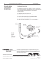
Document Update
(Catalog Number 1746-INT4)
To the Installer
Compliance with
European Union Directives
This publication states compliance with directives required for using
analog I/O modules with the CE mark within the European Union or
EEA regions. It also provides instructions for inserting a ferrite collar
on the module’s input cable(s) for compliant immunity to electrical
noise. Use these instructions as a supplement to the user manual,
publication 1746-6.16.
If this product has the CE mark, it is approved for installation within
the European Union and EEA regions. It has been designed and tested
to meet the following directives.
(Insert at the end of chapter 1.)
EMC Directive
This product is tested to meet Council Directive 89/336/EEC
Electromagnetic Compatibility (EMC) and the following standards,
in whole or in part, documented in a technical construction file:
EN 50081-2
EMC – Generic Emission Standard, Part 2 – Industrial Environment
EN 50082-2
EMC – Generic Immunity Standard, Part 2 – Industrial Environment
This product is intended for use in an industrial environment.
Low Voltage Directive
This product is tested to meet Council Directive 73/23/EEC
Low Voltage, by applying the safety requirements of EN 61131–2
Programmable Controllers, Part 2 – Equipment Requirements and Tests.
For specific information required by EN 61131-2, see the appropriate
sections in this publication, as well as the following Allen-Bradley
publications:
Industrial Automation Wiring and Grounding Guidelines
(for noise immunity), publication 1770-4.1
Automation Systems Catalog, publication B111
2
Thermocouple/mV Isolated Input Module
Wiring the Module
Document Update
Installing the Ferrite Collar
(Under this heading,
add this procedure at
the end of chapter 3.)
For immunity to electrical noise with this CE-marked module, insert
ferrite collar (Fair-Rite Inc. part number 0443164151) around the input
cables immediately beneath the module in the I/O chassis.
Do this as follows:
1. Bundle the cables at the module end.
2. Fold the collar so that it encircles the cables.
3. Press the plastic housing until the collar snaps together.
4. Check that the collar is fully latched.
5. If the collar slides on the cables, use a cable tie to secure it.
module in
I/O chassis
ferrite collar
before folding
bundle of cables
in open collar
ferrite collar:
part number
0443164151
Fair-Rite Inc.
PO Box J
1 Commercial Rd
Wallkill, NY 12589
(914) 895-2055
Place ferrite
collar here
ferrite collar after
folding and latching
Allen-Bradley, a Rockwell Automation Business, has been helping its customers improve
productivity and quality for more than 90 years. We design, manufacture and support a broad
range of automation products worldwide. They include logic processors, power and motion
control devices, operator interfaces, sensors and a variety of software. Rockwell is one of the
world’s leading technology companies.
Worldwide Representation
Allen-Bradley Headquarters, 1201 South Second Street, Milwaukee, WI 53204 USA, Tel: (1) 414 382-2000 Fax: (1) 414 382-4444
PN 955127-71
Publication 1746-6.16-DU1 – October 1996
Copyright 1996 Allen-Bradley Company, Inc. Printed in USA