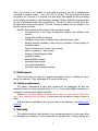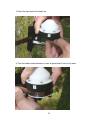
1
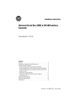
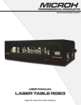
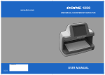
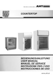
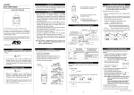
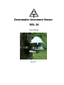
Denrometer Increment Sensor
DRL 26
User’s Manual
May 2007
Content:
1
General description ................................................................................ 3
2
Specifications ........................................................................................ 4
3
Operation.............................................................................................. 5
3.1
Sensor installation................................................................................ 5
3.2
Infrared communication ....................................................................... 5
3.2.1
Start operation............................................................................. 5
3.2.1.1 Basic setting ............................................................................ 5
3.2.1.2 Advanced setting ..................................................................... 5
3.2.1.3 After power drop-out................................................................ 6
3.2.2
Memory capacity.......................................................................... 6
3.3
Data processing................................................................................... 6
4
Maintenance.......................................................................................... 7
4.1
5
Battery replacement............................................................................. 7
Warranty............................................................................................... 7
Appendix A....................................................................................................... 9
Appendix B......................................................................................................11
2
1 General description
DRL 26 is designed for long-term registration of tree trunk circumference via
stainless tape that encircles the tree trunk. Its length variations are measured with a
rotary position sensor and stored into the datalogger memory in regular time periods.
Also, the internal temperature of the electronic part of the sensor is measured and it can
be stored into the memory, too.
The sensor is fixed to the trunk just by the strength of the tape – no sharp or
invasive fixing parts are used.
The sensor is made from UV resistant plastic, metal parts are made from stainless
steel or anodized aluminum. The internal space for the electronics is water-sealed.
The sensor is powered with a Lithium-ion battery for up to five years of continuous
measurement. The communication with PC is based on infrared transmission; however,
a special USB/IrDA adaptor is necessary for that (see Appendix A).
The datalogger memory stores up to 60,000 measured values what means more
than three years of both increment and temperature values stored in hourly intervals.
Both time intervals of measurement and storing to memory are generally different so
one value can represent the average of more readings.
The memory is non-volatile type so the measured data are safely stored even in
case of full battery discharge of battery damage. There are two memory operating
modes: (i) the oldest data are overwritten with the actual ones or (ii) the logger stops
operation when the memory is full.
Datalogger is supported with fancy graphical software for data viewing, preprocessing and export to common file formats (text, Excel). The software contains also
advanced statistic module intended for processing of long-time data series, user define
calculation and other options available for all EMS products.
3
2 Specifications
Increment sensors type
Range
Linearity
Resolution
Tape strength
Operating range:
- temperature
- humidity
Temperature sensor accuracy
Datalogging unit:
- memory capacity
- measuring interval
- averaging (storing) interval
- internal clock accuracy (-10 to 40°)
- input voltage resolution
Battery lifetime:
- storage time/idle run (logging stopped)
- when measured every 1 hr
- when measured every 10 minutes
Size
Weight (incl. battery)
rotary position
64 mm of circumference
2 % of full scale
1 µm
15 to 20 N in the whole range
- 30 to 60 °C
0 to 100 %
±2 deg.C
50,000 values typically
10 min to 24 hrs
10 min to 24 hrs
±1 min per month
16-bit
Lithium LS14250CN 3,6 V; 1000 mAh
ca 5.5 years
ca 5 year
3 years
100 x 70 x 100 mm
ca 300 g
4
3 Operation
3.1 Sensor installation
The unit is fixed to the tree trunk with the 12 mm wide stainless tape. The tape is
cut from the spool containing 15 m of tape by a light snips. Tape length should exceed
the trunk circumference for 25 cm. The installation procedure is shown in Appendix B.
Datalogger has no power switch. It is running after switching on the data logging by
software. The system configuration is made from the PC running the Mini32 software by
an infrared connection.
3.2 Infrared communication
The infrared connection and must be activated just before or after the first pushing
“Download”, “Data” or “Configuration” button in the Mini32 main screen. Than, the IR
connection is maintained until the program is closed or the connection is lost when the
IR beam is canceled for more that 15 seconds by an obstacle or by too long distance
between the transmitter and sensor.
The connection is established by putting the EMS USB/IrDA unit magnetic head near
the sensor IR transmitter. The right position is marked with IrDA label with a label on
the cylindrical sensor body. The distance between the magnetic head and the unit
necessary to start connection should be a few centimeters only (see Appendix B). The
typical working distance between sensor and transmitter is 60 cm within a 45o deflection
in all directions from the optical axis. Optical axis of IR transmitter crosses upright the
axis of sensor ca 1 cm above the IrDA label.
3.2.1 Start operation
3.2.1.1 Basic setting
Run Mini32 software which is a part of delivery. Push “Configuration” button and
activate IR connection by magnetic head. Set both interval of measurement and twocharacter device code.
Double click on a channel line opens a channel setting window. Set channel on and
add a description.
Left mouse click on ON/OFF button activates/deactivates data logging.
Press “Put” button in order to send the configuration to the datalogger.
3.2.1.2 Advanced setting
Push “More” button in “Configuration” window in order to approach advanced
setting screen. This option enables:
− Datalogger reset (initialization). Initialize resets all system variables to default
values, changes datalogger time and password, erases the data from memory and
sets the memory operation mode – see General description. System calls for
initializing automatically always when the supply voltage has dropped bellow
5
2.9 Volts, i.e. after battery replacement or after its total discharge. In such a case is
the user asked for initializing by each communication attempt. Warning – save data
always before initializing – they are lost afterwards!
− Memory erase (RAM clear) should be done when the memory is full and the data
overwriting is disabled and also when the data continuity is senseless or misleading –
when the sensor in moved to different location for instance. Make sure the data
were successfully saved before memory erasing!
− Hardcopy of memory (HCM). The whole memory content will be saved to file. Use it
in case of problem with data conversion after downloading which could be caused by
damaged data structure due to external factors. Send the file to producer for free
encoding.
− Password. A four-character string can be introduced. Password disables unauthorized
changes of configuration.
3.2.1.3 After power drop-out
It is necessary to initialize the datalogger always when the battery voltage drops
bellow 2.9 Volt. This comes usually after the battery replacement or after its removing.
See Advanced setting.
Note: The battery status is continuously calculated since the last low voltage
occurrence which normally indicates the battery replacement according the time of
operation (measurement, communication with PC, data download). Naturally, the full
capacity of the new battery is supposed. Therefore, the battery duration will be
overestimated in case of using a used one or very old battery. See also Battery
replacement.
3.2.2 Memory capacity
Maximum number of days of the measurement stored in memory can be easy
estimated according to formula
N = 50000/(n*k)
where
n = number of averaged values within a day
k = number of channels in use
Example: Stem increment and temperature values stored in memory each hour fill
up the memory after 2.9 years.
3.3 Data processing
EMS Mini32 universal software supports also the data handling and processing.
Data download and saving process is activated after pushing “Download” button. All
data from memory are saved in the file XY_2005_04_28.hex where XY is device code
(see Base setting) and 2005_04_28 is computer date (YMD). These *.hex file contains
the stored data and complete configuration information including the last battery
voltage, datalogger time in a compressed format suitable for fast transfer to computer.
6
Since this format is not usable for next data processing, the file is subsequently
converted to another format - *.dcv (XY_2005_04_28.dcv). This file contains the same
information as *.hex one, it is typically four time larger but suitable for fast processing
as file mixing and chaining, time averaging, drawing, editing, statistical processing etc.
In case of accidental wrong data processing in *.dcv file it is easy to create the *.dcv
file again after opening the original *.hex file. Therefore, please save the original *.hex
files for archive purposes.
Mini32 software allows a wide range of data operation, mainly:
- connection files of the same configuration coming from different time
periods
- mixing files of different systems
- calculation mean values of different time intervals (hours, days)
- drawing selected variables in time with the possibility of easy erasing of
irrelevant values
- export of data to text, Excel or Lotus format
- export of graphs to *.bmp format
- drawing of depth/height profiles
- printing of graphs
- basic statistical analysis
- regression data analysis
- user defined calculation
- non-linear multi-regression analysis
4 Maintenance
DRL 26 unit does not need any special maintenance. Avoid a shifting the senor
during the operation. Take advantage of IR access at this point.
4.1 Battery replacement
The battery replacement is easy after screwing-off the datalogger lid with the
electronics from the main cylindrical body. A 2.5 or 3 mm small-bladed screwdriver is
necessary for screwing the battery terminals.
Please short circuit the battery terminals with a metal tool (screwdriver, knife, door
key…) after removing the old battery to make sure that the battery energy counter is
reset.
After the battery replacement, the system needs to be initialized – see After power
drop-out.
5 Warranty
The producer warrants right function of the measuring system for three years after
it is accepted by a customer. All the faults will be removed free of charge during this
7
time, at the measuring device itself as well as at sensors. The producer is not
responsible for the faults originated by careless manipulation, incorrect operations,
wrong applications or theft. The warranty covers the battery failure for three months
only.
The fright to producer is paid by customer; the sending back is paid by producer.
8
Appendix A
EMS USB/IrDA cable
The EMS USB/IrDA cable serves basically as an ordinary USB/RS232 converting
cable with built-in infrared transceiver. The cable is necessary for all present notebooks
which are not equipped with serial COM port. The cable head has two LED diodes
indicating the communication process. The red one indicates the signal coming out of
computer, the greed LED diode traces the signal going out of datalogger.
Since the electronics of dataloggers is most of the time between following
measurements in idle mode (sleeping), it has to be waked up somehow in order to be
ready for communication. Normally it is made by a signal from a connected cable. IR
transceiver of systems with IR access is activated by the above mentioned magnetic
head. The magnetic field switched on a reed contact located close to IR access point
and the system wakes up for some time waiting for communication.
9
When the magnetic head is put on the serial connector, the infrared transceiver is
activated. This status is detected by Mini32 software after the first communication
attempt and the system use this way of data transfer until the Mini32 is closed.
The infrared data access has to be enabled in Mini32 COM port setting:
10
Appendix B
Installation notes
1/ Cut a piece of tape ca 25 cm longer than the stem circumference. Avoid
crumpling of the tape during the installation!
11
2/ Fold one end of the tape and put on the central pin
3/ Wrap the tape around the stem and than wrap it around the coil
12
4/ Insert the tape below the binder bar
5/ Turn the head counterclockwise in order to get at least 5 mm on the scale
13
6/ and fold the tape over the bar.
7/ The tape has to remain under tension – check the scale position.
14
8/ Activating of the IR connection – bring near but do not touch!
9/ The datalogger setting (example):
Refer to Mini32 user’s manual for necessary details.
Brno, May 2007
15