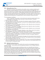
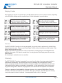
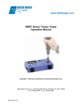
1
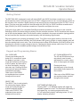
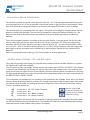
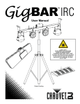
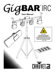
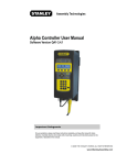
DELTA REGIS
Tools Inc.
BECT640-SSO Screwdriver Controller
Operation Manual
CAUTION - Please read, understand, and follow all operating and safety instructions in
this manual before using the BECT640-SSO controller.
This controller is designed for use exclusively with the following Delta Regis Brushless
Electric Screwdrivers:
CESL610-612, CESL623(F/P/PF), CESL624(P)
ESL628(F/P/PF), ESL629(P), ESL629(P)M - ESL650(P)M, ESP620-650
Do not attempt to use this controller with any other tools.
If you have any questions or concerns, please contact us at:
Delta Regis Tools, Inc.
3315 Industrial 25th St.
Ft. Pierce FL 34946
USA
Doc. BECT640-SSO_Manual_R0
Copyright © 2012 Delta Regis Tools, Inc
Ph +1-772-465-4302
Fx +1-772-465-4368
E-mail: [email protected]
Website: www.deltaregis.com
DELTA REGIS
BECT640-SSO Screwdriver Controller
Operation Manual
Tools Inc.
Important - Installation and Safety
Warning - Failure to understand and follow proper installation guidelines, safety requirements,
and operating instructions may result in malfunction, component damage, property damage,
shock hazard, fire hazard, injury or death.
1. Please read and understand the operation manual and follow all safety and operation instructions.
2. Place the controller in a suitable dry, indoor location. Do not use this controller in damp, wet or high
temperature environments. Do not use in the presence of flammable liquids or gases.
3. Ensure that the controller has proper ventilation. Do not expose the controller to areas subject to
airborne contaminants (eg. dust, metal filings).
4. Use only a properly grounded electrical outlet of the correct supply voltage to power the screwdriver
controller. Ensure that the supply outlet is overload protected and of sufficient amperage capacity.
5. Use only the correct plug for the controller and outlet. Hold the plug of the power cord when
connecting or disconnecting. Do not pull on the cable.
6. Do not expose the cable or controller to oil, chemicals, or heat. Ensure that the cable is routed and
used in such a manner as to not be subject to sharp objects that may abrade or cut the cable.
7. Locate the controller in a suitable, safe location on a steady surface. Do not place in a high location
where there may be a risk of it falling. Secure the controller in position to prevent possible movement
caused by pulling on the power or tool cables.
8. Do not cover the controller or stack any objects on top of or near the controller. Ensure that adequate
clearance and ventilation is provided around the perimeter of the controller.
9. The BECT640-SSO Controller is for use exclusively with Delta Regis brand screwdrivers as specified
on page 3. Use of this controller with any other tool may result in malfunction, damage, or injury.
10. In the event that the controller is overloaded beyond the maximum current rating, an internal fuse will
disrupt power. Should the controller stop functioning, or exhibit abnormal or intermittent operation,
please discontinue use immediately and send the controller to an authorized service centre for
troubleshooting and repair.
11. Excessive duty cycle will cause the tool and/or controller to overheat. If this occurs, discontinue use
until cooled down and reduce cycle rate. As a general rule, do not exceed 10-15 screws/minute.
12. The brushless screwdrivers incorporate a protection circuit which stops the electric screwdriver if
the tool is switched from forward to reverse while running. Should this happen, the operator must
release the tool trigger and restart the fastening cycle.
13. Turn the main power switch off when the controller is not being used. Unplug the controller if it is not
being used on a regular basis.
14. Do not attempt to disassemble or repair the screwdriver or controller. Repairs should only be
performed by qualified technicians properly trained in the safe operation, troubleshooting, and repair
of these devices. Please consult Delta Regis for the location of the nearest service depot.
15. Use only the factory specified Delta Regis brand replacement parts and accessories with these tools
and controllers.
16. Any damage to the tool and/or controller resulting from misuse, abuse, or failure to follow these
guidelines will void the limited product warranty.
Grounding - This controller (and AC power cord) is equipped with a 3-prong electrical receptacle/plug
with ground pin. The controller must be connected to a properly grounded AC electrical outlet. Do not
attempt to use this controller without a properly functioning ground connection. Never connect a live
circuit to the ground pin or internal yellow-green ground wire.
www.deltaregis.com
Page 2
DELTA REGIS
BECT640-SSO Screwdriver Controller
Operation Manual
Tools Inc.
Specifications
Model Number
Input
Output
Speeds
Use exclusively with screwdriver models:
BECT640-SSO
100-240V AC, 50/60Hz, ~6.3A
40 / 32 / 24 VDC, 220W
Hi / Lo (switch selectable)
CESL610-612, CESL623(P/F/PF),CESL624(P)
ESL628(P/F/PF), ESL629(P)
ESL629(P)M-ESL650(P)M, ESP620-650
Slow Start Function
Slow Start Time Adjustment
Slow Start Speed Adjustment
Selectable ON / OFF
0 - 9.9 seconds
30 - 100% of rated speed
Count Method (selectable)
Count Setting Range (rundowns/batch)
Count up to total / count down from total
1-99
Time Window Settings
Minimum acceptable rundown time
Maximum acceptable rundown time
0.00 - 9.90 seconds (0.01 sec increments)
0.0 - 9.9 seconds (0.1 sec increments)
Audible Alarm Settings (selectable)
‘On’ sounds when
‘OF‘ sounds when
‘FF’ sounds when
‘EF‘ sounds when
Good / No Good / Batch Complete
No Good
Batch complete / No Good
Good / Batch Complete
Input Connections
Remote enable (eg - part in position)
Clear (reset) count value
Output Connections
Rundown OK, Rundown NG, Batch Complete
Dimensions (L x W x H)
Weight
Approvals
248 x 130 x 100 mm
2.5 kg
CE/RoHS/ETL
Included Accessories
AC power cord, 32VDC adapter cable, Key for
program lock, User manual
www.deltaregis.com
Page 3
DELTA REGIS
Tools Inc.
BECT640-SSO Screwdriver Controller
Operation Manual
Controller Overview
SCREWDRIVER
HI/LO SPEED
SELECTOR
PROGRAM FUNCTION
KEY LOCK
Front Face of
Controller
SCREWDRIVER
CABLE CONNECTOR
KEYPAD AND INDICATORS
FOR PROGRAMMING AND
STATUS MONITORING
AC INPUT CABLE
RECEPTACLE AND
MAIN POWER
ON/OFF SWITCH
OUTPUT VOLTAGE
SELECT SWITCH
24/32 OR 32/40 VDC
DIP SWITCH FOR
SELECTING OPTIONAL
FUNCTIONS
INPUT/OUTPUT
CONNECTION
TERMINAL BLOCK
www.deltaregis.com
Rear Panel of
Controller
Page 4
DELTA REGIS
BECT640-SSO Screwdriver Controller
Operation Manual
Tools Inc.
Getting Started
The BECT640-SSO is designed to work with both 32VDC and 40VDC brushless screwdrivers. In order to
accomodate the series of tool being used, an OUTPUT voltage must be set via a covered selection switch on
the rear face of the controller. Slightly loosen (do not remove) the two screws securing the OUTPUT cover in
place. Pivot the cover down and move the slide switch left (24V-32V) for 32VDC brushless screwdrivers or
right (32V-40V) for 40VDC brushless screwdrivers. Reposition and tighten the cover.
Connect the 6-pin cable of a compatible Delta Regis brushless screwdriver from the tool to the controller.
Delta Regis 40VDC brushless tools plug directly into the controller connector. 32VDC brushless tools require
use of the included adapter cable. Ensure that the cable is installed in the proper orientation (spring guard at
tool end) and that the connectors are seated properly with the fastening rings secured.
Plug the controller into a properly grounded AC outlet. Turn ON the main power switch on the back of the
controller. The audible alarm will beep, the RUN indicator LED (green) will light up, and the display panel will
show the starting batch count value. One of the three output voltage LED indicators (24/32/40V) will be lit up,
indicating the controller’s output voltage to the tool. Changing the speed selector switch from HI to LO will
toggle between the two available speeds/voltages for that series of tool.
Keypad and Programming Basics
UP / DOWN ARROW KEYS
The UP and DOWN arrow keys
are primarily used to make
adjustments to numeric values
when in the program edit mode.
ON - CLEAR KEY
Pressing and holding the ON
button for 5+ seconds will cause
the display to go blank. In this
mode the screwdriver will function
at HI/LO speed, but there will be
no other functionality (counting,
slow start, etc). Pressing ON from
this mode will restore the display
and added functionality.
Other uses of ON/CLEAR
are explained where required
throughout this manual.
SELECT KEY
The SELECT key is used primarily
for entering the program editing
mode and cycling through the
available program settings.
Other uses of SELECT are
explained where required
throughout this manual.
Pressing both keys
simultaneously cycles through
the available sound options for
the controller.
Other uses of the ARROW keys
are explained where required
throughout this manual.
SOFTWARE KEYPAD LOCK
Pressing SHIFT + UP ARROW together will toggle the
software keypad lock on/off. This lock limits functionality of
the keypad (eg - no entering program edit mode).
‘LC’ will momentarily display, indicating locked. ‘Un’ will
display indicating unlocked.
www.deltaregis.com
Page 5
DELTA REGIS
BECT640-SSO Screwdriver Controller
Program Options and Editing
Tools Inc.
SEQUENCE NUMBER (SL)
There are 5 programmable screw fastening sequences (SL=’01’ to ‘05’) available. In many cases, only the first
sequence (01) will be needed. If the screwdriver is used to install a batch of fasteners with varying requirements,
multiple sequences may be necessary. For example, if an assembly requires the installation of 4 screws, where
3 screws are short and 1 screw is long, the controller can be programmed with 2 unique sequences - a sequence
for the short screws and one for the long screws. This would allow different time windows to be set-up for the two
different screw lengths. Each sequence must be programmed separately, and numbered in the order that the screws
will be installed (starting with Sequence 01). In this example, if the 3 short screws are to be installed first, enter
the program for Sequence ‘01’ with a batch quantity of 3 and time parameters for the short screw. Then repeat the
program steps for Sequence ‘02’ with a batch quantity of 1 and the time parameters for the long screw. Finally,
program Sequence ‘03’ with a batch quantity of ‘00’ to signify that there are no further fasteners to install.
(For multiple sequences, refer also to info on setting dip switch #6 on pg. 11).
BATCH COUNT SETTING (SC)
Enter the desired number of fasteners to be installed per batch. Depending on the setting of DIP switch #1, the
display will either count down from the total batch value entered, or count up to the total batch value. The count will
only increment (and indicate a ‘GOOD’ rundown) if the rundown cycle falls within the limits set by the min and max
rundown time settings (see below). When all fasteners in the batch have been installed, the controller will indicate that
the batch is complete and the count will reset for the next cycle.
If, after a good rundown, the operator runs the screwdriver in reverse, the batch count value will decrement by a
count of one (based on the assumption that the operator is removing the last installed fastener).
The batch count can be reset to begin a new batch by pressing the ON/CLEAR key.
END OF BATCH RESET TIME (Rt)
When a rundown batch is completed, the controller provides a visual indication (OK light) and audible indication
(depending on audible settings) that the batch is complete, followed by a reset of the display count for the beginning
of the next batch. The END OF BATCH RESET TIME value determines how long these indicators will stay on before
the batch count resets. Please note that the screwdriver can not be operated during this reset time period.
SLOW START TIME (RC) and SLOW START SPEED (SP)
Please refer to the section entitled ‘Screwdriver Speed Adjustments’ for further information on the Slow Start function.
MAXIMUM AND MINIMUM RUNDOWN TIME SETTINGS (Ht, Lt)
The controller determines whether a fastener rundown is deemed GOOD (OK) or NO GOOD (NG) by comparing the
actual time taken for the rundown cycle to a time window programmed by the user. For example, a cross threaded
screw will cause the screwdriver to shut-off too early (before min time) and a stripped screw will cause the driver to
run too long (beyond max time).
GOOD (OK)
NO GOOD (NG)
Cycle
Start
MIN Time
NO GOOD (NG)
Time (seconds)
MAX Time
If the fastening cycle completes (clutch trips) within the programmed time window, the
rundown cycle will be accepted as GOOD (OK) and the batch count will increment.
RECONFIRM TIME (LL)
If the assembly process requires that the operator has the ability to ‘double-hit’ the fastener (release and retrigger the
screwdriver on a fastener that has just been installed), a reconfirm time can be programmed into the control. During
this time period (which immediately follows the completion of the rundown), the operator is able to re-trigger the tool
without causing a No Good (NG) error signal to be generated. Slow Start speed (SP) must be set to a value of ‘L0’
for this function to be available, so that the tool has full power to run the re-hit cycle.
www.deltaregis.com
Page 6
DELTA REGIS
START - EDIT
PROGRAM
Tools Inc.
Press and hold SELECT
for about 5 seconds
SEQUENCE LIST
until ‘SL’ displays.
(5 available sequences)
Release to view
programmed value.
Press until
‘SC’ displays.
Release to
SCREW BATCH COUNT
view value. (# of screws per batch)
Press until
‘Rt’ displays.
Release to
view value.
Press until
‘RC’ displays.
Release to
view value.
Press until
‘Lt’ displays.
Release to
view value.
(select # to edit)
Adjust value
UP / DOWN
MIN = 00 screws
MAX = 99 screws
Adjust value
UP / DOWN
Notes and Guidelines:
Programming Mode Locks
To view / edit the sequences, the KEY
LOCK must be unlocked and the software
lock (toggled by pressing SELECT+UP
simultaneously) must also be unlocked
(Un). If the lock is on when you attempt
to enter programming an LC will be
displayed.
(Rt) Batch Reset Time
At batch completion, the screwdriver will
not operate for the length of the batch
reset time setting.
BATCH RESET TIME
(delay after batch OK)
SLOW START TIME
(length of slow start)
Press until
‘SP’ displays.
Release to
SLOW START SPEED
view value.
(percent of run speed)
Press until
‘Ht’ displays.
Release to
view value.
SEQUENCE # 01-05
BECT640-SSO
HIGH TIME SETTING
(max. rundown time)
0.0 - 9.9 seconds
(tool will be inactive)
0.0 - 9.9 seconds
(set < rundown time)
L1 (slow) - L9 (fast)
L0 = slow start off
0.1 - 9.9 seconds
(cycle NG if time > Ht)
Adjust value
UP / DOWN
Adjust value
UP / DOWN
Adjust value
UP / DOWN
Adjust value
UP / DOWN
(RC) Slow Start Time
The slow start time must be less than the
time required to install the screw. The tool
must switch to full speed before the clutch
activates for shut-off.
(SP) Slow Start Speed
Slow start speed is adjustable in steps
from lowest (L1 ~ 30% of full spd) to
highest (L9 ~ 85% of full spd). L0 equals
100% of run speed or slow start off.
(Ht) High Time and (Lt) Low Time
The Ht and Lt settings establish a time
window for OK/NG evaluation of a fastener
rundown. Low Time (Lt) must be set to a
value lower than High Time (Ht) during
programming or an error will occur. Ht
value must be > Lt.
(LL) Re-Hit Screw Time
Programming of the (LL) value is only
available if Slow Start Speed (RC) is set to
L0 (slow start off). The re-hit function can’t
be used if slow start is set between L1-L9.
EXIT PROGRAM
MODE
LOW TIME SETTING
(min. rundown time)
Press until
‘LL’ displays.
Release to
RE-HIT SCREW TIME
view value. (re-hit after tightening)
3 digit value, 0.00 - 9.90 seconds, format ‘x.xx.’ Adjust value
ON/CLR to toggle left/right, value shown = 1.25 UP / DOWN
3 digit value, 0.00 - 9.90 seconds, format ‘x.xx.’ Adjust value
ON/CLR to toggle left/right, value shown = 0.50 UP / DOWN
The final option displayed will be
either ‘Lt’ or ‘LL’ (depending on the
setting of ‘SP’). Once the final value
is adjusted, press SELECT to return to
normal operation.
Page 7
DELTA REGIS
BECT640-SSO Screwdriver Controller
Operation Manual
Tools Inc.
Screwdriver Speed Adjustments
The controller provides two speed control options for the tool - HI/LO running speed and optional slow start.
A running speed of HI or LO may be selected via the rocker switch on the front face of the controller. Please
refer to the screwdriver catalog specifications for the tool’s free speed RPM at the HI and LO settings.
The controller also has a selectable slow start option. This option can be helpful in engaging screw threads
properly to avoid cross-threading. The slow start is intended for initiating the fastener rundown only - the
slow start time must be limited so that the tool switches to full speed before the fastener completes its
rundown.
There are two separate variables for setting up the slow start function - time and speed. Set the slow start
time by entering the desired slow start time value (0.0-9.9 sec) for function ‘RC’ during the programming
sequence. Set the slow start speed by selecting a value for function ‘SP’. You can choose between values
of L1-L9 (30% ~ 85% of screwdriver free speed rpm) or L0 (100%). Exit the program mode and engage the
start (trigger or push) mechanism on the screwdriver to check settings. Repeat until the desired result is
achieved.
Refer to the programming flow chart (pg 7) for further details on entering parameters.
Audible Alarm Settings / OK and NG Lights
Along with the two digit count display, the controller also provides visual and audible indication of rundown
OK, rundown NG, and batch complete.
The OK (green) and NG (red) lamps indicate whether the rundown was GOOD or NO GOOD. If the rundown
is within the set parameters, the OK lamp will light up at the end of the rundown cycle. If the rundown is no
good, the NG lamp will light at the end of the rundown. When the fastening batch is completed, the OK lamp
will light up and the batch count value will reset after a time delay determined by the value programmed into
the END OF BATCH RESET TIMER.
To suit individual user preferences, four variations of the audible alert are available. When active, the audible
alert provides a single short beep for rundown OK, a single long beep for batch complete, three short beeps
for rundown NG (below MIN time setting) and five short beeps for rundown NG (above MAX time setting).
The four selectable settings are:
ON
OF
FF
EF
sounds when... OK / NG / Batch Complete
sounds when... NG
sounds when... NG / Batch Complete
sounds when... OK / Batch Complete
Press the UP & DOWN
arrow keys simultaneously
to choose the next available
audible alarm setting.
To change the audible alert setting, with the controller in operating mode (not in programming mode), press
the UP and DOWN arrow keys simultaneously. The controller will loop to the next available audible setting
and show the new current audible setting value in the display.
www.deltaregis.com
Page 8
DELTA REGIS
BECT640-SSO Screwdriver Controller
Operation Manual
Tools Inc.
Input / Output Connector
COM (0VDC)
An input/output connector is provided on the
back face of the controller for interfacing signals
with external equipment.
OK ALL output (dry contact)
NG output (dry contact)
V+
DC voltage (+12VDC, 1A max) available if
required to power external circuits
OK output (dry contact)
CLEAR input
OK
Outputs a signal when an acceptable (GOOD)
rundown cycle is completed
GATE / ENABLE input
COM (0VDC)
ON
OK ALL output
OFF
NG output
NG
Outputs a signal when an unacceptable (NG)
rundown cycle occurs
OK output
V+ (12VDC, 1A max)
ON
OFF
Output Terminals
OK ALL
Outputs a signal when the batch is completed
ON
OFF
COM
Common (0VDC) - used when wiring in external
input switches, V+ supply, or transistor outputs
GATE
Input for external switch(es) verifying that the
driver can be enabled to begin a new batch.
The controller’s use of external switches is
dependent on DIP Switch Settings. Please see
next page for further details.
CLEAR
Input for external resetting of the batch count
ON
OFF
OUTPUT TERMINALS 2,3 and 4
Connections 2, 3, and 4 are open collector
transistor outputs (NPN, sinking outputs). DO
NOT EXCEED 24VDC/10mA power to drive
these outputs. Outputs tied internally to COM 5.
OUTPUT TERMINALS 8 to 13
Connection pairs 8/9, 10/11 and 12/13 are dry
relay contact outputs (AC/DC 60V, 400mA max).
Input Terminals
INPUT TERMINALS 6 and 7
Connect an external switch contact between
COM terminal 5 and one of the inputs (6 or 7).
Closing the contact from 5 to 6 will ENABLE the
driver at cycle start, closing the contact from 5
to 7 will send a CLEAR signal to the controller.
Input functionality depends on DIP switch
settings. See next page for details.
DO NOT SUPPLY POWER TO INPUTS.
www.deltaregis.com
Page 9
DELTA REGIS
BECT640-SSO Screwdriver Controller
Operation Manual
Tools Inc.
DIP Switch Settings
There is a 7-position DIP Switch mounted in the rear face of the controller,
next to the I/O Connector. The controller is shipped from the factory with all
switches in the OFF (down) position. Please refer to the following guide to
select the proper switch positions to suit your specific application.
SW 1 - Counting Method
Determines whether the controller counts up from zero to the programmed batch value, or
counts down from the batch value to zero. OFF = Count Down, ON = Count Up
SW 2 - External Switch (GATE Input)
If the process requires that an external input signal be present (at the GATE input) to allow the
screwdriver to enable to start a new batch, then SW2 must be in the ON position. When SW2 is OFF,
the external GATE input signal is not required. Refer to the diagrams below (SW 4 description) for
further details on input signals and signal logic.
SW 3 - Manual Confirm to Reset Batch
With SW3 in the OFF position, the controller automatically resets to begin a new counting
batch after completion of the previous batch. Placing SW3 in the ON position will require the operator
to press the SELECT button at the end of each batch before the controller will reset to run a new
batch. Upon batch completion, the LED display will flash ‘C3’ and the screwdriver will be disabled until
the SELECT button is pressed.
SW 4 - Multiple External Switch Inputs (GATE Input)
In some instances, it may be desireable to interface two external input switches wired in
parallel to the GATE input. As an example, one switch might be triggered by a finished part leaving the
assembly station while the other is triggered by a new part entering the station. With SW4 in the OFF
position (and SW2 ON), one external switch signal is required to enable the screwdriver. With SW4 in
the ON position (and SW2 ON), two external switch signals are required to enable the driver.
1 External Signal at GATE Input
(DIP SW2 on / SW4 off)
Last batch
completed
Waiting for input,
driver disabled.
2 External Signals at GATE Input
(DIP SW2 on / SW4 on)
Last batch
completed
Batch resets,
driver enabled
Display flashes ‘C1’
Waiting for input,
driver disabled.
Batch resets,
driver enabled
Display flashes ‘C2’
External Signal ON
External Signal ON
(GATE Input) OFF
(GATE Input)
OFF
Input
Signal 1
Input
Signal
www.deltaregis.com
Input
Signal 2
Page 10
DELTA REGIS
Tools Inc.
BECT640-SSO Screwdriver Controller
Operation Manual
SW 5 - Evaluate Rundown Time
When SW 5 is moved to the ON position, the controller enters a rundown evaluation mode,
which can assist in determining proper time window settings to program for the application. The
operator will be allowed to run multiple rundown cycles (as many as desired) and the display will show
the actual cycle time for each rundown. Certain program parameters must be entered after SW 5 is
turned on, before the actual testing can start. Please keep in mind that the fastener rundown time will
change if any adjustments are made to running speed (Hi/Lo), slow start speed, or slow start time. It is
important that these adjustments are finalized before using this rundown evaluation procedure.
The test sequence is as follows:
(Note: The parameter setup portion of this test follows the standard programming flow chart
outlined earlier in the manual. Please refer back for further information, if required.)
1. Move DIP SW5 to the ON position.
2. The display flashes a numeric value - this value is the sequence number (SL) that the controller
will use for setup of the rundown parameters. If you wish to use a different sequence number, use
the UP/DN arrow keys to change.
3. Press SELECT. ‘SC’ will show in the display, followed by a value. Adjust the value to the desired
‘batch count setting’ for your application.
4. Press SELECT. ‘Rt’ will show in the display, followed by a value. Adjust the value to the desired
‘end of batch reset time’ for your application.
5. Press SELECT. ‘RC’ will show in the display, followed by a value. Adjust the value to the desired
‘slow start time’ for your application.
6. Press SELECT. ‘SP’ will show in the display, followed by a value. Select a value for the desired
slow start speed (L0-L9). Refer to pg 8 for further details on speed settings.
7. Press SELECT. The display shows ‘0.0’. The tool is now ready to run tests. Use the screwdriver to
rundown the fastener on the application. The display will count up time in 0.1 second increments
until the cycle completes. Once complete, the cycle time will show in the display. Repeat the
rundown as many times as desired.
8. Move SW5 to the OFF position. The controller will program the last recorded rundown time as the
sequence’s Max. Acceptable Rundown Time (Ht) value. The controller returns to normal operation
mode and displays the batch count value.
9. Enter the Programming Mode (press and hold SELECT for 3 sec) to review/verify the settings and
make any final adjustments to the time window values. Please refer to the programming flow chart
for further details on settings and values.
SW 6 - Multiple Rundown Sequences
With SW6 in the OFF position, the controller will run only the current program sequence to
complete the batch - it will not step to the next programmed sequence, even if multiple sequences
have been entered.
If you have multiple sequences programmed which you wish to run sequentially (see Sequence
Number (SL) on the programming page), setting SW6 to ON will cause the controller to step through
the programmed sequences in order until they have all been completed. A batch complete signal
will be output once all sequences have completed, and the controller will loop back to the start of
sequence SL01 to start the next batch. Note - if the controller encounters a sequence with a screw
batch count (SC) entered as zero, the controller identifies this as the end of the batch sequences and
will loop back to the beginning to start a new batch.
www.deltaregis.com
Page 11
DELTA REGIS
BECT640-SSO Screwdriver Controller
Operation Manual
Tools Inc.
Display Codes
When waiting for operator or external input, the LED display will show one of a series of codes, depending
on the DIP switch settings and the expected input. Further explanation is provide below.
Waiting for input from a single external
switch connected to GATE input.
Waiting for input from 1 external switch
and manual SELECT/CONFIRM.
DIP Settings - SW2(On), SW3(Off), SW4(Off)
DIP Settings - SW2(On), SW3(On), SW4(Off)
Waiting for input from two external
switches connected to GATE input.
DIP Settings - SW2(On), SW3(Off), SW4(On)
Waiting for operator to press SELECT/
CONFIRM to verify batch reset.
Waiting for input from 2 external
switches & manual SELECT/CONFIRM.
DIP Settings - SW2(On), SW3(On), SW4(On)
Waiting for operator to press CLEAR.
DIP Settings - SW2(Off), SW3(On), SW4(Off)
Error detected during input of
confirmation signal. Press SELECT/
CONFIRM again to acknowledge.
Incorrect set-up during programming
mode. Example ‘Lt (min time) value
entered is > Ht (max time) value’.
Service
The BECT640-SSO Controller is not user serviceable. Any repairs must be performed by a Delta Regis
authorized service center. Please consult Delta Regis Tools for further information and the location of the
nearest authorized service center.
Repairs to brushless DC screwdrivers must be performed by trained personnel, knowledgeable and
qualified in the repair of DC electric screwdrivers. Use only genuine Delta Regis parts when servicing
these products.
Do not attempt to modify the tools or controllers.
Warranty
The BECT640-SSO Controller is warranted for one year from the date of purchase against defects in
material and workmanship. This warranty does not cover damage due to transportation, abuse,
misuse, or improper service. Our sole remedy is to repair or replace (at our discretion) any unit found
to be defective due to defects in material or workmanship. It is the responsibility of the user to return
any product thought to be defective, freight prepaid, to our warehouse for inspection and evaluation.
There is no warranty of merchantability or fitness of purpose. In no event will Delta Regis Tools, Inc.
be liable for business interruptions, loss of profits, harm, injury, damage, personal injury, cost of delay,
or any other special, indirect, incidental, or consequential losses, costs, or damages.
www.deltaregis.com
Page 12