1
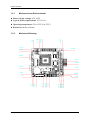
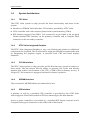
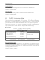
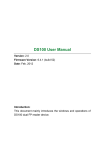
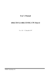
PEB-1431V
Embedded System Board
User’s Manual
P/N: B8980770
Version 1.0
Copyright © Portwell, Inc., 2002. All rights reserved.
All other brand names are registered trademarks of their respective owners.
Preface
EC Declaration of Conformity
(To Be Added)
For the following equipment:
Product Name:
Model Name:
Trade Name:
is herewith confirmed to comply with the requirements set out in the Council
Directive on the Approximation of the Laws of the Member States relating to
Electromagnetic Compatibility Directive (89/336/EEC). The equipment was
evaluated and passed the test, the following standards were applied :
EMC :
EN 55022
EN 50082-2
EN 61000-4-2
EN 61000-4-3
EN 61000-4-4
EN 61000-3-2
EN 61000-3-3
(1994/A1:1995 Class A)
(1991)
(1995)
(1996)
(1995)
(1995)
(1995)
The following manufacturer is responsible for this declaration :
Portwell, Inc.
(Company Name)
3F, No.88, Sec.1, Nei-Hu Rd., Taipei, Taiwan, R.O.C.
(Company Address)
Taipei, R.O.C.
Place
Date
Legal Signature of
Authorized Person
Preface
Table of Contents
How to Use This Manual
Chapter 1 System Overview.......................................................................................................1-1
1.1 Introduction................................................................................................................................. 1-1
1.2 Check List .................................................................................................................................... 1-2
1.3 Product Specifications................................................................................................................ 1-2
1.3.1 Mechanical and Environmental ...................................................................................... 1-4
1.3.2 Mechanical Drawing......................................................................................................... 1-4
1.4 System Architecture ................................................................................................................... 1-5
1.4.1 TPC Atlas............................................................................................................................ 1-5
1.4.2 STPC Atlas Integrated Graphics...................................................................................... 1-5
1.4.3 PC/104 Interface................................................................................................................ 1-5
1.4.4 SDRAM Interface............................................................................................................... 1-5
1.4.5 IDE Interface ...................................................................................................................... 1-5
1.4.6 STPC Atlas and Winbond W83977F-A........................................................................... 1-6
1.4.7 Compact Flash Interface ................................................................................................... 1-6
Chapter 2 Hardware Configuration ...........................................................................................2-1
2.1 Jumper Setting............................................................................................................................. 2-1
2.2 Connector Allocation ................................................................................................................. 2-2
Chapter 3 System Installation....................................................................................................3-1
3.1 Graphic Driver installation for STPC Atlas integrated GRAPHICS................................................. 3-1
3.2 IDE Interface................................................................................................................................ 3-1
3.3 SDRAM Interface ........................................................................................................................ 3-1
3.4 Compact Flash interface ............................................................................................................ 3-2
3.5 Watch Dog Timer Programming .............................................................................................. 3-2
Chapter 4 BIOS Setup Information............................................................................................4-1
4.1 Entering Setup............................................................................................................................. 4-1
4.2 Main Menu .................................................................................................................................. 4-2
4.3 Standard CMOS Features Setup ............................................................................................... 4-3
4.4 IDE Adaptors Setup Menu ........................................................................................................ 4-4
4.5 Advanced BIOS Features Setup................................................................................................ 4-6
4.6 Advanced Chipset Features Setup ........................................................................................... 4-8
4.7 Integrated Peripherals.............................................................................................................. 4-10
4.8 Power Management Setup ...................................................................................................... 4-12
4.9 PnP/PCI Configuration Setup ................................................................................................ 4-14
4.10 Default Menu .......................................................................................................................... 4-16
4.11 Setup Password....................................................................................................................... 4-16
4.12 Exiting Seleting ....................................................................................................................... 4-17
4.13 POST Messages ....................................................................................................................... 4-17
4.14 BIOS POST Check Point List ................................................................................................. 4-22
4.15 Flash BIOS Utility ................................................................................................................... 4-28
Appendix A
Appendix B
Preface
How to Use This Manual
The manual describes how to configure your PEB-1431V system to meet various
operating requirements. It is divided into four chapters, with each chapter
addressing a basic concept and operation of Single Board Computer.
Chapter 1 : System Overview. Presents what you have in the box and give you an
overview of the product specifications and basic system architecture for this model
of single board computer.
Chapter 2 : Hardware Configuration. Shows the definitions and locations of
Jumpers and Connectors that you can easily configure your system.
Chapter 3 : System Installation. Describes how to properly mount the CPU, main
memory and CF flash disk to get a safe installation and provides a guide of Watch
Dog Timer function.
Chapter 4 : BIOS Setup Information. Specifies the meaning of each setup
parameters, how to get advanced BIOS performance and update new BIOS. In
addition, POST checkpoint list will give users some guidelines of trouble-shooting.
The content of this manual and EC declaration document is subject to change
without prior notice. These changes will be incorporated in new editions of the
document. Portwell may make supplement or change in the products described in
this document at any time.
Updates to this manual, technical clarification, and answers to frequently asked
questions will be shown on the following web site : http://www.portwell.com/.
System Overview
Chapter 1
System Overview
This manual describes in detail the Portwell PEB-1431V PC/104 Embedded System
Board. This manual aims to provide all necessary information to users who may
interest in using all PEB-1431V’s functions.
Please be aware that it is possible to create configurations within the CMOS RAM
that make booting impossible. If this should happen, clear the CMOS settings, (see
the description of the Jumper Settings for details).
We strongly recommend that you study this manual carefully before attempting to
alter PEB-1431V’s configurations. In the case, something in this manual is not clear
or users have any suggestion on this manual. Contact our Customer Service
department with the relevant details. Portwell Technical Service Group’s web site
is http://www.portwell.com/.
1.1
Introduction
The PEB-1431V is a compact PC/104 CPU Module that equips with STPC Atlas lowpower processor and integrated VGA.
This model is incredibly compact with flexible extension. There is a PC/104
interface, which is cable to add extra devices. For an embedded system, Watch Dog
Timer is also one standard feature. It helps to free the system from undesired
hanging without human interface. This is unique for many Embedded System
applications.
Other features include a built-in TFT LCD interface, a compact Flash socket for type
II Compact Flash storage card, two serial ports, one parallel port, and on board
16MB of SDRAM.
PEB-1431V User’s Manual
1-1
System Overview
1.2
Check List
The PEB-1431V package includes the following basic items accompany with this
manual.
1 PEB-1431V All-in-One STPC Atlas Computing Module
1 User’s Manual
1 CD-ROM contains the followings:
- VGA drivers and utilities
- Other driver and utilities (if have)
Cable set includes the followings:
- 1 PS/2 keyboard and mouse Y cable (10-pin, Mini-DIN)
- 1 IDE 2.5” HDD cable (44-pin, pitch 2.0mm, connect two IDE devices)
- 1 FDD cable (34-pin, pitch 2.0mm)
- 1 bracket with one Printer port cable (26-pin, pitch 2.0mm)
If any of these items is damaged or missed, please contact your vendor and save all
packing materials for future replacement and maintenance.
1.3
Product Specifications
Main processor
Onboard STPC Atlas 133MHz, BGA package
BIOS
AMI 256KB Flash BIOS
Chipset
STPC Atlas integrated
I/O chipset
Winbond W83977F-A
Memory
Onboard 16 Mbytes SDRAM
Enhanced IDE
Supports two IDE devices. Supports PIO mode 3 & 4 with data transfer rate up to
22MB/sec.
FDD interface
Supports up to two floppy disk drives, 5.25" (360KB and 1.2MB) and/or 3.5"
(720KB, 1.44MB, and 2.88MB)
Parallel port
Interface for bi-directional parallel port x 1. Supports SPP, ECP, and EPP modes
PEB-1431V User’s Manual
1-2
System Overview
Serial port
One external D-SUB 9 connector supports RS-232
One external D-SUB 9 connector supports RS-422/485
KB/Mouse connector
Internal header PS2 Keyboard/Mouse connector x 1
Watchdog timer
Support watchdog timer from 0.5 to 64 sec by hardware count & software trigger
DMA
7 DMA channels (8237 equivalent)
Interrupt
15 interrupt levels (8259 equivalent)
Power management
I/O peripheral devices support power saving and doze/standby/suspend modes
APM 1.2 compliant
Display chipset
STPC Atlas integrated
Display memory
Shared display memory up to 4MB
Display type
Supports interlaced or non-interlaced CRT
Support for VGA and SVGA active matrix TFT flat panels with 9,12,18-bit
interface
Resolution
Up to 1280x1024x75Hz CRT display
Programmable panel size up to 1024 by 1024 pixels
SSD interface
One CF socket supports Type II Compact Flash Card (Support 8-320MB Compact
flash)
Expansion interface
One 8-bit 104-pin connector onboard
Power connectors
4-pin FDD x 2
PEB-1431V User’s Manual
1-3
System Overview
1.3.1
Mechanical and Environmental
Power supply voltage: ±5V, ±12V
Typical power requirement: +5V @ 1.6A
Operating temperature: 32 to 131°F (0 to 55°C)
Board size: 96mm x 90mm
90.82
30.66
21.02
Mechanical Drawing
5.08
1.3.2
90.17
85.09
82.55
63.63
52.2
39.88
28.32
26.67
8.89
6.35
0
PEB-1431V User’s Manual
85.74
90.82
95.89
53.02
45.09
35.37
12.5
0
5.08
5.08
1-4
System Overview
1.4
System Architecture
1.4.1
TPC Atlas
The STPC Atlas system on chip provide the basic functionality and buses of the
system:
Interface to SDRAM, 64-bit data bus. PCI interface provided by STPC Atlas.
VGA controller with video memory shared with system memory (UMA).
IDE interface support Ultra DMA. Tow connectors are provided: A 44 pin pitch
2.0mm standard IDE interface on the primary controller and a Compact Flash
connector on the secondary controller.
1.4.2
STPC Atlas Integrated Graphics
The STPC Atlas integrated Graphics is very cost efficient since almost no additional
components are required. This is achieved by using the SDRAM as frame-buffer and
by integrating the graphics engine. It provides both CRT and Panel display
interfaces.
1.4.3
PC/104 Interface
The STPC Atlas system on chip provides an ISA Bus that may operate in master or
slave mode. The bus master has the ability to generate bus cycles and thereby
transfer data without involvement of the CPU or DMA (Direct memory access). A
104-pin PC/104 connector is equipped onboard for future expansion.
1.4.4
SDRAM Interface
This on board 16 MB SDRAM are recommended to use.
1.4.5
IDE Interface
A primary as well as a secondary IDE controller is provided by the STPC Atlas
which supports Ultra DMA mode and PCI bus mastering for the data transfer.
Access to these controllers is provided by a standard IDE 44-pin connector and a
Compact Flash type II connector on the solder side of this board.
PEB-1431V User’s Manual
1-5
System Overview
1.4.6
STPC Atlas and Winbond W83977F-A
The STPC Atlas integrated Super I/O chip provides most input / output interfaces
of the system as the following:
COM 1. A RS-232 driver is used whereby RS-232 are provided. Driver uses charge
pumps whereby only +5V is required
COM 2. A RS-422/485 driver is used whereby RS-422/485 are provided.
Selection of the mode is made by hardware jumper
LPT. Support for SPP, EPP and ECP modes
Floppy interface
Keyboard interface
PS/2 Mouse interface
Provision of buffered ISA data bus for BIOS
NVRAM with battery backup for BIOS configuration and real time clock
1.4.7
Compact Flash Interface
A Compact Flash type II connector is connected to the secondary IDE controller. The
Compact Flash storage card is IDE compatible. It is an ideal replacement for
standard IDE hard drives. The solid-state design offers no seek errors even under
extreme shock and vibration conditions. The Compact Flash storage card is
extremely small and highly suitable for rugged environments, thus providing an
excellent solution for mobile applications with space limitations. It is fully
compatible with all consumer applications designed for data storage PC card, PDA,
and Smart Cellular Phones, allowing simple use for the end user. The Compact Flash
storage card is O/S independent, thus offering an optimal solution for embedded
systems operating in non-standard computing environments. The Compact Flash
storage card is IDE compatible and offers various capacities.
The following block diagram shows the architecture and main components of PEB1431V.
PEB-1431V User’s Manual
1-6
System Overview
Parallel Port
BIOS
Super I/O
W83977F-A
(128 PQFD)
PS/2 Keyboard
Mouse
Floppy
ISA BUS
MEMORY (16MB Onboard)
TFT
STPC
Atlas
Serial Port
COM 1/2
(516BGA)
VGA
EIDE
USB (Optional)
Figure 1-1
PEB-1431V System Block Diagram
The two key components on board are the STPC Atlas and the Windbond Super I/O
chip. These two devices provide the ISA and PCI bus to which all the major
components are attached.
PEB-1431V User’s Manual
1-7
Hardware Configuration
Chapter 2
Hardware Configuration
This chapter indicates jumpers’, headers’ and connectors’ location. Users may find
useful information related to hardware settings in this chapter. The default settings
are indicated with a star sign (Ì).
2.1
Jumper Setting
The jumper settings are used to select options for different features. The adjustment
made aims to let users customize PEB-1431V’s features. In the following sections,
short means covering a jumper cap over jumper pins; open or NC (Not Connected)
means removing a jumper cap from jumper pins.
1
Figure 2-1
JP3
Jumper Location Diagram
JP1: Watch Dog Time Function
JP1
1-2 Short
1-2 Open
3-4 Short
3-4 Open
Function
Disable WDT FunctionÌ
Enable WDT Function
Allocate I/O port 543/343
Allocate I/O port 533/033Ì
PEB-1431V User’s Manual
2-1
Hardware Configuration
5-6
Short
Short
Short
Short
NC
NC
NC
NC
7-8
Short
Short
NC
NC
Short
Short
NC
NC
9-10
Short
NC
Short
NC
Short
NC
Short
NC
Time-out Interval
0.5 Sec
1 SecÌ
2 Sec
4 Sec
8 Sec
16 Sec
32 Sec
64 Sec
JP2: CMOS Clear
JP2
1-2 Short
2-3 Short
Function
Normal Ì
Clear CMOS
JP3: COM2 RS-422/485 Selection Jumper
JP3
1-2 Short
2-3 Short
2.2
Function
COM2 RS-422Enable Ì
COM2 RS-485Enable
Connector Allocation
Figure 2-2
PEB-1431V User’s Manual
Connector Location Diagram
2-2
Hardware Configuration
Connector’s Function List
Connector Location
J1
J2
J3
J4
J5
J6
J7
J8
J9
J10
J11
J12
J13
J14
Description
Two USB Connector
PS/2 Keyboard& Mouse connector
IDE Interface Connector
D-SUB 9 pin connector (COM1)
+5V, +12V Power Connector
-5V, -12V power connector
D-SUB 9 pin connector (COM2)
VGA Connector
Parallel Port Connector
CPLD 8-pin connector
TFT LCD Panel Connector
Floppy disk interface
Reset Header
Compact Flash Socket
Pin Assignments of Connectors
J1: Two-port USB Interface Connector (2 x 5 shrouded header)
PIN No.
1
3
5
7
9
Signal Description
+5V
USBD0USBD0+
GND
GND
PIN No.
2
4
6
8
10
Signal Description
GND
GND
USBD1+
USBD1+
+5V
J2: PS/2 Keyboard/Mouse Connector (2 x 5 shrouded header)
PIN No.
1
2
3
4
5
6
7
8
9
10
Signal Description
Mouse Data
NC
GND
+5V
Mouse Clock
Keyboard Data
NC
GND
+5V
Keyboard Clock
PEB-1431V User’s Manual
2-3
Hardware Configuration
J3: IDE Interface Connector (44 pin)
PIN No.
1
3
5
7
9
11
13
15
17
19
21
23
25
27
29
31
33
35
37
39
41
43
Signal Description
RESET#
Data 7
Data 6
Data 5
Data 4
Data 3
Data 2
Data 1
Data 0
Ground
DMA REQ
IOW#
IOR#
IOCHRDY
DMA ACK#
INT REQ
SA1
SA0
HDC CS0#
HDD Active#
+5V
Ground
PIN No.
2
4
6
8
10
12
14
16
18
20
22
24
26
28
30
32
34
36
38
40
42
44
Signal Description
Ground
Data 8
Data 9
Data 10
Data 11
Data 12
Data 13
Data 14
Data 15
N/C
Ground
Ground
Ground
Pull-down
Ground
N/C
CBLID#
SA2
HDC CS1#
Ground
+5V
Ground
J4: Serial Port-1 D-SUB 9 pin Connector
PIN No.
1
2
3
4
5
6
7
8
9
Signal Description
Data Carrier Detect (DCD)
Receive Data (RXD)
Transmit Data (TXD)
Data Terminal Ready (DTR)
Ground (GND)
Data Set Ready (DSR)
Request to Send (RTS)
Clear to Send (CTS)
Ring Indicator (RI)
PEB-1431V User’s Manual
2-4
Hardware Configuration
J5: +5V, +12V Power Connector
PIN No.
1
2
3
4
Signal Description
+12V
GND
GND
+5V
J6: -5V, -12V Power Connector
PIN No.
1
2
3
4
Signal Description
-12V
GND
GND
-5V
J7: Serial Port-2 D-SUB 9 pin Connector
PIN No.
1
2
3
4
5
6
7
8
9
Signal Description
RS-422 TX- / RS-485 TXRS-422 RX+
RS-422 TX+/ RS-485 TX+
RS-422 RXGround (GND)
N/C
N/C
N/C
N/C
J8: VGA Connector (2 x 5 shrouded header)
PIN No.
1
2
3
4
5
6
7
8
9
10
Signal Description
R
G
B
VSYNC
HSYNC
VGA_I2CSCL
Ground
VGA_I2CSDA
Ground
N/C
PEB-1431V User’s Manual
2-5
Hardware Configuration
J9: Parallel Port Connector
PIN No.
1
2
3
4
5
6
7
8
9
10
11
12
13
Signal Description
Strobe#
Data 0
Data 1
Data 2
Data 3
Data 4
Data 5
Data 6
Data 7
Acknowledge#
Busy
Paper Empty
Printer Select
PIN No.
14
15
16
17
18
19
20
21
22
23
24
25
26
Signal Description
Auto Form Feed#
Error#
Initialization#
Printer Select IN#
Ground
Ground
Ground
Ground
Ground
Ground
Ground
Ground
N/C
J10: CPLD 8-pin Connector
PIN No.
1
2
3
4
5
6
7
8
Signal Description
+5V
TDO
TDI
N/C
N/C
TMS
Ground
TCK
J11: TFT LCD Connector
PIN No.
1
3
5
7
9
11
13
15
17
19
21
Signal Description
GND
R0
R2
R4
GND
G0
G2
G4
GND
B0
B2
PEB-1431V User’s Manual
PIN No.
Signal Description
2
GND
4
R1
6
R3
8
R5
10
GND
12
G1
14
G3
16
G5
18
GND
20
B1
22
B3
2-6
Hardware Configuration
23
25
27
29
31
33
35
37
39
B4
GND
FPLINE
DE
N/C
TFT PWM
VCC
VCC
TFT_ENVCC
24
26
28
30
32
34
36
38
40
B5
GND
FPFRAME
DCLK
N/C
N/C
+12V
+12V
TFT_ENVDD
J12: FDC Interface Connector
PIN No.
1
3
5
7
9
11
13
15
17
19
21
23
25
27
29
31
33
Signal Description
Ground
Ground
Ground
Ground
Ground
Ground
Ground
Ground
Ground
Ground
Ground
Ground
Ground
Ground
Ground
Ground
Ground
PIN No.
2
4
6
8
10
12
14
16
18
20
22
24
26
28
30
32
34
Signal Description
Density Select 0
N/C
Density Select 1
Index#
Motor ENA#
Drive Select B#
Drive Select A#
Motor ENB#
Direction#
Step#
Write Data#
Write Gate#
Track 0#
Write Protect#
Read Data#
Head Select#
Disk Change#
J13: Reset Header
PIN No.
1
2
Signal Description
RESET
GND
PEB-1431V User’s Manual
2-7
System Installation
Chapter 3
System Installation
This chapter provides you with instructions on how to set up your computer system
using PEB-1431V Embedded System Board. The additional information shows you
how to install graphic in Operating System.
3.1
Graphic Driver installation for STPC Atlas integrated GRAPHICS
The STPC Atlas integrated Graphics is very cost efficient since almost no additional
components are required. This is achieved by using the SDRAM as frame-buffer and
by integrating the graphics engine and display interface. This controller provides
both CRT and Panel display interfaces.
Driver Support
PEB-1431V provides one CD-Title to support on-board VGA device drivers in
various operating systems. Before installing the device driver, please see the
reference files in each sub-directory. If you have problems to install drivers directly
from CDROM, please copy the files into your hard drive before you proceed with
the driver installation.
VGA: This driver supports Windows-4.0, Windows-9X, Linux and QNX.
3.2
IDE Interface
A primary IDE controller is provided by the STPC Atlas system on chip, which
supports Ultra DMA mode and PCI bus mastering for the data transfer.
Access to these controllers is provided by a standard IDC 44-pin connector and a
Compact Flash type II connector on the solder side of this board.
3.3
SDRAM Interface
This board 16MB SDRAM are recommended to use.
PEB-1431V User’s Manual
3-1
System Installation
3.4
Compact Flash interface
A Compact Flash type II connector is connected to the secondary IDE controller. The
Compact Flash storage card is IDE compatible. It is an ideal replacement for
standard IDE hard drives. The solid-state design offers no seek errors even under
extreme shock and vibration conditions. The Compact Flash storage card is
extremely small and highly suitable for rugged environments, thus providing an
excellent solution for mobile applications with space limitations. It is fully
compatible with all consumer applications designed for data storage PC card, PDA,
and Smart Cellular Phones, allowing simple use for the end user. The Compact Flash
storage card is O/S independent, thus offering an optimal solution for embedded
systems operating in non-standard computing environments. The Compact Flash
storage card is IDE compatible and offers various capacities.
3.5
Watch Dog Timer Programming
There are one manners to activate the Watch-Dog Timer (WDT) function. You can
utilize hardware jumper setting and programmed by software command. After this
feature is enabled, a system reset will be generated unless an application triggers the
timer periodically within time-out period. This allows the system to restart in an
orderly way in case of any abnormal condition is found.
This WDT comes with 8 possible ranges of time intervals from 0.5 s to 64 sec., which
can be adjusted by setting jumper positions. It could be enabled and programmed by
reading I/O port 0533H or 0543H to issue trigger continuously, and disabled by
reading I/O port 0033H or 0343H. A tolerance of 30% timer limit must be
considered. For instance, if the time-out interval is set to 1second, the WDT trigger
command must be issued within 700ms at least.
The below example gives you a reference algorithm for WDT programming via I/O
port 0533H and 0033H in your application program:
Enable WDT
MOV
DX, 0533H
IN
AL, DX
Re-trigger WDT
MOV
DX, 0533H
IN
AL, DX
Disable WDT
MOV
DX, 0033H
IN
AL, DX
PEB-1431V User’s Manual
3-2
BIOS Setup Information
Chapter 4
BIOS Setup Information
PEB-1431V is equipped with the AWARD BIOS stored in Flash ROM. This BIOS
has a built-in Setup program that allows users to modify the basic system
configuration easily. This type of information is stored in CMOS RAM so that it is
retained during power-off periods. When system is turned on, PEB-1431V
communicate with peripheral devices and check its hardware resources against the
configuration information stored in the CMOS memory. If any error is detected, or
the CMOS parameters need to be initially defined, the diagnostic program will
prompt the user to enter the SETUP program. Some errors are significant enough to
abort the start-up.
4.1
Entering Setup
Turn on or reboot the computer. When the message “Hit <DEL> if you want to run
SETUP” appears, press <Del> key immediately to enter BIOS setup program.
If the message disappears before you respond, but you still wish to enter Setup,
please restart the system to try “COLD START” again by turning it OFF and then
ON, or touch the "RESET" button. You may also restart from “WARM START” by
pressing <Ctrl>, <Alt>, and <Delete> keys simultaneously. If you do not press
the keys at the right time and the system will not boot, an error message will be
displayed and you will again be asked to,
Press <F1> to continue, <DEL> to enter SETUP
In HIFLEX BIOS setup, you can use the keyboard to choose among options or
modify the system parameters to match the options with your system. The table
below will show you all of keystroke functions in BIOS setup.
↑↓→ ←
Enter
+ / - / PU / PD
ESC
F1
F2
F5
F6
F7
F9
F10
PEB-1431V User’s Manual
General Help
: Move
: Select
: Value
: Exit
: General Help
: Item Help
: Previous Values
: Fail-Safe Defaults
: Optimized Defaults
: Menu in BIOS
: Save
4-1
BIOS Setup Information
4.2
Main Menu
Once you enter AWARD BIOS CMOS Setup Utility, you should start with the Main
Menu. The Main Menu allows you to select from nine setup functions and two exit
choices. Use arrow keys to switch among items and press <Enter> key to accept or
bring up the sub-menu.
Phoenix – Award BIOS
CMOS Setup Utility.
Standard CMOS Features
Advanced BIOS Features
Advanced Chipset Features
Integrated Peripherals
Power Management Setup
PnP/PCI Configurations
Esc: Quit
F9: Menu in BIOS
F10: Save & Exit Setup
PEB-1431V User’s Manual
Load Fail-Safe Defaults
Load Optimized Defaults
Set Password
Save & Exit Setup
Exit Without Saving
↑ ↓ ← →: Select Item
4-2
BIOS Setup Information
4.3
Standard CMOS Features Setup
This setup page includes all the items in a standard compatible BIOS. Use the arrow
keys to highlight the item and then use the <PgUp>/<PgDn> or <+>/<-> keys to
select the value or number you want in each item and press <Enter> key to certify it.
Follow command keys in CMOS Setup table to change Date, Time, Drive type, and
Boot Sector Virus Protection Status.
Screen shot
Phoenix – AwardBIOS CMOS Setup Utility
Standard CMOS Features
Item Help
Date (mm:dd:yy)
Time (hh:mm:ss)
IDE primary Master
IDE primary Slave
IDE Secondary Master
IDE Secondary Slave
Drive A
Drive B
: Tue, Oct 1 2002
: 16:51:23
: Press Enter
: None
: None
: None
: [1.44M, 3.5 in.]
: [None]
Video
Halt On
Base Memory
Extended Memory
Total Memory
: [EGA/VGA]
: [All, But Keyboard]
: 640K
: 11264K
: 12288K
↑ ↓ → ←: Move Enter: Select
F5: Previous Value
+/- PU/PD/: Value
F10: Save ESC: Exit F1: General Help
F6: Fail-Safe Defaults
F7: Optimized Defaults
Menu selections
Item
Options
Date
Mm:dd:yy
Time
IDE Primary
Master
IDE Primary Slave
IDE Secondary
Master
IDE Secondary
Slave
PEB-1431V User’s Manual
Menu Level ►
Change the date, month,
Year and century
Hh:mm:ss
Options are in its sub
menu
Options are in its sub
menu
Options are in its sub
menu
Options are in its sub
menu
Description
Set the system date. Note that the
‘Day’ automatically changes when
you set the date
Set the system time
Press <enter>to enter sub menu of
details options
Press <enter>to enter sub menu of
details options
Press <enter>to enter sub menu of
details options
Press <enter>to enter sub menu of
details options
4-3
BIOS Setup Information
Drive A
Drive B
Video
Halt On
Base Memory
None
360K, 5.25 in
1.2M, 5.25 in
720K, 3.5 in
1.44M, 3.5 in
2.88M, 3.5 in
EGA/VGA
CGA 40
CGA 80
MONO
All Errors
No Errors
All, but Keyboard
All, but Diskette
All, but Disk/Key
640K
Extended Memory 11264K
Total Memory
4.4
12288K
Select the type of floppy disk drive
installed in your system
Select the default video device
Select the situation in which you
want the BIOS to stop the POST
process and notify you
Displays the amount of conventional
memory detected during boot up
Displays the amount of extended
memory detected during boot up
Displays the total memory available
in the system
IDE Adaptors Setup Menu
The IDE adapters control the IDE devices, such as hard disk drive or CDROM drive.
It uses a separate sub menu to configure each hard disk drive.
Screen shot
Phoenix- AwardBIOS CMOS Setup Utility
IDE Primary Master
Item Help
IDE HDD Auto-Detection
Press Enter
IDE Primary Master
Access Mode
Auto
Auto
Menu Level
Capacity
20491 MB
To auto-detect the HDD’s
size, head... on this channel
Cylinder
Head
Precomp
Landing Zone
Sector
39703
16
0
39702
63
↑↓→←: Move
Enter: Select
F5: Previous Values
PEB-1431V User’s Manual
+/-/PU/PD: Value
F10: Save ESC: Exit F1:General Help
F6: Fail-Safe Defaults
F7: Optimized Defaults
4-4
BIOS Setup Information
Menu selections
Item
IDE HDD Autodetection
Options
Press Enter
IDE Primary
Master
None
Auto
Manual
Access Mode
CHS
LBA
Large
Auto
Auto Display your
disk drive size
Capacity
Description
Press Enter to auto-detect the HDD on
this channel. If detection is
successful, it fills the remaining fields
on this menu.
Selecting ‘manual’ lets you set the
remaining fields on this screen. Selects
the type of fixed disk. "User Type" will
let you select the number of cylinders,
heads, etc.
Note: PRECOMP=65535 means
NONE !
Choose the access mode for this hard
disk
Disk drive capacity (Approximated).
Note that this size is usually slightly
greater than the size of a formatted
disk given by a disk checking program.
The following options are selectable only if the ‘IDE Primary Master’ item is set to
‘Manual’
Cylinder
Min = 0
Set the number of cylinders for this
Max = 65535
hard disk.
Head
Min = 0
Set the number of read/write heads
Max = 255
Precomp
Min = 0
**** Warning: Setting a value of 65535
Max = 65535
means no hard disk
Landing zone
Min = 0
****
Max = 65535
Sector
Min = 0
Number of sectors per track
Max = 255
PEB-1431V User’s Manual
4-5
BIOS Setup Information
4.5
Advanced BIOS Features Setup
This section allows you to configure your system for basic operation. You have the
opportunity to select the system’s default speed, boot-up sequence, keyboard
operation, shadowing and security.
Screen shot
Phoenix – AwardBIOS CMOS Setup Utility
Advanced BIOS Features
Virus Warning
First Boot Device
Second Boot Device
Third Boot Device
Boot Other Device
Boot Up NumLock Status
Security Option
OS Select For DRAM > 64MB
Video BIOS Shadow
C8000 – CBFFF Shadow
CC000 – CFFFF Shadow
D0000 – D3FFF Shadow
D4000 – D7FFF Shadow
D8000 – DBFFF Shadow
DC000 – DFFFF Shadow
↑ ↓ → ←: Move
Enter: Select
F5: Previous Value
: Disabled
: Floppy
: HDD-0
: CDROM
: Enable
: On
: Setup
: Non-OS2
: Enabled
: Disable
: Disable
: Disable
: Disable
: Disable
: Disable
Item Help
Menu Level ►
+/- PU/PD/: Value
F10: Save ESC: Exit F1:General Help
F6: Fail-Safe Defaults
F7: Optimized Defaults
Virus Warning
When this item is enabled, the Award BIOS will monitor the boot sector and
partition table of the hard disk drive for any attempt at modification. If an attempt
is made, the BIOS will halt the system and the following error message will appear.
Afterwards, if necessary, you will be able to run an anti-virus program to locate and
remove the problem before any damage is done.
! WARNING !
Disk boot sector is to be modified
Type "Y" to accept write or "N" to abort write
Award Software, Inc.
PEB-1431V User’s Manual
4-6
BIOS Setup Information
Enabled
Disabled
Activates automatically when the system boots up causing a warning
message to appear when anything attempts to access the boot sector or
hard disk partition table.
No warning message will appear when anything attempts to access the
boot sector or hard disk partition table.
Note:
Many disk diagnostic programs which attempt to access the boot sector table can
cause the above warning message. If you will be running such a program, we
recommend that you first disable Virus Protection beforehand.
First Boot Device/Second Boot Device/Third Boot Device
The BIOS attempts to load the operating system from the floppy disk first, then from
Hard Disk 0, from CD-ROM last.
The choice: Floppy, LS120, HDD, CDROM, HDD-0, HDD-1, HDD-2, Disabled.
Boot Other Device
The BIOS load the operating system from other device that you choice.
The choice: Enable, Disabled.
Boot Up NumLock Status
Select power on state for NumLock.
The choice: On, Off.
Security Option
Select whether the password is required every time the system boots or only when
you enter setup.
System
Setup
The system will not boot and access to Setup will be denied if the
correct password is not entered at the prompt.
The system will boot, but access to Setup will be denied if the
correct password is not entered at the prompt.
Note :
To disable security, select PASSWORD SETTING at Main Menu and then you will be
asked to enter password. Do not type anything and just press <Enter>, it will
disable security. Once the security is disabled, the system will boot and you can
enter Setup freely.
PEB-1431V User’s Manual
4-7
BIOS Setup Information
OS Select For DRAM > 64MB
Select the operating system that is running with greater than 64MB of RAM on the
system.
The choice: Non-OS2, OS2.
Video BIOS Shadow
Determines whether video BIOS will be copied to RAM. However, it is optional
depending on chipset design. Video Shadow will increase the video speed.
Enabled
Disabled
Video shadow is enabled
Video shadow is disabled
Shadow Memory ( from address C8000 – DFFFF )
Each of segments provides options “Disabled” and “Enabled” for faster adapter’s
ROM execution. However this shadow function is Chipset oriented and dependent
on system hardware feature. Select “Enabled” to enable shadowing function for each
memory segment.
4.6
Advanced Chipset Features Setup
This section allows you to configure the system based on the specific features of the
chipset. This chipset manages bus speeds and access to system memory resources,
such as DRAM (SDRAM) . It also coordinates communications between the
conventional ISA bus and the PCI bus. It must be stated that these items should
never need to be altered. The default settings have been chosen because they
provide the best operating conditions for your system. The only time you might
consider making any changes would be if you discovered that data was being lost
while using your system.
Screen shot
Phoenix – AwardBIOS CMOS Setup Utility
Advanced Chipset Features
Auto Configuration
Memory Hole (15M – 16M)
SDRAM CAS Latency Time
SDRAM RAS Precharge Time
SDRAM RAS to CAS Delay
Video Memory Size
CPU Internal Cache
↑ ↓ → ←: Move
Enter: Select
F5: Previous Value
PEB-1431V User’s Manual
: Disabled
: Disabled
:3
:2
:2
: 4.0 M
: Enabled
Item Help
Menu Level ►
+/- PU/PD/: Value
F10: Save ESC: Exit F1:General Help
F6: Fail-Safe Defaults
F7: Optimized Defaults
4-8
BIOS Setup Information
Auto Configuration
This item allows you to enable/disable auto configuration.
The choice: Enabled, Disabled.
Memory Hole ( 15-16M )
In order to improve performance, certain space in memory is reserved for ISA cards.
This memory must be mapped into the memory space below 16MB.
The choice: Enabled, Disabled.
Enabled
Disabled
Memory hole supported.
Memory hole not supported.
SDRAM CAS Latency Time
This option controls the number of SCLKs between the times a read command is
sampled by the SDRAM and the time memory controller chipset samples
correspondent data from the SDRAMs.
The choice: 2, 3 SCLKs.
SDRAM RAS Precharge Time
This option controls the number of SCLKs for RAS# precharge. If your system
installs good quality of SDRAM, you can set this option to “3 SCLKs” to obtain
better memory performance.
The choice: 2, 3 SCLKs.
SDRAM RAS-to-CAS Delay
This option controls the number of SCLKs (SDRAM Clock) from a row activate
command to a read or write command. If your system installs good quality of
SDRAM, you can set this option to “3 SCLKs” to obtain better memory performance.
Normally, the option will be set to 3 SCLKs.
The choice: 2, 3 SCLKs.
Video Memory Size
The choice: None, 512K, 1.0M, 2.0M, 4.0M.
CPU Internal Cache
This option is used to enable or disable CPU L1 cache. Set this option to “enabled”
to Acquire better system performance.
PEB-1431V User’s Manual
4-9
BIOS Setup Information
4.7
Integrated Peripherals
Screen shot
Phoenix – AwardBIOS CMOS Setup Utility
Integrated Peripherals Features
IDE HDD Block Mode
Onboard Serial Port 1
Onboard Serial Port 2
Onboard FDC Controller
Onboard Serial Port 3
Serial Port 3 Use IRQ
Onboard Serial Port 4
Serial Port 4 Use IRQ
Onboard Parallel Port
Parallel Port Use IRQ
Parallel Port Mode
LPT ECP Mode Use DMA
↑ ↓ → ←: Move
Enter: Select
F5: Previous Value
: Enabled
: 3F8/IRQ4
: 2F8/IRQ3
: Enabled
: 3E8
: IRQ10
: 2E8
: IRQ9
: 378
: IRQ5
: SPP
:3
Item Help
Menu Level ►
+/- PU/PD/: Value
F10: Save ESC: Exit F1: General Help
F6: Fail-Safe Defaults
F7: Optimized Defaults
IDE HDD Block Mode
This item allows you to enable/disable IDE HDD Block Mode. The function is to
collect the data that is nearby the one being read and leave them in the system
buffer. Buffered data can be used with faster transmission rate so as to enhance
system performance.
The choice: Enabled, Disabled.
Onboard Serial Port 1/Port 2
Display address and corresponding interrupt for the first and second serial ports.
Port1: 3F8/IRQ4, Port2: 2F8/IRQ3.
The choice: 3F8/IRQ4, 2F8/IRQ3, 3E8/IRQ4, 2E8/IRQ3, Auto.
Onboard FDC Controller
This should be enabled if your system has a floppy disk drive (FDD) installed on the
system board and you wish to use it. Even when so equipped, if you add a higher
performance controller, you will need to disable this feature.
The choice: Enabled, Disabled.
PEB-1431V User’s Manual
4-10
BIOS Setup Information
Onboard Parallel Port
Select a logical LPT port name and matching address for the physical parallel
(printer) port.
The choice: 378H, 278H, 3BCH, Disabled.
Parallel Port Use IRQ
Select a interrupt number for the parallel (printer) port.
The choice: IRQ5, IRQ7, IRQ10, IRQ11.
Parallel Port Mode
Select an operating mode for the onboard parallel port. Select Compatible or
Extended unless you are certain both your hardware and software support EPP or
ECP mode.
The choice: SPP, ECP+EPP1.7, EPP1.7+SPP, EPP1.9+SPP, ECP, ECP+EPP1.9, and
PIRNTER.
LPT ECP Mode Use DMA
Select a proper DMA channel for onboard ECP Mode parallel port.
The choice: 0, 1, 3.
PEB-1431V User’s Manual
4-11
BIOS Setup Information
4.8
Power Management Setup
The Power Management Setup allows you to configure you system to most
effectively save energy while operating in a manner consistent with your own style
of computer use.
Screen shot
Phoenix – AwardBIOS CMOS Setup Utility
Power Management Setup
Power Management
PM Control by APM
Video Off Option
Video off Method
HDD Power Down
Doze Mode
Standby Mode
Suspend Mode
DMA Request (DRQ)
PCI master device (PCIM)
Parallel I/O (PIO)
Serial I/O (SIO)
↑ ↓ → ←: Move
Enter: Select
F5: Previous Value
: User Define
: Yes
: Susp,Stby -> Off
: V/H SYNC+Blank
: Disabled
: Disabled
: Disabled
: Disabled
: Disabled
: Disabled
: Disabled
: Disabled
Item Help
Menu Level ►
+/- PU/PD/: Value
F10: Save ESC: Exit F1:General Help
F6: Fail-Safe Defaults
F7: Optimized Defaults
Power Management
This category allows you to select the type (or degree) of power saving and is
directly related to “HDD Power Down”, “Suspend Mode”.
There are three selections for Power Management, three of which have fixed mode
settings.
The choice: User Define, Min Saving, Max Saving.
PM Control by APM
When enabled, an Advanced Power Management device will be activated.
The choice: No, Yes.
Video off Option
This determines the mode in which video controller.
The choice: Susp, Stby off, All Modes
PEB-1431V User’s Manual
off, Always on or Suspend
off “.
4-12
BIOS Setup Information
Video off Method
This determines the manner in which the monitor is blanked.
V/H SYNC+Blank
Blank Screen
DPMS Support
This selection will cause the system to turn off the vertical
and horizontal synchronization ports and write blanks to
the video buffer.
This option only writes blanks to the video buffer.
Initial display power management signaling.
HDD Power Down
When enabled and after the set time of system inactivity, the hard disk drive will be
powered down while all other devices remain active.
The choice: Disabled, 2 Min, 3 Min, 4 Min, 5 Min, 6 Min, 7 Min, 8 Min, 9 Min, 10 Min,
11 Min, 12 Min, 13 Min, 14 Min, 15 Min.
Doze Mode
Monitor blanked when the system enters any power saving mode.
The choice: Disabled, 50 MS, 100 MS, 500MS, 4 Second, 8 Second, 16 Second.
Standby Mode
When enabled and after the set time of system inactivity, the fixed disk drive and the
video would be shut off while all other devices still operate at full speed.
The choice: Disabled, 2 Min, 4 Min, 6 Min, 8 Min, 12 Min, 16 Min.
Suspend Mode
When enabled and after the set time of system inactivity, all devices except the CPU
will be shut off.
The choice: Disabled, 4 Min, 8 Min, 12 Min, 16 Min, 32 Min, 48 Min, 64 Min.
DMA Request (DRQ)
When Enabled, the DMA device will be activated to APM function.
The choice: Disable, Enable.
PCI master device (PCIM)
When Enabled, the PCI master device will be activated to APM function.
The choice: Disable, Enable.
PEB-1431V User’s Manual
4-13
BIOS Setup Information
Parallel I/O (PIO)
When Enabled, the Parallel port device will be activated to APM function.
The choice: Disable, Enable.
Serial I/O (SIO)
When Enabled, the serial port device will be activated to APM function.
The choice: Disable, Enable.
4.9
PnP/PCI Configuration Setup
This section describes configuring the PCI bus system. PCI, or Personal Computer
Interconnect, is a system which allows I/O devices to operate at speeds nearing the
speed the CPU itself uses when communicating with its own special components.
This section covers some very technical items and it is strongly recommended that
only experienced users should make any changes to the default settings.
Screen shot
Phoenix – AwardBIOS CMOS Setup Utility
PnP/PCI Configurations
Reset Configuration Data
Resources Controlled By
X IRQ Resources
X DMA Resources
: Disabled
: Auto (ESCD)
Press Enter
Press Enter
PCI/VGA Palette Snoop
: Disabled
↑ ↓ → ←: Move
Enter: Select
F5: Previous Value
Item Help
Menu Level ►
+/- PU/PD/: Value
F10: Save
ESC: Exit F1:General Help
F6: Fail-Safe Defaults
F7: Optimized Defaults
Reset Configuration Data
Normally, you leave this field Disabled. Select Enabled to reset Extended System
Configuration Data (ESCD) when you exit Setup if you have installed a new add-on
card and the system reconfiguration has caused such a serious conflict that the
operating system can not boot.
The choice: Enabled, Disabled.
PEB-1431V User’s Manual
4-14
BIOS Setup Information
Resource Controlled By
BIOS can automatically configure all the boot and plug and play compatible devices.
If you choose Auto, you cannot select IRQ DMA and memory base address fields,
since BIOS automatically assigns them.
The choice: Auto(ESCD), Manual.
IRQ Resources
When resources are controlled manually, assign each system interrupt as one of the
following types, depending on the type of device using the interrupt:
Legacy ISA Devices compliant with the original PC AT bus specification, requiring
a specific interrupt (such as IRQ4 for serial port 1).
PCI/ISA PnP Devices compliant with the Plug and Play standard, whether designed
for PCI or ISA bus architecture.
The choice: IRQ3, IRQ4, IRQ5, IRQ7, IRQ9, IRQ10, IRQ11, IRQ12, IRQ14, IRQ15
assigned to.
DMA Resources
When resources are controlled manually, assign each system DMA channel as one of
the following types, depending on the type of device using the DMA channel:
Legacy ISA Devices compliant with the original PC AT bus specification, requiring
a specific interrupt (such as IRQ4 for serial port 1).
PCI/ISA PnP Devices compliant with the Plug and Play standard, whether designed
for PCI or ISA bus architecture.
The choice: DMA-0, DMA-1, DMA-3, DMA-5, DMA-6, DMA-7 assign to.
PCI VGA Palette Snoop
Some display cards that non-standard VGA such as graphics accelerations or MPEG
video cards may not show colors properly. User can choose “Enabled” settings to
correct this display mismatch problem and support any ISA adapter card installed in
the computer requires VGA palette snooping.
The choice: Disabled, Enabled.
PEB-1431V User’s Manual
4-15
BIOS Setup Information
4.10
Default Menu
Selecting “Defaults” from the main menu shows you two options which are
described below
Load Fail-Safe Defaults
When you press <Enter> on this item you get a confirmation dialog box with a
message similar to:
Load Fail-Safe Defaults (Y/N) ?
N
Pressing ‘Y’ loads the Fail-Safe default values for the most stable, minimalperformance system operations.
Load Optimized Defaults
When you press <Enter> on this item you get a confirmation dialog box with a
message similar to:
Load Optimized Defaults (Y/N) ?
N
Pressing ‘Y’ loads the default values that are factory settings for optimal
performance system operations.
4.11
Setup Password
ENTER PASSWORD
Type the password, up to eight characters in length, and press <Enter>. You will be
asked to confirm the password. Type the password again and press <Enter>.
To disable a password, just press <Enter> when you are prompted to enter the
password. A message will confirm the password will be disabled.
PASSWORD ENABLED
When a password has been enabled, you will be prompted to enter it every time you
try to enter Setup. This prevents an unauthorized person from changing any part
of your system configuration.
Additionally, when a password is enabled, you can also require the BIOS to request
a password every time your system is rebooted. This would prevent unauthorized
use of your computer.
You determine when the password is required within the BIOS Features Setup Menu
and its Security option (see Section 4). If the Security option is set to “System”, the
password will be required both at boot and at entry to Setup. If set to “Setup”,
prompting only occurs when trying to enter Setup.
PEB-1431V User’s Manual
4-16
BIOS Setup Information
4.12
Exiting Seleting
Save & Exit Setup
Pressing <Enter> on this item asks for confirmation:
Save to CMOS and EXIT (Y/N)? Y
Pressing “Y” stores the selections made in the menus in CMOS – a special section of
memory that stays on after you turn your system off. The next time you boot your
computer, the BIOS configures your system according to the Setup selections stored
in CMOS. After saving the values the system is restarted again.
Exit Without Saving
Pressing <Enter> on this item asks for confirmation:
Quit without saving (Y/N)?
N
This allows you to exit Setup without storing in CMOS any change. The previous
selections remain in effect. This exits the Setup utility and restarts your computer.
4.13
POST Messages
During the Power On Self-Test (POST), if the BIOS detects an error requiring you to
do something to fix, it will either sound a beep code or display a message. If a
message is displayed, it will be accompanied by:
PRESS F1 TO CONTINUE, CTRL-ALT-ESC OR DEL TO ENTER SETUP
POST Beep
Currently there are two kinds of beep codes in BIOS. This code indicates that a
video error has occurred and the BIOS cannot initialize the video screen to display
any additional information. This beep code consists of a single long beep followed
by two short beeps. The other code indicates that your DRAM error has occurred.
This beep code consists of a single long beep repeatedly.
Error Messages
One or more of the following messages may be displayed if the BIOS detects an error
during the POST. This list includes messages for both the ISA and the EISA BIOS.
CMOS BATTERY HAS FAILED
CMOS battery is no longer functional. It should be replaced.
PEB-1431V User’s Manual
4-17
BIOS Setup Information
CMOS CHECKSUM ERROR
Checksum of CMOS is incorrect. This can indicate that CMOS has become
corrupt. This error may have been caused by a weak battery. Check the battery
and replace if necessary.
DISK BOOT FAILURE, INSERT SYSTEM DISK AND PRESS ENTER
No boot device was found. This could mean that either a boot drive was not
detected or the drive does not contain proper system boot files. Insert a system
disk into Drive A: and press <Enter>. If you assumed the system would boot
from the hard drive, make sure the controller is inserted correctly and all cables
are properly attached. Also be sure the disk is formatted as a boot device.
Then reboot the system.
DISKETTE DRIVES OR TYPES MISMATCH ERROR - RUN SETUP
Type of diskette drive installed in the system is different from the CMOS
definition. Run Setup to reconfigure the drive type correctly.
DISPLAY SWITCH IS SET INCORRECTLY
Display switch on the motherboard can be set to either monochrome or color.
This indicates the switch is set to a different setting than indicated in Setup.
Determine which setting is correct, and then either turn off the system and
change the jumper, or enter Setup and change the VIDEO selection.
DISPLAY TYPE HAS CHANGED SINCE LAST BOOT
Since last powering off the system, the display adapter has been changed. You
must configure the system for the new display type.
EISA Configuration Checksum Error PLEASE RUN EISA
CONFIGURATION UTILITY
The EISA non-volatile RAM checksum is incorrect or cannot correctly read the
EISA slot. This can indicate either the EISA non-volatile memory has become
corrupt or the slot has been configured incorrectly. Also be sure the card is
installed firmly in the slot.
EISA Configuration Is Not Complete
PLEASE RUN EISA CONFIGURATION UTILITY
The slot configuration information stored in the EISA non-volatile memory is
incomplete.
PEB-1431V User’s Manual
4-18
BIOS Setup Information
Note:
When either of these errors appear, the system will boot in ISA mode, which allows
you to run the EISA Configuration Utility.
ERROR ENCOUNTERED INITIALIZING HARD DRIVE
Hard drive cannot be initialized. Be sure the adapter is installed correctly and
all cables are correctly and firmly attached. Also be sure the correct hard drive
type is selected in Setup.
ERROR INITIALIZING HARD DISK CONTROLLER
Cannot initialize controller. Make sure the cord is correctly and firmly
installed in the bus. Be sure the correct hard drive type is selected in Setup.
Also check to see if any jumper needs to be set correctly on the hard drive.
FLOPPY DISK CNTRLR ERROR OR NO CNTRLR PRESENT
Cannot find or initialize the floppy drive controller. make sure the controller is
installed correctly and firmly. If there are no floppy drives installed, be sure
the Diskette Drive selection in Setup is set to NONE.
Invalid EISA Configuration
PLEASE RUN EISA CONFIGURATION UTILITY
The non-volatile memory containing EISA configuration information was
programmed incorrectly or has become corrupt. Re-run EISA configuration
utility to correctly program the memory.
Note:
When this error appears, the system will boot in ISA mode, which allows you to
run the EISA Configuration Utility.
KEYBOARD ERROR OR NO KEYBOARD PRESENT
Cannot initialize the keyboard. Make sure the keyboard is attached correctly
and no keys are being pressed during the boot.
If you are purposely configuring the system without a keyboard, set the error
halt condition in Setup to HALT ON ALL, BUT KEYBOARD. This will cause
the BIOS to ignore the missing keyboard and continue the boot.
Memory Address Error at ...
Indicates a memory address error at a specific location. You can use this
location along with the memory map for your system to find and replace the
bad memory chips.
PEB-1431V User’s Manual
4-19
BIOS Setup Information
Memory parity Error at ...
Indicates a memory parity error at a specific location. You can use this location
along with the memory map for your system to find and replace the bad
memory chips.
MEMORY SIZE HAS CHANGED SINCE LAST BOOT
Memory has been added or removed since the last boot. In EISA mode use
Configuration Utility to reconfigure the memory configuration. In ISA mode
enter Setup and enter the new memory size in the memory fields.
Memory Verify Error at ...
Indicates an error verifying a value already written to memory. Use the
location along with your system's memory map to locate the bad chip.
OFFENDING ADDRESS NOT FOUND
This message is used in conjunction with the I/O CHANNEL CHECK and RAM
PARITY ERROR messages when the segment that has caused the problem
cannot be isolated.
OFFENDING SEGMENT:
This message is used in conjunction with the I/O CHANNEL CHECK and RAM
PARITY ERROR messages when the segment that has caused the problem has
been isolated.
PRESS A KEY TO REBOOT
This will be displayed at the bottom screen when an error occurs that requires
you to reboot. Press any key and the system will reboot.
PRESS F1 TO DISABLE NMI, F2 TO REBOOT
When BIOS detects a Non-maskable Interrupt condition during boot, this will
allow you to disable the NMI and continue to boot, or you can reboot the system
with the NMI enabled.
RAM PARITY ERROR - CHECKING FOR SEGMENT ...
Indicates a parity error in Random Access Memory.
PEB-1431V User’s Manual
4-20
BIOS Setup Information
Should Be Empty But EISA Board Found
PLEASE RUN EISA CONFIGURATION UTILITY
A valid board ID was found in a slot that was configured as having no board ID.
Note:
When this error appears, the system will boot in ISA mode, which allows you to run
the EISA Configuration Utility.
Should Have EISA Board But Not Found
PLEASE RUN EISA CONFIGURATION UTILITY
The board installed is not responding to the ID request, or no board ID has been
found in the indicated slot.
Note:
When this error appears, the system will boot in ISA mode, which allows you to run
the EISA Configuration Utility.
Slot Not Empty
Indicates that a slot designated as empty by the EISA Configuration Utility
actually contains a board.
Note:
When this error appears, the system will boot in ISA mode, which allows you to run
the EISA Configuration Utility.
SYSTEM HALTED, (CTRL-ALT-DEL) TO REBOOT ...
Indicates the present boot attempt has been aborted and the system must be
rebooted. Press and hold down the CTRL and ALT keys and press DEL.
Wrong Board In Slot
PLEASE RUN EISA CONFIGURATION UTILITY
The board ID does not match the ID stored in the EISA non-volatile memory.
Note:
When this error appears, the system will boot in ISA mode, which allows you to run
the EISA Configuration Utility.
FLOPPY DISK(S) fail (80) → Unable to reset floppy subsystem.
FLOPPY DISK(S) fail (40) → Floppy Type dismatch.
PEB-1431V User’s Manual
4-21
BIOS Setup Information
Hard Disk(s) fail (80) → HDD reset failed
Hard Disk(s) fail (40) → HDD controller diagnostics failed.
Hard Disk(s) fail (20) → HDD initialization error.
Hard Disk(s) fail (10) → Unable to recalibrate fixed disk.
Hard Disk(s) fail (08) → Sector Verify failed.
Keyboard is locked out - Unlock the key.
Keyboard error or no keyboard present.
Cannot initialize the keyboard. Make sure the keyboard is attached correctly
and no keys are being pressed during the boot.
BIOS ROM checksum error - System halted.
The checksum of ROM address F0000H-FFFFFH is bad.
Memory test fail.
BIOS reports the memory test fail if the onboard memory is tested error.
4.14
BIOS POST Check Point List
AWARDBIOS provides all IBM standard Power On Self Test (POST) routines as well
as enhanced AWARDBIOS POST routines. The POST routines support CPU
internal diagnostics. The POST checkpoint codes are accessible via the
Manufacturing Test Port (I/O port 80h).
Whenever a recoverable error occurs during the POST, the system BIOS will display
an error message describing the message and explaining the problem in detail so
that the problem can be corrected.
During the POST, the BIOS signals a checkpoint by issuing one code to I/O address
80H. This code can be used to establish how far the BIOS has executed through the
power-on sequence and what test is currently being performed. This is done to
help troubleshoot faulty system board.
PEB-1431V User’s Manual
4-22
BIOS Setup Information
If the BIOS detects a terminal error condition, it will halt the POST process and
attempt to display the checkpoint code written to port 80H. If the system hangs
before the BIOS detects the terminal error, the value at port 80H will be the last test
performed. In this case, the terminal error cannot be displayed on the screen. The
following POST checkpoint codes are valid for all AWARDBIOS products with a
core BIOS date of 07/15/95 version 6.27 (Enhanced).
CODE (hex)
CFh
C0h
C1h
C3h
C5h
0h1
02h
03h
04h
05h
06h
07h
08h
09h
0Ah
0Bh
0Ch
0Dh
0Eh
0Fh
10h
11h
12h
DESCRIPTION
Test CMOS R/W functionality.
Early chipset initialization:
- Disable shadow RAM
- Disable L2 cache (socket 7 or below)
- Program basic chipset registers
Detect memory
- Auto-detection of DRAM size, type and ECC.
- Auto-detection of L2 cache (socket 7 or below)
Expand compressed BIOS code to DRAM
Call chipset hook to copy BIOS back to E000 & F000 shadow RAM.
Expand the Xgroup codes locating in physical address 1000:0
Reserved
Initial Superio_Early_Init switch.
Reserved
1. Blank out screen
2. Clear CMOS error flag
Reserved
1. Clear 8042 interface
2. Initialize 8042 self-test
Test special keyboard controller for Winbond 977 series Super
I/O chips.
Enable keyboard interface.
Reserved
Disable PS/2 mouse interface (optional). Auto detect ports for
keyboard & mouse followed by a port & interface swap (optional).
Reset keyboard for Winbond 977 series Super I/O chips.
Reserved
Reserved
Reserved
Test F000h segment shadow to see whether it is R/W-able or not. If
test fails, keep beeping the speaker.
Reserved
Auto detect flash type to load appropriate flash R/W codes into
the run time area in F000 for ESCD & DMI support.
Reserved
Use walking 1’s algorithm to check out interface in CMOS
circuitry. Also set real-time clock power status, and then check
PEB-1431V User’s Manual
4-23
BIOS Setup Information
CODE (hex)
13h
14h
15h
16h
17h
18h
19h
1Ah
1Bh
1Ch
1Dh
1Eh
1Fh
20h
21h
22h
23h
24h
25h
26h
27h
28h
29h
2Ah
2Bh
DESCRIPTION
for override.
Reserved
Program chipset default values into chipset. Chipset default values
are MODBINable by OEM customers.
Reeserved
Initial Early_Init_Onboard_Generator switch.
Reserved
Detect CPU information including brand, SMI type (Cyrix or Intel)
and CPU level (586 or 686).
Reserved
Reserved
Initial interrupts vector table. If no special specified, all H/W
interrupts are directed to SPURIOUS_INT_HDLR & S/W
interrupts to SPURIOUS_soft_HDLR.
Reserved
Initial EARLY_PM_INIT switch.
Reserved
Load keyboard matrix (notebook platform)
Reserved
HPM initialization (notebook platform)
Reserved
Check validity of RTC value:
e.g. a value of 5Ah is an invalid value for RTC minute.
Load CMOS settings into BIOS stack. If CMOS checksum fails, use
default value instead.
Prepare BIOS resource map for PCI & PnP use. If ESCD is valid,
take into consideration of the ESCD’s legacy information.
Onboard clock generator initialization. Disable respective clock
resource to empty PCI & DIMM slots.
Early PCI initialization:
- Enumerate PCI bus number
- Assign memory & I/O resource
- Search for a valid VGA device & VGA BIOS, and put it into
C000:0.
Reserved
Reserved
Reserved
Initialize INT 09 buffer
Reserved
Program CPU internal MTRR (P6 & PII) for 0-640K memory
address. Initialize the APIC for Pentium class CPU. Program early
chipset according to CMOS setup. Example: onboard IDE
controller. Measure CPU speed. Invoke video BIOS.
Reserved
Reserved
PEB-1431V User’s Manual
4-24
BIOS Setup Information
CODE (hex)
2Ch
2Dh
2Eh
2Fh
30h
31h
32h
33h
34h
35h
36h
37h
38h
39h
3Ah
3Bh
3Ch
3Dh
3Eh
3Fh
40h
41h
42h
43h
44h
45h
46h
47h
48h
49h
4Ah
4Bh
4Ch
4Dh
4Eh
4Fh
50h
51h
DESCRIPTION
Reserved
Initialize multi-language. Put information on screen display,
including Award title, CPU type, CPU speed ….
Reserved
Reserved
Reserved
Reserved
Reserved
Reset keyboard except Winbond 977 series Super I/O chips.
Reserved
Reserved
Reserved
Reserved
Reserved
Reserved
Reserved
Reserved
Test 8254
Reserved
Test 8259 interrupt mask bits for channel 1.
Reserved
Test 8259 interrupt mask bits for channel 2.
Reserved
Reserved
Test 8259 functionality.
Reserved
Reserved
Reserved
Initialize EISA slot
Reserved
Calculate total memory by testing the last double word of each 64K
page.
Reserved
Reserved
Reserved
Reserved
Initialize L2 cache for P6 class CPU & program CPU with proper
cacheable range.
Initialize the APIC for P6 class CPU.
On MP platform, adjust the cacheable range to smaller one in case
the cacheable ranges between each CPU are not identical.
Reserved
Initialize USB
Reserved
PEB-1431V User’s Manual
4-25
BIOS Setup Information
CODE (hex)
52h
53h
54h
55h
56h
57h
58h
59h
5Ah
5Bh
5Ch
5Dh
5Eh
5Fh
60h
61h
62h
63h
64h
65h
66h
67h
68h
69h
6Ah
6Bh
6Ch
6Dh
6Eh
6Fh
70h
71h
72h
73h
DESCRIPTION
Test all memory (clear all extended memory to 0)
Reserved
Reserved
Display number of processors (multi-processor platform)
Reserved
Display PnP logo
Early ISA PnP initialization
- Assign CSN to every ISA PnP device.
Reserved
Initialize the combined Trend Anti-Virus code.
Reserved
(Optional Feature)
Show message for entering AWDFLASH.EXE from FDD (optional)
Reserved
Initialize Init_Onboard_Super_IO switch.
Initialize Init_Onbaord_AUDIO switch.
Reserved
Reserved
Okay to enter Setup utility; i.e. not until this POST stage can users
enter the CMOS setup utility.
Reserved
Reserved
Reserved
Reserved
Initialize PS/2 Mouse
Reserved
Prepare memory size information for function call:
INT 15h ax=E820h
Reserved
Turn on L2 cache
Reserved
Program chipset registers according to items described in Setup &
Auto-configuration table.
Reserved
Assign resources to all ISA PnP devices.
Auto assign ports to onboard COM ports if the corresponding item
in Setup is set to “AUTO”.
Reserved
Initialize floppy controller.
Set up floppy related fields in 40:hardware.
Reserved
Reserved
Reserved
(Optional Feature)
PEB-1431V User’s Manual
4-26
BIOS Setup Information
CODE (hex)
74h
75h
76h
77h
78h
79h
7Ah
7Bh
7Ch
7Dh
7Eh
7Fh
80h
81h
82h
83h
84h
85h
86h
87h
88h
89h
90h
91h
92h
93h
94h
DESCRIPTION
Enter AWDFLASH.EXE if :
- AWDFLASH is found in floppy drive.
- ALT+F2 is pressed
Reserved
Detect & install all IDE devices: HDD, LS120, ZIP, CDROM…..
Reserved
Detect serial ports & parallel ports.
Reserved
Reserved
Detect & install co-processor
Reserved
Reserved
Reserved
Reserved
Switch back to text mode if full screen logo is supported.
- If errors occur, report errors & wait for keys
- If no errors occur or F1 key is pressed to continue:
•Clear EPA or customization logo.
Reserved
Reserved
Call chipset power management hook.
Recover the text fond used by EPA logo (not for full screen logo)
If password is set, ask for password.
Save all data in stack back to CMOS
Initialize ISA PnP boot devices
USB final Initialization
NET PC: Build SYSID structure
Switch screen back to text mode
Set up ACPI table at top of memory.
Invoke ISA adapter ROMs
Assign IRQs to PCI devices
Initialize APM
Clear noise of IRQs.
Reserved
Reserved
Reserved
Reserved
Reserved
Reserved
Reserved
Read HDD boot sector information for Trend Anti-Virus code
Enable L2 cache
Program boot up speed
Chipset final initialization.
PEB-1431V User’s Manual
4-27
BIOS Setup Information
CODE (hex)
95h
96h
FFh
4.15
DESCRIPTION
Power management final initialization
Clear screen & display summary table
Program K6 write allocation
Program P6 class write combining
1. Program daylight saving
2. Update keyboard LED & typematic rate
1. Build MP table
2. Build & update ESCD
3. Set CMOS century to 20h or 19h
4. Load CMOS time into DOS timer tick
5. Build MSIRQ routing table.
Boot attempt (INT 19h)
Flash BIOS Utility
Utilize AWARD Flash BIOS programming utility to update on-board BIOS for the
future new BIOS version. Please contact your technical window to get this utility if
necessary.
Note:
Remark or delete any installed Memory Management Utility (such as HIMEM.SYS,
EMM386.EXE, QEMM.EXE, …, etc.) in the CONFIG.SYS files before running Flash
programming utility.
PEB-1431V User’s Manual
4-28
Appendix
Appendix A
I/O Port Address Map
Each Peripheral device in the system is assigned a set of I/O port addresses, which
also becomes the identity of the device. The following table lists the I/O port
address used.
Memory Area
0000 – 003F
0040 – 004F
0050 – 006F
0070 – 04C6
04C7 – 0582
0583 – 9FFF
9FFF – 9FFF
A000 – AFFF
B000 – B7FF
B800 – BFFF
C000 – C7FF
C800 – C949
C94A – DFFF
E000 – EFFF
F000 – FFFF
HMA
PEB-1431V User’s Manual
Size
Device Description
1K
Interrupt Area
0.3K
BIOS Data Area
0.5K
System Data
17K
DOS
2.9K
Program Area
617K
[Available]
0.1K
Unused
= Conventional memory ends at 640K =
64K
VGA Graphics
32K
Unused
32K
VGA Text
32K
Video ROM
5.2K
Unused
90K
High RAM
64K
Page Frame
64K
System ROM
64K
First 64K Extended
Appendix
Appendix B
Interrupt Request Lines (IRQ)
Peripheral devices can use interrupt request lines to notify CPU for the service
required. The following table shows the IRQ used by the devices on board.
IRQ#
IRQ 0
IRQ 1
IRQ 2
IRQ 3
IRQ 4
IRQ 5
IRQ 6
IRQ 7
IRQ 8
IRQ 9
IRQ 10
IRQ 11
IRQ 12
IRQ 13
IRQ 14
IRQ 15
Current Use
SMARTDRV
SMARTDRV
[Unassigned]
System ROM
System ROM
[Unassigned]
System ROM
[Unassigned]
System ROM
[Unassigned]
[Unassigned]
[Unassigned]
System ROM
System ROM
System ROM
[Unassigned]
PEB-1431V User’s Manual
Default Use
System Timer
Keyboard Event
Usable IRQ
COM 2
COM 1
Usable IRQ
Diskette Event
Usable IRQ
Real-Time Clock
Usable IRQ
Usable IRQ
Usable IRQ
IBM Mouse Event
Coprocessor Error
Hard Disk Event
Usable IRQ