1
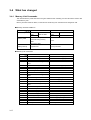
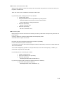
NS-series HMIs
NS12-TS00@-V1, NS12-TS01@-V1
NS10-TV00@-V1, NS10-TV01@-V1
NS8-TV00@-V1, NS8-TV01@-V1
NS5-SQ00@-V1, NS5-SQ01@-V1
Non-PLC Host Connections
CONFIGURATION MANUAL
Notice
OMRON products are manufactured for use according to proper procedures by a
qualified operator and only for the purposes described in this manual.
! DANGER
The following conventions are used to indicate and classify precautions in this manual.
Always heed the information provided with them. Failure to heed precautions can result
in injury to people or damage to property.
Indicates an imminently hazardous situation which, if not avoided, will result in death or
serious injury.
! WARNING Indicates a potentially hazardous situation which, if not avoided, could result in death or
serious injury.
! Caution
Indicates a potentially hazardous situation which, if not avoided, may result in minor or
moderate injury, or property damage.
OMRON Product References
All OMRON products are capitalized in this manual. The word "Unit" is also capitalized when it
refers to an OMRON product, regardless of whether or not it appears in the proper name of
the product.
The abbreviation "Ch," which appears in some displays and on some OMRON products, often
means "word" and is abbreviated "Wd" in documentation in this sense.
The abbreviation "PLC" means Programmable Controller.
The abbreviation “host” means a controller, such as an IBM PC/AT or compatible computer,
that controls a PT (Programmable Terminal).
Visual Aids
The following headings appear in the left column of the manual to help you locate different
types of information.
Note
Indicates information of particular interest for efficient and convenient operation
of the product.
Reference
Indicates supplementary information on related topics that may be of interest to
the user.
1, 2, 3...
1. Indicates lists of one sort or another, such as procedures, checklists, etc.
CS1G-CPU@ @ -VI
Boxes in model numbers indicate variable characters. For example,
"CS1G-CPU@ @ -EV1" indicates the following models: CS1G-CPU42-EV1,
CS1G-CPU43-EV1, CS1G-CPU44-EV1, and CS1G-CPU45-EV1.
Ó OMRON, 2003
All rights reserved. No part of this publication may be reproduced, stored in a retrieval system, or transmitted, in any form, or
by any means, mechanical, electronic, photocopying, recording, or otherwise, without the prior written permission of
OMRON.
No patent liability is assumed with respect to the use of the information contained herein. Moreover, because OMRON is
constantly striving to improve its high-quality products, the information contained in this manual is subject to change without
notice. Every precaution has been taken in the preparation of this manual. Nevertheless, OMRON assumes no responsibility
for errors or omissions. Neither is any liability assumed for damages resulting from the use of the information contained in
this publication.
Contents
Notice ................................................................................................................................. 1
About this Manual ................................................................................................................. 6
Related Manuals ................................................................................................................... 7
Terminology........................................................................................................................... 8
Introduction............................................................................................................................ 9
Section 1 Possible Combinations
1-1List of combinations
1-2NS-Designer and System Program version
Section 2 Connection of Temperature Controller
2-1Outline
2-2Possible combinations
2-3Configuration
2-4Setting projects
2-5Monitor variables area in temperature controller
2-6Operation of temperature controller
2-7Functional restrictions
Section 3 Connection via Memory Link
3-1How does Memory Link work
3-2Setup
3-3Communications procedures
3-4What has been changed since NS31/631
About this Manual
Section 1 Possible Combinations
This section provides information of possible combination of NS-Designer and system program when making
connection with PT and host other than OMRON PLCs.
Section 2 Connection of Temperature Controller
This section provides information on connection methods and communications setting in connecting NS-series PTs
with a Temperature Controller by serial port. It also provides information Temperature Controller which can be
connected to the PT.
Section 3 Connection via Memory Link
This section describes information on connection methods and communication setting in connecting NS-series PTs
with a host by Memory Link.
WARNING Failure to read and understand the information provided in this manual may result in
personal injury or death, damage to the product, or product failure. Please read each
section in its entirety and be sure you understand the information provided in the section
and related sections before attempting any of the procedures or operations given.
6
Related Manuals
The following manuals are used for NS-series PTs. (The boxes at the end of the catalog
numbers indicate the revision code.)
NS Series -V1 Host Connection Manual.....................................V085-E1-@
Provides information on NS Series V1 models (i.e., NS12-V1, NS10-V1, NS8-V1,and
NS5-V1).
Describes how to connect the PT to the host and peripheral devices, methods to setup
communications and operation, and procedures for maintenance.
Refer to the NS Series Programming Manual (V073-E1-@) for information on PT
functions and specific operating procedures.
NS Series -V1 Setup Manual .....................................................V083-E1-@
Provides information on NS Series V1 models (i.e., NS12-V1, NS10-V1, NS8-V1,and
NS5-V1).
Describes how to connect the PT to the host and peripheral devices, methods to setup
communications and operation, and procedures for maintenance.
Refer to the NS Series Programming Manual (V073-E1-@) for information on PT
functions and specific operating procedures.
NS Series Setup Manual……………………………………………..V072-E1-@
Provides information on existing NS Series models (i.e., NS12, NS10, and NS7).
Describes how to connect the PT to the host and peripheral devices, methods to setup
communications and operation, and procedures for maintenance.
Refer to the NS Series Programming Manual (V073-E1-@) for information on PT
functions and specific operating procedures.
NS Series Programming Manual ................................................V073-E1-@
Describes the screen configurations, object functions, and host communications for the
PT.
NS-Designer Operation Manual..................................................V074-E1-@
Describes operating procedures for the NS-Designer, which is used to create the
screens displayed on the PT and transfer them to the PT. It includes screen creation
and transfer procedures.
7
Terminology
The following terminology is used in this manual.
PT
In this manual, indicates an NS-series Programmable Terminal.
NS Series
Indicates products in the OMRON NS@ @ Series of Programmable Terminals.
PLC
Indicates a Programmable Controller in the OMRON SYSMAC CS/CJ, C, or
CVM1/CV Series of Programmable Controllers.
CS/CJ Series
Indicates Programmable Controllers in the OMRON SYSMAC CS/CJ Series of
Programmable Controllers: CS1G, CS1H, CS1G-H, CS1H-H, CJ1G, CJ1M.
C Series
Indicates products in the OMRON SYSMAC C Series of Programmable
Controllers: C200HS, C200HX(-Z), C200HG(-Z), C200HE(-Z), CQM1, CQM1H,
CPM1A, CPM2A, CPM2C.
CVM1/CV Series
Indicates products in the OMRON SYSMAC CVM1/ CV Series of Programmable
Controllers: CV500, CV1000, CV2000, CVM1
Serial Communications Unit
Indicates a Serial Communications Unit for an OMRON CS/CJ-series PLC.
Serial Communications Board Indicates a Serial Communications Board for an OMRON CS-series or CQM1H
PLC.
8
Communications Board
Indicates a Communications Board for an OMRON C200HX/HG/HE(-Z) PLC.
CPU Unit
Indicates a CPU Unit in the OMRON SYSMAC CS/CJ, C, or CVM1/CV Series of
Programmable Controllers.
NS-Designer
Indicates the OMRON NS-Designer (NS-NSDC1-V@ ).
Host
Indicates the PLC, IBM PC/AT or compatible computer, or personal computer
functioning as the control device and interfaced with the NS-series PT.
Programming Manual
Indicates the NS Series Programming Manual (V073-E1-@).
Introduction
· Intended Audience
This manual is intended for the following personnel, who must also have knowledge of
electrical systems (an electrical engineer or the equivalent).
· Personnel in charge of introducing FA systems into production facilities.
· Personnel in charge of designing FA systems.
· Personnel in charge of installing and connecting FA systems.
· Personnel in charge of managing FA systems and facilities.
· General Precautions
· The user must operate the product according to the performance specifications
described in the operation manuals.
· Do not use the PT touch switch input functions for applications where danger to human
life or serious property damage is possible, or for emergency switch applications.
· Before using the product under conditions which are not described in the manual or
applying the product to nuclear control systems, railroad systems, aviation systems,
vehicles, combustion systems, medical equipment, amusement machines, safety
equipment, and other systems, machines and equipment that may have a serious
influence on lives and property if used improperly, consult your OMRON representative.
· Make sure that the ratings and performance characteristics of the product are sufficient
for the systems, machines, and equipment, and be sure to provide the systems,
machines, and equipment with double safety mechanisms.
· This manual provides information for connecting and setting up an NS-series PT. Be
sure to read this manual before attempting to use the PT and keep this manual close at
hand for reference during installation and operation.
· Safety Precautions
Do not attempt to take the Unit apart and do not
touch any internal parts while the power is being
supplied. Doing either of these may result in
electrical shock.
· Operating Environment Precautions
1. Do not install the Unit in the following places:
· Locations subject to direct sunlight
· Locations subject to temperatures or humidity outside the range specified in the
specifications
· Locations subject to condensation as the result of severe changes in temperature
· Locations subject to corrosive or flammable gases
· Locations subject to dust (especially iron dust) or salts
· Locations subject to exposure to water, oil, or chemicals
9
· Locations subject to shock or vibration
2. Take appropriate and sufficient countermeasures when installing systems in the following
locations:
· Locations subject to static electricity or other forms of noise
· Locations subject to strong electromagnetic fields
· Locations subject to possible exposure to radioactivity
· Locations close to power supplies
· Application Precautions
1. When unpacking the Units, check carefully for any external scratches or other damage.
Also, shake the Units gently and check for any abnormal sound.
2. The mounting panel must be between 1.6 and 4.8 mm thick. Tighten the Mounting
Brackets evenly to a torque of between 0.5 and 0.6 N×m to maintain water and dust
resistance. Make sure the panel is not dirty or warped and that it is strong enough to hold
the Units.
3. Do not let metal particles enter the Units when preparing the panel.
4. If conformance to EC Directives (Low Voltage Directive) is required, use reinforced
insulation for the power supplies.
5. Do not connect an AC power supply to the power terminals.
6. Use a DC power supply with minimal fluctuation voltage.
Rated power supply voltage: 24 VDC
(Allowable range: 20.4 to 27.6 VDC)
Capacity: 25 W min. (NTLP:INFORMATION MISSING IN JAPANESE NS5: ???W min.)
7. Do not perform a dielectric voltage test.
2
8. Use a twisted-pair cable with a cross-sectional area of at least 2 mm to connect to the
power terminals and always use M3.5 crimp terminals. Tighten the terminal screws to a
torque of 0.8 N×m. Make sure the screws are properly tightened.
9. Ground the Unit correctly to prevent operational errors caused by noise.
10. Do not touch the surface of the circuit board or the components mounted on it with your
bare hands. Discharge any static electricity from your body before handling the board.
11. Confirm that the current capacity of the connected device is 250 mA or less before using
the 5-V power supply from pin 6 of the serial port A, B connectors. The 5-V output of the
PT is 250 mA max. at 5 V ±5%.
12. Turn OFF the power supply before connecting or disconnecting cables.
13. Always tighten the connector screws after connecting communications cables.
14. The maximum tensile load for cables is 30 N. Do not apply loads greater than this.
15. Confirm the safety of the system before turning ON or OFF the power supply or before
pressing the reset button.
16. The whole system may stop depending on how the power supply is turned ON or OFF.
Turn ON or OFF the power supply according to the specified procedure.
17. Start actual system application only after sufficiently checking screen data. macros, and
the operation of the program in the PC (host).
18. Always reset the power supply after changing switch settings.
19. After changing the settings of the DIP switch, always turn the power supply OFF and ON
or reset the PT.
20. Do not perform the following operations while the Memory Card is being accessed:
· Turning OFF the power supply to the PT
· Pressing the PT’s reset switch
· Removing the Memory Card
Always following the specified procedure when removing the Memory Card.
21. Do not press the touch switch with a force greater than 30 N.
10
22. Confirm the safety of the system before pressing touch switches.
23. Do not accidentally press touch switches when the backlight is not lit or when the display
does not appear.
24. Signals from the touch switches may not be input if the switches are pressed
consecutively at high speed. Confirm each input before proceeding to the next one.
25. Before initializing screen data, confirm that existing data is backed up at the NS-Designer.
26. When changing the password with the system menu, do not reset or turn OFF the power
supply until writing is finished (i.e., until the Write Button returns to its original condition). It
may become impossible to manipulate screens if the password is not set correctly.
27. When using the device monitor, confirm the safety of the system before performing the
following operations.
· Changing monitor data
· Changing operation modes
· Forced setting or resetting
· Changing present values or set values
28. Do not use benzene, paint thinner, or other volatile solvents, and do not use chemically
treated cloths.
29. Dispose of any battery that has been dropped on the floor or otherwise subjected to
excessive shock.
30. Do not attempt to disassemble, repair, or modify the Unit in any way.
31. Dispose of the Units and batteries according to local ordinances as they apply.
32. To ensure system safety, incorporate a program that periodically calls PT operation bits
from the host side to check that the PT is properly operating.
33. Do not connect an USB connector to any device that is not applicable.
34. Before connecting an USB connector to a device, make sure that the device is free of
damage.
35. When mounting the Battery, be sure to use the correct Battery and mount it correctly.
11
Section 1
Possible combinations
This section explains in general how to connect hosts other than NS-V1 Series Omron PLC
and which models to connect.
1-1List of combinations
1-2NS-Designer and System Program version
1-1 List of combinations
This explains the configuration when host is other than Omron PLCs.
1-1-1 Connection of temperature controller
Communicates with Omron temperature controller via RS-485.
Connect RS-422 converter CJ1W-CIF11 to serial port A or B and set communication mode to RS-485.
For details, refer to ‘Chapter 2: connection of temperature controller’.
1-1-2 Connection with memory link
When host other than PLC such as board-controller and personal computer is used, connection via
memory link is possible. Use serial port A or B to connect host equipment. For details, refer to ‘chapter
3: connection via memory link’.
1-1
1-2 NS-Designer and System Program versions
1-2-1 NS-Designer versions
With NS-Designer Ver.5.0 or later version, you can create and edit projects for Temperature Controller
connections and Memory Link connections.
1-2-2 System Program versions
System program Ver.5.0 or later.
A copy of this version is included NS-Designer Ver.5.0.
NS with -V1 suffix models (NS12/10/8/5 –V1) are supported for those connections.
NS without –V1 suffix models are not supported.
When system program version is earlier than Ver.5.0, you need to upgrade. For details on how to upgrade,
refer to the manual (PDF)(Recover NS Ver.5) in NS-Designer.
1-2
Section 2
Connection of temperature controller
This section explains how to connect Omron temperature controllers (E5@N) and digital
controllers (E5AR/ER) and which models to connect.
2-1Outline
2-2Possible combinations
2-3Configuration
2-4Setting projects
2-5Monitor variables area in temperature controller
2-6Operation of temperature controller
2-7Functional restrictions
2-1 Outline
This explains how to connect temperature controllers.
Connectable are temperature controllers with a RS-485 port.
Use NS serial port A or B (either one), use converter to transform to RS-485.
1 serial port can accommodate max. 31 temperature controllers.
Temp.
controller
NS-series PT
Temp.
controller
Serial port A or B
converter
CJ1W-CIF11
RS-485
(max.
extension:50m)
By using another communications port, you can simultaneously connect temperature controllers and a host. With
one more serial port, NS can connect PLC, barcode reader, Memory Link and can communicate with
NS-Designer.
If NS is equipped with Ethernet port, communications with Omron PLC via Ethernet is possible.
If equipped with Controller Link I/F, communication with Omron PLC via Controller Link is possible.
2-1
2-2 Possible combinations
2-2-1 Connectable temperature controller
Only models with RS-485 communications port that support CompoWay/F can be used.
The following models are connectable:
Name
Temperature
controller
Digital
temperature
controller
Series
Model
E5ZN
E5AN
E5ZN-SCT24S (terminal unit)
E5AN- @ @ @ 03 @ -FLK
E5EN
E5EN- @ @ @ 03 @ -FLK
E5CN
E5CN- @ @ @ 03 @ -FLK
E5GN
E5GN- @ @ @ 03 @ -FLK
E5AR
E5AR-QC43DB-FLK
E5AR-QQ43DW-FLK
E5AR-CC43DWW-FLK
E5ER-QC43B-FLK
E5ER-PRQ43F-FLK
E5ER-QT3DW-FLK
E5ER-CT3DW-FLK
E5ER
2-2-2 Temperature controller Manuals
Manual name
Catalog No.
E5CN/CN-U User’s manual
E5GN User’s manual
E5 L N User’s manual Communications functions
E5EN User’s manual
E5AN User’s manual
E5AR/ER User’s manual
H100-E1
H101-E1
H102-E1
H111-E1
H112-E1
Z182-E1
2-2
2-3 Configurations
2-3-1 Necessary parts
■ RS-422A Converter
CJ1W-CIF11
■ Crimp terminal
● CJ1W-CIF11side
communications path terminator
Phoenix Contact
AI Series
AI-0.5-8WH-B
ZA3
Crimp tool
● CJ1W-CIF11 side
Phoenix Contact
Crimp tool
E5CN
E5GN
E5EN
E5AN
E5ZN
E5ER/AR
2-3
(serial No. 1201882)
other than communications path terminator
AI series
AI-TWIN2×0.5-8WH
UD6
● Temperature controller side
Model
(serial No. 3201369)
Terminal block
screw size
Terminal size
M3.5
7.2mm max.
M3
5.8mm max.
(serial No. 3200933)
(serial No. 1204436)
2-3-2 Wiring diagram
NS side
Temperature controller side
E5AN
E5ZN E5EN E5GN E5ER
E5CN
CJ1W-CIF11
terminal
E5AR
Terminal number
SDB(+)
B(+)
23
11
5
C1
F1
SDA(-)
A(+)
24
12
6
C2
F2
FG
To next temperature
controller
■ Connection: 1:1 or 1:N. If 1:N, max. 32 units (NS and temperature controllers combined) can be connected.
(in case of E5ZN, the maximum is 16 units).
■ Cable length: In total max. 50 m
■ Use shielded twist pair cables (min. size AWG28)
■ Connect terminating resistance (100 to 125Ώ(1/2W) to both ends of the communications path.
Furthermore,
combined resistance must be 54 Ώ min.
2-4
2-3-3
Temperature controller communications settings
This summarizes temperature controller communications settings.
For more details on settings and operation procedure of setting specifications, refer to the relevant temperature
controller manual.
■ E5ZN
Setup Switch on E5ZN panel
Unit number
When using multiple E5ZN units, be
careful not the use the same number
twice.
4800 Bps
9600 Bps
19200 Bps
0 to 15
Baud rate
0
1
2
Communications setting level
Data bits
Stop bits
Parity
Response
Waiting time
C3
C3
C3
C3
C3
C3
C3
C3
CH
0013 or
0113
0014 or
0114
0015 or
0115
0016 or
0116
Value
7
7 bits
2
2 bits
2
Even (EvEn)
0 to 270FH
( 0 to 9999)
In ms
■ E5GN/E5AN/E5EN/E5CN/E5ER/E5AR
Adjustment level L.Adj
Communications CoWt
writing
Communications setting level L.S
Baud rate
bPS
on
OFF
enable
disable
2.4
4.8
In kbps
Set all communicating temperature
controllers to match parameters of NS
E5ER/AR: choose between
9.6/19.2/38.4
E5@N: 38.4 cannot be selected.
7 bits
2 bits
Even
In ms
E5AR/ER range: 0 to 63H(0 to 99)
9.6
19.2
38.4
2-5
Data bits
Stop bits
Parity
Response
Waiting time
LEn
Sbit
Prty
SdWt
Communications
Unit No.
Protocol select
U-no
7
2
EvEn
0 to 270FH
( 0 to
9999 )
0 to 31
PSEL
CyF
E5AR/ER only
Compoway/F (E5AR/ER only)
2-3-4
CJ1W-CIF11 setting
Dip switch setting
Pin No.
Function
Terminal resistance
select ON/OFF
1
Switch between
system
Switch between
system
Not used
RD control by RS
select ON/OFF
SD control by RS
Select ON/OFF
2
3
4
5
6
2-3-5
setting
ON
OFF
2/4
line
ON
2/4
line
ON
Terminating resistance (on both
ends of the communications path)
No terminating resistance (other
than both ends of the
communications path)
2 line system
OFF
ON
RS control function ON
NS setting
Before you can connect temperature controllers, you need to store the required project in the NS. For project
setting, refer to ‘2-4 project setting’.
With communications settings under system menu, you can set the speed of
communications.
Baud rate
2400 / 4800 / 9600 / 19200 / 38400 / 57600 /115200
Of these values,
bps
57600 / 115200 are for future use.
Present temperature controllers cannot operate at these rates.
Set PT unit and temperature controller baud rate values to match each other.
2-6
2-4
Setting Project
With this function, you set projects needed to connect temperature controllers.
Select Setting - System Setting. System Setting dialogue opens.
Select tab Comm - All.
Select Temperature Controller from the pull down menu for Serial Port A ( or Serial B).
2-7
Select tab Serial Port A (or Serial Port B) and set baud rate.
Selectable baud rate values are:
2400 / 4800 / 9600 / 19200 / 38400 / 57600 / 115200 (in bps).
Baud rates 57600 / 115200 are for future use. Present temperature controllers cannot operate at these rates.
2-8
Next, click Settings - Register Host. Host Registration Dialogue opens. Define temperature controller model to be
connected.
2-9
2-5
Monitor variables area in temperature controller
2-5-1
Variables area in temperature controller
Data stored in variable area of the temperature controller are: Present Value, SP, Heater burnout alarm status and
such.
By reading/writing these data from PT, you can monitor temperature controller status.
Values of variables you can display on PT screen as numbers and you can create save the changes of those as
log data.
Temperature controller status (variable C0, address 0001) is information on bit level. You can show status by
ON/OFF lamp and you can display/save the history log that shows status changes.
Address of variable are in a Temperature Controller should be assigned to the lamps, numeral display and input
object, or graphs before monitoring the variable area.
Accessible address ranges vary with temperature controller models.
For details on accessible address ranges and definitions of settable address ranges, numerical values and contact
status, refer to the following manuals.
Model
Manual
Number
Chapter
E5AN
E5EN
E5CN
H102-E1
3
E5GN
E5ZN
H112-E1
5, 5.10 Variables area map
E5AR
E5ER
Z182-E1
Appendix Settings list
NS-Designer shows accessible address range in accordance with the model specified in the Register Host dialog
so that user can set an appropriate communication address.
2-10
You can also manually enter a communications address, which is not listed without opening Address Setting dialog.
In this case, enter the desired address directly to the field shown in the property dialog.
2-11
2-5-2
Address notation in NS-Designer
Address notation when accessed using word
communications)
<port>
:
<Communications #
unit No..>
<Variable
category>
(address for word
<Channel>
<Address>
Address when accessed using bit (address for bit communications)
<port>
:
<communications #
unit No.>
<Variable
category>
Item
<Port>
<communications
unit No. >
<Variable type>
<Channel>
<Address>
<Pit position>
<channel>
<address>
.
<bit
position>
Value range & definition
SerialA
SerialB
00 to 31
Connected to serial port A
Connected to serial port B
C0 to D7
00 to 03
ch1 to ch4
variable
category
C0 to C3
C4 to CB
CC to D7
00
to
Address range
00 to 3F
00 to 7F
00 to 3F
31
Example:
SerialA:24#C4001C
SerialB:17#D1036E.
3
2-5-3
PortA:Unit No.24/area category C4/ch1/address 1CH
PortB:Unit No.17/area D1/ch4/address6EH/bit3
Use of double word numbers
Variable area in the Temperature Controller is composed of values in double-word format(32bit length).
Negative values are expressed as the two’s complement. Therefore, select DINT(signed 2 words) as
storage type for the variable, which the decimal value will be stored. Select UDINT(unsigned 2 words) for
the variable, which the hexadecimal value will be stored.
2-5-4
Communications writing enabled/disabled
Before you can write to variable area in temperature controller, you need to go to the adjustment level
and set Communications writing on Enabled: ON. (Default setting is Disabled: OFF).
For monitoring only, so when no writing is carried out, the setting can be either Disabled: OFF or
Enabled: ON.
Use either the panel on the Temperature Controller or Setting Tool to set “Communications Writing”
parameter. It can be also set with Smart Active Parts in the PT.
2-12
2-6
Operation of Temperature Controller
The use of Smart Active Parts, allows you to operate PT screen to change Temperature Controller running
conditions and to disable/enable communications writing.
2-6-1
How to create a Smart Active Parts part
In NS-Designer, you open the arrange Smart Active Parts screen.
When you select Tools - Use Library , the library dialogue opens.
Under list of categories, tree of selectable libraries is shown.
Smart Active Parts for temperature controller you can find under PartsLib -> Smart Active Parts ->
Temperature Controller.
Temperature controller is grouped by model, channel and broadcast. For each operation instruction, a Smart Active
Parts part is available.
There are 2 categories: Instructions to the unit itself and broadcast .
When same instruction is given to all units, no results response is sent. For that reason error judgment is omitted.
Selectable Smart Active Parts are shown in the preview box on the right. Title of the selected Smart
Active Parts
are shown in the bottom center dialogue box.
Select appropriate Smart Active Parts and click Use.
By doing so, the selected Smart Active Parts is pasted onto the screen that is being edited.
The Smart Active Parts part is pasted onto the upper left corner of the screen. Move to the desired location.
Or, click the Smart Active Parts part and set communications parameters.
port to which command SerialA
is sent
SerialB
Destination Unit No.
0 to
31
:when connected to serial port A
:when connected to serial port B
:Communications unit No. of the
temperature
controller you want to operate.
With broadcast to all parts, this parameter
is not used. Keep default value 0.
2-13
When you want to change the label and color setting of the Smart Active Parts, go to Tools – Options – Edit/Disp
tab and check the Edit Smart Active Parts properties. Double click on the desired object to open the property
dialog and the settings can be changed.
Do not change the communications address when editing the settings. Once it has been changed, the Smart Active
Parts will not function properly anymore.
Furthermore, once you have selected certain options, you cannot set Smart Active Parts communications settings
anymore. So when you want to modify the communications settings, deselected options.
2-14
2-6-2
Smart Active Parts Operations
Smart Active Parts for Temperature Controllers are grouped by Temperature Controller model, channel, instruction
to single unit/broadcast, control details.
Smart Active Parts title indicates the operating instruction to be executed.
■Communications writing enabled/disabled
You can either enable or disable the writing of set values from communications.
When communications writing is disabled, the writing of set values from communications and the execution of
certain instructions is prohibited.
Default setting is set as Disable.
By executing Smart Active Parts Enable communications writing/Disable communications writing, you
can switch between enabled/disabled.
If communications writing is not enabled before writing set values with numeral display & input object or word
button, an error occurs.
Furthermore, by disabling communications writing, you can avoid that set values are being changed by
accident.
A summary of executable/non executable instructions when communications writing is disabled, is given in
table ‘2-6-3 Smart Active Parts list’.
■Setting area 0/setting area 1
Temperature controller communications has 2 operation modes: setting area 0 and setting area 1.
In setting area 0, control operations are conducted. You cannot modify any set values that negatively affect
the control operations. When power supply is turned on, this mode is selected.
In Setting area 1, the control operations are stopped. You can modify the set values protected in Setting area
0.
You can switch to Setting area 1 by executing Smart Active Parts part ‘Move to setting area 1’.
To change from Setting area 1 to Setting area 0, you can either turn the power off and then back ON again or
you can execute Smart Active Parts part: “ Software Reset”.
Executable operating instructions vary depending on which mode is selected: setting area 0 or 1.
Non executable in setting
Area 0
Initialize set values
2-15
Non executable in setting
Area 1
AT execute/cancel
Move to protect level
Auto/manual
PV hold
■Confirm command results
Under certain conditions e.g. communications writing disabled, it can happen that a selected Smart Active
Parts instruction cannot be executed.
But, when performing the broadcast, no response is given. In that case there is no check as to whether the
action was completed successfully or not.
Theref,ore adopt a method that checks if the operation was carried out properly, e.g. lamp indication.
Title
(operating instruction)
Model
Common
E5ZN
E5@R
Communications writing
disabled
Communications writing
enabled
run
stop
AT execute
AT cancel
Writing mode: back-up
Writing mode: RAM
Move to setup area 1
auto
manual
Cancel alarm 1 latch
Cancel alarm 2 latch
Cancel alarm 3 latch
Cancel all alarm latches
Cancel alarm latch
SP mode: local SP
SP mode: remote SP
Select bank: 0 to 7
AT execute
(confirm executing PID
group No.)
*1
Addresses to be monitored
ch1
CO0001.25
ch 2
CO 0101.25
ch1
ch 2
ch1
ch 2
ch1
ch 2
ch1
ch 2
ch1
ch2
ch1
ch2
CO 0001.24
CO 0101.24
CO 0001.23
CO 0101.23
CO 0001.20
CO 0101.20
CO 0001.22
CO 0101.22
CO 0001.26
CO 0101.26
C00001.12 to 15
C00101.12 to 15
*1
ch1
ch 2
ch 3
ch 4
*1
ch1
ch 2
ch 1
ch 2
ch 3
ch 4
ch 1
ch 2
ch 3
ch4
C00001.12 to 15
C00101.12 to 15
C00201.12 to 15
C00301.12 to 15
C00001.27
C00101.27
C40408
C41408
C42408
C43408
C4040A
C4140A
C4240A
C4340A
Confirm that alarm output has become OFF.
Attention: Under certain conditions such as PV that an alarm
might be output, you cannot confirm because alarm output
remains high even when the latch is cancelled
2-16
2-6-3
List of Smart Active Parts
For broadcast and for single unit commands respectively.
Model
CH
E5@N
Common
Title
(operating instruction)
Communications writing
disabled
Communications writing
Enabled
Run
stop
Multi SP: select target Value 0
Multi SP: select target value 1
Multi SP: select target value 2
Multi SP: select target value 3
AT execution
AT cancel
Writing mode: back up
Writing mode: RAM
Save RAM data
E5ZN
Common
Reset soft
Move to setup area 1
Move to protect level
Communications writing
disabled
Communications writing
enabled
Writing mode: back up
Writing mode: RAM
Save RAM data
Outline
*1
switch between Communications writing
Enabled/disabled.
Start control (run).
Stop control (stop).
Switch between multi SP target values
OK
Execute/cancel AT
Select whether or not to write
operation/adjustment settings to internal
non-volatile memory when writing from
communications
Write operation/ adjustment level settings to
internal non-volatile memory.
Reset software
Move to settings area 1
Move to protect level
Switch between communications writing
enabled/disabled.
NG
OK
Select whether or not to write
operation/ adjustment level settings to
internal non-volatile memory when writing
from communications
Write operation/ adjustment level settings to
internal non-volatile memory.
Reset soft。
Move to settings area 1
Move to protect level
Save Present value at time of execution.
Set parameters to default values
Start control (run)
Stop control (stop)
Switch between multi SP target values
Reset soft
Move to setup area 1
Move to protect level
PV hold
Initialize parameters
CH1/
Run
CH2/
stop
All CH
Multi SP: select target Value 0
Multi SP: select target Value 1
AT execute
Execute AT
AT cancel
Cancel AT
auto
Switch between auto-operation/manual
operation
manual
Cancel alarm latch
Cancel alarm 1 latch
Cancel alarm 2 latch
Cancel alarm 3 latch
Cancel all alarm latches
*1:cannot be executed when communications writing is disabled.
NG
OK
NG
When you execute an operating instruction designated to all channels, models other than the analog output type
E5ZN do not operate properly.
2-17
Model
E5@R
CH
Common
Title
(operating instruction)
communications writing
disabled
Communications writing
enabled
Writing mode: back up
Writing mode: RAM
Save RAM data
outline
Switch between communications writing
enabled/disabled
*1
OK
Select whether or not to write
operation/adjustment level settings to
internal non-volatile memory when writing
from communications
Write operation/adjustment level settings to
internal non-volatile memory.
Reset soft
Move to setup area 1
Move to protect level
Set parameters to default values
Start control (run)
Stop control (stop)
Switch setting bank of target value, alarm
value, PID group No. setup bank
Reset soft
Move to setup area 1
Move to protect level
Initialize parameters
CH1/
Run
CH2/
Stop
CH3/
Switch bank 0
CH4/
Bank Switch 1
All CH
Bank Switch 2
Bank Switch 3
Bank switch 4
Bank switch 5
Bank switch 6
Bank switch 7
AT execution:selected PID
Execute AT with presently selected PID or
with designated PID group No. PID.
AT execution: PID 1
AT execution: PID 2
AT execution: PID 3
AT execution: PID 4
AT execution: PID 5
AT execution: PID 6
AT execution: PID 7
At execution: PID 8
At cancel
Cancel AT
Select between Auto-operation/manual
Auto
operation
manual
Cancel alarm latch
Cancel alarm latch
CH1/
Select SP mode (local SP/remote SP).
SP mode: local SP
CH2
SP mode: remote SP
*1:cannot be executed when communications writing is disabled.
NG
OK
NG
When you execute an operating instruction designated to all channels, models other than the analog output type
E5ZN do not operate properly.
2-18
2-7
Restrictions
2-7-1
The behavior of 2 word number in the NS-Designer test function
In the temperature controller, a value equivalent to 2 words (32 bits) is stored for each communications address,
but in the test function, the first 16 bits and the last 16 bits behave as one and the same value. For that reason, test
function will not operate successfully when 2 word numbers are designated.
2-7-2
Address display when address error occurs
When faulty device is set to communications address set in functional object, this communications address is
displayed in the device setting error dialogue.
If the communications address is allocated to the temperature controller, not the address for the temperature
controller set with the NS-Designer, but the address in the PLC address format is displayed. Addresses will be
converted as shown below.
Address displayed when faulty device is set to communications address
<Device>
3
2
1
0
15 14 13
0
12
Ch
0-3
Unit No.
0 to 31
11 10
0000 to 7FFF
00 to 15
Word address
Bit position
9
<variable>
0 to F
8
7
6
5
4
3
2
1
<address>
0000 to 007F
0
7
6
5
4
0
0
0
0
3
2
Bit position
0 to 31
CH address of temperature controller
Unit
No.
<Device>
<Variable >
Temp
controller
0
1
2
3
4
5
6
7
8
9
A
B
C
D
E
F
C0
C1
C2
C3
C4
C5
C6
C7
C8
C9
CA
CB
CC CD
CE CF
D0
D1
D2
D3
D4
D5
D6
D7
<Address>
Variable
DM
EM
EM0_
EM1_
EM2_
EM3_
EM4_
EM5_
EM6_
EM7_
EM8_
EM9_
EMA_
EMB_
EMC_
WR
2-19
0
2
4
6
8
10
12
14
16
18
20
22
24
26
28
30
1
3
5
7
9
11
13
15
17
19
21
23
25
27
29
31
0000 to 003F
0040 to 007F
0000 to 007F
0040 to 007F
0000 to 003F
0040 to 007F
0000 to 003F
0040 to 007F
0000 to 003F
1
0
Device setting errors are not likely to occur. This because, setting is done using the method by which a selection is
made from a list of accessible addresses for each temperature controller model.
However, in below cases in which the address is not selected from the list of accessible addresses an invalid
address may have been assigned. In such a case, a device setting error may occur.
l
Communications address set when functional object was copied using repeat command when
index was assigned.
l
Communications address set by ‘Allocate Addresses Automatically ’ in the frame property.
l
Communications address set by using the macro function.
Furthermore,
l
Writing to read-only area
l
Writing while communications writing was prohibited
cause device setting errors to occur.
2-7-3
Communications address set when functional part was copied
using repeat command
In NS-Designer, you can select functional object and when you then execute ‘repeat’ , you can copy while
communications addresses are being added.
The temperature controller’s address is a double word address. To increment a double word address by 1, you
need to increment a single word address by 2.
Address in NS-Designer is expressed as a 1 word address. When repeat command is used to copy functional
object, 1 word is added to 1 word address.
For that reason, when communications address offset width is 1 while repeat command is used, part with the same
communications address is copied twice.
Actual address
Internal address
Double word
+0
Single word
+0
+0
+1
+1
+1
+2
+3
(0.5)
(1.5)
Address originally set for functional
object
Omit figures below decimal0.5->0
Omit figures below decimal 0.5->0
For that reason, set always offset in multiples of 2 to specify communications address with single
word access.
2-20
Section 3
Connection via Memory Link
This chapter explains the Memory Link function and how to use it to connect host computer.
3-1How does Memory Link work
3-2Setup
3-3Communications procedures
3-4What has been changed since NS31/631
3-1
How does Memory Link work
3-1-1
PT memory
With Memory Link you assign objects word and bit to PT memory.
PT memory is an imaginary PLC area inside
the NS. NS performs read/write operations to internal PT memory. Host reads/writes PT memory as required
and so controls and monitors NS.
PT memory consists of 2 territories: Bit ($B) and Word ($W).
PT memory can be also used to store functional object display character strings or as data area for the macro
function.
3-1-2
Command and response
With Memory Link, the following commands enable data transmission between host and PT.
- Read-out command / response
This is the command for reading out PT memory of PT.
When host gives command, PT responds the contents of the designated data.
There are 2 commands that vary with the type of PT memory.
Command
Title
Action
RM
RB
Read out PT ($W) memory
Read out PT ($B) memory
Read out $W data in PT memory
Read out $B data in PT memory
- Write command/response
This is the command to write designated data to PT memory area in PT.
Host gives command. PT responds whether or not the writing was completed successfully.
The successful completion response may be omitted by particular setting the Response parameter in the
communications conditions menu.
The following 4 commands can be given:
Command
Title
Action
WM
WB
FM
Write to PT memory ($W)
Write to PT memory ($B)
FILL PT memory ($W)
FB
FILL PT memory ($B)
Write data to PT memory $W
Write data to PT memory $B
Write designated data to multiple
PT memory $W
Write designated data (0 or 1) to
Multiple PT memory $B.
- Notify Command
This is the command to communicate the results of PT operations to host.
PT gives command. For that reason, there is no response.
The following 2 commands can be given.
3-1
command
Title
Action
SM
SB
PT memory ($W) change notice
PT memory ($B) change notice
Notify host of PT memory $W changes.
Notify host of PT memory $B changes.
- Error response
Response from PT when the received command is an invalid one.
3-1-3
Command
Title
Action
ER
Error response
Notify host of command error
Action when command is used
There are 3 flows of communications between host and PT, depending on the type of command and Response
Settings in Communications conditions.
- Write data command while [response: OFF]
[Host]
Send command
Write data command
[PT]
Receive command
Process command
- Write Data command while [response: ON]
- Read-out data command
- Invalid command
[Host]
command
Send command
[PT]
Receive command
Process command
receive response
Send response
- PT to host communications
[Host]
[PT]
PT operation
Change PT memory
Receive change
notice command.
Communicate command
Send change notice
command
3-2
3-1-4
Notify Command Behavior
When anything has changed in the PT memory, by e.g. touch switch operation on PT, numerical input or
character string input, PT sends change notice command to host.
In addition to Memory Link connection, PT memory serves other purposes as well. If all changes would be
communicated to host, the host would be burdened more than is needed. For that reason, PT communicates
only changes from a designated number and up. Changes in PT memory areas with a lower number are not
communicated.
Set the number in Communications conditions -> Start Communication $B and Start Communication &W.
$W
$W0
PT
operation
no notice
Number
input
Notice start $W
notify command
Number
input
Only changes from specified $W number and up
are communicated to host using the
change notice Command.
3-1-4
Flow control
When too many commands are sent, PT cannot process timely. Communications buffer overflows. Commands
and command sequence get lost.
For that reason, set Communications conditions Response to ON when PT to host command interval frequency
becomes high.
3-3
3-2
Settings
3-2-1
Making settings for the Project
The Memory Link can be used in combination with
NS system program Ver. 5.0 and later versions
System Ver.5.0 projects
With NS-Designer V5.0 and later, you can create and edit project developed by System Ver.5.0 projects.
A project created with NS-Designer Ver. 4.0 or earlier can be opened and converted to the data of Ver.5.0.
In NS-Designer Ver. 5.0 open SystemVer.5.0 project, click Settings – System Setting. Select tab ‘Comm.– All’
and set Serial Port A (or Serial Port B) to Memory Link (select from the pull down menu).
You cannot simultaneously set Serial Port A and B to Memory Link.
3-4
3-2-2
Communications conditions setting
In NS-Designer, select tab ‘Comm.-All’ Serial Port A (or Serial Port B) and set to the following communications
conditions.
Parameter
3-2-3
Set value
Baud rate
Data bits
9600bps / 19200bps / 38400bps
7/8
Stop bits
Parity
response
Notice start $B
Notice start $W
1/2
None / even / odd
OFF / ON
0 to 32767
0 to 32767
Default value
9600bps
7
1
none
OFF
16384
16384
NS system menu operation
You can also use the NS system menu to set the communications conditions for
the Memory Link connection.
Under system menu, click tab Communications Setting.
By pressing the key beside the Serial Port A or Serial Port B, you can switch between communications methods.
unused
↓
NT Link 1:1
↓
NT Link 1:N
↓
Bar code reader
↓
Temperature controller
↓
Memory Link
After you have thus set communications to Memory Link, use the Details key to set the communications
conditions for the Memory Link connection (for details, refer to section 2.2). However, with system menu you
cannot set the Notice start $B and Notice start $W.
Set values are not saved until you press the Write key. Also, setting changes will be effective when you turn the
power OFF and then ON again.
3-5
3-2-4
Connection Diagram
Use either NS Serial Port A or B to connect host computer via Memory Link.
You cannot simultaneously set Serial Port A and B to Memory Link.
The connecting cable varies with the specifications of the host computer communications port.
Below is a typical example, which shows the wiring diagram when DOS/V PC is connected.
9pin
Dsub(Female)
9pin
Dsub(Male)
3
SD
SD
2
2
RD
RD
3
7
RS
RS
4
8
CS
CS
5
5
SG
SG
9
DOS/V PC
NS-series PT
Above wiring is identical with the NS to and from NS-Designer wiring.
If the cable length is conform, you can use the following cable with connector.
XW2Z-S002
Omron product
Cable length 2m, 9 pinÛ9 pin
3-6
3-3
Communications procedures
3-3-1
Memory Link Commands
Command/response formats are as mentioned below.
·
Read/write/change notify command
ESC
·
*D
SUM
CR
command
*S
*A
*D
SUM
CR
command
*S
*A
*B
*D
SUM
CR
command
*A
*L
*D
SUM
CR
Other responses
ESC
command
*D
ESC
($1B)
command
2 characters
*S
1 character
*A
*B
*L
*D
3-7
*L
Read type command normal completion response format
ESC
·
*A
Write all (FILL) command
ESC
·
*S
Read/write command (In above-mentioned format, the *L is regarded as 1 (fixed))
ESC
·
command
Hexadecimal
4 digits
Hexadecimal
4 digits
BCD 2 digits
Variable length
SUM
2 characters
(may be
abbreviated)
CR
($0D)
SUM
CR
Initial Command: ESC($1B) fixed
1 English capital letters which display the
type of command
Designates SUM omission and *L omission. In some
cases, specifies write to memory attributes as well.
SUM OFF: SUM computing by host can be omitted.
SUM ON: enables judgment if command is invalid as a
result of noise interference.
Initial read/write address
Last Write all (FILL) address
Number of read/write elements
Data section
The checksum of the command response is the 2 digit
code in hexadecimal which is indicated using lower
one-byte of the total sum from the ESC to the *D. It
can be abbreviated by specifying *S. Be sure that it is
added when PT is transmitting.
Command end: CR($0D) fixed
Memory Link commands are as follows:
Command
Command title
Action
RM
RB
WM
WB
Read PT memory ($W)
Read PT memory ($B)
Write PT memory ($W)
Write PT memory ($B)
Fill PT memory ($W)
Read contents of $W data
Read contents of $B data
Write to $W data
Write to $B data
Fill multiple sequential $W with the
same value
Fill multiple sequential $B with the
same value.
Communicate $W changes to host
Communicate $B changes to host
FM
FB
SM
SB
Fill PT memory ($B)
PT memory ($W) change notice
PT memory ($B) change notice
3-8
RM
Read PT memory ($W)
Read $W data in PT memory.
Per command, a maximum of 100 words can be read.
Response is up to 50 words per response.
When requesting command is parameter 2: number of words exceeds 51, then the response is split into two. The
first response sends 50 words, the second response sends the remaining channels.
When entries were made on NS in between the first and second response, change notice command is not sent
until after the second response has been sent.
·
Command format
ESC command
$1B
R
*S
*A
*L
SUM
M
CR
$0D
[Settings]
*S
Sum value
0
1
8
8
0000
7FFF
00 to 99
*A
*L
·
Number of read-out words (BCD 2 digits)
00 indicates 100.
Successful completion response format
ESC command
$1B
to
OFF
ON
Omit *L.
OFF
Number of read-out words: 1 (fixed)
ON
Initial address No. (hexadecimal 4 digits)
R
*A
M
*L
*D
Variable length
SUM
CR
$0D
[Settings]
*A
*L
*D
3-9
0000
to
7FFF
01 to 50
0 to FFFF
“,”
Initial address No. (hexadecimal 4 digits)
Number of read-out words (BCD 2 digits)
Word data (zero suppressed hexadecimal 1 to 4 digits)
nd
From 2 word onward, enter comma “, “($2C) before the
next data.
RB
Read PT memory ($B)
Read $B data in PT memory.
Per command, a maximum of 100 bits can be read.
After reading, bit data are displayed and returned per 8 bits as 8 bit value.
·
Command format
ESC command
$1B
R
*S
*A
*L
SUM
B
CR
$0D
[Settings]
*S
*A
*L
·
BCD1digit
Sum
value
0
1
8
9
0000
7FFF
00 to 99
OFF
ON
OFF
Number of tables: 1 (fixed). Omit Parameter2.
ON
Initial address No. (hexadecimal 4 digits)
Read-out bit number (BCD 2 digits)
00 indicates 100.
Response format
ESC command
$1B
to
R
*A
B
*L
*D
Variable
length
SUM
CR
$0D
[Settings]
*A
*L
0000
7FFF
00 to 99
*D
00 to FF
to
Initial address No. (hexadecimal 4 digits)
Number of bits (BCD 2 digits)
00 indicates 100.
Bit data (hexadecimal 2 digit value of 8 bits each)
0:OFF, 1: ON
Fills addresses in ascending order starting with first digit. Turns 8
bits into a binary 8 digit value and displays this as a hexadecimal
2 digit value. The next hexadecimal 2 digit value continues with
the following 8 bits.
Fills any of the last 8 bits that does not actually have a valid
read-out data with 0.
[example]
from $B10 6 bits have read-out value
$B10 11 12 13 14 15 * *
1 0 1 0 1 1 0 0 ® AC (converted to
hexadecimal form)
3-10
WM
Write to PT memory ($W)
Write to $W data in PT memory.
Per command, a maximum of 50 words can be written.
As writing attribute you can select SET, AND, OR, or XOR.
·
Command format
ESC command
$1C
W
*S
*A
*L
M
*D
SUM
Variable
length
CR
$0D
[Settings]
*S
BCD1digit
SUM
0
1
2
3
OFF
ON
OFF
ON
4
5
6
7
8
9
*A
0000
7FFF
01to 50
0000
FFFF
“,”
*L
*D
·
to
to
Writing
attribute
Writes designated value just as
it is.
Ands present value of
AND
destination with designated
value and writes outcome.
OFF
Ors present value of
OR
destination with designated
ON
value and writes outcome
OFF
Xors present value of
XOR
destination with designated
ON
value and writes outcome.
OFF
Omits *L .
Number of destination words :
ON
SET
1
(fixed)
Initial address number (hexadecimal 4 digits)
SET
Number of destination words (BCD 2 digits)
Word data (zero suppressed hexadecimal, 1 to 4 digits)
nd
From 2 word on, enter comma [,] ($2C) before next
data.
Data ending with comma cause error.
Normal completion response format (only when response under communications conditions is
ON).
ESC
command
*D
$1B
W
0
M
SUM
0
CR
$0D
[Settings]
*D
3-11
00 fixed. Indicates successful completion.
WB
Write PT memory ($B)
Write to $B data in PT memory.
Per command, a maximum of 50 words can be written.
·
Command format
ESC
command
$1B
W
*S
*A
*B
B
*D
SUM
Variable
length
CR
$0D
[Settings]
*S
BCD1 digit
SUM value
*A
0
1
8
9
0000to7FFF
OFF
ON
OFF
Bit number: 1 fixed. Parameter 2 omitted.
ON
Initial address number (hexadecimal 4 digits)
*L
00to99
*D
00 to FF
Entry bit number (BCD 2 digits)
When 00, 100 is meant.
Bit data (hexadecimal 2 digit value for 8 bits each)
0: OFF, 1: ON
Fills data in descending order starting with first digit. Turns
8 bits into a binary 8 digit value and displays this as a
hexadecimal 2 digit value. The next hexadecimal 2 digit value
continues with the following 8 bits.
Fills any of the last 8 bits that does not actually have a valid
read-out data with 0.
[example]
from $B10, 6 bits have read-out value
$B10 11 12 13 14 15 * *
1 0 1 0 1 1 0 0 ® AC (converted to
hexadecimal form)
·
Normal completion response format (only when response under communications conditions is
ON).
ESC
command
*D
$1B
W
0
B
SUM
0
CR
$0D
[Settings]
*D
00 fixed. Indicates normal completion.
3-12
FM
Fill PT memory ($W)
Fills PT memory $W with the same word data. Range: first to last address number.
·
Command format
ESC
command
$1B
F
*S
*A
*B
M
*D
SUM CR
$0D
[Settings]
*S
BCD1 digit
SUM value
*A
*B
*D
0
1
0000 to 7FFF
0000 to 7FFF
0 to FFFF
OFF
ON
First address number (hexadecimal 4 digits)
Last address number (hexadecimal 4 digits)
Word data (zero suppressed hexadecimal 1 to 4 digits)
·
Normal completion response format (only when response under communications conditions is
ON).
ESC
$1B
command
F
M
*D
0
0
SUM
0
E
CR
$0D
[Settings]
*D
3-13
00 fixed. Indicates normal completion.
FB
Fill PT memory ($B)
Fills PT memory $B with the same bit data. Range: first to last address number.
·
Command format
ESC
command
$1B
F
*S
*A
*B
B
*D
SUM CR
$0D
[Settings]
*S
*A
*B
*D
·
BCD1 digit
SUM value
0
1
0000 to 7FFF
0000 to 7FFF
0: OFF
1: ON
OFF
ON
Initial address number (hexadecimal 4 digits)
Last address number (hexadecimal 4 digits)
Bit data (hexadecimal 1 digit)
Normal completion response format (only when response under communications conditions is
ON).
ESC
command
*D
$1B
F
0
B
SUM
0
CR
$0D
[Settings]
*D
00 fixed. Indicates normal completion.
3-14
SM
PT memory ($W) change notice
When PT memory $W changed as a result of PT operation and when this $W address is higher than the address
designated with Notice start $W in the communications settings menu, this command is sent from PT to host.
Response from host to PT is not needed.
When sent from host to PT, illegal command error occurs.
·
Command format
ESC
command
$1B
S
*A
*L
*D
M
SUM
Variable
length
CR
$0D
[Settings]
SB
*A
*L
0000 to 7FFF
01 to 50
Changed address number (hexadecimal 4 digits)
Number of changed words (BCD 2 digits)
*D
0000 to FFFF
“,”
Word data (zero suppressed hexadecimal 1 to 4 digits)
Divide multiple word data by comma [,] ($2C).
Data ending with comma cause error.
PT memory ($B) change notice
When PT memory $B changed as a result of PT operation and when this $B address is higher than the address
designated with Notice start $B in the communications settings menu, this command is sent from PT to host.
Response from host to PT is not needed.
When sent from host to PT, illegal command error occurs.
·
Command format
ESC
command
$1B
S
*A
B
*B
0
*D
1
SUM
CR
$0D
[Settings]
*A
*B
*D
3-15
0000 to 7FFF
01 fixed
0: OFF
1: ON
Changed address number (hexadecimal 4 digits)
Number of changed bits (hexadecimal 2 digits)
Bit data (hexadecimal 1 digit)
ER
Error response
·
Command format
ESC
command
$1B
E
*D
R
SUM
CR
$0D
[Settings]
*D
Error codes listed below (hexadecimal 2 digits)
Error
code
Error contents
01
Illegal command
02
Command length error
03
Boundary value error
04
Illegal operand
05
Command format error
10
SUM value error
12
Reception timeout error
cause
Command contents lie outside the supported
range
Length of received command is illegal for
that command.
·
Value set to parameter lies outside the
supported range.
·
Parameter in BCD format includes others
than 0 to 9
Sum information Set value lies outside
the effective range.
$W/$B command; Data section includes characters
other than 0 to F and “,”.
$W command; data section ends with “,”.
Command with sum value ON. Computed sum value
and the one in the command do not match.
After the initial ESC was received, the interval in
between receiving one byte after the other until
command end [CR] exceeded timeout monitoring
time.
These commands are sent from NS to host when the host sent an invalid command
and when a communications error occurred.
3-16
3-4
What has changed
3-4-1
Memory Link Commands
This summarizes the points that need to be given attention when switching over from NT31/631 series to NS
series Memory Link.
Memory structure inside PT differs, so the structure of Memory Link commands has changed as well.
■ Memory structure inside PT
NT31/631 series
PT memory
Memory table
Battery backup
Contact
point
channel
common
0000 to 9999
NS series
Contact
point
channel
$B0 to 65535
$W0 to 65535
Number memory table
Character string memory
table
bit memory table
none
Is performed
Is not performed
■ Memory Link command
NT31/631 series
NS series
RM
Read-out PT memory
Read-out PT memory ($W)
RB
RN
RS
Read-out bit memory table
Read-out number memory table
Read-out character string memory
table
Write to PT memory
Write to bit memory table
Read-out display data comment
Read-out system conditions
Write to number memory table
Write to character string memory
table
Fill PT memory
Clear number memory table
Clear character string memory
table
Clear bit memory table
Touch switch input notice
Number input notice
Character string input notice
Direct area change notice
PT memory change notice
Switch PT operating mode
Request resend
Error response
Read-out PT memory ($B)
-
WM
WB
FR
PT
WN
WS
FM
FB
CN
CS
CB
ST
SN
SS
PM
SM
SB
MC
RR
ER
3-17
Write to PT memory ($W)
Write to PT memory ($B)
Fill PT memory ($W)
Fill PT memory ($B)
PT memory ($W) change notice
PT memory ($B) change notice
Error response
■ Execution of contact notice to $W
While NT31/631 performs contact point change notice and channel change notice in the same PT memory, the
NS splits it into $B and $W
There, the use of a macro, enables the contact point notice to $W.
th
E.g. Momentary switch sending notice to 5 bit in $W1000
·
Create ON/OFF button
·
Designate $B address that is not specified for any other purpose.
Destination address may be blank, but in that case the button
does not light when it is being pressed down.
·
Edit macro (touch ON)
$W1000 = $W1000 | H10;
·
Edit macro (touch OFF)
$W1000 = $W1000 & to H10;
■ PT memory hold
Battery backup in NT31/631 ensures that PT memory and memory table values are kept as they were when the
power goes off.
Contrary to NT31/631, NS has no battery backup and consequently values
are cleared when the power is turned off.
NS cannot react to an unexpected power fall out, but there is a possibility
to store values before the power is turned OFF.
You can save a copy of PT memory $W by saving the contents of this memory as a file on a compact flash card.
Then removes this card.
As it is a file reading/writing operation to a compact flash card, it cannot be done frequently. In addition, you
cannot save a copy of the PT memory $B.
E.g. Manually save the PT memory $W contents.
·
Create a command button
·
Set function selection to No processing
·
Edit macro (touch ON)
WRITECF($W16384,16384,”PTMEM.DAT”,0);
E.g. Recover PT memory $W contents from saved file when PT is started up.
·
Edit macro when project is started up
READCF($W16384,16384,”PTMEM.DAT”,0);
3-18
Revision History
A manual revision code appears as a suffix to the catalog number on the cover of the manual.
Man.No. V085-E1-01
Revision code
The following table outlines the changes made to the manual during each revision. Page
numbers refer to the previous version.
Revision code
01
Date
October 2003
Revised content
Original production
Terms and Conditions of Sale
1. Offer; Acceptance. These terms and conditions (these "Terms") are deemed
part of all quotes, agreements, purchase orders, acknowledgments, price lists,
catalogs, manuals, brochures and other documents, whether electronic or in
writing, relating to the sale of products or services (collectively, the "Products")
by Omron Electronics LLC and its subsidiary companies (“Omron”). Omron
objects to any terms or conditions proposed in Buyer’s purchase order or other
documents which are inconsistent with, or in addition to, these Terms.
2. Prices; Payment Terms. All prices stated are current, subject to change without notice by Omron. Omron reserves the right to increase or decrease prices
on any unshipped portions of outstanding orders. Payments for Products are
due net 30 days unless otherwise stated in the invoice.
3. Discounts. Cash discounts, if any, will apply only on the net amount of invoices
sent to Buyer after deducting transportation charges, taxes and duties, and will
be allowed only if (i) the invoice is paid according to Omron’s payment terms
and (ii) Buyer has no past due amounts.
4. Interest. Omron, at its option, may charge Buyer 1-1/2% interest per month or
the maximum legal rate, whichever is less, on any balance not paid within the
stated terms.
5. Orders. Omron will accept no order less than $200 net billing.
6. Governmental Approvals. Buyer shall be responsible for, and shall bear all
costs involved in, obtaining any government approvals required for the importation or sale of the Products.
7. Taxes. All taxes, duties and other governmental charges (other than general
real property and income taxes), including any interest or penalties thereon,
imposed directly or indirectly on Omron or required to be collected directly or
indirectly by Omron for the manufacture, production, sale, delivery, importation, consumption or use of the Products sold hereunder (including customs
duties and sales, excise, use, turnover and license taxes) shall be charged to
and remitted by Buyer to Omron.
8. Financial. If the financial position of Buyer at any time becomes unsatisfactory
to Omron, Omron reserves the right to stop shipments or require satisfactory
security or payment in advance. If Buyer fails to make payment or otherwise
comply with these Terms or any related agreement, Omron may (without liability and in addition to other remedies) cancel any unshipped portion of Products sold hereunder and stop any Products in transit until Buyer pays all
amounts, including amounts payable hereunder, whether or not then due,
which are owing to it by Buyer. Buyer shall in any event remain liable for all
unpaid accounts.
9. Cancellation; Etc. Orders are not subject to rescheduling or cancellation
unless Buyer indemnifies Omron against all related costs or expenses.
10. Force Majeure. Omron shall not be liable for any delay or failure in delivery
resulting from causes beyond its control, including earthquakes, fires, floods,
strikes or other labor disputes, shortage of labor or materials, accidents to
machinery, acts of sabotage, riots, delay in or lack of transportation or the
requirements of any government authority.
11. Shipping; Delivery. Unless otherwise expressly agreed in writing by Omron:
a. Shipments shall be by a carrier selected by Omron; Omron will not drop ship
except in “break down” situations.
b. Such carrier shall act as the agent of Buyer and delivery to such carrier shall
constitute delivery to Buyer;
c. All sales and shipments of Products shall be FOB shipping point (unless otherwise stated in writing by Omron), at which point title and risk of loss shall
pass from Omron to Buyer; provided that Omron shall retain a security interest in the Products until the full purchase price is paid;
d. Delivery and shipping dates are estimates only; and
e. Omron will package Products as it deems proper for protection against normal handling and extra charges apply to special conditions.
12. Claims. Any claim by Buyer against Omron for shortage or damage to the
Products occurring before delivery to the carrier must be presented in writing
to Omron within 30 days of receipt of shipment and include the original transportation bill signed by the carrier noting that the carrier received the Products
from Omron in the condition claimed.
13. Warranties. (a) Exclusive Warranty. Omron’s exclusive warranty is that the
Products will be free from defects in materials and workmanship for a period of
twelve months from the date of sale by Omron (or such other period expressed
in writing by Omron). Omron disclaims all other warranties, express or implied.
(b) Limitations. OMRON MAKES NO WARRANTY OR REPRESENTATION,
EXPRESS OR IMPLIED, ABOUT NON-INFRINGEMENT, MERCHANTABIL-
14.
15.
16.
17.
18.
ITY OR FITNESS FOR A PARTICULAR PURPOSE OF THE PRODUCTS.
BUYER ACKNOWLEDGES THAT IT ALONE HAS DETERMINED THAT THE
PRODUCTS WILL SUITABLY MEET THE REQUIREMENTS OF THEIR
INTENDED USE. Omron further disclaims all warranties and responsibility of
any type for claims or expenses based on infringement by the Products or otherwise of any intellectual property right. (c) Buyer Remedy. Omron’s sole obligation hereunder shall be, at Omron’s election, to (i) replace (in the form
originally shipped with Buyer responsible for labor charges for removal or
replacement thereof) the non-complying Product, (ii) repair the non-complying
Product, or (iii) repay or credit Buyer an amount equal to the purchase price of
the non-complying Product; provided that in no event shall Omron be responsible for warranty, repair, indemnity or any other claims or expenses regarding
the Products unless Omron’s analysis confirms that the Products were properly handled, stored, installed and maintained and not subject to contamination, abuse, misuse or inappropriate modification. Return of any Products by
Buyer must be approved in writing by Omron before shipment. Omron Companies shall not be liable for the suitability or unsuitability or the results from the
use of Products in combination with any electrical or electronic components,
circuits, system assemblies or any other materials or substances or environments. Any advice, recommendations or information given orally or in writing,
are not to be construed as an amendment or addition to the above warranty.
See http://www.omron247.com or contact your Omron representative for published information.
Limitation on Liability; Etc. OMRON COMPANIES SHALL NOT BE LIABLE
FOR SPECIAL, INDIRECT, INCIDENTAL, OR CONSEQUENTIAL DAMAGES,
LOSS OF PROFITS OR PRODUCTION OR COMMERCIAL LOSS IN ANY
WAY CONNECTED WITH THE PRODUCTS, WHETHER SUCH CLAIM IS
BASED IN CONTRACT, WARRANTY, NEGLIGENCE OR STRICT LIABILITY.
Further, in no event shall liability of Omron Companies exceed the individual
price of the Product on which liability is asserted.
Indemnities. Buyer shall indemnify and hold harmless Omron Companies and
their employees from and against all liabilities, losses, claims, costs and
expenses (including attorney's fees and expenses) related to any claim, investigation, litigation or proceeding (whether or not Omron is a party) which arises
or is alleged to arise from Buyer's acts or omissions under these Terms or in
any way with respect to the Products. Without limiting the foregoing, Buyer (at
its own expense) shall indemnify and hold harmless Omron and defend or settle any action brought against such Companies to the extent based on a claim
that any Product made to Buyer specifications infringed intellectual property
rights of another party.
Property; Confidentiality. Any intellectual property in the Products is the exclusive property of Omron Companies and Buyer shall not attempt to duplicate it
in any way without the written permission of Omron. Notwithstanding any
charges to Buyer for engineering or tooling, all engineering and tooling shall
remain the exclusive property of Omron. All information and materials supplied
by Omron to Buyer relating to the Products are confidential and proprietary,
and Buyer shall limit distribution thereof to its trusted employees and strictly
prevent disclosure to any third party.
Export Controls. Buyer shall comply with all applicable laws, regulations and
licenses regarding (i) export of products or information; (iii) sale of products to
“forbidden” or other proscribed persons; and (ii) disclosure to non-citizens of
regulated technology or information.
Miscellaneous. (a) Waiver. No failure or delay by Omron in exercising any right
and no course of dealing between Buyer and Omron shall operate as a waiver
of rights by Omron. (b) Assignment. Buyer may not assign its rights hereunder
without Omron's written consent. (c) Law. These Terms are governed by the
law of the jurisdiction of the home office of the Omron company from which
Buyer is purchasing the Products (without regard to conflict of law principles). (d) Amendment. These Terms constitute the entire agreement between
Buyer and Omron relating to the Products, and no provision may be changed
or waived unless in writing signed by the parties. (e) Severability. If any provision hereof is rendered ineffective or invalid, such provision shall not invalidate
any other provision. (f) Setoff. Buyer shall have no right to set off any amounts
against the amount owing in respect of this invoice. (g) Definitions. As used
herein, “including” means “including without limitation”; and “Omron Companies” (or similar words) mean Omron Corporation and any direct or indirect
subsidiary or affiliate thereof.
Certain Precautions on Specifications and Use
1. Suitability of Use. Omron Companies shall not be responsible for conformity
with any standards, codes or regulations which apply to the combination of the
Product in the Buyer’s application or use of the Product. At Buyer’s request,
Omron will provide applicable third party certification documents identifying
ratings and limitations of use which apply to the Product. This information by
itself is not sufficient for a complete determination of the suitability of the Product in combination with the end product, machine, system, or other application
or use. Buyer shall be solely responsible for determining appropriateness of
the particular Product with respect to Buyer’s application, product or system.
Buyer shall take application responsibility in all cases but the following is a
non-exhaustive list of applications for which particular attention must be given:
(i) Outdoor use, uses involving potential chemical contamination or electrical
interference, or conditions or uses not described in this document.
(ii) Use in consumer products or any use in significant quantities.
(iii) Energy control systems, combustion systems, railroad systems, aviation
systems, medical equipment, amusement machines, vehicles, safety equipment, and installations subject to separate industry or government regulations.
(iv) Systems, machines and equipment that could present a risk to life or property. Please know and observe all prohibitions of use applicable to this Product.
NEVER USE THE PRODUCT FOR AN APPLICATION INVOLVING SERIOUS
RISK TO LIFE OR PROPERTY OR IN LARGE QUANTITIES WITHOUT
ENSURING THAT THE SYSTEM AS A WHOLE HAS BEEN DESIGNED TO
2.
3.
4.
5.
ADDRESS THE RISKS, AND THAT THE OMRON’S PRODUCT IS PROPERLY RATED AND INSTALLED FOR THE INTENDED USE WITHIN THE
OVERALL EQUIPMENT OR SYSTEM.
Programmable Products. Omron Companies shall not be responsible for the
user’s programming of a programmable Product, or any consequence thereof.
Performance Data. Data presented in Omron Company websites, catalogs
and other materials is provided as a guide for the user in determining suitability and does not constitute a warranty. It may represent the result of Omron’s
test conditions, and the user must correlate it to actual application requirements. Actual performance is subject to the Omron’s Warranty and Limitations
of Liability.
Change in Specifications. Product specifications and accessories may be
changed at any time based on improvements and other reasons. It is our practice to change part numbers when published ratings or features are changed,
or when significant construction changes are made. However, some specifications of the Product may be changed without any notice. When in doubt, special part numbers may be assigned to fix or establish key specifications for
your application. Please consult with your Omron’s representative at any time
to confirm actual specifications of purchased Product.
Errors and Omissions. Information presented by Omron Companies has been
checked and is believed to be accurate; however, no responsibility is assumed
for clerical, typographical or proofreading errors or omissions.
OMRON ELECTRONICS LLC • THE AMERICAS HEADQUARTERS
Schaumburg, IL USA • 847.843.7900 • 800.556.6766 • www.omron247.com
OMRON CANADA, INC. • HEAD OFFICE
OMRON ARGENTINA • SALES OFFICE
Toronto, ON, Canada • 416.286.6465 • 866.986.6766 • www.omron.ca
Cono Sur • 54.11.4787.1129
OMRON ELETRÔNICA DO BRASIL LTDA • HEAD OFFICE
OMRON CHILE • SALES OFFICE
São Paulo, SP, Brasil • 55.11.2101.6300 • www.omron.com.br
Santiago 56.2206.4592
OMRON ELECTRONICS MEXICO SA DE CV • HEAD OFFICE
OTHER OMRON LATIN AMERICA SALES
Apodaca, N.L. • 52.811.156.99.10 • [email protected]
56.2206.4592
V085-E1-01
4/04
Note: Specifications are subject to change.
© 2008 Omron Electronics LLC
Printed in U.S.A.